
SWG Automation BACRouter - HVACR · PDF fileSupports for 1497 bytes extended frame ... Data...
20
Data sheet V2.0 2017-3-18 SWG Automation http://www.hvacrcontrol.com BACRouter V2.0 Copyright by SWG automation
Transcript of SWG Automation BACRouter - HVACR · PDF fileSupports for 1497 bytes extended frame ... Data...

Data sheet V2.0 2017-3-18 SWG Automation http://www.hvacrcontrol.com
BACRouter V2.0
Copyright by SWG automation

Data sheet V2.0 2017-3-18 SWG Automation http://www.hvacrcontrol.com
Contents
Features MSTP setting
Specification AB line polarity
Dimensions Fixed/Auto/Forced baudrate
Installation Local MAC
Power supply Max master
DIN rail install Auto addressing
MSTP wire Max info frames
Cable By occupy time
Connection Fast Device
Max nodes Slave proxy
Termination Devices to discovery
Bias Tx/Rx LEDs
Commission Runtime info
Reset default setting NPDU in send queue
Access WebUI Send collision count
Upgrade firmware Token lost count
Status LED and Diagnose Reply timeout count
General setting procedure Retry count to pass token
Application setting Pass token failure count
Client mode Error frame count
Port network number Duplicate token count
General runtime info No turn-around frame count
BIP setting Padding Frame count
UDP Port Token pass rate
Accept buggy broadcast Recently active devices
BBMD mode Detected parameter
Foreign Device mode Slave proxing
Runtime info of BDT/FDT Ethernet setting
Copyright by SWG automation

Data sheet V2.0 2017-3-18 SWG Automation http://www.hvacrcontrol.com
Features:
The BACRouter provides routing between BACnet networks such as BACnet/IP, BACnet
Ethernet, and BACnet MS/TP.
MSTP:
Two 1500V isolated transceivers. 15kV(Air) 8kV(contact) ESD protection, will withstand
wiring errors up to 220VAC.
Baudrates range from 9.6kbps~115.2kbps. Supports auto baudrate and baudrate forcing.
EIA-485 A/B lines are reversible. Supports auto detect polarity from bus biasing on the fly.
1/8 load, low capacitance design, supports 256 nodes on 115.2kbps with 900m cable length.
Dip switches for 510Ω bus biasing and 120Ω termination.
Supports for 1497 bytes extended frame(Addendum 135-2012an).
Supports auto addressing(compatible with addendum 135-2012bb).
Supports fast device with 0ms timeout, speed up polling master and scanning device.
Supports Slave proxy with user definable auto discovery range and manual binding.
Supports network priority, message delay is guaranteed within 10 seconds.
Accurate timing and collision detection thanks to timer of 5us granularity and real-time OS,
avoids frame desynchronization.
Tx and Rx LED's in each port indicates individual port status.
Ethernet:
10/100 Mbps half/full duplex with auto-negotiation and Auto-MDIX
Green LED indicate activity.
IP:
Supports up to 10 BACnet/IP Annex J networks on different UDP port.
Option to accept buggy broadcast to 255.255.255.255 for extending compatibility.
Supports 3 different mode: Normal, BBMD mode and Foreign Device mode.
BBMD mode(as BACnet/IP Broadcast Management Device) supports up to 148 BDT and
FDT entries, supports BDT propagation to other BBMDs, supports NAT.
Commission:
WebUI is password protected and supports modern browsers: IE, Firefox, Chrome, Safari.
Supports powering by mini USB.
Easy to install with DIN rail fastener ready on metal case.
Full DHCP support for convenient PC configuration.
Reset button to restore default settings.
Power LED and Status LED indicates device status.
Very detailed runtime info and logs available for diagnostic purpose.
Copyright by SWG automation

Data sheet V2.0 2017-3-18 SWG Automation http://www.hvacrcontrol.com
Specification:
Power supply: 12~24V DC/AC ±10%, 47~63HZ, 3W, removable 2-wire terminal block.
5V DC mini USB
Current: 60ma(typical), 120ma(max) at 24V DC
Operate temperature: -10ºC~80ºC
Storage temperature: -40ºC~90ºC
Relate humidity: 0 to 95%, non condensing
Protection: IP30
Size/Weight 121mm * 75mm * 29mm metal case, 200g net
Ethernet IEEE 802.3 10/100 Mbps data rate
Half/full duplex
10BASE-T, 100BASE-TX physical layer
RJ45 Ethernet Jack
100 m (max) CAT5 cable length
MS/TP ANSI/ASHRAE 135 (ISO 16484-5)
9600, 19200, 38400, 57600, 76800, 115200 baudrate
1500V isolated EIA-485 interface
TVS and PTC for 15kv air/8kv contact ESD protection
1/8 device load, 1200 m (max) cable length (900m on 115200bps)
Removable 2 wires terminal block
DIP switch for 120Ω bus terminator.
DIP switch for 510Ω for bus biasing.
Regulatory Compliance CE Mark; CFR 47, Part 15 Class B
Accessory 3 plugs with 2 wires terminal.
Optional accessory Power adapter(input: AC100~240V 50/60HZ, output DC12V 1A), 1.5m
CAT-5 cable, 1.2m USB cable, screwdriver
Copyright by SWG automation

Data sheet V2.0 2017-3-18 SWG Automation http://www.hvacrcontrol.com
Dimensions:
Copyright by SWG automation

Data sheet V2.0 2017-3-18 SWG Automation http://www.hvacrcontrol.com
Installation:
1. Power supply:
One of two power supply sources could be selected: AC/DC 12~24V on removable 2-wire
terminal and DC 5V on mini USB socket.
2. DIN rail install:
It is easy to lock on and remove from DIN rail by slightly pushing spring insde DIN rail
fastener.
3. MSTP wire:
Cable: An MS/TP EIA-485 network shall use shielded, twisted-pair cable with a
characteristic impedance between 100 and 130 ohms. A additional conductor may also be
used for common or signal reference where required by other BACnet devices on the same
network requiring a common signal reference. Distributed capacitance between conductors
shall be less than 100 pF per meter (30 pF per foot). The shield shall be grounded at one end
only to prevent ground loops occuring.
Connection: An MS/TP EIA-485 network shall use daisy-chained connections; the branch
length should be as short as possible. T connections should be avoided.
Max nodes: The maximum number of devices per segment shall be 32 (for full load) , 64
(for 1/2 unit load), 128 (for 1/4 unit load) or 256 (for 1/8 unit load) . Additional nodes may
be connected by the use of repeaters.
Copyright by SWG automation

Data sheet V2.0 2017-3-18 SWG Automation http://www.hvacrcontrol.com
Termination: A termination resistance of 120 ohms shall be connected at each end of
network segment. No other termination resistors are allowed on the intermediate devices.
(Termination resistors are built into the router with user-selectable DIP switches)
Bias: Each MS/TP segment can be installed with network bias resistors, connected as
shown in Figure. At least one set (BACnet standard allow at most two sets, but by our
experience, two sets would reduce driving capacity), of network bias resistors shall be
enable for each network segment. Each set of network bias resistors shall consist of one pull
up and one pull down resistors, each having a value of 510 ohms, connected as shown in
Figure. If two sets of network bias resistors are provided, they shall be placed at two distinct
nodes, preferably near the ends of the segment, so that proper bias levels can be maintained
even if one of the bias nodes loses power. (Bias resistors are built into the router with user-
selectable DIP switch)
Commission:
1. Reset default settting
By default, the IP of router is 192.168.100.1, DHCP server is enabled, WebUI username is
“admin”, and password is blank.
To reset to default value, A paperclip is needed to press reset button in the small hole for
more than 3 seconds and the release. The router will reboot and restore the default values.
2. Access WebUI:
Set PC/Notebook's IP to auto assignment (or set a static IP to the same subnet as the router if
DHCP is disabled). Connect to router's RJ45 Ethernet port. Open “http://ip_of_router” with
a browser. If this fails , wait a while and retry (DHCP may require several seconds to assign
an IP address to PC/Notebook).
If a connection succeeds the browser will display a promote for username and password..
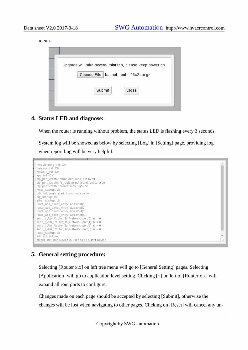
3. Upgrade firmware:
Firmware will be upgrade by selecting [Upgrade Firmware] on [Setting] page, giving a
firmware file, clicking [submit]. Upgrade will take about one or two minutes, webpages
would be auto reloaded. New version number will be shown after “Router” on the left tree
Copyright by SWG automation
Data sheet V2.0 2017-3-18 SWG Automation http://www.hvacrcontrol.com
menu.
4. Status LED and diagnose:
When the router is running without problem, the status LED is flashing every 3 seconds.
System log will be showed as below by selecting [Log] in [Setting] page, providing log
when report bug will be very helpful.
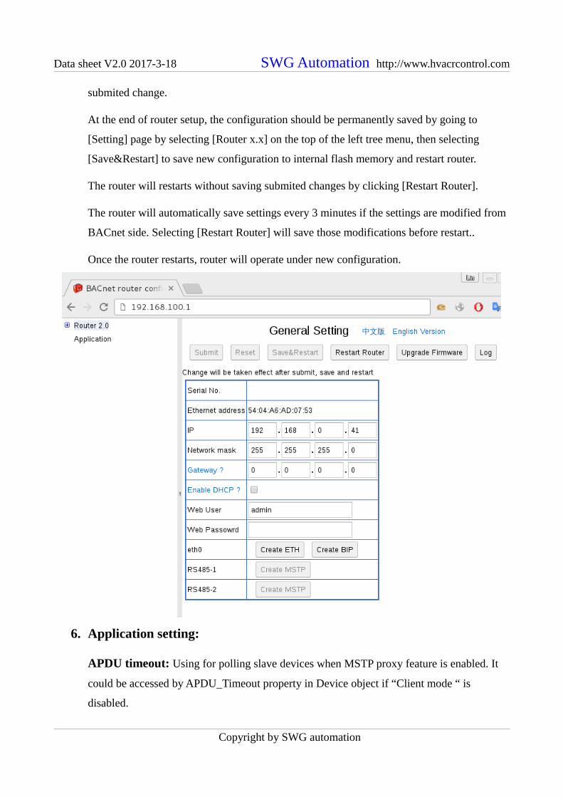
5. General setting procedure:
Selecting [Router x.x] on left tree menu will go to [General Setting] pages. Selecting
[Application] will go to application level setting. Clicking [+] on left of [Router x.x] will
expand all rout ports to configure.
Changes made on each page should be accepted by selecting [Submit], otherwise the
changes will be lost when navigating to other pages. Clicking on [Reset] will cancel any un-
Copyright by SWG automation
Data sheet V2.0 2017-3-18 SWG Automation http://www.hvacrcontrol.com
submited change.
At the end of router setup, the configuration should be permanently saved by going to
[Setting] page by selecting [Router x.x] on the top of the left tree menu, then selecting
[Save&Restart] to save new configuration to internal flash memory and restart router.
The router will restarts without saving submited changes by clicking [Restart Router].
The router will automatically save settings every 3 minutes if the settings are modified from
BACnet side. Selecting [Restart Router] will save those modifications before restart..
Once the router restarts, router will operate under new configuration.
6. Application setting:
APDU timeout: Using for polling slave devices when MSTP proxy feature is enabled. It
could be accessed by APDU_Timeout property in Device object if “Client mode “ is
disabled.
Copyright by SWG automation

Data sheet V2.0 2017-3-18 SWG Automation http://www.hvacrcontrol.com
Number of APDU retries: Using for polling slave devices when MSTP proxy feature is
enabled. It could be accessed by Number_Of_APDU_Retries property in Device object if
“Client mode “ is disabled.
Client mode: If enable there is no Device object inside the router, so below fields is
disabled.
Device Instance/Device Name/Localtion: These fields define corresponding property
values in Device object.
7. Port network number:
Valid network numbers are from 1 to 65534, and should be unique within the BACnet inter-
network. When a port is disabled, it is displayed as crossed out. When it's enabled and
submitted, the network number would be checked for duplication.
Revision 12 of BACnet standard requires router to support What_Is_Network_Number and
Network_Number_Is, so the router will automaticly query and apply network number when
“Not configured” is selected.
8. General runtime info:
If the router's configuration is not changed after its startup, runtime information for every
enabled port could be accessed by selecting [Runtime Info] on each port's setting page.
Copyright by SWG automation
Data sheet V2.0 2017-3-18 SWG Automation http://www.hvacrcontrol.com
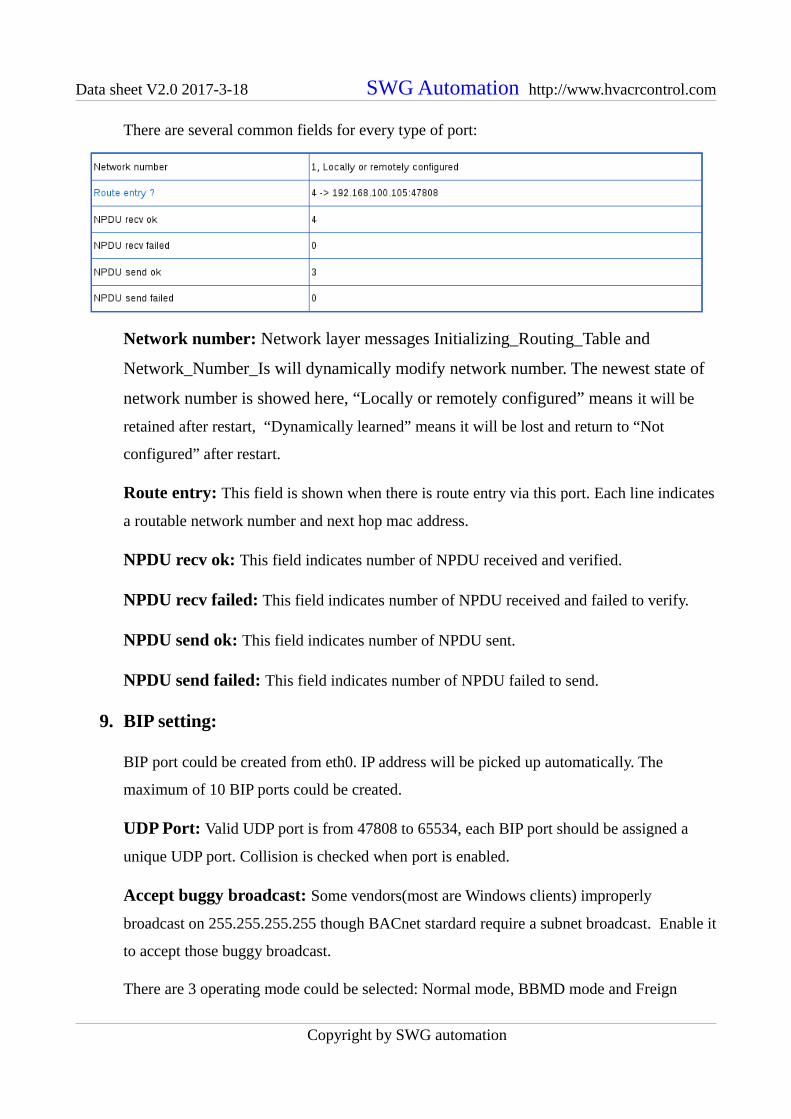
There are several common fields for every type of port:
Network number: Network layer messages Initializing_Routing_Table and
Network_Number_Is will dynamically modify network number. The newest state of
network number is showed here, “Locally or remotely configured” means it will be
retained after restart, “Dynamically learned” means it will be lost and return to “Not
configured” after restart.
Route entry: This field is shown when there is route entry via this port. Each line indicates
a routable network number and next hop mac address.
NPDU recv ok: This field indicates number of NPDU received and verified.
NPDU recv failed: This field indicates number of NPDU received and failed to verify.
NPDU send ok: This field indicates number of NPDU sent.
NPDU send failed: This field indicates number of NPDU failed to send.
9. BIP setting:
BIP port could be created from eth0. IP address will be picked up automatically. The
maximum of 10 BIP ports could be created.
UDP Port: Valid UDP port is from 47808 to 65534, each BIP port should be assigned a
unique UDP port. Collision is checked when port is enabled.
Accept buggy broadcast: Some vendors(most are Windows clients) improperly
broadcast on 255.255.255.255 though BACnet stardard require a subnet broadcast. Enable it
to accept those buggy broadcast.
There are 3 operating mode could be selected: Normal mode, BBMD mode and Freign
Copyright by SWG automation
Data sheet V2.0 2017-3-18 SWG Automation http://www.hvacrcontrol.com
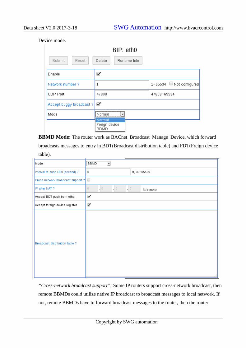
Device mode.
BBMD Mode: The router work as BACnet_Broadcast_Manage_Device, which forward
broadcasts messages to entry in BDT(Broadcast distribution table) and FDT(Freign device
table).
“Cross-network broadcast support”: Some IP routers support cross-network broadcast, then
remote BBMDs could utilize native IP broadcast to broadcast messages to local network. If
not, remote BBMDs have to forward broadcast messages to the router, then the router
Copyright by SWG automation

Data sheet V2.0 2017-3-18 SWG Automation http://www.hvacrcontrol.com
broadcasts messages on local network. Most IP routers do not support this feature. This
parameter is disabled by default.
“IP after NAT”: NAT support is enabled by this parameter.BIP device out of local network
should use this IP to access the router.
“Broadcast distribution table”: The router will automatically add itself into BDT, so only
other BBMDs should be inputed here. Each line should define one BBMD, format as
192.168.20.50:47808. If IP router to remote network supports cross-network broadcast, then
it should be defined as: 192.168.20.50/24:47808, where 24 is netmask bit, means
255.255.255.0
“Interval to push”: BDT in every BBMD should be indenticial. But keeping BDT in every
BBMD updated is repetition. If this parameter is set to non zero value, the router will write
whole BDT to each other BBMD defined in BDT at this interval.
“Accept BDT push from other”: If this parameter is enabled, the router accepts writting to
BDT from other, meanwhile the runtime info shows current BDT. BDT push feature will not
work as expected if other BBMDs not accept BDT push.
“Accept foreign device register”: If this parameter is enabled, the router accepts registering
from foreign device, meanwhile the runtime info shows current FDT.
Foreign Device mode: The route register itself as a foreign device into a remote BBMD.
The remote BBMD should enable “Accept foreign device register”.
“Remote BBMD IP” and “Remote BBMD Port” parameters defines remote BBMD.
“Register interval” paramter defines how often the router register itself to remote BBMD. If
the router access remote BBMD through NAT device, this parameter should be less than the
Copyright by SWG automation

Data sheet V2.0 2017-3-18 SWG Automation http://www.hvacrcontrol.com
UDP timeout defined in NAT device.
“Register time to live” parameter tells remote BBMD to delete the router from its FDT after
the time.
Runtime Info: Particular runtime info for BIP port include BDT and FDT if the router is
operating in BBMD mode and accepts BDT push and foreigh device register.
“Broadcast distribution table” show each entry for each line, the format is same as above
BDT definition.
“Foreigh device table” show each entry as: ip : udp_port ttl remaining_time
10.MSTP setting:
MSTP port could be enabled on RS485-1 or RS485-2 ports. Most of the parameters are
intuitive, but some may need an explanation:
AB line polarity: If “Inverse” is selected, the polarity of EIA-485 wires will be inversed.
If “Auto” is selectced, the router will keep sensing polarity from bus biasing on the fly.
Current polarity detected in “Auto” mode will be found in runtime info.
Fixed/Auto/Forced baudrate: When “Fixed” is selected, the router will keep running on
the baudrate selected. Most devices on the world are running on this mode.
If “Auto” is selected, when there is no valid frame for a while (10 continious error frame),
the router will test other baudrates one by one until it find a valid frame header. The
Copyright by SWG automation

Data sheet V2.0 2017-3-18 SWG Automation http://www.hvacrcontrol.com
baudrate value selected here is firstly tested on startup. If there is no activity on bus when
the router starts, the router will keep silence until baudrate is detected, so there should be at
least one device with “Fixed” or “Forced” mode on the bus.
“Forced” mode works similarly to “Auto” mode, but it will switch the baudrate back to
value selected here when the router get token. This function is designed to help bus runs on
desired baudrate even there is device with wrong baudrate on bus.
Current baudrate detected in “Auto” or “Forced” mode will be found in runtime info.
More detailed info could be found here: http://www.hvacrcontrol.com/fixedautoforced-
baudrate-for-mstp/
Local MAC: The valid range is 0~127
Max master: The valid range is 1~127 and >= Local MAC.
Auto addressing: If “Auto detect” is selected, when the router starts, it will auto detect
max_master, then select largest unused MAC address as local MAC. If there is no activity
on the bus when it starts, the “Local MAC” and “Max master” value inputed here will be
used.
The result of “Local MAC” and “Max master” value will be found in runtime info.
More detailed info could be found here: http://www.hvacrcontrol.com/bacnet-mstp-auto-
addressing/
Max info frames: It define how many NPDUs the router would send when it hold token.
The larger value means better throughout but worse latence (Less token pass rate). The
moderated value for router is 10.
Copyright by SWG automation

Data sheet V2.0 2017-3-18 SWG Automation http://www.hvacrcontrol.com
By occupy time: The NPDUs passing router usually have size between 10~50 bytes, but
could be up to 501 or 1497 (Extended frame). Larger NPDU need more time to send or
receive. For NPDUs which need a reply from targeted device, router has to wait for reply.
Usually the targeted device need more time to handle or generate larger NPDU, router has to
wait longer.
So the time the router holding token could be varied much, which impacts latency guaranty
of MSTP bus. To avoid this problem, “Max_info_frames by token occupy time” feature
limits the router’s token holding time.
The limitation is calculated by: byte_time * 32 * Max_info_frames
More detailed info could be found here: http://www.hvacrcontrol.com/max_info_frames-by-
token-occupy-time/
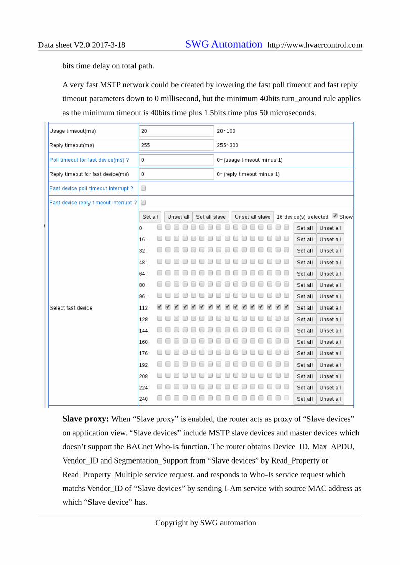
Fast device: To be compatible with some slow responding BACnet devices,, the BACnet
standard allows a relaxed usage_timeout(for Poll_For_Master and Token frame) and
reply_timeout (for DER frame like BACnet_(Extended_)Data_Expecting_Reply frame and
Test_Request frame) to higher values; this will seriously impact the MSTP network
bandwidth. There are two groups of timeouts available for each MS/TP port: A standard
group for usage timeout and reply timeout parameters, and a fast group for poll timeout and
reply timeout parameters. A table with MAC address allows for optimal network tuning by
independently selecting fast devices to use fast group timeout.
The timeout of Token frame for fast device is determined by such rule: if fast poll timeout is
less than 20ms, use 20ms; else use fast poll timeout.
When fast device is offline, the router will exit waiting state fastly, but other devices on the
bus may still wait for unnecessary long time. By enabling “Fast device poll timeout
interrupt” and “Fast device reply timeout interrupt”, when the router has monitored a
Poll_For_Master or DER frame sent to fast device, and the fast device does not repond
within fast Poll timeout or fast Reply timeout, the router sends out data as 0x55, 0xff, 10bits
0, which interrupt the waiting state of sender of the frame.
When fast device is connected by repeater, the delay introduced by repeater should be
counted into timeout. BACnet standard allow 2 bits time delay on each repeater and totol 10
Copyright by SWG automation
Data sheet V2.0 2017-3-18 SWG Automation http://www.hvacrcontrol.com
bits time delay on total path.
A very fast MSTP network could be created by lowering the fast poll timeout and fast reply
timeout parameters down to 0 millisecond, but the minimum 40bits turn_around rule applies
as the minimum timeout is 40bits time plus 1.5bits time plus 50 microseconds.
Slave proxy: When “Slave proxy” is enabled, the router acts as proxy of “Slave devices”
on application view. “Slave devices” include MSTP slave devices and master devices which
doesn’t support the BACnet Who-Is function. The router obtains Device_ID, Max_APDU,
Vendor_ID and Segmentation_Support from “Slave devices” by Read_Property or
Read_Property_Multiple service request, and responds to Who-Is service request which
matchs Vendor_ID of “Slave devices” by sending I-Am service with source MAC address as
which “Slave device” has.
Copyright by SWG automation

Data sheet V2.0 2017-3-18 SWG Automation http://www.hvacrcontrol.com
“Scan interval” parameter defines how often the router scan “Slave devices”. To avoid
starve MSTP bus, the router will only send or re-send one request per second (If remote
device to scan is fast device, more than one request will be sent each second). There is two
ways to scan “Slave devices”, one is auto discovery, another is manual binding:
When auto discovery way is enabled by “Auto discovery” parameter, the BACnet standard
requires the router to scan each MAC address to discover “Slave device”. In practice, there
are few slave devices on a network, so most of scan would get reply timeout(usually timeout
after 255milliseconds), so it wastes lots bandwidth. The “Devices to discovery” function
selectively limits which devices are to be scanned.
For “Slave devices” that that do not support Read_Property service request to the special
device instance of 4194303, only manual binding way works. The bindings of MAC address
Copyright by SWG automation

Data sheet V2.0 2017-3-18 SWG Automation http://www.hvacrcontrol.com
and device instance should be defined in “Manual binding” parameter, seperated by comma
or new line.
Tx/Rx LEDs: Each MSTP port has one Tx(Blue) and one Rx(Red) led, Tx led flashs when
anything is sending out, Rx led flashs only when NPDU for local or broadcasted is received.
Usually when Tx led keeps flashing, it means the router has joined token passing.
Runtime Info: There are many particular runtime info for MSTP port:
“NPDU in send queue”: Because MSTP is much slower than Ethernet and IP, some NPDUs
have to be queued, and send out ordered by priority.
“Send collision count”: After sending, invalid frame received without turn_around is
regarded as collision. It usually indicates device responds too slowly. Adjusting timeout
setting may be helpful to eliminate it.
“Token lost count”: 500ms idle on bus is regarded as token loss. When router startups on a
Copyright by SWG automation
Data sheet V2.0 2017-3-18 SWG Automation http://www.hvacrcontrol.com
idle bus, the count will increase to 1. If a device holding token is powered off or
disconnected from bus, the token will be lost.
“Non fast device reply timeout count”: Non fast device not reply to DER frame sent by the
router.
“Fast device reply timeout count”: Fast device not reply to DER frame sent by the router.
“Fast device reply timeout interrupt count”: Fast device not reply to DER frame sent by
other device, the router interrupts it.
“Retry count to pass token”: When the router fail to pass token to next station, it will retry
once as required by standard.
“Pass token failure count”: The router fail to pass token after retrying.
“Error frame count”: Count for error of: byte receiving, head crc, data crc, inconsistent data
field. The router's fast device reply/poll timeout interrupting will be regarded as a error
frame from other devices view.
“Duplicate token count”: Valid but not expected frame received is regarded as duplication
of token. It usually caused by device which lacks ability of collision detection and responds
too slowly to token passing.
“No turn_around frame count”: Valid frame received without turn_around to previous
frame is regarded as no turn_around frame. It indicates inproper implementation.
“Padding frame count”: Frame padding with 0xff is allowed but not encouraged.
“Token pass rate(round/min)”: This field is counted every 10 seconds. Each time the router
getting a token means a round of token passing.
“Recently active devices”: This field shows source MAC of valid frame appeared on bus in
past 10 seconds. If there has local MAC, it means collision with the router.
“Detected baudrate”/“Detected A/B line reverse”/“Detected local MAC”/“Detected max
master”: These fields are available when auto detection is enabled and detection procedure
is completed.
“Slave proxing”: It is shown when slave proxy is enabled. Each line is a “Slave device”,
formated as
“MAC:Device_ID,Max_APDU,Segmentation_Support,Vendor_ID:Vendor_Name”.
11.Ethernet settting:
Ethernet port could be created from eth0. MAC address will be picked up from eth0
automatically.
Copyright by SWG automation