SVEA - Optoga · SVEA SVEA AC 21/2W LED-module with corridor function ... Wire Connector: CviLux...
22
SVEA SVEA AC 21/2W LED-module with corridor function A qualified solution to replace and exceed CFL and CDM solutions in ambient luminaires. No driver is required!
Transcript of SVEA - Optoga · SVEA SVEA AC 21/2W LED-module with corridor function ... Wire Connector: CviLux...

SVEA
SVEA AC 21/2W
LED-module with corridor function
A qualified solution to replace and exceed CFL
and CDM solutions in ambient luminaires.
No driver is required!

SVEA AC Corridor Document no:
n/a Revision:
0.8 Page:
Page 2 of 22 Object:
Datasheet SVEA AC.23.230.7212.8yy-NN Author:
SL Date:
2015-02-10
Köpingsvägen 4 Ph: +46 (0)589-490 950 Web: www.optoga.se SE-732 31 ARBOGA Fax: +46 (0)589-490 950 E-mail: [email protected]
Designed for retail stores, offices, hospitals and other places where the need is to
create a good atmosphere for people to dwell in whether they take care of
business or socialize.
SVEA AC Corridor Document no:
n/a Revision:
0.8 Page:
Page 3 of 22 Object:
Datasheet SVEA AC.23.230.7212.8yy-NN Author:
SL Date:
2015-02-10
Köpingsvägen 4 Ph: +46 (0)589-490 950 Web: www.optoga.se SE-732 31 ARBOGA Fax: +46 (0)589-490 950 E-mail: [email protected]
Pages for reference:
Pages for reference: ................................................................................................................................ 3
Introduction ............................................................................................................................................. 4
Short form Characteristics ....................................................................................................................... 6
Wiring diagram: ....................................................................................................................................... 8
Article number structure ....................................................................................................................... 10
Dimensions LED Module: ...................................................................................................................... 11
Parameters of the Lens system ............................................................................................................. 12
Parameters of the light output .............................................................................................................. 13
Binning structure graphical representation .......................................................................................... 14
Binning and Labelling ............................................................................................................................ 15
Electro Optical data ............................................................................................................................... 16
Measurement Control ........................................................................................................................... 17
Lifetime (Calculated) ............................................................................................................................. 18
Verification of Conformity ..................................................................................................................... 19
Precautions for use ................................................................................................................................ 20
ROHS Compliant .................................................................................................................................... 21

SVEA AC Corridor Document no:
n/a Revision:
0.8 Page:
Page 4 of 22 Object:
Datasheet SVEA AC.23.230.7212.8yy-NN Author:
SL Date:
2015-02-10
Köpingsvägen 4 Ph: +46 (0)589-490 950 Web: www.optoga.se SE-732 31 ARBOGA Fax: +46 (0)589-490 950 E-mail: [email protected]
Introduction
The LED module and light engine is named Svea and it is a design for light fittings and
luminaires aiming for various areas. It has been designed in order to meet the demands on
high performance optical solutions in both light emitting and in colour rendering.
Mechanically it is constructed with our package design Svea ( ~90 mm) that has the same
footprint as the others in the family both for external drivers as well as built-in drivers for
110/230VAC.
Svea package
The same package is used for Downlight, Spotlight, Tasklight and Medical light fittings etc.
The solution is developed to make it easy for the designers and engineers to choose from low
to high power, from AC to DC and choose between a variety of lenses in the same luminaire
or in similar design. In the design concept there are standard dimmers with the same snap-in
connector (that fits the whole Optodrive™ concept) as well as several heat sink designs with
worldwide distribution.
AC design
All driver and dimmer components are built-in and operate at 110, 230 or 240 VAC
depending on the version with efficiency above 90%. It has a standard plug-in connector that
fits all the different AC designs.
Integrated driver
The advantage with an AC driver that has been built-in is:
Lifetime – Connected to a heat sink and therefore has a controlled environment
Dimming – Dimming via standard trailing edge dimmers
Small – No extra boxes
Simple – Easily adapted into to the production line
Light output
Colour stability is important to ensure that the installation has a uniform light output.
Parameters such as binning, lifetime and thermal control are vital for good results.

SVEA AC Corridor Document no:
n/a Revision:
0.8 Page:
Page 5 of 22 Object:
Datasheet SVEA AC.23.230.7212.8yy-NN Author:
SL Date:
2015-02-10
Köpingsvägen 4 Ph: +46 (0)589-490 950 Web: www.optoga.se SE-732 31 ARBOGA Fax: +46 (0)589-490 950 E-mail: [email protected]
Technical attributes
Energy saving and a very high lumen output
High Colour Rendering
Uniform Colour temperature
Controlled lifetime
Simple integration
High Power Factor
Low Total Harmonic Distortion

SVEA AC Corridor Document no:
n/a Revision:
0.8 Page:
Page 6 of 22 Object:
Datasheet SVEA AC.23.230.7212.8yy-NN Author:
SL Date:
2015-02-10
Köpingsvägen 4 Ph: +46 (0)589-490 950 Web: www.optoga.se SE-732 31 ARBOGA Fax: +46 (0)589-490 950 E-mail: [email protected]
Short form Characteristics
Mechanical
Board dimensions: Hexagonal 83 / 95.7 mm diameter
Wire Connector: CviLux CP04-03S0 or JST BH
Assembly holes: 3 x 3.42 mm
Lens diameter
Lens height:
Electrical
Number of LED’s:
Power supply:
LED current:
Input Voltage: 230VAC
Power: 23W +/-10% ea.
Input Current: 100 mA +/-10% ea.
In Standby mode: ~2W (~1mA)
Module current: 100 mA +/-10% ea.
Power factor: PFC 0.98
Total Harmonic Distortion: < 15% THD
Over temp protection: 150°C
Efficiency
Light
CCT: 2700K, 3000K, 4000K
CRI: > 80 Ra
Light output: 2200 lm
SDCM (Mac Adam) 4
Environmental operation conditions:
Temperature range:
Relative Humidity:
Ambient air pressure:
SVEA AC Corridor Document no:
n/a Revision:
0.8 Page:
Page 7 of 22 Object:
Datasheet SVEA AC.23.230.7212.8yy-NN Author:
SL Date:
2015-02-10
Köpingsvägen 4 Ph: +46 (0)589-490 950 Web: www.optoga.se SE-732 31 ARBOGA Fax: +46 (0)589-490 950 E-mail: [email protected]
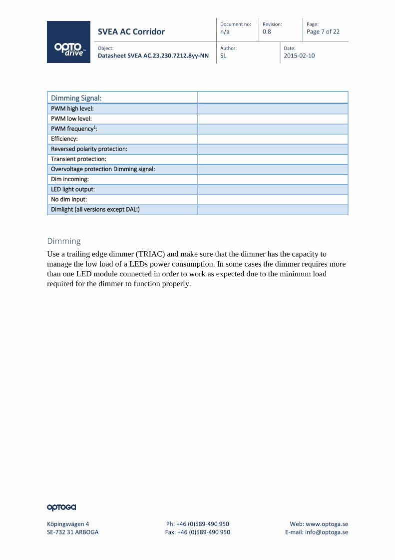
Dimming Signal:
PWM high level:
PWM low level:
PWM frequency1:
Efficiency:
Reversed polarity protection:
Transient protection:
Overvoltage protection Dimming signal:
Dim incoming:
LED light output:
No dim input:
Dimlight (all versions except DALI)
Dimming
Use a trailing edge dimmer (TRIAC) and make sure that the dimmer has the capacity to
manage the low load of a LEDs power consumption. In some cases the dimmer requires more
than one LED module connected in order to work as expected due to the minimum load
required for the dimmer to function properly.
SVEA AC Corridor Document no:
n/a Revision:
0.8 Page:
Page 8 of 22 Object:
Datasheet SVEA AC.23.230.7212.8yy-NN Author:
SL Date:
2015-02-10
Köpingsvägen 4 Ph: +46 (0)589-490 950 Web: www.optoga.se SE-732 31 ARBOGA Fax: +46 (0)589-490 950 E-mail: [email protected]
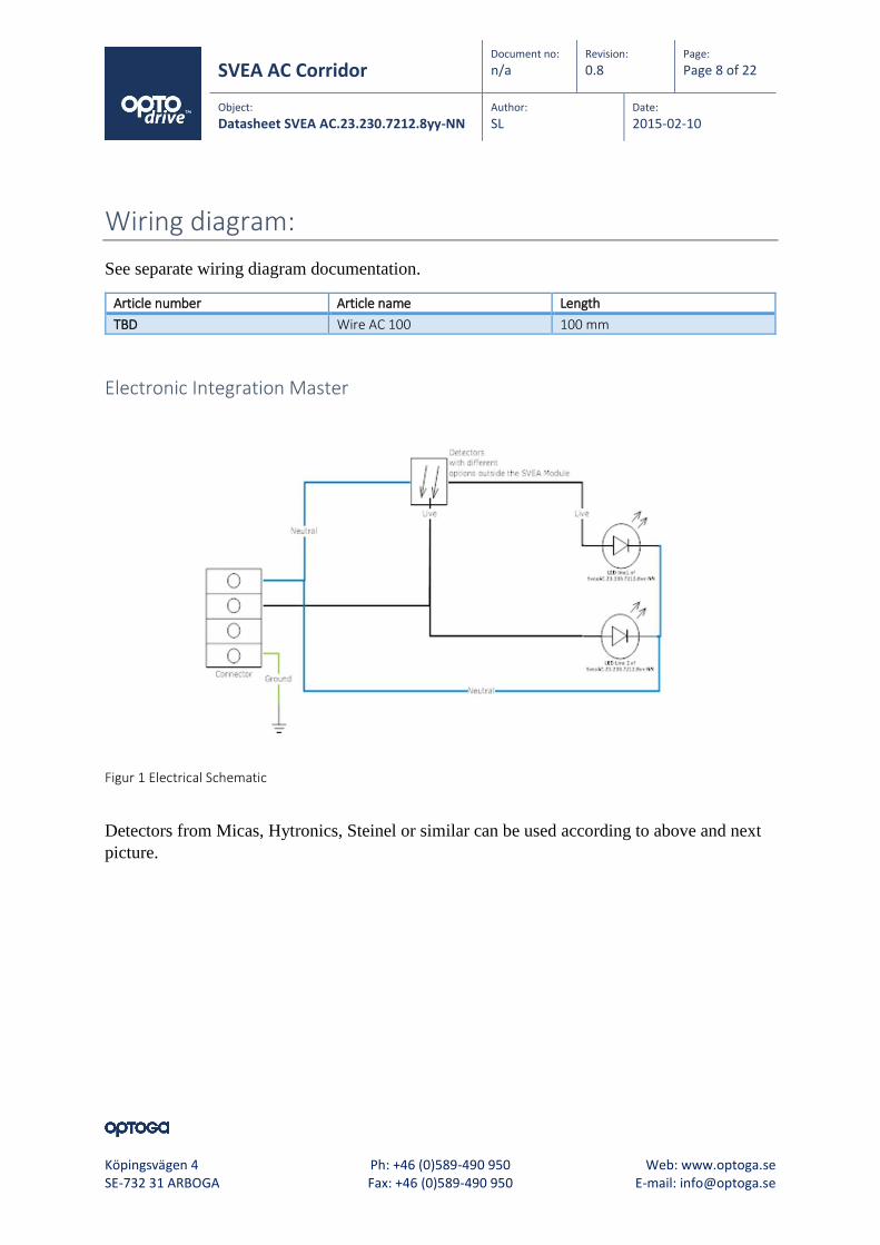
Wiring diagram:
See separate wiring diagram documentation.
Article number Article name Length
TBD Wire AC 100 100 mm
Electronic Integration Master
Figur 1 Electrical Schematic
Detectors from Micas, Hytronics, Steinel or similar can be used according to above and next
picture.

SVEA AC Corridor Document no:
n/a Revision:
0.8 Page:
Page 9 of 22 Object:
Datasheet SVEA AC.23.230.7212.8yy-NN Author:
SL Date:
2015-02-10
Köpingsvägen 4 Ph: +46 (0)589-490 950 Web: www.optoga.se SE-732 31 ARBOGA Fax: +46 (0)589-490 950 E-mail: [email protected]
Electric Integration Light Fitting
Figur 2 Electrical Diagram
The wiring has to be able to work with the different possibilities of detector’s as can be built
in or from a centralized solution. The incoming from the detector is the on/off version and
first low watt version is running 24/7 to create light to be detected for security or as a corridor
function.
SVEA AC Corridor Document no:
n/a Revision:
0.8 Page:
Page 10 of 22 Object:
Datasheet SVEA AC.23.230.7212.8yy-NN Author:
SL Date:
2015-02-10
Köpingsvägen 4 Ph: +46 (0)589-490 950 Web: www.optoga.se SE-732 31 ARBOGA Fax: +46 (0)589-490 950 E-mail: [email protected]
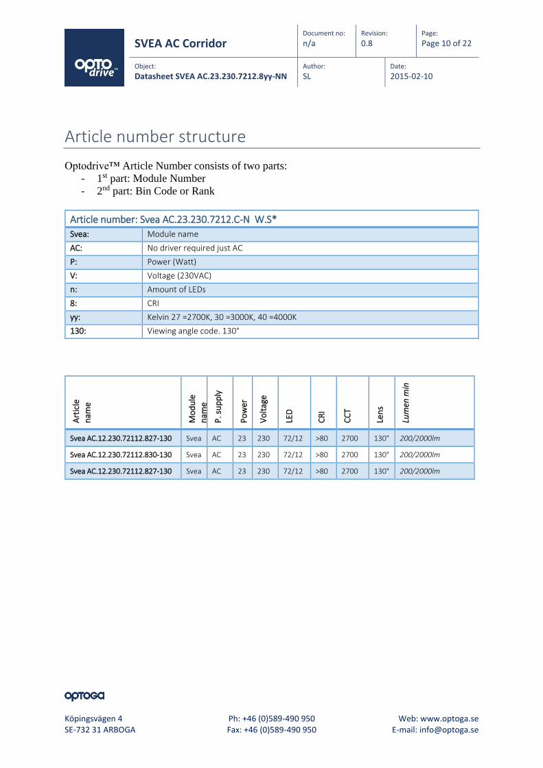
Article number structure
Optodrive™ Article Number consists of two parts:
- 1st part: Module Number
- 2nd part: Bin Code or Rank
Article number: Svea AC.23.230.7212.C-N W.S*
Svea: Module name
AC: No driver required just AC
P: Power (Watt)
V: Voltage (230VAC)
n: Amount of LEDs
8: CRI
yy: Kelvin 27 =2700K, 30 =3000K, 40 =4000K
130: Viewing angle code. 130°
Art
icle
nam
e
Mo
du
le
nam
e
P. s
up
ply
Po
wer
Vo
ltag
e
LED
CR
I
CC
T
Len
s
Lum
en m
in
Svea AC.12.230.72112.827-130 Svea AC 23 230 72/12 >80 2700 130° 200/2000lm
Svea AC.12.230.72112.830-130 Svea AC 23 230 72/12 >80 2700 130° 200/2000lm
Svea AC.12.230.72112.827-130 Svea AC 23 230 72/12 >80 2700 130° 200/2000lm

SVEA AC Corridor Document no:
n/a Revision:
0.8 Page:
Page 11 of 22 Object:
Datasheet SVEA AC.23.230.7212.8yy-NN Author:
SL Date:
2015-02-10
Köpingsvägen 4 Ph: +46 (0)589-490 950 Web: www.optoga.se SE-732 31 ARBOGA Fax: +46 (0)589-490 950 E-mail: [email protected]
Dimensions LED Module:
SVEA AC Corridor Document no:
n/a Revision:
0.8 Page:
Page 12 of 22 Object:
Datasheet SVEA AC.23.230.7212.8yy-NN Author:
SL Date:
2015-02-10
Köpingsvägen 4 Ph: +46 (0)589-490 950 Web: www.optoga.se SE-732 31 ARBOGA Fax: +46 (0)589-490 950 E-mail: [email protected]
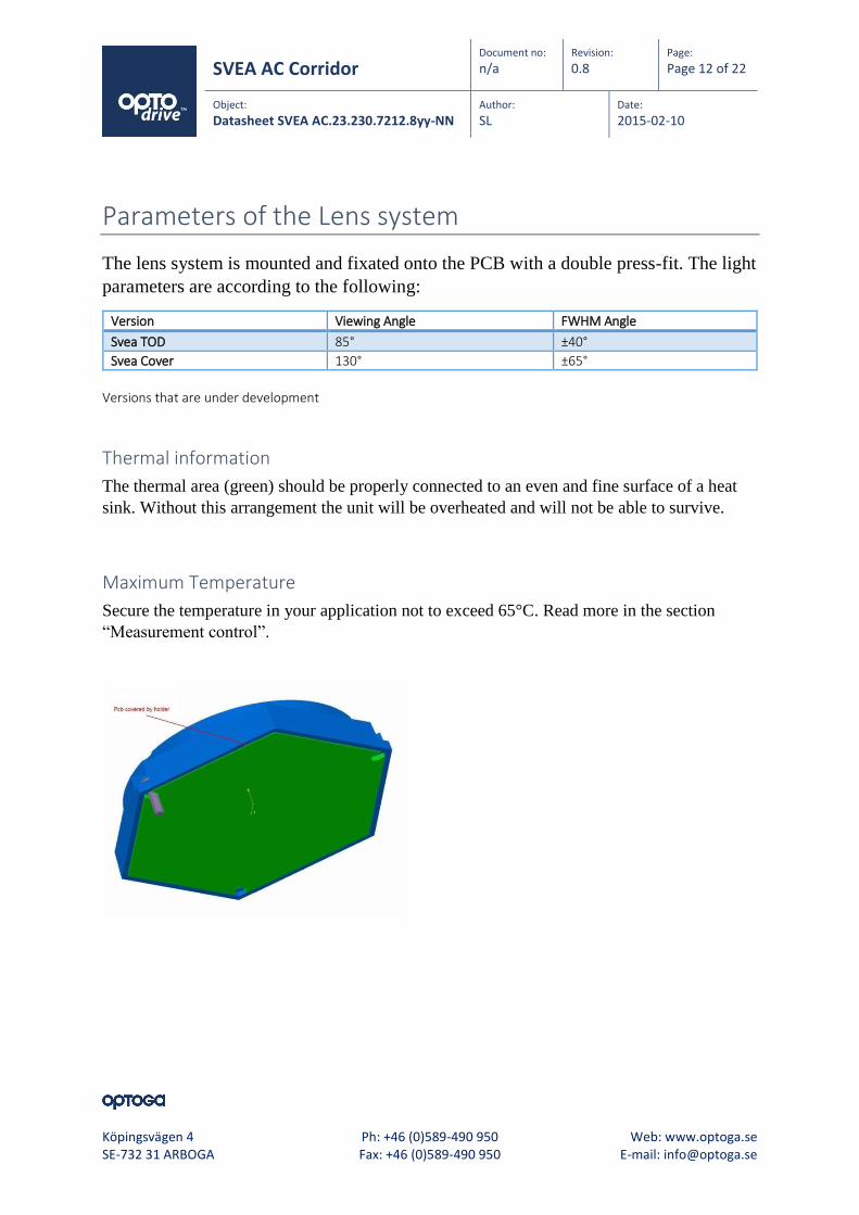
Parameters of the Lens system
The lens system is mounted and fixated onto the PCB with a double press-fit. The light
parameters are according to the following:
Version Viewing Angle FWHM Angle
Svea TOD 85° ±40°
Svea Cover 130° ±65°
Versions that are under development
Thermal information
The thermal area (green) should be properly connected to an even and fine surface of a heat
sink. Without this arrangement the unit will be overheated and will not be able to survive.
Maximum Temperature
Secure the temperature in your application not to exceed 65°C. Read more in the section
“Measurement control”.

SVEA AC Corridor Document no:
n/a Revision:
0.8 Page:
Page 13 of 22 Object:
Datasheet SVEA AC.23.230.7212.8yy-NN Author:
SL Date:
2015-02-10
Köpingsvägen 4 Ph: +46 (0)589-490 950 Web: www.optoga.se SE-732 31 ARBOGA Fax: +46 (0)589-490 950 E-mail: [email protected]
Parameters of the light output
SVEA AC 200/2000lm
Electro-Optical characteristics LED module at IF=55mA, 230VAC, TA=25ºC
Parameter Symbol Value Unit
Min Typ Max
Luminous Flux 21W Channel 1 2000 lm
2W Channel 2 150 lm
Correlated Colour Temperature
27*(2) CCT 2700 K
30*(2) CCT 3000 K
40*(2 CCT 4000 K
CRI Ra 80 84 - -
Power Po 20.5 23 25.5 W
(2)See detailed information in chapter” Binning structure graphical representation”
Colour Spectrum Warm White

SVEA AC Corridor Document no:
n/a Revision:
0.8 Page:
Page 14 of 22 Object:
Datasheet SVEA AC.23.230.7212.8yy-NN Author:
SL Date:
2015-02-10
Köpingsvägen 4 Ph: +46 (0)589-490 950 Web: www.optoga.se SE-732 31 ARBOGA Fax: +46 (0)589-490 950 E-mail: [email protected]
Binning structure graphical representation
Binning structure graphical representation IEC 1976
Note the availability and representation on the IEC 1976 graph shown below.
* Note that the Blue boxes represent Energy Star Rank
Short form in diagram Colour Code CCT
H 27 2700K
G 30 3000K
E 40 4000K

SVEA AC Corridor Document no:
n/a Revision:
0.8 Page:
Page 15 of 22 Object:
Datasheet SVEA AC.23.230.7212.8yy-NN Author:
SL Date:
2015-02-10
Köpingsvägen 4 Ph: +46 (0)589-490 950 Web: www.optoga.se SE-732 31 ARBOGA Fax: +46 (0)589-490 950 E-mail: [email protected]
Binning and Labelling
Colour Rendering Index (CRI)
CRI code CRI (min) Ra
8 80
Short form letters for CCT (K)
Colour Code CCT
27 2700K
30 3000K
40 4000K
Luminous Flux Bins pro LED (lm)
Intensity Code Lumen output (lm) Internal use
3 >1100
4 >1100
5 >1100
6 >1100
7 >1100
8 >1100

SVEA AC Corridor Document no:
n/a Revision:
0.8 Page:
Page 16 of 22 Object:
Datasheet SVEA AC.23.230.7212.8yy-NN Author:
SL Date:
2015-02-10
Köpingsvägen 4 Ph: +46 (0)589-490 950 Web: www.optoga.se SE-732 31 ARBOGA Fax: +46 (0)589-490 950 E-mail: [email protected]
Electro Optical data
Current vs. Voltage
With increasing voltage the light output and the heat increases.
Temperature Characteristics
Consider the thermal capabilities of where the LED module is to be fitted. The temperature is
an important factor for light output as well as for long time light output degradation.
0%
20%
40%
60%
80%
100%
120%
25° 35° 45° 55° 65°
Performance vs. Temperature (°C)
Decrease in performance
SVEA AC Corridor Document no:
n/a Revision:
0.8 Page:
Page 17 of 22 Object:
Datasheet SVEA AC.23.230.7212.8yy-NN Author:
SL Date:
2015-02-10
Köpingsvägen 4 Ph: +46 (0)589-490 950 Web: www.optoga.se SE-732 31 ARBOGA Fax: +46 (0)589-490 950 E-mail: [email protected]
Measurement Control
The recommended maximum value is 65°C on Tc or measuring point. If this value is
exceeded we cannot guarantee the function and the lifetime of the product. The purpose of the
measurement is to control the Junction (Tj) temperature of the LED and also in order to
control the performance on the complete setup. By measuring the junction temperature (Tj)
the average lifetime of the product is known.
The thermal connection is measured in temperature vs. Power.
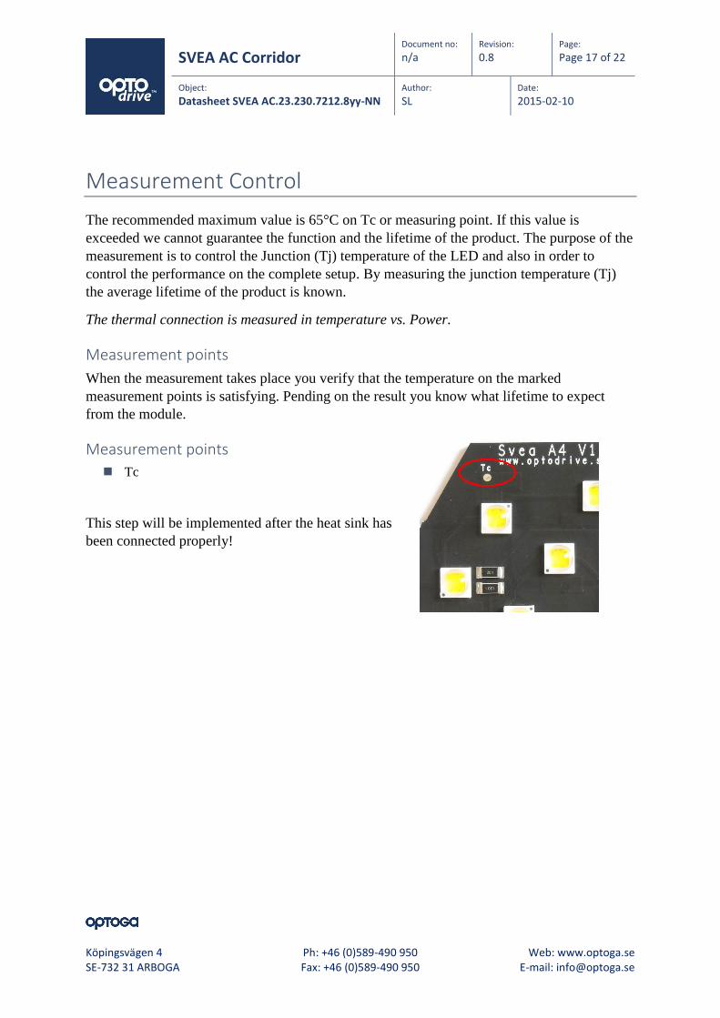
Measurement points
When the measurement takes place you verify that the temperature on the marked
measurement points is satisfying. Pending on the result you know what lifetime to expect
from the module.
Measurement points
Tc
This step will be implemented after the heat sink has
been connected properly!

SVEA AC Corridor Document no:
n/a Revision:
0.8 Page:
Page 18 of 22 Object:
Datasheet SVEA AC.23.230.7212.8yy-NN Author:
SL Date:
2015-02-10
Köpingsvägen 4 Ph: +46 (0)589-490 950 Web: www.optoga.se SE-732 31 ARBOGA Fax: +46 (0)589-490 950 E-mail: [email protected]
Lifetime (Calculated)
The lifetime is calculated at the maximum temperature recommended at the Tc (measuring
point). It is important not to exceed this recommendation; you find more information under
the chapter “measurement control”.
Tc(Surface temperature) Time for 70% light-output 25°C 55000Hr 65°C 40000Hr
SVEA AC Corridor Document no:
n/a Revision:
0.8 Page:
Page 19 of 22 Object:
Datasheet SVEA AC.23.230.7212.8yy-NN Author:
SL Date:
2015-02-10
Köpingsvägen 4 Ph: +46 (0)589-490 950 Web: www.optoga.se SE-732 31 ARBOGA Fax: +46 (0)589-490 950 E-mail: [email protected]
Verification of Conformity
All our modules are controled and verified by Intertek and this is under process for IEC 62031
aprovel.

SVEA AC Corridor Document no:
n/a Revision:
0.8 Page:
Page 20 of 22 Object:
Datasheet SVEA AC.23.230.7212.8yy-NN Author:
SL Date:
2015-02-10
Köpingsvägen 4 Ph: +46 (0)589-490 950 Web: www.optoga.se SE-732 31 ARBOGA Fax: +46 (0)589-490 950 E-mail: [email protected]
Precautions for use
This device should not be used in any type of fluids such as water, oil, organic solvent etc.
When cleaning is required, use only water together with mild soap on the outside of the lens.
Cleaning inside of the LED module is strictly prohibited.
The appearance and specifications of the product may be modified for improvement without
notice.
Long time exposure of sunlight or occasional UV exposure will cause lens discoloration.
Opening of the LED module is prohibited due to risk of EMC, dust, grease and other exposures
that will damage it.
The LED Module should always be mounted to a proper heat sink before it’s connected with its
proper leads.
Handling in regards to static electricity
The Optodrive products have integrated circuits (IC) on board that may be damaged if exposed
to static electricity. Please handle the products only while using equipment that prevents static
electricity. Do not handle them without having ESD protection.
The Optodrive products are not be installed into the end product without proper ESD
protection.
Storage before use
Use only properly rated test equipment and tools for the rated voltage and current of the
product being tested.
It is strongly suggested to wear rubber insulated gloves and rubber bottom shoes while
handling the product.
Do not wear any conductive items (such as jewelry) which could accidentally contact electric
circuits.
Faults, lightning, or switching transients can cause voltage surges in excess of the normal
ratings.
Internal component failure can cause excessive voltages.
Stored or residual electricity in long wire could be hazardous.

SVEA AC Corridor Document no:
n/a Revision:
0.8 Page:
Page 21 of 22 Object:
Datasheet SVEA AC.23.230.7212.8yy-NN Author:
SL Date:
2015-02-10
Köpingsvägen 4 Ph: +46 (0)589-490 950 Web: www.optoga.se SE-732 31 ARBOGA Fax: +46 (0)589-490 950 E-mail: [email protected]
ROHS Compliant
All our LED modules meet the Restrictions of Hazardous Substances (RoHS)!
There has been a growing consensus that Lead Free Systems should increase for the safety of
our environment. It is a very serious problem that lead and other harmful materials are being
used in commercial and industrial products, causing more and more environmental problems.
This has led to regulations such as RoHS (Restriction of the use of certain Hazardous
Substances) from the EU and the Japan Ministry of Trade and Industry (MITI). All LED
module makers providing products to these countries should comply with these restrictions. In
order to meet the RoHS regulation, Optoga is strictly implementing a ban on lead and other
hazardous materials in its products. This is in compliance with our responsibilities as good
corporate citizens.
Design for Environment:
According to the EU-directive 2002/95/EC (RoHS) the following substances must not be used
in this product
Lead (Pb) alloys
Mercury (Hg)
Cadmium (Cd)
Chromium (6+) compounds

Do you want to know
more about the benefits
of OptoDrive™ LED?
Read more about OptoDrive™ at www.optodrive.se. You can also register your
interest via [email protected].
Obviously, you can also call us on +46 (0)589 490 950.
Optoga AB
Founded in November 2004, Optoga has over 30 years of experience in electronic
components. The company develops and supplies LEDs, LED drivers, LED modules
and software solutions for the lighting industry, vehicle manufacturers and
electronics companies.
By developing products with integrated LED and driver electronics, Optoga has
taken the initiative to replace strip lights, incandescent and halogen bulbs with
LED-based light sources.
Köpingsvägen 4 • SE-732 31 Arboga • Tel +46 (0) 589 490 950 • Fax +46 (0) 589 197 80
[email protected] • www.optodrive.se


![2012E CviLux profileII.ppt [相容模式]Microsoft PowerPoint - 2012E CviLux profileII.ppt [相容模式] Author: EN0322 Created Date: 11/2/2012 5:11:20 PM ...](https://static.fdocuments.us/doc/165x107/5fbcb980d7d45d4c9b3b1279/2012e-cvilux-c-microsoft-powerpoint-2012e-cvilux-c-author.jpg)