SURFACE SNOW MELTING AND ANTI-ICING - … · ElectroMelt heating cable surface snow melting and...
34
This step-by-step design guide provides the tools necessary to design a Raychem ElectroMelt heating cable surface snow melting and anti-icing system. For other applications or for design assistance, contact your Thermal Management representative or call (800) 545-6258. Also, visit our web site at www.pentairthermal.com. Contents Introduction 1 How to Use this Guide 2 Safety Guidelines 2 Warranty 2 System Overview 3 Typical System 3 Self-Regulating Heating Cable Construction 4 Approvals 5 Surface Snow Melting and Anti-Icing Applications 5 Surface Snow Melting and Anti-Icing Design 6 Design Step by Step 6 Step 1 Determine design conditions 7 Step 2 Select the heating cable 8 Step 3 Determine the required watt density 9 Step 4 Determine heating cable spacing 11 Step 5 Determine the total area to be protected 13 Step 6 Determine heating cable length 14 Step 7 Determine the electrical parameters 16 Step 8 Select the connection kits and accessories 18 Step 9 Select the control system and power distribution 21 Step 10 Complete the Bill of Materials 27 ElectroMelt System Surface Snow Melting and Anti-Icing Design Worksheet 28 INTRODUCTION Raychem ElectroMelt heating cable systems can be used as a surface snow melting system when installed in concrete pavement or under paving stones. It can also be used as an anti-icing system but only when installed in concrete pavement. Important: ElectroMelt is not approved for use in asphalt. If your application conditions are different, or if you have any questions, contact your Thermal Management representative or call (800) 545-6258. SURFACE SNOW MELTING AND ANTI-ICING – ELECTROMELT SYSTEM 1 / 34 Raychem-DG-H53393-ElectroMeltSnowMeltingCOM-EN-1707 THERMAL MANAGEMENT
Transcript of SURFACE SNOW MELTING AND ANTI-ICING - … · ElectroMelt heating cable surface snow melting and...
This step-by-step design guide provides the tools necessary to design a Raychem ElectroMelt heating cable surface snow melting and anti-icing system For other applications or for design assistance contact your Thermal Management representative or call (800) 545-6258 Also visit our web site at wwwpentairthermalcom
ContentsIntroduction 1
How to Use this Guide 2Safety Guidelines 2Warranty 2
System Overview 3Typical System 3Self-Regulating Heating Cable Construction 4Approvals 5
Surface Snow Melting and Anti-Icing Applications 5Surface Snow Melting and Anti-Icing Design 6
Design Step by Step 6Step 1 Determine design conditions 7Step 2 Select the heating cable 8Step 3 Determine the required watt density 9Step 4 Determine heating cable spacing 11Step 5 Determine the total area to be protected 13Step 6 Determine heating cable length 14Step 7 Determine the electrical parameters 16Step 8 Select the connection kits and accessories 18Step 9 Select the control system and power distribution 21Step 10 Complete the Bill of Materials 27
ElectroMelt System Surface Snow Melting and Anti-Icing Design Worksheet 28
INTRODUCTION
Raychem ElectroMelt heating cable systems can be used as a surface snow melting system when installed in concrete pavement or under paving stones It can also be used as an anti-icing system but only when installed in concrete pavement
Important ElectroMelt is not approved for use in asphalt
If your application conditions are different or if you have any questions contact your Thermal Management representative or call (800) 545-6258
SURFACE SNOW MELTING AND ANTI-ICING ndash ELECTROMELT SYSTEM
1 34Raychem-DG-H53393-ElectroMeltSnowMeltingCOM-EN-1707THERMAL MANAGEMENT
How to Use this GuideThis design guide presents Thermal Managementrsquos recommendations for designing an ElectroMelt surface snow melting and anti-icing system It provides design and performance data electrical sizing information and heating-cable layout suggestions Following these recommendations will result in a reliable energy-efficient system
Follow the design steps in the section ldquoSurface Snow Melting and Anti-Icing Designrdquo page 6 and use the ldquoElectroMelt System Surface Snow Melting and Anti-Icing Design Worksheetrdquo page 28 to document the project parameters that you will need for your projectrsquos Bill of Materials
OTHER REQUIRED DOCUMENTS
This guide is not intended to provide comprehensive installation instructions For complete ElectroMelt surface snow melting system and anti-icing installation instructions please refer to the following additional required documentsbull ElectroMelt System Installation and Operation Manual (H58086)bull Additional installation instructions that are included with the connection kits
thermostats controllers and accessories
If you do not have these documents you can obtain them from the Thermal Management web site at wwwpentairthermalcom
For products and applications not covered by this design guide please contact your Thermal Management representative or call (800) 545-6258
Safety GuidelinesAs with any electrical equipment the safety and reliability of any system depends on the quality of the products selected and the manner in which they are installed and maintained Incorrect design handling installation or maintenance of any of the system components could damage the system and may result in inadequate performance overheating electric shock or fire To minimize these risks and to ensure that the system performs reliably read and carefully follow the information warnings and instructions in this guide
This symbol identifies important instructions or information
This symbol identifies particularly important safety warnings that must be followed
WARNING To minimize the danger of fire from sustained electrical arcing if the heating cable is damaged or improperly installed and to comply with the requirements of Thermal Management agency certifications and national electrical codes ground-fault equipment protection must be used on each heating cable branch circuit Arcing may not be stopped by conventional circuit protection
WarrantyThermal Managementrsquo standard limited warranty applies to Raychem Snow Melting Systems
An extension of the limited warranty period to ten (10) years from the date of installation is available except for the control and distribution systems if a properly completed online warranty form is submitted within thirty (30) days from the date of installation You can access the complete warranty on our web site at wwwpentairthermalcom
SURFACE SNOW MELTING AND ANTI-ICING ndash ELECTROMELT SYSTEM
2 34 THERMAL MANAGEMENTRaychem-DG-H53393-ElectroMeltSnowMeltingCOM-EN-1707
SYSTEM OVERVIEW
The Raychem ElectroMelt system provides surface snow melting and anti-icing for concrete surfaces and pavement The ElectroMelt system uses a self-regulating heating cable that reduces heat output automatically as the pavement warms resulting in lower energy use and eliminating the possibility of overheating The system includes heating cable connection kits junction boxes a control system and sensors power distribution panels and the tools necessary for a complete installation
Typical SystemA typical system includes the followingbull ElectroMelt self-regulating heating cablebull Connection kits and accessoriesbull Snow controller and sensorsbull Power distribution
Aerial Snow Sensor
Heating Cable Splice
Heating Cable Expansion Joint Kit
Power Distribution Panel
Pavement Snow Sensor
Caution Sign
Power Connection and End Seal
Snow Controller
APS-4
SUPPLYSNOW
HEATERGROUND FAULT
GROUND FAULT
HEATER CYCLERESETTEST
HOLD ON TIME (HRS)
SnowIce Melting Controller
SUPPLY 277 VAC 5060HZZ 35VA
HEATER 377 VAC 40 AMP MAX RESIS
USE ONLY COPPER CONDUCTORS HAVING
SUFFICIENT AMPACITY
SEE INSTALLATION INSTRUCTIONS
WARNING
DANGER OF ELECTRICAL SHOCK OR ELCTROCUTION
Lethal voltages are present beneath this cover Servicee by
qualified personnel only More than one disconnect may be
required to de-energize this control for servicing
GROUND FAULT
GROUND FAULT
HOLD ON TIME (HRS)
SNOW
HEATERGROUND FAULT
GROUND FAULT
HEATER CYCLERESETTEST
HOLD ON TIME (HRS)
SUPPLY 277 VAC 5060HZZ 35VA
HEATER 377 VAC 40 AMP MAX RESIS
USE ONLY COPPER CONDUCTORS HAVING
SUFFICIENT AMPACITY
SEE INSTALLATION INSTRUCTIONS
WARNING
DANGER OF ELECTRICAL SHOCK OR ELCTROCUTION
Lethal voltages are present beneath this cover Servicee by
qualified personnel only More than one disconnect may be
required to de-energize this control for servicing
APS-4
SUPPLY
SnowIce Melting Controller
Fig 1 Typical ElectroMelt system
3 34THERMAL MANAGEMENT Raychem-DG-H53393-ElectroMeltSnowMeltingCOM-EN-1707
Self-Regulating Heating Cable Construction
The ElectroMelt self-regulating heating cable is embedded in concrete pavement to melt snow and ice that might otherwise accumulate on the surface The heating cable responds to the local concrete temperature increasing heat output when concrete temperature drops and decreasing heat output when concrete temperature rises The self-regulating heating cable cannot overheat and destroy itself even if overlapped in the concrete and therefore does not require the use of overlimit thermostats
Nickel-plated copper bus wire
Self-regulating conductive core
Modified polyolefin inner jacket
Tinned-copper braid
Modified polyolefin outer jacket
Fig 2 ElectroMelt heating cable construction
With self-regulating technology the number of electrical paths between bus wires changes in response to temperature fluctuations As the temperature surrounding the heater decreases the conductive core contracts microscopically This contraction decreases electrical resistance and creates numerous electrical paths between the bus wires Current flows across these paths to warm the core
As the temperature rises the core expands microscopically This expansion increases electrical resistance and the number of electrical paths decreases The heating cable automatically reduces its output
At low temperature there are many
conducting paths resulting in high output and rapid heat-up Heat
is generated only when it is needed and precisely
where it is needed
At high temperature there are few conduct-ing paths and output is correspondingly lower
conserving energy during operation
At moderate temperature there are fewer conducting paths because the heating cable efficiently adjusts by
decreasing output eliminating any possibility of overheating
The following graphs illustrate the response of self-regulating heating cables to changes in temperature As the temperature rises electrical resistance increases and our heaters reduce their power output
Temperature
Res
ista
nce
Pow
er
Temperature
Constant wattage
Constant wattage
Self-re
gulat
ing
Self-regulating
Fig 3 Self-regulating heating cable technology
SURFACE SNOW MELTING AND ANTI-ICING ndash ELECTROMELT SYSTEM
4 34 THERMAL MANAGEMENTRaychem-DG-H53393-ElectroMeltSnowMeltingCOM-EN-1707
Approvals
The ElectroMelt surface snow melting and anti-icing system is UL Listed and CSA Certified for use in nonhazardous locations
-w
SURFACE SNOW MELTING AND ANTI-ICING APPLICATIONS
SURFACE SNOW MELTING
Surface snow melting systems prevent the accumulation of snow on ramps slabs driveways sidewalks platform scales and stairs under most snow conditions
ANTI-ICING
Anti-icing systems keep the surface temperature above freezing at all times to prevent ice formation Anti-icing applications require a higher watt density and longer hours of operation than a surface snow melting system
APPLICATION REQUIREMENTS AND ASSUMPTIONS
The design for a standard surface snow melting and anti-icing application is based on the following
Reinforced Concretebull 4 to 6 inches (10 to 15 cm) thickbullPlaced on grade bullStandard density
Heating cablebullSecured to reinforcement steel or
meshbullLocated 1 12 to 2 inches (4 to 6 cm)
below finished surfacePaversbullConcrete pavers 1 to 1 12
(25 to 4 cm) inches thickbullPlaced on concrete or mortar base on
grade
Heating cablebullSecured to meshbullEmbedded in concrete or mortar base
below the pavers
For products and applications not covered by this guide contact your Thermal Management representative for design assistance Using proprietary computer modeling Thermal Management can design the appropriate system for these applications
The following are examples of applications not addressed in this design guidebull Concrete thinner than 4 inches (10 cm)bull Concrete thicker than 6 inches (15 cm)bull Lightweight concretebull Concrete with pavers thicker than 1 12 inches (4 cm)bull Ramps and walkways with air belowbull Concrete without reinforcementbull Retrofitting of heating cable to existing pavementbull Pavers composed of material other than concrete
5 34THERMAL MANAGEMENT Raychem-DG-H53393-ElectroMeltSnowMeltingCOM-EN-1707
SURFACE SNOW MELTING AND ANTI-ICING DESIGN
This section details the steps necessary to design your application The examples provided in each step are intended to incrementally illustrate sample designs from start to finish As you go through each step use the ldquoElectroMelt System Surface Snow Melting and Anti-Icing Design Worksheetrdquo page 28 to document your project parameters so that by that end of this section you will have the information you need for your Bill of Materials
SnoCalc is an online design tool available to help you create surface snow melting designs and layouts It is available at httpwwwpentairthermalcom
Design Step by Step
Your system design requires the following essential steps
Determine design conditions
Select the heating cable
Determine the required watt density
Determine heating cable spacing
Determine the total area to be protected
Determine heating cable length
Determine the electrical parameters
Select the connection kits and accessories
Select the control system and power distribution
Complete the Bill of Materials
SURFACE SNOW MELTING AND ANTI-ICING ndash ELECTROMELT SYSTEM
6 34 THERMAL MANAGEMENTRaychem-DG-H53393-ElectroMeltSnowMeltingCOM-EN-1707
Surface Snow Melting and Anti-Icing
1 Determine design conditions
2 Select the heating cable
3 Determine the required watt density
4 Determine heating cable spacing
5 Determine the total area to be protected
9 Select the control system and power distribution
6 Determine heating cable length
7 Determine the electrical parameters
8 Select the connection kits and accessories
10 Complete the Bill of Materials
Step Determine design conditions
Collect the following information to determine your design conditionsbull Application (surface snow melting or anti-icing)bull Environment
ndash For surface snow melting Geographical location ndash For anti-icing Minimum ambient temperature and average wind speed
bull Paving materialbull Size and layout
ndash Slab surface area ndash Ramp surface area ndash Stairs
- Number of stairs - Width of stair - Riser height - Depth of stair - Landing dimensions
ndash Wheel tracks - Track length
ndash Concrete joints ndash Surface drains ndash Location of area structures ndash Other information as appropriate
bull Supply voltagebull Automatic or manual control method
Note Drainage must be a primary concern in any snow melting system design Improper drainage can result in ice formation on the surface of the heated area once the system is de-energized Ice formation along the drainage path away from the heated area may create an ice dam and prohibit proper draining If your design conditions may lead to drainage problems please contact Thermal Management Technical Support for assistance
PREPARE SCALE DRAWING
Draw to scale the snow melting area and note the rating and location of the voltage supply Include stairs and paths for melting water runoff Show concrete joints surface drains and location of area structures including post installations for railings permanent benches and flagpoles Measurements for each distinct section of the snow melting application including stairs will allow for an accurate system design including control configuration Use these symbols to indicate the heating cable expansion and crack-control joints
S
Power connectionEnd seal
Splice
Expansion jointCrack-control joint
Expansion joint kit
E
P
Fig 4 Design symbols
7 34THERMAL MANAGEMENT Raychem-DG-H53393-ElectroMeltSnowMeltingCOM-EN-1707
Example Surface Snow Melting SystemApplication Surface snow meltingGeographical location Buffalo NYSize and layout 80 ft x 50 ft (244 m x 152 m)Paving material Concrete slabStairs
Number of stairs 10Width of stair 5 ft (15 m)Riser height 6 in (15 cm)Depth of stair 12 in (30 cm)
Supply voltage 277 VPhase Single-phaseControl method Automatic snow melting controller
Example Anti-Icing SystemApplication Anti-icingMinimum ambient temperature 10degF (ndash12degC)Average wind speed 20 mph (32 kmph)Size and layout 80 ft x 50 ft (244 m x 152 m)Paving material Concrete slabStairs
Number of stairs 10Width of stair 5 ft (15 m)Riser height 6 in (20 cm)Depth of stair 12 in (30 cm)
Supply voltage 277 VPhase Single-phaseControl method Slab sensing thermostat
Surface Snow Melting and Anti-Icing
1 Determine design conditions
2 Select the heating cable
3 Determine the required watt density
4 Determine heating cable spacing
5 Determine the total area to be protected
9 Select the control system and power distribution
6 Determine heating cable length
7 Determine the electrical parameters
8 Select the connection kits and accessories
10 Complete the Bill of Materials
Step Select the heating cable
Thermal Management offers the option of two self-regulating heating cables with the ElectroMelt system Cable selection is independent of application and depends only upon supply voltage ElectroMelt heating cables must only be powered by single phase voltage In applications where the power supply is three-phase all circuits must be wired to provide single-phase voltage to the heating cables Select the appropriate cable based on the supply voltage available for the application area
TAbLE 1 ELECTROMELT SELF-REGULATING HEATING CAbLESupply voltage Catalog number208 V 240 V 277 V EM2-XR
Example Surface Snow Melting SystemSupply voltage 277 V (from Step 1)Heating cable EM2-XR
Example Anti-Icing SystemSupply voltage 277 V (from Step 1)Heating cable EM2-XR
SURFACE SNOW MELTING AND ANTI-ICING ndash ELECTROMELT SYSTEM
8 34 THERMAL MANAGEMENTRaychem-DG-H53393-ElectroMeltSnowMeltingCOM-EN-1707
Surface Snow Melting and Anti-Icing
1 Determine design conditions
2 Select the heating cable
3 Determine the required watt density
4 Determine heating cable spacing
5 Determine the total area to be protected
9 Select the control system and power distribution
6 Determine heating cable length
7 Determine the electrical parameters
8 Select the connection kits and accessories
10 Complete the Bill of Materials
Step Determine the required watt density
SURFACE SNOW MELTING
For maximum performance from any snow melting system you must first take into account the local snowfall and icing patterns A system design that works well in one city may be inadequate in another The energy required to melt snow varies with air temperature wind speed relative humidity snow density and the depth of the snow on the pavement
Table 2 summarizes the required watt density for most major cities in North America based on typical minimum ambient temperatures and the snowfall and icing patterns Select the city from the list or closest city where similar climatic conditions exist
TAbLE 2 REQUIRED WATT DENSITY FOR SURFACE SNOW MELTINGWattsft2 Wattsm2
City Concrete Pavers Concrete PaversUSABaltimore MD 35 40 377 431 Boston MA 35 40 377 431 Buffalo NY 40 45 431 484 Chicago IL 35 40 377 431 Cincinnati OH 35 40 377 431 Cleveland OH 35 40 377 431 Denver CO 35 40 377 431 Detroit MI 35 40 377 431 Great Falls MT 50 50 538 538 Greensboro NC 35 35 377 377 Indianapolis IN 35 40 377 431 Minneapolis MN 50 50 538 538 New York NY 35 40 377 431 Omaha NE 45 50 484 538 Philadelphia PA 35 40 377 431 Salt Lake City UT 35 35 377 377 Seattle WA 35 35 377 377 St Louis MO 35 40 377 431 CanadaCalgary AB 45 45 484 484 Edmonton AB 50 50 538 538 Fredericton NB 40 45 431 484 Halifax NS 35 40 377 431 Moncton NB 40 40 431 431 Montreal QC 45 45 484 484 Ottawa ON 45 45 484 484 Prince George BC 50 55 538 592 Quebec QC 45 45 484 484 Regina SK 50 55 538 592 Saskatoon SK 50 50 538 538 St John NB 40 45 431 484 St Johnrsquos NF 35 35 377 377 Sudbury ON 40 45 431 484 Thunder Bay ON 50 55 538 592 Toronto ON 35 40 377 431 Vancouver BC 35 40 377 431 Winnipeg MB 50 55 538 592
Note To provide faster heat-up the required watt density in Table 2 is greater than what is suggested by ASHRAE
9 34THERMAL MANAGEMENT Raychem-DG-H53393-ElectroMeltSnowMeltingCOM-EN-1707
Example Surface Snow Melting SystemGeographical location Buffalo NY (from Step 1)Required watt density 40 Wft2 (431 Wm2) (from Table 2)
ANTI-ICINGFrom the minimum ambient temperature and average wind speed that you determined in Step 1 for your anti-icing application use the tables below to determine the required watt density for that application
TAbLE 3 REQUIRED WATT DENSITY FOR ICE-FREE SURFACES WFT2
Minimum ambient temperature Average wind speed during freezing periodsdegF 5 mph 10 mph 15 mph 20 mph
20degF 30 30 35 4010degF 30 30 35 45
0degF 30 40 45 60ndash10degF 30 45 60 80ndash20degF 35 55 80 ndashndash30degF 40 65 ndash ndashndash40degF 45 75 ndash ndash
TAbLE 4 REQUIRED WATT DENSITY FOR ICE-FREE SURFACES WM2 Minimum ambient temperature Average wind speed during freezing periodsdegC 8 kmph 16 kmph 24 kmph 32 kmphndash7degC 323 323 377 431ndash12degC 323 323 377 484ndash18degC 323 431 484 646ndash23degC 323 484 646 861ndash29degC 377 592 861 ndashndash34degC 431 699 ndash ndashndash40degC 484 807 ndash ndash
Note This procedure is derived from finite model studies of 4-inch slabs and is applicable to standard concrete pavement from 4 to 6 inches thick placed directly on grade If your application involves other materials or construction contact your Thermal Management representative
Example Anti-Icing SystemMinimum ambient temperature 10degF (ndash12degC) (from Step 1)Average wind speed 20 mph (32 kmph) (from Step 1)Required watt density 45 Wft2 (484 Wm2) (from Table 3 and Table 4)
SURFACE SNOW MELTING AND ANTI-ICING ndash ELECTROMELT SYSTEM
10 34 THERMAL MANAGEMENTRaychem-DG-H53393-ElectroMeltSnowMeltingCOM-EN-1707
Surface Snow Melting and Anti-Icing
1 Determine design conditions
2 Select the heating cable
3 Determine the required watt density
4 Determine heating cable spacing
5 Determine the total area to be protected
9 Select the control system and power distribution
6 Determine heating cable length
7 Determine the electrical parameters
8 Select the connection kits and accessories
10 Complete the Bill of Materials
Step Determine heating cable spacing
SURFACES
To determine your heating cable spacing you need to know your applicationsrsquos power output and required watt density
The power output from the ElectroMelt heating cable depends on the supply voltage used in the application Table 5 lists power output per linear foot of heating cable determined by the supply voltage Divide this figure by the required watt density that you determined in Step 3 You will get the required heating cable spacing in feet or meters as applicable Multiply this figure by 12 inches or by 100 centimeters to determine your heating cable spacing
TAbLE 5 HEATING CAbLE SPACING IN CONCRETESupply voltage Catalog number Power output Wft (Wm)208 V EM2-XR 30 (98)240 V EM2-XR 32 (105)277 V EM2-XR 34 (112)
To determine cable spacing required for surface snow melting and anti-icing
Heating cable spacing (in) = (Wft power output of cable per Table 5) x 12 in
Wft2 requirement from Step 3
Heating cable spacing (cm) = (Wm power output of cable per Table 5) x 100 cm
Wm2 requirement from Step 3
Round answer to nearest whole number of inches or centimeters
Example Surface Snow Melting SystemSupply voltage 277 V (from Step 1)Heating cable EM2-XR (from Step 2)Power output 34 Wft (112 Wm2) (from Table 5)Spacing (34 Wft x 12 in) 40 Wft2 = 102 in Rounded to 10 in (112 Wm x 100 cm) 431 Wm2 = 26 cm
Example Anti-Icing System Supply voltage 277 V (from Step 1)Heating cable EM2-XR (from Step 2)Power output 34 Wft (from Table 5)Spacing (34 Wft x 12 in) 45 Wft2 = 91 in Rounded to 9 in (112 Wm x 100 cm) 484 wm2 = 231 cm Rounded to 23 cm
11 34THERMAL MANAGEMENT Raychem-DG-H53393-ElectroMeltSnowMeltingCOM-EN-1707
STAIRSHeat loss in stairs occurs from the two exposed surfaces the top of the stair and its side Watt density requirements are therefore greater for snow melting and anti-icing Rather than calculating heating cable spacing in the stair refer to Table 6 and determine the number of runs of heating cable per stair based on the depth of the stair Space the heating cable evenly across the depth of the stair with one run 2 in (5 cm) from the front or nose of the stair This method will provide sufficient watt density for both snow melting and anti-icing
TAbLE 6 HEATING CAbLE RUNS PER STAIRStair depth Number of cable runs per stairLess than 105 in (27 cm) 2105ndash12 in (27ndash30 cm) 3
For landings in the stairway use cable spacing as calculated for surfaces As with stairs a run of heating cable must be placed 2 in (5 cm) from the exposed edge of the landing leading to the stairs
Anticipate and design for the addition of railings or other follow on construction that will require cutting or drilling into the concrete as damage to installed heating cable may occur Allow for at least 4 inches clearance between the heating cable and any planned cuts or holes
Example Surface Snow Melting and Anti-Icing SystemDepth of stair 12 in (30 cm) (from Step 1)Number of cable runs per stair 3 runsSpacing Equally spaced across the width of the stair with one run 2 in (5 cm) from the front edge
6 in
Riser height (15 cm)
12 inStair
depth
(30 cm)
5 ft (15 m)
Width
3 ftLanding depth
(09 m)
Junctionbox
Fig 5 Typical heating cable layout for concrete stairs
SURFACE SNOW MELTING AND ANTI-ICING ndash ELECTROMELT SYSTEM
12 34 THERMAL MANAGEMENTRaychem-DG-H53393-ElectroMeltSnowMeltingCOM-EN-1707
Surface Snow Melting and Anti-Icing
1 Determine design conditions
2 Select the heating cable
3 Determine the required watt density
4 Determine heating cable spacing
5 Determine the total area to be protected
9 Select the control system and power distribution
6 Determine heating cable length
7 Determine the electrical parameters
8 Select the connection kits and accessories
10 Complete the Bill of Materials
Step Determine the total area to be protected
SURFACES
To determine the total amount of heating cable you need to determine the surface area you will be protecting from snow and ice accumulation If assistance is required in designing for irregular shaped areas please contact your Thermal Management representative
Example Surface Snow Melting SystemTotal area of concrete slab 80 ft x 50 ft = 4000 ft2 (244 m x 152 m = 3708 rounded to = 371 m2)
Example Anti-Icing SystemTotal area of concrete slab 80 ft x 50 ft = 4000 ft2 (244 m x 152 m = 3708 rounded to = 371 m2)
WHEEL TRACKS
To reduce power consumption for concrete driveways it may be sufficient to provide snow melting for only the wheel tracks
Design wheel track applications with the same spacing used for concrete slabs Heating cable should run to the edge of each side of the wheel track and be laid in a serpentine pattern along the length of the wheel track
Cable in 6 in minimum(15 cm) from edge unless curbs used
66 (2 m) typ
Structurally sound well-drained base designed tohandle expected load andenvironmental conditions
Fig 6 Wheel track example
STAIRS
Surface area of the stairs is not required to determine heating cable required
13 34THERMAL MANAGEMENT Raychem-DG-H53393-ElectroMeltSnowMeltingCOM-EN-1707
Surface Snow Melting and Anti-Icing
1 Determine design conditions
2 Select the heating cable
3 Determine the required watt density
4 Determine heating cable spacing
5 Determine the total area to be protected
9 Select the control system and power distribution
6 Determine heating cable length
7 Determine the electrical parameters
8 Select the connection kits and accessories
10 Complete the Bill of Materials
Step Determine heating cable length
SURFACESCalculate the heating cable length by dividing the total heated area by the heating cable spacing calculated in the previous steps In Step 8 you will need to add additional heating cable for connection kits and end terminations which will then give you the total heating cable length Calculate the heating cable length for the surface as follows
Heating cable length = Heated area (ft2) x 12
Heating cable spacing (in)
Heated area (m2) x 100
Heating cable spacing (cm)
Example Surface Snow Melting System for Concrete SlabTotal area of concrete slab 4000 ft2 (371 m2) (from Step 5)Cable spacing 10 in (26 cm) (from Step 4) (4000 ft2 x 12 in) 10 in spacing = 4800 ft (371 m2 x 100 cm) 26 cm spacing = 1427 mHeating cable length 4800 ft (1427 m)
Example Anti-Icing System for Concrete SlabTotal area of concrete slab 4000 ft2 (371 m2) (from Step 5)Cable spacing 9 in (23 cm) (from Step 4) (4000 ft2 x 12 in) 9 in spacing = 5333 ft (371 m2 x 100 cm) 23 cm spacing = 1613 mHeating cable length 5333 ft (1613 m)
SURFACE SNOW MELTING AND ANTI-ICING ndash ELECTROMELT SYSTEM
14 34 THERMAL MANAGEMENTRaychem-DG-H53393-ElectroMeltSnowMeltingCOM-EN-1707
STAIRS
6 in
Riser height(15 cm)
12 inStair depth
(30 cm)
5 ft (15 m)
Width
3 ftLanding depth
(09 m)
Junctionbox
Fig 7 Concrete stair example
Use the formula below to determine the length of cable required for stairs Stair area is not needed for the cable length calculation Two or three runs of heating cable will be installed per stair as determined in Step 3 For landing areas use the equation for surfaces
Length of cable for stair (ft) (m)
No of stairs = x [(No runs per stair x width of stair) + (2 x riser height)]
Example Surface Snow Melting and Anti-Icing System for StairsNumber of stairs 10 stairs (from Step 1)Number of cable runs per stair 3 runsWidth of stair 5 ft (15 m) (from Step 1)Riser height 6 in (15 cm) convert to 05 ft (015 m) (from Step 1) 10 stairs x [(3 x 5 ft) + (2 x 05 ft)] = 160 ft 10 stairs x [(3 x 15 m) + (2 x 015 m)] = 48 mHeating cable length 160 ft (48 m)
For applications where the landing area is very large or where an expansion joint exists between the stairs and landing consider the stairs and landing as two separate areas In these cases determine the length of cable required for the stairs as shown earlier in this section and select the cable for the landing as shown for ramps slabs driveways sidewalks platform scales
15 34THERMAL MANAGEMENT Raychem-DG-H53393-ElectroMeltSnowMeltingCOM-EN-1707
Surface Snow Melting and Anti-Icing
1 Determine design conditions
2 Select the heating cable
3 Determine the required watt density
4 Determine heating cable spacing
5 Determine the total area to be protected
9 Select the control system and power distribution
6 Determine heating cable length
7 Determine the electrical parameters
8 Select the connection kits and accessories
10 Complete the Bill of Materials
Step Determine the electrical parameters
This section will help you determine the electrical parameters for an ElectroMelt system including circuit breaker sizing and maximum circuit length Total required heating cable length divided by maximum circuit length will determine the number of circuits required for your snow melting solution
DETERMINE MAXIMUM CIRCUIT LENGTH
To determine maximum circuit length it is important to establish a minimum startup temperature for the system The following tables provide maximum circuit lengths based on minimum startup temperature circuit breaker rating and supply voltage Colder temperature startup requires shorter maximum circuit lengths The use of an automatic system which energizes the system above 20degF (ndash7degC) ensures that you can use maximum circuit lengths Manual control systems may require you to use shorter circuit lengths to compensate for startup below 20degF (ndash7degC)
A 30-mA ground-fault protection device (GFPD) must be used to provide protection from arcing or fire and to comply with warranty requirements agency certifications and national electrical codes If the heating cable is improperly installed or physically damaged sustained arcing or fire could result If arcing does occur the fault current may be too low to trip conventional circuit breakers
TAbLE 7 MAXIMUM CIRCUIT LENGTH FOR STARTUP AT 20degF (ndash7degC) IN FEET (METERS) USING AN AUTOMATIC SNOW CONTROL SYSTEM
Circuit breaker (A)
Heating cable supply voltage 208 V 240 V 277 V
15 80 (24) 85 (26) 100 (31)20 105 (32) 115 (35) 130 (40)30 160 (49) 170 (52) 195 (59)40 210 (64) 230 (70) 260 (79)50 265 (81) 285 (87) 325 (99)
TAbLE 8 MAXIMUM CIRCUIT LENGTH FOR STARTUP AT 0degF (ndash18degC) IN FEET (METERS) USING A MANUAL CONTROL SYSTEM
Circuit breaker (A)
Heating cable supply voltage 208 V 240 V 277 V
15 75 (23) 80 (24) 90 (27)20 100 (31) 110 (34) 120 (37)30 145 (44) 160 (49) 180 (55)40 200 (61) 210 (64) 240 (73)50 245 (75) 265 (81) 300 (91)
WARNING To minimize the danger of fire from sustained electrical arcing if the heating cable is damaged or improperly installed and to comply with the requirements of Thermal Management agency certifications and national electrical codes ground-fault equipment protection must be used on each heating cable branch circuit Arcing may not be stopped by conventional circuit protection
Example Surface Snow Melting and Anti-Icing System with Automatic Snow ControlStartup temperature 20degF (ndash7degC) (from Step 1)Circuit breakers 50 ASupply voltage 277 V (from Step 1)Maximum circuit length 325 ft (99 m) (from Table 7)
SURFACE SNOW MELTING AND ANTI-ICING ndash ELECTROMELT SYSTEM
16 34 THERMAL MANAGEMENTRaychem-DG-H53393-ElectroMeltSnowMeltingCOM-EN-1707
DETERMINE NUMbER OF CIRCUITS Use the following formula to determine number of circuits for the system
Number of circuits = Heating cable length required
Maximum heating cable circuit length
Example Surface Snow MeltingSurfacesTotal heating cable length 4800 ft (1427 m) (from Step 6)Maximum circuit length 325 ft (99 m) (from above)Number of circuits 4800 325 = 148 rounded to 15 circuitsStairsTotal heating cable length 160 ft (48 m) (from Step 6)Maximum circuit length 325 ft (99 m) (from above)Number of circuits 160 325 = 05 rounded to 1 circuit
Example Anti-Icing SystemSurfacesTotal heating cable length 5333 ft (1613 m) (from Step 6)Maximum circuit length 325 ft (99 m)Number of circuits 5333 325 = 164 rounded to 17 circuitsStairsTotal heating cable length 160 ft (48 m) (from Step 6)Maximum circuit length 325 ft (99 m) (from above)Number of circuits 160 325 = 05 rounded to 1 circuit
DETERMINE TRANSFORMER LOADThe total transformer load is the sum of load on all the circuit breakers in the system
Calculate the Circuit breaker Load (CbL) as
CBL (kW) = Circuit breaker rating (A) x 08 x Supply voltage
1000
Calculate the Total Transformer Load as follows
If the CBL is equal on all circuit breakers calculate the Total Transformer Load as
Total Transformer Load (kW) = CBL x Number of circuits
If the CBL is not equal on all circuit breakers calculate the Total Transformer Load as
Total Transformer Load (kW) = CBL1 + CBL2 + CBL3+ CBLN
17 34THERMAL MANAGEMENT Raychem-DG-H53393-ElectroMeltSnowMeltingCOM-EN-1707
Example Surface Snow MeltingCircuit breaker load (50 A x 08 x 277 V) 1000 = 111 kWTransformer Load 111 kW x 16 circuits = 1776 kW rounded to 178 kW 178 kW
Example Anti-Icing SystemCircuit breaker load (50 A x 08 x 277 V) 1000 = 111 kWTransformer load 111 kW x 18 circuits = 1998 kW rounded to 200 kW 200 kW
Surface Snow Melting and Anti-Icing
1 Determine design conditions
2 Select the heating cable
3 Determine the required watt density
4 Determine heating cable spacing
5 Determine the total area to be protected
9 Select the control system and power distribution
6 Determine heating cable length
7 Determine the electrical parameters
8 Select the connection kits and accessories
10 Complete the Bill of Materials
Step Select the connection kits and accessories
Thermal Management provides all the connection kits and accessories necessary to satisfy code approval agency and warranty requirements for the ElectroMelt system Additional heating cable will be required for connection kits and end terminations Adding the additional heating cable allowances needed with the heating cable length required for the layout will give you the total heating cable length required
Prepare a drawing of your system showing distinct circuits layout of cables connection kits expansion joints drains heated pathways for meltwater power connections junction boxes and sensors Determine length of cable from slab for power connection for all circuits If possible avoid crossing expansion crack control or other pavement joints Use the EMK-XEJ expansion joint kit to protect the heating cable if crossing is unavoidable
Junction boxes must be mounted above grade to prevent water entry Use an EMK-XJB or equivalent UL Listed or CSA Certified weatherproof junction box Protect heating cable from slab to junction box inside individual 1-inch rigid metal conduits Do not penetrate floors or walls with conduit nor insulate the conduit
SURFACE SNOW MELTING AND ANTI-ICING ndash ELECTROMELT SYSTEM
18 34 THERMAL MANAGEMENTRaychem-DG-H53393-ElectroMeltSnowMeltingCOM-EN-1707
TAbLE 9 CONNECTION KITS AND ACCESSORIESCatalog number Description
Standard packaging Usage
Heating cable allowance 1
Connection Kits
Power connection EMK-XP
End seal EMK-XP
EMK-XP Power connection and end seal kit
1 1 per circuit 3 ft (1 m) for connection plus conduit length for power connection and conduit length for end seal
EMK-XS Splice kit 1 As required 1 ft (30 cm)
Accessories
EMK-XJR Jacket repair kit 1 As required ndash
EMK-CT Nylon cable ties 100pack 1 per foot of cable used
ndash
EMK-XT Crimping tool 1 ndash ndash
SMCS Snow melt caution sign Dimensions 6 x 4 in (150 x 100 mm)
1 1 minimum per system
ndash
EMK-XEJ Expansion joint kit 1 1 per expansion joint crossing
1 12 ft (45 cm)
EMK-XJB Junction boxDimensions 15 12 x 11 34 x 7 58 in (394 x 299 x 194 mm)
1 1ndash2 ft (30ndash60 cm) for each end in the junction box
Maximum of two circuits per EMK-XJB
1 Allow extra heating cable for ease of component installation
19 34THERMAL MANAGEMENT Raychem-DG-H53393-ElectroMeltSnowMeltingCOM-EN-1707
Example Surface Snow Melting SystemNumber of circuits 15 for concrete slab + 1 for stairs = 16Power connection kits 16 power connection kitsConduit length (from slab to junction box) Power connection 15 ft (45 m) End seal 15 ft (45 m) (15 ft + 15 ft) x 16 circuits = 480 ft (45 m + 45 m) x 16 circuits = 144 mHeating cable allowance for each power connection 3 ft x 16 circuits = 48 ft 1 m x 16 circuits = 16 mTotal heating cable length required 528 ft (160 m)
Example Anti-Icing SystemNumber of circuits 17 for concrete slab + 1 for stairs = 18Power connection kits 18 power connection kitsConduit length (from slab to junction box) Power connection 15 ft (45 m) End seal 15 ft (45 m) (15 ft + 15 ft) x 18 circuits = 540 ft (45 m + 45 m) x 18 circuits = 162 mHeating cable allowance for each power connection 3 ft x 18 circuits = 54 ft 1 m x 18 circuits = 18 mTotal heating cable length required 594 ft (180 m)
SURFACE SNOW MELTING AND ANTI-ICING ndash ELECTROMELT SYSTEM
20 34 THERMAL MANAGEMENTRaychem-DG-H53393-ElectroMeltSnowMeltingCOM-EN-1707
Surface Snow Melting and Anti-Icing
1 Determine design conditions
2 Select the heating cable
3 Determine the required watt density
4 Determine heating cable spacing
5 Determine the total area to be protected
9 Select the control system and power distribution
6 Determine heating cable length
7 Determine the electrical parameters
8 Select the connection kits and accessories
10 Complete the Bill of Materials
Step Select the control system and power distribution
CONTROL SYSTEMS
Select a control system from the following three options but keep in mind that an automatic snow controller offers the highest system efficiency and the lowest operating cost bull Manual onoff controlbull Slab sensing thermostatbull Automatic snow melting controller
If the current rating of the control means is exceeded all three methods will require contactors sized to carry the load Each method offers a tradeoff balancing initial cost versus energy efficiency and ability to provide effective snow melting If the system is not energized when required snow will accumulate If the system is energized when it is not needed there will be unnecessary power consumption Choose the control method that best meets the project performance requirements For additional information refer to the ldquoTypical Control Diagramsrdquo Table 7 or contact your Thermal Management representative for details
Manual OnOff ControlA manually controlled system is operated by a switch that controls the system power contactor This method requires constant supervision to work effectively A manual system can be controlled by a building management system
Slab Sensing ThermostatA slab sensing thermostat can be used to energize the system whenever the slab temperature is below freezing but is not energy efficient when used as the sole means of control The slab sensing thermostat is recommended for all snow melting applications even when an automatic snow controller is used and is required for all asphalt and paver installations (for asphalt it prevents surface damage due to overheating)
Automatic Snow Melting ControllerWith an automatic snow controller the snow melting system is automatically energized when both precipitation and low temperature are detected When precipitation stops or the ambient temperature rises above freezing the system is de-energized In addition a slab sensor de-energizes the system after the slab reaches the slab sensing set point even if freezing precipitation is still present Using an automatic snow controller with a slab sensor offers the most energy-efficient control solution
For areas where a large number of circuits are required the Raychem ACS-30 can be used The Surface Snow Melting control mode in the ACS-30 includes an External Device control option This option allows a SnowMoisture sensing controller (from Table 10) to be integrated into the ACS-30 system Note that sensors (snow or gutter) cannot be directly connected to the ACS-30 system Refer to the ACS-30 Programming Guide (H58692) for more information on system setup
21 34THERMAL MANAGEMENT Raychem-DG-H53393-ElectroMeltSnowMeltingCOM-EN-1707
CIT-1snow sensor
To power supply or incorporate the ETI snow melting control system into a power distribution panel
APS-4C (shown) with SC-40C satelllitecontactor or APS-3C snow controller
OptionalSC-40Csatellite contactor
To additionalSC-40C satellitecontactors
To heating cable(s)
To heating cable(s)
Optional RCU-3 or RCU-4 remote control unit
To power supply
SIT-6E pavement mounted sensor
Environmental Technology Inc (ETI) of South Bend Indiana offers a complete line of automatic controllers for snow melting applications
Fig 8 Automatic snow melting control system
TAbLE 10 CONTROL SYSTEMS Catalog number Description
Slab Sensing ThermostatECW-GF Electronic ambient sensing controller with 30-mA ground-fault protection The control-
ler can be programmed to maintain temperatures up to 200degF (93degC) at voltages from 100 to 277 V and can switch current up to 30 Amperes The ECW-GF is complete with a 25-ft (76-m) temperature sensor and is housed in a Type 4X rated enclosure The controller features an ACDC dry alarm contact relay
An optional ground-fault display panel (ECW-GF-DP) that can be added to provide ground-fault or alarm indication in applications where the controller is mounted in inaccessible locations
ECW-GF-DP An optional remote display panel (ECW-GF-DP) can be added to provide ground-fault or alarm indication in applications where the controller is mounted in inaccessible locations
HEATER CYCLE
PD Pro Automatic snow and ice melting controller for pavement sidewalks loading docks roofs gutters and downspouts in commercial and residential environments The PD Pro interfaces with up to two sensors (any combination of CIT-1 GIT-1 or SIT-6E) to meet site requirements The PD Pro is housed in an environmentally-sheltered Type 4X enclosure and weighs only 3 pounds
GF Pro Automatic snow and ice melting controller for pavement sidewalks loading docks roofs gutters and downspouts in commercial and residential environments The GF Pro interfaces with up to two sensors (any combination of CIT-1 GIT-1 or SIT-6E) to meet site requirements The GF Pro is housed in an environmentally-sheltered Type 4X enclosure and weighs only 3 pounds
Features a built-in 30 mA self-testing Ground-Fault Equipment Protection (GFEP) capability digitally filtered to minimize false tripping A ground-fault alarm must be manually reset using the TestReset switch before heater operation can continue
SURFACE SNOW MELTING AND ANTI-ICING ndash ELECTROMELT SYSTEM
22 34 THERMAL MANAGEMENTRaychem-DG-H53393-ElectroMeltSnowMeltingCOM-EN-1707
TAbLE 10 CONTROL SYSTEMS Catalog number Description
Automatic Snow Melting ControllersAPS-3C Automatic snow melting controller housed in a Type 3R enclosure provides effective
economical automatic control of all snow melting applications Features include 120 V or 208ndash240 V models 24-A DPDT output relay and an adjustable hold-on timer
Enclosure dimensions 11-12 in x 9-18 in x 6-916 in (292 mm x 232 mm x 167 mm)
APS-4C Automatic snow melting controller housed in a Type 3R enclosure provides effective economical automatic control of all snow melting applications The APS-4C can oper-ate with any number of SC-40C satellite contactors for larger loads Features include 277 V single-phase or 208ndash240 277480 and 600 V three-phase models built-in 3-pole contactor integral 30 mA ground-fault circuit interrupter and an adjustable hold-on timer
Enclosure dimensions 11-12 in x 9-18 in x 6-916 in (292 mm x 232 mm x 167 mm)
SC-40C Satellite contactor power control peripheral for an APS-4C snow melting control-ler housed in a Type 3R enclosure Features include 277 V single-phase or 208ndash240 277480 and 600 V three-phase models built-in 3-pole contactor and integral 30 mA ground-fault circuit interrupter
Enclosure dimensions 11-12 in x 9-18 in x 6 in (292 mm x 232 mm x 152 mm)
Snow Melting and Gutter De-Icing Sensors and Accessories
CIT-1 Overhead snow sensor that detects precipitation or blowing snow at ambient temper-atures below 38degF (33degC) For use with either an APS-3C or APS-4C automatic snow melting controller
SIT-6E Pavement-mounted sensor signals for the heating cable to turn on when the pavement temperature falls below 38degF (33degC) and precipitation in any form is present Microcontroller technology effectively eliminates ice bridging while ensuring accurate temperature measurement For use with either an APS-3C or APS-4C automatic snow melting controller
RCU-3 The RCUndash3 provides control and status display to the APSndash3C controller from a remote location It has a 2 4 6 or 8 hour CYCLE TIME adjustment independent of APS-3C setting
RCU-4 The RCUndash4 provides control and status display to the APSndash4C controller and SC-40C Satellite Contactor from a remote location It has a 2 4 6 or 8 hour CYCLE TIME adjustment independent of the APS-4C or SC-40C setting
23 34THERMAL MANAGEMENT Raychem-DG-H53393-ElectroMeltSnowMeltingCOM-EN-1707
TAbLE 10 CONTROL SYSTEMS Catalog number Description
Electronic Controllers
ACS-UIT2ACS-PCM2-5
The Raychem ACS-30 Advanced Commercial Control System is a multipoint electronic control and monitoring system for heat-tracing used in various commercial applications such as pipe freeze protection roof and gutter de-icing surface snow melting hot water temperature maintenance and floor heating The Raychem ACS-30 system can control up to 260 circuits with multiple networked ACS-PCM2-5 panels with a single ACS-UIT2 user interface terminal The ACS-PCM2-5 panel can directly control up to 5 individual heat-tracing circuits using electromechanical relays rated at 30 A up to 277 V
By FieldServer TechnologieswwwProtoCessorcom
PROTOCESSORSERIAL ETHERNET
PROTONODE
FRAME GND- PWR+PWR
RS 485+RS 485 -RS 485 GND
S3S2S1S0B3B2B1B0
A7A6A5A4A3A2A1A0
ProtoNode-RER The Raychem ProtoNode is an external high performance multi-protocol gateway for customers needing protocol translation between Building Management Systems (BMS) and the Raychem ACS-30 or C910-485 controllers
The ProtoNode-RER is for BACnetreg or Metasysreg N2 systems
RTD-200 RTD10CSRTD50CS
Stainless steel jacketed three-wire RTD (Resistance Temperature Detector) used with Raychem C910-485 and ACS-30 controllers
RTD-200 3-in (76 mm) temperature sensor with a 6-ft (18 m) lead wire and 12-in NPT bushing
RTD10CS temperature sensor with a 10-ft (3 m) flexible armor 18-in (457 mm) lead wire and 12-inch NPT bushing
RTD50CS temperature sensor with a 50-ft (3 m) flexible armor 18-in (457 mm) lead wire and 12-in NPT bushing
POWER DISTRIbUTION
Single Circuit ControlHeating cable circuits that do not exceed the current rating of the selected temperature control can be switched directly (see Fig 9)
Group ControlIf the current draw exceeds the switch rating or if the controller will activate more than one circuit or group control an external contactor must be used (see Fig 9)
Large systems with many circuits should use an SMPG power distribution panel The SMPG is a dedicated power-distribution control ground-fault protection monitoring and alarm panel for surface snow melting and anti-icing applications This enclosure contains an assembled circuit-breaker panelboard Panels are equipped with ground-fault circuit breakers with or without alarm contacts The group control package allows the system to operate automatically in conjunction with an ambient-sensing thermostat individual electronic or duty cycle controller
SURFACE SNOW MELTING AND ANTI-ICING ndash ELECTROMELT SYSTEM
24 34 THERMAL MANAGEMENTRaychem-DG-H53393-ElectroMeltSnowMeltingCOM-EN-1707
Single circuit control Group control
Temperaturecontroller
1-poleGFEP breaker
1N
G
Heatingcable
oslashoslash supply
C
Temperaturecontroller
Contactor
1-poleGFEP breaker
N
G (Typ 3)
oslash2
oslash1
oslash3
3-phase 4-wiresupply (WYE)
3-pole mainbreaker
oslash
oslash 1 supply
N
Heating cable sheath braid or ground
Heating cable sheath braid or ground
Fig 9 Single circuit and group control
Exterior View Interior View
NP
NP
NP
NP
G
NP
NP
G
NP
R
NP
Nameplate
Mounting brackets
Heater thermostat(3R only)
Power on lightHTC energized light
CB tripped alarm
Heater (3R only)
Door lock handle
SnowIcemelt controller
Ground bar
Panelboardlugs
Control wiring
Heater cycle atimed control
EUR - 5A
Main breaker(optional)
Heat tracecontactor
Branch breakers(2 pole)
Panelboard
Fig 10 SMPG1 power distribution panel
N
Three-pole main contactor
FuseMain circuit breaker (optional)
Incomingpower
GND
24 V
One-pole with 30-mAground-fault trip (277 V)
Remote annunciation alarm(circuit breaker
with alarm type 3)
GIT-1
CIT-1
SIT-6E
Braid
Aerialsnow sensor
Gutterice sensor
Slabtemperature sensor
Pavement-mountedsensor
Single Oslashconnection
SNOWICE
SUPPLY
EUR-5A SNOW SWITCHAUTOMATIC SNOWICE MELTING CONTROL PANEL
HEATER
HEATERCYCLE
HOURS
0
45degF
50degF
55degF
60degF65degF
70degF
75degF
80degF
85degF
2
4 6
8
10
TEMPERATURE
Control transformer
Fig 11 Typical wiring diagram of group control with SMPG1
25 34THERMAL MANAGEMENT Raychem-DG-H53393-ElectroMeltSnowMeltingCOM-EN-1707
TAbLE 11 POWER DISTRIbUTIONCatalog number Description
Power Distribution and Control Panels
NP
NP
NP
NP
NP
NP
NP
SMPG1 Single-phase power distribution panel that includes ground-fault protection monitor-ing and control for snow melting systems Single-phase voltages include 208 and 277 V
If standard configurations do not meet your needs custom SMPG panels are available and processed under the catalog number SMPG-GENERAL part number P000000763 Please contact your Thermal Management representative for a custom SMPG panel quotation
Example Surface Snow Melting SystemThis system has 16 circuits and will require a specially designed control panel As many as eight SIT-6E sensors can be used in this configuration The amount depends upon designer preference
Example Anti-Icing SystemThis system has 18 circuits and will require a specially designed control panel As many as eight SIT-6E sensors can be used in this configuration The amount depends upon designer preference
SURFACE SNOW MELTING AND ANTI-ICING ndash ELECTROMELT SYSTEM
26 34 THERMAL MANAGEMENTRaychem-DG-H53393-ElectroMeltSnowMeltingCOM-EN-1707
Surface Snow Melting amp Anti-Icing
1 Determine design conditions
2 Select the heating cable
3 Determine the required watt density
4 Determine heating cable spacing
5 Determine the total area to be protected
9 Select the control system and power distribution
6 Determine heating cable length
7 Determine the electrical parameters
8 Select the connection kits and accessories
10 Complete the Bill of Materials
Step 0 Complete the bill of Materials
If you used the Design Worksheet to document all your design parameters you should have all the details you need to complete the Bill of Materials
27 34THERMAL MANAGEMENT Raychem-DG-H53393-ElectroMeltSnowMeltingCOM-EN-1707
ELECTROMELT SYSTEM SURFACE SNOW MELTING AND ANTI-ICING DESIGN WORKSHEET
Step Determine design conditions
Application Size and layoutSupply voltage Phase Control method
Surface snow melting Geographical location _____________________
Anti-icing Minimum ambient temperature _____________________ Average wind speed during freezing periods (mphkmph) ____________________
Paving material Concrete pavement In concrete under paving stones
Slab surface (ftm) __________________Ramp surface (ftm) _________________ Stairs Number of stairs ______________ Width of stair (ftm) ______________ Riser height (incm) ______________ Depth of stair (incm) ______________ Landing dimensions (ftm) ______________Wheel tracks Track length (ftm) ____________
208 V
240 V
277 V
Single-phase Manual onoff control Slab-sensing thermostat Automatic snow melting
controller
Example9 Surface snow melting9 buffalo NY9 Concrete slab
Slab surface 80 ft x 50 ftStairs Number of stairs 10 Width of stair 5 ft Riser height 6 in Depth of stair 12 in
9 277 V 9 Single-phase 9 Automatic snow melting controller
Step Select the heating cableSee Table 1 EM2-XR
Example9 EM2-XR
Step Determine the required watt densitySurface snow melting
See Table 2Anti-icing
See Table 3 and Table 4
Geographical location _________________________Required watt density (Wft2)(Wm2) ___________________________
Minimum ambient temperature (degFdegC) _______
Average wind speed during freezing periods (mphkmph) ______
Required watt density (Wft2)(Wm2) _______
ExampleGeographical location buffalo NYRequired watt density 40 Wft2
SURFACE SNOW MELTING AND ANTI-ICING ndash ELECTROMELT SYSTEM
28 34 THERMAL MANAGEMENTRaychem-DG-H53393-ElectroMeltSnowMeltingCOM-EN-1707
Step Determine heating cable spacingSee Table 5
34 Wft
12 in 3
3Equally spaced across the width of the stairwith one run 2 in from the front edge
40 Wft2 10 in
Power output (Wft) Watt density (Wft2)
x( )Heating cable spacing (in)
12 inftPower output (Wft)
Stairs
Surfaces
Surfaces
Calculate the heating cable needed for stairs and landing
Determine the number of cable runs needed
Depth of stair lt105 in (27 cm) 2 cable runs
Depth of stair 105ndash12 in (27ndash30 cm) 3 cable runs
Cable runs needed
Concrete stair depth (incm) Number of cable runs Spacing
StairsCalculate the heating cable needed for stairs and landing
Determine the number of cable runs needed
Depth of stair lt105 in (27 cm) 2 cable runs
Depth of stair 105ndash12 in (27ndash30 cm) 3 cable runs
Cable runs needed
x( )12 inft
=Watt density (Wft2)
Example
Note Round result to the nearest whole number of inches or centimeters
Heating cable spacing (incm)=
Concrete stair depth (incm) Number of cable runs Spacing
Note Round result to the nearest whole number of inches or centimeters
Step Determine the total area to be protected
x80 ft 4000 ft2
Length
50 ft
Width
xSurface area to be protected (ft2m2)Length (ftm) Width (ftm)
=
Example
Surfaces
Surface area to be protected (ft)=
29 34THERMAL MANAGEMENT Raychem-DG-H53393-ElectroMeltSnowMeltingCOM-EN-1707
Step Determine the heating cable length
xHeating cable length for surface
4000 ft2
12 in10 in 4800
Total concrete slab area
Calculate the heating cable for stairs and landing
=Heating cable spacing
x x x =
=
=
=
=
+( () )10
No of stairs
32
No of runs per stair
5 ft
Width of stair
05 ft
Riser height
160 ft
4960 ft
Heating cable length for stairs[ ]
Note Additional heating cable for connection kits and end terminations is calculated in Step 8
Calculate the heating cable for stairs and landing
Surfaces
Surfaces
x x x+( () )No of stairs
2No of runs per stair Width of stair (ftm) Riser height (ftm) Heating cable length for stairs (ftm)
[ ]
Note Additional heating cable for connection kits and end terminations is calculated in Step 8
Example
xHeating cable length for surface (ftm)
12 inTotal concrete slab area (ft2m2)
Heating cable spacing (incm)
Calculate heating cable needed for wheel tracks
x 2 x 4 runsWheel track to be protected (ftm)Length (ftm)
Total heating cable length required (ftm)
Total heating cable length required
SURFACE SNOW MELTING AND ANTI-ICING ndash ELECTROMELT SYSTEM
30 34 THERMAL MANAGEMENTRaychem-DG-H53393-ElectroMeltSnowMeltingCOM-EN-1707
Step Determine the electrical parametersSee Table 7 and Table 8
Number of circuits
4800 ft 325 ft 148 rounded to 15
Heating cable length required for surface =
Maximum heating cable circuit length
Determine number of circults Surfaces
Number of circuitsHeating cable length required for surface (ftm) =
Maximum heating cable circuit length (ftm)
Determine number of circults
Circuit breaker load (kW)08 1000
Circuit breaker rating (Amps )x x ( ) =
Supply voltage
Determine total transformer load
Calculate the total transformer load as follows
Calculate circuit breaker load (CBL)
If the CBL is equal on all circuits calculate the transformer load as
If the CBL is NOT equal on all circuits calculate the transformer load as
Total transformer load (kW)Circuit breaker load (kW)x =
Number of breakers
Total transformer load (kW)CBL1 + CBL2 + CBL3 + CBLN
=
Example
Number of circuits
160 ft 325 ft 05 rounded to 1
Heating cable length required for surface =
Maximum heating cable circuit length
Determine number of circults Stair
Circuit breaker load (kW)
50 A 277 V08 1000
111 kW
Circuit breaker ratingx x ( ) =
Supply voltage
Total transformer load (kW)
111 kW 16 1776 kW rounded to 178
Circuit breaker load (kW)x =
Determine transformer load
Number of breakers
31 34THERMAL MANAGEMENT Raychem-DG-H53393-ElectroMeltSnowMeltingCOM-EN-1707
Step Select the connection kit and accessoriesSee Table 9
Connection kits Description QuantityHeating cable allowance
T EMK-XP
T EMK-XS
Power connection and end seal kit
Splice kit____________
____________
__________________
__________________
Accessories Description Quantity
T EMK-XJR
T EMK-CT
T EMK-XT
T SMCS
T EMK-XEJ
T EMK-XJB
Jacket repair kit
Nylon cable ties
Crimping tool
Snow melt caution sign
Expansion joint kit
Junction box
____________
____________
____________
____________
____________
____________
__________________
__________________
+ =Total heating cable
length requiredTotal heating cable allowance for connection kitsTotal heating cable length
Total heating cableallowance for connection kits
15 1 16 16
15 ft 15 ft 480 ft
480 ft
16
3 ft 16 48 ft
48 ft
630 ft 63 693 ft
528 ft
Total no of circuitsNumber circuits for concrete slab+ =
Total no of power connection kits=
Circuit(s) for stairs+
Circuit(s) for expansion joints
Total conduit length (ftm)Power connection conduit length(slab to junction box) (ftm)
+ x( ) =End seal conduit length
(slab to junction box) (ftm)Total number of circuits
Total heating cable allowanceper power connection (ftm)
Cable allowance per circuit connection (ftm)
x =Total number of circuits
Total additionalheating cable (ftm)
Total conduit length (ftm)+ =
=Total heating cable with
connection kit allowance (ftm)
Total allowance per power connection kit (ftm)
Total heating cable length (ftm) Total heating cable allowance (ftm)+
Example
Total no of circuitsNumber circuits for concrete slab+ =
Total no of power connection kits=
Circuit(s) for stairs+
Circuit(s) for expansion joints
Total conduit lengthPower connection conduit length(slab to junction box)
+ x( ) =End seal conduit length
(slab to junction box)Total number of circuits
Total heating cable allowanceper power connection
Cable allowance per circuit connection
x =Total number of circuits
Total additional heating cableTotal conduit length+ =
=Total heating cable withconnection kit allowance
Total allowance per power connection kit
Total heating cable length Total heating cable allowance+
SURFACE SNOW MELTING AND ANTI-ICING ndash ELECTROMELT SYSTEM
32 34 THERMAL MANAGEMENTRaychem-DG-H53393-ElectroMeltSnowMeltingCOM-EN-1707
Step Select the control system and power distribution Control SystemsSee Table 10Thermostats controllers and accessories Description Quantity
T ECW-GF
T ECW-GF-DP
T PD Pro
T GF-Pro
T APS-3C
T APS-4C
T SC-40C
T CIT-1
T SIT-6E
T RCU-3
T RCU-4
T ACS-UIT2
T ACS-PCM2-5
T ProtoNode-RER
T RTD3CS
T RTD10CS
T RTD-200
T RTD50CS
Electronic thermostat with 25-ft sensor
Remote display panel for ECW-GF
Automatic snow and ice melting controllerAutomatic snow and ice melting controllerAutomatic snow and ice melting controllerAutomatic snow and ice melting controllerSatellite contactor
Overhead snow sensor
Pavement-mounted sensor
Remote control unit for APS-3C
Remote control unit for APS-4C
ACS-30 user interface terminal
ACS-30 power control panel
Multi-protocol gateway
Resistance temperature device for Raychem ACS-30
Resistance temperature device for Raychem ACS-30
Resistance temperature device for Raychem ACS-30
Resistance temperature device for Raychem ACS-30
____________
____________
____________
____________
____________
____________
____________
____________
____________
____________
____________
____________
____________
____________
____________
____________
____________
____________
Power DistributionSee Table 11
Power distribution and control panels Description Quantity
T SMPG1 Single-phase power distribution panel ____________
Step Complete the bill of Materials
Use the information recorded in this worksheet to complete the Bill of Materials
33 34THERMAL MANAGEMENT Raychem-DG-H53393-ElectroMeltSnowMeltingCOM-EN-1707
NORTH AMERICA Tel +18005456258Fax +18005275703Tel +16502161526Fax +16504747711thermalinfopentaircom
Pentair is owned by Pentair or its global affiliates All other trademarks are the property of their respective owners Pentair reserves the right to change specifications without prior notice
copy 2009-2017 Pentair
WWWPENTAIRTHERMALCOM
34 34THERMAL MANAGEMENT Raychem-DG-H53393-ElectroMeltSnowMeltingCOM-EN-1707
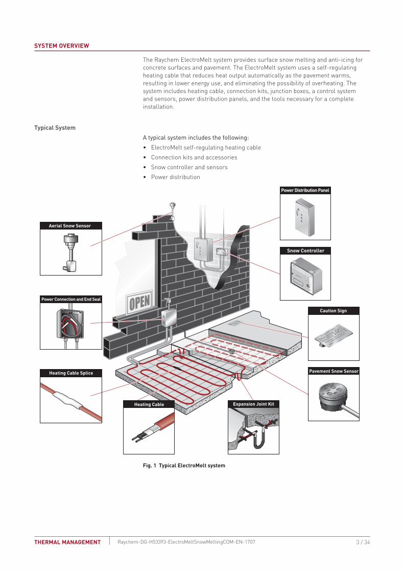
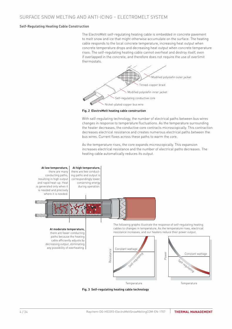
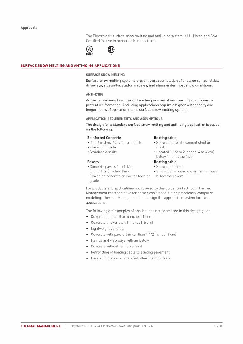
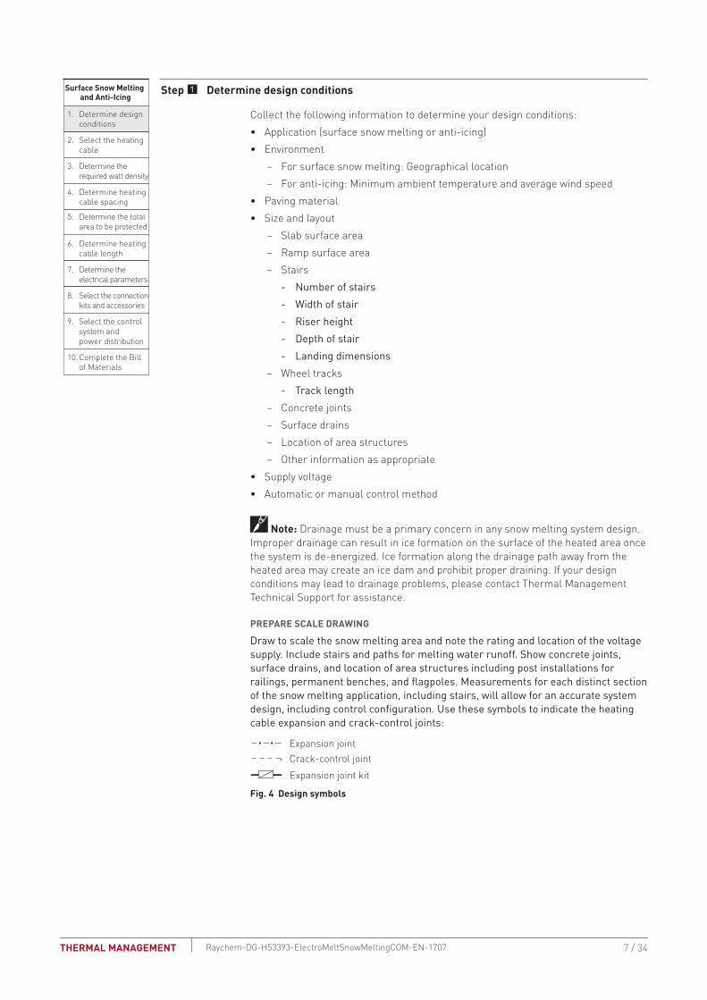
Surface Snow Melting and Anti-Icing
1 Determine design conditions
2 Select the heating cable
3 Determine the required watt density
4 Determine heating cable spacing
5 Determine the total area to be protected
9 Select the control system and power distribution
6 Determine heating cable length
7 Determine the electrical parameters
8 Select the connection kits and accessories
10 Complete the Bill of Materials
Step Determine design conditions
Collect the following information to determine your design conditionsbull Application (surface snow melting or anti-icing)bull Environment
ndash For surface snow melting Geographical location ndash For anti-icing Minimum ambient temperature and average wind speed
bull Paving materialbull Size and layout
ndash Slab surface area ndash Ramp surface area ndash Stairs
- Number of stairs - Width of stair - Riser height - Depth of stair - Landing dimensions
ndash Wheel tracks - Track length
ndash Concrete joints ndash Surface drains ndash Location of area structures ndash Other information as appropriate
bull Supply voltagebull Automatic or manual control method
Note Drainage must be a primary concern in any snow melting system design Improper drainage can result in ice formation on the surface of the heated area once the system is de-energized Ice formation along the drainage path away from the heated area may create an ice dam and prohibit proper draining If your design conditions may lead to drainage problems please contact Thermal Management Technical Support for assistance
PREPARE SCALE DRAWING
Draw to scale the snow melting area and note the rating and location of the voltage supply Include stairs and paths for melting water runoff Show concrete joints surface drains and location of area structures including post installations for railings permanent benches and flagpoles Measurements for each distinct section of the snow melting application including stairs will allow for an accurate system design including control configuration Use these symbols to indicate the heating cable expansion and crack-control joints
S
Power connectionEnd seal
Splice
Expansion jointCrack-control joint
Expansion joint kit
E
P
Fig 4 Design symbols
7 34THERMAL MANAGEMENT Raychem-DG-H53393-ElectroMeltSnowMeltingCOM-EN-1707
Example Surface Snow Melting SystemApplication Surface snow meltingGeographical location Buffalo NYSize and layout 80 ft x 50 ft (244 m x 152 m)Paving material Concrete slabStairs
Number of stairs 10Width of stair 5 ft (15 m)Riser height 6 in (15 cm)Depth of stair 12 in (30 cm)
Supply voltage 277 VPhase Single-phaseControl method Automatic snow melting controller
Example Anti-Icing SystemApplication Anti-icingMinimum ambient temperature 10degF (ndash12degC)Average wind speed 20 mph (32 kmph)Size and layout 80 ft x 50 ft (244 m x 152 m)Paving material Concrete slabStairs
Number of stairs 10Width of stair 5 ft (15 m)Riser height 6 in (20 cm)Depth of stair 12 in (30 cm)
Supply voltage 277 VPhase Single-phaseControl method Slab sensing thermostat
Surface Snow Melting and Anti-Icing
1 Determine design conditions
2 Select the heating cable
3 Determine the required watt density
4 Determine heating cable spacing
5 Determine the total area to be protected
9 Select the control system and power distribution
6 Determine heating cable length
7 Determine the electrical parameters
8 Select the connection kits and accessories
10 Complete the Bill of Materials
Step Select the heating cable
Thermal Management offers the option of two self-regulating heating cables with the ElectroMelt system Cable selection is independent of application and depends only upon supply voltage ElectroMelt heating cables must only be powered by single phase voltage In applications where the power supply is three-phase all circuits must be wired to provide single-phase voltage to the heating cables Select the appropriate cable based on the supply voltage available for the application area
TAbLE 1 ELECTROMELT SELF-REGULATING HEATING CAbLESupply voltage Catalog number208 V 240 V 277 V EM2-XR
Example Surface Snow Melting SystemSupply voltage 277 V (from Step 1)Heating cable EM2-XR
Example Anti-Icing SystemSupply voltage 277 V (from Step 1)Heating cable EM2-XR
SURFACE SNOW MELTING AND ANTI-ICING ndash ELECTROMELT SYSTEM
8 34 THERMAL MANAGEMENTRaychem-DG-H53393-ElectroMeltSnowMeltingCOM-EN-1707
Surface Snow Melting and Anti-Icing
1 Determine design conditions
2 Select the heating cable
3 Determine the required watt density
4 Determine heating cable spacing
5 Determine the total area to be protected
9 Select the control system and power distribution
6 Determine heating cable length
7 Determine the electrical parameters
8 Select the connection kits and accessories
10 Complete the Bill of Materials
Step Determine the required watt density
SURFACE SNOW MELTING
For maximum performance from any snow melting system you must first take into account the local snowfall and icing patterns A system design that works well in one city may be inadequate in another The energy required to melt snow varies with air temperature wind speed relative humidity snow density and the depth of the snow on the pavement
Table 2 summarizes the required watt density for most major cities in North America based on typical minimum ambient temperatures and the snowfall and icing patterns Select the city from the list or closest city where similar climatic conditions exist
TAbLE 2 REQUIRED WATT DENSITY FOR SURFACE SNOW MELTINGWattsft2 Wattsm2
City Concrete Pavers Concrete PaversUSABaltimore MD 35 40 377 431 Boston MA 35 40 377 431 Buffalo NY 40 45 431 484 Chicago IL 35 40 377 431 Cincinnati OH 35 40 377 431 Cleveland OH 35 40 377 431 Denver CO 35 40 377 431 Detroit MI 35 40 377 431 Great Falls MT 50 50 538 538 Greensboro NC 35 35 377 377 Indianapolis IN 35 40 377 431 Minneapolis MN 50 50 538 538 New York NY 35 40 377 431 Omaha NE 45 50 484 538 Philadelphia PA 35 40 377 431 Salt Lake City UT 35 35 377 377 Seattle WA 35 35 377 377 St Louis MO 35 40 377 431 CanadaCalgary AB 45 45 484 484 Edmonton AB 50 50 538 538 Fredericton NB 40 45 431 484 Halifax NS 35 40 377 431 Moncton NB 40 40 431 431 Montreal QC 45 45 484 484 Ottawa ON 45 45 484 484 Prince George BC 50 55 538 592 Quebec QC 45 45 484 484 Regina SK 50 55 538 592 Saskatoon SK 50 50 538 538 St John NB 40 45 431 484 St Johnrsquos NF 35 35 377 377 Sudbury ON 40 45 431 484 Thunder Bay ON 50 55 538 592 Toronto ON 35 40 377 431 Vancouver BC 35 40 377 431 Winnipeg MB 50 55 538 592
Note To provide faster heat-up the required watt density in Table 2 is greater than what is suggested by ASHRAE
9 34THERMAL MANAGEMENT Raychem-DG-H53393-ElectroMeltSnowMeltingCOM-EN-1707
Example Surface Snow Melting SystemGeographical location Buffalo NY (from Step 1)Required watt density 40 Wft2 (431 Wm2) (from Table 2)
ANTI-ICINGFrom the minimum ambient temperature and average wind speed that you determined in Step 1 for your anti-icing application use the tables below to determine the required watt density for that application
TAbLE 3 REQUIRED WATT DENSITY FOR ICE-FREE SURFACES WFT2
Minimum ambient temperature Average wind speed during freezing periodsdegF 5 mph 10 mph 15 mph 20 mph
20degF 30 30 35 4010degF 30 30 35 45
0degF 30 40 45 60ndash10degF 30 45 60 80ndash20degF 35 55 80 ndashndash30degF 40 65 ndash ndashndash40degF 45 75 ndash ndash
TAbLE 4 REQUIRED WATT DENSITY FOR ICE-FREE SURFACES WM2 Minimum ambient temperature Average wind speed during freezing periodsdegC 8 kmph 16 kmph 24 kmph 32 kmphndash7degC 323 323 377 431ndash12degC 323 323 377 484ndash18degC 323 431 484 646ndash23degC 323 484 646 861ndash29degC 377 592 861 ndashndash34degC 431 699 ndash ndashndash40degC 484 807 ndash ndash
Note This procedure is derived from finite model studies of 4-inch slabs and is applicable to standard concrete pavement from 4 to 6 inches thick placed directly on grade If your application involves other materials or construction contact your Thermal Management representative
Example Anti-Icing SystemMinimum ambient temperature 10degF (ndash12degC) (from Step 1)Average wind speed 20 mph (32 kmph) (from Step 1)Required watt density 45 Wft2 (484 Wm2) (from Table 3 and Table 4)
SURFACE SNOW MELTING AND ANTI-ICING ndash ELECTROMELT SYSTEM
10 34 THERMAL MANAGEMENTRaychem-DG-H53393-ElectroMeltSnowMeltingCOM-EN-1707
Surface Snow Melting and Anti-Icing
1 Determine design conditions
2 Select the heating cable
3 Determine the required watt density
4 Determine heating cable spacing
5 Determine the total area to be protected
9 Select the control system and power distribution
6 Determine heating cable length
7 Determine the electrical parameters
8 Select the connection kits and accessories
10 Complete the Bill of Materials
Step Determine heating cable spacing
SURFACES
To determine your heating cable spacing you need to know your applicationsrsquos power output and required watt density
The power output from the ElectroMelt heating cable depends on the supply voltage used in the application Table 5 lists power output per linear foot of heating cable determined by the supply voltage Divide this figure by the required watt density that you determined in Step 3 You will get the required heating cable spacing in feet or meters as applicable Multiply this figure by 12 inches or by 100 centimeters to determine your heating cable spacing
TAbLE 5 HEATING CAbLE SPACING IN CONCRETESupply voltage Catalog number Power output Wft (Wm)208 V EM2-XR 30 (98)240 V EM2-XR 32 (105)277 V EM2-XR 34 (112)
To determine cable spacing required for surface snow melting and anti-icing
Heating cable spacing (in) = (Wft power output of cable per Table 5) x 12 in
Wft2 requirement from Step 3
Heating cable spacing (cm) = (Wm power output of cable per Table 5) x 100 cm
Wm2 requirement from Step 3
Round answer to nearest whole number of inches or centimeters
Example Surface Snow Melting SystemSupply voltage 277 V (from Step 1)Heating cable EM2-XR (from Step 2)Power output 34 Wft (112 Wm2) (from Table 5)Spacing (34 Wft x 12 in) 40 Wft2 = 102 in Rounded to 10 in (112 Wm x 100 cm) 431 Wm2 = 26 cm
Example Anti-Icing System Supply voltage 277 V (from Step 1)Heating cable EM2-XR (from Step 2)Power output 34 Wft (from Table 5)Spacing (34 Wft x 12 in) 45 Wft2 = 91 in Rounded to 9 in (112 Wm x 100 cm) 484 wm2 = 231 cm Rounded to 23 cm
11 34THERMAL MANAGEMENT Raychem-DG-H53393-ElectroMeltSnowMeltingCOM-EN-1707
STAIRSHeat loss in stairs occurs from the two exposed surfaces the top of the stair and its side Watt density requirements are therefore greater for snow melting and anti-icing Rather than calculating heating cable spacing in the stair refer to Table 6 and determine the number of runs of heating cable per stair based on the depth of the stair Space the heating cable evenly across the depth of the stair with one run 2 in (5 cm) from the front or nose of the stair This method will provide sufficient watt density for both snow melting and anti-icing
TAbLE 6 HEATING CAbLE RUNS PER STAIRStair depth Number of cable runs per stairLess than 105 in (27 cm) 2105ndash12 in (27ndash30 cm) 3
For landings in the stairway use cable spacing as calculated for surfaces As with stairs a run of heating cable must be placed 2 in (5 cm) from the exposed edge of the landing leading to the stairs
Anticipate and design for the addition of railings or other follow on construction that will require cutting or drilling into the concrete as damage to installed heating cable may occur Allow for at least 4 inches clearance between the heating cable and any planned cuts or holes
Example Surface Snow Melting and Anti-Icing SystemDepth of stair 12 in (30 cm) (from Step 1)Number of cable runs per stair 3 runsSpacing Equally spaced across the width of the stair with one run 2 in (5 cm) from the front edge
6 in
Riser height (15 cm)
12 inStair
depth
(30 cm)
5 ft (15 m)
Width
3 ftLanding depth
(09 m)
Junctionbox
Fig 5 Typical heating cable layout for concrete stairs
SURFACE SNOW MELTING AND ANTI-ICING ndash ELECTROMELT SYSTEM
12 34 THERMAL MANAGEMENTRaychem-DG-H53393-ElectroMeltSnowMeltingCOM-EN-1707
Surface Snow Melting and Anti-Icing
1 Determine design conditions
2 Select the heating cable
3 Determine the required watt density
4 Determine heating cable spacing
5 Determine the total area to be protected
9 Select the control system and power distribution
6 Determine heating cable length
7 Determine the electrical parameters
8 Select the connection kits and accessories
10 Complete the Bill of Materials
Step Determine the total area to be protected
SURFACES
To determine the total amount of heating cable you need to determine the surface area you will be protecting from snow and ice accumulation If assistance is required in designing for irregular shaped areas please contact your Thermal Management representative
Example Surface Snow Melting SystemTotal area of concrete slab 80 ft x 50 ft = 4000 ft2 (244 m x 152 m = 3708 rounded to = 371 m2)
Example Anti-Icing SystemTotal area of concrete slab 80 ft x 50 ft = 4000 ft2 (244 m x 152 m = 3708 rounded to = 371 m2)
WHEEL TRACKS
To reduce power consumption for concrete driveways it may be sufficient to provide snow melting for only the wheel tracks
Design wheel track applications with the same spacing used for concrete slabs Heating cable should run to the edge of each side of the wheel track and be laid in a serpentine pattern along the length of the wheel track
Cable in 6 in minimum(15 cm) from edge unless curbs used
66 (2 m) typ
Structurally sound well-drained base designed tohandle expected load andenvironmental conditions
Fig 6 Wheel track example
STAIRS
Surface area of the stairs is not required to determine heating cable required
13 34THERMAL MANAGEMENT Raychem-DG-H53393-ElectroMeltSnowMeltingCOM-EN-1707
Surface Snow Melting and Anti-Icing
1 Determine design conditions
2 Select the heating cable
3 Determine the required watt density
4 Determine heating cable spacing
5 Determine the total area to be protected
9 Select the control system and power distribution
6 Determine heating cable length
7 Determine the electrical parameters
8 Select the connection kits and accessories
10 Complete the Bill of Materials
Step Determine heating cable length
SURFACESCalculate the heating cable length by dividing the total heated area by the heating cable spacing calculated in the previous steps In Step 8 you will need to add additional heating cable for connection kits and end terminations which will then give you the total heating cable length Calculate the heating cable length for the surface as follows
Heating cable length = Heated area (ft2) x 12
Heating cable spacing (in)
Heated area (m2) x 100
Heating cable spacing (cm)
Example Surface Snow Melting System for Concrete SlabTotal area of concrete slab 4000 ft2 (371 m2) (from Step 5)Cable spacing 10 in (26 cm) (from Step 4) (4000 ft2 x 12 in) 10 in spacing = 4800 ft (371 m2 x 100 cm) 26 cm spacing = 1427 mHeating cable length 4800 ft (1427 m)
Example Anti-Icing System for Concrete SlabTotal area of concrete slab 4000 ft2 (371 m2) (from Step 5)Cable spacing 9 in (23 cm) (from Step 4) (4000 ft2 x 12 in) 9 in spacing = 5333 ft (371 m2 x 100 cm) 23 cm spacing = 1613 mHeating cable length 5333 ft (1613 m)
SURFACE SNOW MELTING AND ANTI-ICING ndash ELECTROMELT SYSTEM
14 34 THERMAL MANAGEMENTRaychem-DG-H53393-ElectroMeltSnowMeltingCOM-EN-1707
STAIRS
6 in
Riser height(15 cm)
12 inStair depth
(30 cm)
5 ft (15 m)
Width
3 ftLanding depth
(09 m)
Junctionbox
Fig 7 Concrete stair example
Use the formula below to determine the length of cable required for stairs Stair area is not needed for the cable length calculation Two or three runs of heating cable will be installed per stair as determined in Step 3 For landing areas use the equation for surfaces
Length of cable for stair (ft) (m)
No of stairs = x [(No runs per stair x width of stair) + (2 x riser height)]
Example Surface Snow Melting and Anti-Icing System for StairsNumber of stairs 10 stairs (from Step 1)Number of cable runs per stair 3 runsWidth of stair 5 ft (15 m) (from Step 1)Riser height 6 in (15 cm) convert to 05 ft (015 m) (from Step 1) 10 stairs x [(3 x 5 ft) + (2 x 05 ft)] = 160 ft 10 stairs x [(3 x 15 m) + (2 x 015 m)] = 48 mHeating cable length 160 ft (48 m)
For applications where the landing area is very large or where an expansion joint exists between the stairs and landing consider the stairs and landing as two separate areas In these cases determine the length of cable required for the stairs as shown earlier in this section and select the cable for the landing as shown for ramps slabs driveways sidewalks platform scales
15 34THERMAL MANAGEMENT Raychem-DG-H53393-ElectroMeltSnowMeltingCOM-EN-1707
Surface Snow Melting and Anti-Icing
1 Determine design conditions
2 Select the heating cable
3 Determine the required watt density
4 Determine heating cable spacing
5 Determine the total area to be protected
9 Select the control system and power distribution
6 Determine heating cable length
7 Determine the electrical parameters
8 Select the connection kits and accessories
10 Complete the Bill of Materials
Step Determine the electrical parameters
This section will help you determine the electrical parameters for an ElectroMelt system including circuit breaker sizing and maximum circuit length Total required heating cable length divided by maximum circuit length will determine the number of circuits required for your snow melting solution
DETERMINE MAXIMUM CIRCUIT LENGTH
To determine maximum circuit length it is important to establish a minimum startup temperature for the system The following tables provide maximum circuit lengths based on minimum startup temperature circuit breaker rating and supply voltage Colder temperature startup requires shorter maximum circuit lengths The use of an automatic system which energizes the system above 20degF (ndash7degC) ensures that you can use maximum circuit lengths Manual control systems may require you to use shorter circuit lengths to compensate for startup below 20degF (ndash7degC)
A 30-mA ground-fault protection device (GFPD) must be used to provide protection from arcing or fire and to comply with warranty requirements agency certifications and national electrical codes If the heating cable is improperly installed or physically damaged sustained arcing or fire could result If arcing does occur the fault current may be too low to trip conventional circuit breakers
TAbLE 7 MAXIMUM CIRCUIT LENGTH FOR STARTUP AT 20degF (ndash7degC) IN FEET (METERS) USING AN AUTOMATIC SNOW CONTROL SYSTEM
Circuit breaker (A)
Heating cable supply voltage 208 V 240 V 277 V
15 80 (24) 85 (26) 100 (31)20 105 (32) 115 (35) 130 (40)30 160 (49) 170 (52) 195 (59)40 210 (64) 230 (70) 260 (79)50 265 (81) 285 (87) 325 (99)
TAbLE 8 MAXIMUM CIRCUIT LENGTH FOR STARTUP AT 0degF (ndash18degC) IN FEET (METERS) USING A MANUAL CONTROL SYSTEM
Circuit breaker (A)
Heating cable supply voltage 208 V 240 V 277 V
15 75 (23) 80 (24) 90 (27)20 100 (31) 110 (34) 120 (37)30 145 (44) 160 (49) 180 (55)40 200 (61) 210 (64) 240 (73)50 245 (75) 265 (81) 300 (91)
WARNING To minimize the danger of fire from sustained electrical arcing if the heating cable is damaged or improperly installed and to comply with the requirements of Thermal Management agency certifications and national electrical codes ground-fault equipment protection must be used on each heating cable branch circuit Arcing may not be stopped by conventional circuit protection
Example Surface Snow Melting and Anti-Icing System with Automatic Snow ControlStartup temperature 20degF (ndash7degC) (from Step 1)Circuit breakers 50 ASupply voltage 277 V (from Step 1)Maximum circuit length 325 ft (99 m) (from Table 7)
SURFACE SNOW MELTING AND ANTI-ICING ndash ELECTROMELT SYSTEM
16 34 THERMAL MANAGEMENTRaychem-DG-H53393-ElectroMeltSnowMeltingCOM-EN-1707
DETERMINE NUMbER OF CIRCUITS Use the following formula to determine number of circuits for the system
Number of circuits = Heating cable length required
Maximum heating cable circuit length
Example Surface Snow MeltingSurfacesTotal heating cable length 4800 ft (1427 m) (from Step 6)Maximum circuit length 325 ft (99 m) (from above)Number of circuits 4800 325 = 148 rounded to 15 circuitsStairsTotal heating cable length 160 ft (48 m) (from Step 6)Maximum circuit length 325 ft (99 m) (from above)Number of circuits 160 325 = 05 rounded to 1 circuit
Example Anti-Icing SystemSurfacesTotal heating cable length 5333 ft (1613 m) (from Step 6)Maximum circuit length 325 ft (99 m)Number of circuits 5333 325 = 164 rounded to 17 circuitsStairsTotal heating cable length 160 ft (48 m) (from Step 6)Maximum circuit length 325 ft (99 m) (from above)Number of circuits 160 325 = 05 rounded to 1 circuit
DETERMINE TRANSFORMER LOADThe total transformer load is the sum of load on all the circuit breakers in the system
Calculate the Circuit breaker Load (CbL) as
CBL (kW) = Circuit breaker rating (A) x 08 x Supply voltage
1000
Calculate the Total Transformer Load as follows
If the CBL is equal on all circuit breakers calculate the Total Transformer Load as
Total Transformer Load (kW) = CBL x Number of circuits
If the CBL is not equal on all circuit breakers calculate the Total Transformer Load as
Total Transformer Load (kW) = CBL1 + CBL2 + CBL3+ CBLN
17 34THERMAL MANAGEMENT Raychem-DG-H53393-ElectroMeltSnowMeltingCOM-EN-1707
Example Surface Snow MeltingCircuit breaker load (50 A x 08 x 277 V) 1000 = 111 kWTransformer Load 111 kW x 16 circuits = 1776 kW rounded to 178 kW 178 kW
Example Anti-Icing SystemCircuit breaker load (50 A x 08 x 277 V) 1000 = 111 kWTransformer load 111 kW x 18 circuits = 1998 kW rounded to 200 kW 200 kW
Surface Snow Melting and Anti-Icing
1 Determine design conditions
2 Select the heating cable
3 Determine the required watt density
4 Determine heating cable spacing
5 Determine the total area to be protected
9 Select the control system and power distribution
6 Determine heating cable length
7 Determine the electrical parameters
8 Select the connection kits and accessories
10 Complete the Bill of Materials
Step Select the connection kits and accessories
Thermal Management provides all the connection kits and accessories necessary to satisfy code approval agency and warranty requirements for the ElectroMelt system Additional heating cable will be required for connection kits and end terminations Adding the additional heating cable allowances needed with the heating cable length required for the layout will give you the total heating cable length required
Prepare a drawing of your system showing distinct circuits layout of cables connection kits expansion joints drains heated pathways for meltwater power connections junction boxes and sensors Determine length of cable from slab for power connection for all circuits If possible avoid crossing expansion crack control or other pavement joints Use the EMK-XEJ expansion joint kit to protect the heating cable if crossing is unavoidable
Junction boxes must be mounted above grade to prevent water entry Use an EMK-XJB or equivalent UL Listed or CSA Certified weatherproof junction box Protect heating cable from slab to junction box inside individual 1-inch rigid metal conduits Do not penetrate floors or walls with conduit nor insulate the conduit
SURFACE SNOW MELTING AND ANTI-ICING ndash ELECTROMELT SYSTEM
18 34 THERMAL MANAGEMENTRaychem-DG-H53393-ElectroMeltSnowMeltingCOM-EN-1707
TAbLE 9 CONNECTION KITS AND ACCESSORIESCatalog number Description
Standard packaging Usage
Heating cable allowance 1
Connection Kits
Power connection EMK-XP
End seal EMK-XP
EMK-XP Power connection and end seal kit
1 1 per circuit 3 ft (1 m) for connection plus conduit length for power connection and conduit length for end seal
EMK-XS Splice kit 1 As required 1 ft (30 cm)
Accessories
EMK-XJR Jacket repair kit 1 As required ndash
EMK-CT Nylon cable ties 100pack 1 per foot of cable used
ndash
EMK-XT Crimping tool 1 ndash ndash
SMCS Snow melt caution sign Dimensions 6 x 4 in (150 x 100 mm)
1 1 minimum per system
ndash
EMK-XEJ Expansion joint kit 1 1 per expansion joint crossing
1 12 ft (45 cm)
EMK-XJB Junction boxDimensions 15 12 x 11 34 x 7 58 in (394 x 299 x 194 mm)
1 1ndash2 ft (30ndash60 cm) for each end in the junction box
Maximum of two circuits per EMK-XJB
1 Allow extra heating cable for ease of component installation
19 34THERMAL MANAGEMENT Raychem-DG-H53393-ElectroMeltSnowMeltingCOM-EN-1707
Example Surface Snow Melting SystemNumber of circuits 15 for concrete slab + 1 for stairs = 16Power connection kits 16 power connection kitsConduit length (from slab to junction box) Power connection 15 ft (45 m) End seal 15 ft (45 m) (15 ft + 15 ft) x 16 circuits = 480 ft (45 m + 45 m) x 16 circuits = 144 mHeating cable allowance for each power connection 3 ft x 16 circuits = 48 ft 1 m x 16 circuits = 16 mTotal heating cable length required 528 ft (160 m)
Example Anti-Icing SystemNumber of circuits 17 for concrete slab + 1 for stairs = 18Power connection kits 18 power connection kitsConduit length (from slab to junction box) Power connection 15 ft (45 m) End seal 15 ft (45 m) (15 ft + 15 ft) x 18 circuits = 540 ft (45 m + 45 m) x 18 circuits = 162 mHeating cable allowance for each power connection 3 ft x 18 circuits = 54 ft 1 m x 18 circuits = 18 mTotal heating cable length required 594 ft (180 m)
SURFACE SNOW MELTING AND ANTI-ICING ndash ELECTROMELT SYSTEM
20 34 THERMAL MANAGEMENTRaychem-DG-H53393-ElectroMeltSnowMeltingCOM-EN-1707
Surface Snow Melting and Anti-Icing
1 Determine design conditions
2 Select the heating cable
3 Determine the required watt density
4 Determine heating cable spacing
5 Determine the total area to be protected
9 Select the control system and power distribution
6 Determine heating cable length
7 Determine the electrical parameters
8 Select the connection kits and accessories
10 Complete the Bill of Materials
Step Select the control system and power distribution
CONTROL SYSTEMS
Select a control system from the following three options but keep in mind that an automatic snow controller offers the highest system efficiency and the lowest operating cost bull Manual onoff controlbull Slab sensing thermostatbull Automatic snow melting controller
If the current rating of the control means is exceeded all three methods will require contactors sized to carry the load Each method offers a tradeoff balancing initial cost versus energy efficiency and ability to provide effective snow melting If the system is not energized when required snow will accumulate If the system is energized when it is not needed there will be unnecessary power consumption Choose the control method that best meets the project performance requirements For additional information refer to the ldquoTypical Control Diagramsrdquo Table 7 or contact your Thermal Management representative for details
Manual OnOff ControlA manually controlled system is operated by a switch that controls the system power contactor This method requires constant supervision to work effectively A manual system can be controlled by a building management system
Slab Sensing ThermostatA slab sensing thermostat can be used to energize the system whenever the slab temperature is below freezing but is not energy efficient when used as the sole means of control The slab sensing thermostat is recommended for all snow melting applications even when an automatic snow controller is used and is required for all asphalt and paver installations (for asphalt it prevents surface damage due to overheating)
Automatic Snow Melting ControllerWith an automatic snow controller the snow melting system is automatically energized when both precipitation and low temperature are detected When precipitation stops or the ambient temperature rises above freezing the system is de-energized In addition a slab sensor de-energizes the system after the slab reaches the slab sensing set point even if freezing precipitation is still present Using an automatic snow controller with a slab sensor offers the most energy-efficient control solution
For areas where a large number of circuits are required the Raychem ACS-30 can be used The Surface Snow Melting control mode in the ACS-30 includes an External Device control option This option allows a SnowMoisture sensing controller (from Table 10) to be integrated into the ACS-30 system Note that sensors (snow or gutter) cannot be directly connected to the ACS-30 system Refer to the ACS-30 Programming Guide (H58692) for more information on system setup
21 34THERMAL MANAGEMENT Raychem-DG-H53393-ElectroMeltSnowMeltingCOM-EN-1707
CIT-1snow sensor
To power supply or incorporate the ETI snow melting control system into a power distribution panel
APS-4C (shown) with SC-40C satelllitecontactor or APS-3C snow controller
OptionalSC-40Csatellite contactor
To additionalSC-40C satellitecontactors
To heating cable(s)
To heating cable(s)
Optional RCU-3 or RCU-4 remote control unit
To power supply
SIT-6E pavement mounted sensor
Environmental Technology Inc (ETI) of South Bend Indiana offers a complete line of automatic controllers for snow melting applications
Fig 8 Automatic snow melting control system
TAbLE 10 CONTROL SYSTEMS Catalog number Description
Slab Sensing ThermostatECW-GF Electronic ambient sensing controller with 30-mA ground-fault protection The control-
ler can be programmed to maintain temperatures up to 200degF (93degC) at voltages from 100 to 277 V and can switch current up to 30 Amperes The ECW-GF is complete with a 25-ft (76-m) temperature sensor and is housed in a Type 4X rated enclosure The controller features an ACDC dry alarm contact relay
An optional ground-fault display panel (ECW-GF-DP) that can be added to provide ground-fault or alarm indication in applications where the controller is mounted in inaccessible locations
ECW-GF-DP An optional remote display panel (ECW-GF-DP) can be added to provide ground-fault or alarm indication in applications where the controller is mounted in inaccessible locations
HEATER CYCLE
PD Pro Automatic snow and ice melting controller for pavement sidewalks loading docks roofs gutters and downspouts in commercial and residential environments The PD Pro interfaces with up to two sensors (any combination of CIT-1 GIT-1 or SIT-6E) to meet site requirements The PD Pro is housed in an environmentally-sheltered Type 4X enclosure and weighs only 3 pounds
GF Pro Automatic snow and ice melting controller for pavement sidewalks loading docks roofs gutters and downspouts in commercial and residential environments The GF Pro interfaces with up to two sensors (any combination of CIT-1 GIT-1 or SIT-6E) to meet site requirements The GF Pro is housed in an environmentally-sheltered Type 4X enclosure and weighs only 3 pounds
Features a built-in 30 mA self-testing Ground-Fault Equipment Protection (GFEP) capability digitally filtered to minimize false tripping A ground-fault alarm must be manually reset using the TestReset switch before heater operation can continue
SURFACE SNOW MELTING AND ANTI-ICING ndash ELECTROMELT SYSTEM
22 34 THERMAL MANAGEMENTRaychem-DG-H53393-ElectroMeltSnowMeltingCOM-EN-1707
TAbLE 10 CONTROL SYSTEMS Catalog number Description
Automatic Snow Melting ControllersAPS-3C Automatic snow melting controller housed in a Type 3R enclosure provides effective
economical automatic control of all snow melting applications Features include 120 V or 208ndash240 V models 24-A DPDT output relay and an adjustable hold-on timer
Enclosure dimensions 11-12 in x 9-18 in x 6-916 in (292 mm x 232 mm x 167 mm)
APS-4C Automatic snow melting controller housed in a Type 3R enclosure provides effective economical automatic control of all snow melting applications The APS-4C can oper-ate with any number of SC-40C satellite contactors for larger loads Features include 277 V single-phase or 208ndash240 277480 and 600 V three-phase models built-in 3-pole contactor integral 30 mA ground-fault circuit interrupter and an adjustable hold-on timer
Enclosure dimensions 11-12 in x 9-18 in x 6-916 in (292 mm x 232 mm x 167 mm)
SC-40C Satellite contactor power control peripheral for an APS-4C snow melting control-ler housed in a Type 3R enclosure Features include 277 V single-phase or 208ndash240 277480 and 600 V three-phase models built-in 3-pole contactor and integral 30 mA ground-fault circuit interrupter
Enclosure dimensions 11-12 in x 9-18 in x 6 in (292 mm x 232 mm x 152 mm)
Snow Melting and Gutter De-Icing Sensors and Accessories
CIT-1 Overhead snow sensor that detects precipitation or blowing snow at ambient temper-atures below 38degF (33degC) For use with either an APS-3C or APS-4C automatic snow melting controller
SIT-6E Pavement-mounted sensor signals for the heating cable to turn on when the pavement temperature falls below 38degF (33degC) and precipitation in any form is present Microcontroller technology effectively eliminates ice bridging while ensuring accurate temperature measurement For use with either an APS-3C or APS-4C automatic snow melting controller
RCU-3 The RCUndash3 provides control and status display to the APSndash3C controller from a remote location It has a 2 4 6 or 8 hour CYCLE TIME adjustment independent of APS-3C setting
RCU-4 The RCUndash4 provides control and status display to the APSndash4C controller and SC-40C Satellite Contactor from a remote location It has a 2 4 6 or 8 hour CYCLE TIME adjustment independent of the APS-4C or SC-40C setting
23 34THERMAL MANAGEMENT Raychem-DG-H53393-ElectroMeltSnowMeltingCOM-EN-1707
TAbLE 10 CONTROL SYSTEMS Catalog number Description
Electronic Controllers
ACS-UIT2ACS-PCM2-5
The Raychem ACS-30 Advanced Commercial Control System is a multipoint electronic control and monitoring system for heat-tracing used in various commercial applications such as pipe freeze protection roof and gutter de-icing surface snow melting hot water temperature maintenance and floor heating The Raychem ACS-30 system can control up to 260 circuits with multiple networked ACS-PCM2-5 panels with a single ACS-UIT2 user interface terminal The ACS-PCM2-5 panel can directly control up to 5 individual heat-tracing circuits using electromechanical relays rated at 30 A up to 277 V
By FieldServer TechnologieswwwProtoCessorcom
PROTOCESSORSERIAL ETHERNET
PROTONODE
FRAME GND- PWR+PWR
RS 485+RS 485 -RS 485 GND
S3S2S1S0B3B2B1B0
A7A6A5A4A3A2A1A0
ProtoNode-RER The Raychem ProtoNode is an external high performance multi-protocol gateway for customers needing protocol translation between Building Management Systems (BMS) and the Raychem ACS-30 or C910-485 controllers
The ProtoNode-RER is for BACnetreg or Metasysreg N2 systems
RTD-200 RTD10CSRTD50CS
Stainless steel jacketed three-wire RTD (Resistance Temperature Detector) used with Raychem C910-485 and ACS-30 controllers
RTD-200 3-in (76 mm) temperature sensor with a 6-ft (18 m) lead wire and 12-in NPT bushing
RTD10CS temperature sensor with a 10-ft (3 m) flexible armor 18-in (457 mm) lead wire and 12-inch NPT bushing
RTD50CS temperature sensor with a 50-ft (3 m) flexible armor 18-in (457 mm) lead wire and 12-in NPT bushing
POWER DISTRIbUTION
Single Circuit ControlHeating cable circuits that do not exceed the current rating of the selected temperature control can be switched directly (see Fig 9)
Group ControlIf the current draw exceeds the switch rating or if the controller will activate more than one circuit or group control an external contactor must be used (see Fig 9)
Large systems with many circuits should use an SMPG power distribution panel The SMPG is a dedicated power-distribution control ground-fault protection monitoring and alarm panel for surface snow melting and anti-icing applications This enclosure contains an assembled circuit-breaker panelboard Panels are equipped with ground-fault circuit breakers with or without alarm contacts The group control package allows the system to operate automatically in conjunction with an ambient-sensing thermostat individual electronic or duty cycle controller
SURFACE SNOW MELTING AND ANTI-ICING ndash ELECTROMELT SYSTEM
24 34 THERMAL MANAGEMENTRaychem-DG-H53393-ElectroMeltSnowMeltingCOM-EN-1707
Single circuit control Group control
Temperaturecontroller
1-poleGFEP breaker
1N
G
Heatingcable
oslashoslash supply
C
Temperaturecontroller
Contactor
1-poleGFEP breaker
N
G (Typ 3)
oslash2
oslash1
oslash3
3-phase 4-wiresupply (WYE)
3-pole mainbreaker
oslash
oslash 1 supply
N
Heating cable sheath braid or ground
Heating cable sheath braid or ground
Fig 9 Single circuit and group control
Exterior View Interior View
NP
NP
NP
NP
G
NP
NP
G
NP
R
NP
Nameplate
Mounting brackets
Heater thermostat(3R only)
Power on lightHTC energized light
CB tripped alarm
Heater (3R only)
Door lock handle
SnowIcemelt controller
Ground bar
Panelboardlugs
Control wiring
Heater cycle atimed control
EUR - 5A
Main breaker(optional)
Heat tracecontactor
Branch breakers(2 pole)
Panelboard
Fig 10 SMPG1 power distribution panel
N
Three-pole main contactor
FuseMain circuit breaker (optional)
Incomingpower
GND
24 V
One-pole with 30-mAground-fault trip (277 V)
Remote annunciation alarm(circuit breaker
with alarm type 3)
GIT-1
CIT-1
SIT-6E
Braid
Aerialsnow sensor
Gutterice sensor
Slabtemperature sensor
Pavement-mountedsensor
Single Oslashconnection
SNOWICE
SUPPLY
EUR-5A SNOW SWITCHAUTOMATIC SNOWICE MELTING CONTROL PANEL
HEATER
HEATERCYCLE
HOURS
0
45degF
50degF
55degF
60degF65degF
70degF
75degF
80degF
85degF
2
4 6
8
10
TEMPERATURE
Control transformer
Fig 11 Typical wiring diagram of group control with SMPG1
25 34THERMAL MANAGEMENT Raychem-DG-H53393-ElectroMeltSnowMeltingCOM-EN-1707
TAbLE 11 POWER DISTRIbUTIONCatalog number Description
Power Distribution and Control Panels
NP
NP
NP
NP
NP
NP
NP
SMPG1 Single-phase power distribution panel that includes ground-fault protection monitor-ing and control for snow melting systems Single-phase voltages include 208 and 277 V
If standard configurations do not meet your needs custom SMPG panels are available and processed under the catalog number SMPG-GENERAL part number P000000763 Please contact your Thermal Management representative for a custom SMPG panel quotation
Example Surface Snow Melting SystemThis system has 16 circuits and will require a specially designed control panel As many as eight SIT-6E sensors can be used in this configuration The amount depends upon designer preference
Example Anti-Icing SystemThis system has 18 circuits and will require a specially designed control panel As many as eight SIT-6E sensors can be used in this configuration The amount depends upon designer preference
SURFACE SNOW MELTING AND ANTI-ICING ndash ELECTROMELT SYSTEM
26 34 THERMAL MANAGEMENTRaychem-DG-H53393-ElectroMeltSnowMeltingCOM-EN-1707
Surface Snow Melting amp Anti-Icing
1 Determine design conditions
2 Select the heating cable
3 Determine the required watt density
4 Determine heating cable spacing
5 Determine the total area to be protected
9 Select the control system and power distribution
6 Determine heating cable length
7 Determine the electrical parameters
8 Select the connection kits and accessories
10 Complete the Bill of Materials
Step 0 Complete the bill of Materials
If you used the Design Worksheet to document all your design parameters you should have all the details you need to complete the Bill of Materials
27 34THERMAL MANAGEMENT Raychem-DG-H53393-ElectroMeltSnowMeltingCOM-EN-1707
ELECTROMELT SYSTEM SURFACE SNOW MELTING AND ANTI-ICING DESIGN WORKSHEET
Step Determine design conditions
Application Size and layoutSupply voltage Phase Control method
Surface snow melting Geographical location _____________________
Anti-icing Minimum ambient temperature _____________________ Average wind speed during freezing periods (mphkmph) ____________________
Paving material Concrete pavement In concrete under paving stones
Slab surface (ftm) __________________Ramp surface (ftm) _________________ Stairs Number of stairs ______________ Width of stair (ftm) ______________ Riser height (incm) ______________ Depth of stair (incm) ______________ Landing dimensions (ftm) ______________Wheel tracks Track length (ftm) ____________
208 V
240 V
277 V
Single-phase Manual onoff control Slab-sensing thermostat Automatic snow melting
controller
Example9 Surface snow melting9 buffalo NY9 Concrete slab
Slab surface 80 ft x 50 ftStairs Number of stairs 10 Width of stair 5 ft Riser height 6 in Depth of stair 12 in
9 277 V 9 Single-phase 9 Automatic snow melting controller
Step Select the heating cableSee Table 1 EM2-XR
Example9 EM2-XR
Step Determine the required watt densitySurface snow melting
See Table 2Anti-icing
See Table 3 and Table 4
Geographical location _________________________Required watt density (Wft2)(Wm2) ___________________________
Minimum ambient temperature (degFdegC) _______
Average wind speed during freezing periods (mphkmph) ______
Required watt density (Wft2)(Wm2) _______
ExampleGeographical location buffalo NYRequired watt density 40 Wft2
SURFACE SNOW MELTING AND ANTI-ICING ndash ELECTROMELT SYSTEM
28 34 THERMAL MANAGEMENTRaychem-DG-H53393-ElectroMeltSnowMeltingCOM-EN-1707
Step Determine heating cable spacingSee Table 5
34 Wft
12 in 3
3Equally spaced across the width of the stairwith one run 2 in from the front edge
40 Wft2 10 in
Power output (Wft) Watt density (Wft2)
x( )Heating cable spacing (in)
12 inftPower output (Wft)
Stairs
Surfaces
Surfaces
Calculate the heating cable needed for stairs and landing
Determine the number of cable runs needed
Depth of stair lt105 in (27 cm) 2 cable runs
Depth of stair 105ndash12 in (27ndash30 cm) 3 cable runs
Cable runs needed
Concrete stair depth (incm) Number of cable runs Spacing
StairsCalculate the heating cable needed for stairs and landing
Determine the number of cable runs needed
Depth of stair lt105 in (27 cm) 2 cable runs
Depth of stair 105ndash12 in (27ndash30 cm) 3 cable runs
Cable runs needed
x( )12 inft
=Watt density (Wft2)
Example
Note Round result to the nearest whole number of inches or centimeters
Heating cable spacing (incm)=
Concrete stair depth (incm) Number of cable runs Spacing
Note Round result to the nearest whole number of inches or centimeters
Step Determine the total area to be protected
x80 ft 4000 ft2
Length
50 ft
Width
xSurface area to be protected (ft2m2)Length (ftm) Width (ftm)
=
Example
Surfaces
Surface area to be protected (ft)=
29 34THERMAL MANAGEMENT Raychem-DG-H53393-ElectroMeltSnowMeltingCOM-EN-1707
Step Determine the heating cable length
xHeating cable length for surface
4000 ft2
12 in10 in 4800
Total concrete slab area
Calculate the heating cable for stairs and landing
=Heating cable spacing
x x x =
=
=
=
=
+( () )10
No of stairs
32
No of runs per stair
5 ft
Width of stair
05 ft
Riser height
160 ft
4960 ft
Heating cable length for stairs[ ]
Note Additional heating cable for connection kits and end terminations is calculated in Step 8
Calculate the heating cable for stairs and landing
Surfaces
Surfaces
x x x+( () )No of stairs
2No of runs per stair Width of stair (ftm) Riser height (ftm) Heating cable length for stairs (ftm)
[ ]
Note Additional heating cable for connection kits and end terminations is calculated in Step 8
Example
xHeating cable length for surface (ftm)
12 inTotal concrete slab area (ft2m2)
Heating cable spacing (incm)
Calculate heating cable needed for wheel tracks
x 2 x 4 runsWheel track to be protected (ftm)Length (ftm)
Total heating cable length required (ftm)
Total heating cable length required
SURFACE SNOW MELTING AND ANTI-ICING ndash ELECTROMELT SYSTEM
30 34 THERMAL MANAGEMENTRaychem-DG-H53393-ElectroMeltSnowMeltingCOM-EN-1707
Step Determine the electrical parametersSee Table 7 and Table 8
Number of circuits
4800 ft 325 ft 148 rounded to 15
Heating cable length required for surface =
Maximum heating cable circuit length
Determine number of circults Surfaces
Number of circuitsHeating cable length required for surface (ftm) =
Maximum heating cable circuit length (ftm)
Determine number of circults
Circuit breaker load (kW)08 1000
Circuit breaker rating (Amps )x x ( ) =
Supply voltage
Determine total transformer load
Calculate the total transformer load as follows
Calculate circuit breaker load (CBL)
If the CBL is equal on all circuits calculate the transformer load as
If the CBL is NOT equal on all circuits calculate the transformer load as
Total transformer load (kW)Circuit breaker load (kW)x =
Number of breakers
Total transformer load (kW)CBL1 + CBL2 + CBL3 + CBLN
=
Example
Number of circuits
160 ft 325 ft 05 rounded to 1
Heating cable length required for surface =
Maximum heating cable circuit length
Determine number of circults Stair
Circuit breaker load (kW)
50 A 277 V08 1000
111 kW
Circuit breaker ratingx x ( ) =
Supply voltage
Total transformer load (kW)
111 kW 16 1776 kW rounded to 178
Circuit breaker load (kW)x =
Determine transformer load
Number of breakers
31 34THERMAL MANAGEMENT Raychem-DG-H53393-ElectroMeltSnowMeltingCOM-EN-1707
Step Select the connection kit and accessoriesSee Table 9
Connection kits Description QuantityHeating cable allowance
T EMK-XP
T EMK-XS
Power connection and end seal kit
Splice kit____________
____________
__________________
__________________
Accessories Description Quantity
T EMK-XJR
T EMK-CT
T EMK-XT
T SMCS
T EMK-XEJ
T EMK-XJB
Jacket repair kit
Nylon cable ties
Crimping tool
Snow melt caution sign
Expansion joint kit
Junction box
____________
____________
____________
____________
____________
____________
__________________
__________________
+ =Total heating cable
length requiredTotal heating cable allowance for connection kitsTotal heating cable length
Total heating cableallowance for connection kits
15 1 16 16
15 ft 15 ft 480 ft
480 ft
16
3 ft 16 48 ft
48 ft
630 ft 63 693 ft
528 ft
Total no of circuitsNumber circuits for concrete slab+ =
Total no of power connection kits=
Circuit(s) for stairs+
Circuit(s) for expansion joints
Total conduit length (ftm)Power connection conduit length(slab to junction box) (ftm)
+ x( ) =End seal conduit length
(slab to junction box) (ftm)Total number of circuits
Total heating cable allowanceper power connection (ftm)
Cable allowance per circuit connection (ftm)
x =Total number of circuits
Total additionalheating cable (ftm)
Total conduit length (ftm)+ =
=Total heating cable with
connection kit allowance (ftm)
Total allowance per power connection kit (ftm)
Total heating cable length (ftm) Total heating cable allowance (ftm)+
Example
Total no of circuitsNumber circuits for concrete slab+ =
Total no of power connection kits=
Circuit(s) for stairs+
Circuit(s) for expansion joints
Total conduit lengthPower connection conduit length(slab to junction box)
+ x( ) =End seal conduit length
(slab to junction box)Total number of circuits
Total heating cable allowanceper power connection
Cable allowance per circuit connection
x =Total number of circuits
Total additional heating cableTotal conduit length+ =
=Total heating cable withconnection kit allowance
Total allowance per power connection kit
Total heating cable length Total heating cable allowance+
SURFACE SNOW MELTING AND ANTI-ICING ndash ELECTROMELT SYSTEM
32 34 THERMAL MANAGEMENTRaychem-DG-H53393-ElectroMeltSnowMeltingCOM-EN-1707
Step Select the control system and power distribution Control SystemsSee Table 10Thermostats controllers and accessories Description Quantity
T ECW-GF
T ECW-GF-DP
T PD Pro
T GF-Pro
T APS-3C
T APS-4C
T SC-40C
T CIT-1
T SIT-6E
T RCU-3
T RCU-4
T ACS-UIT2
T ACS-PCM2-5
T ProtoNode-RER
T RTD3CS
T RTD10CS
T RTD-200
T RTD50CS
Electronic thermostat with 25-ft sensor
Remote display panel for ECW-GF
Automatic snow and ice melting controllerAutomatic snow and ice melting controllerAutomatic snow and ice melting controllerAutomatic snow and ice melting controllerSatellite contactor
Overhead snow sensor
Pavement-mounted sensor
Remote control unit for APS-3C
Remote control unit for APS-4C
ACS-30 user interface terminal
ACS-30 power control panel
Multi-protocol gateway
Resistance temperature device for Raychem ACS-30
Resistance temperature device for Raychem ACS-30
Resistance temperature device for Raychem ACS-30
Resistance temperature device for Raychem ACS-30
____________
____________
____________
____________
____________
____________
____________
____________
____________
____________
____________
____________
____________
____________
____________
____________
____________
____________
Power DistributionSee Table 11
Power distribution and control panels Description Quantity
T SMPG1 Single-phase power distribution panel ____________
Step Complete the bill of Materials
Use the information recorded in this worksheet to complete the Bill of Materials
33 34THERMAL MANAGEMENT Raychem-DG-H53393-ElectroMeltSnowMeltingCOM-EN-1707
NORTH AMERICA Tel +18005456258Fax +18005275703Tel +16502161526Fax +16504747711thermalinfopentaircom
Pentair is owned by Pentair or its global affiliates All other trademarks are the property of their respective owners Pentair reserves the right to change specifications without prior notice
copy 2009-2017 Pentair
WWWPENTAIRTHERMALCOM
34 34THERMAL MANAGEMENT Raychem-DG-H53393-ElectroMeltSnowMeltingCOM-EN-1707

Surface Snow Melting and Anti-Icing
1 Determine design conditions
2 Select the heating cable
3 Determine the required watt density
4 Determine heating cable spacing
5 Determine the total area to be protected
9 Select the control system and power distribution
6 Determine heating cable length
7 Determine the electrical parameters
8 Select the connection kits and accessories
10 Complete the Bill of Materials
Step Determine the required watt density
SURFACE SNOW MELTING
For maximum performance from any snow melting system you must first take into account the local snowfall and icing patterns A system design that works well in one city may be inadequate in another The energy required to melt snow varies with air temperature wind speed relative humidity snow density and the depth of the snow on the pavement
Table 2 summarizes the required watt density for most major cities in North America based on typical minimum ambient temperatures and the snowfall and icing patterns Select the city from the list or closest city where similar climatic conditions exist
TAbLE 2 REQUIRED WATT DENSITY FOR SURFACE SNOW MELTINGWattsft2 Wattsm2
City Concrete Pavers Concrete PaversUSABaltimore MD 35 40 377 431 Boston MA 35 40 377 431 Buffalo NY 40 45 431 484 Chicago IL 35 40 377 431 Cincinnati OH 35 40 377 431 Cleveland OH 35 40 377 431 Denver CO 35 40 377 431 Detroit MI 35 40 377 431 Great Falls MT 50 50 538 538 Greensboro NC 35 35 377 377 Indianapolis IN 35 40 377 431 Minneapolis MN 50 50 538 538 New York NY 35 40 377 431 Omaha NE 45 50 484 538 Philadelphia PA 35 40 377 431 Salt Lake City UT 35 35 377 377 Seattle WA 35 35 377 377 St Louis MO 35 40 377 431 CanadaCalgary AB 45 45 484 484 Edmonton AB 50 50 538 538 Fredericton NB 40 45 431 484 Halifax NS 35 40 377 431 Moncton NB 40 40 431 431 Montreal QC 45 45 484 484 Ottawa ON 45 45 484 484 Prince George BC 50 55 538 592 Quebec QC 45 45 484 484 Regina SK 50 55 538 592 Saskatoon SK 50 50 538 538 St John NB 40 45 431 484 St Johnrsquos NF 35 35 377 377 Sudbury ON 40 45 431 484 Thunder Bay ON 50 55 538 592 Toronto ON 35 40 377 431 Vancouver BC 35 40 377 431 Winnipeg MB 50 55 538 592
Note To provide faster heat-up the required watt density in Table 2 is greater than what is suggested by ASHRAE
9 34THERMAL MANAGEMENT Raychem-DG-H53393-ElectroMeltSnowMeltingCOM-EN-1707
Example Surface Snow Melting SystemGeographical location Buffalo NY (from Step 1)Required watt density 40 Wft2 (431 Wm2) (from Table 2)
ANTI-ICINGFrom the minimum ambient temperature and average wind speed that you determined in Step 1 for your anti-icing application use the tables below to determine the required watt density for that application
TAbLE 3 REQUIRED WATT DENSITY FOR ICE-FREE SURFACES WFT2
Minimum ambient temperature Average wind speed during freezing periodsdegF 5 mph 10 mph 15 mph 20 mph
20degF 30 30 35 4010degF 30 30 35 45
0degF 30 40 45 60ndash10degF 30 45 60 80ndash20degF 35 55 80 ndashndash30degF 40 65 ndash ndashndash40degF 45 75 ndash ndash
TAbLE 4 REQUIRED WATT DENSITY FOR ICE-FREE SURFACES WM2 Minimum ambient temperature Average wind speed during freezing periodsdegC 8 kmph 16 kmph 24 kmph 32 kmphndash7degC 323 323 377 431ndash12degC 323 323 377 484ndash18degC 323 431 484 646ndash23degC 323 484 646 861ndash29degC 377 592 861 ndashndash34degC 431 699 ndash ndashndash40degC 484 807 ndash ndash
Note This procedure is derived from finite model studies of 4-inch slabs and is applicable to standard concrete pavement from 4 to 6 inches thick placed directly on grade If your application involves other materials or construction contact your Thermal Management representative
Example Anti-Icing SystemMinimum ambient temperature 10degF (ndash12degC) (from Step 1)Average wind speed 20 mph (32 kmph) (from Step 1)Required watt density 45 Wft2 (484 Wm2) (from Table 3 and Table 4)
SURFACE SNOW MELTING AND ANTI-ICING ndash ELECTROMELT SYSTEM
10 34 THERMAL MANAGEMENTRaychem-DG-H53393-ElectroMeltSnowMeltingCOM-EN-1707
Surface Snow Melting and Anti-Icing
1 Determine design conditions
2 Select the heating cable
3 Determine the required watt density
4 Determine heating cable spacing
5 Determine the total area to be protected
9 Select the control system and power distribution
6 Determine heating cable length
7 Determine the electrical parameters
8 Select the connection kits and accessories
10 Complete the Bill of Materials
Step Determine heating cable spacing
SURFACES
To determine your heating cable spacing you need to know your applicationsrsquos power output and required watt density
The power output from the ElectroMelt heating cable depends on the supply voltage used in the application Table 5 lists power output per linear foot of heating cable determined by the supply voltage Divide this figure by the required watt density that you determined in Step 3 You will get the required heating cable spacing in feet or meters as applicable Multiply this figure by 12 inches or by 100 centimeters to determine your heating cable spacing
TAbLE 5 HEATING CAbLE SPACING IN CONCRETESupply voltage Catalog number Power output Wft (Wm)208 V EM2-XR 30 (98)240 V EM2-XR 32 (105)277 V EM2-XR 34 (112)
To determine cable spacing required for surface snow melting and anti-icing
Heating cable spacing (in) = (Wft power output of cable per Table 5) x 12 in
Wft2 requirement from Step 3
Heating cable spacing (cm) = (Wm power output of cable per Table 5) x 100 cm
Wm2 requirement from Step 3
Round answer to nearest whole number of inches or centimeters
Example Surface Snow Melting SystemSupply voltage 277 V (from Step 1)Heating cable EM2-XR (from Step 2)Power output 34 Wft (112 Wm2) (from Table 5)Spacing (34 Wft x 12 in) 40 Wft2 = 102 in Rounded to 10 in (112 Wm x 100 cm) 431 Wm2 = 26 cm
Example Anti-Icing System Supply voltage 277 V (from Step 1)Heating cable EM2-XR (from Step 2)Power output 34 Wft (from Table 5)Spacing (34 Wft x 12 in) 45 Wft2 = 91 in Rounded to 9 in (112 Wm x 100 cm) 484 wm2 = 231 cm Rounded to 23 cm
11 34THERMAL MANAGEMENT Raychem-DG-H53393-ElectroMeltSnowMeltingCOM-EN-1707
STAIRSHeat loss in stairs occurs from the two exposed surfaces the top of the stair and its side Watt density requirements are therefore greater for snow melting and anti-icing Rather than calculating heating cable spacing in the stair refer to Table 6 and determine the number of runs of heating cable per stair based on the depth of the stair Space the heating cable evenly across the depth of the stair with one run 2 in (5 cm) from the front or nose of the stair This method will provide sufficient watt density for both snow melting and anti-icing
TAbLE 6 HEATING CAbLE RUNS PER STAIRStair depth Number of cable runs per stairLess than 105 in (27 cm) 2105ndash12 in (27ndash30 cm) 3
For landings in the stairway use cable spacing as calculated for surfaces As with stairs a run of heating cable must be placed 2 in (5 cm) from the exposed edge of the landing leading to the stairs
Anticipate and design for the addition of railings or other follow on construction that will require cutting or drilling into the concrete as damage to installed heating cable may occur Allow for at least 4 inches clearance between the heating cable and any planned cuts or holes
Example Surface Snow Melting and Anti-Icing SystemDepth of stair 12 in (30 cm) (from Step 1)Number of cable runs per stair 3 runsSpacing Equally spaced across the width of the stair with one run 2 in (5 cm) from the front edge
6 in
Riser height (15 cm)
12 inStair
depth
(30 cm)
5 ft (15 m)
Width
3 ftLanding depth
(09 m)
Junctionbox
Fig 5 Typical heating cable layout for concrete stairs
SURFACE SNOW MELTING AND ANTI-ICING ndash ELECTROMELT SYSTEM
12 34 THERMAL MANAGEMENTRaychem-DG-H53393-ElectroMeltSnowMeltingCOM-EN-1707
Surface Snow Melting and Anti-Icing
1 Determine design conditions
2 Select the heating cable
3 Determine the required watt density
4 Determine heating cable spacing
5 Determine the total area to be protected
9 Select the control system and power distribution
6 Determine heating cable length
7 Determine the electrical parameters
8 Select the connection kits and accessories
10 Complete the Bill of Materials
Step Determine the total area to be protected
SURFACES
To determine the total amount of heating cable you need to determine the surface area you will be protecting from snow and ice accumulation If assistance is required in designing for irregular shaped areas please contact your Thermal Management representative
Example Surface Snow Melting SystemTotal area of concrete slab 80 ft x 50 ft = 4000 ft2 (244 m x 152 m = 3708 rounded to = 371 m2)
Example Anti-Icing SystemTotal area of concrete slab 80 ft x 50 ft = 4000 ft2 (244 m x 152 m = 3708 rounded to = 371 m2)
WHEEL TRACKS
To reduce power consumption for concrete driveways it may be sufficient to provide snow melting for only the wheel tracks
Design wheel track applications with the same spacing used for concrete slabs Heating cable should run to the edge of each side of the wheel track and be laid in a serpentine pattern along the length of the wheel track
Cable in 6 in minimum(15 cm) from edge unless curbs used
66 (2 m) typ
Structurally sound well-drained base designed tohandle expected load andenvironmental conditions
Fig 6 Wheel track example
STAIRS
Surface area of the stairs is not required to determine heating cable required
13 34THERMAL MANAGEMENT Raychem-DG-H53393-ElectroMeltSnowMeltingCOM-EN-1707
Surface Snow Melting and Anti-Icing
1 Determine design conditions
2 Select the heating cable
3 Determine the required watt density
4 Determine heating cable spacing
5 Determine the total area to be protected
9 Select the control system and power distribution
6 Determine heating cable length
7 Determine the electrical parameters
8 Select the connection kits and accessories
10 Complete the Bill of Materials
Step Determine heating cable length
SURFACESCalculate the heating cable length by dividing the total heated area by the heating cable spacing calculated in the previous steps In Step 8 you will need to add additional heating cable for connection kits and end terminations which will then give you the total heating cable length Calculate the heating cable length for the surface as follows
Heating cable length = Heated area (ft2) x 12
Heating cable spacing (in)
Heated area (m2) x 100
Heating cable spacing (cm)
Example Surface Snow Melting System for Concrete SlabTotal area of concrete slab 4000 ft2 (371 m2) (from Step 5)Cable spacing 10 in (26 cm) (from Step 4) (4000 ft2 x 12 in) 10 in spacing = 4800 ft (371 m2 x 100 cm) 26 cm spacing = 1427 mHeating cable length 4800 ft (1427 m)
Example Anti-Icing System for Concrete SlabTotal area of concrete slab 4000 ft2 (371 m2) (from Step 5)Cable spacing 9 in (23 cm) (from Step 4) (4000 ft2 x 12 in) 9 in spacing = 5333 ft (371 m2 x 100 cm) 23 cm spacing = 1613 mHeating cable length 5333 ft (1613 m)
SURFACE SNOW MELTING AND ANTI-ICING ndash ELECTROMELT SYSTEM
14 34 THERMAL MANAGEMENTRaychem-DG-H53393-ElectroMeltSnowMeltingCOM-EN-1707
STAIRS
6 in
Riser height(15 cm)
12 inStair depth
(30 cm)
5 ft (15 m)
Width
3 ftLanding depth
(09 m)
Junctionbox
Fig 7 Concrete stair example
Use the formula below to determine the length of cable required for stairs Stair area is not needed for the cable length calculation Two or three runs of heating cable will be installed per stair as determined in Step 3 For landing areas use the equation for surfaces
Length of cable for stair (ft) (m)
No of stairs = x [(No runs per stair x width of stair) + (2 x riser height)]
Example Surface Snow Melting and Anti-Icing System for StairsNumber of stairs 10 stairs (from Step 1)Number of cable runs per stair 3 runsWidth of stair 5 ft (15 m) (from Step 1)Riser height 6 in (15 cm) convert to 05 ft (015 m) (from Step 1) 10 stairs x [(3 x 5 ft) + (2 x 05 ft)] = 160 ft 10 stairs x [(3 x 15 m) + (2 x 015 m)] = 48 mHeating cable length 160 ft (48 m)
For applications where the landing area is very large or where an expansion joint exists between the stairs and landing consider the stairs and landing as two separate areas In these cases determine the length of cable required for the stairs as shown earlier in this section and select the cable for the landing as shown for ramps slabs driveways sidewalks platform scales
15 34THERMAL MANAGEMENT Raychem-DG-H53393-ElectroMeltSnowMeltingCOM-EN-1707
Surface Snow Melting and Anti-Icing
1 Determine design conditions
2 Select the heating cable
3 Determine the required watt density
4 Determine heating cable spacing
5 Determine the total area to be protected
9 Select the control system and power distribution
6 Determine heating cable length
7 Determine the electrical parameters
8 Select the connection kits and accessories
10 Complete the Bill of Materials
Step Determine the electrical parameters
This section will help you determine the electrical parameters for an ElectroMelt system including circuit breaker sizing and maximum circuit length Total required heating cable length divided by maximum circuit length will determine the number of circuits required for your snow melting solution
DETERMINE MAXIMUM CIRCUIT LENGTH
To determine maximum circuit length it is important to establish a minimum startup temperature for the system The following tables provide maximum circuit lengths based on minimum startup temperature circuit breaker rating and supply voltage Colder temperature startup requires shorter maximum circuit lengths The use of an automatic system which energizes the system above 20degF (ndash7degC) ensures that you can use maximum circuit lengths Manual control systems may require you to use shorter circuit lengths to compensate for startup below 20degF (ndash7degC)
A 30-mA ground-fault protection device (GFPD) must be used to provide protection from arcing or fire and to comply with warranty requirements agency certifications and national electrical codes If the heating cable is improperly installed or physically damaged sustained arcing or fire could result If arcing does occur the fault current may be too low to trip conventional circuit breakers
TAbLE 7 MAXIMUM CIRCUIT LENGTH FOR STARTUP AT 20degF (ndash7degC) IN FEET (METERS) USING AN AUTOMATIC SNOW CONTROL SYSTEM
Circuit breaker (A)
Heating cable supply voltage 208 V 240 V 277 V
15 80 (24) 85 (26) 100 (31)20 105 (32) 115 (35) 130 (40)30 160 (49) 170 (52) 195 (59)40 210 (64) 230 (70) 260 (79)50 265 (81) 285 (87) 325 (99)
TAbLE 8 MAXIMUM CIRCUIT LENGTH FOR STARTUP AT 0degF (ndash18degC) IN FEET (METERS) USING A MANUAL CONTROL SYSTEM
Circuit breaker (A)
Heating cable supply voltage 208 V 240 V 277 V
15 75 (23) 80 (24) 90 (27)20 100 (31) 110 (34) 120 (37)30 145 (44) 160 (49) 180 (55)40 200 (61) 210 (64) 240 (73)50 245 (75) 265 (81) 300 (91)
WARNING To minimize the danger of fire from sustained electrical arcing if the heating cable is damaged or improperly installed and to comply with the requirements of Thermal Management agency certifications and national electrical codes ground-fault equipment protection must be used on each heating cable branch circuit Arcing may not be stopped by conventional circuit protection
Example Surface Snow Melting and Anti-Icing System with Automatic Snow ControlStartup temperature 20degF (ndash7degC) (from Step 1)Circuit breakers 50 ASupply voltage 277 V (from Step 1)Maximum circuit length 325 ft (99 m) (from Table 7)
SURFACE SNOW MELTING AND ANTI-ICING ndash ELECTROMELT SYSTEM
16 34 THERMAL MANAGEMENTRaychem-DG-H53393-ElectroMeltSnowMeltingCOM-EN-1707
DETERMINE NUMbER OF CIRCUITS Use the following formula to determine number of circuits for the system
Number of circuits = Heating cable length required
Maximum heating cable circuit length
Example Surface Snow MeltingSurfacesTotal heating cable length 4800 ft (1427 m) (from Step 6)Maximum circuit length 325 ft (99 m) (from above)Number of circuits 4800 325 = 148 rounded to 15 circuitsStairsTotal heating cable length 160 ft (48 m) (from Step 6)Maximum circuit length 325 ft (99 m) (from above)Number of circuits 160 325 = 05 rounded to 1 circuit
Example Anti-Icing SystemSurfacesTotal heating cable length 5333 ft (1613 m) (from Step 6)Maximum circuit length 325 ft (99 m)Number of circuits 5333 325 = 164 rounded to 17 circuitsStairsTotal heating cable length 160 ft (48 m) (from Step 6)Maximum circuit length 325 ft (99 m) (from above)Number of circuits 160 325 = 05 rounded to 1 circuit
DETERMINE TRANSFORMER LOADThe total transformer load is the sum of load on all the circuit breakers in the system
Calculate the Circuit breaker Load (CbL) as
CBL (kW) = Circuit breaker rating (A) x 08 x Supply voltage
1000
Calculate the Total Transformer Load as follows
If the CBL is equal on all circuit breakers calculate the Total Transformer Load as
Total Transformer Load (kW) = CBL x Number of circuits
If the CBL is not equal on all circuit breakers calculate the Total Transformer Load as
Total Transformer Load (kW) = CBL1 + CBL2 + CBL3+ CBLN
17 34THERMAL MANAGEMENT Raychem-DG-H53393-ElectroMeltSnowMeltingCOM-EN-1707
Example Surface Snow MeltingCircuit breaker load (50 A x 08 x 277 V) 1000 = 111 kWTransformer Load 111 kW x 16 circuits = 1776 kW rounded to 178 kW 178 kW
Example Anti-Icing SystemCircuit breaker load (50 A x 08 x 277 V) 1000 = 111 kWTransformer load 111 kW x 18 circuits = 1998 kW rounded to 200 kW 200 kW
Surface Snow Melting and Anti-Icing
1 Determine design conditions
2 Select the heating cable
3 Determine the required watt density
4 Determine heating cable spacing
5 Determine the total area to be protected
9 Select the control system and power distribution
6 Determine heating cable length
7 Determine the electrical parameters
8 Select the connection kits and accessories
10 Complete the Bill of Materials
Step Select the connection kits and accessories
Thermal Management provides all the connection kits and accessories necessary to satisfy code approval agency and warranty requirements for the ElectroMelt system Additional heating cable will be required for connection kits and end terminations Adding the additional heating cable allowances needed with the heating cable length required for the layout will give you the total heating cable length required
Prepare a drawing of your system showing distinct circuits layout of cables connection kits expansion joints drains heated pathways for meltwater power connections junction boxes and sensors Determine length of cable from slab for power connection for all circuits If possible avoid crossing expansion crack control or other pavement joints Use the EMK-XEJ expansion joint kit to protect the heating cable if crossing is unavoidable
Junction boxes must be mounted above grade to prevent water entry Use an EMK-XJB or equivalent UL Listed or CSA Certified weatherproof junction box Protect heating cable from slab to junction box inside individual 1-inch rigid metal conduits Do not penetrate floors or walls with conduit nor insulate the conduit
SURFACE SNOW MELTING AND ANTI-ICING ndash ELECTROMELT SYSTEM
18 34 THERMAL MANAGEMENTRaychem-DG-H53393-ElectroMeltSnowMeltingCOM-EN-1707
TAbLE 9 CONNECTION KITS AND ACCESSORIESCatalog number Description
Standard packaging Usage
Heating cable allowance 1
Connection Kits
Power connection EMK-XP
End seal EMK-XP
EMK-XP Power connection and end seal kit
1 1 per circuit 3 ft (1 m) for connection plus conduit length for power connection and conduit length for end seal
EMK-XS Splice kit 1 As required 1 ft (30 cm)
Accessories
EMK-XJR Jacket repair kit 1 As required ndash
EMK-CT Nylon cable ties 100pack 1 per foot of cable used
ndash
EMK-XT Crimping tool 1 ndash ndash
SMCS Snow melt caution sign Dimensions 6 x 4 in (150 x 100 mm)
1 1 minimum per system
ndash
EMK-XEJ Expansion joint kit 1 1 per expansion joint crossing
1 12 ft (45 cm)
EMK-XJB Junction boxDimensions 15 12 x 11 34 x 7 58 in (394 x 299 x 194 mm)
1 1ndash2 ft (30ndash60 cm) for each end in the junction box
Maximum of two circuits per EMK-XJB
1 Allow extra heating cable for ease of component installation
19 34THERMAL MANAGEMENT Raychem-DG-H53393-ElectroMeltSnowMeltingCOM-EN-1707
Example Surface Snow Melting SystemNumber of circuits 15 for concrete slab + 1 for stairs = 16Power connection kits 16 power connection kitsConduit length (from slab to junction box) Power connection 15 ft (45 m) End seal 15 ft (45 m) (15 ft + 15 ft) x 16 circuits = 480 ft (45 m + 45 m) x 16 circuits = 144 mHeating cable allowance for each power connection 3 ft x 16 circuits = 48 ft 1 m x 16 circuits = 16 mTotal heating cable length required 528 ft (160 m)
Example Anti-Icing SystemNumber of circuits 17 for concrete slab + 1 for stairs = 18Power connection kits 18 power connection kitsConduit length (from slab to junction box) Power connection 15 ft (45 m) End seal 15 ft (45 m) (15 ft + 15 ft) x 18 circuits = 540 ft (45 m + 45 m) x 18 circuits = 162 mHeating cable allowance for each power connection 3 ft x 18 circuits = 54 ft 1 m x 18 circuits = 18 mTotal heating cable length required 594 ft (180 m)
SURFACE SNOW MELTING AND ANTI-ICING ndash ELECTROMELT SYSTEM
20 34 THERMAL MANAGEMENTRaychem-DG-H53393-ElectroMeltSnowMeltingCOM-EN-1707
Surface Snow Melting and Anti-Icing
1 Determine design conditions
2 Select the heating cable
3 Determine the required watt density
4 Determine heating cable spacing
5 Determine the total area to be protected
9 Select the control system and power distribution
6 Determine heating cable length
7 Determine the electrical parameters
8 Select the connection kits and accessories
10 Complete the Bill of Materials
Step Select the control system and power distribution
CONTROL SYSTEMS
Select a control system from the following three options but keep in mind that an automatic snow controller offers the highest system efficiency and the lowest operating cost bull Manual onoff controlbull Slab sensing thermostatbull Automatic snow melting controller
If the current rating of the control means is exceeded all three methods will require contactors sized to carry the load Each method offers a tradeoff balancing initial cost versus energy efficiency and ability to provide effective snow melting If the system is not energized when required snow will accumulate If the system is energized when it is not needed there will be unnecessary power consumption Choose the control method that best meets the project performance requirements For additional information refer to the ldquoTypical Control Diagramsrdquo Table 7 or contact your Thermal Management representative for details
Manual OnOff ControlA manually controlled system is operated by a switch that controls the system power contactor This method requires constant supervision to work effectively A manual system can be controlled by a building management system
Slab Sensing ThermostatA slab sensing thermostat can be used to energize the system whenever the slab temperature is below freezing but is not energy efficient when used as the sole means of control The slab sensing thermostat is recommended for all snow melting applications even when an automatic snow controller is used and is required for all asphalt and paver installations (for asphalt it prevents surface damage due to overheating)
Automatic Snow Melting ControllerWith an automatic snow controller the snow melting system is automatically energized when both precipitation and low temperature are detected When precipitation stops or the ambient temperature rises above freezing the system is de-energized In addition a slab sensor de-energizes the system after the slab reaches the slab sensing set point even if freezing precipitation is still present Using an automatic snow controller with a slab sensor offers the most energy-efficient control solution
For areas where a large number of circuits are required the Raychem ACS-30 can be used The Surface Snow Melting control mode in the ACS-30 includes an External Device control option This option allows a SnowMoisture sensing controller (from Table 10) to be integrated into the ACS-30 system Note that sensors (snow or gutter) cannot be directly connected to the ACS-30 system Refer to the ACS-30 Programming Guide (H58692) for more information on system setup
21 34THERMAL MANAGEMENT Raychem-DG-H53393-ElectroMeltSnowMeltingCOM-EN-1707
CIT-1snow sensor
To power supply or incorporate the ETI snow melting control system into a power distribution panel
APS-4C (shown) with SC-40C satelllitecontactor or APS-3C snow controller
OptionalSC-40Csatellite contactor
To additionalSC-40C satellitecontactors
To heating cable(s)
To heating cable(s)
Optional RCU-3 or RCU-4 remote control unit
To power supply
SIT-6E pavement mounted sensor
Environmental Technology Inc (ETI) of South Bend Indiana offers a complete line of automatic controllers for snow melting applications
Fig 8 Automatic snow melting control system
TAbLE 10 CONTROL SYSTEMS Catalog number Description
Slab Sensing ThermostatECW-GF Electronic ambient sensing controller with 30-mA ground-fault protection The control-
ler can be programmed to maintain temperatures up to 200degF (93degC) at voltages from 100 to 277 V and can switch current up to 30 Amperes The ECW-GF is complete with a 25-ft (76-m) temperature sensor and is housed in a Type 4X rated enclosure The controller features an ACDC dry alarm contact relay
An optional ground-fault display panel (ECW-GF-DP) that can be added to provide ground-fault or alarm indication in applications where the controller is mounted in inaccessible locations
ECW-GF-DP An optional remote display panel (ECW-GF-DP) can be added to provide ground-fault or alarm indication in applications where the controller is mounted in inaccessible locations
HEATER CYCLE
PD Pro Automatic snow and ice melting controller for pavement sidewalks loading docks roofs gutters and downspouts in commercial and residential environments The PD Pro interfaces with up to two sensors (any combination of CIT-1 GIT-1 or SIT-6E) to meet site requirements The PD Pro is housed in an environmentally-sheltered Type 4X enclosure and weighs only 3 pounds
GF Pro Automatic snow and ice melting controller for pavement sidewalks loading docks roofs gutters and downspouts in commercial and residential environments The GF Pro interfaces with up to two sensors (any combination of CIT-1 GIT-1 or SIT-6E) to meet site requirements The GF Pro is housed in an environmentally-sheltered Type 4X enclosure and weighs only 3 pounds
Features a built-in 30 mA self-testing Ground-Fault Equipment Protection (GFEP) capability digitally filtered to minimize false tripping A ground-fault alarm must be manually reset using the TestReset switch before heater operation can continue
SURFACE SNOW MELTING AND ANTI-ICING ndash ELECTROMELT SYSTEM
22 34 THERMAL MANAGEMENTRaychem-DG-H53393-ElectroMeltSnowMeltingCOM-EN-1707
TAbLE 10 CONTROL SYSTEMS Catalog number Description
Automatic Snow Melting ControllersAPS-3C Automatic snow melting controller housed in a Type 3R enclosure provides effective
economical automatic control of all snow melting applications Features include 120 V or 208ndash240 V models 24-A DPDT output relay and an adjustable hold-on timer
Enclosure dimensions 11-12 in x 9-18 in x 6-916 in (292 mm x 232 mm x 167 mm)
APS-4C Automatic snow melting controller housed in a Type 3R enclosure provides effective economical automatic control of all snow melting applications The APS-4C can oper-ate with any number of SC-40C satellite contactors for larger loads Features include 277 V single-phase or 208ndash240 277480 and 600 V three-phase models built-in 3-pole contactor integral 30 mA ground-fault circuit interrupter and an adjustable hold-on timer
Enclosure dimensions 11-12 in x 9-18 in x 6-916 in (292 mm x 232 mm x 167 mm)
SC-40C Satellite contactor power control peripheral for an APS-4C snow melting control-ler housed in a Type 3R enclosure Features include 277 V single-phase or 208ndash240 277480 and 600 V three-phase models built-in 3-pole contactor and integral 30 mA ground-fault circuit interrupter
Enclosure dimensions 11-12 in x 9-18 in x 6 in (292 mm x 232 mm x 152 mm)
Snow Melting and Gutter De-Icing Sensors and Accessories
CIT-1 Overhead snow sensor that detects precipitation or blowing snow at ambient temper-atures below 38degF (33degC) For use with either an APS-3C or APS-4C automatic snow melting controller
SIT-6E Pavement-mounted sensor signals for the heating cable to turn on when the pavement temperature falls below 38degF (33degC) and precipitation in any form is present Microcontroller technology effectively eliminates ice bridging while ensuring accurate temperature measurement For use with either an APS-3C or APS-4C automatic snow melting controller
RCU-3 The RCUndash3 provides control and status display to the APSndash3C controller from a remote location It has a 2 4 6 or 8 hour CYCLE TIME adjustment independent of APS-3C setting
RCU-4 The RCUndash4 provides control and status display to the APSndash4C controller and SC-40C Satellite Contactor from a remote location It has a 2 4 6 or 8 hour CYCLE TIME adjustment independent of the APS-4C or SC-40C setting
23 34THERMAL MANAGEMENT Raychem-DG-H53393-ElectroMeltSnowMeltingCOM-EN-1707
TAbLE 10 CONTROL SYSTEMS Catalog number Description
Electronic Controllers
ACS-UIT2ACS-PCM2-5
The Raychem ACS-30 Advanced Commercial Control System is a multipoint electronic control and monitoring system for heat-tracing used in various commercial applications such as pipe freeze protection roof and gutter de-icing surface snow melting hot water temperature maintenance and floor heating The Raychem ACS-30 system can control up to 260 circuits with multiple networked ACS-PCM2-5 panels with a single ACS-UIT2 user interface terminal The ACS-PCM2-5 panel can directly control up to 5 individual heat-tracing circuits using electromechanical relays rated at 30 A up to 277 V
By FieldServer TechnologieswwwProtoCessorcom
PROTOCESSORSERIAL ETHERNET
PROTONODE
FRAME GND- PWR+PWR
RS 485+RS 485 -RS 485 GND
S3S2S1S0B3B2B1B0
A7A6A5A4A3A2A1A0
ProtoNode-RER The Raychem ProtoNode is an external high performance multi-protocol gateway for customers needing protocol translation between Building Management Systems (BMS) and the Raychem ACS-30 or C910-485 controllers
The ProtoNode-RER is for BACnetreg or Metasysreg N2 systems
RTD-200 RTD10CSRTD50CS
Stainless steel jacketed three-wire RTD (Resistance Temperature Detector) used with Raychem C910-485 and ACS-30 controllers
RTD-200 3-in (76 mm) temperature sensor with a 6-ft (18 m) lead wire and 12-in NPT bushing
RTD10CS temperature sensor with a 10-ft (3 m) flexible armor 18-in (457 mm) lead wire and 12-inch NPT bushing
RTD50CS temperature sensor with a 50-ft (3 m) flexible armor 18-in (457 mm) lead wire and 12-in NPT bushing
POWER DISTRIbUTION
Single Circuit ControlHeating cable circuits that do not exceed the current rating of the selected temperature control can be switched directly (see Fig 9)
Group ControlIf the current draw exceeds the switch rating or if the controller will activate more than one circuit or group control an external contactor must be used (see Fig 9)
Large systems with many circuits should use an SMPG power distribution panel The SMPG is a dedicated power-distribution control ground-fault protection monitoring and alarm panel for surface snow melting and anti-icing applications This enclosure contains an assembled circuit-breaker panelboard Panels are equipped with ground-fault circuit breakers with or without alarm contacts The group control package allows the system to operate automatically in conjunction with an ambient-sensing thermostat individual electronic or duty cycle controller
SURFACE SNOW MELTING AND ANTI-ICING ndash ELECTROMELT SYSTEM
24 34 THERMAL MANAGEMENTRaychem-DG-H53393-ElectroMeltSnowMeltingCOM-EN-1707
Single circuit control Group control
Temperaturecontroller
1-poleGFEP breaker
1N
G
Heatingcable
oslashoslash supply
C
Temperaturecontroller
Contactor
1-poleGFEP breaker
N
G (Typ 3)
oslash2
oslash1
oslash3
3-phase 4-wiresupply (WYE)
3-pole mainbreaker
oslash
oslash 1 supply
N
Heating cable sheath braid or ground
Heating cable sheath braid or ground
Fig 9 Single circuit and group control
Exterior View Interior View
NP
NP
NP
NP
G
NP
NP
G
NP
R
NP
Nameplate
Mounting brackets
Heater thermostat(3R only)
Power on lightHTC energized light
CB tripped alarm
Heater (3R only)
Door lock handle
SnowIcemelt controller
Ground bar
Panelboardlugs
Control wiring
Heater cycle atimed control
EUR - 5A
Main breaker(optional)
Heat tracecontactor
Branch breakers(2 pole)
Panelboard
Fig 10 SMPG1 power distribution panel
N
Three-pole main contactor
FuseMain circuit breaker (optional)
Incomingpower
GND
24 V
One-pole with 30-mAground-fault trip (277 V)
Remote annunciation alarm(circuit breaker
with alarm type 3)
GIT-1
CIT-1
SIT-6E
Braid
Aerialsnow sensor
Gutterice sensor
Slabtemperature sensor
Pavement-mountedsensor
Single Oslashconnection
SNOWICE
SUPPLY
EUR-5A SNOW SWITCHAUTOMATIC SNOWICE MELTING CONTROL PANEL
HEATER
HEATERCYCLE
HOURS
0
45degF
50degF
55degF
60degF65degF
70degF
75degF
80degF
85degF
2
4 6
8
10
TEMPERATURE
Control transformer
Fig 11 Typical wiring diagram of group control with SMPG1
25 34THERMAL MANAGEMENT Raychem-DG-H53393-ElectroMeltSnowMeltingCOM-EN-1707
TAbLE 11 POWER DISTRIbUTIONCatalog number Description
Power Distribution and Control Panels
NP
NP
NP
NP
NP
NP
NP
SMPG1 Single-phase power distribution panel that includes ground-fault protection monitor-ing and control for snow melting systems Single-phase voltages include 208 and 277 V
If standard configurations do not meet your needs custom SMPG panels are available and processed under the catalog number SMPG-GENERAL part number P000000763 Please contact your Thermal Management representative for a custom SMPG panel quotation
Example Surface Snow Melting SystemThis system has 16 circuits and will require a specially designed control panel As many as eight SIT-6E sensors can be used in this configuration The amount depends upon designer preference
Example Anti-Icing SystemThis system has 18 circuits and will require a specially designed control panel As many as eight SIT-6E sensors can be used in this configuration The amount depends upon designer preference
SURFACE SNOW MELTING AND ANTI-ICING ndash ELECTROMELT SYSTEM
26 34 THERMAL MANAGEMENTRaychem-DG-H53393-ElectroMeltSnowMeltingCOM-EN-1707
Surface Snow Melting amp Anti-Icing
1 Determine design conditions
2 Select the heating cable
3 Determine the required watt density
4 Determine heating cable spacing
5 Determine the total area to be protected
9 Select the control system and power distribution
6 Determine heating cable length
7 Determine the electrical parameters
8 Select the connection kits and accessories
10 Complete the Bill of Materials
Step 0 Complete the bill of Materials
If you used the Design Worksheet to document all your design parameters you should have all the details you need to complete the Bill of Materials
27 34THERMAL MANAGEMENT Raychem-DG-H53393-ElectroMeltSnowMeltingCOM-EN-1707
ELECTROMELT SYSTEM SURFACE SNOW MELTING AND ANTI-ICING DESIGN WORKSHEET
Step Determine design conditions
Application Size and layoutSupply voltage Phase Control method
Surface snow melting Geographical location _____________________
Anti-icing Minimum ambient temperature _____________________ Average wind speed during freezing periods (mphkmph) ____________________
Paving material Concrete pavement In concrete under paving stones
Slab surface (ftm) __________________Ramp surface (ftm) _________________ Stairs Number of stairs ______________ Width of stair (ftm) ______________ Riser height (incm) ______________ Depth of stair (incm) ______________ Landing dimensions (ftm) ______________Wheel tracks Track length (ftm) ____________
208 V
240 V
277 V
Single-phase Manual onoff control Slab-sensing thermostat Automatic snow melting
controller
Example9 Surface snow melting9 buffalo NY9 Concrete slab
Slab surface 80 ft x 50 ftStairs Number of stairs 10 Width of stair 5 ft Riser height 6 in Depth of stair 12 in
9 277 V 9 Single-phase 9 Automatic snow melting controller
Step Select the heating cableSee Table 1 EM2-XR
Example9 EM2-XR
Step Determine the required watt densitySurface snow melting
See Table 2Anti-icing
See Table 3 and Table 4
Geographical location _________________________Required watt density (Wft2)(Wm2) ___________________________
Minimum ambient temperature (degFdegC) _______
Average wind speed during freezing periods (mphkmph) ______
Required watt density (Wft2)(Wm2) _______
ExampleGeographical location buffalo NYRequired watt density 40 Wft2
SURFACE SNOW MELTING AND ANTI-ICING ndash ELECTROMELT SYSTEM
28 34 THERMAL MANAGEMENTRaychem-DG-H53393-ElectroMeltSnowMeltingCOM-EN-1707
Step Determine heating cable spacingSee Table 5
34 Wft
12 in 3
3Equally spaced across the width of the stairwith one run 2 in from the front edge
40 Wft2 10 in
Power output (Wft) Watt density (Wft2)
x( )Heating cable spacing (in)
12 inftPower output (Wft)
Stairs
Surfaces
Surfaces
Calculate the heating cable needed for stairs and landing
Determine the number of cable runs needed
Depth of stair lt105 in (27 cm) 2 cable runs
Depth of stair 105ndash12 in (27ndash30 cm) 3 cable runs
Cable runs needed
Concrete stair depth (incm) Number of cable runs Spacing
StairsCalculate the heating cable needed for stairs and landing
Determine the number of cable runs needed
Depth of stair lt105 in (27 cm) 2 cable runs
Depth of stair 105ndash12 in (27ndash30 cm) 3 cable runs
Cable runs needed
x( )12 inft
=Watt density (Wft2)
Example
Note Round result to the nearest whole number of inches or centimeters
Heating cable spacing (incm)=
Concrete stair depth (incm) Number of cable runs Spacing
Note Round result to the nearest whole number of inches or centimeters
Step Determine the total area to be protected
x80 ft 4000 ft2
Length
50 ft
Width
xSurface area to be protected (ft2m2)Length (ftm) Width (ftm)
=
Example
Surfaces
Surface area to be protected (ft)=
29 34THERMAL MANAGEMENT Raychem-DG-H53393-ElectroMeltSnowMeltingCOM-EN-1707
Step Determine the heating cable length
xHeating cable length for surface
4000 ft2
12 in10 in 4800
Total concrete slab area
Calculate the heating cable for stairs and landing
=Heating cable spacing
x x x =
=
=
=
=
+( () )10
No of stairs
32
No of runs per stair
5 ft
Width of stair
05 ft
Riser height
160 ft
4960 ft
Heating cable length for stairs[ ]
Note Additional heating cable for connection kits and end terminations is calculated in Step 8
Calculate the heating cable for stairs and landing
Surfaces
Surfaces
x x x+( () )No of stairs
2No of runs per stair Width of stair (ftm) Riser height (ftm) Heating cable length for stairs (ftm)
[ ]
Note Additional heating cable for connection kits and end terminations is calculated in Step 8
Example
xHeating cable length for surface (ftm)
12 inTotal concrete slab area (ft2m2)
Heating cable spacing (incm)
Calculate heating cable needed for wheel tracks
x 2 x 4 runsWheel track to be protected (ftm)Length (ftm)
Total heating cable length required (ftm)
Total heating cable length required
SURFACE SNOW MELTING AND ANTI-ICING ndash ELECTROMELT SYSTEM
30 34 THERMAL MANAGEMENTRaychem-DG-H53393-ElectroMeltSnowMeltingCOM-EN-1707
Step Determine the electrical parametersSee Table 7 and Table 8
Number of circuits
4800 ft 325 ft 148 rounded to 15
Heating cable length required for surface =
Maximum heating cable circuit length
Determine number of circults Surfaces
Number of circuitsHeating cable length required for surface (ftm) =
Maximum heating cable circuit length (ftm)
Determine number of circults
Circuit breaker load (kW)08 1000
Circuit breaker rating (Amps )x x ( ) =
Supply voltage
Determine total transformer load
Calculate the total transformer load as follows
Calculate circuit breaker load (CBL)
If the CBL is equal on all circuits calculate the transformer load as
If the CBL is NOT equal on all circuits calculate the transformer load as
Total transformer load (kW)Circuit breaker load (kW)x =
Number of breakers
Total transformer load (kW)CBL1 + CBL2 + CBL3 + CBLN
=
Example
Number of circuits
160 ft 325 ft 05 rounded to 1
Heating cable length required for surface =
Maximum heating cable circuit length
Determine number of circults Stair
Circuit breaker load (kW)
50 A 277 V08 1000
111 kW
Circuit breaker ratingx x ( ) =
Supply voltage
Total transformer load (kW)
111 kW 16 1776 kW rounded to 178
Circuit breaker load (kW)x =
Determine transformer load
Number of breakers
31 34THERMAL MANAGEMENT Raychem-DG-H53393-ElectroMeltSnowMeltingCOM-EN-1707
Step Select the connection kit and accessoriesSee Table 9
Connection kits Description QuantityHeating cable allowance
T EMK-XP
T EMK-XS
Power connection and end seal kit
Splice kit____________
____________
__________________
__________________
Accessories Description Quantity
T EMK-XJR
T EMK-CT
T EMK-XT
T SMCS
T EMK-XEJ
T EMK-XJB
Jacket repair kit
Nylon cable ties
Crimping tool
Snow melt caution sign
Expansion joint kit
Junction box
____________
____________
____________
____________
____________
____________
__________________
__________________
+ =Total heating cable
length requiredTotal heating cable allowance for connection kitsTotal heating cable length
Total heating cableallowance for connection kits
15 1 16 16
15 ft 15 ft 480 ft
480 ft
16
3 ft 16 48 ft
48 ft
630 ft 63 693 ft
528 ft
Total no of circuitsNumber circuits for concrete slab+ =
Total no of power connection kits=
Circuit(s) for stairs+
Circuit(s) for expansion joints
Total conduit length (ftm)Power connection conduit length(slab to junction box) (ftm)
+ x( ) =End seal conduit length
(slab to junction box) (ftm)Total number of circuits
Total heating cable allowanceper power connection (ftm)
Cable allowance per circuit connection (ftm)
x =Total number of circuits
Total additionalheating cable (ftm)
Total conduit length (ftm)+ =
=Total heating cable with
connection kit allowance (ftm)
Total allowance per power connection kit (ftm)
Total heating cable length (ftm) Total heating cable allowance (ftm)+
Example
Total no of circuitsNumber circuits for concrete slab+ =
Total no of power connection kits=
Circuit(s) for stairs+
Circuit(s) for expansion joints
Total conduit lengthPower connection conduit length(slab to junction box)
+ x( ) =End seal conduit length
(slab to junction box)Total number of circuits
Total heating cable allowanceper power connection
Cable allowance per circuit connection
x =Total number of circuits
Total additional heating cableTotal conduit length+ =
=Total heating cable withconnection kit allowance
Total allowance per power connection kit
Total heating cable length Total heating cable allowance+
SURFACE SNOW MELTING AND ANTI-ICING ndash ELECTROMELT SYSTEM
32 34 THERMAL MANAGEMENTRaychem-DG-H53393-ElectroMeltSnowMeltingCOM-EN-1707
Step Select the control system and power distribution Control SystemsSee Table 10Thermostats controllers and accessories Description Quantity
T ECW-GF
T ECW-GF-DP
T PD Pro
T GF-Pro
T APS-3C
T APS-4C
T SC-40C
T CIT-1
T SIT-6E
T RCU-3
T RCU-4
T ACS-UIT2
T ACS-PCM2-5
T ProtoNode-RER
T RTD3CS
T RTD10CS
T RTD-200
T RTD50CS
Electronic thermostat with 25-ft sensor
Remote display panel for ECW-GF
Automatic snow and ice melting controllerAutomatic snow and ice melting controllerAutomatic snow and ice melting controllerAutomatic snow and ice melting controllerSatellite contactor
Overhead snow sensor
Pavement-mounted sensor
Remote control unit for APS-3C
Remote control unit for APS-4C
ACS-30 user interface terminal
ACS-30 power control panel
Multi-protocol gateway
Resistance temperature device for Raychem ACS-30
Resistance temperature device for Raychem ACS-30
Resistance temperature device for Raychem ACS-30
Resistance temperature device for Raychem ACS-30
____________
____________
____________
____________
____________
____________
____________
____________
____________
____________
____________
____________
____________
____________
____________
____________
____________
____________
Power DistributionSee Table 11
Power distribution and control panels Description Quantity
T SMPG1 Single-phase power distribution panel ____________
Step Complete the bill of Materials
Use the information recorded in this worksheet to complete the Bill of Materials
33 34THERMAL MANAGEMENT Raychem-DG-H53393-ElectroMeltSnowMeltingCOM-EN-1707
NORTH AMERICA Tel +18005456258Fax +18005275703Tel +16502161526Fax +16504747711thermalinfopentaircom
Pentair is owned by Pentair or its global affiliates All other trademarks are the property of their respective owners Pentair reserves the right to change specifications without prior notice
copy 2009-2017 Pentair
WWWPENTAIRTHERMALCOM
34 34THERMAL MANAGEMENT Raychem-DG-H53393-ElectroMeltSnowMeltingCOM-EN-1707
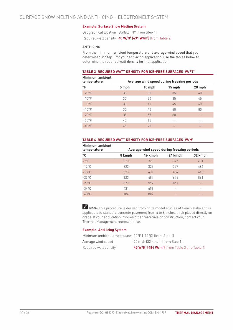

Surface Snow Melting and Anti-Icing
1 Determine design conditions
2 Select the heating cable
3 Determine the required watt density
4 Determine heating cable spacing
5 Determine the total area to be protected
9 Select the control system and power distribution
6 Determine heating cable length
7 Determine the electrical parameters
8 Select the connection kits and accessories
10 Complete the Bill of Materials
Step Determine heating cable spacing
SURFACES
To determine your heating cable spacing you need to know your applicationsrsquos power output and required watt density
The power output from the ElectroMelt heating cable depends on the supply voltage used in the application Table 5 lists power output per linear foot of heating cable determined by the supply voltage Divide this figure by the required watt density that you determined in Step 3 You will get the required heating cable spacing in feet or meters as applicable Multiply this figure by 12 inches or by 100 centimeters to determine your heating cable spacing
TAbLE 5 HEATING CAbLE SPACING IN CONCRETESupply voltage Catalog number Power output Wft (Wm)208 V EM2-XR 30 (98)240 V EM2-XR 32 (105)277 V EM2-XR 34 (112)
To determine cable spacing required for surface snow melting and anti-icing
Heating cable spacing (in) = (Wft power output of cable per Table 5) x 12 in
Wft2 requirement from Step 3
Heating cable spacing (cm) = (Wm power output of cable per Table 5) x 100 cm
Wm2 requirement from Step 3
Round answer to nearest whole number of inches or centimeters
Example Surface Snow Melting SystemSupply voltage 277 V (from Step 1)Heating cable EM2-XR (from Step 2)Power output 34 Wft (112 Wm2) (from Table 5)Spacing (34 Wft x 12 in) 40 Wft2 = 102 in Rounded to 10 in (112 Wm x 100 cm) 431 Wm2 = 26 cm
Example Anti-Icing System Supply voltage 277 V (from Step 1)Heating cable EM2-XR (from Step 2)Power output 34 Wft (from Table 5)Spacing (34 Wft x 12 in) 45 Wft2 = 91 in Rounded to 9 in (112 Wm x 100 cm) 484 wm2 = 231 cm Rounded to 23 cm
11 34THERMAL MANAGEMENT Raychem-DG-H53393-ElectroMeltSnowMeltingCOM-EN-1707
STAIRSHeat loss in stairs occurs from the two exposed surfaces the top of the stair and its side Watt density requirements are therefore greater for snow melting and anti-icing Rather than calculating heating cable spacing in the stair refer to Table 6 and determine the number of runs of heating cable per stair based on the depth of the stair Space the heating cable evenly across the depth of the stair with one run 2 in (5 cm) from the front or nose of the stair This method will provide sufficient watt density for both snow melting and anti-icing
TAbLE 6 HEATING CAbLE RUNS PER STAIRStair depth Number of cable runs per stairLess than 105 in (27 cm) 2105ndash12 in (27ndash30 cm) 3
For landings in the stairway use cable spacing as calculated for surfaces As with stairs a run of heating cable must be placed 2 in (5 cm) from the exposed edge of the landing leading to the stairs
Anticipate and design for the addition of railings or other follow on construction that will require cutting or drilling into the concrete as damage to installed heating cable may occur Allow for at least 4 inches clearance between the heating cable and any planned cuts or holes
Example Surface Snow Melting and Anti-Icing SystemDepth of stair 12 in (30 cm) (from Step 1)Number of cable runs per stair 3 runsSpacing Equally spaced across the width of the stair with one run 2 in (5 cm) from the front edge
6 in
Riser height (15 cm)
12 inStair
depth
(30 cm)
5 ft (15 m)
Width
3 ftLanding depth
(09 m)
Junctionbox
Fig 5 Typical heating cable layout for concrete stairs
SURFACE SNOW MELTING AND ANTI-ICING ndash ELECTROMELT SYSTEM
12 34 THERMAL MANAGEMENTRaychem-DG-H53393-ElectroMeltSnowMeltingCOM-EN-1707
Surface Snow Melting and Anti-Icing
1 Determine design conditions
2 Select the heating cable
3 Determine the required watt density
4 Determine heating cable spacing
5 Determine the total area to be protected
9 Select the control system and power distribution
6 Determine heating cable length
7 Determine the electrical parameters
8 Select the connection kits and accessories
10 Complete the Bill of Materials
Step Determine the total area to be protected
SURFACES
To determine the total amount of heating cable you need to determine the surface area you will be protecting from snow and ice accumulation If assistance is required in designing for irregular shaped areas please contact your Thermal Management representative
Example Surface Snow Melting SystemTotal area of concrete slab 80 ft x 50 ft = 4000 ft2 (244 m x 152 m = 3708 rounded to = 371 m2)
Example Anti-Icing SystemTotal area of concrete slab 80 ft x 50 ft = 4000 ft2 (244 m x 152 m = 3708 rounded to = 371 m2)
WHEEL TRACKS
To reduce power consumption for concrete driveways it may be sufficient to provide snow melting for only the wheel tracks
Design wheel track applications with the same spacing used for concrete slabs Heating cable should run to the edge of each side of the wheel track and be laid in a serpentine pattern along the length of the wheel track
Cable in 6 in minimum(15 cm) from edge unless curbs used
66 (2 m) typ
Structurally sound well-drained base designed tohandle expected load andenvironmental conditions
Fig 6 Wheel track example
STAIRS
Surface area of the stairs is not required to determine heating cable required
13 34THERMAL MANAGEMENT Raychem-DG-H53393-ElectroMeltSnowMeltingCOM-EN-1707
Surface Snow Melting and Anti-Icing
1 Determine design conditions
2 Select the heating cable
3 Determine the required watt density
4 Determine heating cable spacing
5 Determine the total area to be protected
9 Select the control system and power distribution
6 Determine heating cable length
7 Determine the electrical parameters
8 Select the connection kits and accessories
10 Complete the Bill of Materials
Step Determine heating cable length
SURFACESCalculate the heating cable length by dividing the total heated area by the heating cable spacing calculated in the previous steps In Step 8 you will need to add additional heating cable for connection kits and end terminations which will then give you the total heating cable length Calculate the heating cable length for the surface as follows
Heating cable length = Heated area (ft2) x 12
Heating cable spacing (in)
Heated area (m2) x 100
Heating cable spacing (cm)
Example Surface Snow Melting System for Concrete SlabTotal area of concrete slab 4000 ft2 (371 m2) (from Step 5)Cable spacing 10 in (26 cm) (from Step 4) (4000 ft2 x 12 in) 10 in spacing = 4800 ft (371 m2 x 100 cm) 26 cm spacing = 1427 mHeating cable length 4800 ft (1427 m)
Example Anti-Icing System for Concrete SlabTotal area of concrete slab 4000 ft2 (371 m2) (from Step 5)Cable spacing 9 in (23 cm) (from Step 4) (4000 ft2 x 12 in) 9 in spacing = 5333 ft (371 m2 x 100 cm) 23 cm spacing = 1613 mHeating cable length 5333 ft (1613 m)
SURFACE SNOW MELTING AND ANTI-ICING ndash ELECTROMELT SYSTEM
14 34 THERMAL MANAGEMENTRaychem-DG-H53393-ElectroMeltSnowMeltingCOM-EN-1707
STAIRS
6 in
Riser height(15 cm)
12 inStair depth
(30 cm)
5 ft (15 m)
Width
3 ftLanding depth
(09 m)
Junctionbox
Fig 7 Concrete stair example
Use the formula below to determine the length of cable required for stairs Stair area is not needed for the cable length calculation Two or three runs of heating cable will be installed per stair as determined in Step 3 For landing areas use the equation for surfaces
Length of cable for stair (ft) (m)
No of stairs = x [(No runs per stair x width of stair) + (2 x riser height)]
Example Surface Snow Melting and Anti-Icing System for StairsNumber of stairs 10 stairs (from Step 1)Number of cable runs per stair 3 runsWidth of stair 5 ft (15 m) (from Step 1)Riser height 6 in (15 cm) convert to 05 ft (015 m) (from Step 1) 10 stairs x [(3 x 5 ft) + (2 x 05 ft)] = 160 ft 10 stairs x [(3 x 15 m) + (2 x 015 m)] = 48 mHeating cable length 160 ft (48 m)
For applications where the landing area is very large or where an expansion joint exists between the stairs and landing consider the stairs and landing as two separate areas In these cases determine the length of cable required for the stairs as shown earlier in this section and select the cable for the landing as shown for ramps slabs driveways sidewalks platform scales
15 34THERMAL MANAGEMENT Raychem-DG-H53393-ElectroMeltSnowMeltingCOM-EN-1707
Surface Snow Melting and Anti-Icing
1 Determine design conditions
2 Select the heating cable
3 Determine the required watt density
4 Determine heating cable spacing
5 Determine the total area to be protected
9 Select the control system and power distribution
6 Determine heating cable length
7 Determine the electrical parameters
8 Select the connection kits and accessories
10 Complete the Bill of Materials
Step Determine the electrical parameters
This section will help you determine the electrical parameters for an ElectroMelt system including circuit breaker sizing and maximum circuit length Total required heating cable length divided by maximum circuit length will determine the number of circuits required for your snow melting solution
DETERMINE MAXIMUM CIRCUIT LENGTH
To determine maximum circuit length it is important to establish a minimum startup temperature for the system The following tables provide maximum circuit lengths based on minimum startup temperature circuit breaker rating and supply voltage Colder temperature startup requires shorter maximum circuit lengths The use of an automatic system which energizes the system above 20degF (ndash7degC) ensures that you can use maximum circuit lengths Manual control systems may require you to use shorter circuit lengths to compensate for startup below 20degF (ndash7degC)
A 30-mA ground-fault protection device (GFPD) must be used to provide protection from arcing or fire and to comply with warranty requirements agency certifications and national electrical codes If the heating cable is improperly installed or physically damaged sustained arcing or fire could result If arcing does occur the fault current may be too low to trip conventional circuit breakers
TAbLE 7 MAXIMUM CIRCUIT LENGTH FOR STARTUP AT 20degF (ndash7degC) IN FEET (METERS) USING AN AUTOMATIC SNOW CONTROL SYSTEM
Circuit breaker (A)
Heating cable supply voltage 208 V 240 V 277 V
15 80 (24) 85 (26) 100 (31)20 105 (32) 115 (35) 130 (40)30 160 (49) 170 (52) 195 (59)40 210 (64) 230 (70) 260 (79)50 265 (81) 285 (87) 325 (99)
TAbLE 8 MAXIMUM CIRCUIT LENGTH FOR STARTUP AT 0degF (ndash18degC) IN FEET (METERS) USING A MANUAL CONTROL SYSTEM
Circuit breaker (A)
Heating cable supply voltage 208 V 240 V 277 V
15 75 (23) 80 (24) 90 (27)20 100 (31) 110 (34) 120 (37)30 145 (44) 160 (49) 180 (55)40 200 (61) 210 (64) 240 (73)50 245 (75) 265 (81) 300 (91)
WARNING To minimize the danger of fire from sustained electrical arcing if the heating cable is damaged or improperly installed and to comply with the requirements of Thermal Management agency certifications and national electrical codes ground-fault equipment protection must be used on each heating cable branch circuit Arcing may not be stopped by conventional circuit protection
Example Surface Snow Melting and Anti-Icing System with Automatic Snow ControlStartup temperature 20degF (ndash7degC) (from Step 1)Circuit breakers 50 ASupply voltage 277 V (from Step 1)Maximum circuit length 325 ft (99 m) (from Table 7)
SURFACE SNOW MELTING AND ANTI-ICING ndash ELECTROMELT SYSTEM
16 34 THERMAL MANAGEMENTRaychem-DG-H53393-ElectroMeltSnowMeltingCOM-EN-1707
DETERMINE NUMbER OF CIRCUITS Use the following formula to determine number of circuits for the system
Number of circuits = Heating cable length required
Maximum heating cable circuit length
Example Surface Snow MeltingSurfacesTotal heating cable length 4800 ft (1427 m) (from Step 6)Maximum circuit length 325 ft (99 m) (from above)Number of circuits 4800 325 = 148 rounded to 15 circuitsStairsTotal heating cable length 160 ft (48 m) (from Step 6)Maximum circuit length 325 ft (99 m) (from above)Number of circuits 160 325 = 05 rounded to 1 circuit
Example Anti-Icing SystemSurfacesTotal heating cable length 5333 ft (1613 m) (from Step 6)Maximum circuit length 325 ft (99 m)Number of circuits 5333 325 = 164 rounded to 17 circuitsStairsTotal heating cable length 160 ft (48 m) (from Step 6)Maximum circuit length 325 ft (99 m) (from above)Number of circuits 160 325 = 05 rounded to 1 circuit
DETERMINE TRANSFORMER LOADThe total transformer load is the sum of load on all the circuit breakers in the system
Calculate the Circuit breaker Load (CbL) as
CBL (kW) = Circuit breaker rating (A) x 08 x Supply voltage
1000
Calculate the Total Transformer Load as follows
If the CBL is equal on all circuit breakers calculate the Total Transformer Load as
Total Transformer Load (kW) = CBL x Number of circuits
If the CBL is not equal on all circuit breakers calculate the Total Transformer Load as
Total Transformer Load (kW) = CBL1 + CBL2 + CBL3+ CBLN
17 34THERMAL MANAGEMENT Raychem-DG-H53393-ElectroMeltSnowMeltingCOM-EN-1707
Example Surface Snow MeltingCircuit breaker load (50 A x 08 x 277 V) 1000 = 111 kWTransformer Load 111 kW x 16 circuits = 1776 kW rounded to 178 kW 178 kW
Example Anti-Icing SystemCircuit breaker load (50 A x 08 x 277 V) 1000 = 111 kWTransformer load 111 kW x 18 circuits = 1998 kW rounded to 200 kW 200 kW
Surface Snow Melting and Anti-Icing
1 Determine design conditions
2 Select the heating cable
3 Determine the required watt density
4 Determine heating cable spacing
5 Determine the total area to be protected
9 Select the control system and power distribution
6 Determine heating cable length
7 Determine the electrical parameters
8 Select the connection kits and accessories
10 Complete the Bill of Materials
Step Select the connection kits and accessories
Thermal Management provides all the connection kits and accessories necessary to satisfy code approval agency and warranty requirements for the ElectroMelt system Additional heating cable will be required for connection kits and end terminations Adding the additional heating cable allowances needed with the heating cable length required for the layout will give you the total heating cable length required
Prepare a drawing of your system showing distinct circuits layout of cables connection kits expansion joints drains heated pathways for meltwater power connections junction boxes and sensors Determine length of cable from slab for power connection for all circuits If possible avoid crossing expansion crack control or other pavement joints Use the EMK-XEJ expansion joint kit to protect the heating cable if crossing is unavoidable
Junction boxes must be mounted above grade to prevent water entry Use an EMK-XJB or equivalent UL Listed or CSA Certified weatherproof junction box Protect heating cable from slab to junction box inside individual 1-inch rigid metal conduits Do not penetrate floors or walls with conduit nor insulate the conduit
SURFACE SNOW MELTING AND ANTI-ICING ndash ELECTROMELT SYSTEM
18 34 THERMAL MANAGEMENTRaychem-DG-H53393-ElectroMeltSnowMeltingCOM-EN-1707
TAbLE 9 CONNECTION KITS AND ACCESSORIESCatalog number Description
Standard packaging Usage
Heating cable allowance 1
Connection Kits
Power connection EMK-XP
End seal EMK-XP
EMK-XP Power connection and end seal kit
1 1 per circuit 3 ft (1 m) for connection plus conduit length for power connection and conduit length for end seal
EMK-XS Splice kit 1 As required 1 ft (30 cm)
Accessories
EMK-XJR Jacket repair kit 1 As required ndash
EMK-CT Nylon cable ties 100pack 1 per foot of cable used
ndash
EMK-XT Crimping tool 1 ndash ndash
SMCS Snow melt caution sign Dimensions 6 x 4 in (150 x 100 mm)
1 1 minimum per system
ndash
EMK-XEJ Expansion joint kit 1 1 per expansion joint crossing
1 12 ft (45 cm)
EMK-XJB Junction boxDimensions 15 12 x 11 34 x 7 58 in (394 x 299 x 194 mm)
1 1ndash2 ft (30ndash60 cm) for each end in the junction box
Maximum of two circuits per EMK-XJB
1 Allow extra heating cable for ease of component installation
19 34THERMAL MANAGEMENT Raychem-DG-H53393-ElectroMeltSnowMeltingCOM-EN-1707
Example Surface Snow Melting SystemNumber of circuits 15 for concrete slab + 1 for stairs = 16Power connection kits 16 power connection kitsConduit length (from slab to junction box) Power connection 15 ft (45 m) End seal 15 ft (45 m) (15 ft + 15 ft) x 16 circuits = 480 ft (45 m + 45 m) x 16 circuits = 144 mHeating cable allowance for each power connection 3 ft x 16 circuits = 48 ft 1 m x 16 circuits = 16 mTotal heating cable length required 528 ft (160 m)
Example Anti-Icing SystemNumber of circuits 17 for concrete slab + 1 for stairs = 18Power connection kits 18 power connection kitsConduit length (from slab to junction box) Power connection 15 ft (45 m) End seal 15 ft (45 m) (15 ft + 15 ft) x 18 circuits = 540 ft (45 m + 45 m) x 18 circuits = 162 mHeating cable allowance for each power connection 3 ft x 18 circuits = 54 ft 1 m x 18 circuits = 18 mTotal heating cable length required 594 ft (180 m)
SURFACE SNOW MELTING AND ANTI-ICING ndash ELECTROMELT SYSTEM
20 34 THERMAL MANAGEMENTRaychem-DG-H53393-ElectroMeltSnowMeltingCOM-EN-1707
Surface Snow Melting and Anti-Icing
1 Determine design conditions
2 Select the heating cable
3 Determine the required watt density
4 Determine heating cable spacing
5 Determine the total area to be protected
9 Select the control system and power distribution
6 Determine heating cable length
7 Determine the electrical parameters
8 Select the connection kits and accessories
10 Complete the Bill of Materials
Step Select the control system and power distribution
CONTROL SYSTEMS
Select a control system from the following three options but keep in mind that an automatic snow controller offers the highest system efficiency and the lowest operating cost bull Manual onoff controlbull Slab sensing thermostatbull Automatic snow melting controller
If the current rating of the control means is exceeded all three methods will require contactors sized to carry the load Each method offers a tradeoff balancing initial cost versus energy efficiency and ability to provide effective snow melting If the system is not energized when required snow will accumulate If the system is energized when it is not needed there will be unnecessary power consumption Choose the control method that best meets the project performance requirements For additional information refer to the ldquoTypical Control Diagramsrdquo Table 7 or contact your Thermal Management representative for details
Manual OnOff ControlA manually controlled system is operated by a switch that controls the system power contactor This method requires constant supervision to work effectively A manual system can be controlled by a building management system
Slab Sensing ThermostatA slab sensing thermostat can be used to energize the system whenever the slab temperature is below freezing but is not energy efficient when used as the sole means of control The slab sensing thermostat is recommended for all snow melting applications even when an automatic snow controller is used and is required for all asphalt and paver installations (for asphalt it prevents surface damage due to overheating)
Automatic Snow Melting ControllerWith an automatic snow controller the snow melting system is automatically energized when both precipitation and low temperature are detected When precipitation stops or the ambient temperature rises above freezing the system is de-energized In addition a slab sensor de-energizes the system after the slab reaches the slab sensing set point even if freezing precipitation is still present Using an automatic snow controller with a slab sensor offers the most energy-efficient control solution
For areas where a large number of circuits are required the Raychem ACS-30 can be used The Surface Snow Melting control mode in the ACS-30 includes an External Device control option This option allows a SnowMoisture sensing controller (from Table 10) to be integrated into the ACS-30 system Note that sensors (snow or gutter) cannot be directly connected to the ACS-30 system Refer to the ACS-30 Programming Guide (H58692) for more information on system setup
21 34THERMAL MANAGEMENT Raychem-DG-H53393-ElectroMeltSnowMeltingCOM-EN-1707
CIT-1snow sensor
To power supply or incorporate the ETI snow melting control system into a power distribution panel
APS-4C (shown) with SC-40C satelllitecontactor or APS-3C snow controller
OptionalSC-40Csatellite contactor
To additionalSC-40C satellitecontactors
To heating cable(s)
To heating cable(s)
Optional RCU-3 or RCU-4 remote control unit
To power supply
SIT-6E pavement mounted sensor
Environmental Technology Inc (ETI) of South Bend Indiana offers a complete line of automatic controllers for snow melting applications
Fig 8 Automatic snow melting control system
TAbLE 10 CONTROL SYSTEMS Catalog number Description
Slab Sensing ThermostatECW-GF Electronic ambient sensing controller with 30-mA ground-fault protection The control-
ler can be programmed to maintain temperatures up to 200degF (93degC) at voltages from 100 to 277 V and can switch current up to 30 Amperes The ECW-GF is complete with a 25-ft (76-m) temperature sensor and is housed in a Type 4X rated enclosure The controller features an ACDC dry alarm contact relay
An optional ground-fault display panel (ECW-GF-DP) that can be added to provide ground-fault or alarm indication in applications where the controller is mounted in inaccessible locations
ECW-GF-DP An optional remote display panel (ECW-GF-DP) can be added to provide ground-fault or alarm indication in applications where the controller is mounted in inaccessible locations
HEATER CYCLE
PD Pro Automatic snow and ice melting controller for pavement sidewalks loading docks roofs gutters and downspouts in commercial and residential environments The PD Pro interfaces with up to two sensors (any combination of CIT-1 GIT-1 or SIT-6E) to meet site requirements The PD Pro is housed in an environmentally-sheltered Type 4X enclosure and weighs only 3 pounds
GF Pro Automatic snow and ice melting controller for pavement sidewalks loading docks roofs gutters and downspouts in commercial and residential environments The GF Pro interfaces with up to two sensors (any combination of CIT-1 GIT-1 or SIT-6E) to meet site requirements The GF Pro is housed in an environmentally-sheltered Type 4X enclosure and weighs only 3 pounds
Features a built-in 30 mA self-testing Ground-Fault Equipment Protection (GFEP) capability digitally filtered to minimize false tripping A ground-fault alarm must be manually reset using the TestReset switch before heater operation can continue
SURFACE SNOW MELTING AND ANTI-ICING ndash ELECTROMELT SYSTEM
22 34 THERMAL MANAGEMENTRaychem-DG-H53393-ElectroMeltSnowMeltingCOM-EN-1707
TAbLE 10 CONTROL SYSTEMS Catalog number Description
Automatic Snow Melting ControllersAPS-3C Automatic snow melting controller housed in a Type 3R enclosure provides effective
economical automatic control of all snow melting applications Features include 120 V or 208ndash240 V models 24-A DPDT output relay and an adjustable hold-on timer
Enclosure dimensions 11-12 in x 9-18 in x 6-916 in (292 mm x 232 mm x 167 mm)
APS-4C Automatic snow melting controller housed in a Type 3R enclosure provides effective economical automatic control of all snow melting applications The APS-4C can oper-ate with any number of SC-40C satellite contactors for larger loads Features include 277 V single-phase or 208ndash240 277480 and 600 V three-phase models built-in 3-pole contactor integral 30 mA ground-fault circuit interrupter and an adjustable hold-on timer
Enclosure dimensions 11-12 in x 9-18 in x 6-916 in (292 mm x 232 mm x 167 mm)
SC-40C Satellite contactor power control peripheral for an APS-4C snow melting control-ler housed in a Type 3R enclosure Features include 277 V single-phase or 208ndash240 277480 and 600 V three-phase models built-in 3-pole contactor and integral 30 mA ground-fault circuit interrupter
Enclosure dimensions 11-12 in x 9-18 in x 6 in (292 mm x 232 mm x 152 mm)
Snow Melting and Gutter De-Icing Sensors and Accessories
CIT-1 Overhead snow sensor that detects precipitation or blowing snow at ambient temper-atures below 38degF (33degC) For use with either an APS-3C or APS-4C automatic snow melting controller
SIT-6E Pavement-mounted sensor signals for the heating cable to turn on when the pavement temperature falls below 38degF (33degC) and precipitation in any form is present Microcontroller technology effectively eliminates ice bridging while ensuring accurate temperature measurement For use with either an APS-3C or APS-4C automatic snow melting controller
RCU-3 The RCUndash3 provides control and status display to the APSndash3C controller from a remote location It has a 2 4 6 or 8 hour CYCLE TIME adjustment independent of APS-3C setting
RCU-4 The RCUndash4 provides control and status display to the APSndash4C controller and SC-40C Satellite Contactor from a remote location It has a 2 4 6 or 8 hour CYCLE TIME adjustment independent of the APS-4C or SC-40C setting
23 34THERMAL MANAGEMENT Raychem-DG-H53393-ElectroMeltSnowMeltingCOM-EN-1707
TAbLE 10 CONTROL SYSTEMS Catalog number Description
Electronic Controllers
ACS-UIT2ACS-PCM2-5
The Raychem ACS-30 Advanced Commercial Control System is a multipoint electronic control and monitoring system for heat-tracing used in various commercial applications such as pipe freeze protection roof and gutter de-icing surface snow melting hot water temperature maintenance and floor heating The Raychem ACS-30 system can control up to 260 circuits with multiple networked ACS-PCM2-5 panels with a single ACS-UIT2 user interface terminal The ACS-PCM2-5 panel can directly control up to 5 individual heat-tracing circuits using electromechanical relays rated at 30 A up to 277 V
By FieldServer TechnologieswwwProtoCessorcom
PROTOCESSORSERIAL ETHERNET
PROTONODE
FRAME GND- PWR+PWR
RS 485+RS 485 -RS 485 GND
S3S2S1S0B3B2B1B0
A7A6A5A4A3A2A1A0
ProtoNode-RER The Raychem ProtoNode is an external high performance multi-protocol gateway for customers needing protocol translation between Building Management Systems (BMS) and the Raychem ACS-30 or C910-485 controllers
The ProtoNode-RER is for BACnetreg or Metasysreg N2 systems
RTD-200 RTD10CSRTD50CS
Stainless steel jacketed three-wire RTD (Resistance Temperature Detector) used with Raychem C910-485 and ACS-30 controllers
RTD-200 3-in (76 mm) temperature sensor with a 6-ft (18 m) lead wire and 12-in NPT bushing
RTD10CS temperature sensor with a 10-ft (3 m) flexible armor 18-in (457 mm) lead wire and 12-inch NPT bushing
RTD50CS temperature sensor with a 50-ft (3 m) flexible armor 18-in (457 mm) lead wire and 12-in NPT bushing
POWER DISTRIbUTION
Single Circuit ControlHeating cable circuits that do not exceed the current rating of the selected temperature control can be switched directly (see Fig 9)
Group ControlIf the current draw exceeds the switch rating or if the controller will activate more than one circuit or group control an external contactor must be used (see Fig 9)
Large systems with many circuits should use an SMPG power distribution panel The SMPG is a dedicated power-distribution control ground-fault protection monitoring and alarm panel for surface snow melting and anti-icing applications This enclosure contains an assembled circuit-breaker panelboard Panels are equipped with ground-fault circuit breakers with or without alarm contacts The group control package allows the system to operate automatically in conjunction with an ambient-sensing thermostat individual electronic or duty cycle controller
SURFACE SNOW MELTING AND ANTI-ICING ndash ELECTROMELT SYSTEM
24 34 THERMAL MANAGEMENTRaychem-DG-H53393-ElectroMeltSnowMeltingCOM-EN-1707
Single circuit control Group control
Temperaturecontroller
1-poleGFEP breaker
1N
G
Heatingcable
oslashoslash supply
C
Temperaturecontroller
Contactor
1-poleGFEP breaker
N
G (Typ 3)
oslash2
oslash1
oslash3
3-phase 4-wiresupply (WYE)
3-pole mainbreaker
oslash
oslash 1 supply
N
Heating cable sheath braid or ground
Heating cable sheath braid or ground
Fig 9 Single circuit and group control
Exterior View Interior View
NP
NP
NP
NP
G
NP
NP
G
NP
R
NP
Nameplate
Mounting brackets
Heater thermostat(3R only)
Power on lightHTC energized light
CB tripped alarm
Heater (3R only)
Door lock handle
SnowIcemelt controller
Ground bar
Panelboardlugs
Control wiring
Heater cycle atimed control
EUR - 5A
Main breaker(optional)
Heat tracecontactor
Branch breakers(2 pole)
Panelboard
Fig 10 SMPG1 power distribution panel
N
Three-pole main contactor
FuseMain circuit breaker (optional)
Incomingpower
GND
24 V
One-pole with 30-mAground-fault trip (277 V)
Remote annunciation alarm(circuit breaker
with alarm type 3)
GIT-1
CIT-1
SIT-6E
Braid
Aerialsnow sensor
Gutterice sensor
Slabtemperature sensor
Pavement-mountedsensor
Single Oslashconnection
SNOWICE
SUPPLY
EUR-5A SNOW SWITCHAUTOMATIC SNOWICE MELTING CONTROL PANEL
HEATER
HEATERCYCLE
HOURS
0
45degF
50degF
55degF
60degF65degF
70degF
75degF
80degF
85degF
2
4 6
8
10
TEMPERATURE
Control transformer
Fig 11 Typical wiring diagram of group control with SMPG1
25 34THERMAL MANAGEMENT Raychem-DG-H53393-ElectroMeltSnowMeltingCOM-EN-1707
TAbLE 11 POWER DISTRIbUTIONCatalog number Description
Power Distribution and Control Panels
NP
NP
NP
NP
NP
NP
NP
SMPG1 Single-phase power distribution panel that includes ground-fault protection monitor-ing and control for snow melting systems Single-phase voltages include 208 and 277 V
If standard configurations do not meet your needs custom SMPG panels are available and processed under the catalog number SMPG-GENERAL part number P000000763 Please contact your Thermal Management representative for a custom SMPG panel quotation
Example Surface Snow Melting SystemThis system has 16 circuits and will require a specially designed control panel As many as eight SIT-6E sensors can be used in this configuration The amount depends upon designer preference
Example Anti-Icing SystemThis system has 18 circuits and will require a specially designed control panel As many as eight SIT-6E sensors can be used in this configuration The amount depends upon designer preference
SURFACE SNOW MELTING AND ANTI-ICING ndash ELECTROMELT SYSTEM
26 34 THERMAL MANAGEMENTRaychem-DG-H53393-ElectroMeltSnowMeltingCOM-EN-1707
Surface Snow Melting amp Anti-Icing
1 Determine design conditions
2 Select the heating cable
3 Determine the required watt density
4 Determine heating cable spacing
5 Determine the total area to be protected
9 Select the control system and power distribution
6 Determine heating cable length
7 Determine the electrical parameters
8 Select the connection kits and accessories
10 Complete the Bill of Materials
Step 0 Complete the bill of Materials
If you used the Design Worksheet to document all your design parameters you should have all the details you need to complete the Bill of Materials
27 34THERMAL MANAGEMENT Raychem-DG-H53393-ElectroMeltSnowMeltingCOM-EN-1707
ELECTROMELT SYSTEM SURFACE SNOW MELTING AND ANTI-ICING DESIGN WORKSHEET
Step Determine design conditions
Application Size and layoutSupply voltage Phase Control method
Surface snow melting Geographical location _____________________
Anti-icing Minimum ambient temperature _____________________ Average wind speed during freezing periods (mphkmph) ____________________
Paving material Concrete pavement In concrete under paving stones
Slab surface (ftm) __________________Ramp surface (ftm) _________________ Stairs Number of stairs ______________ Width of stair (ftm) ______________ Riser height (incm) ______________ Depth of stair (incm) ______________ Landing dimensions (ftm) ______________Wheel tracks Track length (ftm) ____________
208 V
240 V
277 V
Single-phase Manual onoff control Slab-sensing thermostat Automatic snow melting
controller
Example9 Surface snow melting9 buffalo NY9 Concrete slab
Slab surface 80 ft x 50 ftStairs Number of stairs 10 Width of stair 5 ft Riser height 6 in Depth of stair 12 in
9 277 V 9 Single-phase 9 Automatic snow melting controller
Step Select the heating cableSee Table 1 EM2-XR
Example9 EM2-XR
Step Determine the required watt densitySurface snow melting
See Table 2Anti-icing
See Table 3 and Table 4
Geographical location _________________________Required watt density (Wft2)(Wm2) ___________________________
Minimum ambient temperature (degFdegC) _______
Average wind speed during freezing periods (mphkmph) ______
Required watt density (Wft2)(Wm2) _______
ExampleGeographical location buffalo NYRequired watt density 40 Wft2
SURFACE SNOW MELTING AND ANTI-ICING ndash ELECTROMELT SYSTEM
28 34 THERMAL MANAGEMENTRaychem-DG-H53393-ElectroMeltSnowMeltingCOM-EN-1707
Step Determine heating cable spacingSee Table 5
34 Wft
12 in 3
3Equally spaced across the width of the stairwith one run 2 in from the front edge
40 Wft2 10 in
Power output (Wft) Watt density (Wft2)
x( )Heating cable spacing (in)
12 inftPower output (Wft)
Stairs
Surfaces
Surfaces
Calculate the heating cable needed for stairs and landing
Determine the number of cable runs needed
Depth of stair lt105 in (27 cm) 2 cable runs
Depth of stair 105ndash12 in (27ndash30 cm) 3 cable runs
Cable runs needed
Concrete stair depth (incm) Number of cable runs Spacing
StairsCalculate the heating cable needed for stairs and landing
Determine the number of cable runs needed
Depth of stair lt105 in (27 cm) 2 cable runs
Depth of stair 105ndash12 in (27ndash30 cm) 3 cable runs
Cable runs needed
x( )12 inft
=Watt density (Wft2)
Example
Note Round result to the nearest whole number of inches or centimeters
Heating cable spacing (incm)=
Concrete stair depth (incm) Number of cable runs Spacing
Note Round result to the nearest whole number of inches or centimeters
Step Determine the total area to be protected
x80 ft 4000 ft2
Length
50 ft
Width
xSurface area to be protected (ft2m2)Length (ftm) Width (ftm)
=
Example
Surfaces
Surface area to be protected (ft)=
29 34THERMAL MANAGEMENT Raychem-DG-H53393-ElectroMeltSnowMeltingCOM-EN-1707
Step Determine the heating cable length
xHeating cable length for surface
4000 ft2
12 in10 in 4800
Total concrete slab area
Calculate the heating cable for stairs and landing
=Heating cable spacing
x x x =
=
=
=
=
+( () )10
No of stairs
32
No of runs per stair
5 ft
Width of stair
05 ft
Riser height
160 ft
4960 ft
Heating cable length for stairs[ ]
Note Additional heating cable for connection kits and end terminations is calculated in Step 8
Calculate the heating cable for stairs and landing
Surfaces
Surfaces
x x x+( () )No of stairs
2No of runs per stair Width of stair (ftm) Riser height (ftm) Heating cable length for stairs (ftm)
[ ]
Note Additional heating cable for connection kits and end terminations is calculated in Step 8
Example
xHeating cable length for surface (ftm)
12 inTotal concrete slab area (ft2m2)
Heating cable spacing (incm)
Calculate heating cable needed for wheel tracks
x 2 x 4 runsWheel track to be protected (ftm)Length (ftm)
Total heating cable length required (ftm)
Total heating cable length required
SURFACE SNOW MELTING AND ANTI-ICING ndash ELECTROMELT SYSTEM
30 34 THERMAL MANAGEMENTRaychem-DG-H53393-ElectroMeltSnowMeltingCOM-EN-1707
Step Determine the electrical parametersSee Table 7 and Table 8
Number of circuits
4800 ft 325 ft 148 rounded to 15
Heating cable length required for surface =
Maximum heating cable circuit length
Determine number of circults Surfaces
Number of circuitsHeating cable length required for surface (ftm) =
Maximum heating cable circuit length (ftm)
Determine number of circults
Circuit breaker load (kW)08 1000
Circuit breaker rating (Amps )x x ( ) =
Supply voltage
Determine total transformer load
Calculate the total transformer load as follows
Calculate circuit breaker load (CBL)
If the CBL is equal on all circuits calculate the transformer load as
If the CBL is NOT equal on all circuits calculate the transformer load as
Total transformer load (kW)Circuit breaker load (kW)x =
Number of breakers
Total transformer load (kW)CBL1 + CBL2 + CBL3 + CBLN
=
Example
Number of circuits
160 ft 325 ft 05 rounded to 1
Heating cable length required for surface =
Maximum heating cable circuit length
Determine number of circults Stair
Circuit breaker load (kW)
50 A 277 V08 1000
111 kW
Circuit breaker ratingx x ( ) =
Supply voltage
Total transformer load (kW)
111 kW 16 1776 kW rounded to 178
Circuit breaker load (kW)x =
Determine transformer load
Number of breakers
31 34THERMAL MANAGEMENT Raychem-DG-H53393-ElectroMeltSnowMeltingCOM-EN-1707
Step Select the connection kit and accessoriesSee Table 9
Connection kits Description QuantityHeating cable allowance
T EMK-XP
T EMK-XS
Power connection and end seal kit
Splice kit____________
____________
__________________
__________________
Accessories Description Quantity
T EMK-XJR
T EMK-CT
T EMK-XT
T SMCS
T EMK-XEJ
T EMK-XJB
Jacket repair kit
Nylon cable ties
Crimping tool
Snow melt caution sign
Expansion joint kit
Junction box
____________
____________
____________
____________
____________
____________
__________________
__________________
+ =Total heating cable
length requiredTotal heating cable allowance for connection kitsTotal heating cable length
Total heating cableallowance for connection kits
15 1 16 16
15 ft 15 ft 480 ft
480 ft
16
3 ft 16 48 ft
48 ft
630 ft 63 693 ft
528 ft
Total no of circuitsNumber circuits for concrete slab+ =
Total no of power connection kits=
Circuit(s) for stairs+
Circuit(s) for expansion joints
Total conduit length (ftm)Power connection conduit length(slab to junction box) (ftm)
+ x( ) =End seal conduit length
(slab to junction box) (ftm)Total number of circuits
Total heating cable allowanceper power connection (ftm)
Cable allowance per circuit connection (ftm)
x =Total number of circuits
Total additionalheating cable (ftm)
Total conduit length (ftm)+ =
=Total heating cable with
connection kit allowance (ftm)
Total allowance per power connection kit (ftm)
Total heating cable length (ftm) Total heating cable allowance (ftm)+
Example
Total no of circuitsNumber circuits for concrete slab+ =
Total no of power connection kits=
Circuit(s) for stairs+
Circuit(s) for expansion joints
Total conduit lengthPower connection conduit length(slab to junction box)
+ x( ) =End seal conduit length
(slab to junction box)Total number of circuits
Total heating cable allowanceper power connection
Cable allowance per circuit connection
x =Total number of circuits
Total additional heating cableTotal conduit length+ =
=Total heating cable withconnection kit allowance
Total allowance per power connection kit
Total heating cable length Total heating cable allowance+
SURFACE SNOW MELTING AND ANTI-ICING ndash ELECTROMELT SYSTEM
32 34 THERMAL MANAGEMENTRaychem-DG-H53393-ElectroMeltSnowMeltingCOM-EN-1707
Step Select the control system and power distribution Control SystemsSee Table 10Thermostats controllers and accessories Description Quantity
T ECW-GF
T ECW-GF-DP
T PD Pro
T GF-Pro
T APS-3C
T APS-4C
T SC-40C
T CIT-1
T SIT-6E
T RCU-3
T RCU-4
T ACS-UIT2
T ACS-PCM2-5
T ProtoNode-RER
T RTD3CS
T RTD10CS
T RTD-200
T RTD50CS
Electronic thermostat with 25-ft sensor
Remote display panel for ECW-GF
Automatic snow and ice melting controllerAutomatic snow and ice melting controllerAutomatic snow and ice melting controllerAutomatic snow and ice melting controllerSatellite contactor
Overhead snow sensor
Pavement-mounted sensor
Remote control unit for APS-3C
Remote control unit for APS-4C
ACS-30 user interface terminal
ACS-30 power control panel
Multi-protocol gateway
Resistance temperature device for Raychem ACS-30
Resistance temperature device for Raychem ACS-30
Resistance temperature device for Raychem ACS-30
Resistance temperature device for Raychem ACS-30
____________
____________
____________
____________
____________
____________
____________
____________
____________
____________
____________
____________
____________
____________
____________
____________
____________
____________
Power DistributionSee Table 11
Power distribution and control panels Description Quantity
T SMPG1 Single-phase power distribution panel ____________
Step Complete the bill of Materials
Use the information recorded in this worksheet to complete the Bill of Materials
33 34THERMAL MANAGEMENT Raychem-DG-H53393-ElectroMeltSnowMeltingCOM-EN-1707
NORTH AMERICA Tel +18005456258Fax +18005275703Tel +16502161526Fax +16504747711thermalinfopentaircom
Pentair is owned by Pentair or its global affiliates All other trademarks are the property of their respective owners Pentair reserves the right to change specifications without prior notice
copy 2009-2017 Pentair
WWWPENTAIRTHERMALCOM
34 34THERMAL MANAGEMENT Raychem-DG-H53393-ElectroMeltSnowMeltingCOM-EN-1707
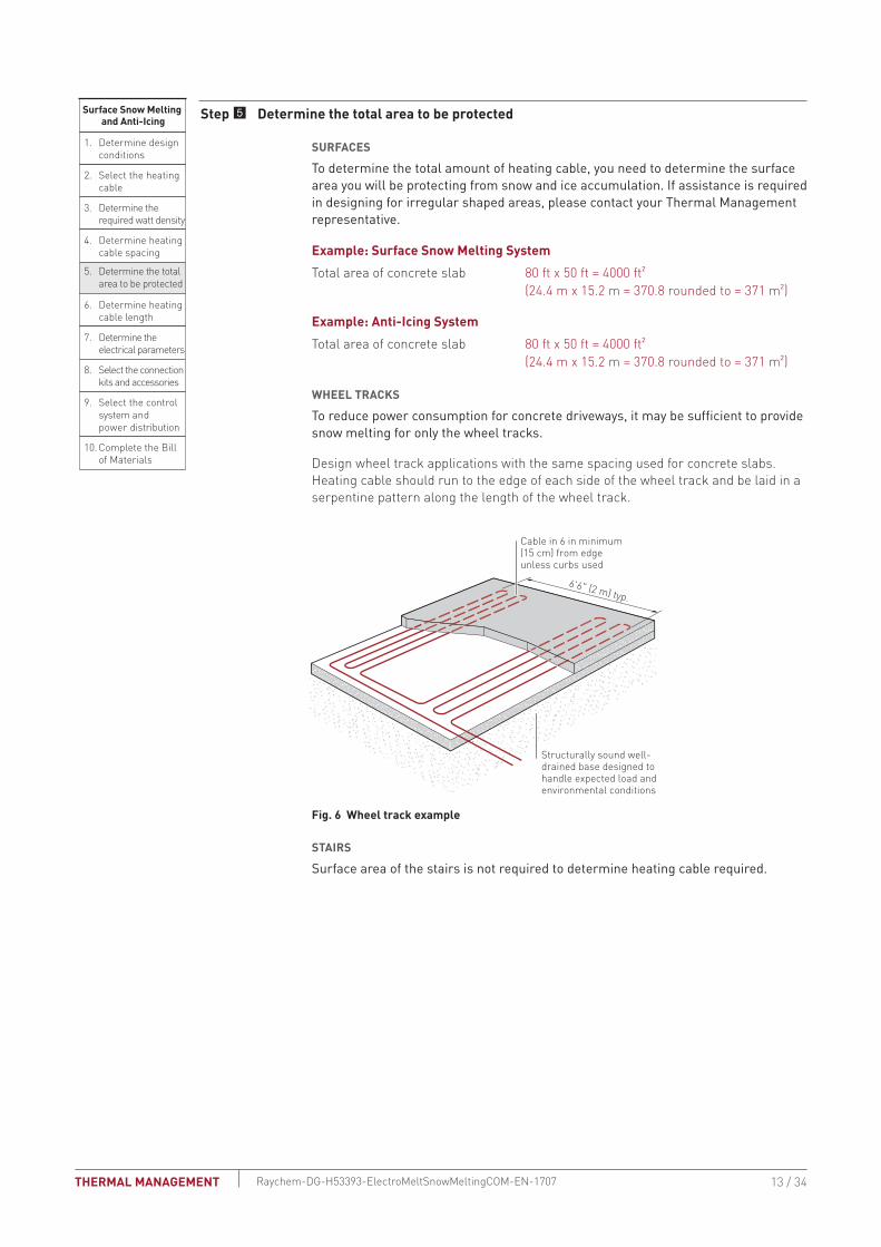
Surface Snow Melting and Anti-Icing
1 Determine design conditions
2 Select the heating cable
3 Determine the required watt density
4 Determine heating cable spacing
5 Determine the total area to be protected
9 Select the control system and power distribution
6 Determine heating cable length
7 Determine the electrical parameters
8 Select the connection kits and accessories
10 Complete the Bill of Materials
Step Determine the total area to be protected
SURFACES
To determine the total amount of heating cable you need to determine the surface area you will be protecting from snow and ice accumulation If assistance is required in designing for irregular shaped areas please contact your Thermal Management representative
Example Surface Snow Melting SystemTotal area of concrete slab 80 ft x 50 ft = 4000 ft2 (244 m x 152 m = 3708 rounded to = 371 m2)
Example Anti-Icing SystemTotal area of concrete slab 80 ft x 50 ft = 4000 ft2 (244 m x 152 m = 3708 rounded to = 371 m2)
WHEEL TRACKS
To reduce power consumption for concrete driveways it may be sufficient to provide snow melting for only the wheel tracks
Design wheel track applications with the same spacing used for concrete slabs Heating cable should run to the edge of each side of the wheel track and be laid in a serpentine pattern along the length of the wheel track
Cable in 6 in minimum(15 cm) from edge unless curbs used
66 (2 m) typ
Structurally sound well-drained base designed tohandle expected load andenvironmental conditions
Fig 6 Wheel track example
STAIRS
Surface area of the stairs is not required to determine heating cable required
13 34THERMAL MANAGEMENT Raychem-DG-H53393-ElectroMeltSnowMeltingCOM-EN-1707
Surface Snow Melting and Anti-Icing
1 Determine design conditions
2 Select the heating cable
3 Determine the required watt density
4 Determine heating cable spacing
5 Determine the total area to be protected
9 Select the control system and power distribution
6 Determine heating cable length
7 Determine the electrical parameters
8 Select the connection kits and accessories
10 Complete the Bill of Materials
Step Determine heating cable length
SURFACESCalculate the heating cable length by dividing the total heated area by the heating cable spacing calculated in the previous steps In Step 8 you will need to add additional heating cable for connection kits and end terminations which will then give you the total heating cable length Calculate the heating cable length for the surface as follows
Heating cable length = Heated area (ft2) x 12
Heating cable spacing (in)
Heated area (m2) x 100
Heating cable spacing (cm)
Example Surface Snow Melting System for Concrete SlabTotal area of concrete slab 4000 ft2 (371 m2) (from Step 5)Cable spacing 10 in (26 cm) (from Step 4) (4000 ft2 x 12 in) 10 in spacing = 4800 ft (371 m2 x 100 cm) 26 cm spacing = 1427 mHeating cable length 4800 ft (1427 m)
Example Anti-Icing System for Concrete SlabTotal area of concrete slab 4000 ft2 (371 m2) (from Step 5)Cable spacing 9 in (23 cm) (from Step 4) (4000 ft2 x 12 in) 9 in spacing = 5333 ft (371 m2 x 100 cm) 23 cm spacing = 1613 mHeating cable length 5333 ft (1613 m)
SURFACE SNOW MELTING AND ANTI-ICING ndash ELECTROMELT SYSTEM
14 34 THERMAL MANAGEMENTRaychem-DG-H53393-ElectroMeltSnowMeltingCOM-EN-1707
STAIRS
6 in
Riser height(15 cm)
12 inStair depth
(30 cm)
5 ft (15 m)
Width
3 ftLanding depth
(09 m)
Junctionbox
Fig 7 Concrete stair example
Use the formula below to determine the length of cable required for stairs Stair area is not needed for the cable length calculation Two or three runs of heating cable will be installed per stair as determined in Step 3 For landing areas use the equation for surfaces
Length of cable for stair (ft) (m)
No of stairs = x [(No runs per stair x width of stair) + (2 x riser height)]
Example Surface Snow Melting and Anti-Icing System for StairsNumber of stairs 10 stairs (from Step 1)Number of cable runs per stair 3 runsWidth of stair 5 ft (15 m) (from Step 1)Riser height 6 in (15 cm) convert to 05 ft (015 m) (from Step 1) 10 stairs x [(3 x 5 ft) + (2 x 05 ft)] = 160 ft 10 stairs x [(3 x 15 m) + (2 x 015 m)] = 48 mHeating cable length 160 ft (48 m)
For applications where the landing area is very large or where an expansion joint exists between the stairs and landing consider the stairs and landing as two separate areas In these cases determine the length of cable required for the stairs as shown earlier in this section and select the cable for the landing as shown for ramps slabs driveways sidewalks platform scales
15 34THERMAL MANAGEMENT Raychem-DG-H53393-ElectroMeltSnowMeltingCOM-EN-1707
Surface Snow Melting and Anti-Icing
1 Determine design conditions
2 Select the heating cable
3 Determine the required watt density
4 Determine heating cable spacing
5 Determine the total area to be protected
9 Select the control system and power distribution
6 Determine heating cable length
7 Determine the electrical parameters
8 Select the connection kits and accessories
10 Complete the Bill of Materials
Step Determine the electrical parameters
This section will help you determine the electrical parameters for an ElectroMelt system including circuit breaker sizing and maximum circuit length Total required heating cable length divided by maximum circuit length will determine the number of circuits required for your snow melting solution
DETERMINE MAXIMUM CIRCUIT LENGTH
To determine maximum circuit length it is important to establish a minimum startup temperature for the system The following tables provide maximum circuit lengths based on minimum startup temperature circuit breaker rating and supply voltage Colder temperature startup requires shorter maximum circuit lengths The use of an automatic system which energizes the system above 20degF (ndash7degC) ensures that you can use maximum circuit lengths Manual control systems may require you to use shorter circuit lengths to compensate for startup below 20degF (ndash7degC)
A 30-mA ground-fault protection device (GFPD) must be used to provide protection from arcing or fire and to comply with warranty requirements agency certifications and national electrical codes If the heating cable is improperly installed or physically damaged sustained arcing or fire could result If arcing does occur the fault current may be too low to trip conventional circuit breakers
TAbLE 7 MAXIMUM CIRCUIT LENGTH FOR STARTUP AT 20degF (ndash7degC) IN FEET (METERS) USING AN AUTOMATIC SNOW CONTROL SYSTEM
Circuit breaker (A)
Heating cable supply voltage 208 V 240 V 277 V
15 80 (24) 85 (26) 100 (31)20 105 (32) 115 (35) 130 (40)30 160 (49) 170 (52) 195 (59)40 210 (64) 230 (70) 260 (79)50 265 (81) 285 (87) 325 (99)
TAbLE 8 MAXIMUM CIRCUIT LENGTH FOR STARTUP AT 0degF (ndash18degC) IN FEET (METERS) USING A MANUAL CONTROL SYSTEM
Circuit breaker (A)
Heating cable supply voltage 208 V 240 V 277 V
15 75 (23) 80 (24) 90 (27)20 100 (31) 110 (34) 120 (37)30 145 (44) 160 (49) 180 (55)40 200 (61) 210 (64) 240 (73)50 245 (75) 265 (81) 300 (91)
WARNING To minimize the danger of fire from sustained electrical arcing if the heating cable is damaged or improperly installed and to comply with the requirements of Thermal Management agency certifications and national electrical codes ground-fault equipment protection must be used on each heating cable branch circuit Arcing may not be stopped by conventional circuit protection
Example Surface Snow Melting and Anti-Icing System with Automatic Snow ControlStartup temperature 20degF (ndash7degC) (from Step 1)Circuit breakers 50 ASupply voltage 277 V (from Step 1)Maximum circuit length 325 ft (99 m) (from Table 7)
SURFACE SNOW MELTING AND ANTI-ICING ndash ELECTROMELT SYSTEM
16 34 THERMAL MANAGEMENTRaychem-DG-H53393-ElectroMeltSnowMeltingCOM-EN-1707
DETERMINE NUMbER OF CIRCUITS Use the following formula to determine number of circuits for the system
Number of circuits = Heating cable length required
Maximum heating cable circuit length
Example Surface Snow MeltingSurfacesTotal heating cable length 4800 ft (1427 m) (from Step 6)Maximum circuit length 325 ft (99 m) (from above)Number of circuits 4800 325 = 148 rounded to 15 circuitsStairsTotal heating cable length 160 ft (48 m) (from Step 6)Maximum circuit length 325 ft (99 m) (from above)Number of circuits 160 325 = 05 rounded to 1 circuit
Example Anti-Icing SystemSurfacesTotal heating cable length 5333 ft (1613 m) (from Step 6)Maximum circuit length 325 ft (99 m)Number of circuits 5333 325 = 164 rounded to 17 circuitsStairsTotal heating cable length 160 ft (48 m) (from Step 6)Maximum circuit length 325 ft (99 m) (from above)Number of circuits 160 325 = 05 rounded to 1 circuit
DETERMINE TRANSFORMER LOADThe total transformer load is the sum of load on all the circuit breakers in the system
Calculate the Circuit breaker Load (CbL) as
CBL (kW) = Circuit breaker rating (A) x 08 x Supply voltage
1000
Calculate the Total Transformer Load as follows
If the CBL is equal on all circuit breakers calculate the Total Transformer Load as
Total Transformer Load (kW) = CBL x Number of circuits
If the CBL is not equal on all circuit breakers calculate the Total Transformer Load as
Total Transformer Load (kW) = CBL1 + CBL2 + CBL3+ CBLN
17 34THERMAL MANAGEMENT Raychem-DG-H53393-ElectroMeltSnowMeltingCOM-EN-1707
Example Surface Snow MeltingCircuit breaker load (50 A x 08 x 277 V) 1000 = 111 kWTransformer Load 111 kW x 16 circuits = 1776 kW rounded to 178 kW 178 kW
Example Anti-Icing SystemCircuit breaker load (50 A x 08 x 277 V) 1000 = 111 kWTransformer load 111 kW x 18 circuits = 1998 kW rounded to 200 kW 200 kW
Surface Snow Melting and Anti-Icing
1 Determine design conditions
2 Select the heating cable
3 Determine the required watt density
4 Determine heating cable spacing
5 Determine the total area to be protected
9 Select the control system and power distribution
6 Determine heating cable length
7 Determine the electrical parameters
8 Select the connection kits and accessories
10 Complete the Bill of Materials
Step Select the connection kits and accessories
Thermal Management provides all the connection kits and accessories necessary to satisfy code approval agency and warranty requirements for the ElectroMelt system Additional heating cable will be required for connection kits and end terminations Adding the additional heating cable allowances needed with the heating cable length required for the layout will give you the total heating cable length required
Prepare a drawing of your system showing distinct circuits layout of cables connection kits expansion joints drains heated pathways for meltwater power connections junction boxes and sensors Determine length of cable from slab for power connection for all circuits If possible avoid crossing expansion crack control or other pavement joints Use the EMK-XEJ expansion joint kit to protect the heating cable if crossing is unavoidable
Junction boxes must be mounted above grade to prevent water entry Use an EMK-XJB or equivalent UL Listed or CSA Certified weatherproof junction box Protect heating cable from slab to junction box inside individual 1-inch rigid metal conduits Do not penetrate floors or walls with conduit nor insulate the conduit
SURFACE SNOW MELTING AND ANTI-ICING ndash ELECTROMELT SYSTEM
18 34 THERMAL MANAGEMENTRaychem-DG-H53393-ElectroMeltSnowMeltingCOM-EN-1707
TAbLE 9 CONNECTION KITS AND ACCESSORIESCatalog number Description
Standard packaging Usage
Heating cable allowance 1
Connection Kits
Power connection EMK-XP
End seal EMK-XP
EMK-XP Power connection and end seal kit
1 1 per circuit 3 ft (1 m) for connection plus conduit length for power connection and conduit length for end seal
EMK-XS Splice kit 1 As required 1 ft (30 cm)
Accessories
EMK-XJR Jacket repair kit 1 As required ndash
EMK-CT Nylon cable ties 100pack 1 per foot of cable used
ndash
EMK-XT Crimping tool 1 ndash ndash
SMCS Snow melt caution sign Dimensions 6 x 4 in (150 x 100 mm)
1 1 minimum per system
ndash
EMK-XEJ Expansion joint kit 1 1 per expansion joint crossing
1 12 ft (45 cm)
EMK-XJB Junction boxDimensions 15 12 x 11 34 x 7 58 in (394 x 299 x 194 mm)
1 1ndash2 ft (30ndash60 cm) for each end in the junction box
Maximum of two circuits per EMK-XJB
1 Allow extra heating cable for ease of component installation
19 34THERMAL MANAGEMENT Raychem-DG-H53393-ElectroMeltSnowMeltingCOM-EN-1707
Example Surface Snow Melting SystemNumber of circuits 15 for concrete slab + 1 for stairs = 16Power connection kits 16 power connection kitsConduit length (from slab to junction box) Power connection 15 ft (45 m) End seal 15 ft (45 m) (15 ft + 15 ft) x 16 circuits = 480 ft (45 m + 45 m) x 16 circuits = 144 mHeating cable allowance for each power connection 3 ft x 16 circuits = 48 ft 1 m x 16 circuits = 16 mTotal heating cable length required 528 ft (160 m)
Example Anti-Icing SystemNumber of circuits 17 for concrete slab + 1 for stairs = 18Power connection kits 18 power connection kitsConduit length (from slab to junction box) Power connection 15 ft (45 m) End seal 15 ft (45 m) (15 ft + 15 ft) x 18 circuits = 540 ft (45 m + 45 m) x 18 circuits = 162 mHeating cable allowance for each power connection 3 ft x 18 circuits = 54 ft 1 m x 18 circuits = 18 mTotal heating cable length required 594 ft (180 m)
SURFACE SNOW MELTING AND ANTI-ICING ndash ELECTROMELT SYSTEM
20 34 THERMAL MANAGEMENTRaychem-DG-H53393-ElectroMeltSnowMeltingCOM-EN-1707
Surface Snow Melting and Anti-Icing
1 Determine design conditions
2 Select the heating cable
3 Determine the required watt density
4 Determine heating cable spacing
5 Determine the total area to be protected
9 Select the control system and power distribution
6 Determine heating cable length
7 Determine the electrical parameters
8 Select the connection kits and accessories
10 Complete the Bill of Materials
Step Select the control system and power distribution
CONTROL SYSTEMS
Select a control system from the following three options but keep in mind that an automatic snow controller offers the highest system efficiency and the lowest operating cost bull Manual onoff controlbull Slab sensing thermostatbull Automatic snow melting controller
If the current rating of the control means is exceeded all three methods will require contactors sized to carry the load Each method offers a tradeoff balancing initial cost versus energy efficiency and ability to provide effective snow melting If the system is not energized when required snow will accumulate If the system is energized when it is not needed there will be unnecessary power consumption Choose the control method that best meets the project performance requirements For additional information refer to the ldquoTypical Control Diagramsrdquo Table 7 or contact your Thermal Management representative for details
Manual OnOff ControlA manually controlled system is operated by a switch that controls the system power contactor This method requires constant supervision to work effectively A manual system can be controlled by a building management system
Slab Sensing ThermostatA slab sensing thermostat can be used to energize the system whenever the slab temperature is below freezing but is not energy efficient when used as the sole means of control The slab sensing thermostat is recommended for all snow melting applications even when an automatic snow controller is used and is required for all asphalt and paver installations (for asphalt it prevents surface damage due to overheating)
Automatic Snow Melting ControllerWith an automatic snow controller the snow melting system is automatically energized when both precipitation and low temperature are detected When precipitation stops or the ambient temperature rises above freezing the system is de-energized In addition a slab sensor de-energizes the system after the slab reaches the slab sensing set point even if freezing precipitation is still present Using an automatic snow controller with a slab sensor offers the most energy-efficient control solution
For areas where a large number of circuits are required the Raychem ACS-30 can be used The Surface Snow Melting control mode in the ACS-30 includes an External Device control option This option allows a SnowMoisture sensing controller (from Table 10) to be integrated into the ACS-30 system Note that sensors (snow or gutter) cannot be directly connected to the ACS-30 system Refer to the ACS-30 Programming Guide (H58692) for more information on system setup
21 34THERMAL MANAGEMENT Raychem-DG-H53393-ElectroMeltSnowMeltingCOM-EN-1707
CIT-1snow sensor
To power supply or incorporate the ETI snow melting control system into a power distribution panel
APS-4C (shown) with SC-40C satelllitecontactor or APS-3C snow controller
OptionalSC-40Csatellite contactor
To additionalSC-40C satellitecontactors
To heating cable(s)
To heating cable(s)
Optional RCU-3 or RCU-4 remote control unit
To power supply
SIT-6E pavement mounted sensor
Environmental Technology Inc (ETI) of South Bend Indiana offers a complete line of automatic controllers for snow melting applications
Fig 8 Automatic snow melting control system
TAbLE 10 CONTROL SYSTEMS Catalog number Description
Slab Sensing ThermostatECW-GF Electronic ambient sensing controller with 30-mA ground-fault protection The control-
ler can be programmed to maintain temperatures up to 200degF (93degC) at voltages from 100 to 277 V and can switch current up to 30 Amperes The ECW-GF is complete with a 25-ft (76-m) temperature sensor and is housed in a Type 4X rated enclosure The controller features an ACDC dry alarm contact relay
An optional ground-fault display panel (ECW-GF-DP) that can be added to provide ground-fault or alarm indication in applications where the controller is mounted in inaccessible locations
ECW-GF-DP An optional remote display panel (ECW-GF-DP) can be added to provide ground-fault or alarm indication in applications where the controller is mounted in inaccessible locations
HEATER CYCLE
PD Pro Automatic snow and ice melting controller for pavement sidewalks loading docks roofs gutters and downspouts in commercial and residential environments The PD Pro interfaces with up to two sensors (any combination of CIT-1 GIT-1 or SIT-6E) to meet site requirements The PD Pro is housed in an environmentally-sheltered Type 4X enclosure and weighs only 3 pounds
GF Pro Automatic snow and ice melting controller for pavement sidewalks loading docks roofs gutters and downspouts in commercial and residential environments The GF Pro interfaces with up to two sensors (any combination of CIT-1 GIT-1 or SIT-6E) to meet site requirements The GF Pro is housed in an environmentally-sheltered Type 4X enclosure and weighs only 3 pounds
Features a built-in 30 mA self-testing Ground-Fault Equipment Protection (GFEP) capability digitally filtered to minimize false tripping A ground-fault alarm must be manually reset using the TestReset switch before heater operation can continue
SURFACE SNOW MELTING AND ANTI-ICING ndash ELECTROMELT SYSTEM
22 34 THERMAL MANAGEMENTRaychem-DG-H53393-ElectroMeltSnowMeltingCOM-EN-1707
TAbLE 10 CONTROL SYSTEMS Catalog number Description
Automatic Snow Melting ControllersAPS-3C Automatic snow melting controller housed in a Type 3R enclosure provides effective
economical automatic control of all snow melting applications Features include 120 V or 208ndash240 V models 24-A DPDT output relay and an adjustable hold-on timer
Enclosure dimensions 11-12 in x 9-18 in x 6-916 in (292 mm x 232 mm x 167 mm)
APS-4C Automatic snow melting controller housed in a Type 3R enclosure provides effective economical automatic control of all snow melting applications The APS-4C can oper-ate with any number of SC-40C satellite contactors for larger loads Features include 277 V single-phase or 208ndash240 277480 and 600 V three-phase models built-in 3-pole contactor integral 30 mA ground-fault circuit interrupter and an adjustable hold-on timer
Enclosure dimensions 11-12 in x 9-18 in x 6-916 in (292 mm x 232 mm x 167 mm)
SC-40C Satellite contactor power control peripheral for an APS-4C snow melting control-ler housed in a Type 3R enclosure Features include 277 V single-phase or 208ndash240 277480 and 600 V three-phase models built-in 3-pole contactor and integral 30 mA ground-fault circuit interrupter
Enclosure dimensions 11-12 in x 9-18 in x 6 in (292 mm x 232 mm x 152 mm)
Snow Melting and Gutter De-Icing Sensors and Accessories
CIT-1 Overhead snow sensor that detects precipitation or blowing snow at ambient temper-atures below 38degF (33degC) For use with either an APS-3C or APS-4C automatic snow melting controller
SIT-6E Pavement-mounted sensor signals for the heating cable to turn on when the pavement temperature falls below 38degF (33degC) and precipitation in any form is present Microcontroller technology effectively eliminates ice bridging while ensuring accurate temperature measurement For use with either an APS-3C or APS-4C automatic snow melting controller
RCU-3 The RCUndash3 provides control and status display to the APSndash3C controller from a remote location It has a 2 4 6 or 8 hour CYCLE TIME adjustment independent of APS-3C setting
RCU-4 The RCUndash4 provides control and status display to the APSndash4C controller and SC-40C Satellite Contactor from a remote location It has a 2 4 6 or 8 hour CYCLE TIME adjustment independent of the APS-4C or SC-40C setting
23 34THERMAL MANAGEMENT Raychem-DG-H53393-ElectroMeltSnowMeltingCOM-EN-1707
TAbLE 10 CONTROL SYSTEMS Catalog number Description
Electronic Controllers
ACS-UIT2ACS-PCM2-5
The Raychem ACS-30 Advanced Commercial Control System is a multipoint electronic control and monitoring system for heat-tracing used in various commercial applications such as pipe freeze protection roof and gutter de-icing surface snow melting hot water temperature maintenance and floor heating The Raychem ACS-30 system can control up to 260 circuits with multiple networked ACS-PCM2-5 panels with a single ACS-UIT2 user interface terminal The ACS-PCM2-5 panel can directly control up to 5 individual heat-tracing circuits using electromechanical relays rated at 30 A up to 277 V
By FieldServer TechnologieswwwProtoCessorcom
PROTOCESSORSERIAL ETHERNET
PROTONODE
FRAME GND- PWR+PWR
RS 485+RS 485 -RS 485 GND
S3S2S1S0B3B2B1B0
A7A6A5A4A3A2A1A0
ProtoNode-RER The Raychem ProtoNode is an external high performance multi-protocol gateway for customers needing protocol translation between Building Management Systems (BMS) and the Raychem ACS-30 or C910-485 controllers
The ProtoNode-RER is for BACnetreg or Metasysreg N2 systems
RTD-200 RTD10CSRTD50CS
Stainless steel jacketed three-wire RTD (Resistance Temperature Detector) used with Raychem C910-485 and ACS-30 controllers
RTD-200 3-in (76 mm) temperature sensor with a 6-ft (18 m) lead wire and 12-in NPT bushing
RTD10CS temperature sensor with a 10-ft (3 m) flexible armor 18-in (457 mm) lead wire and 12-inch NPT bushing
RTD50CS temperature sensor with a 50-ft (3 m) flexible armor 18-in (457 mm) lead wire and 12-in NPT bushing
POWER DISTRIbUTION
Single Circuit ControlHeating cable circuits that do not exceed the current rating of the selected temperature control can be switched directly (see Fig 9)
Group ControlIf the current draw exceeds the switch rating or if the controller will activate more than one circuit or group control an external contactor must be used (see Fig 9)
Large systems with many circuits should use an SMPG power distribution panel The SMPG is a dedicated power-distribution control ground-fault protection monitoring and alarm panel for surface snow melting and anti-icing applications This enclosure contains an assembled circuit-breaker panelboard Panels are equipped with ground-fault circuit breakers with or without alarm contacts The group control package allows the system to operate automatically in conjunction with an ambient-sensing thermostat individual electronic or duty cycle controller
SURFACE SNOW MELTING AND ANTI-ICING ndash ELECTROMELT SYSTEM
24 34 THERMAL MANAGEMENTRaychem-DG-H53393-ElectroMeltSnowMeltingCOM-EN-1707
Single circuit control Group control
Temperaturecontroller
1-poleGFEP breaker
1N
G
Heatingcable
oslashoslash supply
C
Temperaturecontroller
Contactor
1-poleGFEP breaker
N
G (Typ 3)
oslash2
oslash1
oslash3
3-phase 4-wiresupply (WYE)
3-pole mainbreaker
oslash
oslash 1 supply
N
Heating cable sheath braid or ground
Heating cable sheath braid or ground
Fig 9 Single circuit and group control
Exterior View Interior View
NP
NP
NP
NP
G
NP
NP
G
NP
R
NP
Nameplate
Mounting brackets
Heater thermostat(3R only)
Power on lightHTC energized light
CB tripped alarm
Heater (3R only)
Door lock handle
SnowIcemelt controller
Ground bar
Panelboardlugs
Control wiring
Heater cycle atimed control
EUR - 5A
Main breaker(optional)
Heat tracecontactor
Branch breakers(2 pole)
Panelboard
Fig 10 SMPG1 power distribution panel
N
Three-pole main contactor
FuseMain circuit breaker (optional)
Incomingpower
GND
24 V
One-pole with 30-mAground-fault trip (277 V)
Remote annunciation alarm(circuit breaker
with alarm type 3)
GIT-1
CIT-1
SIT-6E
Braid
Aerialsnow sensor
Gutterice sensor
Slabtemperature sensor
Pavement-mountedsensor
Single Oslashconnection
SNOWICE
SUPPLY
EUR-5A SNOW SWITCHAUTOMATIC SNOWICE MELTING CONTROL PANEL
HEATER
HEATERCYCLE
HOURS
0
45degF
50degF
55degF
60degF65degF
70degF
75degF
80degF
85degF
2
4 6
8
10
TEMPERATURE
Control transformer
Fig 11 Typical wiring diagram of group control with SMPG1
25 34THERMAL MANAGEMENT Raychem-DG-H53393-ElectroMeltSnowMeltingCOM-EN-1707
TAbLE 11 POWER DISTRIbUTIONCatalog number Description
Power Distribution and Control Panels
NP
NP
NP
NP
NP
NP
NP
SMPG1 Single-phase power distribution panel that includes ground-fault protection monitor-ing and control for snow melting systems Single-phase voltages include 208 and 277 V
If standard configurations do not meet your needs custom SMPG panels are available and processed under the catalog number SMPG-GENERAL part number P000000763 Please contact your Thermal Management representative for a custom SMPG panel quotation
Example Surface Snow Melting SystemThis system has 16 circuits and will require a specially designed control panel As many as eight SIT-6E sensors can be used in this configuration The amount depends upon designer preference
Example Anti-Icing SystemThis system has 18 circuits and will require a specially designed control panel As many as eight SIT-6E sensors can be used in this configuration The amount depends upon designer preference
SURFACE SNOW MELTING AND ANTI-ICING ndash ELECTROMELT SYSTEM
26 34 THERMAL MANAGEMENTRaychem-DG-H53393-ElectroMeltSnowMeltingCOM-EN-1707
Surface Snow Melting amp Anti-Icing
1 Determine design conditions
2 Select the heating cable
3 Determine the required watt density
4 Determine heating cable spacing
5 Determine the total area to be protected
9 Select the control system and power distribution
6 Determine heating cable length
7 Determine the electrical parameters
8 Select the connection kits and accessories
10 Complete the Bill of Materials
Step 0 Complete the bill of Materials
If you used the Design Worksheet to document all your design parameters you should have all the details you need to complete the Bill of Materials
27 34THERMAL MANAGEMENT Raychem-DG-H53393-ElectroMeltSnowMeltingCOM-EN-1707
ELECTROMELT SYSTEM SURFACE SNOW MELTING AND ANTI-ICING DESIGN WORKSHEET
Step Determine design conditions
Application Size and layoutSupply voltage Phase Control method
Surface snow melting Geographical location _____________________
Anti-icing Minimum ambient temperature _____________________ Average wind speed during freezing periods (mphkmph) ____________________
Paving material Concrete pavement In concrete under paving stones
Slab surface (ftm) __________________Ramp surface (ftm) _________________ Stairs Number of stairs ______________ Width of stair (ftm) ______________ Riser height (incm) ______________ Depth of stair (incm) ______________ Landing dimensions (ftm) ______________Wheel tracks Track length (ftm) ____________
208 V
240 V
277 V
Single-phase Manual onoff control Slab-sensing thermostat Automatic snow melting
controller
Example9 Surface snow melting9 buffalo NY9 Concrete slab
Slab surface 80 ft x 50 ftStairs Number of stairs 10 Width of stair 5 ft Riser height 6 in Depth of stair 12 in
9 277 V 9 Single-phase 9 Automatic snow melting controller
Step Select the heating cableSee Table 1 EM2-XR
Example9 EM2-XR
Step Determine the required watt densitySurface snow melting
See Table 2Anti-icing
See Table 3 and Table 4
Geographical location _________________________Required watt density (Wft2)(Wm2) ___________________________
Minimum ambient temperature (degFdegC) _______
Average wind speed during freezing periods (mphkmph) ______
Required watt density (Wft2)(Wm2) _______
ExampleGeographical location buffalo NYRequired watt density 40 Wft2
SURFACE SNOW MELTING AND ANTI-ICING ndash ELECTROMELT SYSTEM
28 34 THERMAL MANAGEMENTRaychem-DG-H53393-ElectroMeltSnowMeltingCOM-EN-1707
Step Determine heating cable spacingSee Table 5
34 Wft
12 in 3
3Equally spaced across the width of the stairwith one run 2 in from the front edge
40 Wft2 10 in
Power output (Wft) Watt density (Wft2)
x( )Heating cable spacing (in)
12 inftPower output (Wft)
Stairs
Surfaces
Surfaces
Calculate the heating cable needed for stairs and landing
Determine the number of cable runs needed
Depth of stair lt105 in (27 cm) 2 cable runs
Depth of stair 105ndash12 in (27ndash30 cm) 3 cable runs
Cable runs needed
Concrete stair depth (incm) Number of cable runs Spacing
StairsCalculate the heating cable needed for stairs and landing
Determine the number of cable runs needed
Depth of stair lt105 in (27 cm) 2 cable runs
Depth of stair 105ndash12 in (27ndash30 cm) 3 cable runs
Cable runs needed
x( )12 inft
=Watt density (Wft2)
Example
Note Round result to the nearest whole number of inches or centimeters
Heating cable spacing (incm)=
Concrete stair depth (incm) Number of cable runs Spacing
Note Round result to the nearest whole number of inches or centimeters
Step Determine the total area to be protected
x80 ft 4000 ft2
Length
50 ft
Width
xSurface area to be protected (ft2m2)Length (ftm) Width (ftm)
=
Example
Surfaces
Surface area to be protected (ft)=
29 34THERMAL MANAGEMENT Raychem-DG-H53393-ElectroMeltSnowMeltingCOM-EN-1707
Step Determine the heating cable length
xHeating cable length for surface
4000 ft2
12 in10 in 4800
Total concrete slab area
Calculate the heating cable for stairs and landing
=Heating cable spacing
x x x =
=
=
=
=
+( () )10
No of stairs
32
No of runs per stair
5 ft
Width of stair
05 ft
Riser height
160 ft
4960 ft
Heating cable length for stairs[ ]
Note Additional heating cable for connection kits and end terminations is calculated in Step 8
Calculate the heating cable for stairs and landing
Surfaces
Surfaces
x x x+( () )No of stairs
2No of runs per stair Width of stair (ftm) Riser height (ftm) Heating cable length for stairs (ftm)
[ ]
Note Additional heating cable for connection kits and end terminations is calculated in Step 8
Example
xHeating cable length for surface (ftm)
12 inTotal concrete slab area (ft2m2)
Heating cable spacing (incm)
Calculate heating cable needed for wheel tracks
x 2 x 4 runsWheel track to be protected (ftm)Length (ftm)
Total heating cable length required (ftm)
Total heating cable length required
SURFACE SNOW MELTING AND ANTI-ICING ndash ELECTROMELT SYSTEM
30 34 THERMAL MANAGEMENTRaychem-DG-H53393-ElectroMeltSnowMeltingCOM-EN-1707
Step Determine the electrical parametersSee Table 7 and Table 8
Number of circuits
4800 ft 325 ft 148 rounded to 15
Heating cable length required for surface =
Maximum heating cable circuit length
Determine number of circults Surfaces
Number of circuitsHeating cable length required for surface (ftm) =
Maximum heating cable circuit length (ftm)
Determine number of circults
Circuit breaker load (kW)08 1000
Circuit breaker rating (Amps )x x ( ) =
Supply voltage
Determine total transformer load
Calculate the total transformer load as follows
Calculate circuit breaker load (CBL)
If the CBL is equal on all circuits calculate the transformer load as
If the CBL is NOT equal on all circuits calculate the transformer load as
Total transformer load (kW)Circuit breaker load (kW)x =
Number of breakers
Total transformer load (kW)CBL1 + CBL2 + CBL3 + CBLN
=
Example
Number of circuits
160 ft 325 ft 05 rounded to 1
Heating cable length required for surface =
Maximum heating cable circuit length
Determine number of circults Stair
Circuit breaker load (kW)
50 A 277 V08 1000
111 kW
Circuit breaker ratingx x ( ) =
Supply voltage
Total transformer load (kW)
111 kW 16 1776 kW rounded to 178
Circuit breaker load (kW)x =
Determine transformer load
Number of breakers
31 34THERMAL MANAGEMENT Raychem-DG-H53393-ElectroMeltSnowMeltingCOM-EN-1707
Step Select the connection kit and accessoriesSee Table 9
Connection kits Description QuantityHeating cable allowance
T EMK-XP
T EMK-XS
Power connection and end seal kit
Splice kit____________
____________
__________________
__________________
Accessories Description Quantity
T EMK-XJR
T EMK-CT
T EMK-XT
T SMCS
T EMK-XEJ
T EMK-XJB
Jacket repair kit
Nylon cable ties
Crimping tool
Snow melt caution sign
Expansion joint kit
Junction box
____________
____________
____________
____________
____________
____________
__________________
__________________
+ =Total heating cable
length requiredTotal heating cable allowance for connection kitsTotal heating cable length
Total heating cableallowance for connection kits
15 1 16 16
15 ft 15 ft 480 ft
480 ft
16
3 ft 16 48 ft
48 ft
630 ft 63 693 ft
528 ft
Total no of circuitsNumber circuits for concrete slab+ =
Total no of power connection kits=
Circuit(s) for stairs+
Circuit(s) for expansion joints
Total conduit length (ftm)Power connection conduit length(slab to junction box) (ftm)
+ x( ) =End seal conduit length
(slab to junction box) (ftm)Total number of circuits
Total heating cable allowanceper power connection (ftm)
Cable allowance per circuit connection (ftm)
x =Total number of circuits
Total additionalheating cable (ftm)
Total conduit length (ftm)+ =
=Total heating cable with
connection kit allowance (ftm)
Total allowance per power connection kit (ftm)
Total heating cable length (ftm) Total heating cable allowance (ftm)+
Example
Total no of circuitsNumber circuits for concrete slab+ =
Total no of power connection kits=
Circuit(s) for stairs+
Circuit(s) for expansion joints
Total conduit lengthPower connection conduit length(slab to junction box)
+ x( ) =End seal conduit length
(slab to junction box)Total number of circuits
Total heating cable allowanceper power connection
Cable allowance per circuit connection
x =Total number of circuits
Total additional heating cableTotal conduit length+ =
=Total heating cable withconnection kit allowance
Total allowance per power connection kit
Total heating cable length Total heating cable allowance+
SURFACE SNOW MELTING AND ANTI-ICING ndash ELECTROMELT SYSTEM
32 34 THERMAL MANAGEMENTRaychem-DG-H53393-ElectroMeltSnowMeltingCOM-EN-1707
Step Select the control system and power distribution Control SystemsSee Table 10Thermostats controllers and accessories Description Quantity
T ECW-GF
T ECW-GF-DP
T PD Pro
T GF-Pro
T APS-3C
T APS-4C
T SC-40C
T CIT-1
T SIT-6E
T RCU-3
T RCU-4
T ACS-UIT2
T ACS-PCM2-5
T ProtoNode-RER
T RTD3CS
T RTD10CS
T RTD-200
T RTD50CS
Electronic thermostat with 25-ft sensor
Remote display panel for ECW-GF
Automatic snow and ice melting controllerAutomatic snow and ice melting controllerAutomatic snow and ice melting controllerAutomatic snow and ice melting controllerSatellite contactor
Overhead snow sensor
Pavement-mounted sensor
Remote control unit for APS-3C
Remote control unit for APS-4C
ACS-30 user interface terminal
ACS-30 power control panel
Multi-protocol gateway
Resistance temperature device for Raychem ACS-30
Resistance temperature device for Raychem ACS-30
Resistance temperature device for Raychem ACS-30
Resistance temperature device for Raychem ACS-30
____________
____________
____________
____________
____________
____________
____________
____________
____________
____________
____________
____________
____________
____________
____________
____________
____________
____________
Power DistributionSee Table 11
Power distribution and control panels Description Quantity
T SMPG1 Single-phase power distribution panel ____________
Step Complete the bill of Materials
Use the information recorded in this worksheet to complete the Bill of Materials
33 34THERMAL MANAGEMENT Raychem-DG-H53393-ElectroMeltSnowMeltingCOM-EN-1707
NORTH AMERICA Tel +18005456258Fax +18005275703Tel +16502161526Fax +16504747711thermalinfopentaircom
Pentair is owned by Pentair or its global affiliates All other trademarks are the property of their respective owners Pentair reserves the right to change specifications without prior notice
copy 2009-2017 Pentair
WWWPENTAIRTHERMALCOM
34 34THERMAL MANAGEMENT Raychem-DG-H53393-ElectroMeltSnowMeltingCOM-EN-1707

Surface Snow Melting and Anti-Icing
1 Determine design conditions
2 Select the heating cable
3 Determine the required watt density
4 Determine heating cable spacing
5 Determine the total area to be protected
9 Select the control system and power distribution
6 Determine heating cable length
7 Determine the electrical parameters
8 Select the connection kits and accessories
10 Complete the Bill of Materials
Step Determine heating cable length
SURFACESCalculate the heating cable length by dividing the total heated area by the heating cable spacing calculated in the previous steps In Step 8 you will need to add additional heating cable for connection kits and end terminations which will then give you the total heating cable length Calculate the heating cable length for the surface as follows
Heating cable length = Heated area (ft2) x 12
Heating cable spacing (in)
Heated area (m2) x 100
Heating cable spacing (cm)
Example Surface Snow Melting System for Concrete SlabTotal area of concrete slab 4000 ft2 (371 m2) (from Step 5)Cable spacing 10 in (26 cm) (from Step 4) (4000 ft2 x 12 in) 10 in spacing = 4800 ft (371 m2 x 100 cm) 26 cm spacing = 1427 mHeating cable length 4800 ft (1427 m)
Example Anti-Icing System for Concrete SlabTotal area of concrete slab 4000 ft2 (371 m2) (from Step 5)Cable spacing 9 in (23 cm) (from Step 4) (4000 ft2 x 12 in) 9 in spacing = 5333 ft (371 m2 x 100 cm) 23 cm spacing = 1613 mHeating cable length 5333 ft (1613 m)
SURFACE SNOW MELTING AND ANTI-ICING ndash ELECTROMELT SYSTEM
14 34 THERMAL MANAGEMENTRaychem-DG-H53393-ElectroMeltSnowMeltingCOM-EN-1707
STAIRS
6 in
Riser height(15 cm)
12 inStair depth
(30 cm)
5 ft (15 m)
Width
3 ftLanding depth
(09 m)
Junctionbox
Fig 7 Concrete stair example
Use the formula below to determine the length of cable required for stairs Stair area is not needed for the cable length calculation Two or three runs of heating cable will be installed per stair as determined in Step 3 For landing areas use the equation for surfaces
Length of cable for stair (ft) (m)
No of stairs = x [(No runs per stair x width of stair) + (2 x riser height)]
Example Surface Snow Melting and Anti-Icing System for StairsNumber of stairs 10 stairs (from Step 1)Number of cable runs per stair 3 runsWidth of stair 5 ft (15 m) (from Step 1)Riser height 6 in (15 cm) convert to 05 ft (015 m) (from Step 1) 10 stairs x [(3 x 5 ft) + (2 x 05 ft)] = 160 ft 10 stairs x [(3 x 15 m) + (2 x 015 m)] = 48 mHeating cable length 160 ft (48 m)
For applications where the landing area is very large or where an expansion joint exists between the stairs and landing consider the stairs and landing as two separate areas In these cases determine the length of cable required for the stairs as shown earlier in this section and select the cable for the landing as shown for ramps slabs driveways sidewalks platform scales
15 34THERMAL MANAGEMENT Raychem-DG-H53393-ElectroMeltSnowMeltingCOM-EN-1707
Surface Snow Melting and Anti-Icing
1 Determine design conditions
2 Select the heating cable
3 Determine the required watt density
4 Determine heating cable spacing
5 Determine the total area to be protected
9 Select the control system and power distribution
6 Determine heating cable length
7 Determine the electrical parameters
8 Select the connection kits and accessories
10 Complete the Bill of Materials
Step Determine the electrical parameters
This section will help you determine the electrical parameters for an ElectroMelt system including circuit breaker sizing and maximum circuit length Total required heating cable length divided by maximum circuit length will determine the number of circuits required for your snow melting solution
DETERMINE MAXIMUM CIRCUIT LENGTH
To determine maximum circuit length it is important to establish a minimum startup temperature for the system The following tables provide maximum circuit lengths based on minimum startup temperature circuit breaker rating and supply voltage Colder temperature startup requires shorter maximum circuit lengths The use of an automatic system which energizes the system above 20degF (ndash7degC) ensures that you can use maximum circuit lengths Manual control systems may require you to use shorter circuit lengths to compensate for startup below 20degF (ndash7degC)
A 30-mA ground-fault protection device (GFPD) must be used to provide protection from arcing or fire and to comply with warranty requirements agency certifications and national electrical codes If the heating cable is improperly installed or physically damaged sustained arcing or fire could result If arcing does occur the fault current may be too low to trip conventional circuit breakers
TAbLE 7 MAXIMUM CIRCUIT LENGTH FOR STARTUP AT 20degF (ndash7degC) IN FEET (METERS) USING AN AUTOMATIC SNOW CONTROL SYSTEM
Circuit breaker (A)
Heating cable supply voltage 208 V 240 V 277 V
15 80 (24) 85 (26) 100 (31)20 105 (32) 115 (35) 130 (40)30 160 (49) 170 (52) 195 (59)40 210 (64) 230 (70) 260 (79)50 265 (81) 285 (87) 325 (99)
TAbLE 8 MAXIMUM CIRCUIT LENGTH FOR STARTUP AT 0degF (ndash18degC) IN FEET (METERS) USING A MANUAL CONTROL SYSTEM
Circuit breaker (A)
Heating cable supply voltage 208 V 240 V 277 V
15 75 (23) 80 (24) 90 (27)20 100 (31) 110 (34) 120 (37)30 145 (44) 160 (49) 180 (55)40 200 (61) 210 (64) 240 (73)50 245 (75) 265 (81) 300 (91)
WARNING To minimize the danger of fire from sustained electrical arcing if the heating cable is damaged or improperly installed and to comply with the requirements of Thermal Management agency certifications and national electrical codes ground-fault equipment protection must be used on each heating cable branch circuit Arcing may not be stopped by conventional circuit protection
Example Surface Snow Melting and Anti-Icing System with Automatic Snow ControlStartup temperature 20degF (ndash7degC) (from Step 1)Circuit breakers 50 ASupply voltage 277 V (from Step 1)Maximum circuit length 325 ft (99 m) (from Table 7)
SURFACE SNOW MELTING AND ANTI-ICING ndash ELECTROMELT SYSTEM
16 34 THERMAL MANAGEMENTRaychem-DG-H53393-ElectroMeltSnowMeltingCOM-EN-1707
DETERMINE NUMbER OF CIRCUITS Use the following formula to determine number of circuits for the system
Number of circuits = Heating cable length required
Maximum heating cable circuit length
Example Surface Snow MeltingSurfacesTotal heating cable length 4800 ft (1427 m) (from Step 6)Maximum circuit length 325 ft (99 m) (from above)Number of circuits 4800 325 = 148 rounded to 15 circuitsStairsTotal heating cable length 160 ft (48 m) (from Step 6)Maximum circuit length 325 ft (99 m) (from above)Number of circuits 160 325 = 05 rounded to 1 circuit
Example Anti-Icing SystemSurfacesTotal heating cable length 5333 ft (1613 m) (from Step 6)Maximum circuit length 325 ft (99 m)Number of circuits 5333 325 = 164 rounded to 17 circuitsStairsTotal heating cable length 160 ft (48 m) (from Step 6)Maximum circuit length 325 ft (99 m) (from above)Number of circuits 160 325 = 05 rounded to 1 circuit
DETERMINE TRANSFORMER LOADThe total transformer load is the sum of load on all the circuit breakers in the system
Calculate the Circuit breaker Load (CbL) as
CBL (kW) = Circuit breaker rating (A) x 08 x Supply voltage
1000
Calculate the Total Transformer Load as follows
If the CBL is equal on all circuit breakers calculate the Total Transformer Load as
Total Transformer Load (kW) = CBL x Number of circuits
If the CBL is not equal on all circuit breakers calculate the Total Transformer Load as
Total Transformer Load (kW) = CBL1 + CBL2 + CBL3+ CBLN
17 34THERMAL MANAGEMENT Raychem-DG-H53393-ElectroMeltSnowMeltingCOM-EN-1707
Example Surface Snow MeltingCircuit breaker load (50 A x 08 x 277 V) 1000 = 111 kWTransformer Load 111 kW x 16 circuits = 1776 kW rounded to 178 kW 178 kW
Example Anti-Icing SystemCircuit breaker load (50 A x 08 x 277 V) 1000 = 111 kWTransformer load 111 kW x 18 circuits = 1998 kW rounded to 200 kW 200 kW
Surface Snow Melting and Anti-Icing
1 Determine design conditions
2 Select the heating cable
3 Determine the required watt density
4 Determine heating cable spacing
5 Determine the total area to be protected
9 Select the control system and power distribution
6 Determine heating cable length
7 Determine the electrical parameters
8 Select the connection kits and accessories
10 Complete the Bill of Materials
Step Select the connection kits and accessories
Thermal Management provides all the connection kits and accessories necessary to satisfy code approval agency and warranty requirements for the ElectroMelt system Additional heating cable will be required for connection kits and end terminations Adding the additional heating cable allowances needed with the heating cable length required for the layout will give you the total heating cable length required
Prepare a drawing of your system showing distinct circuits layout of cables connection kits expansion joints drains heated pathways for meltwater power connections junction boxes and sensors Determine length of cable from slab for power connection for all circuits If possible avoid crossing expansion crack control or other pavement joints Use the EMK-XEJ expansion joint kit to protect the heating cable if crossing is unavoidable
Junction boxes must be mounted above grade to prevent water entry Use an EMK-XJB or equivalent UL Listed or CSA Certified weatherproof junction box Protect heating cable from slab to junction box inside individual 1-inch rigid metal conduits Do not penetrate floors or walls with conduit nor insulate the conduit
SURFACE SNOW MELTING AND ANTI-ICING ndash ELECTROMELT SYSTEM
18 34 THERMAL MANAGEMENTRaychem-DG-H53393-ElectroMeltSnowMeltingCOM-EN-1707
TAbLE 9 CONNECTION KITS AND ACCESSORIESCatalog number Description
Standard packaging Usage
Heating cable allowance 1
Connection Kits
Power connection EMK-XP
End seal EMK-XP
EMK-XP Power connection and end seal kit
1 1 per circuit 3 ft (1 m) for connection plus conduit length for power connection and conduit length for end seal
EMK-XS Splice kit 1 As required 1 ft (30 cm)
Accessories
EMK-XJR Jacket repair kit 1 As required ndash
EMK-CT Nylon cable ties 100pack 1 per foot of cable used
ndash
EMK-XT Crimping tool 1 ndash ndash
SMCS Snow melt caution sign Dimensions 6 x 4 in (150 x 100 mm)
1 1 minimum per system
ndash
EMK-XEJ Expansion joint kit 1 1 per expansion joint crossing
1 12 ft (45 cm)
EMK-XJB Junction boxDimensions 15 12 x 11 34 x 7 58 in (394 x 299 x 194 mm)
1 1ndash2 ft (30ndash60 cm) for each end in the junction box
Maximum of two circuits per EMK-XJB
1 Allow extra heating cable for ease of component installation
19 34THERMAL MANAGEMENT Raychem-DG-H53393-ElectroMeltSnowMeltingCOM-EN-1707
Example Surface Snow Melting SystemNumber of circuits 15 for concrete slab + 1 for stairs = 16Power connection kits 16 power connection kitsConduit length (from slab to junction box) Power connection 15 ft (45 m) End seal 15 ft (45 m) (15 ft + 15 ft) x 16 circuits = 480 ft (45 m + 45 m) x 16 circuits = 144 mHeating cable allowance for each power connection 3 ft x 16 circuits = 48 ft 1 m x 16 circuits = 16 mTotal heating cable length required 528 ft (160 m)
Example Anti-Icing SystemNumber of circuits 17 for concrete slab + 1 for stairs = 18Power connection kits 18 power connection kitsConduit length (from slab to junction box) Power connection 15 ft (45 m) End seal 15 ft (45 m) (15 ft + 15 ft) x 18 circuits = 540 ft (45 m + 45 m) x 18 circuits = 162 mHeating cable allowance for each power connection 3 ft x 18 circuits = 54 ft 1 m x 18 circuits = 18 mTotal heating cable length required 594 ft (180 m)
SURFACE SNOW MELTING AND ANTI-ICING ndash ELECTROMELT SYSTEM
20 34 THERMAL MANAGEMENTRaychem-DG-H53393-ElectroMeltSnowMeltingCOM-EN-1707
Surface Snow Melting and Anti-Icing
1 Determine design conditions
2 Select the heating cable
3 Determine the required watt density
4 Determine heating cable spacing
5 Determine the total area to be protected
9 Select the control system and power distribution
6 Determine heating cable length
7 Determine the electrical parameters
8 Select the connection kits and accessories
10 Complete the Bill of Materials
Step Select the control system and power distribution
CONTROL SYSTEMS
Select a control system from the following three options but keep in mind that an automatic snow controller offers the highest system efficiency and the lowest operating cost bull Manual onoff controlbull Slab sensing thermostatbull Automatic snow melting controller
If the current rating of the control means is exceeded all three methods will require contactors sized to carry the load Each method offers a tradeoff balancing initial cost versus energy efficiency and ability to provide effective snow melting If the system is not energized when required snow will accumulate If the system is energized when it is not needed there will be unnecessary power consumption Choose the control method that best meets the project performance requirements For additional information refer to the ldquoTypical Control Diagramsrdquo Table 7 or contact your Thermal Management representative for details
Manual OnOff ControlA manually controlled system is operated by a switch that controls the system power contactor This method requires constant supervision to work effectively A manual system can be controlled by a building management system
Slab Sensing ThermostatA slab sensing thermostat can be used to energize the system whenever the slab temperature is below freezing but is not energy efficient when used as the sole means of control The slab sensing thermostat is recommended for all snow melting applications even when an automatic snow controller is used and is required for all asphalt and paver installations (for asphalt it prevents surface damage due to overheating)
Automatic Snow Melting ControllerWith an automatic snow controller the snow melting system is automatically energized when both precipitation and low temperature are detected When precipitation stops or the ambient temperature rises above freezing the system is de-energized In addition a slab sensor de-energizes the system after the slab reaches the slab sensing set point even if freezing precipitation is still present Using an automatic snow controller with a slab sensor offers the most energy-efficient control solution
For areas where a large number of circuits are required the Raychem ACS-30 can be used The Surface Snow Melting control mode in the ACS-30 includes an External Device control option This option allows a SnowMoisture sensing controller (from Table 10) to be integrated into the ACS-30 system Note that sensors (snow or gutter) cannot be directly connected to the ACS-30 system Refer to the ACS-30 Programming Guide (H58692) for more information on system setup
21 34THERMAL MANAGEMENT Raychem-DG-H53393-ElectroMeltSnowMeltingCOM-EN-1707
CIT-1snow sensor
To power supply or incorporate the ETI snow melting control system into a power distribution panel
APS-4C (shown) with SC-40C satelllitecontactor or APS-3C snow controller
OptionalSC-40Csatellite contactor
To additionalSC-40C satellitecontactors
To heating cable(s)
To heating cable(s)
Optional RCU-3 or RCU-4 remote control unit
To power supply
SIT-6E pavement mounted sensor
Environmental Technology Inc (ETI) of South Bend Indiana offers a complete line of automatic controllers for snow melting applications
Fig 8 Automatic snow melting control system
TAbLE 10 CONTROL SYSTEMS Catalog number Description
Slab Sensing ThermostatECW-GF Electronic ambient sensing controller with 30-mA ground-fault protection The control-
ler can be programmed to maintain temperatures up to 200degF (93degC) at voltages from 100 to 277 V and can switch current up to 30 Amperes The ECW-GF is complete with a 25-ft (76-m) temperature sensor and is housed in a Type 4X rated enclosure The controller features an ACDC dry alarm contact relay
An optional ground-fault display panel (ECW-GF-DP) that can be added to provide ground-fault or alarm indication in applications where the controller is mounted in inaccessible locations
ECW-GF-DP An optional remote display panel (ECW-GF-DP) can be added to provide ground-fault or alarm indication in applications where the controller is mounted in inaccessible locations
HEATER CYCLE
PD Pro Automatic snow and ice melting controller for pavement sidewalks loading docks roofs gutters and downspouts in commercial and residential environments The PD Pro interfaces with up to two sensors (any combination of CIT-1 GIT-1 or SIT-6E) to meet site requirements The PD Pro is housed in an environmentally-sheltered Type 4X enclosure and weighs only 3 pounds
GF Pro Automatic snow and ice melting controller for pavement sidewalks loading docks roofs gutters and downspouts in commercial and residential environments The GF Pro interfaces with up to two sensors (any combination of CIT-1 GIT-1 or SIT-6E) to meet site requirements The GF Pro is housed in an environmentally-sheltered Type 4X enclosure and weighs only 3 pounds
Features a built-in 30 mA self-testing Ground-Fault Equipment Protection (GFEP) capability digitally filtered to minimize false tripping A ground-fault alarm must be manually reset using the TestReset switch before heater operation can continue
SURFACE SNOW MELTING AND ANTI-ICING ndash ELECTROMELT SYSTEM
22 34 THERMAL MANAGEMENTRaychem-DG-H53393-ElectroMeltSnowMeltingCOM-EN-1707
TAbLE 10 CONTROL SYSTEMS Catalog number Description
Automatic Snow Melting ControllersAPS-3C Automatic snow melting controller housed in a Type 3R enclosure provides effective
economical automatic control of all snow melting applications Features include 120 V or 208ndash240 V models 24-A DPDT output relay and an adjustable hold-on timer
Enclosure dimensions 11-12 in x 9-18 in x 6-916 in (292 mm x 232 mm x 167 mm)
APS-4C Automatic snow melting controller housed in a Type 3R enclosure provides effective economical automatic control of all snow melting applications The APS-4C can oper-ate with any number of SC-40C satellite contactors for larger loads Features include 277 V single-phase or 208ndash240 277480 and 600 V three-phase models built-in 3-pole contactor integral 30 mA ground-fault circuit interrupter and an adjustable hold-on timer
Enclosure dimensions 11-12 in x 9-18 in x 6-916 in (292 mm x 232 mm x 167 mm)
SC-40C Satellite contactor power control peripheral for an APS-4C snow melting control-ler housed in a Type 3R enclosure Features include 277 V single-phase or 208ndash240 277480 and 600 V three-phase models built-in 3-pole contactor and integral 30 mA ground-fault circuit interrupter
Enclosure dimensions 11-12 in x 9-18 in x 6 in (292 mm x 232 mm x 152 mm)
Snow Melting and Gutter De-Icing Sensors and Accessories
CIT-1 Overhead snow sensor that detects precipitation or blowing snow at ambient temper-atures below 38degF (33degC) For use with either an APS-3C or APS-4C automatic snow melting controller
SIT-6E Pavement-mounted sensor signals for the heating cable to turn on when the pavement temperature falls below 38degF (33degC) and precipitation in any form is present Microcontroller technology effectively eliminates ice bridging while ensuring accurate temperature measurement For use with either an APS-3C or APS-4C automatic snow melting controller
RCU-3 The RCUndash3 provides control and status display to the APSndash3C controller from a remote location It has a 2 4 6 or 8 hour CYCLE TIME adjustment independent of APS-3C setting
RCU-4 The RCUndash4 provides control and status display to the APSndash4C controller and SC-40C Satellite Contactor from a remote location It has a 2 4 6 or 8 hour CYCLE TIME adjustment independent of the APS-4C or SC-40C setting
23 34THERMAL MANAGEMENT Raychem-DG-H53393-ElectroMeltSnowMeltingCOM-EN-1707
TAbLE 10 CONTROL SYSTEMS Catalog number Description
Electronic Controllers
ACS-UIT2ACS-PCM2-5
The Raychem ACS-30 Advanced Commercial Control System is a multipoint electronic control and monitoring system for heat-tracing used in various commercial applications such as pipe freeze protection roof and gutter de-icing surface snow melting hot water temperature maintenance and floor heating The Raychem ACS-30 system can control up to 260 circuits with multiple networked ACS-PCM2-5 panels with a single ACS-UIT2 user interface terminal The ACS-PCM2-5 panel can directly control up to 5 individual heat-tracing circuits using electromechanical relays rated at 30 A up to 277 V
By FieldServer TechnologieswwwProtoCessorcom
PROTOCESSORSERIAL ETHERNET
PROTONODE
FRAME GND- PWR+PWR
RS 485+RS 485 -RS 485 GND
S3S2S1S0B3B2B1B0
A7A6A5A4A3A2A1A0
ProtoNode-RER The Raychem ProtoNode is an external high performance multi-protocol gateway for customers needing protocol translation between Building Management Systems (BMS) and the Raychem ACS-30 or C910-485 controllers
The ProtoNode-RER is for BACnetreg or Metasysreg N2 systems
RTD-200 RTD10CSRTD50CS
Stainless steel jacketed three-wire RTD (Resistance Temperature Detector) used with Raychem C910-485 and ACS-30 controllers
RTD-200 3-in (76 mm) temperature sensor with a 6-ft (18 m) lead wire and 12-in NPT bushing
RTD10CS temperature sensor with a 10-ft (3 m) flexible armor 18-in (457 mm) lead wire and 12-inch NPT bushing
RTD50CS temperature sensor with a 50-ft (3 m) flexible armor 18-in (457 mm) lead wire and 12-in NPT bushing
POWER DISTRIbUTION
Single Circuit ControlHeating cable circuits that do not exceed the current rating of the selected temperature control can be switched directly (see Fig 9)
Group ControlIf the current draw exceeds the switch rating or if the controller will activate more than one circuit or group control an external contactor must be used (see Fig 9)
Large systems with many circuits should use an SMPG power distribution panel The SMPG is a dedicated power-distribution control ground-fault protection monitoring and alarm panel for surface snow melting and anti-icing applications This enclosure contains an assembled circuit-breaker panelboard Panels are equipped with ground-fault circuit breakers with or without alarm contacts The group control package allows the system to operate automatically in conjunction with an ambient-sensing thermostat individual electronic or duty cycle controller
SURFACE SNOW MELTING AND ANTI-ICING ndash ELECTROMELT SYSTEM
24 34 THERMAL MANAGEMENTRaychem-DG-H53393-ElectroMeltSnowMeltingCOM-EN-1707
Single circuit control Group control
Temperaturecontroller
1-poleGFEP breaker
1N
G
Heatingcable
oslashoslash supply
C
Temperaturecontroller
Contactor
1-poleGFEP breaker
N
G (Typ 3)
oslash2
oslash1
oslash3
3-phase 4-wiresupply (WYE)
3-pole mainbreaker
oslash
oslash 1 supply
N
Heating cable sheath braid or ground
Heating cable sheath braid or ground
Fig 9 Single circuit and group control
Exterior View Interior View
NP
NP
NP
NP
G
NP
NP
G
NP
R
NP
Nameplate
Mounting brackets
Heater thermostat(3R only)
Power on lightHTC energized light
CB tripped alarm
Heater (3R only)
Door lock handle
SnowIcemelt controller
Ground bar
Panelboardlugs
Control wiring
Heater cycle atimed control
EUR - 5A
Main breaker(optional)
Heat tracecontactor
Branch breakers(2 pole)
Panelboard
Fig 10 SMPG1 power distribution panel
N
Three-pole main contactor
FuseMain circuit breaker (optional)
Incomingpower
GND
24 V
One-pole with 30-mAground-fault trip (277 V)
Remote annunciation alarm(circuit breaker
with alarm type 3)
GIT-1
CIT-1
SIT-6E
Braid
Aerialsnow sensor
Gutterice sensor
Slabtemperature sensor
Pavement-mountedsensor
Single Oslashconnection
SNOWICE
SUPPLY
EUR-5A SNOW SWITCHAUTOMATIC SNOWICE MELTING CONTROL PANEL
HEATER
HEATERCYCLE
HOURS
0
45degF
50degF
55degF
60degF65degF
70degF
75degF
80degF
85degF
2
4 6
8
10
TEMPERATURE
Control transformer
Fig 11 Typical wiring diagram of group control with SMPG1
25 34THERMAL MANAGEMENT Raychem-DG-H53393-ElectroMeltSnowMeltingCOM-EN-1707
TAbLE 11 POWER DISTRIbUTIONCatalog number Description
Power Distribution and Control Panels
NP
NP
NP
NP
NP
NP
NP
SMPG1 Single-phase power distribution panel that includes ground-fault protection monitor-ing and control for snow melting systems Single-phase voltages include 208 and 277 V
If standard configurations do not meet your needs custom SMPG panels are available and processed under the catalog number SMPG-GENERAL part number P000000763 Please contact your Thermal Management representative for a custom SMPG panel quotation
Example Surface Snow Melting SystemThis system has 16 circuits and will require a specially designed control panel As many as eight SIT-6E sensors can be used in this configuration The amount depends upon designer preference
Example Anti-Icing SystemThis system has 18 circuits and will require a specially designed control panel As many as eight SIT-6E sensors can be used in this configuration The amount depends upon designer preference
SURFACE SNOW MELTING AND ANTI-ICING ndash ELECTROMELT SYSTEM
26 34 THERMAL MANAGEMENTRaychem-DG-H53393-ElectroMeltSnowMeltingCOM-EN-1707
Surface Snow Melting amp Anti-Icing
1 Determine design conditions
2 Select the heating cable
3 Determine the required watt density
4 Determine heating cable spacing
5 Determine the total area to be protected
9 Select the control system and power distribution
6 Determine heating cable length
7 Determine the electrical parameters
8 Select the connection kits and accessories
10 Complete the Bill of Materials
Step 0 Complete the bill of Materials
If you used the Design Worksheet to document all your design parameters you should have all the details you need to complete the Bill of Materials
27 34THERMAL MANAGEMENT Raychem-DG-H53393-ElectroMeltSnowMeltingCOM-EN-1707
ELECTROMELT SYSTEM SURFACE SNOW MELTING AND ANTI-ICING DESIGN WORKSHEET
Step Determine design conditions
Application Size and layoutSupply voltage Phase Control method
Surface snow melting Geographical location _____________________
Anti-icing Minimum ambient temperature _____________________ Average wind speed during freezing periods (mphkmph) ____________________
Paving material Concrete pavement In concrete under paving stones
Slab surface (ftm) __________________Ramp surface (ftm) _________________ Stairs Number of stairs ______________ Width of stair (ftm) ______________ Riser height (incm) ______________ Depth of stair (incm) ______________ Landing dimensions (ftm) ______________Wheel tracks Track length (ftm) ____________
208 V
240 V
277 V
Single-phase Manual onoff control Slab-sensing thermostat Automatic snow melting
controller
Example9 Surface snow melting9 buffalo NY9 Concrete slab
Slab surface 80 ft x 50 ftStairs Number of stairs 10 Width of stair 5 ft Riser height 6 in Depth of stair 12 in
9 277 V 9 Single-phase 9 Automatic snow melting controller
Step Select the heating cableSee Table 1 EM2-XR
Example9 EM2-XR
Step Determine the required watt densitySurface snow melting
See Table 2Anti-icing
See Table 3 and Table 4
Geographical location _________________________Required watt density (Wft2)(Wm2) ___________________________
Minimum ambient temperature (degFdegC) _______
Average wind speed during freezing periods (mphkmph) ______
Required watt density (Wft2)(Wm2) _______
ExampleGeographical location buffalo NYRequired watt density 40 Wft2
SURFACE SNOW MELTING AND ANTI-ICING ndash ELECTROMELT SYSTEM
28 34 THERMAL MANAGEMENTRaychem-DG-H53393-ElectroMeltSnowMeltingCOM-EN-1707
Step Determine heating cable spacingSee Table 5
34 Wft
12 in 3
3Equally spaced across the width of the stairwith one run 2 in from the front edge
40 Wft2 10 in
Power output (Wft) Watt density (Wft2)
x( )Heating cable spacing (in)
12 inftPower output (Wft)
Stairs
Surfaces
Surfaces
Calculate the heating cable needed for stairs and landing
Determine the number of cable runs needed
Depth of stair lt105 in (27 cm) 2 cable runs
Depth of stair 105ndash12 in (27ndash30 cm) 3 cable runs
Cable runs needed
Concrete stair depth (incm) Number of cable runs Spacing
StairsCalculate the heating cable needed for stairs and landing
Determine the number of cable runs needed
Depth of stair lt105 in (27 cm) 2 cable runs
Depth of stair 105ndash12 in (27ndash30 cm) 3 cable runs
Cable runs needed
x( )12 inft
=Watt density (Wft2)
Example
Note Round result to the nearest whole number of inches or centimeters
Heating cable spacing (incm)=
Concrete stair depth (incm) Number of cable runs Spacing
Note Round result to the nearest whole number of inches or centimeters
Step Determine the total area to be protected
x80 ft 4000 ft2
Length
50 ft
Width
xSurface area to be protected (ft2m2)Length (ftm) Width (ftm)
=
Example
Surfaces
Surface area to be protected (ft)=
29 34THERMAL MANAGEMENT Raychem-DG-H53393-ElectroMeltSnowMeltingCOM-EN-1707
Step Determine the heating cable length
xHeating cable length for surface
4000 ft2
12 in10 in 4800
Total concrete slab area
Calculate the heating cable for stairs and landing
=Heating cable spacing
x x x =
=
=
=
=
+( () )10
No of stairs
32
No of runs per stair
5 ft
Width of stair
05 ft
Riser height
160 ft
4960 ft
Heating cable length for stairs[ ]
Note Additional heating cable for connection kits and end terminations is calculated in Step 8
Calculate the heating cable for stairs and landing
Surfaces
Surfaces
x x x+( () )No of stairs
2No of runs per stair Width of stair (ftm) Riser height (ftm) Heating cable length for stairs (ftm)
[ ]
Note Additional heating cable for connection kits and end terminations is calculated in Step 8
Example
xHeating cable length for surface (ftm)
12 inTotal concrete slab area (ft2m2)
Heating cable spacing (incm)
Calculate heating cable needed for wheel tracks
x 2 x 4 runsWheel track to be protected (ftm)Length (ftm)
Total heating cable length required (ftm)
Total heating cable length required
SURFACE SNOW MELTING AND ANTI-ICING ndash ELECTROMELT SYSTEM
30 34 THERMAL MANAGEMENTRaychem-DG-H53393-ElectroMeltSnowMeltingCOM-EN-1707
Step Determine the electrical parametersSee Table 7 and Table 8
Number of circuits
4800 ft 325 ft 148 rounded to 15
Heating cable length required for surface =
Maximum heating cable circuit length
Determine number of circults Surfaces
Number of circuitsHeating cable length required for surface (ftm) =
Maximum heating cable circuit length (ftm)
Determine number of circults
Circuit breaker load (kW)08 1000
Circuit breaker rating (Amps )x x ( ) =
Supply voltage
Determine total transformer load
Calculate the total transformer load as follows
Calculate circuit breaker load (CBL)
If the CBL is equal on all circuits calculate the transformer load as
If the CBL is NOT equal on all circuits calculate the transformer load as
Total transformer load (kW)Circuit breaker load (kW)x =
Number of breakers
Total transformer load (kW)CBL1 + CBL2 + CBL3 + CBLN
=
Example
Number of circuits
160 ft 325 ft 05 rounded to 1
Heating cable length required for surface =
Maximum heating cable circuit length
Determine number of circults Stair
Circuit breaker load (kW)
50 A 277 V08 1000
111 kW
Circuit breaker ratingx x ( ) =
Supply voltage
Total transformer load (kW)
111 kW 16 1776 kW rounded to 178
Circuit breaker load (kW)x =
Determine transformer load
Number of breakers
31 34THERMAL MANAGEMENT Raychem-DG-H53393-ElectroMeltSnowMeltingCOM-EN-1707
Step Select the connection kit and accessoriesSee Table 9
Connection kits Description QuantityHeating cable allowance
T EMK-XP
T EMK-XS
Power connection and end seal kit
Splice kit____________
____________
__________________
__________________
Accessories Description Quantity
T EMK-XJR
T EMK-CT
T EMK-XT
T SMCS
T EMK-XEJ
T EMK-XJB
Jacket repair kit
Nylon cable ties
Crimping tool
Snow melt caution sign
Expansion joint kit
Junction box
____________
____________
____________
____________
____________
____________
__________________
__________________
+ =Total heating cable
length requiredTotal heating cable allowance for connection kitsTotal heating cable length
Total heating cableallowance for connection kits
15 1 16 16
15 ft 15 ft 480 ft
480 ft
16
3 ft 16 48 ft
48 ft
630 ft 63 693 ft
528 ft
Total no of circuitsNumber circuits for concrete slab+ =
Total no of power connection kits=
Circuit(s) for stairs+
Circuit(s) for expansion joints
Total conduit length (ftm)Power connection conduit length(slab to junction box) (ftm)
+ x( ) =End seal conduit length
(slab to junction box) (ftm)Total number of circuits
Total heating cable allowanceper power connection (ftm)
Cable allowance per circuit connection (ftm)
x =Total number of circuits
Total additionalheating cable (ftm)
Total conduit length (ftm)+ =
=Total heating cable with
connection kit allowance (ftm)
Total allowance per power connection kit (ftm)
Total heating cable length (ftm) Total heating cable allowance (ftm)+
Example
Total no of circuitsNumber circuits for concrete slab+ =
Total no of power connection kits=
Circuit(s) for stairs+
Circuit(s) for expansion joints
Total conduit lengthPower connection conduit length(slab to junction box)
+ x( ) =End seal conduit length
(slab to junction box)Total number of circuits
Total heating cable allowanceper power connection
Cable allowance per circuit connection
x =Total number of circuits
Total additional heating cableTotal conduit length+ =
=Total heating cable withconnection kit allowance
Total allowance per power connection kit
Total heating cable length Total heating cable allowance+
SURFACE SNOW MELTING AND ANTI-ICING ndash ELECTROMELT SYSTEM
32 34 THERMAL MANAGEMENTRaychem-DG-H53393-ElectroMeltSnowMeltingCOM-EN-1707
Step Select the control system and power distribution Control SystemsSee Table 10Thermostats controllers and accessories Description Quantity
T ECW-GF
T ECW-GF-DP
T PD Pro
T GF-Pro
T APS-3C
T APS-4C
T SC-40C
T CIT-1
T SIT-6E
T RCU-3
T RCU-4
T ACS-UIT2
T ACS-PCM2-5
T ProtoNode-RER
T RTD3CS
T RTD10CS
T RTD-200
T RTD50CS
Electronic thermostat with 25-ft sensor
Remote display panel for ECW-GF
Automatic snow and ice melting controllerAutomatic snow and ice melting controllerAutomatic snow and ice melting controllerAutomatic snow and ice melting controllerSatellite contactor
Overhead snow sensor
Pavement-mounted sensor
Remote control unit for APS-3C
Remote control unit for APS-4C
ACS-30 user interface terminal
ACS-30 power control panel
Multi-protocol gateway
Resistance temperature device for Raychem ACS-30
Resistance temperature device for Raychem ACS-30
Resistance temperature device for Raychem ACS-30
Resistance temperature device for Raychem ACS-30
____________
____________
____________
____________
____________
____________
____________
____________
____________
____________
____________
____________
____________
____________
____________
____________
____________
____________
Power DistributionSee Table 11
Power distribution and control panels Description Quantity
T SMPG1 Single-phase power distribution panel ____________
Step Complete the bill of Materials
Use the information recorded in this worksheet to complete the Bill of Materials
33 34THERMAL MANAGEMENT Raychem-DG-H53393-ElectroMeltSnowMeltingCOM-EN-1707
NORTH AMERICA Tel +18005456258Fax +18005275703Tel +16502161526Fax +16504747711thermalinfopentaircom
Pentair is owned by Pentair or its global affiliates All other trademarks are the property of their respective owners Pentair reserves the right to change specifications without prior notice
copy 2009-2017 Pentair
WWWPENTAIRTHERMALCOM
34 34THERMAL MANAGEMENT Raychem-DG-H53393-ElectroMeltSnowMeltingCOM-EN-1707
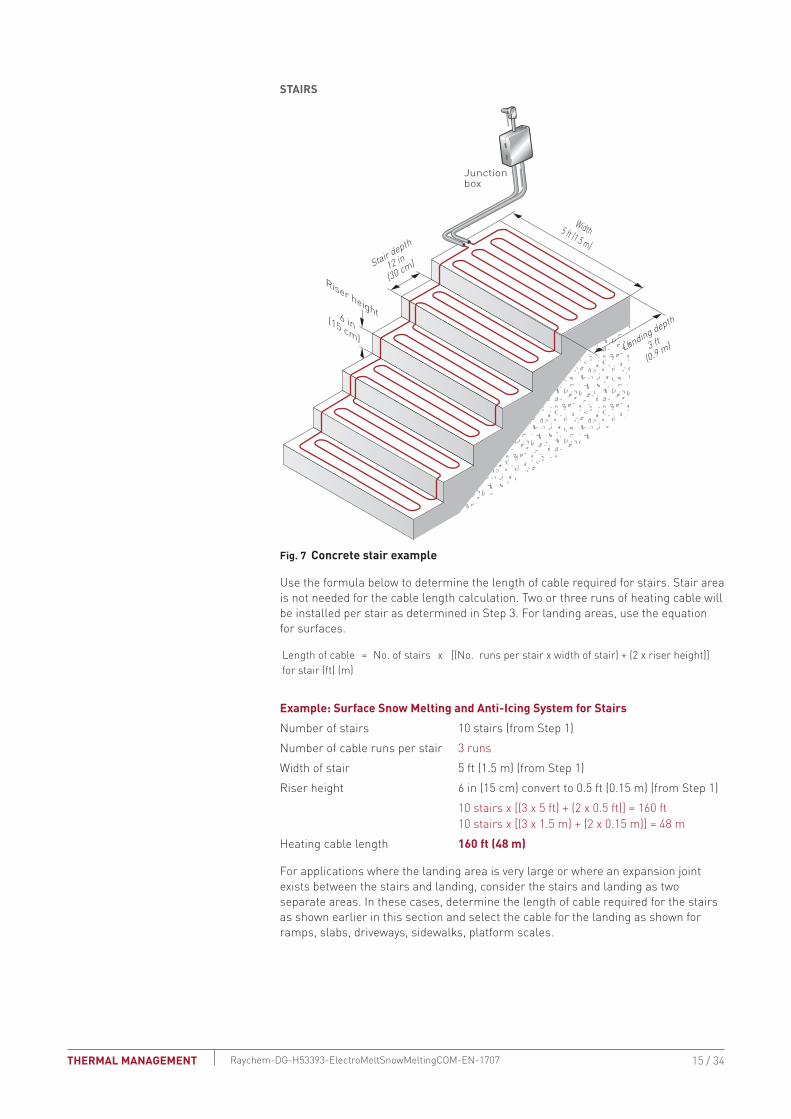

Surface Snow Melting and Anti-Icing
1 Determine design conditions
2 Select the heating cable
3 Determine the required watt density
4 Determine heating cable spacing
5 Determine the total area to be protected
9 Select the control system and power distribution
6 Determine heating cable length
7 Determine the electrical parameters
8 Select the connection kits and accessories
10 Complete the Bill of Materials
Step Determine the electrical parameters
This section will help you determine the electrical parameters for an ElectroMelt system including circuit breaker sizing and maximum circuit length Total required heating cable length divided by maximum circuit length will determine the number of circuits required for your snow melting solution
DETERMINE MAXIMUM CIRCUIT LENGTH
To determine maximum circuit length it is important to establish a minimum startup temperature for the system The following tables provide maximum circuit lengths based on minimum startup temperature circuit breaker rating and supply voltage Colder temperature startup requires shorter maximum circuit lengths The use of an automatic system which energizes the system above 20degF (ndash7degC) ensures that you can use maximum circuit lengths Manual control systems may require you to use shorter circuit lengths to compensate for startup below 20degF (ndash7degC)
A 30-mA ground-fault protection device (GFPD) must be used to provide protection from arcing or fire and to comply with warranty requirements agency certifications and national electrical codes If the heating cable is improperly installed or physically damaged sustained arcing or fire could result If arcing does occur the fault current may be too low to trip conventional circuit breakers
TAbLE 7 MAXIMUM CIRCUIT LENGTH FOR STARTUP AT 20degF (ndash7degC) IN FEET (METERS) USING AN AUTOMATIC SNOW CONTROL SYSTEM
Circuit breaker (A)
Heating cable supply voltage 208 V 240 V 277 V
15 80 (24) 85 (26) 100 (31)20 105 (32) 115 (35) 130 (40)30 160 (49) 170 (52) 195 (59)40 210 (64) 230 (70) 260 (79)50 265 (81) 285 (87) 325 (99)
TAbLE 8 MAXIMUM CIRCUIT LENGTH FOR STARTUP AT 0degF (ndash18degC) IN FEET (METERS) USING A MANUAL CONTROL SYSTEM
Circuit breaker (A)
Heating cable supply voltage 208 V 240 V 277 V
15 75 (23) 80 (24) 90 (27)20 100 (31) 110 (34) 120 (37)30 145 (44) 160 (49) 180 (55)40 200 (61) 210 (64) 240 (73)50 245 (75) 265 (81) 300 (91)
WARNING To minimize the danger of fire from sustained electrical arcing if the heating cable is damaged or improperly installed and to comply with the requirements of Thermal Management agency certifications and national electrical codes ground-fault equipment protection must be used on each heating cable branch circuit Arcing may not be stopped by conventional circuit protection
Example Surface Snow Melting and Anti-Icing System with Automatic Snow ControlStartup temperature 20degF (ndash7degC) (from Step 1)Circuit breakers 50 ASupply voltage 277 V (from Step 1)Maximum circuit length 325 ft (99 m) (from Table 7)
SURFACE SNOW MELTING AND ANTI-ICING ndash ELECTROMELT SYSTEM
16 34 THERMAL MANAGEMENTRaychem-DG-H53393-ElectroMeltSnowMeltingCOM-EN-1707
DETERMINE NUMbER OF CIRCUITS Use the following formula to determine number of circuits for the system
Number of circuits = Heating cable length required
Maximum heating cable circuit length
Example Surface Snow MeltingSurfacesTotal heating cable length 4800 ft (1427 m) (from Step 6)Maximum circuit length 325 ft (99 m) (from above)Number of circuits 4800 325 = 148 rounded to 15 circuitsStairsTotal heating cable length 160 ft (48 m) (from Step 6)Maximum circuit length 325 ft (99 m) (from above)Number of circuits 160 325 = 05 rounded to 1 circuit
Example Anti-Icing SystemSurfacesTotal heating cable length 5333 ft (1613 m) (from Step 6)Maximum circuit length 325 ft (99 m)Number of circuits 5333 325 = 164 rounded to 17 circuitsStairsTotal heating cable length 160 ft (48 m) (from Step 6)Maximum circuit length 325 ft (99 m) (from above)Number of circuits 160 325 = 05 rounded to 1 circuit
DETERMINE TRANSFORMER LOADThe total transformer load is the sum of load on all the circuit breakers in the system
Calculate the Circuit breaker Load (CbL) as
CBL (kW) = Circuit breaker rating (A) x 08 x Supply voltage
1000
Calculate the Total Transformer Load as follows
If the CBL is equal on all circuit breakers calculate the Total Transformer Load as
Total Transformer Load (kW) = CBL x Number of circuits
If the CBL is not equal on all circuit breakers calculate the Total Transformer Load as
Total Transformer Load (kW) = CBL1 + CBL2 + CBL3+ CBLN
17 34THERMAL MANAGEMENT Raychem-DG-H53393-ElectroMeltSnowMeltingCOM-EN-1707
Example Surface Snow MeltingCircuit breaker load (50 A x 08 x 277 V) 1000 = 111 kWTransformer Load 111 kW x 16 circuits = 1776 kW rounded to 178 kW 178 kW
Example Anti-Icing SystemCircuit breaker load (50 A x 08 x 277 V) 1000 = 111 kWTransformer load 111 kW x 18 circuits = 1998 kW rounded to 200 kW 200 kW
Surface Snow Melting and Anti-Icing
1 Determine design conditions
2 Select the heating cable
3 Determine the required watt density
4 Determine heating cable spacing
5 Determine the total area to be protected
9 Select the control system and power distribution
6 Determine heating cable length
7 Determine the electrical parameters
8 Select the connection kits and accessories
10 Complete the Bill of Materials
Step Select the connection kits and accessories
Thermal Management provides all the connection kits and accessories necessary to satisfy code approval agency and warranty requirements for the ElectroMelt system Additional heating cable will be required for connection kits and end terminations Adding the additional heating cable allowances needed with the heating cable length required for the layout will give you the total heating cable length required
Prepare a drawing of your system showing distinct circuits layout of cables connection kits expansion joints drains heated pathways for meltwater power connections junction boxes and sensors Determine length of cable from slab for power connection for all circuits If possible avoid crossing expansion crack control or other pavement joints Use the EMK-XEJ expansion joint kit to protect the heating cable if crossing is unavoidable
Junction boxes must be mounted above grade to prevent water entry Use an EMK-XJB or equivalent UL Listed or CSA Certified weatherproof junction box Protect heating cable from slab to junction box inside individual 1-inch rigid metal conduits Do not penetrate floors or walls with conduit nor insulate the conduit
SURFACE SNOW MELTING AND ANTI-ICING ndash ELECTROMELT SYSTEM
18 34 THERMAL MANAGEMENTRaychem-DG-H53393-ElectroMeltSnowMeltingCOM-EN-1707
TAbLE 9 CONNECTION KITS AND ACCESSORIESCatalog number Description
Standard packaging Usage
Heating cable allowance 1
Connection Kits
Power connection EMK-XP
End seal EMK-XP
EMK-XP Power connection and end seal kit
1 1 per circuit 3 ft (1 m) for connection plus conduit length for power connection and conduit length for end seal
EMK-XS Splice kit 1 As required 1 ft (30 cm)
Accessories
EMK-XJR Jacket repair kit 1 As required ndash
EMK-CT Nylon cable ties 100pack 1 per foot of cable used
ndash
EMK-XT Crimping tool 1 ndash ndash
SMCS Snow melt caution sign Dimensions 6 x 4 in (150 x 100 mm)
1 1 minimum per system
ndash
EMK-XEJ Expansion joint kit 1 1 per expansion joint crossing
1 12 ft (45 cm)
EMK-XJB Junction boxDimensions 15 12 x 11 34 x 7 58 in (394 x 299 x 194 mm)
1 1ndash2 ft (30ndash60 cm) for each end in the junction box
Maximum of two circuits per EMK-XJB
1 Allow extra heating cable for ease of component installation
19 34THERMAL MANAGEMENT Raychem-DG-H53393-ElectroMeltSnowMeltingCOM-EN-1707
Example Surface Snow Melting SystemNumber of circuits 15 for concrete slab + 1 for stairs = 16Power connection kits 16 power connection kitsConduit length (from slab to junction box) Power connection 15 ft (45 m) End seal 15 ft (45 m) (15 ft + 15 ft) x 16 circuits = 480 ft (45 m + 45 m) x 16 circuits = 144 mHeating cable allowance for each power connection 3 ft x 16 circuits = 48 ft 1 m x 16 circuits = 16 mTotal heating cable length required 528 ft (160 m)
Example Anti-Icing SystemNumber of circuits 17 for concrete slab + 1 for stairs = 18Power connection kits 18 power connection kitsConduit length (from slab to junction box) Power connection 15 ft (45 m) End seal 15 ft (45 m) (15 ft + 15 ft) x 18 circuits = 540 ft (45 m + 45 m) x 18 circuits = 162 mHeating cable allowance for each power connection 3 ft x 18 circuits = 54 ft 1 m x 18 circuits = 18 mTotal heating cable length required 594 ft (180 m)
SURFACE SNOW MELTING AND ANTI-ICING ndash ELECTROMELT SYSTEM
20 34 THERMAL MANAGEMENTRaychem-DG-H53393-ElectroMeltSnowMeltingCOM-EN-1707
Surface Snow Melting and Anti-Icing
1 Determine design conditions
2 Select the heating cable
3 Determine the required watt density
4 Determine heating cable spacing
5 Determine the total area to be protected
9 Select the control system and power distribution
6 Determine heating cable length
7 Determine the electrical parameters
8 Select the connection kits and accessories
10 Complete the Bill of Materials
Step Select the control system and power distribution
CONTROL SYSTEMS
Select a control system from the following three options but keep in mind that an automatic snow controller offers the highest system efficiency and the lowest operating cost bull Manual onoff controlbull Slab sensing thermostatbull Automatic snow melting controller
If the current rating of the control means is exceeded all three methods will require contactors sized to carry the load Each method offers a tradeoff balancing initial cost versus energy efficiency and ability to provide effective snow melting If the system is not energized when required snow will accumulate If the system is energized when it is not needed there will be unnecessary power consumption Choose the control method that best meets the project performance requirements For additional information refer to the ldquoTypical Control Diagramsrdquo Table 7 or contact your Thermal Management representative for details
Manual OnOff ControlA manually controlled system is operated by a switch that controls the system power contactor This method requires constant supervision to work effectively A manual system can be controlled by a building management system
Slab Sensing ThermostatA slab sensing thermostat can be used to energize the system whenever the slab temperature is below freezing but is not energy efficient when used as the sole means of control The slab sensing thermostat is recommended for all snow melting applications even when an automatic snow controller is used and is required for all asphalt and paver installations (for asphalt it prevents surface damage due to overheating)
Automatic Snow Melting ControllerWith an automatic snow controller the snow melting system is automatically energized when both precipitation and low temperature are detected When precipitation stops or the ambient temperature rises above freezing the system is de-energized In addition a slab sensor de-energizes the system after the slab reaches the slab sensing set point even if freezing precipitation is still present Using an automatic snow controller with a slab sensor offers the most energy-efficient control solution
For areas where a large number of circuits are required the Raychem ACS-30 can be used The Surface Snow Melting control mode in the ACS-30 includes an External Device control option This option allows a SnowMoisture sensing controller (from Table 10) to be integrated into the ACS-30 system Note that sensors (snow or gutter) cannot be directly connected to the ACS-30 system Refer to the ACS-30 Programming Guide (H58692) for more information on system setup
21 34THERMAL MANAGEMENT Raychem-DG-H53393-ElectroMeltSnowMeltingCOM-EN-1707
CIT-1snow sensor
To power supply or incorporate the ETI snow melting control system into a power distribution panel
APS-4C (shown) with SC-40C satelllitecontactor or APS-3C snow controller
OptionalSC-40Csatellite contactor
To additionalSC-40C satellitecontactors
To heating cable(s)
To heating cable(s)
Optional RCU-3 or RCU-4 remote control unit
To power supply
SIT-6E pavement mounted sensor
Environmental Technology Inc (ETI) of South Bend Indiana offers a complete line of automatic controllers for snow melting applications
Fig 8 Automatic snow melting control system
TAbLE 10 CONTROL SYSTEMS Catalog number Description
Slab Sensing ThermostatECW-GF Electronic ambient sensing controller with 30-mA ground-fault protection The control-
ler can be programmed to maintain temperatures up to 200degF (93degC) at voltages from 100 to 277 V and can switch current up to 30 Amperes The ECW-GF is complete with a 25-ft (76-m) temperature sensor and is housed in a Type 4X rated enclosure The controller features an ACDC dry alarm contact relay
An optional ground-fault display panel (ECW-GF-DP) that can be added to provide ground-fault or alarm indication in applications where the controller is mounted in inaccessible locations
ECW-GF-DP An optional remote display panel (ECW-GF-DP) can be added to provide ground-fault or alarm indication in applications where the controller is mounted in inaccessible locations
HEATER CYCLE
PD Pro Automatic snow and ice melting controller for pavement sidewalks loading docks roofs gutters and downspouts in commercial and residential environments The PD Pro interfaces with up to two sensors (any combination of CIT-1 GIT-1 or SIT-6E) to meet site requirements The PD Pro is housed in an environmentally-sheltered Type 4X enclosure and weighs only 3 pounds
GF Pro Automatic snow and ice melting controller for pavement sidewalks loading docks roofs gutters and downspouts in commercial and residential environments The GF Pro interfaces with up to two sensors (any combination of CIT-1 GIT-1 or SIT-6E) to meet site requirements The GF Pro is housed in an environmentally-sheltered Type 4X enclosure and weighs only 3 pounds
Features a built-in 30 mA self-testing Ground-Fault Equipment Protection (GFEP) capability digitally filtered to minimize false tripping A ground-fault alarm must be manually reset using the TestReset switch before heater operation can continue
SURFACE SNOW MELTING AND ANTI-ICING ndash ELECTROMELT SYSTEM
22 34 THERMAL MANAGEMENTRaychem-DG-H53393-ElectroMeltSnowMeltingCOM-EN-1707
TAbLE 10 CONTROL SYSTEMS Catalog number Description
Automatic Snow Melting ControllersAPS-3C Automatic snow melting controller housed in a Type 3R enclosure provides effective
economical automatic control of all snow melting applications Features include 120 V or 208ndash240 V models 24-A DPDT output relay and an adjustable hold-on timer
Enclosure dimensions 11-12 in x 9-18 in x 6-916 in (292 mm x 232 mm x 167 mm)
APS-4C Automatic snow melting controller housed in a Type 3R enclosure provides effective economical automatic control of all snow melting applications The APS-4C can oper-ate with any number of SC-40C satellite contactors for larger loads Features include 277 V single-phase or 208ndash240 277480 and 600 V three-phase models built-in 3-pole contactor integral 30 mA ground-fault circuit interrupter and an adjustable hold-on timer
Enclosure dimensions 11-12 in x 9-18 in x 6-916 in (292 mm x 232 mm x 167 mm)
SC-40C Satellite contactor power control peripheral for an APS-4C snow melting control-ler housed in a Type 3R enclosure Features include 277 V single-phase or 208ndash240 277480 and 600 V three-phase models built-in 3-pole contactor and integral 30 mA ground-fault circuit interrupter
Enclosure dimensions 11-12 in x 9-18 in x 6 in (292 mm x 232 mm x 152 mm)
Snow Melting and Gutter De-Icing Sensors and Accessories
CIT-1 Overhead snow sensor that detects precipitation or blowing snow at ambient temper-atures below 38degF (33degC) For use with either an APS-3C or APS-4C automatic snow melting controller
SIT-6E Pavement-mounted sensor signals for the heating cable to turn on when the pavement temperature falls below 38degF (33degC) and precipitation in any form is present Microcontroller technology effectively eliminates ice bridging while ensuring accurate temperature measurement For use with either an APS-3C or APS-4C automatic snow melting controller
RCU-3 The RCUndash3 provides control and status display to the APSndash3C controller from a remote location It has a 2 4 6 or 8 hour CYCLE TIME adjustment independent of APS-3C setting
RCU-4 The RCUndash4 provides control and status display to the APSndash4C controller and SC-40C Satellite Contactor from a remote location It has a 2 4 6 or 8 hour CYCLE TIME adjustment independent of the APS-4C or SC-40C setting
23 34THERMAL MANAGEMENT Raychem-DG-H53393-ElectroMeltSnowMeltingCOM-EN-1707
TAbLE 10 CONTROL SYSTEMS Catalog number Description
Electronic Controllers
ACS-UIT2ACS-PCM2-5
The Raychem ACS-30 Advanced Commercial Control System is a multipoint electronic control and monitoring system for heat-tracing used in various commercial applications such as pipe freeze protection roof and gutter de-icing surface snow melting hot water temperature maintenance and floor heating The Raychem ACS-30 system can control up to 260 circuits with multiple networked ACS-PCM2-5 panels with a single ACS-UIT2 user interface terminal The ACS-PCM2-5 panel can directly control up to 5 individual heat-tracing circuits using electromechanical relays rated at 30 A up to 277 V
By FieldServer TechnologieswwwProtoCessorcom
PROTOCESSORSERIAL ETHERNET
PROTONODE
FRAME GND- PWR+PWR
RS 485+RS 485 -RS 485 GND
S3S2S1S0B3B2B1B0
A7A6A5A4A3A2A1A0
ProtoNode-RER The Raychem ProtoNode is an external high performance multi-protocol gateway for customers needing protocol translation between Building Management Systems (BMS) and the Raychem ACS-30 or C910-485 controllers
The ProtoNode-RER is for BACnetreg or Metasysreg N2 systems
RTD-200 RTD10CSRTD50CS
Stainless steel jacketed three-wire RTD (Resistance Temperature Detector) used with Raychem C910-485 and ACS-30 controllers
RTD-200 3-in (76 mm) temperature sensor with a 6-ft (18 m) lead wire and 12-in NPT bushing
RTD10CS temperature sensor with a 10-ft (3 m) flexible armor 18-in (457 mm) lead wire and 12-inch NPT bushing
RTD50CS temperature sensor with a 50-ft (3 m) flexible armor 18-in (457 mm) lead wire and 12-in NPT bushing
POWER DISTRIbUTION
Single Circuit ControlHeating cable circuits that do not exceed the current rating of the selected temperature control can be switched directly (see Fig 9)
Group ControlIf the current draw exceeds the switch rating or if the controller will activate more than one circuit or group control an external contactor must be used (see Fig 9)
Large systems with many circuits should use an SMPG power distribution panel The SMPG is a dedicated power-distribution control ground-fault protection monitoring and alarm panel for surface snow melting and anti-icing applications This enclosure contains an assembled circuit-breaker panelboard Panels are equipped with ground-fault circuit breakers with or without alarm contacts The group control package allows the system to operate automatically in conjunction with an ambient-sensing thermostat individual electronic or duty cycle controller
SURFACE SNOW MELTING AND ANTI-ICING ndash ELECTROMELT SYSTEM
24 34 THERMAL MANAGEMENTRaychem-DG-H53393-ElectroMeltSnowMeltingCOM-EN-1707
Single circuit control Group control
Temperaturecontroller
1-poleGFEP breaker
1N
G
Heatingcable
oslashoslash supply
C
Temperaturecontroller
Contactor
1-poleGFEP breaker
N
G (Typ 3)
oslash2
oslash1
oslash3
3-phase 4-wiresupply (WYE)
3-pole mainbreaker
oslash
oslash 1 supply
N
Heating cable sheath braid or ground
Heating cable sheath braid or ground
Fig 9 Single circuit and group control
Exterior View Interior View
NP
NP
NP
NP
G
NP
NP
G
NP
R
NP
Nameplate
Mounting brackets
Heater thermostat(3R only)
Power on lightHTC energized light
CB tripped alarm
Heater (3R only)
Door lock handle
SnowIcemelt controller
Ground bar
Panelboardlugs
Control wiring
Heater cycle atimed control
EUR - 5A
Main breaker(optional)
Heat tracecontactor
Branch breakers(2 pole)
Panelboard
Fig 10 SMPG1 power distribution panel
N
Three-pole main contactor
FuseMain circuit breaker (optional)
Incomingpower
GND
24 V
One-pole with 30-mAground-fault trip (277 V)
Remote annunciation alarm(circuit breaker
with alarm type 3)
GIT-1
CIT-1
SIT-6E
Braid
Aerialsnow sensor
Gutterice sensor
Slabtemperature sensor
Pavement-mountedsensor
Single Oslashconnection
SNOWICE
SUPPLY
EUR-5A SNOW SWITCHAUTOMATIC SNOWICE MELTING CONTROL PANEL
HEATER
HEATERCYCLE
HOURS
0
45degF
50degF
55degF
60degF65degF
70degF
75degF
80degF
85degF
2
4 6
8
10
TEMPERATURE
Control transformer
Fig 11 Typical wiring diagram of group control with SMPG1
25 34THERMAL MANAGEMENT Raychem-DG-H53393-ElectroMeltSnowMeltingCOM-EN-1707
TAbLE 11 POWER DISTRIbUTIONCatalog number Description
Power Distribution and Control Panels
NP
NP
NP
NP
NP
NP
NP
SMPG1 Single-phase power distribution panel that includes ground-fault protection monitor-ing and control for snow melting systems Single-phase voltages include 208 and 277 V
If standard configurations do not meet your needs custom SMPG panels are available and processed under the catalog number SMPG-GENERAL part number P000000763 Please contact your Thermal Management representative for a custom SMPG panel quotation
Example Surface Snow Melting SystemThis system has 16 circuits and will require a specially designed control panel As many as eight SIT-6E sensors can be used in this configuration The amount depends upon designer preference
Example Anti-Icing SystemThis system has 18 circuits and will require a specially designed control panel As many as eight SIT-6E sensors can be used in this configuration The amount depends upon designer preference
SURFACE SNOW MELTING AND ANTI-ICING ndash ELECTROMELT SYSTEM
26 34 THERMAL MANAGEMENTRaychem-DG-H53393-ElectroMeltSnowMeltingCOM-EN-1707
Surface Snow Melting amp Anti-Icing
1 Determine design conditions
2 Select the heating cable
3 Determine the required watt density
4 Determine heating cable spacing
5 Determine the total area to be protected
9 Select the control system and power distribution
6 Determine heating cable length
7 Determine the electrical parameters
8 Select the connection kits and accessories
10 Complete the Bill of Materials
Step 0 Complete the bill of Materials
If you used the Design Worksheet to document all your design parameters you should have all the details you need to complete the Bill of Materials
27 34THERMAL MANAGEMENT Raychem-DG-H53393-ElectroMeltSnowMeltingCOM-EN-1707
ELECTROMELT SYSTEM SURFACE SNOW MELTING AND ANTI-ICING DESIGN WORKSHEET
Step Determine design conditions
Application Size and layoutSupply voltage Phase Control method
Surface snow melting Geographical location _____________________
Anti-icing Minimum ambient temperature _____________________ Average wind speed during freezing periods (mphkmph) ____________________
Paving material Concrete pavement In concrete under paving stones
Slab surface (ftm) __________________Ramp surface (ftm) _________________ Stairs Number of stairs ______________ Width of stair (ftm) ______________ Riser height (incm) ______________ Depth of stair (incm) ______________ Landing dimensions (ftm) ______________Wheel tracks Track length (ftm) ____________
208 V
240 V
277 V
Single-phase Manual onoff control Slab-sensing thermostat Automatic snow melting
controller
Example9 Surface snow melting9 buffalo NY9 Concrete slab
Slab surface 80 ft x 50 ftStairs Number of stairs 10 Width of stair 5 ft Riser height 6 in Depth of stair 12 in
9 277 V 9 Single-phase 9 Automatic snow melting controller
Step Select the heating cableSee Table 1 EM2-XR
Example9 EM2-XR
Step Determine the required watt densitySurface snow melting
See Table 2Anti-icing
See Table 3 and Table 4
Geographical location _________________________Required watt density (Wft2)(Wm2) ___________________________
Minimum ambient temperature (degFdegC) _______
Average wind speed during freezing periods (mphkmph) ______
Required watt density (Wft2)(Wm2) _______
ExampleGeographical location buffalo NYRequired watt density 40 Wft2
SURFACE SNOW MELTING AND ANTI-ICING ndash ELECTROMELT SYSTEM
28 34 THERMAL MANAGEMENTRaychem-DG-H53393-ElectroMeltSnowMeltingCOM-EN-1707
Step Determine heating cable spacingSee Table 5
34 Wft
12 in 3
3Equally spaced across the width of the stairwith one run 2 in from the front edge
40 Wft2 10 in
Power output (Wft) Watt density (Wft2)
x( )Heating cable spacing (in)
12 inftPower output (Wft)
Stairs
Surfaces
Surfaces
Calculate the heating cable needed for stairs and landing
Determine the number of cable runs needed
Depth of stair lt105 in (27 cm) 2 cable runs
Depth of stair 105ndash12 in (27ndash30 cm) 3 cable runs
Cable runs needed
Concrete stair depth (incm) Number of cable runs Spacing
StairsCalculate the heating cable needed for stairs and landing
Determine the number of cable runs needed
Depth of stair lt105 in (27 cm) 2 cable runs
Depth of stair 105ndash12 in (27ndash30 cm) 3 cable runs
Cable runs needed
x( )12 inft
=Watt density (Wft2)
Example
Note Round result to the nearest whole number of inches or centimeters
Heating cable spacing (incm)=
Concrete stair depth (incm) Number of cable runs Spacing
Note Round result to the nearest whole number of inches or centimeters
Step Determine the total area to be protected
x80 ft 4000 ft2
Length
50 ft
Width
xSurface area to be protected (ft2m2)Length (ftm) Width (ftm)
=
Example
Surfaces
Surface area to be protected (ft)=
29 34THERMAL MANAGEMENT Raychem-DG-H53393-ElectroMeltSnowMeltingCOM-EN-1707
Step Determine the heating cable length
xHeating cable length for surface
4000 ft2
12 in10 in 4800
Total concrete slab area
Calculate the heating cable for stairs and landing
=Heating cable spacing
x x x =
=
=
=
=
+( () )10
No of stairs
32
No of runs per stair
5 ft
Width of stair
05 ft
Riser height
160 ft
4960 ft
Heating cable length for stairs[ ]
Note Additional heating cable for connection kits and end terminations is calculated in Step 8
Calculate the heating cable for stairs and landing
Surfaces
Surfaces
x x x+( () )No of stairs
2No of runs per stair Width of stair (ftm) Riser height (ftm) Heating cable length for stairs (ftm)
[ ]
Note Additional heating cable for connection kits and end terminations is calculated in Step 8
Example
xHeating cable length for surface (ftm)
12 inTotal concrete slab area (ft2m2)
Heating cable spacing (incm)
Calculate heating cable needed for wheel tracks
x 2 x 4 runsWheel track to be protected (ftm)Length (ftm)
Total heating cable length required (ftm)
Total heating cable length required
SURFACE SNOW MELTING AND ANTI-ICING ndash ELECTROMELT SYSTEM
30 34 THERMAL MANAGEMENTRaychem-DG-H53393-ElectroMeltSnowMeltingCOM-EN-1707
Step Determine the electrical parametersSee Table 7 and Table 8
Number of circuits
4800 ft 325 ft 148 rounded to 15
Heating cable length required for surface =
Maximum heating cable circuit length
Determine number of circults Surfaces
Number of circuitsHeating cable length required for surface (ftm) =
Maximum heating cable circuit length (ftm)
Determine number of circults
Circuit breaker load (kW)08 1000
Circuit breaker rating (Amps )x x ( ) =
Supply voltage
Determine total transformer load
Calculate the total transformer load as follows
Calculate circuit breaker load (CBL)
If the CBL is equal on all circuits calculate the transformer load as
If the CBL is NOT equal on all circuits calculate the transformer load as
Total transformer load (kW)Circuit breaker load (kW)x =
Number of breakers
Total transformer load (kW)CBL1 + CBL2 + CBL3 + CBLN
=
Example
Number of circuits
160 ft 325 ft 05 rounded to 1
Heating cable length required for surface =
Maximum heating cable circuit length
Determine number of circults Stair
Circuit breaker load (kW)
50 A 277 V08 1000
111 kW
Circuit breaker ratingx x ( ) =
Supply voltage
Total transformer load (kW)
111 kW 16 1776 kW rounded to 178
Circuit breaker load (kW)x =
Determine transformer load
Number of breakers
31 34THERMAL MANAGEMENT Raychem-DG-H53393-ElectroMeltSnowMeltingCOM-EN-1707
Step Select the connection kit and accessoriesSee Table 9
Connection kits Description QuantityHeating cable allowance
T EMK-XP
T EMK-XS
Power connection and end seal kit
Splice kit____________
____________
__________________
__________________
Accessories Description Quantity
T EMK-XJR
T EMK-CT
T EMK-XT
T SMCS
T EMK-XEJ
T EMK-XJB
Jacket repair kit
Nylon cable ties
Crimping tool
Snow melt caution sign
Expansion joint kit
Junction box
____________
____________
____________
____________
____________
____________
__________________
__________________
+ =Total heating cable
length requiredTotal heating cable allowance for connection kitsTotal heating cable length
Total heating cableallowance for connection kits
15 1 16 16
15 ft 15 ft 480 ft
480 ft
16
3 ft 16 48 ft
48 ft
630 ft 63 693 ft
528 ft
Total no of circuitsNumber circuits for concrete slab+ =
Total no of power connection kits=
Circuit(s) for stairs+
Circuit(s) for expansion joints
Total conduit length (ftm)Power connection conduit length(slab to junction box) (ftm)
+ x( ) =End seal conduit length
(slab to junction box) (ftm)Total number of circuits
Total heating cable allowanceper power connection (ftm)
Cable allowance per circuit connection (ftm)
x =Total number of circuits
Total additionalheating cable (ftm)
Total conduit length (ftm)+ =
=Total heating cable with
connection kit allowance (ftm)
Total allowance per power connection kit (ftm)
Total heating cable length (ftm) Total heating cable allowance (ftm)+
Example
Total no of circuitsNumber circuits for concrete slab+ =
Total no of power connection kits=
Circuit(s) for stairs+
Circuit(s) for expansion joints
Total conduit lengthPower connection conduit length(slab to junction box)
+ x( ) =End seal conduit length
(slab to junction box)Total number of circuits
Total heating cable allowanceper power connection
Cable allowance per circuit connection
x =Total number of circuits
Total additional heating cableTotal conduit length+ =
=Total heating cable withconnection kit allowance
Total allowance per power connection kit
Total heating cable length Total heating cable allowance+
SURFACE SNOW MELTING AND ANTI-ICING ndash ELECTROMELT SYSTEM
32 34 THERMAL MANAGEMENTRaychem-DG-H53393-ElectroMeltSnowMeltingCOM-EN-1707
Step Select the control system and power distribution Control SystemsSee Table 10Thermostats controllers and accessories Description Quantity
T ECW-GF
T ECW-GF-DP
T PD Pro
T GF-Pro
T APS-3C
T APS-4C
T SC-40C
T CIT-1
T SIT-6E
T RCU-3
T RCU-4
T ACS-UIT2
T ACS-PCM2-5
T ProtoNode-RER
T RTD3CS
T RTD10CS
T RTD-200
T RTD50CS
Electronic thermostat with 25-ft sensor
Remote display panel for ECW-GF
Automatic snow and ice melting controllerAutomatic snow and ice melting controllerAutomatic snow and ice melting controllerAutomatic snow and ice melting controllerSatellite contactor
Overhead snow sensor
Pavement-mounted sensor
Remote control unit for APS-3C
Remote control unit for APS-4C
ACS-30 user interface terminal
ACS-30 power control panel
Multi-protocol gateway
Resistance temperature device for Raychem ACS-30
Resistance temperature device for Raychem ACS-30
Resistance temperature device for Raychem ACS-30
Resistance temperature device for Raychem ACS-30
____________
____________
____________
____________
____________
____________
____________
____________
____________
____________
____________
____________
____________
____________
____________
____________
____________
____________
Power DistributionSee Table 11
Power distribution and control panels Description Quantity
T SMPG1 Single-phase power distribution panel ____________
Step Complete the bill of Materials
Use the information recorded in this worksheet to complete the Bill of Materials
33 34THERMAL MANAGEMENT Raychem-DG-H53393-ElectroMeltSnowMeltingCOM-EN-1707
NORTH AMERICA Tel +18005456258Fax +18005275703Tel +16502161526Fax +16504747711thermalinfopentaircom
Pentair is owned by Pentair or its global affiliates All other trademarks are the property of their respective owners Pentair reserves the right to change specifications without prior notice
copy 2009-2017 Pentair
WWWPENTAIRTHERMALCOM
34 34THERMAL MANAGEMENT Raychem-DG-H53393-ElectroMeltSnowMeltingCOM-EN-1707
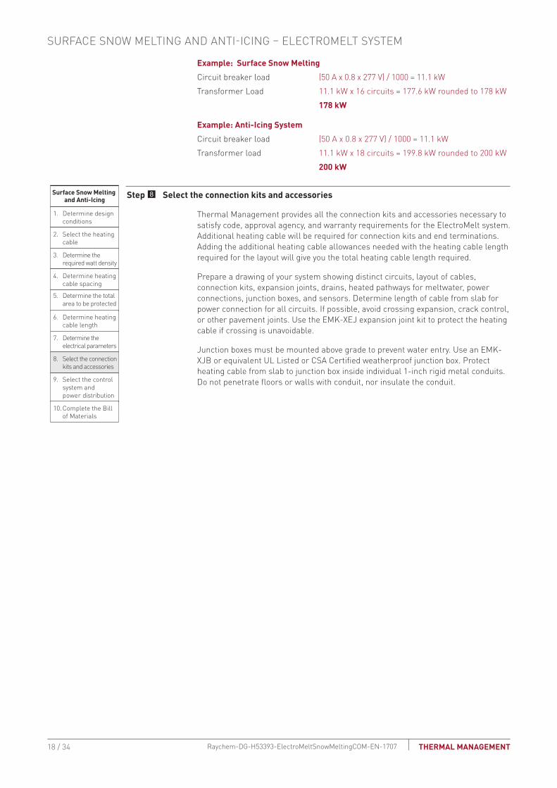
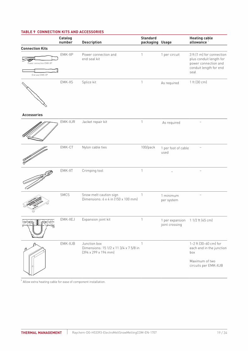
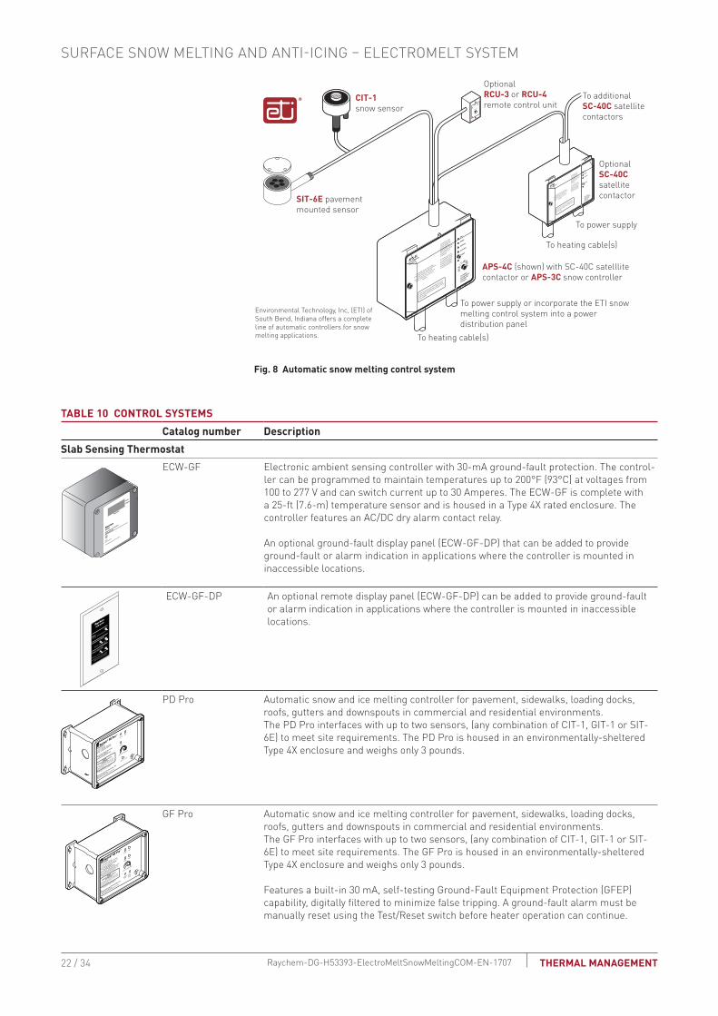
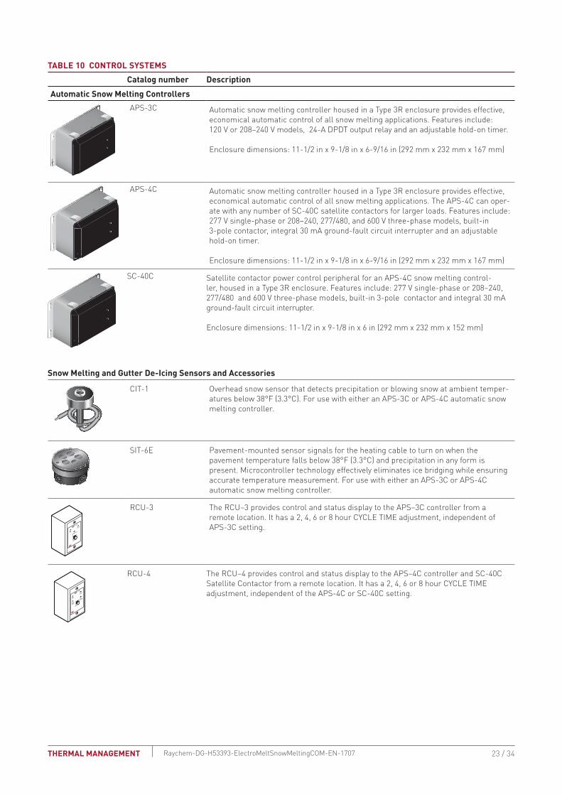
TAbLE 10 CONTROL SYSTEMS Catalog number Description
Automatic Snow Melting ControllersAPS-3C Automatic snow melting controller housed in a Type 3R enclosure provides effective
economical automatic control of all snow melting applications Features include 120 V or 208ndash240 V models 24-A DPDT output relay and an adjustable hold-on timer
Enclosure dimensions 11-12 in x 9-18 in x 6-916 in (292 mm x 232 mm x 167 mm)
APS-4C Automatic snow melting controller housed in a Type 3R enclosure provides effective economical automatic control of all snow melting applications The APS-4C can oper-ate with any number of SC-40C satellite contactors for larger loads Features include 277 V single-phase or 208ndash240 277480 and 600 V three-phase models built-in 3-pole contactor integral 30 mA ground-fault circuit interrupter and an adjustable hold-on timer
Enclosure dimensions 11-12 in x 9-18 in x 6-916 in (292 mm x 232 mm x 167 mm)
SC-40C Satellite contactor power control peripheral for an APS-4C snow melting control-ler housed in a Type 3R enclosure Features include 277 V single-phase or 208ndash240 277480 and 600 V three-phase models built-in 3-pole contactor and integral 30 mA ground-fault circuit interrupter
Enclosure dimensions 11-12 in x 9-18 in x 6 in (292 mm x 232 mm x 152 mm)
Snow Melting and Gutter De-Icing Sensors and Accessories
CIT-1 Overhead snow sensor that detects precipitation or blowing snow at ambient temper-atures below 38degF (33degC) For use with either an APS-3C or APS-4C automatic snow melting controller
SIT-6E Pavement-mounted sensor signals for the heating cable to turn on when the pavement temperature falls below 38degF (33degC) and precipitation in any form is present Microcontroller technology effectively eliminates ice bridging while ensuring accurate temperature measurement For use with either an APS-3C or APS-4C automatic snow melting controller
RCU-3 The RCUndash3 provides control and status display to the APSndash3C controller from a remote location It has a 2 4 6 or 8 hour CYCLE TIME adjustment independent of APS-3C setting
RCU-4 The RCUndash4 provides control and status display to the APSndash4C controller and SC-40C Satellite Contactor from a remote location It has a 2 4 6 or 8 hour CYCLE TIME adjustment independent of the APS-4C or SC-40C setting
23 34THERMAL MANAGEMENT Raychem-DG-H53393-ElectroMeltSnowMeltingCOM-EN-1707
TAbLE 10 CONTROL SYSTEMS Catalog number Description
Electronic Controllers
ACS-UIT2ACS-PCM2-5
The Raychem ACS-30 Advanced Commercial Control System is a multipoint electronic control and monitoring system for heat-tracing used in various commercial applications such as pipe freeze protection roof and gutter de-icing surface snow melting hot water temperature maintenance and floor heating The Raychem ACS-30 system can control up to 260 circuits with multiple networked ACS-PCM2-5 panels with a single ACS-UIT2 user interface terminal The ACS-PCM2-5 panel can directly control up to 5 individual heat-tracing circuits using electromechanical relays rated at 30 A up to 277 V
By FieldServer TechnologieswwwProtoCessorcom
PROTOCESSORSERIAL ETHERNET
PROTONODE
FRAME GND- PWR+PWR
RS 485+RS 485 -RS 485 GND
S3S2S1S0B3B2B1B0
A7A6A5A4A3A2A1A0
ProtoNode-RER The Raychem ProtoNode is an external high performance multi-protocol gateway for customers needing protocol translation between Building Management Systems (BMS) and the Raychem ACS-30 or C910-485 controllers
The ProtoNode-RER is for BACnetreg or Metasysreg N2 systems
RTD-200 RTD10CSRTD50CS
Stainless steel jacketed three-wire RTD (Resistance Temperature Detector) used with Raychem C910-485 and ACS-30 controllers
RTD-200 3-in (76 mm) temperature sensor with a 6-ft (18 m) lead wire and 12-in NPT bushing
RTD10CS temperature sensor with a 10-ft (3 m) flexible armor 18-in (457 mm) lead wire and 12-inch NPT bushing
RTD50CS temperature sensor with a 50-ft (3 m) flexible armor 18-in (457 mm) lead wire and 12-in NPT bushing
POWER DISTRIbUTION
Single Circuit ControlHeating cable circuits that do not exceed the current rating of the selected temperature control can be switched directly (see Fig 9)
Group ControlIf the current draw exceeds the switch rating or if the controller will activate more than one circuit or group control an external contactor must be used (see Fig 9)
Large systems with many circuits should use an SMPG power distribution panel The SMPG is a dedicated power-distribution control ground-fault protection monitoring and alarm panel for surface snow melting and anti-icing applications This enclosure contains an assembled circuit-breaker panelboard Panels are equipped with ground-fault circuit breakers with or without alarm contacts The group control package allows the system to operate automatically in conjunction with an ambient-sensing thermostat individual electronic or duty cycle controller
SURFACE SNOW MELTING AND ANTI-ICING ndash ELECTROMELT SYSTEM
24 34 THERMAL MANAGEMENTRaychem-DG-H53393-ElectroMeltSnowMeltingCOM-EN-1707
Single circuit control Group control
Temperaturecontroller
1-poleGFEP breaker
1N
G
Heatingcable
oslashoslash supply
C
Temperaturecontroller
Contactor
1-poleGFEP breaker
N
G (Typ 3)
oslash2
oslash1
oslash3
3-phase 4-wiresupply (WYE)
3-pole mainbreaker
oslash
oslash 1 supply
N
Heating cable sheath braid or ground
Heating cable sheath braid or ground
Fig 9 Single circuit and group control
Exterior View Interior View
NP
NP
NP
NP
G
NP
NP
G
NP
R
NP
Nameplate
Mounting brackets
Heater thermostat(3R only)
Power on lightHTC energized light
CB tripped alarm
Heater (3R only)
Door lock handle
SnowIcemelt controller
Ground bar
Panelboardlugs
Control wiring
Heater cycle atimed control
EUR - 5A
Main breaker(optional)
Heat tracecontactor
Branch breakers(2 pole)
Panelboard
Fig 10 SMPG1 power distribution panel
N
Three-pole main contactor
FuseMain circuit breaker (optional)
Incomingpower
GND
24 V
One-pole with 30-mAground-fault trip (277 V)
Remote annunciation alarm(circuit breaker
with alarm type 3)
GIT-1
CIT-1
SIT-6E
Braid
Aerialsnow sensor
Gutterice sensor
Slabtemperature sensor
Pavement-mountedsensor
Single Oslashconnection
SNOWICE
SUPPLY
EUR-5A SNOW SWITCHAUTOMATIC SNOWICE MELTING CONTROL PANEL
HEATER
HEATERCYCLE
HOURS
0
45degF
50degF
55degF
60degF65degF
70degF
75degF
80degF
85degF
2
4 6
8
10
TEMPERATURE
Control transformer
Fig 11 Typical wiring diagram of group control with SMPG1
25 34THERMAL MANAGEMENT Raychem-DG-H53393-ElectroMeltSnowMeltingCOM-EN-1707
TAbLE 11 POWER DISTRIbUTIONCatalog number Description
Power Distribution and Control Panels
NP
NP
NP
NP
NP
NP
NP
SMPG1 Single-phase power distribution panel that includes ground-fault protection monitor-ing and control for snow melting systems Single-phase voltages include 208 and 277 V
If standard configurations do not meet your needs custom SMPG panels are available and processed under the catalog number SMPG-GENERAL part number P000000763 Please contact your Thermal Management representative for a custom SMPG panel quotation
Example Surface Snow Melting SystemThis system has 16 circuits and will require a specially designed control panel As many as eight SIT-6E sensors can be used in this configuration The amount depends upon designer preference
Example Anti-Icing SystemThis system has 18 circuits and will require a specially designed control panel As many as eight SIT-6E sensors can be used in this configuration The amount depends upon designer preference
SURFACE SNOW MELTING AND ANTI-ICING ndash ELECTROMELT SYSTEM
26 34 THERMAL MANAGEMENTRaychem-DG-H53393-ElectroMeltSnowMeltingCOM-EN-1707
Surface Snow Melting amp Anti-Icing
1 Determine design conditions
2 Select the heating cable
3 Determine the required watt density
4 Determine heating cable spacing
5 Determine the total area to be protected
9 Select the control system and power distribution
6 Determine heating cable length
7 Determine the electrical parameters
8 Select the connection kits and accessories
10 Complete the Bill of Materials
Step 0 Complete the bill of Materials
If you used the Design Worksheet to document all your design parameters you should have all the details you need to complete the Bill of Materials
27 34THERMAL MANAGEMENT Raychem-DG-H53393-ElectroMeltSnowMeltingCOM-EN-1707
ELECTROMELT SYSTEM SURFACE SNOW MELTING AND ANTI-ICING DESIGN WORKSHEET
Step Determine design conditions
Application Size and layoutSupply voltage Phase Control method
Surface snow melting Geographical location _____________________
Anti-icing Minimum ambient temperature _____________________ Average wind speed during freezing periods (mphkmph) ____________________
Paving material Concrete pavement In concrete under paving stones
Slab surface (ftm) __________________Ramp surface (ftm) _________________ Stairs Number of stairs ______________ Width of stair (ftm) ______________ Riser height (incm) ______________ Depth of stair (incm) ______________ Landing dimensions (ftm) ______________Wheel tracks Track length (ftm) ____________
208 V
240 V
277 V
Single-phase Manual onoff control Slab-sensing thermostat Automatic snow melting
controller
Example9 Surface snow melting9 buffalo NY9 Concrete slab
Slab surface 80 ft x 50 ftStairs Number of stairs 10 Width of stair 5 ft Riser height 6 in Depth of stair 12 in
9 277 V 9 Single-phase 9 Automatic snow melting controller
Step Select the heating cableSee Table 1 EM2-XR
Example9 EM2-XR
Step Determine the required watt densitySurface snow melting
See Table 2Anti-icing
See Table 3 and Table 4
Geographical location _________________________Required watt density (Wft2)(Wm2) ___________________________
Minimum ambient temperature (degFdegC) _______
Average wind speed during freezing periods (mphkmph) ______
Required watt density (Wft2)(Wm2) _______
ExampleGeographical location buffalo NYRequired watt density 40 Wft2
SURFACE SNOW MELTING AND ANTI-ICING ndash ELECTROMELT SYSTEM
28 34 THERMAL MANAGEMENTRaychem-DG-H53393-ElectroMeltSnowMeltingCOM-EN-1707
Step Determine heating cable spacingSee Table 5
34 Wft
12 in 3
3Equally spaced across the width of the stairwith one run 2 in from the front edge
40 Wft2 10 in
Power output (Wft) Watt density (Wft2)
x( )Heating cable spacing (in)
12 inftPower output (Wft)
Stairs
Surfaces
Surfaces
Calculate the heating cable needed for stairs and landing
Determine the number of cable runs needed
Depth of stair lt105 in (27 cm) 2 cable runs
Depth of stair 105ndash12 in (27ndash30 cm) 3 cable runs
Cable runs needed
Concrete stair depth (incm) Number of cable runs Spacing
StairsCalculate the heating cable needed for stairs and landing
Determine the number of cable runs needed
Depth of stair lt105 in (27 cm) 2 cable runs
Depth of stair 105ndash12 in (27ndash30 cm) 3 cable runs
Cable runs needed
x( )12 inft
=Watt density (Wft2)
Example
Note Round result to the nearest whole number of inches or centimeters
Heating cable spacing (incm)=
Concrete stair depth (incm) Number of cable runs Spacing
Note Round result to the nearest whole number of inches or centimeters
Step Determine the total area to be protected
x80 ft 4000 ft2
Length
50 ft
Width
xSurface area to be protected (ft2m2)Length (ftm) Width (ftm)
=
Example
Surfaces
Surface area to be protected (ft)=
29 34THERMAL MANAGEMENT Raychem-DG-H53393-ElectroMeltSnowMeltingCOM-EN-1707
Step Determine the heating cable length
xHeating cable length for surface
4000 ft2
12 in10 in 4800
Total concrete slab area
Calculate the heating cable for stairs and landing
=Heating cable spacing
x x x =
=
=
=
=
+( () )10
No of stairs
32
No of runs per stair
5 ft
Width of stair
05 ft
Riser height
160 ft
4960 ft
Heating cable length for stairs[ ]
Note Additional heating cable for connection kits and end terminations is calculated in Step 8
Calculate the heating cable for stairs and landing
Surfaces
Surfaces
x x x+( () )No of stairs
2No of runs per stair Width of stair (ftm) Riser height (ftm) Heating cable length for stairs (ftm)
[ ]
Note Additional heating cable for connection kits and end terminations is calculated in Step 8
Example
xHeating cable length for surface (ftm)
12 inTotal concrete slab area (ft2m2)
Heating cable spacing (incm)
Calculate heating cable needed for wheel tracks
x 2 x 4 runsWheel track to be protected (ftm)Length (ftm)
Total heating cable length required (ftm)
Total heating cable length required
SURFACE SNOW MELTING AND ANTI-ICING ndash ELECTROMELT SYSTEM
30 34 THERMAL MANAGEMENTRaychem-DG-H53393-ElectroMeltSnowMeltingCOM-EN-1707
Step Determine the electrical parametersSee Table 7 and Table 8
Number of circuits
4800 ft 325 ft 148 rounded to 15
Heating cable length required for surface =
Maximum heating cable circuit length
Determine number of circults Surfaces
Number of circuitsHeating cable length required for surface (ftm) =
Maximum heating cable circuit length (ftm)
Determine number of circults
Circuit breaker load (kW)08 1000
Circuit breaker rating (Amps )x x ( ) =
Supply voltage
Determine total transformer load
Calculate the total transformer load as follows
Calculate circuit breaker load (CBL)
If the CBL is equal on all circuits calculate the transformer load as
If the CBL is NOT equal on all circuits calculate the transformer load as
Total transformer load (kW)Circuit breaker load (kW)x =
Number of breakers
Total transformer load (kW)CBL1 + CBL2 + CBL3 + CBLN
=
Example
Number of circuits
160 ft 325 ft 05 rounded to 1
Heating cable length required for surface =
Maximum heating cable circuit length
Determine number of circults Stair
Circuit breaker load (kW)
50 A 277 V08 1000
111 kW
Circuit breaker ratingx x ( ) =
Supply voltage
Total transformer load (kW)
111 kW 16 1776 kW rounded to 178
Circuit breaker load (kW)x =
Determine transformer load
Number of breakers
31 34THERMAL MANAGEMENT Raychem-DG-H53393-ElectroMeltSnowMeltingCOM-EN-1707
Step Select the connection kit and accessoriesSee Table 9
Connection kits Description QuantityHeating cable allowance
T EMK-XP
T EMK-XS
Power connection and end seal kit
Splice kit____________
____________
__________________
__________________
Accessories Description Quantity
T EMK-XJR
T EMK-CT
T EMK-XT
T SMCS
T EMK-XEJ
T EMK-XJB
Jacket repair kit
Nylon cable ties
Crimping tool
Snow melt caution sign
Expansion joint kit
Junction box
____________
____________
____________
____________
____________
____________
__________________
__________________
+ =Total heating cable
length requiredTotal heating cable allowance for connection kitsTotal heating cable length
Total heating cableallowance for connection kits
15 1 16 16
15 ft 15 ft 480 ft
480 ft
16
3 ft 16 48 ft
48 ft
630 ft 63 693 ft
528 ft
Total no of circuitsNumber circuits for concrete slab+ =
Total no of power connection kits=
Circuit(s) for stairs+
Circuit(s) for expansion joints
Total conduit length (ftm)Power connection conduit length(slab to junction box) (ftm)
+ x( ) =End seal conduit length
(slab to junction box) (ftm)Total number of circuits
Total heating cable allowanceper power connection (ftm)
Cable allowance per circuit connection (ftm)
x =Total number of circuits
Total additionalheating cable (ftm)
Total conduit length (ftm)+ =
=Total heating cable with
connection kit allowance (ftm)
Total allowance per power connection kit (ftm)
Total heating cable length (ftm) Total heating cable allowance (ftm)+
Example
Total no of circuitsNumber circuits for concrete slab+ =
Total no of power connection kits=
Circuit(s) for stairs+
Circuit(s) for expansion joints
Total conduit lengthPower connection conduit length(slab to junction box)
+ x( ) =End seal conduit length
(slab to junction box)Total number of circuits
Total heating cable allowanceper power connection
Cable allowance per circuit connection
x =Total number of circuits
Total additional heating cableTotal conduit length+ =
=Total heating cable withconnection kit allowance
Total allowance per power connection kit
Total heating cable length Total heating cable allowance+
SURFACE SNOW MELTING AND ANTI-ICING ndash ELECTROMELT SYSTEM
32 34 THERMAL MANAGEMENTRaychem-DG-H53393-ElectroMeltSnowMeltingCOM-EN-1707
Step Select the control system and power distribution Control SystemsSee Table 10Thermostats controllers and accessories Description Quantity
T ECW-GF
T ECW-GF-DP
T PD Pro
T GF-Pro
T APS-3C
T APS-4C
T SC-40C
T CIT-1
T SIT-6E
T RCU-3
T RCU-4
T ACS-UIT2
T ACS-PCM2-5
T ProtoNode-RER
T RTD3CS
T RTD10CS
T RTD-200
T RTD50CS
Electronic thermostat with 25-ft sensor
Remote display panel for ECW-GF
Automatic snow and ice melting controllerAutomatic snow and ice melting controllerAutomatic snow and ice melting controllerAutomatic snow and ice melting controllerSatellite contactor
Overhead snow sensor
Pavement-mounted sensor
Remote control unit for APS-3C
Remote control unit for APS-4C
ACS-30 user interface terminal
ACS-30 power control panel
Multi-protocol gateway
Resistance temperature device for Raychem ACS-30
Resistance temperature device for Raychem ACS-30
Resistance temperature device for Raychem ACS-30
Resistance temperature device for Raychem ACS-30
____________
____________
____________
____________
____________
____________
____________
____________
____________
____________
____________
____________
____________
____________
____________
____________
____________
____________
Power DistributionSee Table 11
Power distribution and control panels Description Quantity
T SMPG1 Single-phase power distribution panel ____________
Step Complete the bill of Materials
Use the information recorded in this worksheet to complete the Bill of Materials
33 34THERMAL MANAGEMENT Raychem-DG-H53393-ElectroMeltSnowMeltingCOM-EN-1707
NORTH AMERICA Tel +18005456258Fax +18005275703Tel +16502161526Fax +16504747711thermalinfopentaircom
Pentair is owned by Pentair or its global affiliates All other trademarks are the property of their respective owners Pentair reserves the right to change specifications without prior notice
copy 2009-2017 Pentair
WWWPENTAIRTHERMALCOM
34 34THERMAL MANAGEMENT Raychem-DG-H53393-ElectroMeltSnowMeltingCOM-EN-1707
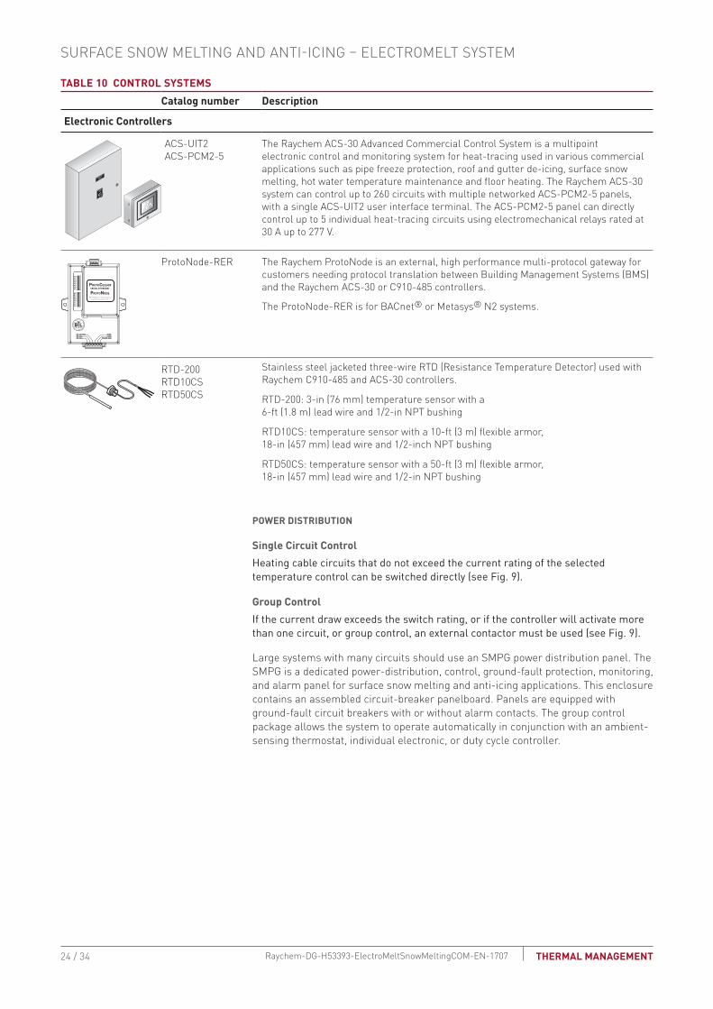
TAbLE 10 CONTROL SYSTEMS Catalog number Description
Electronic Controllers
ACS-UIT2ACS-PCM2-5
The Raychem ACS-30 Advanced Commercial Control System is a multipoint electronic control and monitoring system for heat-tracing used in various commercial applications such as pipe freeze protection roof and gutter de-icing surface snow melting hot water temperature maintenance and floor heating The Raychem ACS-30 system can control up to 260 circuits with multiple networked ACS-PCM2-5 panels with a single ACS-UIT2 user interface terminal The ACS-PCM2-5 panel can directly control up to 5 individual heat-tracing circuits using electromechanical relays rated at 30 A up to 277 V
By FieldServer TechnologieswwwProtoCessorcom
PROTOCESSORSERIAL ETHERNET
PROTONODE
FRAME GND- PWR+PWR
RS 485+RS 485 -RS 485 GND
S3S2S1S0B3B2B1B0
A7A6A5A4A3A2A1A0
ProtoNode-RER The Raychem ProtoNode is an external high performance multi-protocol gateway for customers needing protocol translation between Building Management Systems (BMS) and the Raychem ACS-30 or C910-485 controllers
The ProtoNode-RER is for BACnetreg or Metasysreg N2 systems
RTD-200 RTD10CSRTD50CS
Stainless steel jacketed three-wire RTD (Resistance Temperature Detector) used with Raychem C910-485 and ACS-30 controllers
RTD-200 3-in (76 mm) temperature sensor with a 6-ft (18 m) lead wire and 12-in NPT bushing
RTD10CS temperature sensor with a 10-ft (3 m) flexible armor 18-in (457 mm) lead wire and 12-inch NPT bushing
RTD50CS temperature sensor with a 50-ft (3 m) flexible armor 18-in (457 mm) lead wire and 12-in NPT bushing
POWER DISTRIbUTION
Single Circuit ControlHeating cable circuits that do not exceed the current rating of the selected temperature control can be switched directly (see Fig 9)
Group ControlIf the current draw exceeds the switch rating or if the controller will activate more than one circuit or group control an external contactor must be used (see Fig 9)
Large systems with many circuits should use an SMPG power distribution panel The SMPG is a dedicated power-distribution control ground-fault protection monitoring and alarm panel for surface snow melting and anti-icing applications This enclosure contains an assembled circuit-breaker panelboard Panels are equipped with ground-fault circuit breakers with or without alarm contacts The group control package allows the system to operate automatically in conjunction with an ambient-sensing thermostat individual electronic or duty cycle controller
SURFACE SNOW MELTING AND ANTI-ICING ndash ELECTROMELT SYSTEM
24 34 THERMAL MANAGEMENTRaychem-DG-H53393-ElectroMeltSnowMeltingCOM-EN-1707
Single circuit control Group control
Temperaturecontroller
1-poleGFEP breaker
1N
G
Heatingcable
oslashoslash supply
C
Temperaturecontroller
Contactor
1-poleGFEP breaker
N
G (Typ 3)
oslash2
oslash1
oslash3
3-phase 4-wiresupply (WYE)
3-pole mainbreaker
oslash
oslash 1 supply
N
Heating cable sheath braid or ground
Heating cable sheath braid or ground
Fig 9 Single circuit and group control
Exterior View Interior View
NP
NP
NP
NP
G
NP
NP
G
NP
R
NP
Nameplate
Mounting brackets
Heater thermostat(3R only)
Power on lightHTC energized light
CB tripped alarm
Heater (3R only)
Door lock handle
SnowIcemelt controller
Ground bar
Panelboardlugs
Control wiring
Heater cycle atimed control
EUR - 5A
Main breaker(optional)
Heat tracecontactor
Branch breakers(2 pole)
Panelboard
Fig 10 SMPG1 power distribution panel
N
Three-pole main contactor
FuseMain circuit breaker (optional)
Incomingpower
GND
24 V
One-pole with 30-mAground-fault trip (277 V)
Remote annunciation alarm(circuit breaker
with alarm type 3)
GIT-1
CIT-1
SIT-6E
Braid
Aerialsnow sensor
Gutterice sensor
Slabtemperature sensor
Pavement-mountedsensor
Single Oslashconnection
SNOWICE
SUPPLY
EUR-5A SNOW SWITCHAUTOMATIC SNOWICE MELTING CONTROL PANEL
HEATER
HEATERCYCLE
HOURS
0
45degF
50degF
55degF
60degF65degF
70degF
75degF
80degF
85degF
2
4 6
8
10
TEMPERATURE
Control transformer
Fig 11 Typical wiring diagram of group control with SMPG1
25 34THERMAL MANAGEMENT Raychem-DG-H53393-ElectroMeltSnowMeltingCOM-EN-1707
TAbLE 11 POWER DISTRIbUTIONCatalog number Description
Power Distribution and Control Panels
NP
NP
NP
NP
NP
NP
NP
SMPG1 Single-phase power distribution panel that includes ground-fault protection monitor-ing and control for snow melting systems Single-phase voltages include 208 and 277 V
If standard configurations do not meet your needs custom SMPG panels are available and processed under the catalog number SMPG-GENERAL part number P000000763 Please contact your Thermal Management representative for a custom SMPG panel quotation
Example Surface Snow Melting SystemThis system has 16 circuits and will require a specially designed control panel As many as eight SIT-6E sensors can be used in this configuration The amount depends upon designer preference
Example Anti-Icing SystemThis system has 18 circuits and will require a specially designed control panel As many as eight SIT-6E sensors can be used in this configuration The amount depends upon designer preference
SURFACE SNOW MELTING AND ANTI-ICING ndash ELECTROMELT SYSTEM
26 34 THERMAL MANAGEMENTRaychem-DG-H53393-ElectroMeltSnowMeltingCOM-EN-1707
Surface Snow Melting amp Anti-Icing
1 Determine design conditions
2 Select the heating cable
3 Determine the required watt density
4 Determine heating cable spacing
5 Determine the total area to be protected
9 Select the control system and power distribution
6 Determine heating cable length
7 Determine the electrical parameters
8 Select the connection kits and accessories
10 Complete the Bill of Materials
Step 0 Complete the bill of Materials
If you used the Design Worksheet to document all your design parameters you should have all the details you need to complete the Bill of Materials
27 34THERMAL MANAGEMENT Raychem-DG-H53393-ElectroMeltSnowMeltingCOM-EN-1707
ELECTROMELT SYSTEM SURFACE SNOW MELTING AND ANTI-ICING DESIGN WORKSHEET
Step Determine design conditions
Application Size and layoutSupply voltage Phase Control method
Surface snow melting Geographical location _____________________
Anti-icing Minimum ambient temperature _____________________ Average wind speed during freezing periods (mphkmph) ____________________
Paving material Concrete pavement In concrete under paving stones
Slab surface (ftm) __________________Ramp surface (ftm) _________________ Stairs Number of stairs ______________ Width of stair (ftm) ______________ Riser height (incm) ______________ Depth of stair (incm) ______________ Landing dimensions (ftm) ______________Wheel tracks Track length (ftm) ____________
208 V
240 V
277 V
Single-phase Manual onoff control Slab-sensing thermostat Automatic snow melting
controller
Example9 Surface snow melting9 buffalo NY9 Concrete slab
Slab surface 80 ft x 50 ftStairs Number of stairs 10 Width of stair 5 ft Riser height 6 in Depth of stair 12 in
9 277 V 9 Single-phase 9 Automatic snow melting controller
Step Select the heating cableSee Table 1 EM2-XR
Example9 EM2-XR
Step Determine the required watt densitySurface snow melting
See Table 2Anti-icing
See Table 3 and Table 4
Geographical location _________________________Required watt density (Wft2)(Wm2) ___________________________
Minimum ambient temperature (degFdegC) _______
Average wind speed during freezing periods (mphkmph) ______
Required watt density (Wft2)(Wm2) _______
ExampleGeographical location buffalo NYRequired watt density 40 Wft2
SURFACE SNOW MELTING AND ANTI-ICING ndash ELECTROMELT SYSTEM
28 34 THERMAL MANAGEMENTRaychem-DG-H53393-ElectroMeltSnowMeltingCOM-EN-1707
Step Determine heating cable spacingSee Table 5
34 Wft
12 in 3
3Equally spaced across the width of the stairwith one run 2 in from the front edge
40 Wft2 10 in
Power output (Wft) Watt density (Wft2)
x( )Heating cable spacing (in)
12 inftPower output (Wft)
Stairs
Surfaces
Surfaces
Calculate the heating cable needed for stairs and landing
Determine the number of cable runs needed
Depth of stair lt105 in (27 cm) 2 cable runs
Depth of stair 105ndash12 in (27ndash30 cm) 3 cable runs
Cable runs needed
Concrete stair depth (incm) Number of cable runs Spacing
StairsCalculate the heating cable needed for stairs and landing
Determine the number of cable runs needed
Depth of stair lt105 in (27 cm) 2 cable runs
Depth of stair 105ndash12 in (27ndash30 cm) 3 cable runs
Cable runs needed
x( )12 inft
=Watt density (Wft2)
Example
Note Round result to the nearest whole number of inches or centimeters
Heating cable spacing (incm)=
Concrete stair depth (incm) Number of cable runs Spacing
Note Round result to the nearest whole number of inches or centimeters
Step Determine the total area to be protected
x80 ft 4000 ft2
Length
50 ft
Width
xSurface area to be protected (ft2m2)Length (ftm) Width (ftm)
=
Example
Surfaces
Surface area to be protected (ft)=
29 34THERMAL MANAGEMENT Raychem-DG-H53393-ElectroMeltSnowMeltingCOM-EN-1707
Step Determine the heating cable length
xHeating cable length for surface
4000 ft2
12 in10 in 4800
Total concrete slab area
Calculate the heating cable for stairs and landing
=Heating cable spacing
x x x =
=
=
=
=
+( () )10
No of stairs
32
No of runs per stair
5 ft
Width of stair
05 ft
Riser height
160 ft
4960 ft
Heating cable length for stairs[ ]
Note Additional heating cable for connection kits and end terminations is calculated in Step 8
Calculate the heating cable for stairs and landing
Surfaces
Surfaces
x x x+( () )No of stairs
2No of runs per stair Width of stair (ftm) Riser height (ftm) Heating cable length for stairs (ftm)
[ ]
Note Additional heating cable for connection kits and end terminations is calculated in Step 8
Example
xHeating cable length for surface (ftm)
12 inTotal concrete slab area (ft2m2)
Heating cable spacing (incm)
Calculate heating cable needed for wheel tracks
x 2 x 4 runsWheel track to be protected (ftm)Length (ftm)
Total heating cable length required (ftm)
Total heating cable length required
SURFACE SNOW MELTING AND ANTI-ICING ndash ELECTROMELT SYSTEM
30 34 THERMAL MANAGEMENTRaychem-DG-H53393-ElectroMeltSnowMeltingCOM-EN-1707
Step Determine the electrical parametersSee Table 7 and Table 8
Number of circuits
4800 ft 325 ft 148 rounded to 15
Heating cable length required for surface =
Maximum heating cable circuit length
Determine number of circults Surfaces
Number of circuitsHeating cable length required for surface (ftm) =
Maximum heating cable circuit length (ftm)
Determine number of circults
Circuit breaker load (kW)08 1000
Circuit breaker rating (Amps )x x ( ) =
Supply voltage
Determine total transformer load
Calculate the total transformer load as follows
Calculate circuit breaker load (CBL)
If the CBL is equal on all circuits calculate the transformer load as
If the CBL is NOT equal on all circuits calculate the transformer load as
Total transformer load (kW)Circuit breaker load (kW)x =
Number of breakers
Total transformer load (kW)CBL1 + CBL2 + CBL3 + CBLN
=
Example
Number of circuits
160 ft 325 ft 05 rounded to 1
Heating cable length required for surface =
Maximum heating cable circuit length
Determine number of circults Stair
Circuit breaker load (kW)
50 A 277 V08 1000
111 kW
Circuit breaker ratingx x ( ) =
Supply voltage
Total transformer load (kW)
111 kW 16 1776 kW rounded to 178
Circuit breaker load (kW)x =
Determine transformer load
Number of breakers
31 34THERMAL MANAGEMENT Raychem-DG-H53393-ElectroMeltSnowMeltingCOM-EN-1707
Step Select the connection kit and accessoriesSee Table 9
Connection kits Description QuantityHeating cable allowance
T EMK-XP
T EMK-XS
Power connection and end seal kit
Splice kit____________
____________
__________________
__________________
Accessories Description Quantity
T EMK-XJR
T EMK-CT
T EMK-XT
T SMCS
T EMK-XEJ
T EMK-XJB
Jacket repair kit
Nylon cable ties
Crimping tool
Snow melt caution sign
Expansion joint kit
Junction box
____________
____________
____________
____________
____________
____________
__________________
__________________
+ =Total heating cable
length requiredTotal heating cable allowance for connection kitsTotal heating cable length
Total heating cableallowance for connection kits
15 1 16 16
15 ft 15 ft 480 ft
480 ft
16
3 ft 16 48 ft
48 ft
630 ft 63 693 ft
528 ft
Total no of circuitsNumber circuits for concrete slab+ =
Total no of power connection kits=
Circuit(s) for stairs+
Circuit(s) for expansion joints
Total conduit length (ftm)Power connection conduit length(slab to junction box) (ftm)
+ x( ) =End seal conduit length
(slab to junction box) (ftm)Total number of circuits
Total heating cable allowanceper power connection (ftm)
Cable allowance per circuit connection (ftm)
x =Total number of circuits
Total additionalheating cable (ftm)
Total conduit length (ftm)+ =
=Total heating cable with
connection kit allowance (ftm)
Total allowance per power connection kit (ftm)
Total heating cable length (ftm) Total heating cable allowance (ftm)+
Example
Total no of circuitsNumber circuits for concrete slab+ =
Total no of power connection kits=
Circuit(s) for stairs+
Circuit(s) for expansion joints
Total conduit lengthPower connection conduit length(slab to junction box)
+ x( ) =End seal conduit length
(slab to junction box)Total number of circuits
Total heating cable allowanceper power connection
Cable allowance per circuit connection
x =Total number of circuits
Total additional heating cableTotal conduit length+ =
=Total heating cable withconnection kit allowance
Total allowance per power connection kit
Total heating cable length Total heating cable allowance+
SURFACE SNOW MELTING AND ANTI-ICING ndash ELECTROMELT SYSTEM
32 34 THERMAL MANAGEMENTRaychem-DG-H53393-ElectroMeltSnowMeltingCOM-EN-1707
Step Select the control system and power distribution Control SystemsSee Table 10Thermostats controllers and accessories Description Quantity
T ECW-GF
T ECW-GF-DP
T PD Pro
T GF-Pro
T APS-3C
T APS-4C
T SC-40C
T CIT-1
T SIT-6E
T RCU-3
T RCU-4
T ACS-UIT2
T ACS-PCM2-5
T ProtoNode-RER
T RTD3CS
T RTD10CS
T RTD-200
T RTD50CS
Electronic thermostat with 25-ft sensor
Remote display panel for ECW-GF
Automatic snow and ice melting controllerAutomatic snow and ice melting controllerAutomatic snow and ice melting controllerAutomatic snow and ice melting controllerSatellite contactor
Overhead snow sensor
Pavement-mounted sensor
Remote control unit for APS-3C
Remote control unit for APS-4C
ACS-30 user interface terminal
ACS-30 power control panel
Multi-protocol gateway
Resistance temperature device for Raychem ACS-30
Resistance temperature device for Raychem ACS-30
Resistance temperature device for Raychem ACS-30
Resistance temperature device for Raychem ACS-30
____________
____________
____________
____________
____________
____________
____________
____________
____________
____________
____________
____________
____________
____________
____________
____________
____________
____________
Power DistributionSee Table 11
Power distribution and control panels Description Quantity
T SMPG1 Single-phase power distribution panel ____________
Step Complete the bill of Materials
Use the information recorded in this worksheet to complete the Bill of Materials
33 34THERMAL MANAGEMENT Raychem-DG-H53393-ElectroMeltSnowMeltingCOM-EN-1707
NORTH AMERICA Tel +18005456258Fax +18005275703Tel +16502161526Fax +16504747711thermalinfopentaircom
Pentair is owned by Pentair or its global affiliates All other trademarks are the property of their respective owners Pentair reserves the right to change specifications without prior notice
copy 2009-2017 Pentair
WWWPENTAIRTHERMALCOM
34 34THERMAL MANAGEMENT Raychem-DG-H53393-ElectroMeltSnowMeltingCOM-EN-1707
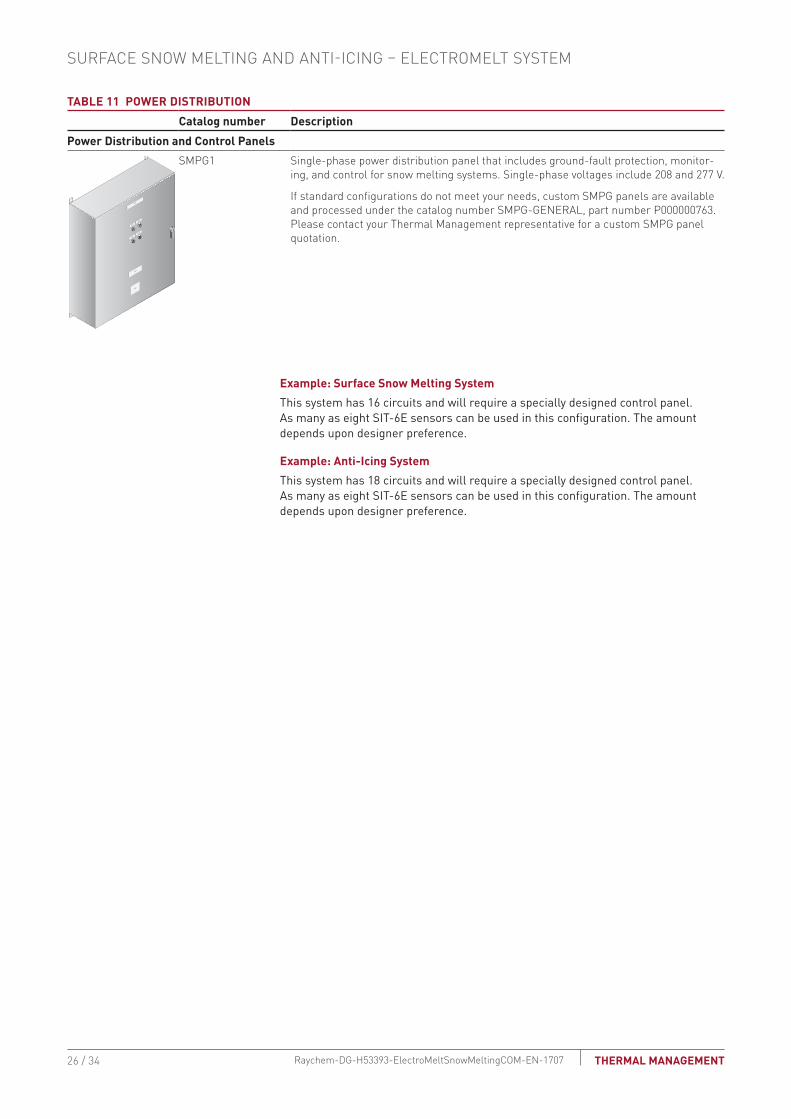
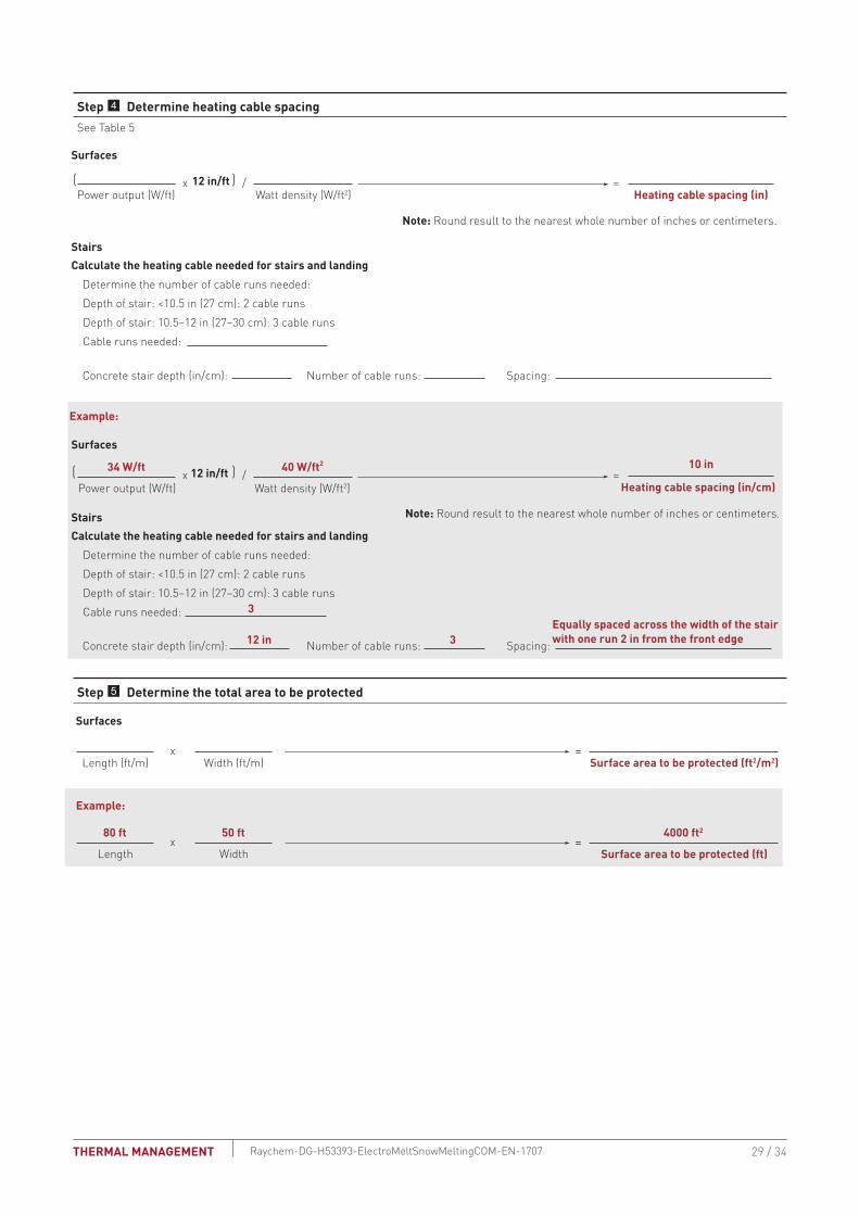
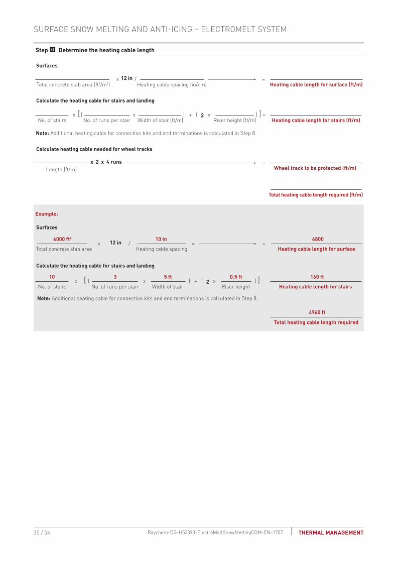
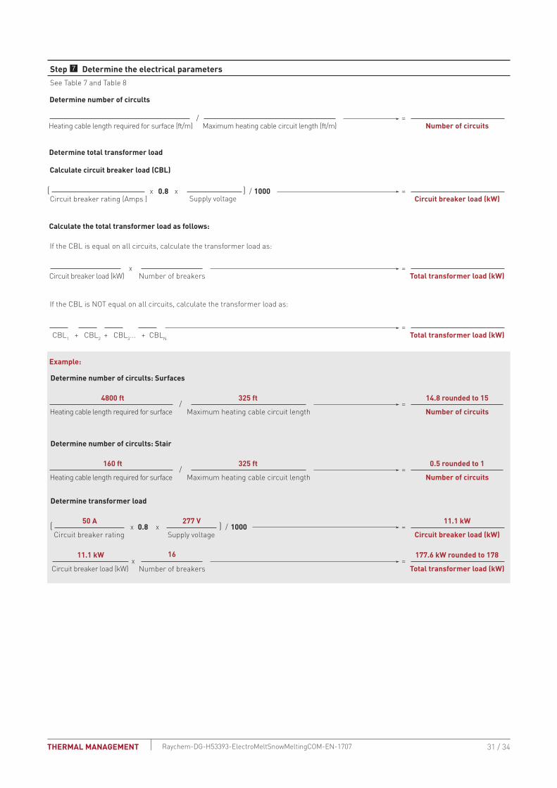
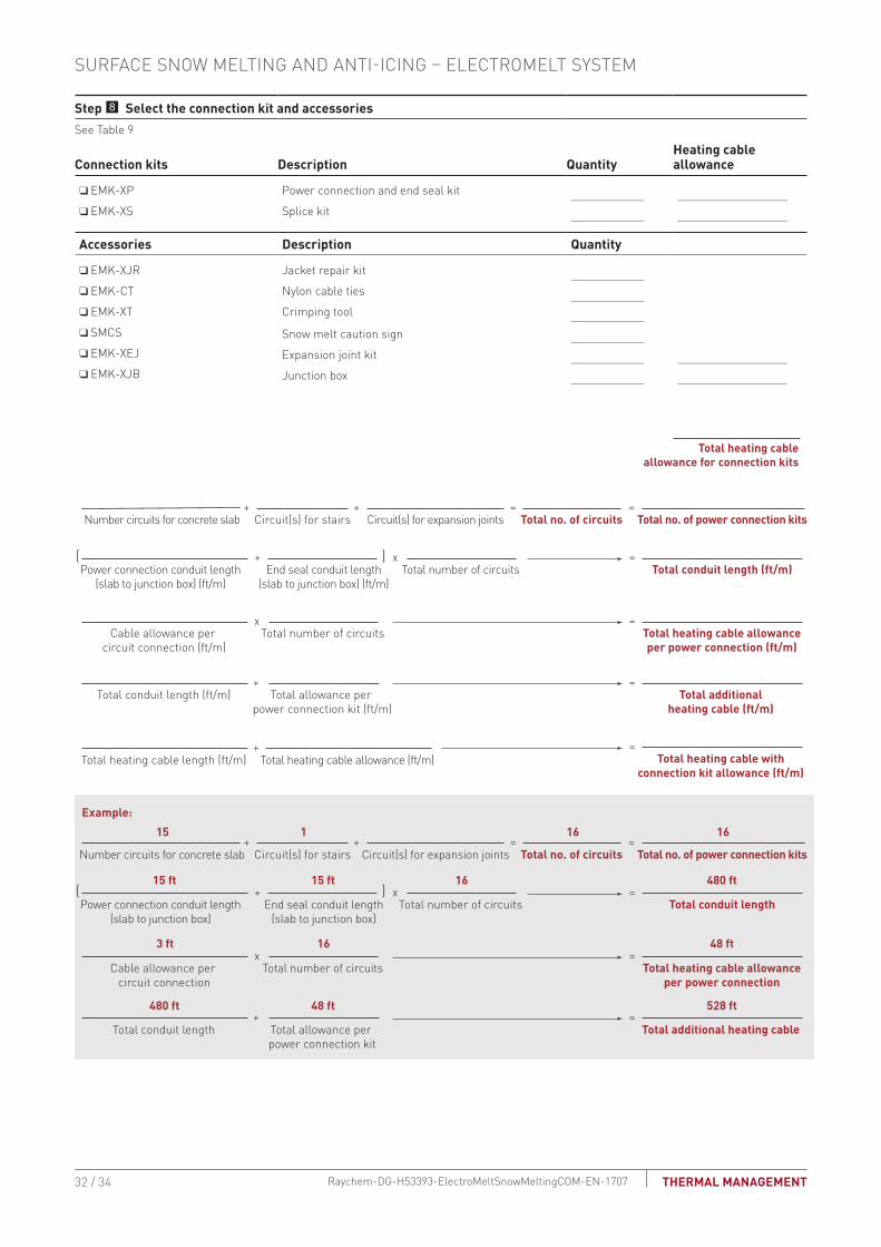