Asphalt application. Ice & Snow Melting - Danfoss€¦ · Application manual Asphalt application....
16
Application manual Asphalt application. Ice & Snow Melting Intelligent solutions with lasting effect Visit devi.com Asphalt application. Ice & Snow Melting
Transcript of Asphalt application. Ice & Snow Melting - Danfoss€¦ · Application manual Asphalt application....
Application manual
Asphalt application.Ice & Snow Melting
Intelligent solutions with lasting effect
Visit devi.com
Asphalt application. Ice & Snow Melting
Let DEVI do the work
DEVI - an abbreviation of Dansk El-Varme Industri – was established in Copenhagen, Denmark, in 1942. As from January 1st 2003 DEVI has become a part of the Danfoss Group - Denmark’s largest industrial Group. Danfoss is one of the world’s leading companies within heating, cooling and air-conditioning. The Danfoss Group has more than 23.000 employees and serves customers in more than 100 countries.
DEVI is Europe’s leading brand of electrical cable heating systems and electric pipe heating systems with over 70 years of experience. The production of heating cables takes place in France and Poland while the head office is situated in Denmark.
The value of experience We have installed literally thousands of systems across the globe, in every conceivable setting. This experience means that we can offer you practical advice about precisely which components you need to get the best results at the lowest cost.
Asphalt application. Ice & Snow MeltingThis design guide presents DEVI’s recommendations for design and installation of ice and snow melting systems for asphalt application. It provides guidance for heating cable positioning, electrical data and system configurations.
Following DEVI’s recommendations will ensure energy efficient, reliable and maintenance free solution for constant wattage heating cables with 20 year warranty.
Index
1. Application Briefing 4
2. System Description 5
3. Products 7
4. System Design 9
5. Installation 12
6. Cases 16
Our quality management system and compliances
Along with full compliance with EU
directives and product approvals
ISO 9001 TS 16949
ISO 14001 PED
1. Application Briefing
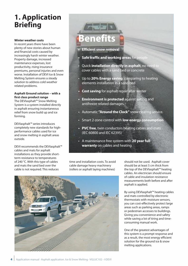
Winter weather costs In recent years there have been plenty of new stories about human and financial costs caused by increasingly harsh winter weather. Property damage, increased maintenance expenses, lost productivity, rising insurance premiums, personal injuries and even worse. Installation of DEVI Ice & Snow Melting System ensures a steady solution to address cold weather related problems.
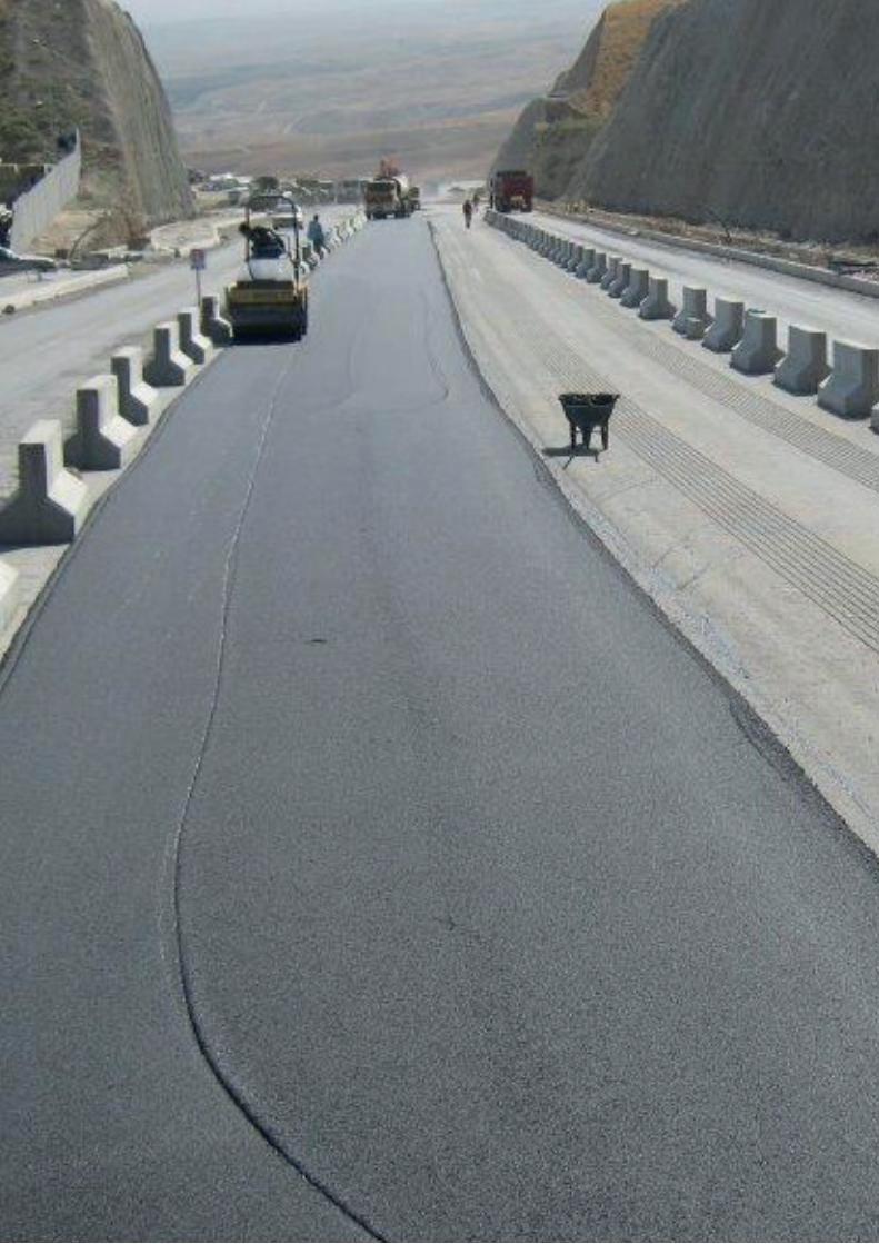
Asphalt Ground solution – with a first class product range The DEVIasphalt™ Snow Melting System is a system installed directly in asphalt ensuring instantaneous relief from snow build up and ice forming.
DEVIasphalt™ series introduces completely new standards for high-performance cables used for ice and snow melting in asphalt areas outside.
DEVI recommends the DEVIasphalt™ cables and mats for asphalt installations as they provide short-term resistance to temperatures of 240 °C. With this type of cables and mats the sand bed over the cable is not required. This reduces
time and installation costs. To avoid cable damage heavy machinery (rollers or asphalt laying machines)
should not be used. Asphalt cover should be at least 5 cm thick from the top of the DEVIasphalt™ heating cables. An electrician should ensure of cable and insulation resistance measurements both before and after asphalt is applied.
By using DEVIasphalt™ heating cables and mats controlled by electronic thermostats with moisture sensors, you can cost-effectively protect large areas such as parking areas, ramps or pedestrian accesses to buildings. Giving you convenience and safety while saving a lot of tiring and time-consuming manual work.
One of the greatest advantages of this system is a prompt response and as a result, the most energy efficient solution for the ground ice & snow melting applications.
Benefits• Efficient snow removal
• Safe traffic and working areas for people
• Quick installation directly in asphalt, no need to cover cables with a sand bed or concrete
• Up to 20% Energy saving comparing to heating elements installation in a sand bed
• Cost saving for asphalt repair after winter
• Environment is protected against salting and antifreeze related damages.
• Automatic ”Around the Clock” snow clearing service.
• Smart 2-zone control with low energy consumption
• PVC free, twin conductors heating cables and mats (IEC 60800 and IEC 62395)
• A maintenance free system with 20 year full warranty on cables and heating
4 Application manual · Asphalt application. Ice & Snow Melting · VGLUC102 · ©DEVI
2. System Description
The most common DEVI ice and snow melting applications on ground are car parks, driveways, pavements, outdoor steps, loading platforms and bridges.
Main purpose of the application is to melt snow or slippery ice on asphalt surfaces.
Like for any other outdoor areas during winter, snow and ice needs to be removed from asphalt surfaces to secure safe access to buildings. It can be done manually or in a smart way – by means of electrical ice & snow melting system with thermostat control and moisture and temperature sensors that can control 2 zones simultaneously. Inactive during cold but dry weather 2 zone control saves energy and reduces costs.
The automatic regulation of the snow melting system keeps areas free of snow and passable at all times – night and day.
Another great advantage of the system installed directly in asphalt is a prompt response or warm up time compared to other installations.
Two types of asphalt applications are used most frequently: Mastic asphalt and Road/concrete asphalt.
Important: if DEVIasphalt™ cable or mat is embedded in asphalt• 2 layers of asphalt must be always
ensured• DEVIasphalt™ cable must be
installed in the first asphalt layer (max. 8 mm stone fraction)
• If road asphalt is used, first layer must be rolled by a hand drum
• First layer must be cooled down to max 80 °C before laying the second layer
• The second layer can be rolled with up to 500 kg
When installing ice and snow melting systems on steep slopes it may be necessary to provide some drainage for melted water at the slope bottom. The drain system should also be protected against ice formations.
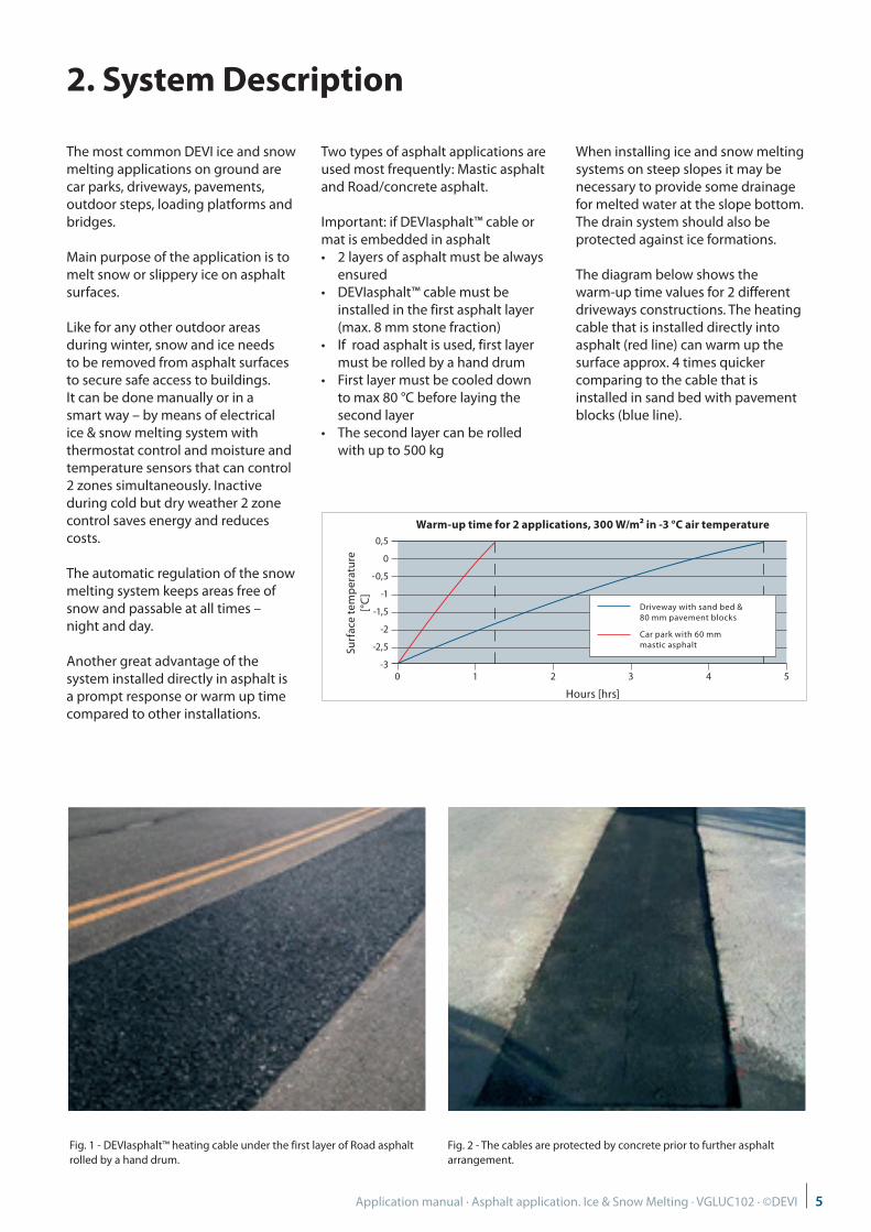
The diagram below shows the warm-up time values for 2 different driveways constructions. The heating cable that is installed directly into asphalt (red line) can warm up the surface approx. 4 times quicker comparing to the cable that is installed in sand bed with pavement blocks (blue line).
0,5
0
-0,5
-1
-1,5
-2
-2,5
-30 1 2 3 4 5
Hours [hrs]
Surf
ace
tem
per
atur
e[°
C]
Warm-up time for 2 applications, 300 W/m² in -3 °C air temperature
Driveway with sand bed & 80 mm pavement blocks
Car park with 60 mm mastic asphalt
Fig. 1 - DEVIasphalt™ heating cable under the first layer of Road asphalt rolled by a hand drum.
Fig. 2 - The cables are protected by concrete prior to further asphalt arrangement.
5Application manual · Asphalt application. Ice & Snow Melting · VGLUC102 · ©DEVI
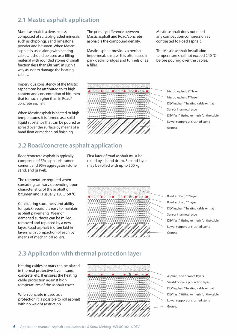
2.3 Application with thermal protection layer
Heating cables or mats can be placed in thermal protective layer – sand, concrete, etc. It ensures the heating cable protection against high temperatures of the asphalt cover.
When concrete is used as a protection it is possible to roll asphalt with no weight restriction.
2.2 Road/concrete asphalt application
Road/concrete asphalt is typically composed of 5% asphalt/bitumen cement and 95% aggregates (stone, sand, and gravel).
The temperature required when spreading can vary depending upon characteristics of the asphalt or bitumen and is usually 130...150 °C.
Considering sturdiness and ability for quick repair, it is easy to maintain asphalt pavements. Wear or damaged surfaces can be milled, removed and replaced by a new layer. Road asphalt is often laid in layers with compaction of each by means of mechanical rollers.
First later of road asphalt must be rolled by a hand drum. Second layer may be rolled with up to 500 kg.
Road asphalt, 2nd layer
Road asphalt, 1st layer
DEVIasphalt™ heating cable or mat
Sensor in a metal pipe
DEVIfast™ fitting or mesh for the cable
Lower support or crushed stone
Ground
Asphalt, one or more layers
Sand/Concrete protection layer
DEVIasphalt™ heating cable or mat
DEVIfast™ fitting or mesh for the cable
Lower support or crushed stone
Ground
2.1 Mastic asphalt application
Mastic asphalt is a dense mass composed of suitably graded minerals such as chippings, sand, limestone powder and bitumen. When Mastic asphalt is used along with heating cables, it should be used as a filling material with rounded stones of small fraction (less than Ø8 mm) in such a way as not to damage the heating cables.
Impervious consistency of the Mastic asphalt can be attributed to its high content and concentration of bitumen that is much higher than in Road/concrete asphalt.
When Mastic asphalt is heated to high temperatures, it is formed as a solid liquid substance that can be poured or spread over the surface by means of a hand float or mechanical finishing.
The primary difference between Mastic asphalt and Road/concrete asphalt is the compound density.
Mastic asphalt provides a perfect impermeable mass. It is often used in park decks, bridges and tunnels or as a filler.
Mastic asphalt does not need any compaction/compression as contrasted to Road asphalt.
The Mastic asphalt installation temperature shall not exceed 240 °C before pouring over the cables.
Mastic asphalt, 2nd layer
Mastic asphalt, 1st layer
DEVIasphalt™ heating cable or mat
Sensor in a metal pipe
DEVIfast™ fitting or mesh for the cable
Lower support or crushed stone
Ground
6 Application manual · Asphalt application. Ice & Snow Melting · VGLUC102 · ©DEVI
3. Products
Heating elements
For a heating system installed into asphalt following resistive (constant wattage) heating elements can be used:
• DEVIasphalt™ 30T heating cable;• DEVIasphalt™ 300T heating mat.
DEVI resistive heating cables ensure safe, efficient and economical asphalt application.
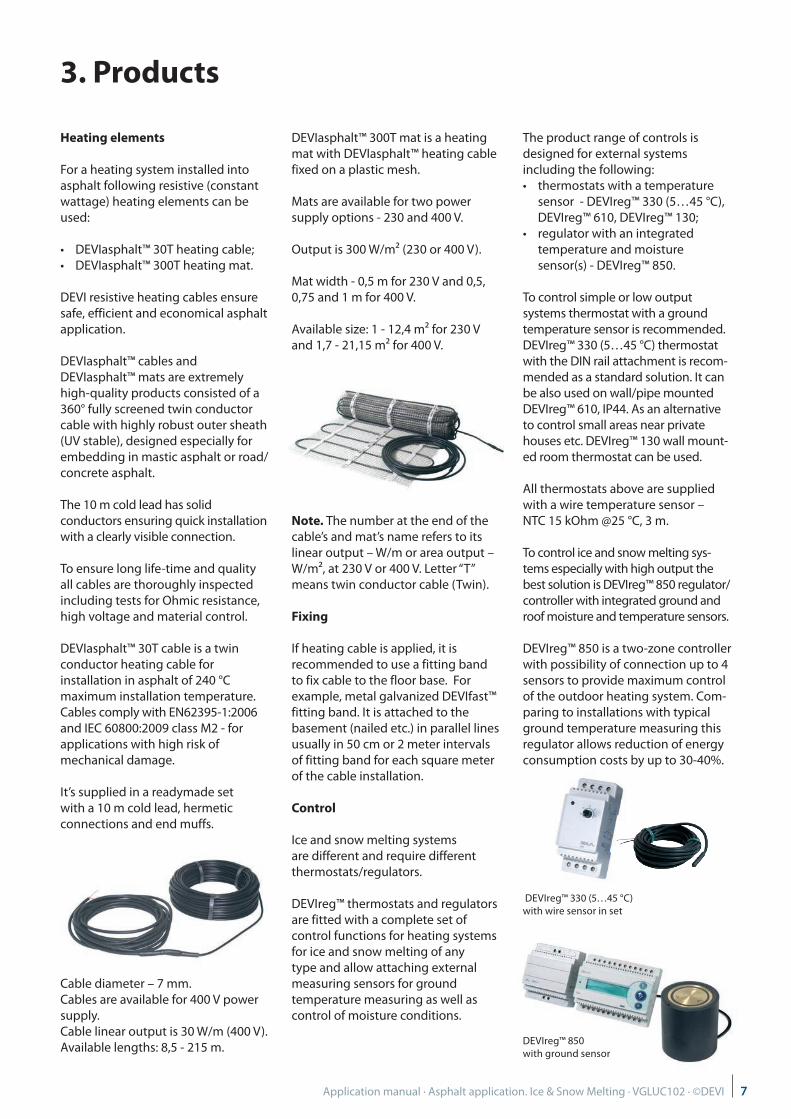
DEVIasphalt™ cables and DEVIasphalt™ mats are extremely high-quality products consisted of a 360° fully screened twin conductor cable with highly robust outer sheath (UV stable), designed especially for embedding in mastic asphalt or road/concrete asphalt.
The 10 m cold lead has solid conductors ensuring quick installation with a clearly visible connection.
To ensure long life-time and quality all cables are thoroughly inspected including tests for Ohmic resistance, high voltage and material control.
DEVIasphalt™ 30T cable is a twin conductor heating cable for installation in asphalt of 240 °C maximum installation temperature. Cables comply with EN62395-1:2006 and IEC 60800:2009 class M2 - for applications with high risk of mechanical damage.
It’s supplied in a readymade set with a 10 m cold lead, hermetic connections and end muffs.
Cable diameter – 7 mm. Cables are available for 400 V power supply. Cable linear output is 30 W/m (400 V). Available lengths: 8,5 - 215 m.
DEVIasphalt™ 300T mat is a heating mat with DEVIasphalt™ heating cable fixed on a plastic mesh.
Mats are available for two power supply options - 230 and 400 V.
Output is 300 W/m² (230 or 400 V).
Mat width - 0,5 m for 230 V and 0,5, 0,75 and 1 m for 400 V.
Available size: 1 - 12,4 m² for 230 V and 1,7 - 21,15 m² for 400 V.
Note. The number at the end of the cable’s and mat’s name refers to its linear output – W/m or area output – W/m², at 230 V or 400 V. Letter “T” means twin conductor cable (Twin).
Fixing
If heating cable is applied, it is recommended to use a fitting band to fix cable to the floor base. For example, metal galvanized DEVIfast™ fitting band. It is attached to the basement (nailed etc.) in parallel lines usually in 50 cm or 2 meter intervals of fitting band for each square meter of the cable installation.
Control
Ice and snow melting systems are different and require different thermostats/regulators.
DEVIreg™ thermostats and regulators are fitted with a complete set of control functions for heating systems for ice and snow melting of anytype and allow attaching external measuring sensors for ground temperature measuring as well as control of moisture conditions.
The product range of controls is designed for external systems including the following: • thermostats with a temperature
sensor - DEVIreg™ 330 (5…45 °C), DEVIreg™ 610, DEVIreg™ 130;
• regulator with an integrated temperature and moisture sensor(s) - DEVIreg™ 850.
To control simple or low output systems thermostat with a ground temperature sensor is recommended. DEVIreg™ 330 (5…45 °C) thermostat with the DIN rail attachment is recom-mended as a standard solution. It can be also used on wall/pipe mounted DEVIreg™ 610, IP44. As an alternative to control small areas near private houses etc. DEVIreg™ 130 wall mount-ed room thermostat can be used.
All thermostats above are supplied with a wire temperature sensor – NTC 15 kOhm @25 °C, 3 m.
To control ice and snow melting sys-tems especially with high output the best solution is DEVIreg™ 850 regulator/controller with integrated ground and roof moisture and temperature sensors.
DEVIreg™ 850 is a two-zone controller with possibility of connection up to 4 sensors to provide maximum control of the outdoor heating system. Com-paring to installations with typical ground temperature measuring this regulator allows reduction of energy consumption costs by up to 30-40%.
DEVIreg™ 330 (5…45 °C) with wire sensor in set
DEVIreg™ 850 with ground sensor
7Application manual · Asphalt application. Ice & Snow Melting · VGLUC102 · ©DEVI
Products - general overview for ice and snow melting for Asphalt application
Product Options Description
DEVIasphalt™Resistive heating cable
DEVIasphalt™ 30T 400 V program
Twin conductor, 100% screen, UV stabilized, black, short term contact with 240 °C allowed, 30 W/m (400 V).DIN IEC 60800:2009 M2, EN 62395-1:2006
DEVIasphalt™Resistive heating mat
DEVIasphalt™ 300T 230 & 400 V program
Twin conductor, 100% screen, UV stabilized, black, short term contact with 240 °C allowed, 300 W/m² (230 V/400 V).DIN IEC 60800:2009 M2, EN 62395-1:2006
Fixing DEVIfast™ Metal 25 m pack; galvanized metal, fixings every 2,5 cm.
DEVIreg™Regulator
DEVIreg™ 850Connection to Ground and Roof moisture and temp. sensor, max 4 sensors, 2 zones, 2x15 A, PSU 24 V, DIN rail
Moisture & temperature sensor
Ground sensor for DEVIreg™ 850
Ø93 x 98 mm, IP67, 15 m connection cable 4x1 mm²
AccessoriesPSU 24 V for DEVIreg™ 850
Extra PSU for DEVIreg™ 850 with 3-4 sensors
DEVIreg™Thermostat
DEVIreg™ 330 (5…45 °C)5…45 °C, 16 A, IP20, with wire sensor, 3 m,DIN rail
DEVIreg™Thermostat
DEVIreg™ 610 -30…+50 °C, 10 A, IP44, with wire sensor, 3 m,on wall/pipe installation
DEVIreg™Room thermostat
DEVIreg™ 130 5…45 °C, 16 A, IP30, with wire sensor, 3 m,room on wall installation
Temperature sensor 10 m, PVC Wire sensor, Ø8 mm, IP65, NTC 15 kOhm @25 °C
For additional information please refer to the DEVI Catalogue.
8 Application manual · Asphalt application. Ice & Snow Melting · VGLUC102 · ©DEVI

4. System Design
The following paragraphs contain estimations according to ASHRAE, Application Handbook and Historical Weather Data.
Figures are for reference only and can vary depending on the area size, wind speed and ground construction.
Installed output (in W/m²) for asphalt areas is identical to other ice & snow melting installations. For more information about performance of ice and snow melting systems, as well as control, see Outdoor Application manuals.
When installing ice and snow melting systems it may be necessary to provide drainage for melted water at the slope bottom, walkways, etc. The drain system should also be protected against ice formations.
4.1 Output
The heat required for snow melting depends on the following main factors:
• Weather data (min temperature, max. snowfall rate, wind speed, humidity, altitude);
• Project details (materials, foundation type, dimensions, insulation);
• Electrical data (voltage, power, control requirements);
• System performance expectations;• Safety factor.
Evaluation of the specific output for ice and snow melting systems can be done based on the diagram and other similar documents.
For example, heat loss depending on the wind speed and temperature differences between the surface and the ambient air is described in 2003 ASHRAE Application Handbook (see fig. 3).
For example, for medium weather conditions and 6 m/s wind speed, if choosing ΔT = 10 K (from -3 K to +7 K) the heat loss value is approx. 230 W/m² (marked with the red dotted line in fig. 3).
In other words, surface heating up to 10 degrees requires 230 W/m² or 230 / 10 = 23 W/(m²·K).
All in all, for medium winter weather conditions, heating of 1 m² outdoor surface up to 1°С needs power of approx. 23 Watts. Or the calculation heat exchange coefficient for outdoor surfaces is approx. 23 W/(m²·K) (sometimes named αout – “alpha out”).
As an example IEC 62395-2 provides another evaluation of typical snow melting heat loads (see table 1).
Values in table 1 less than 250 W/m² should be used in limited circumstances, for example in countries with warm climate or with the technical justification. Low output at the level of 150-200 W/m² may lack for snow and ice melting.
For ice and snow melting systems should be recommended next outputs:• minimum– 250 W/m²,• optimum – 350 W/m².
Output for ice and snow melting systems should be designed to follow the local norms and regulations.
Add 100 W/m²:• for every 1000 m altitude;• if the heated area isafree standing
construction without insulation;• if the local average wind speed is• >6 m/s;• if the more efficient system is
required;• if it snows at temperatures lower
than -10 °C.
Note. It can be recommended to design output for ice and snow melting systems with maximum possible level.
-3 -1 1 3 5 7 9 11 13 15 17 19 21 23 250
100
200
300
400
500
600
700
0 m/s
2 m/s
4 m/s
6 m/s
8 m/s
10 m/s
15 m/s
20 m/s
25 m/s
30 m/s
Weather severity
Application criticality
Minimum, for example, residential walkways and
driveways
Moderate, for example, commercial walkways and
driveways
Maximum, for example, tall plazas, hospital emergency
entrances and helicopter decks
W/m²
Mild 150 to 250 250 to 350 300 to 400
Severe 200 to 300 300 to 400 350 to 500
Very severe 250 to 350 400 to 550 450 to 750
No back loss & area width 6 m & 50% cloud cover Surface temp. - 3 °C & 70% relative humidity
Temperature difference [K] between surface and ambience
Hea
tlos
s [W
/m²]
Fig. 3. Wind and temperature dependent heat loss
Table 1. IEC62395-2. Typical snow melting heat loads
9Application manual · Asphalt application. Ice & Snow Melting · VGLUC102 · ©DEVI

Minimum melting temperature
The main task of ice and snow melting systems is melting, i.e. to maintain +3 °C on the surface. Any output can be addressed to the lowest temperature at which ice and snow is still melting or the heating system will cope with its main task. Table 2 shows some heat outputs (W/m²) and temperatures at which system ensures ice & snow melting or, in other words, supports +3 °С on the surface.
For example, if 250 W/m² is installed, then the heating system enables ice and snow melting at the air temperature not lower than -8 °C (ΔT = 250/23 ≈ 11 °C). But if the ambient/air temperature is -12 °C for instance, then the surface temperature will be -1 °C, with ΔT = -11 °C for output of 250 W/m². It means that the system consumes power for surface heating, but doesn’t melt ice and snow at all.
4.2 Insulation
The benefit of thermal insulation is significant for free standing constructions as ramps or bridges, steps, etc. Insulation of the free sides of the construction must also be considered.
In this example, a 6 m wide bridge is exposed to snow at -3 °C air temperature and 4,5 m/s crossing wind. Calculated approx. downward heat losses are presented in the table below.
Insulation thickness
Downward heat loss, %
No insulation 36
20 mm 23
50 mm 15
100 mm 9
4.3 C-C distance and corresponding output (W/m²)The C-C distance is the centre- to-centre distance between theadjacent cables (sometimes named “installation step”).
С-С
С-С
Note! Heating cable bending diameter must be at least 6 times cable diameter.
TThe C-C distance and corresponding output W/m² can be calculated by the following formulas (see also Application manual - Cable Floor Heating Systems):
or
Output of the DEVIasphalt™ cable for some C-C is presented in table:
C-C distance, cm
Heat density, W/m² (400 V)
DEVIasphalt™ 30T
5 600
6 500
7 429
7.5 400
8 375
9 333
10 300
Table 2. Minimum melting air temperatures for some outputs. ΔT surface-air is calculated as output divided by the heat exchange coefficient 23 W/(m²·K).
Asphalt, one or more layers
Sand or concrete protection layer
DEVIasphalt™ heating cable
DEVIfast™ fitting or mesh for the cable
Insulation
Free standing construction
Ambient/air temperature
C - C [cm] = Area [m²] · 100 cm Cable length [m]
C - C [cm] = Cable output [W/m] · 100 cm
Heat density [W/m²]
Output,W/m²
Min air temperature for +3 °C on surface
(αout
= 23 W/(m²·K))
250 -8 °C
300 -10 °C
350 -12 °C
400 -14 °C
550 -21 °C
10 Application manual · Asphalt application. Ice & Snow Melting · VGLUC102 · ©DEVI
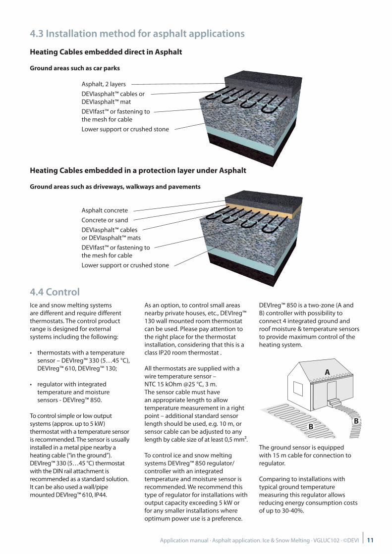
Heating Cables embedded in a protection layer under Asphalt
Ground areas such as driveways, walkways and pavements
4.3 Installation method for asphalt applications
Heating Cables embedded direct in Asphalt
Ground areas such as car parks
4.4 ControlIce and snow melting systems are different and require different thermostats. The control product range is designed for external systems including the following:
• thermostats with a temperature sensor – DEVIreg™ 330 (5…45 °C), DEVIreg™ 610, DEVIreg™ 130;
• regulator with integrated temperature and moisture sensors - DEVIreg™ 850.
To control simple or low output systems (approx. up to 5 kW) thermostat with a temperature sensor is recommended. The sensor is usually installed in a metal pipe nearby a heating cable (“in the ground”). DEVIreg™ 330 (5…45 °C) thermostat with the DIN rail attachment is recommended as a standard solution. It can be also used a wall/pipe mounted DEVIreg™ 610, IP44.
As an option, to control small areas nearby private houses, etc., DEVIreg™ 130 wall mounted room thermostat can be used. Please pay attention to the right place for the thermostat installation, considering that this is a class IP20 room thermostat .
All thermostats are supplied with a wire temperature sensor – NTC 15 kOhm @25 °C, 3 m. The sensor cable must have an appropriate length to allow temperature measurement in a right point – additional standard sensor length should be used, e.g. 10 m, or sensor cable can be adjusted to any length by cable size of at least 0,5 mm².
To control ice and snow melting systems DEVIreg™ 850 regulator/ controller with an integrated temperature and moisture sensor is recommended. We recommend this type of regulator for installations with output capacity exceeding 5 kW or for any smaller installations where optimum power use is a preference.
DEVIreg™ 850 is a two-zone (A and B) controller with possibility to connect 4 integrated ground and roof moisture & temperature sensors to provide maximum control of the heating system.
The ground sensor is equipped with 15 m cable for connection to regulator.
Comparing to installations with typical ground temperature measuring this regulator allows reducing energy consumption costs of up to 30-40%.
A
BB
Asphalt, 2 layers
DEVIasphalt™ cables or DEVIasphalt™ mat
DEVIfast™ or fastening to the mesh for cable
Lower support or crushed stone
Asphalt concrete
Concrete or sand
DEVIasphalt™ cables or DEVIasphalt™ mats
DEVIfast™ or fastening to the mesh for cable
Lower support or crushed stone
11Application manual · Asphalt application. Ice & Snow Melting · VGLUC102 · ©DEVI

5. Installation
5.1 General safety instructions
Never cut or shorten the heating element.
• Cutting the heating element will void the warranty.
• Cold leads can be shortened to suit requirements.
Elements must always be installed according to local building regulations and wiring rules as well as the guidelines in proper installation instructions and this manual.
• Any other installation may hamper element functionality or constitute a safety risk, and will void the warranty.
• Make sure that elements, cold leads, connection boxes, and other electrical components do not come into contact with chemicals or flammable materials during or after installation.
!
Elements must always be connected by an authorized electrician using a fixed connection.
• De-energize all power circuits before installation and service.
• The connection to the power source must not be directly accessible to the end user.
• Each heating cable screen must be earthed in accordance with local electricity regulations and connected to a residual current device (RCD).
• Recommended RCD trip rating is 30 mA, but may be up to 300 mA where capacitive leakage may lead to nuisance tripping.
• Heating elements must be connected via a switch providing all pole disconnection.
• The element must be equipped with a correctly sized fuse or circuit breaker, e.g. 10/13 A for a 1,5 mm² cold lead and 16/20 A for a 2,5 mm² cold lead.
The presence of a heating element must• be made evident by affixing
caution signs or markings at the power connection fittings and/or frequently along the circuit line where clearly visible
• be stated in any electrical documentation following the installation.
Never exceed the maximum heat density (W/m² or W/m) for the actual application.
1. Fuse2. RCD3. All-pole switch4. Thermostat5. Conduit pipe6. Sensor7. Connection muff8. Cable screen9. Heating cable
TS
T
RCDI≤30 mA
9
4
65
87
2
3
1
12 Application manual · Asphalt application. Ice & Snow Melting · VGLUC102 · ©DEVI
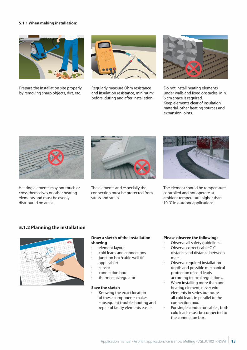
5.1.1 When making installation:
Prepare the installation site properly by removing sharp objects, dirt, etc.
Regularly measure Ohm resistance and insulation resistance, minimum: before, during and after installation.
Do not install heating elements under walls and fixed obstacles. Min. 6 cm space is required. Keep elements clear of insulation material, other heating sources and expansion joints.
Heating elements may not touch or cross themselves or other heating elements and must be evenly distributed on areas.
The elements and especially the connection must be protected from stress and strain.
The element should be temperature controlled and not operate at ambient temperature higher than 10 °C in outdoor applications.
5.1.2 Planning the installation
Draw a sketch of the installation showing• element layout• cold leads and connections• junction box/cable well (if
applicable)• sensor• connection box• thermostat/regulator
Save the sketch• Knowing the exact location
of these components makes subsequent troubleshooting and repair of faulty elements easier.
Please observe the following:• Observe all safety guidelines.• Observe correct cable C-C
distance and distance between mats.
• Observe required installation depth and possible mechanical protection of cold leads according to local regulations.
• When installing more than one heating element, never wire elements in series but route all cold leads in parallel to the connection box.
• For single conductor cables, both cold leads must be connected to the connection box.
13Application manual · Asphalt application. Ice & Snow Melting · VGLUC102 · ©DEVI
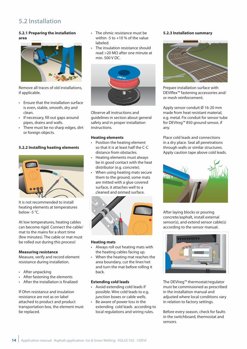
5.2 Installation
5.2.1 Preparing the installation area
Remove all traces of old installations, if applicable.
• Ensure that the installation surface is even, stable, smooth, dry and clean.
• If necessary, fill out gaps around pipes, drains and walls.
• There must be no sharp edges, dirt or foreign objects.
5.2.2 Installing heating elements
It is not recommended to install heating elements at temperatures below -5 °C.
At low temperatures, heating cables can become rigid. Connect the cable/mat to the mains for a short time (few minutes). The cable or mat must be rolled out during this process!
Measuring resistanceMeasure, verify and record element resistance during installation.
• After unpacking• After fastening the elements• After the installation is finalized
If Ohm resistance and insulation resistance are not as on label attached to product and product transportation box, the element must be replaced.
• The ohmic resistance must be within -5 to +10 % of the value labeled.
• The insulation resistance should read >20 MΩ after one minute at min. 500 V DC.
Observe all instructions and guidelines in section about general safety and in proper installation instructions.
Heating elements• Position the heating element
so that it is at least half the C-C distance from obstacles.
• Heating elements must always be in good contact with the heat distributor (e.g. concrete).
• When using heating mats secure them to the ground, some mats are mitted with a glue covered surface, it attaches well to a cleaned and primed surface.
Heating mats• Always roll out heating mats with
the heating cables facing up.• When the heating mat reaches the
area boundary, cut the liner/net and turn the mat before rolling it back.
Extending cold leads• Avoid extending cold leads if
possible. Wire cold leads to e.g. junction boxes or cable wells.
• Be aware of power loss in the extending cold leads according to local regulations and wiring rules.
5.2.3 Installation summary
Prepare installation surface with DEVIflex™ fastening accessories and/or mesh reinforcement.
Apply sensor conduit Ø 16-20 mm made from heat resistant material, e.g. metal. Fix conduit for sensor tube for DEVIreg™ 850 ground sensor, if any. Place cold leads and connections in a dry place. Seal all penetrations through walls or similar structures. Apply caution tape above cold leads.
After laying blocks or pouring concrete/asphalt, install external sensor(s), and extend sensor cable(s) according to the sensor manual.
The DEVIreg™ thermostat/regulator must be commissioned as prescribed in the installation manual and adjusted where local conditions vary in relation to factory settings.
Before every season, check for faults in the switchboard, thermostat and sensors.
14 Application manual · Asphalt application. Ice & Snow Melting · VGLUC102 · ©DEVI
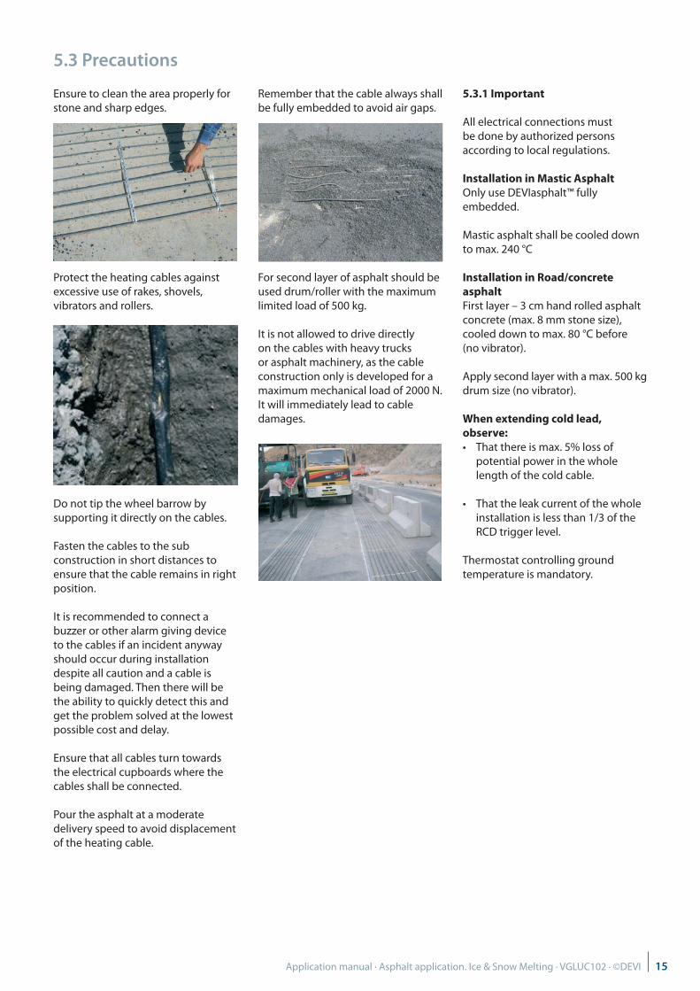
5.3 Precautions
Ensure to clean the area properly for stone and sharp edges.
Protect the heating cables against excessive use of rakes, shovels, vibrators and rollers.
Do not tip the wheel barrow by supporting it directly on the cables.
Fasten the cables to the sub construction in short distances to ensure that the cable remains in right position.
It is recommended to connect a buzzer or other alarm giving device to the cables if an incident anyway should occur during installation despite all caution and a cable is being damaged. Then there will be the ability to quickly detect this and get the problem solved at the lowest possible cost and delay.
Ensure that all cables turn towards the electrical cupboards where the cables shall be connected.
Pour the asphalt at a moderate delivery speed to avoid displacement of the heating cable.
Remember that the cable always shall be fully embedded to avoid air gaps.
For second layer of asphalt should be used drum/roller with the maximum limited load of 500 kg.
It is not allowed to drive directly on the cables with heavy trucks or asphalt machinery, as the cable construction only is developed for a maximum mechanical load of 2000 N. It will immediately lead to cable damages.
5.3.1 Important
All electrical connections must be done by authorized persons according to local regulations.
Installation in Mastic Asphalt Only use DEVIasphalt™ fully embedded.
Mastic asphalt shall be cooled down to max. 240 °C
Installation in Road/concrete asphalt First layer – 3 cm hand rolled asphalt concrete (max. 8 mm stone size), cooled down to max. 80 °C before (no vibrator).
Apply second layer with a max. 500 kg drum size (no vibrator).
When extending cold lead, observe:• That there is max. 5% loss of
potential power in the whole length of the cold cable.
• That the leak current of the whole installation is less than 1/3 of the RCD trigger level.
Thermostat controlling ground temperature is mandatory.
15Application manual · Asphalt application. Ice & Snow Melting · VGLUC102 · ©DEVI
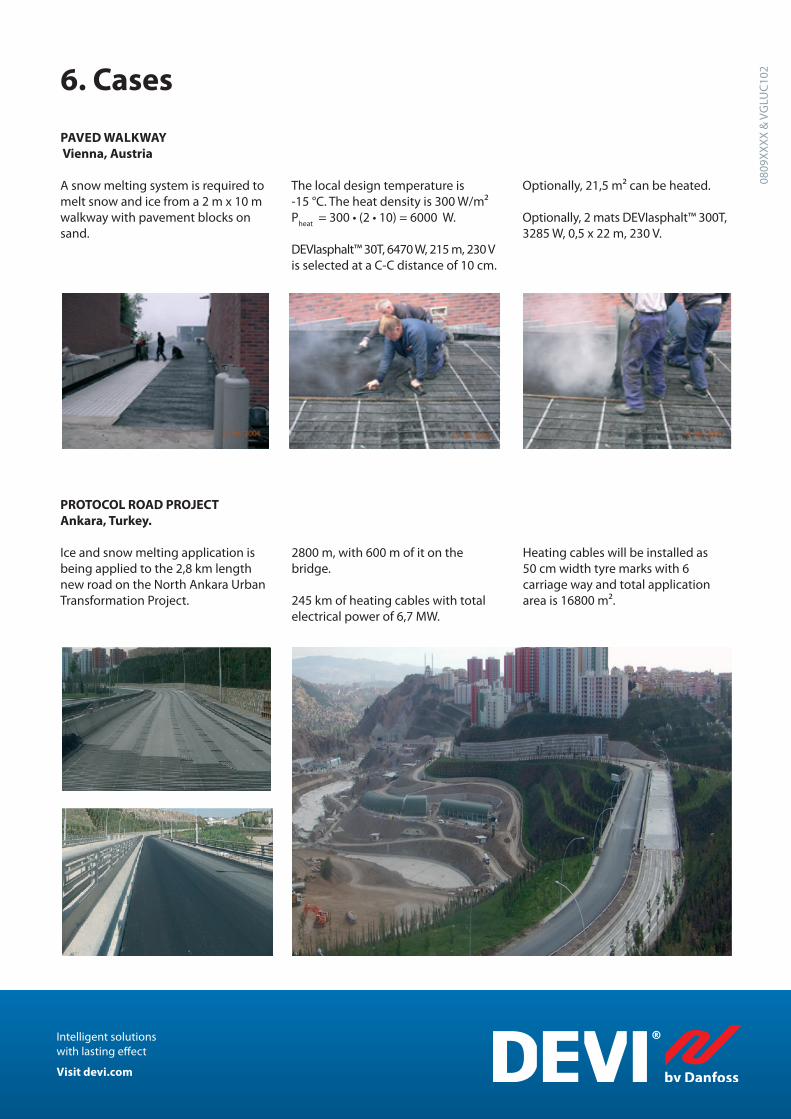
PROTOCOL ROAD PROJECT Ankara, Turkey.
6. Cases
PAVED WALKWAY Vienna, Austria
Intelligent solutions with lasting effect
Visit devi.com
A snow melting system is required to melt snow and ice from a 2 m x 10 m walkway with pavement blocks on sand.
The local design temperature is -15 °C. The heat density is 300 W/m² P
heat = 300 • (2 • 10) = 6000 W.
DEVIasphalt™ 30T, 6470 W, 215 m, 230 V is selected at a C-C distance of 10 cm.
Optionally, 21,5 m² can be heated.
Optionally, 2 mats DEVIasphalt™ 300T, 3285 W, 0,5 x 22 m, 230 V.
Ice and snow melting application is being applied to the 2,8 km length new road on the North Ankara Urban Transformation Project.
2800 m, with 600 m of it on the bridge.
245 km of heating cables with total electrical power of 6,7 MW.
Heating cables will be installed as 50 cm width tyre marks with 6 carriage way and total application area is 16800 m².
0809
XX
XX
& V
GLU
C10
2