Ice and snow melting system brochure
11
Snow and ice melting system
description
https://www.uponor.co.uk/~/media/countryspecific/uk/download-centre/brochure/ice-and-snow-melting-system-brochure.pdf?version=1
Transcript of Ice and snow melting system brochure
Snow and ice melting system

2 3Uponor snow and ice melting system
All technical and legal information contained in this catalogue has been carefully compiled according to the best of our knowledge. We cannot be held liable for any errors as these cannot be fully excluded. The technical guideline, including all sections, is protected by copyright. All uses beyond those permitted under the copyright law are not allowed without the approval of Uponor. This applies particularly to reproduction, re-prints, processing, storage and processing in electronic systems, translations and microfi lming. The contents of the technical guideline are subject to change without notice.
Copyright 2010 Uponor
Table of contents
"Easily predictable snow removal costs with Uponor Snow and Ice melting system"
Uponor Snow and ice melting design principles ................................................ 4
The design .......................................................... 6
Adjustable system solution for different structures . .......................................................... 8
Installing Uponor heating pipes ...................... 11
Uponor industrial snow and ice melting system components ........................................... 12
Installation of Uponor industrial manifold .... 17 Mounting .......................................................... 17 Hydraulic balancing .......................................... 18 Startup and testing ........................................... 19
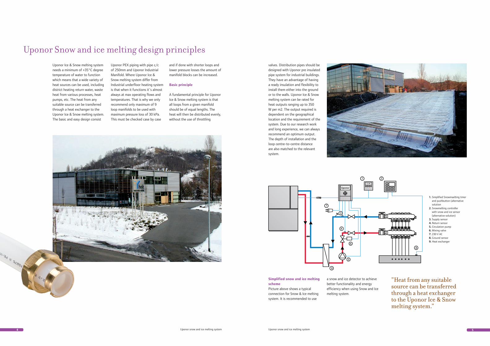
Uponor Ice & Snow melting system needs a minimum of +35°C degree temperature of water to function which means that a wide variety of heat sources can be used, including district heating return water, waste heat from various processes, heat pumps, etc. The heat from any suitable source can be transferred through a heat exchanger to the Uponor Ice & Snow melting system. The basic and easy design consist
4 5Uponor snow and ice melting system Uponor snow and ice melting system
Uponor Snow and ice melting design principlesUponor PEX piping with pipe c/c of 250mm and Uponor Industrial Manifold. Where Uponor Ice & Snow melting system differ from Industrial underfloor heating system is that when it functions it´s almost always at max operating flows and temperatures. That is why we only recommend only maximum of 9 loop manifolds to be used with maximum pressure loss of 30 kPa. This must be checked case by case
valves. Distribution pipes should be designed with Uponor pre insulated pipe system for industrial buildings. They have an advantage of having a ready insulation and flexibility to install them either into the ground or to the walls. Uponor Ice & Snow melting system can be rated for heat outputs ranging up to 350 W per m2. The output required is dependent on the geographical location and the requirement of the system. Due to our research work and long experience, we can always recommend an optimum output. The depth of installation and the loop centre-to-centre distance are also matched to the relevant system.
and if done with shorter loops and lower pressure losses the amount of manifold blocks can be increased.
Basic principle
A fundamental principle for Uponor Ice & Snow melting system is that all loops from a given manifold should be of equal lengths. The heat will then be distributed evenly, without the use of throttling
Simplified snow and ice melting schemePicture above shows a typical connection for Snow & Ice melting system. It is recommended to use
a snow and ice detector to achieve better functionality and energy efficiency when using Snow and Ice melting system.
"Heat from any suitable source can be transferred through a heat exchanger to the Uponor Ice & Snow melting system."
1. Simplified Snowmaelting timer and pushbutton (alternative solution2. Snowmelting controller with snow and ice sensor (alternative solution)3. Supply sensor 4. Return sensor5. Circulation pump6. Mixing valve7. 230 V AC8. Ground sensor9. Heat exchanger
7Uponor snow and ice melting system6 Uponor snow and ice melting system
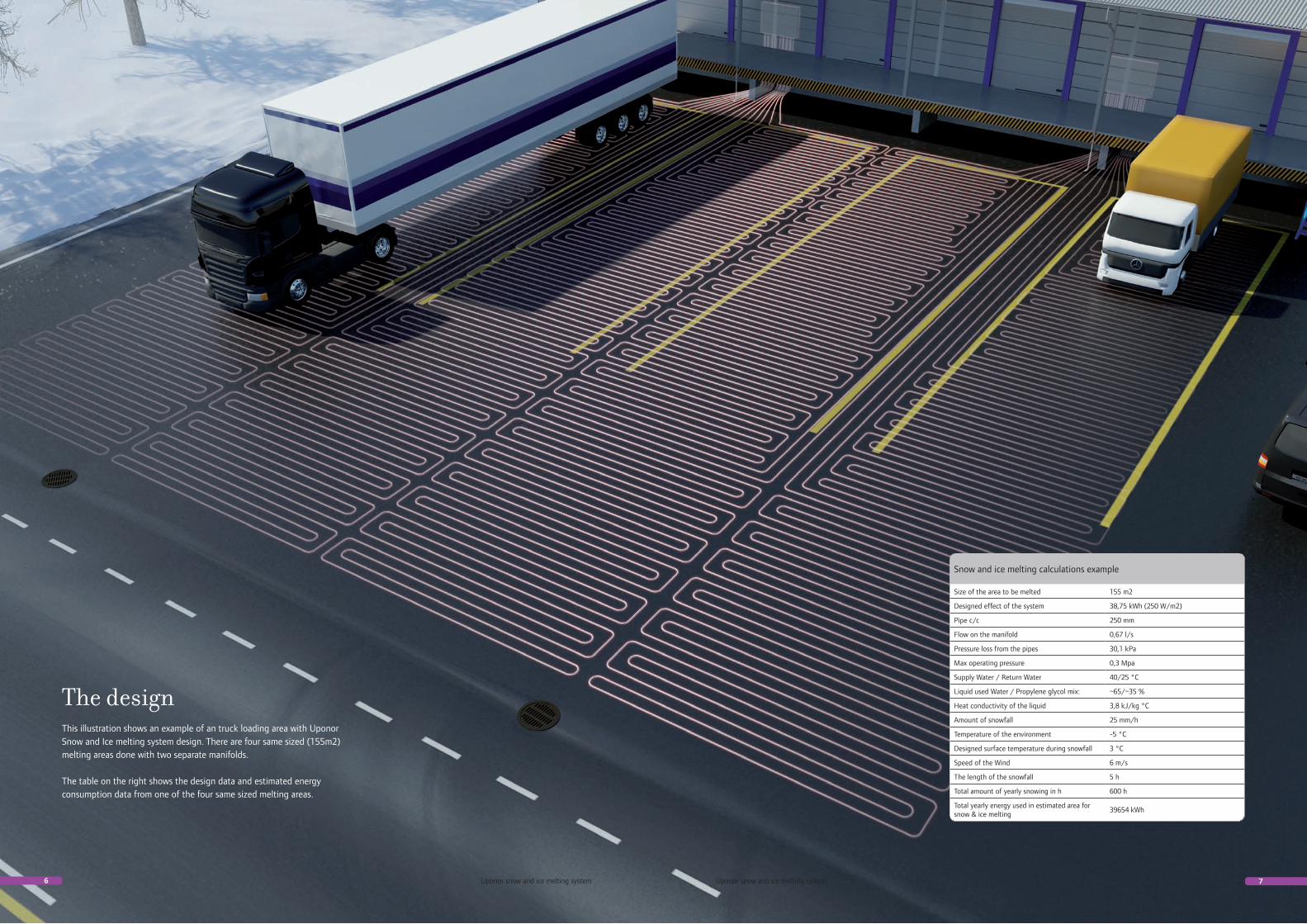
This illustration shows an example of an truck loading area with Uponor Snow and Ice melting system design. There are four same sized (155m2) melting areas done with two separate manifolds.
The table on the right shows the design data and estimated energy consumption data from one of the four same sized melting areas.
The design
Snow and ice melting calculations example
Size of the area to be melted 155 m2
Designed effect of the system 38,75 kWh (250 W/m2)
Pipe c/c 250 mm
Flow on the manifold 0,67 l/s
Pressure loss from the pipes 30,1 kPa
Max operating pressure 0,3 Mpa
Supply Water / Return Water 40/25 °C
Liquid used Water / Propylene glycol mix: ~65/~35 %
Heat conductivity of the liquid 3,8 kJ/kg °C
Amount of snowfall 25 mm/h
Temperature of the environment -5 °C
Designed surface temperature during snowfall 3 °C
Speed of the Wind 6 m/s
The length of the snowfall 5 h
Total amount of yearly snowing in h 600 h
Total yearly energy used in estimated area for snow & ice melting
39654 kWh
8 9Uponor snow and ice melting system Uponor snow and ice melting system
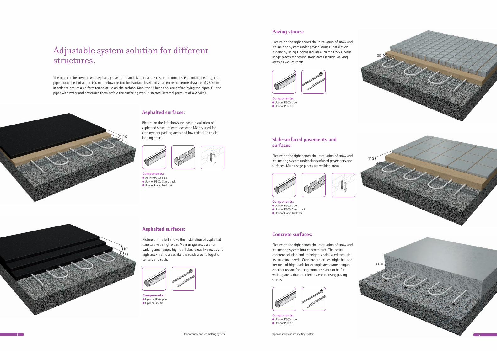
Asphalted surfaces:
Picture on the left shows the basic installation of asphalted structure with low wear. Mainly used for employment parking areas and low trafficked truck loading areas.
Adjustable system solution for different structures.
Components: Uponor PE-Xa pipe Uponor PE-Xa Clamp track Uponor Clamp track nail
The pipe can be covered with asphalt, gravel, sand and slab or can be cast into concrete. For surface heating, the pipe should be laid about 100 mm below the finished surface level and at a centre-to-centre distance of 250 mm in order to ensure a uniform temperature on the surface. Mark the U-bends on site before laying the pipes. Fill the pipes with water and pressurize them before the surfacing work is started (internal pressure of 0.2 MPa).
Paving stones:
Picture on the right shows the installation of snow and ice melting system under paving stones. Installation is done by using Uponor industrial clamp tracks. Main usage places for paving stone areas include walking areas as well as roads.
Slab-surfaced pavements and surfaces:
Picture on the right shows the installation of snow and ice melting system under slab surfaced pavements and surfaces. Main usage places are walking areas.
Asphalted surfaces:
Picture on the left shows the installation of asphalted structure with high wear. Main usage areas are for parking area ramps, high trafficked areas like roads and high truck traffic areas like the roads around logistic centers and such.
Components: Uponor PE-Xa pipe Uponor PE-Xa Clamp track Uponor Clamp track nail
Components: Uponor PE-Xa pipe Uponor Pipe tie
Components: Uponor PE-Xa pipe Uponor Pipe tie
30-40
110
110
55
11055
Concrete surfaces:
Picture on the right shows the installation of snow andice melting system into concrete cast. The actual concrete solution and its height is calculated through its structural needs. Concrete structures might be used because of high loads for example aeroplane hangars. Another reason for using concrete slab can be for walking areas that are tiled instead of using paving stones.
Components: Uponor PE-Xa pipe Uponor Pipe tie
<120
10 11Uponor snow and ice melting system Uponor snow and ice melting system
Adjustable system solution for different structures.
Components: Uponor PE-Xa pipe Uponor Pipe tie
Stairs:
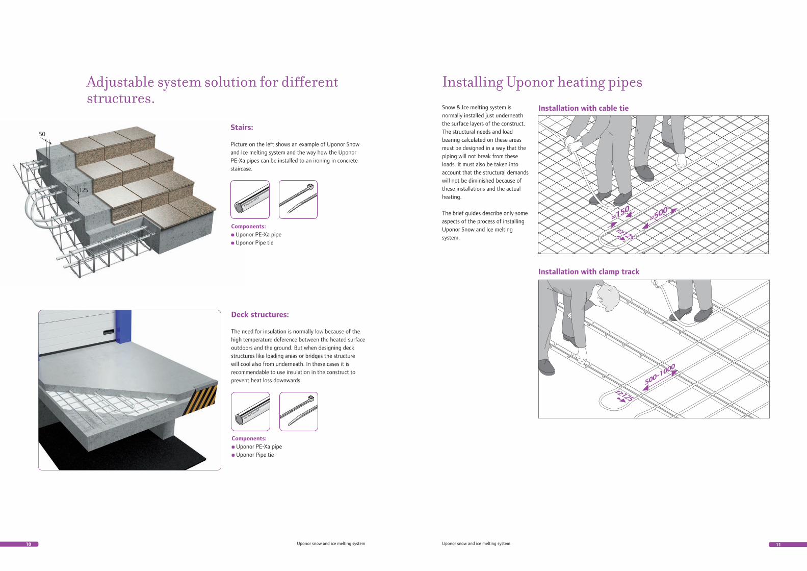
Picture on the left shows an example of Uponor Snow and Ice melting system and the way how the Uponor PE-Xa pipes can be installed to an ironing in concrete staircase.
Deck structures:
The need for insulation is normally low because of the high temperature deference between the heated surface outdoors and the ground. But when designing deck structures like loading areas or bridges the structure will cool also from underneath. In these cases it is recommendable to use insulation in the construct to prevent heat loss downwards.
Components: Uponor PE-Xa pipe Uponor Pipe tie
Installing Uponor heating pipesSnow & Ice melting system is normally installed just underneath the surface layers of the construct. The structural needs and load bearing calculated on these areas must be designed in a way that the piping will not break from these loads. It must also be taken into account that the structural demands will not be diminished because of these installations and the actual heating.
The brief guides describe only some aspects of the process of installing Uponor Snow and Ice melting system.
Installation with cable tie
Installation with clamp track
50
125
12 13Uponor snow and ice melting system Uponor snow and ice melting system
Uponor - Nr. d [mm] s [mm] L [m]
1005278 25 2,3 220
1005282 25 2,3 240
1005277 25 2,3 270
1005281 25 2,3 300
1006746 25 2,3 220
1006750 25 2,3 340
1033321 25 2,3 240
1045072 25 2,3 340
1023448 25 2,3 205
1047615 25 2,3 303
1047617 25 2,3 240
1047618 25 2,3 640
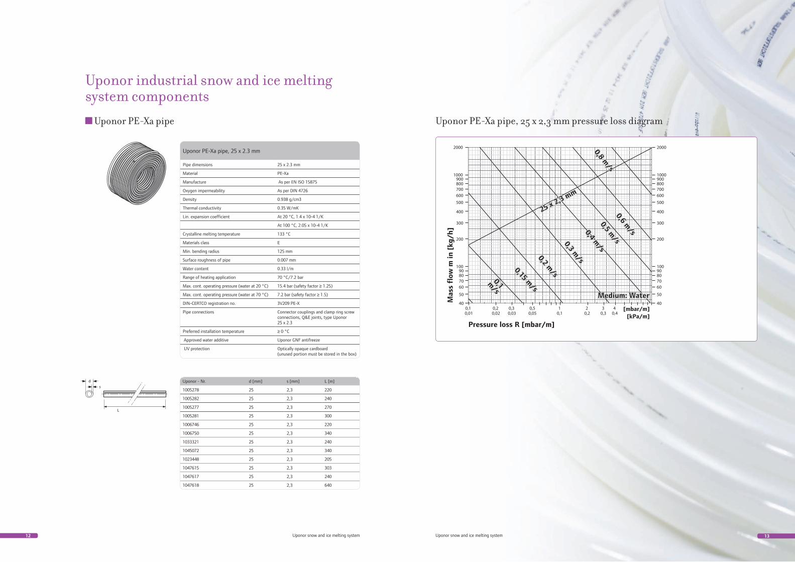
Uponor PE-Xa pipe, 25 x 2.3 mm
Pipe dimensions 25 x 2.3 mm
Material PE-Xa
Manufacture As per EN ISO 15875
Oxygen impermeability As per DIN 4726
Density 0.938 g/cm3
Thermal conductivity 0.35 W/mK
Lin. expansion coefficient At 20 °C, 1.4 x 10⁻⁴ 1/K
At 100 °C, 2.05 x 10⁻⁴ 1/K
Crystalline melting temperature 133 °C
Materials class E
Min. bending radius 125 mm
Surface roughness of pipe 0.007 mm
Water content 0.33 l/m
Range of heating application 70 °C/7.2 bar
Max. cont. operating pressure (water at 20 °C) 15.4 bar (safety factor ≥ 1.25)
Max. cont. operating pressure (water at 70 °C) 7.2 bar (safety factor ≥ 1.5)
DIN-CERTCO registration no. 3V209 PE-X
Pipe connections Connector couplings and clamp ring screw connections, Q&E joints, type Uponor 25 x 2.3
Preferred installation temperature ≥ 0 °C
Approved water additive Uponor GNF antifreeze
UV protection Optically opaque cardboard (unused portion must be stored in the box)
Uponor PE-Xa pipe Uponor PE-Xa pipe, 25 x 2,3 mm pressure loss diagram
Uponor industrial snow and ice melting system components
14 15Uponor snow and ice melting system Uponor snow and ice melting system
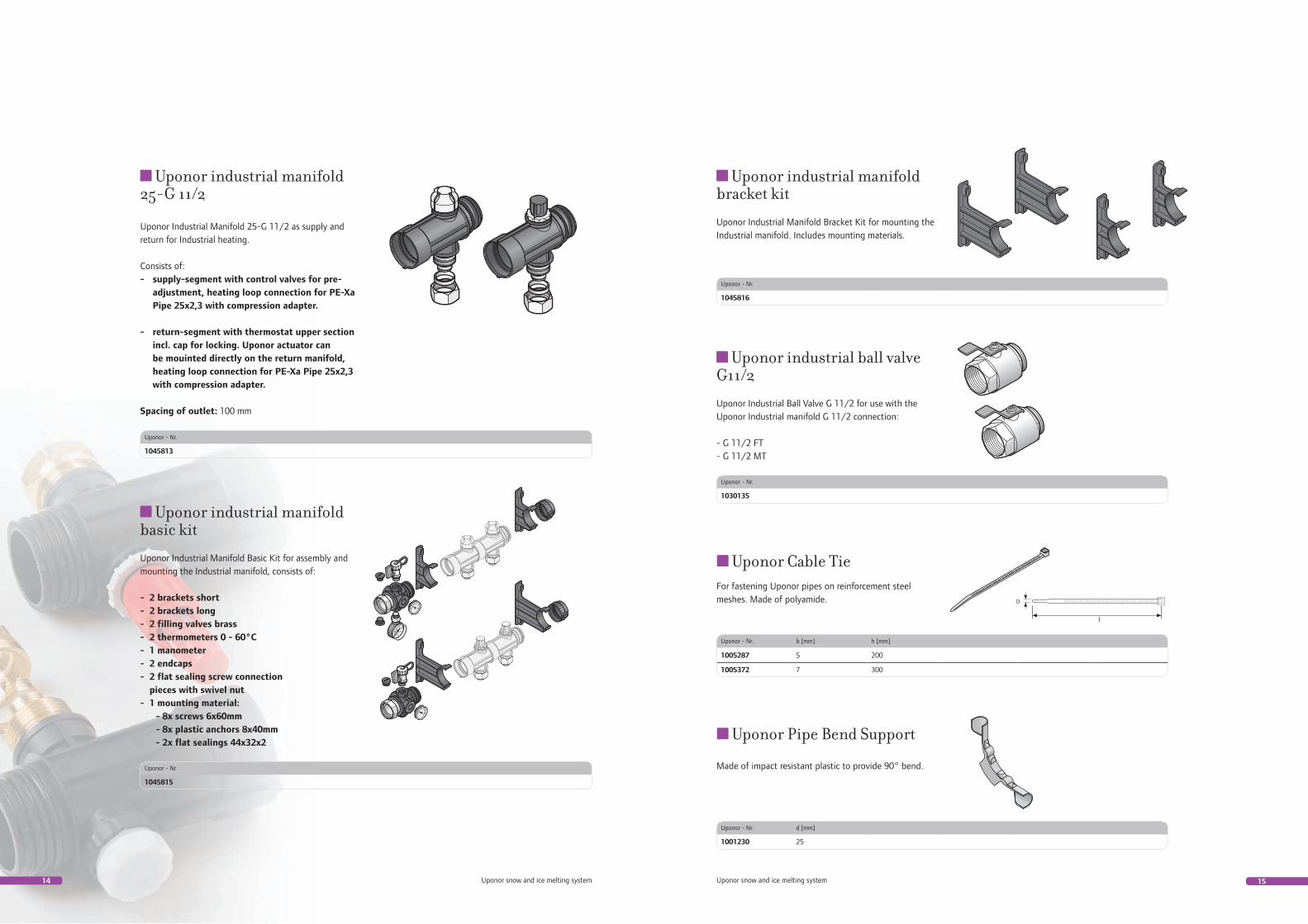
Uponor industrial manifold 25-G 11/2
Uponor Industrial Manifold 25-G 11/2 as supply andreturn for Industrial heating.
Consists of:- supply-segment with control valves for pre- adjustment, heating loop connection for PE-Xa Pipe 25x2,3 with compression adapter.
- return-segment with thermostat upper section incl. cap for locking. Uponor actuator can be mouinted directly on the return manifold, heating loop connection for PE-Xa Pipe 25x2,3 with compression adapter.
Spacing of outlet: 100 mm
Uponor industrial ball valve G11/2
Uponor Industrial Ball Valve G 11/2 for use with the Uponor Industrial manifold G 11/2 connection:
- G 11/2 FT - G 11/2 MT
Uponor industrial manifold basic kit
Uponor Industrial Manifold Basic Kit for assembly and mounting the Industrial manifold, consists of:
- 2 brackets short - 2 brackets long - 2 filling valves brass - 2 thermometers 0 - 60°C - 1 manometer - 2 endcaps - 2 flat sealing screw connection pieces with swivel nut - 1 mounting material: - 8x screws 6x60mm - 8x plastic anchors 8x40mm - 2x flat sealings 44x32x2
Uponor industrial manifold bracket kit
Uponor Industrial Manifold Bracket Kit for mounting the Industrial manifold. Includes mounting materials.
Uponor - Nr.
1045813
Uponor - Nr.
1045815
Uponor - Nr.
1045816
Uponor - Nr.
1030135
Uponor Cable Tie
Uponor Pipe Bend Support
Uponor - Nr. d [mm]
1001230 25
Uponor - Nr. b [mm] h [mm]
1005287 5 200
1005372 7 300
For fastening Uponor pipes on reinforcement steel meshes. Made of polyamide.
Made of impact resistant plastic to provide 90° bend.
16 17Uponor snow and ice melting system Uponor snow and ice melting system
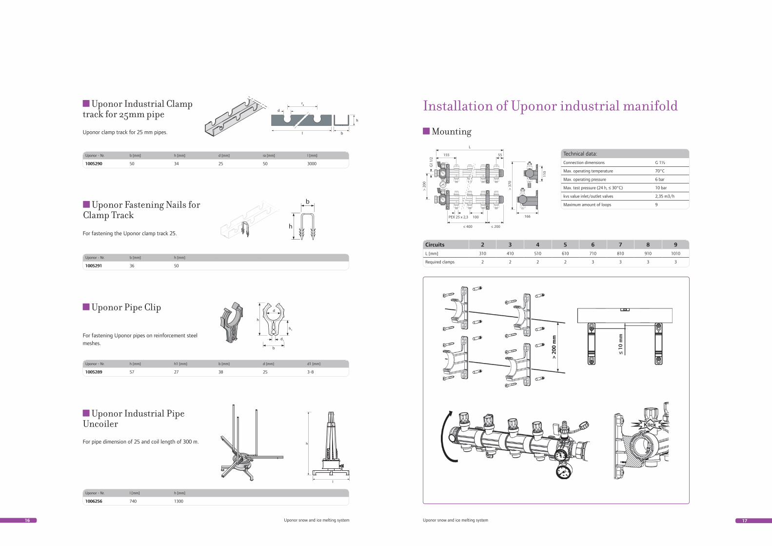
Uponor Industrial Clamp track for 25mm pipe
Uponor Pipe Clip
Uponor Fastening Nails for Clamp Track
Uponor - Nr. b [mm] h [mm] d [mm] ra [mm] l [mm]
1005290 50 34 25 50 3000
Uponor - Nr. b [mm] h [mm]
1005291 36 50
Uponor - Nr. h [mm] h1 [mm] b [mm] d [mm] d1 [mm]
1005289 57 27 38 25 3-8
Uponor clamp track for 25 mm pipes.
For fastening the Uponor clamp track 25.
For fastening Uponor pipes on reinforcement steel meshes.
Uponor Industrial Pipe Uncoiler
Uponor - Nr. l [mm] h [mm]
1006256 740 1300
For pipe dimension of 25 and coil length of 300 m.
Technical data:
Connection dimensions G 1½
Max. operating temperature 70°C
Max. operating pressure 6 bar
Max. test pressure (24 h, ≤ 30°C) 10 bar
kvs value inlet/outlet valves 2,35 m3/h
Maximum amount of loops 9
Circuits 2 3 4 5 6 7 8 9
L [mm] 310 410 510 610 710 810 910 1010
Required clamps 2 2 2 2 3 3 3 3
Installation of Uponor industrial manifold
Mounting
18 19Uponor snow and ice melting system Uponor snow and ice melting system
B
A
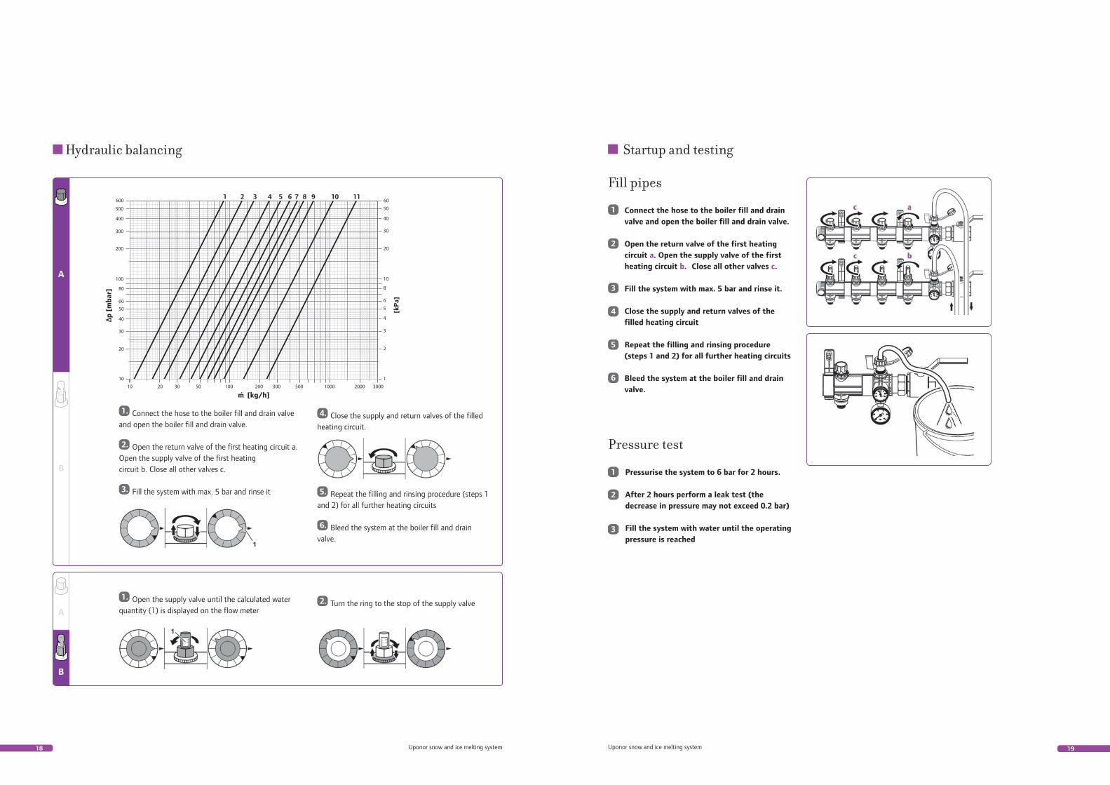
1. Connect the hose to the boiler fill and drain valve and open the boiler fill and drain valve.
2. Open the return valve of the first heating circuit a. Open the supply valve of the first heating circuit b. Close all other valves c.
3. Fill the system with max. 5 bar and rinse it
4. Close the supply and return valves of the filled heating circuit.
5. Repeat the filling and rinsing procedure (steps 1 and 2) for all further heating circuits
6. Bleed the system at the boiler fill and drain valve.
B
A
1. Open the supply valve until the calculated waterquantity (1) is displayed on the flow meter
2. Turn the ring to the stop of the supply valve
Hydraulic balancing
Connect the hose to the boiler fill and drain valve and open the boiler fill and drain valve.
Open the return valve of the first heating circuit a. Open the supply valve of the first heating circuit b. Close all other valves c.
Fill the system with max. 5 bar and rinse it.
Close the supply and return valves of the filled heating circuit
Repeat the filling and rinsing procedure (steps 1 and 2) for all further heating circuits
Bleed the system at the boiler fill and drain valve.
Fill pipes
c a
c b
6
5
4
3
2
1
Pressurise the system to 6 bar for 2 hours.
After 2 hours perform a leak test (the decrease in pressure may not exceed 0.2 bar)
Fill the system with water until the operating pressure is reached
Pressure test
3
2
1
Startup and testing

Upo
nor I
ndus
tria
l Sno
w a
nd Ic
e m
eltin
g Sy
stem
12/
2010
Uponor CorporationVantaaFinlandwww.uponor.com
Uponor offers construction professionals uncompromising quality, leadingedge expertise and long-lasting partnerships. As a leading international company, we are known for our solutions that help create better human environments.
Uponor’s Simply More philosophy includes services for all stages of the construction process – from the fi rst concept of a project to a building in use.