Superconducting Lines for the Transmission of Large ... › rlg › Garwin-Matisoo IEEE...
11
538 PROCEEDINGS OF m~ m, VOL. 55, NO. 4, APRIL 1967 one of the roots to the characteristic equation. This is also a sufficient condition for amplification to occur. REFERENCES [ l ] C. W. Barnes, “Conservative coupling between modes of propaga- tion-A tabular summary,” Proc. ZEEE, vol. 52, pp. 6473, January 1964; see also Proc. ZEEE, vol. 52, p. 295, March 1964. [2] P. K. Tien, “Parametric amplification and frequency mixing in propagating circuits,” J. Appl. Phys., vol. 29, p. 1347,1958. [3] D. L. Bobroff, “Coupled-modes analysis of the phonon-photon parametric backward-wave oscillator,” J. Appl. Phys., vol. 36, p. 1760,1965. [4] D. I. Breitzer and E. W. Sard, “Low frequency prototype backward- wave parametric amplifier,” Microwave J., vol. 2, p. 34, 1959. [5] H. Hsu, “Backward traveling-wave parametric amplifier,” presented at the 1960 Internat’l Solid-state Circuits Conf., University of Penn- sylvania, Philadelphia. [6] S. Okwit and E. W. Sard, “Constant-output-frequency, Octave tuning range backward-wave parametric amplifier,” IRE Trans. on Electron Devices, vol. ED-8, pp. 540-549, November 1961. [7] S. Okwit, M. I. Grace, and E. W. Sard, “UHF backward-wave parametric amplifier,” IRE Trans. on Microwave Theory and Tech- niques, vol. MTT-10, pp. 558-563, November 1962. [8] B. A. Auld and H. Matthews, “Parametric traveling-wave acoustic amplification in ferromagnets,” J. Appl. Phys., vol. 36, p. 3599, 1965. [9] R. L. ComstOck, “Nondegenerate parallel pumping of magneto- elastic waves,” J. Appl. Phys., vol. 37, p. 992, 1966. [lo] N. M. Kroll, “Parametric amplification in spatially extended media and application to the design of tunable oscillators at optical fre- quencies,” Phys. Rev., vol. 127, p. 1207, 1962. [I 1] L. Brillouin, Wave Propagation in Periodic Structures, 2nd ed. New York: Dover, 1953. [12] P. K. Tien, “Noisein parametric amplifiers,” Acta Electronica, vol. 4, no. 4, 1960. Superconducting Lines for the Transmission of Large Amounts of Electrical Power over Great Distances R. L. GARWIN AND J. MATISOO Abstract-As an application of highfield, higacovrent sapercoad&ors we sketch the design of a power lmmmid~ line to carry 100 GW (10” watis) of direct ament over a diptpoce of lo00 km. (It is interesting to note that the present peak power geaerating capacity of the United States is ap proximately 200 GW, or jmt twice the capacity of the proposed line.) Such a~incoatrnsttoowmndeofordinnrymeelwoulddissipPtewwofthe lioe for refrigeration. The cwpe~peaces of negli@e f loss are dstanti.l: powert * wouldbemoreecwomicnlthnthepreseot ptncticeofshippingeorltothe~innhicheleetricityisgeneratedad coasllmed; generating-plant site selectioo codd be made almost entirely 00 ecoIlomic eo l s i deret i om; at tbe same time, thermal ad air-pollution pmb- lemfconldbeminimized;novelpowersomresdbecolsidered. powertRBsmittedtbr~it,nWoaghitis~rytotnppowerfromthe .. Tbe power he would be made of Nb,S ad would be refrigerated to 4°K. Tbe power must be tmnmitted ps direct carrent, rather thn as alter- &img auremt, become the very large (comparatively) alternnting-carrent losses would requireexcessive refrigeration capaaty. SgecificPlly,weshalldiscessalineat200kVcarrying05x1O6A.Tbe investment in the he w i l be approximately S806 miUion, or S.M/kW. Of this, some S6.M/kW is line cost, the remainder being converter cost, nhict4ofeonrse,isthespmefornnordinnrydche.Incom~niththe We have investigated iu m e detail the PrOMemp of refrigeration along the~~thoseofheptlefkthrollghthewiresahichdeliverpowerto cpstomers at room temperatnre. The elliciency of the he is greater thtn 99.9 percent (power trpnomitted 1 - the power drawn off to w refrigemtion equipment, all divided by tmnmitted power). shippingof~theinvestmentcostwwMberepaid~tenmooths Manuscript received June 24, 1966; revised October 31, 1966, and February 15,1967. R. L. Garwin is with the IBM Watson Laboratory, Columbia Uni- versity, New York, N. Y. He was formerly with the IBM Thomas J. Watson Research Center, Yorktown Heights, N. Y. J. Matisoo is with the IBM Thomas J. Watson Research Center, York- town Heights, N. Y. whiletbet~disarosioaispmbaMycorrect,thecost6goresdonot indadeengh&ngexpeditaresanddonotcrmiderindetailthecastsib vohred m pro- the redmuhcy md safety factors for, say, a failure rate ofoeepertemyearswithrtimeofafewseeoedstorestorepower. ~isnotan~~ybrtratherap~~explorntionof feasibility. Provided satistaxtory supe r - cabIe of the nature de- scribed can be developed, the me of Japercoadocthrg liues for power hns- mission appearsfeasible. W”Y it is wcessuy or desirable is mother matter entirely. INTRODUCTION B EFORE WORLD WAR 11, there was little incentive for the electric utility companies to develop means of long-distance transmission of electrical energy. In fact, the only high-voltage long lines in existence were those required to transport power from hydroelectric sources to population centers. Electrical energy transmission over long distances was avoided mostly because of the high cost of transmission over lines (a compromise between power loss in a small conductor and the capital expense of a large- diameter line). It was more economical to build generating stations near the major consumption centers, and to trans- port the energy to the generating stations in some other way; for example, as coal by barge or railway. This pro- cedure was also consistent with the structureof the electric utility industry, which not long ago consisted of many com- paratively small local companies, each serving its own area, quite independently of one another. The recent (and future projected) growth of the utility
Transcript of Superconducting Lines for the Transmission of Large ... › rlg › Garwin-Matisoo IEEE...

538 PROCEEDINGS OF m~ m, VOL. 55, NO. 4, APRIL 1967
one of the roots to the characteristic equation. This is also a sufficient condition for amplification to occur.
REFERENCES [ l ] C. W. Barnes, “Conservative coupling between modes of propaga-
tion-A tabular summary,” Proc. ZEEE, vol. 52, pp. 6473, January 1964; see also Proc. ZEEE, vol. 52, p. 295, March 1964.
[2] P. K. Tien, “Parametric amplification and frequency mixing in propagating circuits,” J. Appl. Phys., vol. 29, p. 1347,1958.
[3] D. L. Bobroff, “Coupled-modes analysis of the phonon-photon parametric backward-wave oscillator,” J. Appl. Phys., vol. 36, p. 1760, 1965.
[4] D. I. Breitzer and E. W. Sard, “Low frequency prototype backward- wave parametric amplifier,” Microwave J. , vol. 2, p. 34, 1959.
[5] H. Hsu, “Backward traveling-wave parametric amplifier,” presented at the 1960 Internat’l Solid-state Circuits Conf., University of Penn- sylvania, Philadelphia.
[6] S. Okwit and E. W. Sard, “Constant-output-frequency, Octave tuning range backward-wave parametric amplifier,” IRE Trans. on Electron Devices, vol. ED-8, pp. 540-549, November 1961.
[7] S. Okwit, M. I. Grace, and E. W. Sard, “UHF backward-wave parametric amplifier,” IRE Trans. on Microwave Theory and Tech- niques, vol. MTT-10, pp. 558-563, November 1962.
[8] B. A. Auld and H. Matthews, “Parametric traveling-wave acoustic amplification in ferromagnets,” J. Appl. Phys., vol. 36, p. 3599, 1965.
[9] R. L. ComstOck, “Nondegenerate parallel pumping of magneto- elastic waves,” J. Appl. Phys., vol. 37, p. 992, 1966.
[lo] N. M. Kroll, “Parametric amplification in spatially extended media and application to the design of tunable oscillators at optical fre- quencies,” Phys. Rev., vol. 127, p. 1207, 1962.
[ I 1 ] L. Brillouin, Wave Propagation in Periodic Structures, 2nd ed. New York: Dover, 1953.
[12] P. K. Tien, “Noise in parametric amplifiers,” Acta Electronica, vol. 4, no. 4, 1960.
Superconducting Lines for the Transmission of Large Amounts of Electrical Power
over Great Distances R. L. GARWIN AND J. MATISOO
Abstract-As an application of highfield, higacovrent sapercoad&ors we sketch the design of a power lmmmid~ line to carry 100 GW (10” watis) of direct ament over a diptpoce of lo00 km. (It is interesting to note that the present peak power geaerating capacity of the United States is a p proximately 200 GW, or jmt twice the capacity of the proposed line.) Such a~incoatrnsttoowmndeofordinnrymeelwoulddissipPtewwofthe
lioe for refrigeration. The cwpe~peaces of negli@e f loss are dstanti.l: powert * wouldbemoreecwomicnlthnthepreseot ptncticeofshippingeorltothe~innhicheleetricityisgeneratedad coasllmed; generating-plant site selectioo codd be made almost entirely 00
ecoIlomic eollsideretiom; at tbe same time, thermal ad air-pollution pmb- l emfcon ldbemin imized;nove lpowersomresdbeco l s idered .
p o w e r t R B s m i t t e d t b r ~ i t , n W o a g h i t i s ~ r y t o t n p p o w e r f r o m t h e . .
Tbe power he would be made of Nb,S ad would be refrigerated to 4°K. Tbe power must be tmnmitted ps direct carrent, rather thn as alter- &img auremt, become the very large (comparatively) alternnting-carrent losses would require excessive refrigeration capaaty.
SgecificPlly,weshalldiscessalineat200kVcarrying05x1O6A.Tbe investment in the h e will be approximately S806 miUion, or S.M/kW. Of this, some S6.M/kW is line cost, the remainder being converter cost, nhict4ofeonrse,isthespmefornnordinnrydche.Incom~niththe
We have investigated iu m e detail the PrOMemp of refrigeration along the~~thoseofheptlefkthrol lghthewiresahichdel iverpowerto cpstomers at room temperatnre. The elliciency of the he is greater thtn 99.9 percent (power trpnomitted 1- the power drawn off to w refrigemtion equipment, all divided by tmnmitted power).
shippingof~theinvestmentcostwwMberepaid~tenmooths
Manuscript received June 24, 1966; revised October 31, 1966, and February 15,1967.
R. L. Garwin is with the IBM Watson Laboratory, Columbia Uni- versity, New York, N. Y. He was formerly with the IBM Thomas J. Watson Research Center, Yorktown Heights, N. Y.
J. Matisoo is with the IBM Thomas J. Watson Research Center, York- town Heights, N. Y.
whiletbet~disarosioaispmbaMycorrect,thecost6goresdonot indadeengh&ngexpeditaresanddonotcrmiderindetailthecastsib vohred m pro- the redmuhcy md safety factors for, say, a failure rate ofoeepertemyearswithrtimeofafewseeoedstorestorepower.
~ i s n o t a n ~ ~ y b r t r a t h e r a p ~ ~ e x p l o r n t i o n o f feasibility. Provided satistaxtory super- cabIe of the nature de- scribed can be developed, the me of Japercoadocthrg liues for power h n s - mission appears feasible. W”Y it is wcessuy or desirable is mother matter entirely.
INTRODUCTION
B EFORE WORLD WAR 11, there was little incentive for the electric utility companies to develop means of long-distance transmission of electrical energy. In
fact, the only high-voltage long lines in existence were those required to transport power from hydroelectric sources to population centers. Electrical energy transmission over long distances was avoided mostly because of the high cost of transmission over lines (a compromise between power loss in a small conductor and the capital expense of a large- diameter line). It was more economical to build generating stations near the major consumption centers, and to trans- port the energy to the generating stations in some other way; for example, as coal by barge or railway. This pro- cedure was also consistent with the structure of the electric utility industry, which not long ago consisted of many com- paratively small local companies, each serving its own area, quite independently of one another.
The recent (and future projected) growth of the utility
Paul M. Grant
Text Box
From the Digital Library of Paul M. Grant, www.w2agz.ocm

GARWIN AND MATISOO: SUPERCONDUCTING TRANSMISSION LINES 539
industry has forced a re-examination of the economics of past practice. In particular, although the costs of coal transportation by railway have been decreasing, this cost is still substantial.' Furthermore, the utilities have recently become aware of the advantages of power pooling. By tying together formerly independent power systems they can save in reserve capacity (particularly if the systems are in different regions of the country), because peak loads, for example, occur at different times of day, or in different seasons. To take advantage of these possible economies. facilities must exist for the transmission of very large blocks of electrical energy over long distances at reasonable cost.
Other problems which face the utility industry also re- quire for their solution economical means of electrical en- ergy transmission. Among these are generating-station site location, and full utilization of existmg or of novel power sources. The location of fossil-fuel plants near or in high- populationdensity areas has disadvantages. Suitable sites may be unavailable or very expensive; air pollution or thermal pollutioa problems may limit the generating capac- ity below optimum size; there is still much resistance to placing nuclear power plants in congested areas, because of possible dangers, no matter how improbable they may be. Distant sites make available economies of scale which are particularly important in nuclear plants.
Should it be possible to transmit large amounts of electri- cal energy with negligible loss, fossil-fuel as well as nuclear plants could be placed so as to offer no hazard to urban areas, and the choice of location could be made entirely on economic considerations ; in particular, mine-mouth opera- tion of steam plants would lead to large savings in coal transportation costs.
Economical transmission would also make possible serious consideration of alternative sources of energy; for example, one might build large solar generators in deserts or tap sources of hydroelectric power much more distant than those now considered practical for development.
In this paper we consider the problem of economical electrical energy transmission; in particular, the problem of transmitting very large blocks (100 GW) over long distances (loo0 km). These numbers, while large, are not unreason- ably so, since inter-ties of 4-GW capacity over such a dis- tance are currently under serious consideration [3]. Large block transmission is especially important since, whereas satisfactory conventional solutions exist for the trans- mission of multi-megawatt blocks over distances of -500 km, this is not the case, as will be made clear in this paper, for 100 GW over loo0 km.
There are, as in every engmeering problem, a number of possible alternative solutions, the choice among which must be made on the basis of cost or return. The first alternative, of course, is not to transmit electrical energy at all but rather
The average mine cost of coal is $4.50 per ton (see Howard [ I I), whereas the average transportation cost (1962) was $3.37 per ton [l]. Since approximately 1.2 kwh of electrical energy is obtained per pound of coal, the transportation cost of coal is approximately 1.4 mills/kWh. This transportation cost is an appreciable fraction of busbar energy costs (l964)of6.8mills/kWh(Olmsted [2]).
to ship coal. The shipment of coal does offer some ad- vantages; for example, easy storage of energy near the con- sumer, which eliminates, or at least minimizes, the peak- load problem on the transmission line, and provides security against short-term (few-week) interruptions of the transportation system.
The transportation cost of coal for a power transmission task of this magnitude, however, exceeds $1 billion per year. This cost is large; therefore, considerable effort is justified to reduce it.
Another alternative is conventional (probably dc) long- distance EHV transmission by ordinary metallic conduc- tors. This solution has the advantage of the use of existing and proven technology. On the other hand this, too, is expensive. Lower bounds for cost involving such a line are $670 million for the conductor, perhaps several times this amount for towers and, most important, a line loss of -$340 million per year. To these we must add converter costs, if the transmission is to be at dc (Appendix A).
We propose as a solution a superconducting line; i.e., a transmission system using superconductors to carry cur- rent. The superconductors would, of course, be refrigerated so that their resistivity is zero. The major power loss then would be the power required to maintain the line at 4°K.
In what follows we shall sketch the design of such a line.
DETAILS OF THE PROPOSED TRANSMISSION LINE The proposed transmission line consists of two insulated
superconducting cables which are maintained at 4°K (the boiling point of liquid helium at one atmosphere), a con- venient working temperature.
The power transported down the line is still, of course, proportional to the voltage difference between the two cables, and to the current flowing (with essentially zero dissipation) in the cables.
The design problem can be divided into three rather nat- ural, but obviously very much interdependent parts: the superconducting cable itself, the refrigeration system, and the transmission line as a whole, including its relationship to existing facilities.
The cable problem involves : the choice of an appropriate superconductor and of cable dimensions based on the necessary currents and voltages; demonstration of the need for dc transmission, which is required by the economics of the refrigeration system and has far-reaching consequences for the line as a whole; finally, some details of construction.
The refrigeration system uses the principles of the com- mon Dewar flask (Thermos bottle); i.e., the primary coolant is liquid helium (He), the insulation is vacuum, and the radiant heat shield is cooled by liquid nitrogen (N2). The power to run the refrigerators is tapped from the line.
Finally, there are the problems of providing for re- dundancy and repair of the transmission line and the tie-in problems to ac systems at ordinary temperature.
A . Superconducting Cable As the superconducting material from which the cable is
made, we choose niobium-tin (Nb,Sn). At temperatures
540 PROCEEDINGS OF THE IEEE, APRIL 1967
low compared with its “critical temperature” (T,= 18”K), this material remains superconducting in a field of 100 OOO G2 while carrying current densities of 200 OOO A/cm2 [4]. (For a brief summary of properties of superconductors, see Appendix B.) If we choose the transmission voltage as 200 kV, the total current must be 0.5 x lo6 A. Limiting the current density to 10’ A/cm2 implies a superconductor cross section of 5 cm2. This choice insures that the self-magnetic field is below the critical one of 10’ G, even for cable made entirely of superconductor; if the cable is “stabilized” [6] by the inclusion of low-resistivity aluminum or copper, which occupies space and thus increases the radius, the magnetic field will, then, be still smaller.
The choice of transmission voltage of 200 kV is obviously conservative since 345-kV conventional insulated under- ground lines are in use [7]. It is probable, since insulation problems are much eased at low temperatures, that the transmission voltage could be raised to 500 kV, thereby achieving a 2.5-fold increase in the power transmission capability of the line, or alternatively a 2.5-fold reduction in the current and thus in the cross section (and cost) of the superconductor.
Nearly all transmission lines in the world today transmit alternating current. The major reason is the ease with which the voltage can be changed (“transformed”) from link to link along the system. Even so, there are reasons to prefer dc transmission under some circumstances. Insulation require- ments are less severe with dc transmission and only two con- ductors are required per dc circuit rather than the three re- quired in the ac case. Furthermore, the maximum practical length of ac cable is limited by the capacitive “charging” current, which, of course, does not exist on dc lines.
There are, however, far more compelling reasons for preferring dc transmission on superconducting lines.
Alternating currents exert alternating forces on flux lines in the superconductor causing irreversible motion of the flux lines (thus, loss). This produces heat. In fact, as we shall see below, normal heat leak into the line is - 4 x W/cm. Hysteresis losses, if transmission were at 60 Hz, would exceed this by a factor or lo8, making line refrigeration im- possible. [For details, see Appendix Cy (1) through (3).]
Note added in proof: A recent paper [21] demonstrates the unpracticability of ac transmission on refrigerated lines. Note, however, that the coolant circulation in Fig. 3 of that paper (“twinduct jacket”) is unsatisfactory because such a countercurrent flow does not remove appreciable heat.
Even with a (nominally) dc line, fluctuating demand and particularly the initial loading of the line cause dissipation, largely as a result of hysteresis in flux motion. This loss is a serious design consideration if the line is not to serve only as a base supply, at constant load.
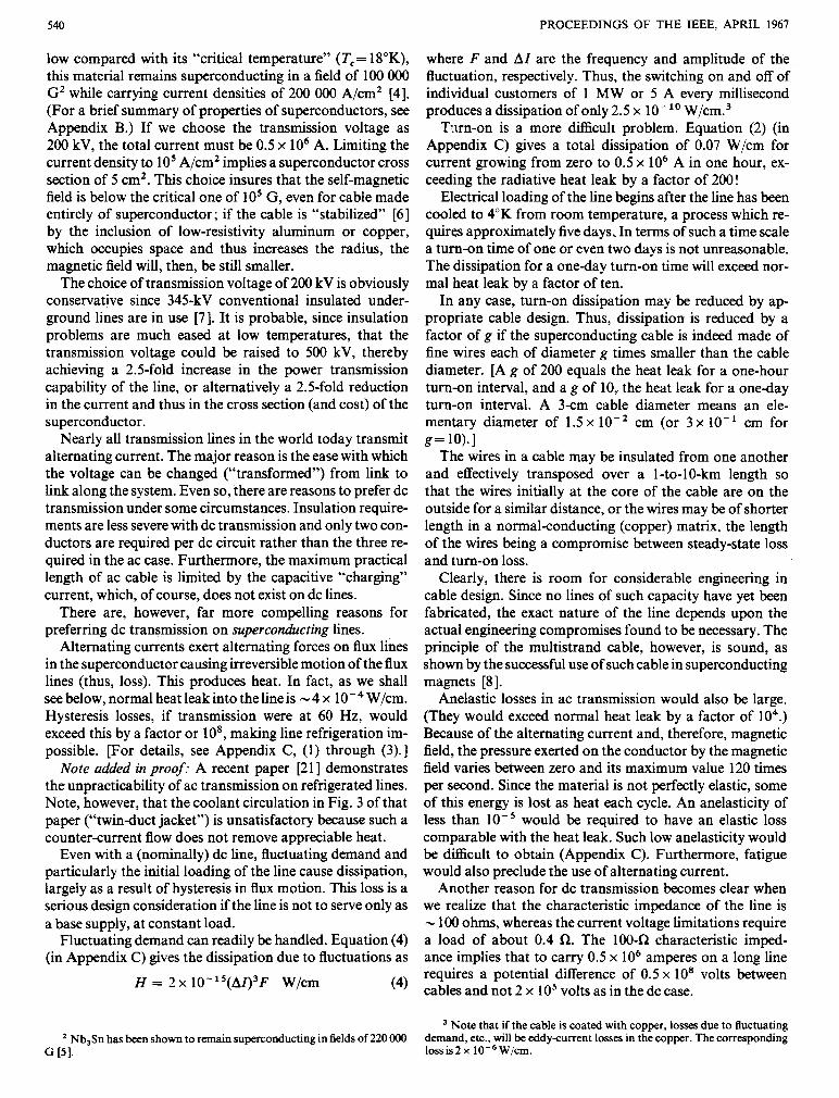
Fluctuating demand can readily be handled. Equation (4) (in Appendix C) gives the dissipation due to fluctuations as
H = 2 x 10-’’(AI)3F W/cm (4)
where F and AI are the frequency and amplitude of the fluctuation, respectively. Thus, the switching on and off of individual customers of 1 MW or 5 A every millisecond produces a dissipation of only 2.5 x 10- lo W / C ~ . ~
Txrn-on is a more difficult problem. Equation (2) (in Appendix C) gives a total dissipation of 0.07 W/cm for current growing from zero to 0.5 x lo6 A in one hour, ex- ceeding the radiative heat leak by a factor of 200!
Electrical loading of the line begins after the line has been cooled to 4°K from room temperature, a process which re- quires approximately five days. In terms of such a time scale a turn-on time of one or even two days is not unreasonable. The dissipation for a oneday turn-on time will exceed nor- mal heat leak by a factor of ten.
In any case, turn-on dissipation may be reduced by a p propriate cable design. Thus, dissipation is reduced by a factor of g if the superconducting cable is indeed made of fine wires each of diameter g times smaller than the cable diameter. [A g of 200 equals the heat leak for a one-hour turn-on interval, and a g of 10,. the heat leak for a oneday turn-on interval. A 3cm cable diameter means an ele- mentary diameter of 1.5 x cm (or 3 x 10- cm for g = lo).]
The wires in a cable may be insulated from one another and effectively transposed over a 1-to-10-km length so that the wires initially at the core of the cable are on the outside for a similar distance, or the wires may be of shorter length in a normalconducting (copper) matrix, the length of the wires being a compromise between steady-state loss and turn-on loss.
Clearly, there is room for considerable engineering in cable design. Since no lines of such capacity have yet been fabricated, the exact nature of the line depends upon the actual engineering compromises found to be necessary. The principle of the multistrand cable, however, is sound, as shown by the successful use of such cable in superconducting magnets [8].
Anelastic losses in ac transmission would also be large. (They would exceed normal heat leak by a factor of lo4.) Because of the alternating current and, therefore, magnetic field, the pressure exerted on the conductor by the magnetic field varies between zero and its maximum value 120 times per second. Since the material is not perfectly elastic, some of this energy is lost as heat each cycle. An anelasticity of less than would be required to have an elastic loss comparable with the heat leak. Such low anelasticity would be difficult to obtain (Appendix C). Furthermore, fatigue would also preclude the use of alternating current.
Another reason for dc transmission becomes clear when we realize that the characteristic impedance of the line is - 100 ohms, whereas the current voltage limitations require a load of about 0.4 ZZ. The 10042 characteristic imped- ance implies that to carry 0.5 x lo6 amperes on a long line requires a potential difference of 0.5 x 10’ volts between cables and not 2 x IO5 volts as in the dc case.
Note that if the cable is coated with copper, losses due to fluctuating Nb3Sn has been shown to remain superconducting in fields of 220 OOO demand, etc., will be eddy-cument losses in the copper. The corresponding
G [51. loss is2 x loT6 w/cm.

GARWIN AND MATISOO: SUPERCONDUCTING TRANSMISSION LINES 54 1
Unfortunately, superconducting cable is not produced or shipped in infinite lengths. T h s means that it is necessary to consider how to make joints. It will be difficult to make superconducting joints by the common methods since ordi- nary soft superconductors would be quenched anyhow in fields of los gauss. Therefore, we estimate the dissipation caused by pure normal-metal solder joints.
A cable cross section of 5 cm2 means a mass of - 100 g/cm or 10 tons/km. Since 10 tons is a reasonable shipping weight, we must consider joints every km. A metal-film 10-3cm thick @=lo-* R.cm at 4°K) between butted superconducting sections 5 cm2 in area will present a resistance of 10- l 2 ohms and will thus cause one-watt dissi- pation per joint. This might be handled without excessive temperature rise ( - 0.5"K), but the joint can in addition be skived (the ends cut at 6" angle to the axis of the bundle). The surface of the film is thus increased by a factor of ten, which results in a tenfold reduction of dissipation, or the film thickness can then be allowed to increase to cm to maintain one-watt dissipation per joint. It may be necessary to bleed liquid helium from the supply directly to the joints to keep them at 4°K. Since superconducting joints of lo-'- R resistance have been made in high-field superconducting magnets, the normal joints considered here may be too con- servative.
It is also necessary to consider the steady electromagnetic forces acting on the conductors. These forces are large. They can be approximated (at 0.5 x lo6 A) by a uniform external pressure on each cable of 400 atm (6000 psi) plus a force of repulsion of lo9 dyn/cm (lo6 newtons per meter). Since the strength of plastics at low temperature is 10" dyn/cm2 or more, t h s force of repulsion can be readily supported by allowing the plastic-insulated cables to squeeze against the enclosing 4°K shell, which itself could be made of aluminum alloy or stainless steel some 2 mm in wall thickness. This wall thickness is sufficient to withstand the force.
B. Refrigeration System
A major problem of a superconducting transmission line is the refrigeration system. We shall discuss the design evolved and the reasons for the choices made in this section, and present the detailed calculation of heat leaks, the re- quired refrigeration capacity, the flow rates of the cryogenic fluids, and the necessary vacuum pumping capacity in Ap- pendix D.
Figure 1 shows a section of the entire transmission line and particularly the cooling system. The portion of the line whlch is at 4°K is interior to the 4°K vacuum wall. This pipe contains the liquid He line, as shown, and the two plastic- insulated superconducting cables. These cables may be pulled into the pipe loosely or they may be supported occasionally or continuously. The remainder of the space inside this 4°K wall serves as the He gas return (at one atmosphere).
Surrounding this wall is the 77°K radiation shield, which is cooled by the liquid (and gas) N, line; this, in turn, to- gether with the gaseous N, return line (at 10-atm pressure) is soldered to the sheet-metal radiation shield. The shield is
4mm
Fig. 1. Cross section of the 100-GW line.
slit at the top so that it may be easily separated, should access to the inside become necessary. The shield-pipe assembly might be made in fifty-foot sections and the sections then soldered together, or the shield could be formed from a "continuous" coil at the installation site.
The entire transmission line rests on polyethylene, nylon, or other cheap plastic bridges, which are spaced approxi- mately three meters apart. These supports contribute negli- gible heat leaks.
Finally, there is the vacuum-tight metal trough in a concrete channel which forms the basic unit of support. The concrete channel, which will probably be fabricated at the site, can be either below or above ground. The metal (tin- plated steel, or stainless steel, or perhaps aluminum) is glued with epoxy resin to the concrete. (The metal liner or a foil insert therein acts as an additional heat shield to radiation.) The metal sections of the trough are soldered together (or bonded with epoxy resin and the joints smoothed) so that they are vacuum-tight. To seal the trough, a continuous coil of aluminum (4 mm thick in 5-km sections which weigh 15 tons) is laid on top. Rubber gaskets and O-rings are used to make it vacuum-tight. This cover may be tipped up locally for inspection and repair. It has periodic aper- tures for vacuum pumping lines.
Looking now along the length of the line, the various ele- ments of the cooling system and their spacing are shown in Fig. 2. Every 20 km along the line there are refrigeration stations which supply liquid He and liquid NP. The cryo- genic fluids are pumped along and flow through their respec-

542 PROCEEDINGS OF THE IEEE, APRIL 1967
CIRCULATING CIRCULATING
REFRIGERATION STAT ION
4 -#
X ) km - Fig. 2. A 20-km module of the 1000-km, 100-GW line.
tive pipes. It is not a minor problem, however, to cool 20 km of line from a central source. The difficulty arises be- cause the cryogenic fluid vaporizes as it flows along the pipe. The vapor thus produced reduces the density of the mixed phase and increases the velocity required to maintain the same mass-flow rate, thus necessitating large pumping power. Indeed, even with increased vapor density at low temperatures, the effect is still prohibitive at both He and N2 temperatures.
We solve this problem by use of liquid-vapor separators at 50-m intervals; i.e., floats which vent the gas to the gas- return manifold, while retaining liquid in the supply pipe. The liquid-vapor separators at 50-m intervals also avoid the usual problem of choking on initial cooldown of the line [9].
The separators must be capable of handling an evapora- tion rate of - 1 cm3 of liquid He per second (or 10 cm3/s of gas) and - 3 cm3/s of N2 liquid (or - 60 cm3/s of gas). On cooldown, however, the entire liquid flow rate of the line must be allowed through the separator; clearly, it must be a device whose average position varies considerably but only slowly with demand. Separator design will not be con- sidered further, except for noting that, if necessary, separa- tors may include floats, switches, and motors and that they should fail-safe by closing.
Every 500 meters there is a propeller-type booster circula- tory pump in the liquid He line. These are necessary because flow friction would produce a pressure drop of more than one atmosphere over the 20-km distance between refrigera- tion stations (at the design flow velocity of some 30 cm/s). With the booster pumps, the required pressure rise is - 0.10 atmosphere at a design flow rate of 0.5 liter per second.
Because of the longitudinal contraction of the refrigera- tion system (piping, lines, etc.) on cooldown, it is necessary to insert thermalcontraction bellows 1.5 m long every 500 m. (Thermal contraction problems are discussed in greater detail in Appendix E.)
The remaining major components of the line are the vacuum pumping stations which are spaced every 500 m
along the length of the line. The vacuum pumping problem is really twofold. It is necessary to pump out the line on cooldown in a reasonable length of time (a few hours), which requires comparatively high-speed pumps (5 liters per second every 500 m), i.e., mechanical pumps. However, once the line is cooled the pumping requirements change. The cold He line is an excellent trap for all gases except He, so that only a low-speed ion pump is needed to pump out any small amount of He which may leak in (Appendix D). Indeed, the mechanical pumps may be replaced by liquid nitrogen-cooled zeolite traps, which will pump out the air which initially fills the trough.
W/cm into the 4°K section, whidh requires a refrigeration plant using motor power totaling 0.3 MW per 20-km 'sec- tion. The heat leak into the nitrogen shield will be 10- * W/cm and requires a refrigeration motor capacity of 1.2 MW/20 km.
These are capacities required to keep the line at 4°K. To cool the line initially in a reasonable length of time, addi- tional capacity is required. Thus, we propose a permanently installed He refrigeration motor capacity of 1.5 MW and, if necessary, the trucking in of additional nitrogen refrig- eration for cooldown. Thus, at each of the 20-km refrigera- tion stations we have a total installed motor power of - 3 MW.
To run the refrigerators, we tap power from the line. To provide 3 MW of power, we must plan to draw 15 amperes dc from the line at each 20 km station. The use of 200-kV dc motors is possible but certainly undesirable. Thus, the problem is to draw 15 amperes and convert it with high efficiency and low cost to 60-Hz ac. Since only some 200 MW total is needed for all refrigeration along the line (0.1 percent of acdc-ac conversion load for the transmitted power), the cost of conversion for refrigeration is negligible, even in comparison with the cost of the conversion equip- ment for the transmitted power.
Each tap itself is a source of -0.15-watt heat leak into the line for which no special provision need be made.
Finally, the line as designed has a heat leak of 4 x
GARWIN AND MATISOO: SUPERCONDUCTING TRANSMISSION LINES 543
C. Interconnection and Reliability We shall discuss in this section the interface problems
caused by the low temperature and the necessary direct- current transmission of the line. Since the line must be connected to the room-temperature alternating-current power network, we must consider how this interconnection is to be made and how to solve the problems which arise.
One of the problems involves the heat leak at the ends of the line. Wires of optimum size extending from 4°K to 77°K dissipate and conduct - watts to the helium when one ampere is being removed and returned on a pair of leads [lo]. (Heavier wires conduct more heat to the cold line; thinner wires dissipate more heat.) Since 0.5 x lo6 amperes are being withdrawn, the minimum heat leak is - 5 kW. The additional refrigeration required will cost us an investment of - 1.5 MW of refrigeration motor. The ex- pense is not large, but the cooling must be good enough to prevent the heating of the superconductor and the resulting spread of normal phase down the line. There are several ways to overcome t h s problem. The cable can be un- stranded and the junction spread over 10-m length. This will reduce the cooling required to 5 W/cm whch seems feasible on a width of - 1 meter. There is no doubt that t h s can be done at reasonable cost. The current density in each of the strands is c IO5 A/cm2 and the field will be cc lo5 Oe; in any case, much below the critical values of Nb,Sn.
Another problem is conversion of ac to dc at the source end and of dc to ac at the receiving end of the line. The de- tailed manner of rectification and inversion depends upon the cost of alternatives. In any case, it is likely that 6-phase or possibly even 12-phase rectification will be used, pri- marily to keep the ripple low. In fact, if dissipation due to hysteresis4 is to be less than 10 percent of the normal heat leak, we must have, in a solid superconductor, a ripple cur- rent less than 450 A. With 6-phase rectification the ripple voltage is 8 x lo3 volts (rms) [I I ] , so that the nonresonant current into - 100 R is 80 A (rms). With 12-phase rectifica- tion it is only 20 A (rms); thus the inductance of the line itself serves to reduce. the ripple current. Depending upon cost, various compensating current or rectification schemes can be used to reduce the ripple to a negligible value.
The rectifiers (and inverters) themselves are likely to be mercury-arc pool type 1121 or possibly silicon rectifiers and silicon-controlled rectifiers.
Finally, since it is foolhardy to assume perfect reliability, it would be wise to have a second line nearby with frequent interconnections between the lines as protection against power interruption. Connections are expensive, so rela- tively few are desirable. On the other hand, if no intercon- nections are made, there may be simultaneous breakdown of both lines. We have not definitely resolved this question; the problem is to be able to isolate a defective section of line so that it may be warmed to room temperature and repaired, which requires that there be no voltage across the
In coppercovered cable the losses are the eddycurrent losses in copper. For losses to be 10 percent of heat leak, ripple current must be less than 50 A.
lines. Too much refrigeration capacity would be required to bring the line to room temperature at every 20-km station at all times.
One solution would involve the construction of a “con- ventional” 200-kV, 100-GW dc line either underground or above ground near the superconducting line, with potential interconnections every 20 or 60 km. The normal line might be designed to dissipate, say, 20 percent of the transmitted power in a single 20-km run, for the few days required to repair a fault in a single 20-km module of the superconduct- ing line. Routing around a fault might involve shutting off the power for a few seconds to allow automatic unsoldering of the offending section, making contact with the parallel 20-km section of normal aluminum line (thus incurring a heat leak of some 5 kw at each end of the damaged section) and switching on power as demanded, up to the remaining 80 percent of the superconducting line capacity. The switches required are not operable under load. The indi- vidual aluminum conductors required for the normal line are some 150 cm2 in area, and the whole normal line may cost some $80 million for conductors-a factor 10 or more less than a normal line designed to carry the full 100 GW continuously for the full lo00 km.5 It is clear that there is still room for optimization of this emergency line, its tap spacings, etc. One use of the emergency line is to supply refrigerator and vacuum pump power initially while the superconducting line is still normal..
There are hazards involved in lines carrying such large currents, although they need not be serious. The energy in the line’s magnetic field
is that stored in 1 . 4 ~ lo5 gauss and 1 x lo9 cm3 or 10” joules; that is, approximately the energy in 20 tons of TNT or in two tons of gasoline. In case of a ground fault, one can probably do much better than to isolate the line and to let the energy dissipate in the fault, thus gently blowing up a few feet of line. Even a dead short-circuit across a per- fectly-conducting line will receive only 2 V/z, = (4 x 1 05)/1 O2 =4OOO A until the reflected waves are received from the terminal;. If one short-circuits the line at some point, the current will thus rise in steps of 4O00 A at a mean rate of 400 000 A/s. The resultant arc can hardly be called cata- strophic. Indeed, even if the line conductors themselves are open-circuited, the flashover will short-circuit the line and there will be time for a switch at each refrigerator station to throw -50 R across the line. This will drain the energy in 0.1 second. Since this places 2 x IO9 joules into each resistor, the temperature of each 10-ton cast-iron resistor will rise to 500°C.
D . Cost Estimate (Zeroth Approximation) Here we try to estimate the capital and operating costs of
one of the superconducting transmission lines described
F. A. Otter, Jr., suggested (private communication, May 24, 1966) that this normal line might be made cheaply in this way.

544 PROCEEDINGS OF THE IEEE, APRIL 1967
TABLE I defects by internal fission in the superconductor. If, for example, the critical current density could be increased to
Estimated lo7 A/cm2, a hundred-fold reduction in the cost of the
(millions) superconductor would result. The operating costs arise primarily from the energy
Item cost Basis for Estimate
Superconductor $550 lo4 tons of Nb,Sn @ $26/lb* Refrigeration along $ 25 $0.5 million per He refrigerator
line of 1 kW at 4 K every 20 kmt End refrigeration $ 5 These must handle a total of 10 kW
(2 x 5 kW) or an equivalent of 10 1-kW refrigerators at $0.5 million each
Vacuum pumps $ 1 Assumed $500 per pumping sta-
Fabirfated metal $ 20 tion
Assumed cost of $I/lb and weight of 100 g/cm
Concrete $ 5 Assumed cost of $10/yd3 with total volume o f f yd2 x lo3 km
Converters $200 Cost of mercury-pool rectifiers - $I/kW$ and ofsilicon rectifiers and siliconcontrolled rectifiers - $ I kW$
Total $806 (Million)
* Ultimate cost of Nb,Sn estimated from Nb cost of $36/lb (Chemical and Engineering News, p. 65, February 3,1964) and Sn cost of $2/lb (Year- book of the American Bureau of Metal Statistics for 1962, New York, 1963 p. 132).
t Informal quotation to IBM Corporation by Arthur D. Little, Inc., Cambridge, Mass., February 1966.
Informal quotation to IBM Corporation by General Electric Com- pany on 3-MW mercury-pool rectifier (20 kV, 150 A).
$ Informal quotation to IBM Corporation by International Rectifier Corporation on Silicon rectifier [1.2 kV, 550 A (rms)] and siliconson- trolled-rectifier [1.2 kV, 400 A (rms)].
above. We shall not include in the cost estimate such items as the cost of right-of-way acquisition and clearing (al- though this cost is likely to be an order of magnitude less than that for conventional overhead line), cost of on-site labor, etc. In addition, we do not include the cost of trans- formers at the terminals, since these are required on any conventional line, no matter how short.
A last item which must be considered part of the capital cost of the superconducting line is the converters. There are no single converters currently in existence which are capable of handling the currents and voltages required. There are, however, mercury-pool converters which will safely handle 1 0 0 kV and a few thousand amperes [13]. If we extrapolate from the available cost figures of $l/kW, the total cost for two stations (one at each end) is $200 million which is not very high. (See Table I.)
Although the above costs may be in error by a significant factor, it is clear that the major cost (apart from converters) is the cost of the superconductor. There are various schemes by which the critical current density of superconductors might be increased. One such scheme is to fabricate syn- thetic high-field, high-current superconductors with small superconducting filaments in a suitable normal metal ma- trix [14]. The matrix-metal-to-superconductor-volume ra- tio, as well as the filament diameter and the materials, have to be appropriately chosen, otherwise no high-field proper- ties are obtained [15]. Another scheme has been demon- strated by Bean et al. [16]. They have shown that current densities greater than lo6 A/cm2 (with lo7 A/cm2 con- ceivable) can be obtained (in V,Si) by introduction of
required to liquefy He, N, and the power required to run the vacuum pumps. In normal operation the total He refrigerator-motor power is 0.3 MW x 50 or 15 MW. Therefore, at a busbar cost of 6.8 mil/kWh, the He refrigera- tor operating cost is - $1 million per year. The nitrogen cost is approximately $4 million per year, since the refrigerator capacity for the nitrogen line is roughly four times that of the He line. Thus, the operating costs are approximately $5 million per year which, of course, compares very favor- ably with transmission losses on an ordinary line of this capacity.
SUMMARY AND CONCLUSIONS We summarize the design characteristics of the line as
follows.
Power capacity Voltage (dc) Current (dc) Line temperature Radiation shield Length of line Refrigerator spacing Gas-liquid separator spacing Booster pump spacing Vacuum pump spacing Thermal expansion bellows 1.5 m long (su-
perconductors wound helically) spacing Fraction of power dissipated in line and
leads Fraction of power used for refrigeration
100 GW (10" W) 200 kV (2x IO5 V) 0.5 x lo6 A 4.2"K (liquid helium) 77°K (liquid nitrogen) lo00 km 20 km 50 m 500 m 500 m
MOm
< 10-7 < 1 0 - 3
We have offered another solution to the problem of eco- nomical electrical energy transmission, by sketching a de- sign for a large-capacity, long-distance superconducting line and estimating the capital and operating costs for such a line. If our cost estimates are not too much in error, it is clear that the most economical solution to the over-simpli- fied power transmission problem posed in the Introduction is a superconducting line of the general design described. This becomes particularly apparent when annual costs are examined. Thus, coal transportation cost is approximately $1 billion a year, ordinary EHV transmission losses - $340 million a year, while the superconducting-line "losses" amount to only - $5 million a year. Even the capital costs may favor the superconducting line over conventional EHV. The capital investment in EHV transmission is - $1 to $1.5 billion, whereas the superconducting line cost is - $606 million. (The converter costs are the same for EHV dc and superconducting line and therefore have not been included in the comparison.)
The superconducting line has essentially fixed annual operating costs; i.e., the refrigeration cost is almost inde- pendent of the currentcarrying capacity of the line. Also, the capital costs associated with the refrigeration system are the same regardless of line capacity (assuming fixed 4.2"K operating temperature). What does scale is the super-

GARWIN AND MATISOO: SUPERCONDUCTING TRANSMISSION LINES 545
conductor cost (and converter cost) which varies directly with the power capacity of the line. With ordinary EHV transmission, as the power capacity is reduced there comes a point at which ac transmission becomes practical (elim- inating converters). Losses then scale with power level, as does the capital investment in the line.
Thus, for sufficiently low power levels and over suffi- ciently short transmission distances, it will undoubtedly be more economical to use conventional ac EHV transmis- sion. However, there will exist a power level and distance beyond which superconducting lines will prove more eco- nomical. Clearly, detailed engineering design and cost anal- ysis is necessary to determine exact cross-over points. We have shown, however, that circumstances may be such as to favor the novel approach of a superconducting power line.
APPENDIX A CONVENTIONAL EHV TRANSMISSION
Extra-high-voltage (EHV) transmission is presently car- ried out at 345 and 500 kV with, however, comparatively low capacity (say 1.2 GW).6 If 100 GW were to be trans- mitted in the conventional way, the transmission must be dc and converter costs would be the same as in the super- conducting case.
To carry the current one could use two aluminum (for the sake of argument consider aluminum rather than ACSR) conductors - 1200 cm2 each in area [17] and at much hgher voltage. The resistance of such a line (assum- ing 60°C operating temperature) is -0.3 a, which results in - 5 percent dissipation. To carry 100 GW a distance of lo3 km at 5 percent dissipation would require a current of 1.4 x 1 Os A at 750 kV.
Since there exist no detailed cost estimates in this power range, we obtain a rough lower limit to the costs involved as follows.
The weight of the aluminum conductors is - 8 x lo5 tons, whch at $0.25/lb [18] for aluminum (or %0.38/lb for steel- reinforced cable) is a cost of $440 million for the material or some $670 million for the conductors. The cost of poles. etc., is probably several times t h s amount for a total capital investment of -$1 billion.
The main point, however, is that the line is extracting an annual toll of 5 percent on the electricity transported, or a loss of - 5 x 10” kwh per year at an annual cost of $340 million.
APPENDIX B
SlJhiMARY OF PROPERTIES OF SUPERCONDUCTORS PERTINENT TO CURRENT-CARRYING CAPACITY
Superconductors are materials which below a tempera- ture T, (called the transition temperature) have zero elec- trical resistivity and exclude magnetic fields. T h s is true as long as the current density within the superconductor re- mains below a critical value and as long as applied magnetic fields are sufficiently small. Thus, provided these critical
A 2-GW, 266-kV underground dc system some 85 km long is under contract to be built into London (N. Y. Times, April 30, 1966).
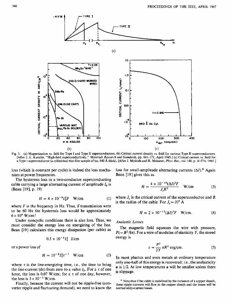
variables (temperature, current density, and magnetic field) have sufficiently low values, the resistance of the supercon- ductor is zero. There are two kinds of superconductors, called Type I and Type II.’ They are distinguished by their rather different magnetic and current carrying behavior (see Fig. 3).
Weak magnetic fields are excluded from the interior of both Type I and Type I1 superconductors (except from a small surface layer, typically on the order of 500 A). As the externally applied magnetic field is increased, in the case of Type I superconductors, the field penetrates completely at the thermodynamic critical field, and at higher fields the behavior is much the same as that of any normal metal.
In Type I1 materials, field penetration begins below the thermodynamic critical field (although this field may be much higher than the corresponding field in Type I ma- terials). The field penetration continues with increasing field, to fields as high as 200 kG in Nb,Sn. It is extremely important to note that a large fraction of the supercon- ductor remains superconducting in high fields, although the magnetic field, on a macroscopic scale, penetrates uni- formly [Fig. 3(a)].
Another crucial difference between Type I and Type I1 superconductors is their currentcarrying behavior. In Type I any transport current is carried on the surface (a consequence of flux exclusion) and, therefore, the total cur- rentcarrying capacity increases only as the diameter of the conductor. On the other hand, in Type I1 superconductors, in a sufficiently high field so that the field has penetrated, the current density is essentially uniform over the cross section and thus the total current is proportional to the square of the diameter. It should be pointed out that the achievement of high-field highcurrent capability in these superconductors actually depends critically upon the exis- tence of defects in the material whch act as pinning sites to flux lines, and prevent their motion under the influence of Lorentz force ( J x B). When it does occur, the motion of flux lines produces a voltage drop along the length of the superconductor and thus effectively introduces resistance.
APPENDIX C LOSSES IN ALTEXNATING-~URRENT TRANSMISSION
Hysteresis Losses It would be convenient to transmit conventional 60-Hz
ac, for numerous reasons, such as ease in tapping power and so forth. This is not possible for several reasons, two main ones being hysteresis losses in Type I1 superconductors (in fields greater than H,,; in practice, fields will always be greater than H,,), and anelastic losses produced by the changing magnetic field.
The hysteresis Iosses are due to the irreversible motion of flux under alternatingcurrent conditions. In recent work Bean et al. [19] have shown experimentally that hysteretic
’ For a good review of Type I1 superconductors see, for example, J. E. Kunzler, “High-field superconductivity,” Materials Research and Standnrds, p p . 161-171, April 1965.
546 PROCEEDINGS OF THE IEEE, APRIL 1967
-4TM t rT*‘ I
H IN KGAUSS
(b) Fig. 3. (a) Magnetization vs. field for Type I and Type I1 superconductors. (b) Critical current density vs. field for various Type I1 superconductors.
[After J . E. Kunzler, “High-field superconductivity,” Materials Reseurch and Standards, pp. 161-171, April 1965.1 (c) Critical current vs. field for a Type I superconductor (a cylindrical thin film sample of tin, 940 A thick). [After J. Mydosh and H. Meissner, Phys. Rev., vol. 140, p. A1574, 1965.1
loss (which is constant per cycle) is indeed the loss mecha- loss for small-amplitude alternating currents ( A Z ) . 8 Again nism at power frequencies. Bean [19] gives this as
The hysteresis loss in a twoconductor superconducting cable carrying a large alternating current of amplitude Z, is (Bean [19], p. 19)
H = 4 x lO-’Z;F W/cm (1) where J , is the critical current of the superconductor and R is the radius of the cable. For J,= lo5 A
where F is the frequency in Hz. Thus, if transmission were to be 60 Hz the hysteresis loss would be approximately 6 x lo4 W/cm !
H = 2 x 10-15(AZ)3F W/cm. (4)
Under noncyclic conditions there is also loss. Thus, we Anelastic Losses must consider the energy loss on energizing of the line. Bean [19] calculates this energy dissipation (per cable) as The magnetic field squeezes the wire with pressure,
P( = B2/8n). For a wire of modulus of elasticity Y , the stored 0.5 x 10⁻⁹Zi J/cm energy is
P2 2Y
or a power loss of E = - nR2 erg/cm. ( 5 )
(2) In most plastics and even metals at ordinary temperature H = W/cm
where 7 is the line-energizing time, i.e., the time to bring the linecurrent (dc) from zero to a value Io. For a t of one hour, the loss is 0.07 W/cm; for a T of one day, however, the loss is 3 x W/cm.
verter ripple and fluctuating demand), we need to know the normal eddy-current losses.
only one-half of this energy is recovered ; i.e., the anelasticity u is 1/2. At low temperatures u will be smaller unless there is slippage.
because the current not be (con- these ripple currents will flow in the copper sheath and the losses will be Note that if the cable is stabilized by the inclusion of a copper sheath,
GARWIN AND MATISOO: SUPERCONDUCTING TRANSMISSION LINES 547
(4/J2 x EZ
2 x 10I2 5 z 2.5 x lo5 erg/cm.
Since the stress goes to zero 120 times per second the dissipa- tion per centimeter is
h = 3 x lo7 a erg/cm.sec = 3 a W/cm. (6)
To have this loss comparable with the heat leak requires
These problems are avoided by dc transmission, as is the that a .c lo+.
hysteresis loss in hard superconductors.
APPENDIX D REFRIGERATION SYSTEM
The heat transport into the line will be primarily by radia- tion. (Heat influx from 300°K to 77°K by conduction through nylon bridges of approximately 4 cm2 in contact area and 8 cm long is roughly W/cm or 1 percent of radiative leak; from 77°K to 4°K for 1 cm2 in contact area and 2 cm in length is approximately 10- W/cm again for nylon spacers 3 m apart, assuming a I= W/cm . "K over this temperature range.) The radiation per unit time per square centimeter between two surfaces of emissivity E is given by
- o(T? - T:) 2 E
where TI and T2 are the temperatures of the surfaces and 0
is Stefan's constant (5.67 x 10- l 2 W/cm2. deg4). An emis- sivity of 0.05 is easy to achieve.
A radiation shield at 77°K is desirable (and conventional) to interrupt radiant heat at this temperature (T2) and allow it to be rejected at room temperature (TJ by expenditure of W units of work (Carnot cycle)
where
H = heat influx E=refrigerator efficiency; i.e., fraction of ideal thermo-
dynamic efficiency (-0.5 at 77°K but only -0.2 at 4°K).
The shield diameter is - 14 cm, so the heat influx into the nitrogen shield is - lo-' W/cm, and the heat flux from 77°K to 4°K (diameter - 12 cm, E still 0.05) is 4 x W/cm.
Therefore, over a 20-km length there is 2 x lo5 W to be rejected from 77°K and 800 W from 4°K. The correspond- ing refrigerator motor capacity must thus be 1.2 MW for 77°K and 0.3 MW for 4°K (working to 300°K). This motor capacity is required to keep the line at 4°K. However, - 1.5 MW of installed 4°K refrigerator motor capacity is necessary to cool the line in several days from 77°K to 4°K.
It will require an even longer period of time to cool to 77°K with available capacity unless portable refrigerators to increase the total capacity are trucked in.
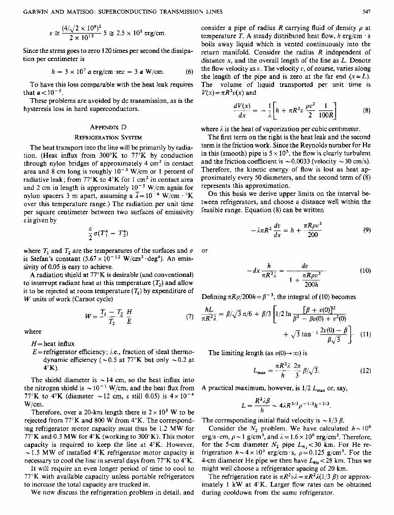
We now discuss the refrigeration problem in detail, and
consider a pipe of radius R carrying fluid of density p at temperature T. A steady distributed heat flow, h erg/cm . s boils away liquid which is vented continuously into the return manifold. Consider the radius R independent of distance x , and the overall length of the line as L. Denote the flow velocity as v . The velocity v , of eourse, varies along the length of the pipe and is zero at the far end ( x = L ) . The volume of liquid transported per unit time is V(x) = nR2v(x) and
where ,I is the heat of vaporization per cubic centimeter. The first term on the right is the heat leak and the second
term is the friction work. Since the Reynolds number for He in this (smooth) pipe is 5 x lo5, the flow is clearly turbulent and the friction coefficient is - 0.0033 (velocity - 30 cm/s). Therefore, the kmetic energy of flow is lost as heat ap- proximately every 50 diameters, and the second term of (8) represents this approximation.
On this basis we derive upper limits on the interval be- tween refrigerators, and choose a distance well within the feasible range. Equation (8) can be written
dv nRpv3 d X 200
- h R Z - = h + -
or
' 200h
Defining nRp/200h = B- 3, the integral of (10) becomes
The limiting length (as v(O)+ co) is
A practical maximum, however, is 1/2 L,, or, say,
The corresponding initial fluid velocity is - 1/3 8. Consider the N2 problem. We have calculated h - I O 6
erg/s. cm, p - 1 g/cm3, and i = 1.6 x lo9 erg/cm3. Therefore, for the 5cm diameter N2 pipe L,,<30 km. For He re- frigeration h - 4 x lo3 erg/cm ' s , p=O.125 g/cm3. For the 4cm diameter He pipe we then have LHe < 28 km. Thus we might well choose a refrigerator spacing of 20 km.
The refrigeration rate is nR2ui = nR2J.( 1/3 B ) or approx- imately 1 kW at 4°K. Larger flow rates can be obtained during cooldown from the same refrigerator.
548 PROCEEDINGS OF THE IEEE, APRIL 1967
Little energy is lost in allowing the N, vapor to warm to 300°K on its return to the refrigerator, since the latent heat of vaporization is roughly equal to the energy required to cool to the boiling point.
With helium, however, precisely the opposite is true, since the latent heat per cubic centimeter is smaller by a factor -60; i.e., most of the energy required to liquefy helium gas goes into cooling the gas to 4°K.
The N2 evaporation rate is - 2 liters per second in 20 km or a gas flow rate at STP of 3000 cfm. We propose to operate at a pressure of 10 atmospheres to decrease the velocity by a factor of ten and to reduce the pumping power.
For He the critical pressure is 2.26 atmospheres; thus, not much over-pressure is permissible. However, the vapor density at 4°K (1 atm) is about 10 per cent of the liquid density. A return pipe at 4°K and ten times the area will then not add much pressure drop and will only double the helium investment (-28 million ft3 He gas STP, costing $2 x lo6 and - 10 percent of the annual production).
Cooling by supercooled N, and He4 has been considered but was found to be much less effective. Superfiuid He (He 11) could be used without pumping but only over much shorter distances.
VACUUM PUMPS
The limiting pumping speed of a pipe (in cm3/s) of diameter D and length L is [20]
c - 1.2 x 1 0 4 ~ 3 ~ - 1
The volume is V = rc/4D2L. Thus the pumping time constant is
V C t = - = 6 x 10⁻⁵L2D-’ seconds.
Thus the pump capacity and pump separation depend upon how rapidly it is desired to pump out the air. For example, since D = 15 cm, if we choose t =200 seconds (or total pumpdown time of - 15 minutes) the pump separa- tion must be - 50 m. The speed of the pumps then must be the volume of line in 50 meters per 200 seconds or 25 l/s. However, if we choose t = 3 hours (a total pumpdown time of - 10 hours) the pump separation can be 500 m with a pumping speed of 5 l/s.
APPENDIX E DIFFERENTIAL EXPANSION
The cryogenics engineer, like hs steamy brother, must reckon with thermal expansion. Ordinary metals on being cooled to 0°K contract - 0.3 percent, some plastics - 2 per- cent. Therefore, upon cooling, a long line fixed at the ends is subjected to a 0.3 percent longitudinal stretch which, with an elastic modulus - 10” dyn/cm2 corresponds to a tension - 3000 atm or 50 000 psi. It is desirable to avoid such stresses in order to eliminate the massive insulating clamps and additional gear required to stretch the line, and in particular to avoid the accompanying heat conduction. It is not impossible to use such techniques, particularly with
low-thermalexpansion materials, but it is desirable to have the possibility of using any reasonable materials in the line. A contraction -0.3 percent on a 20-km- run amounts to - 60 m, which is large. Fortunately, however, it is not neces- sary to allow for differential expansion between the parts of the structure which are at 4°K and 77°K unless very dif- ferent materials are involved. (Even when the materials do have vastly different coefficients of thermal expansion this part of the problem can be solved by the frequent insertion of bellows in the N2 lines of say 0.1 percent or - 50 cm every 500 meters.) Undoubtedly the simplest solution to the prob- lem of the contraction of the cable itself is to twist the super- conducting cables as they are fed into the housing. A twist which increases the length by a few percent will allow (preferably with a compressible center) an extension of 0.5 percent without much cost penalty. Finally, to take care of the absolute contraction of the largediameter housing for the cables and for the helium line, bellows, - 1.5 m long every 500 meters, can be inserted.
REFERENCES [l ] J. G. Howard, “Future availability and cost of electrical energy,”
Iron andsteel Engineer, pp. 204-209, September 1965. [2] L. M. Olmsted, “14th steam-station cost survey,” Electrical World,
pp. 103-118, October 18, 1965. [3] National Power Survey-A Report by the Federal Power Commission.
Washington: U. S. Government Printingoffice, 1964,~. 212. [4] M. G . Benz, “Superconducting properties of diffusion-processed
niobium-tin tape,” Bull. Am. Phys. SOC. II, vol. 11, p p , 108, January 1966.
[SI D. B. Montgomery and W. Sampson, “Measurements on niobium- tin samples in 200-kG continuous fields,” Appl. Phys. Lett., vol. 6, pp. 1 11-1 12, March 1965.
[6] A. R. Kantrowitz and Z. J. J. Stekly, “New principle for the con- struction of stabilized superconducting coils,” Appl. Phys. Lett., vol. . 6, p. 56, February 1965.
[7] National Power Survey, op. cit., p. 156. [8] C. Laverick, “Progress in the development of superconducting
[9] R. B. Scott, Cryogenic Engineering. Princeton, N. J. : Van Nostrand,
[lo] R. McFee, “Optimum input leads for cryogenic apparatus,” Rev.
[ l l ] F. G. Spreadbury, Electronic Rectijcation. Princeton, N. J.: Van
magnets,” Cryogenics, vol. 5, pp. 152-158, June 1965.
1959, pp. 250-251.
Sci. Instr., vol. 30, pp. 98-102, February 1959.
Nostrand, 1962,~. 196. [12] Ibid.,pp. 177-178. [I31 NationalPower Survey, op. cit., p. 157. [14] D. P. Seraphim, F. M. d’Heurle, and W. R. Heller, “Coherent super-
conducting behavior of two metals (AI-Pb) in a synthetic filamentary structure,” Appl. Phys. L e t t . , vol. 1, pp. 93-95, December I , 1962.
[IS] H. E. Cline, B. P. Strauss, R. M. Morse, and J. Wulff, “Supercon- ductivity of a composite of fine niobium wires in copper,” 1. Appl. Phys.,vol. 37,pp. 5-8, January 1966.
[I61 C. P. Bean, R. L. Fleischer, P. S. Swartz, and H. R. Hart, Jr., J . Appl. Phys., vol. 37, pp. 2218-2224, May 1966.
[I71 C. J. Smithells, Metals Reference Book, vol. 11. Washlngton, D. C.: Buttenvorths, 1962, p. 744.
[IS] Yearbook of the American Bureau of Metal Statistics for 1962, New York, 1963, p. 98.
[I91 C. P. Bean et al., “A research investigation of the factors that affect the superconducting properties of materials,” General Electric Re- search and Development Center, Schenectady, N. Y., Tech. Rept. AFML-TR-65431, March 1966.
[20] R. B. Scott, Cryogenic Engineering. Princeton, N. J.: Van Nostrand, 1959, p. 156.
[2l] K. J. R. Wilkinson, “Prospect of- emplaying condu-rs at low temperature in power cables and in power transformers,” Proc. IEE (London), vol. 113, pp. 1509-1521, September 1966.