Submitted to ASME Journal of Computational and Nonlinear … · 2015-12-03 · OMB No. 0704-0188...
46
UNCLASSIFIED: Distribution Statement A. Approved for public release. #26428 This material is declared a work of the U.S. Government and is not subject to copyright protection in the United States. Approved for public release; distribution is unlimited. Submitted to ASME Journal of Computational and Nonlinear Dynamics LAMINATED COMPOSITE SHELL ELEMENT USING ABSOLUTE NODAL COORDINATE FORMULATION AND ITS APPLICATION TO ANCF TIRE MODEL Hiroki Yamashita Department of Mechanical and Industrial Engineering The University of Iowa 2312 Seamans Center Iowa City, IA 52242 Paramsothy Jayakumar US Army TARDEC 6501 E. 11 Mile Road Warren, MI 48397-5000 Hiroyuki Sugiyama Department of Mechanical and Industrial Engineering The University of Iowa 2416C Seamans Center Iowa City, IA 52242 [email protected]
Transcript of Submitted to ASME Journal of Computational and Nonlinear … · 2015-12-03 · OMB No. 0704-0188...
UNCLASSIFIED: Distribution Statement A. Approved for public release. #26428
This material is declared a work of the U.S. Government and is not subject to copyright protection in the United
States. Approved for public release; distribution is unlimited.
Submitted to
ASME Journal of Computational and Nonlinear Dynamics
LAMINATED COMPOSITE SHELL ELEMENT USING ABSOLUTE
NODAL COORDINATE FORMULATION AND ITS APPLICATION TO
ANCF TIRE MODEL
Hiroki Yamashita
Department of Mechanical and Industrial Engineering
The University of Iowa
2312 Seamans Center
Iowa City, IA 52242
Paramsothy Jayakumar
US Army TARDEC
6501 E. 11 Mile Road
Warren, MI 48397-5000
Hiroyuki Sugiyama
Department of Mechanical and Industrial Engineering
The University of Iowa
2416C Seamans Center
Iowa City, IA 52242
Report Documentation Page Form ApprovedOMB No. 0704-0188
Public reporting burden for the collection of information is estimated to average 1 hour per response, including the time for reviewing instructions, searching existing data sources, gathering andmaintaining the data needed, and completing and reviewing the collection of information. Send comments regarding this burden estimate or any other aspect of this collection of information,including suggestions for reducing this burden, to Washington Headquarters Services, Directorate for Information Operations and Reports, 1215 Jefferson Davis Highway, Suite 1204, ArlingtonVA 22202-4302. Respondents should be aware that notwithstanding any other provision of law, no person shall be subject to a penalty for failing to comply with a collection of information if itdoes not display a currently valid OMB control number.
1. REPORT DATE 24 APR 2015 2. REPORT TYPE
3. DATES COVERED 00-00-2015 to 00-00-2015
4. TITLE AND SUBTITLE Laminated Composite Shell Element Using Absolute Nodal Coordinateformulation and its Application to ANCF Tire Model
5a. CONTRACT NUMBER
5b. GRANT NUMBER
5c. PROGRAM ELEMENT NUMBER
6. AUTHOR(S) 5d. PROJECT NUMBER
5e. TASK NUMBER
5f. WORK UNIT NUMBER
7. PERFORMING ORGANIZATION NAME(S) AND ADDRESS(ES) US Army RDECOM-TARDEC,6501 E. 11 Mile Road,Warren,MI,48397-5000
8. PERFORMING ORGANIZATIONREPORT NUMBER
9. SPONSORING/MONITORING AGENCY NAME(S) AND ADDRESS(ES) 10. SPONSOR/MONITOR’S ACRONYM(S)
11. SPONSOR/MONITOR’S REPORT NUMBER(S)
12. DISTRIBUTION/AVAILABILITY STATEMENT Approved for public release; distribution unlimited
13. SUPPLEMENTARY NOTES Submitted to ASME Journal of Computational and Nonlinear Dynamics
14. ABSTRACT See Report
15. SUBJECT TERMS
16. SECURITY CLASSIFICATION OF: 17. LIMITATION OF ABSTRACT Same as
Report (SAR)
18. NUMBEROF PAGES
45
19a. NAME OFRESPONSIBLE PERSON
a. REPORT unclassified
b. ABSTRACT unclassified
c. THIS PAGE unclassified
Standard Form 298 (Rev. 8-98) Prescribed by ANSI Std Z39-18

UNCLASSIFIED: Distribution Statement A. Approved for public release. #26428
This material is declared a work of the U.S. Government and is not subject to copyright protection in the United
States. Approved for public release; distribution is unlimited.
ABSTRACT
In this investigation, a laminated composite shell element of the absolute nodal coordinate
formulation (ANCF) is developed for application to the modeling of fiber-reinforced rubber
(FRR) structure of the physics-based ANCF tire model. The complex deformation coupling
exhibited in fiber-reinforced composite materials can be automatically considered in the shear
deformable laminated composite shell element using the continuum mechanics approach, and the
element lockings are systematically eliminated by the assumed natural strain and enhanced strain
approaches, thereby leading to a locking-free shear deformable ANCF composite shell element.
Furthermore, various nonlinear material models can be considered for each layer in a way same
as solid elements. Using the ANCF composite shell element developed, a physics-based ANCF
tire model is developed by considering the detailed tire geometry and material properties. The
experimental validation of the tire model is conducted for the load-deflection curve to ensure that
the fundamental structural tire properties can be correctly captured in the ANCF tire model.

UNCLASSIFIED: Distribution Statement A. Approved for public release. #26428
1
This material is declared a work of the U.S. Government and is not subject to
copyright protection in the United States. Approved for public release; distribution is unlimited.
1. INTRODUCTION
An accurate modeling of the complex tire geometry and the anisotropic material properties of tire
structure is essential to the tire performance evaluation including the tire contact pressure and the
braking/traction and cornering forces. Since a tire consists of layers of plies and steel belts
embedded in rubber, the tire structure needs to be modeled by cord-rubber composite materials
and various fiber-reinforced rubber material models are proposed for use in detailed finite
element tire models. Since Young’s modulus of the steel cord is significantly higher than that of
the rubber matrix, mechanical property of the fiber-reinforced rubber (FRR) is highly nonlinear
[1]. In particular, the tire cross-section property is of significant importance in characterizing the
normal contact pressure distribution. Furthermore, the in-plane shear deformation of the carcass
contributes to the cornering characteristics of tires. For this reason, high-fidelity finite element
tire models that account for the tire geometric and material nonlinearities are developed and used
for the tire performance evaluation [2,3]. However, existing finite element tire models cannot be
integrated into the vehicle dynamics simulation due to the essential difference in formulations
and solution procedures used in multibody dynamics and nonlinear finite element codes. This
prevents an integration of the high-fidelity tire model into the multibody vehicle dynamics
simulation [4] and, therefore, the structural characteristics of tires and the transient tire dynamics
are, in general, evaluated using different computational models and different simulation
approaches. To overcome this fundamental and essential problem in the tire dynamics simulation,
a tire model based on the flexible multibody dynamics approach [4-6] is developed using the
absolute nodal coordinate formulation (ANCF [7, 8]). The in-plane ANCF-LuGre tire model
developed for the transient braking analysis allows for considering the nonlinear coupling
between the dynamic structural deformation of the tire and its transient tire force in the contact
UNCLASSIFIED: Distribution Statement A. Approved for public release. #26428
2
This material is declared a work of the U.S. Government and is not subject to
copyright protection in the United States. Approved for public release; distribution is unlimited.
patch using general multibody dynamics computer algorithms [6]. The generalization of the in-
plane ANCF tire model to the three-dimensional model requires the development of the new
ANCF shell element suited for the tire model, which allows for modeling the nonlinear fiber-
reinforced rubber materials and the accurate three-dimensional stresses under various
maneuvering scenarios. To this end, the continuum mechanics based shear deformable shell
element of the absolute nodal coordinate formulation (ANCF) [9] is generalized to a laminated
composite shell element in this study for application to the modeling of fiber-reinforced rubber
(FRR) structure of the physics-based ANCF tire model. Furthermore, a physics-based ANCF
structural tire model is developed using the shear deformable laminated composite shell elements.
The paper that discusses the development of the ANCF laminated composite shell element and
the physics-based ANCF structural tire model is organized as follows. In Section 2, the
kinematics and elastic force formulation of the shear deformable ANCF shell element are
overviewed and the procedure for eliminating the element lockings is explained. The classical
lamination theory and the generalization of the ANCF shell element to the laminated composite
shell element are discussed in Section 3. In Section 4, numerical results and comparison with
analytical solutions and existing composite shell elements are presented to validate the ANCF
laminated composite shell element developed in this study. Modeling of the physics-based
ANCF tire model using the ANCF laminated composite shell element is discussed in Section 5,
and comparison with measurement results are presented for validation. Summary and
conclusions drawn from this study are presented in Section 6.
UNCLASSIFIED: Distribution Statement A. Approved for public release. #26428
3
This material is declared a work of the U.S. Government and is not subject to
copyright protection in the United States. Approved for public release; distribution is unlimited.
2. CONTINUUM MECHANICS BASED SHEAR DEFORMABLE ANCF SHELL
ELEMENT
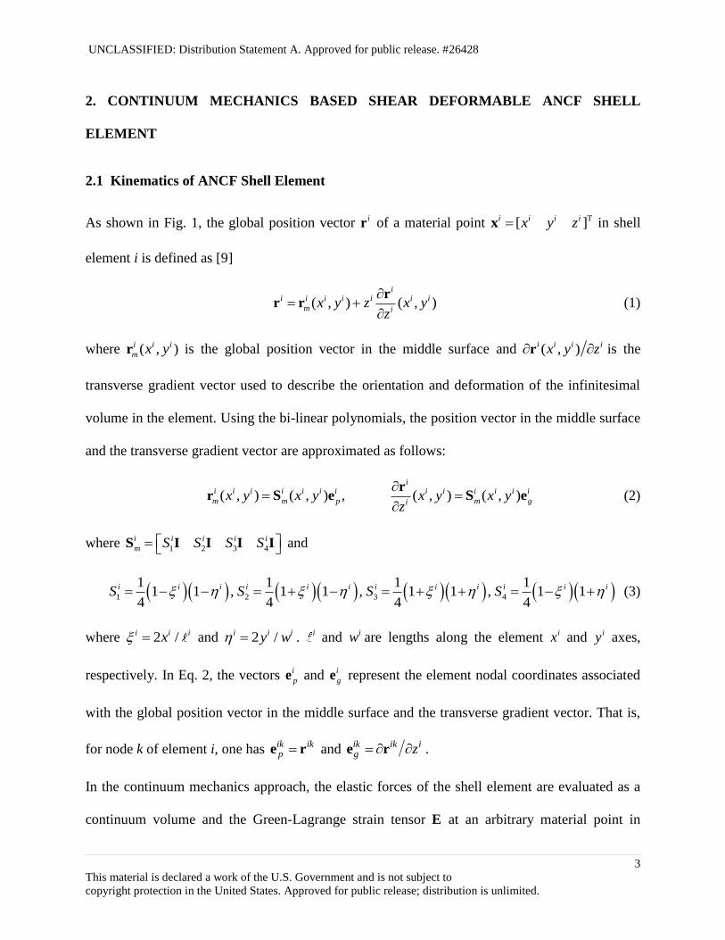
2.1 Kinematics of ANCF Shell Element
As shown in Fig. 1, the global position vector ir of a material point T[ ]i i i ix y zx in shell
element i is defined as [9]
( , ) ( , )i
i i i i i i i
m ix y z x y
z
rr r (1)
where ( , )i i i
m x yr is the global position vector in the middle surface and ( , )i i i ix y z r is the
transverse gradient vector used to describe the orientation and deformation of the infinitesimal
volume in the element. Using the bi-linear polynomials, the position vector in the middle surface
and the transverse gradient vector are approximated as follows:
( , ) ( , ) , ( , ) ( , )i
i i i i i i i i i i i i i
m m p m gix y x y x y x y
z
rr S e S e (2)
where 1 2 3 4
i i i i i
m S S S S S I I I I and
1 2 3 4
1 1 1 11 1 , 1 1 , 1 1 , 1 1
4 4 4 4
i i i i i i i i i i i iS S S S (3)
where 2 /i i ix and 2 /i i iy w . i and iw are lengths along the element ix and iy axes,
respectively. In Eq. 2, the vectors i
pe and i
ge represent the element nodal coordinates associated
with the global position vector in the middle surface and the transverse gradient vector. That is,
for node k of element i, one has ik ikp e r and
ik ik ig z e r .
In the continuum mechanics approach, the elastic forces of the shell element are evaluated as a
continuum volume and the Green-Lagrange strain tensor E at an arbitrary material point in

UNCLASSIFIED: Distribution Statement A. Approved for public release. #26428
4
This material is declared a work of the U.S. Government and is not subject to
copyright protection in the United States. Approved for public release; distribution is unlimited.
element i is defined as follows:
1
( )2
i i T i E F F I (4)
where iF is the global position vector gradient tensor. The preceding equation can be expressed
in terms of the covariant strain tensor iE as
1( ) ( )i i T i i E J E J (5)
where i i i J X x and iX represents the global position vector of element i at an arbitrary
reference configuration. The covariant strain tensor is defined as
1
( ) ( )2
i i T i i T i E J J J J (6)
where i i i J r x . Using Eq. 5, the strain vector [ ]i i i i i i i T
xx yy xy zz xz yz ε is
defined as
( )i i T iε T ε (7)
where iε is the covariant strain vector obtained by Eq. 6, and the constant transformation matrix
iT is as given in literature [9].
2.2 Generalized Elastic Forces
In the continuum mechanics based shear deformable ANCF shell element, element lockings
occur due to the use of low-order polynomials, thereby resulting in overly stiff bending behavior.
The locking in the bi-linear shear deformable ANCF shell element includes the transverse shear
locking; Poisson’s thickness locking; curvature thickness locking; in-plane shear locking [9, 10].
These lockings are systematically alleviated by applying the assumed natural strain method [11,
12] and the enhanced assumed strain method [13, 14]. The enhanced strain field for the
continuum mechanics-based shear deformable ANCF shell element can then be defined as
UNCLASSIFIED: Distribution Statement A. Approved for public release. #26428
5
This material is declared a work of the U.S. Government and is not subject to
copyright protection in the United States. Approved for public release; distribution is unlimited.
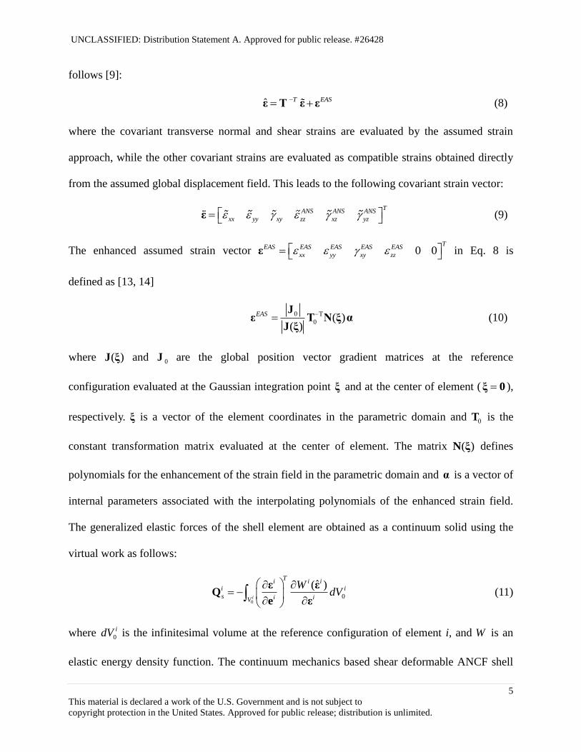
follows [9]:
ˆ T EAS ε T ε ε (8)
where the covariant transverse normal and shear strains are evaluated by the assumed strain
approach, while the other covariant strains are evaluated as compatible strains obtained directly
from the assumed global displacement field. This leads to the following covariant strain vector:
TANS ANS ANS
xx yy xy zz xz yz ε (9)
The enhanced assumed strain vector 0 0T
EAS EAS EAS EAS EAS
xx yy xy zz ε in Eq. 8 is
defined as [13, 14]
0 T
0 ( )( )
EAS J
ε T N ξ αJ ξ
(10)
where )(ξJ and 0J are the global position vector gradient matrices at the reference
configuration evaluated at the Gaussian integration point ξ and at the center of element ( 0ξ ),
respectively. ξ is a vector of the element coordinates in the parametric domain and 0T is the
constant transformation matrix evaluated at the center of element. The matrix ( )N ξ defines
polynomials for the enhancement of the strain field in the parametric domain and α is a vector of
internal parameters associated with the interpolating polynomials of the enhanced strain field.
The generalized elastic forces of the shell element are obtained as a continuum solid using the
virtual work as follows:
00
ˆ( )i
Ti i i
i i
s i iV
WdV
ε εQ
e ε (11)
where 0
idV is the infinitesimal volume at the reference configuration of element i, and W is an
elastic energy density function. The continuum mechanics based shear deformable ANCF shell

UNCLASSIFIED: Distribution Statement A. Approved for public release. #26428
6
This material is declared a work of the U.S. Government and is not subject to
copyright protection in the United States. Approved for public release; distribution is unlimited.
element allows for considering general hyperelasticity material models in a way same as existing
solid elements.
3. LAMINATED COMPOSITE SHELL FORMULATION
In fiber-reinforced composite materials that are widely used in many engineering applications,
laminae having different fiber angles are bonded together to produce desired material properties.
Since many laminae are stacked at different fiber angles, the complex deformation coupling
between the extension, shearing, bending and twisting occurs, and such a deformation coupling
characterizes the mechanical behavior of fiber-reinforced composite materials [15]. In the first
part of this section, the macro-mechanical behavior of fiber-reinforced composite materials is
overviewed using the classical lamination theory.
3.1 Classical Lamination Theory
In the Kirchhoff plate theory, the plane stress is assumed and the in-plane strains of a plate
[ ]T
p xx yy xy ε are defined as
0
p p z ε ε κ (12)
where 0 0 0 0[ ]T
p xx yy xy ε is a vector of the in-plane strains in the middle plane, and
[ ]T
x y xy κ is a curvature vector associated with bending and twisting. Using a linear
orthotropic constitutive law for a fiber-reinforced plate, the in-plane stress vector is related to its
strain vector by p p pσ C ε , and the material moduli is given as [15]
1 T
p p
C R C R (13)
In the preceding equation, the transformation matrix R is a function of the fiber angle that
defines the orientation of the fiber coordinate system o-12 with respect to the material frame o-xy

UNCLASSIFIED: Distribution Statement A. Approved for public release. #26428
7
This material is declared a work of the U.S. Government and is not subject to
copyright protection in the United States. Approved for public release; distribution is unlimited.
of the plate as shown in Fig. 1. This matrix is defined by
2 2
2 2
cos sin sin 2
sin cos sin 2
sin 2 sin 2 cos 2
R (14)
and pC is the material moduli of an orthotropic material in the fiber coordinate system as
1111 1122
1122 2222
1212
0
0
0 0
p
C C
C C
C
C (15)
where 1111
1 12 21(1 )C E , 2222
2 12 21(1 )C E , 1122
21 1 12 21(1 )C E , and 1212
12C G .
While the coupling terms between the normal and shear strains in the fiber coordinate system are
zero as observed in Eq. 15, the extension and shear coupling occurs for the stress and strain field
defined in the material frame and the coupling terms in the material moduli matrix pC of Eq. 13
are not zero. That is, a plate subjected to a uniaxial load produces in-plane shear deformation due
to the extension and shear coupling [15]. Using the linear constitutive law for an orthotropic
material, the in-plane stresses of a lamina are defined as
0
p p p pz σ C ε C κ (16)
The force and moment resultants of a fiber-reinforced composite consisting of N orthotropic
laminae can then be defined as
1 1
0
1 1
k k
k k
N Nz zk k
p p pz z
k k
dz z dz
N C ε C κ (17)
and
1 1
0 2
1 1
k k
k k
N Nz zk k
p p pz z
k k
z dz z dz
M C ε C κ (18)
where [ ]T
x y xyN N NN , [ ]T
x y xyM M MM , k
pC is the material moduli matrix of the k-

UNCLASSIFIED: Distribution Statement A. Approved for public release. #26428
8
This material is declared a work of the U.S. Government and is not subject to
copyright protection in the United States. Approved for public release; distribution is unlimited.
th layer, and kz is the thickness coordinate at the upper surface of the k-th layer. It is important to
notice here that the force and moment resultants are defined as forces and moments per unit
length [15]. Since the strain and curvature are not function of the thickness coordinate z in the
Kirchhoff plate theory, Eqs. 17 and 18 are written in a matrix form as [15]
0
p
N A B ε
M B D κ (19)
where 1
1
( ) ( )N
k
ij p ij k k
k
A C z z
, 2 2
1
1
( ) ( ) / 2N
k
ij p ij k k
k
B C z z
, and 3 3
1
1
( ) ( ) / 3N
k
ij p ij k k
k
D C z z
.
The presence of the matrix B implies the extension and bending/twisting coupling of a laminate.
However, if each lamina above the mid-plane is identical to that below the mid-plane in both
geometry and material properties (i.e., the laminate is mid-plane symmetric), the matrix B
becomes identically zero (i.e., 0ijB ) and the extension and bending/twisting coupling vanishes.
It is important to notice here that the extension and shear coupling still exists. Another important
case is a balanced laminate, in which a laminate consists of a pair of laminae that have opposite
fiber angles ( and ) above and below the mid-plane, regardless of the stacking sequence.
This eliminates the extension and shear coupling. That is, coupling terms of in-plane normal and
in-plane shear strains in matrix A are identically zero. For a two-layer laminate with the same
layer thickness and opposite fiber angle ( / ) about the mid-plane, the extension and shear
coupling vanishes, but the extension and twisting coupling in B matrix exists. This causes
twisting deformation of a laminated composite plate subjected to a uniaxial tensile loading [15].
The presence of such a complex coupling is discussed using the ANCF laminated composite
shell element in Section 4.

UNCLASSIFIED: Distribution Statement A. Approved for public release. #26428
9
This material is declared a work of the U.S. Government and is not subject to
copyright protection in the United States. Approved for public release; distribution is unlimited.
3.2 Generalization to Shear Deformable ANCF Composite Shell Element
As discussed in Section 2, the continuum mechanics based ANCF shell element is formulated as
a continuum solid that accounts for the three-dimensional stress state, thus the complex
deformation coupling exhibited in laminates can be automatically considered without special
elastic force formulations. That is, the generalized elastic force of the laminated composite shell
element that consists of N layers can be defined as follows:
00
1
ˆ( )ik
Tik ik ikN
i ik
s i ikVk
WdV
ε εQ
e ε (20)
In the preceding equation, the integration interval for the k-th layer in the thickness direction is
from 1kz to kz . In other words, the element generalized elastic forces are evaluated layer by
layer and the resulting generalized elastic forces of each layer are simply added together to
define the elastic force vector of the laminated composite shell. It is important to notice here that
there is no restriction in material models considered in each lamina, despite the fact the
orthotropic material law is the most popular material model used for reinforced composite
materials. Two Gaussian integration points are used along the thickness when the elastic forces
of each layer are evaluated.
Orthotropic Saint-Venant-Kirchhoff Material Model For an orthotropic Saint-Venant-
Kirchhoff material, the material moduli 2 /ijkl
ij klC W of a fiber-reinforced lamina in the
material frame is defined as [16]
( )( )( )( )ijkl i j k l abcd
a b c dC C b a b a b a b a (21)
where 1 1 2 3( ) [ ]i J b b b and abcdC is the tangent material moduli defined using 9 material
parameters in the fiber coordinate system 1 2 3[ ]a a a as shown in Fig. 1, where the direction of
UNCLASSIFIED: Distribution Statement A. Approved for public release. #26428
10
This material is declared a work of the U.S. Government and is not subject to
copyright protection in the United States. Approved for public release; distribution is unlimited.
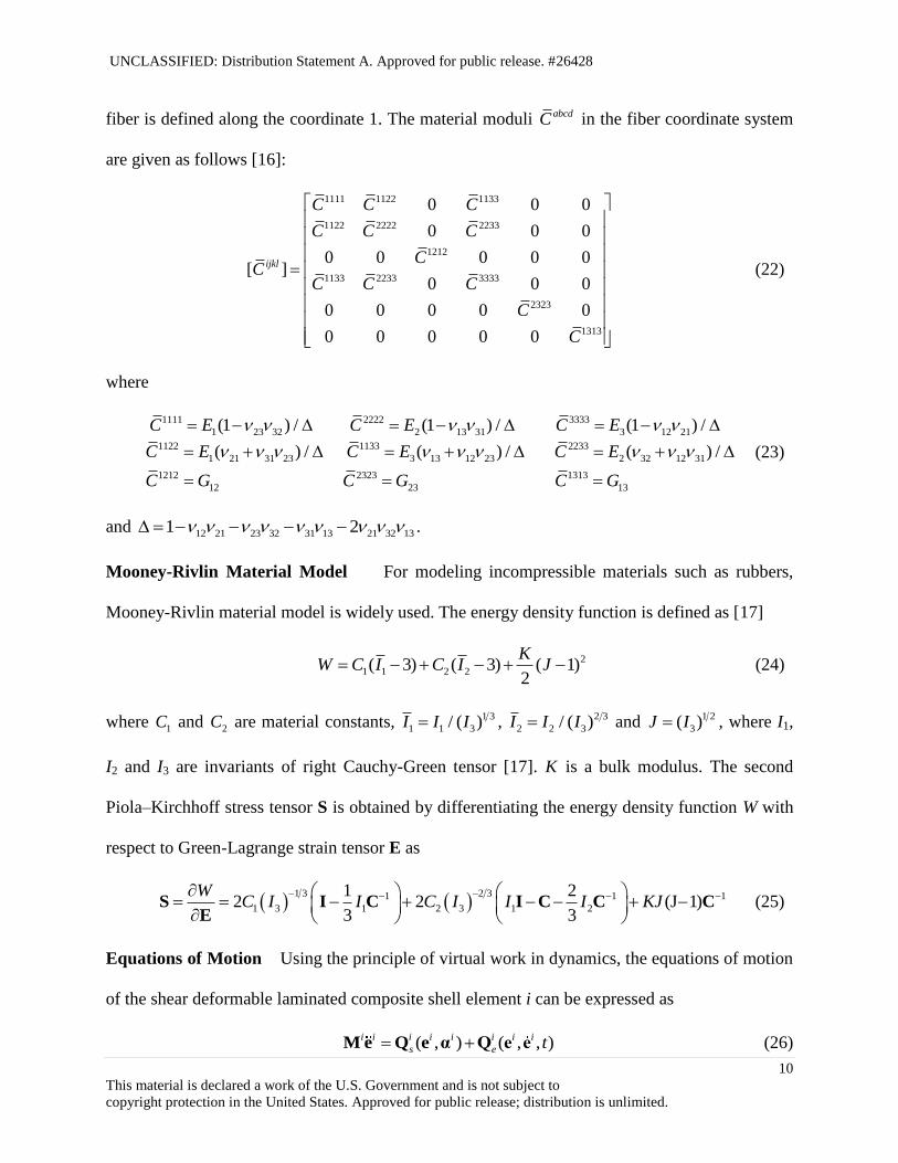
fiber is defined along the coordinate 1. The material moduli abcdC in the fiber coordinate system
are given as follows [16]:
1111 1122 1133
1122 2222 2233
1212
1133 2233 3333
2323
1313
0 0 0
0 0 0
0 0 0 0 0[ ]
0 0 0
0 0 0 0 0
0 0 0 0 0
ijkl
C C C
C C C
CC
C C C
C
C
(22)
where
1111 2222 3333
1 23 32 2 13 31 3 12 21
1122 1133 2233
1 21 31 23 3 13 12 23 2 32 12 31
1212 2323 1313
12 23 13
(1 ) / (1 ) / (1 ) /
( ) / ( ) / ( ) /
C E C E C E
C E C E C E
C G C G C G
(23)
and 12 21 23 32 31 13 21 32 131 2 .
Mooney-Rivlin Material Model For modeling incompressible materials such as rubbers,
Mooney-Rivlin material model is widely used. The energy density function is defined as [17]
2
1 1 2 2( 3) ( 3) ( 1)2
KW C I C I J (24)
where 1C and 2C are material constants, 1 3
1 1 3/ ( )I I I , 2 3
2 2 3/ ( )I I I and 1 2
3( )J I , where I1,
I2 and I3 are invariants of right Cauchy-Green tensor [17]. K is a bulk modulus. The second
Piola–Kirchhoff stress tensor S is obtained by differentiating the energy density function W with
respect to Green-Lagrange strain tensor E as
1 3 2 31 1 1
1 3 1 2 3 1 2
1 22 2 (J 1)
3 3
WC I I C I I I KJ
S I C I C C CE
(25)
Equations of Motion Using the principle of virtual work in dynamics, the equations of motion
of the shear deformable laminated composite shell element i can be expressed as
( , ) ( , , )i i i i i i i i
s e t M e Q e α Q e e (26)

UNCLASSIFIED: Distribution Statement A. Approved for public release. #26428
11
This material is declared a work of the U.S. Government and is not subject to
copyright protection in the United States. Approved for public release; distribution is unlimited.
where vectors i
sQ and i
eQ are, respectively, the element elastic and external force vectors; and
the matrix iM is the constant element mass matrix defined by
0
0 0
1
( )ik
Ni ik i T i ik
Vk
dV
M S S (27)
where 0ik is the material density of k-th layer at the reference configuration. The internal
parameters iα introduced for the enhanced assumed strains are determined by solving the
following equations [13, 14]:
00
ˆ( )i
TEAS i i
i
i iV
WdV
ε ε0
α ε (28)
It is important to notice here that the preceding equations can be solved at element level for the
unknown internal parameters iα using the procedure presented in the literature [9].
4. NUMERICAL EXAMPLES
4.1 Extension and In-Plane Shear Coupling of Fiber-Reinforced Plate Subjected to
Uniaxial Tensile Load
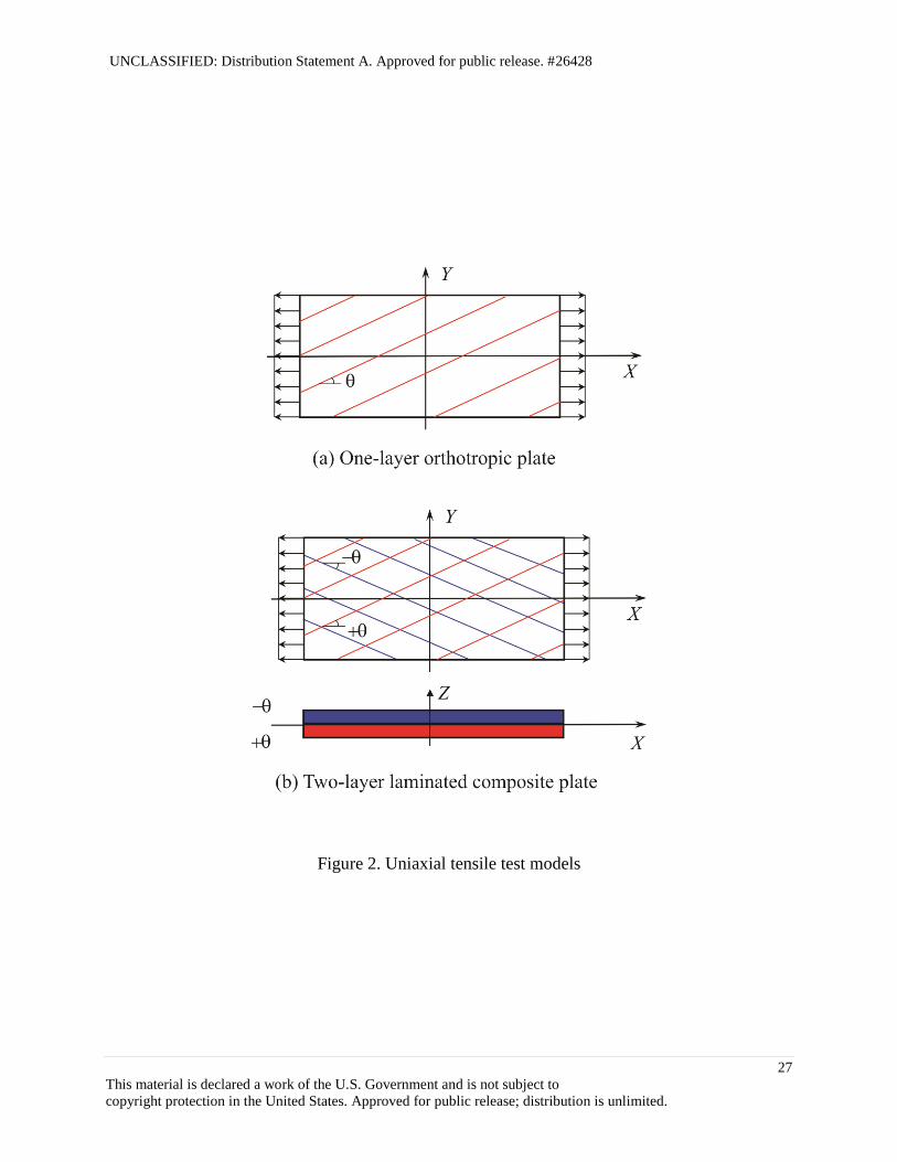
To discuss the extension and in-plane shear coupling of a fiber-reinforced material, a uniaxial
tension test as shown in Fig 2(a) is considered using the shear deformable ANCF shell element.
The length, width and thickness of the plate are 2.0 m, 1.0 m, and 0.01 m, respectively. Young’s
modulus of the fiber and those of the matrix are, respectively, assumed to be 111.8 10xE Pa
and 71.3333 10y zE E Pa. The shear modulus of rigidity and Poisson’s ratio are assumed to
be 6G G 3.33333 10 Paxy xz yzG and 0.4xy xz yz , respectively. The tensile
distributed uniaxial load of 5000 N/m is applied in the X direction. The in-plane shear strain of
UNCLASSIFIED: Distribution Statement A. Approved for public release. #26428
12
This material is declared a work of the U.S. Government and is not subject to
copyright protection in the United States. Approved for public release; distribution is unlimited.
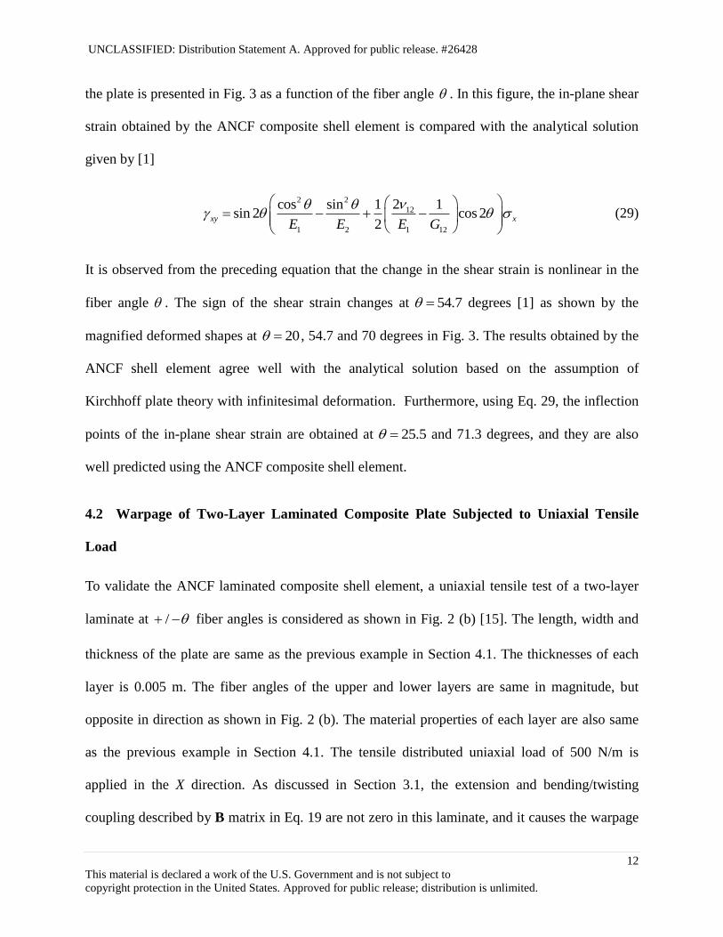
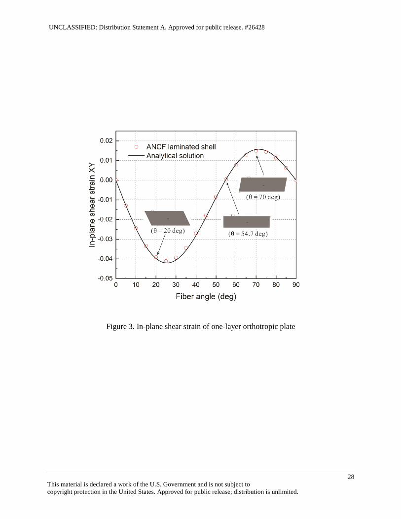
the plate is presented in Fig. 3 as a function of the fiber angle . In this figure, the in-plane shear
strain obtained by the ANCF composite shell element is compared with the analytical solution
given by [1]
2 2
12
1 2 1 12
2cos sin 1 1sin 2 cos 2
2xy x
E E E G
(29)
It is observed from the preceding equation that the change in the shear strain is nonlinear in the
fiber angle . The sign of the shear strain changes at 54.7 degrees [1] as shown by the
magnified deformed shapes at 20 , 54.7 and 70 degrees in Fig. 3. The results obtained by the
ANCF shell element agree well with the analytical solution based on the assumption of
Kirchhoff plate theory with infinitesimal deformation. Furthermore, using Eq. 29, the inflection
points of the in-plane shear strain are obtained at 25.5 and 71.3 degrees, and they are also
well predicted using the ANCF composite shell element.
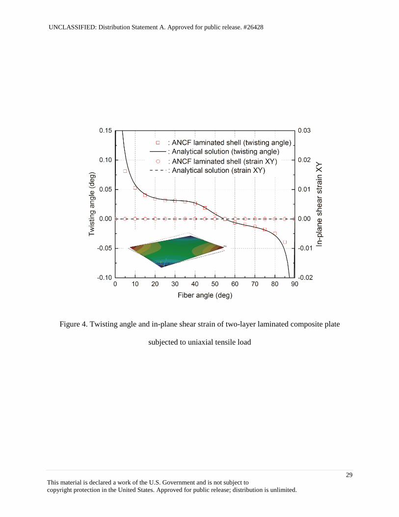
4.2 Warpage of Two-Layer Laminated Composite Plate Subjected to Uniaxial Tensile
Load
To validate the ANCF laminated composite shell element, a uniaxial tensile test of a two-layer
laminate at / fiber angles is considered as shown in Fig. 2 (b) [15]. The length, width and
thickness of the plate are same as the previous example in Section 4.1. The thicknesses of each
layer is 0.005 m. The fiber angles of the upper and lower layers are same in magnitude, but
opposite in direction as shown in Fig. 2 (b). The material properties of each layer are also same
as the previous example in Section 4.1. The tensile distributed uniaxial load of 500 N/m is
applied in the X direction. As discussed in Section 3.1, the extension and bending/twisting
coupling described by B matrix in Eq. 19 are not zero in this laminate, and it causes the warpage

UNCLASSIFIED: Distribution Statement A. Approved for public release. #26428
13
This material is declared a work of the U.S. Government and is not subject to
copyright protection in the United States. Approved for public release; distribution is unlimited.
(twisting) under the uniaxial tensile loading [15]. The extension and shear coupling exists in each
lamina. However, shear deformation of the upper and lower layers caused by the uniaxial tensile
load are same in magnitude, but opposite in direction. Thus, the shear deformations of both
layers are canceled out and no in-plane shearing occurs in the laminated composite. That is, the
extension and shear coupling term of A matrix of the laminate in Eq. 19 becomes identically zero
in this problem.
To demonstrate this fundamental coupling behavior of the laminated composite material using
the ANCF laminated composite shell element, the twisting angle and the in-plane shear strain of
the two-layer laminated composite plate are presented in Fig. 4 as a function of the fiber angle .
In this figure, results obtained by the ANCF laminated composite shell element are compared
with the analytical model based on the classical lamination theory discussed in Section 3.1. In
the analytical model, the warpage is defined by [15]
2 21
2x y xyw x y xy (30)
where the curvature vector [ ]T
x y xy κ is determined by solving the following equation:
10
p
A B Nε
B D Mκ (31)
for [ 0 0]T
xNN and [0 0 0]TM . It is observed from Fig. 4 that the twisting angles
agree well with those based on the classical lamination theory, and the warpage developed by the
uniaxial tensile load applied to the two-layer laminated composite plate is well predicted by the
ANCF laminated composite shell element developed in this study. The sign of the twisting angle
of the composite plate changes at the fiber angle of 54.7 degrees [1], and this important fiber
angle is also correctly predicted with the ANCF laminated composite shell element. Furthermore,
UNCLASSIFIED: Distribution Statement A. Approved for public release. #26428
14
This material is declared a work of the U.S. Government and is not subject to
copyright protection in the United States. Approved for public release; distribution is unlimited.
zero in-plane shear strain is ensured in the results obtained by the ANCF laminated composite
shell element regardless of the fiber angle, and this result agrees with that of the analytical model
based on the classical lamination theory.
4.3 Cantilevered Two-Layer Composite Shell Subjected to a Point Load
To demonstrate the accuracy of the ANCF composite shell element for large deformation
problem of initially curved shell structures, a cantilevered quarter cylinder modeled by /
two-layer composite shell is considered as shown in Fig. 5. The fiber angle of each layer is
assumed to be 20 . The radius of curvature is assumed to be 1.0 m. The width and height are
assumed to be 1.0 m and 0.01 m (i.e., 0.005 m thickness for each layer). Young’s modulus of the
fiber and those of the matrix are, respectively, assumed to be 82.0 10xE Pa and
81.0 10y zE E Pa. The shear modus of rigidity and Poisson’s ratio are assumed to be
7G G 3.84615 10xy xz yzG Pa and 0.3xy xz yz , respectively. The vertical point load
of 10 N is applied to the corner of the shell as shown in Fig. 5. The deformed shape at the static
equilibrium state is shown in Fig. 5, in which the large deformation is exhibited. The static
deflections of the load application point obtained by the ANCF laminated composite shell
element are compared with those of the shear deformable composite shell element of ANSYS
(SHELL181) [17] in Table 1 for different number of elements. It is demonstrated in this Table
that good agreements in solution are obtained between the shear deformable laminated composite
shell elements obtained by the absolute nodal coordinate formulation and the MITC shell
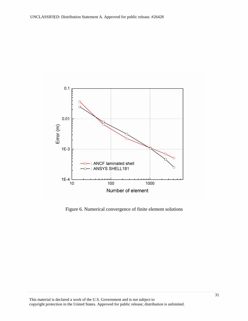
formulation [17] implemented in ANSYS. The numerical convergence of the finite element
solutions are presented in Fig. 6 for errors defined by the deviation from the reference solution,
where the reference solution of -0.80517 m is obtained by 100 100 elements using the ANSYS
UNCLASSIFIED: Distribution Statement A. Approved for public release. #26428
15
This material is declared a work of the U.S. Government and is not subject to
copyright protection in the United States. Approved for public release; distribution is unlimited.
SHELL181 composite shell element. It is observed from this figure that the ideal linear rate of
convergence is ensured in both models for the large deformation problem and it indicates that
element lockings are properly eliminated in the ANCF laminated composite shell element
developed in this study.
4.4 Natural Frequencies of Laminated Composite Plate
The eigenfrequency analysis of the / two-layer composite plate is considered in this
example. The fiber angle of each layer is assumed to be 20 . A free boundary condition is
assumed. The length, width and thickness of the plate are 1.0 m, 1.0 m, and 0.01 m (i.e., 0.005 m
thickness for each layer), respectively. Young’s modulus of the fiber and those of the matrix are,
respectively, assumed to be 76.0 10xE Pa and 73.0 10y zE E Pa. The shear modus of
rigidity and Poisson’s ratio are assumed to be 7G G 1.1538 10xy xz yzG Pa and
0.3xy xz yz , respectively. The material density is assumed to be 500 kg/m3. The first ten
eigenfrequencies and their mode shapes are shown in Table 2 and Fig. 7, respectively. The
eignfrequencies are compared with the reference solutions obtained by the 100 100 elements
using the ANSYS SHELL181 composite shell element. The eigenfrequencies are also well
predicted with the ANCF laminated composite shell element.
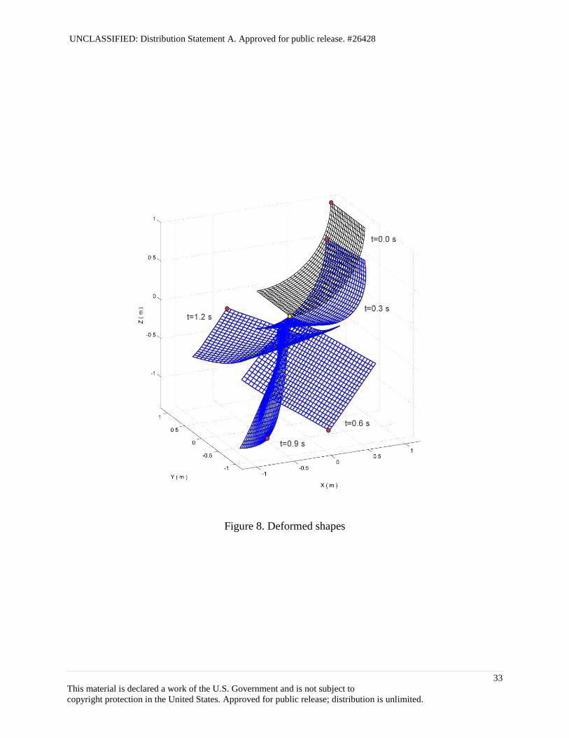
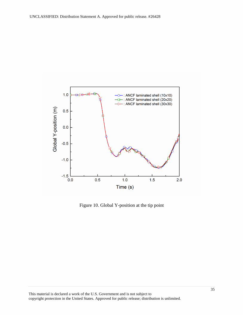
4.5 Quarter Cylinder Pendulum with Laminated Composite Material
In the last numerical example, the nonlinear dynamic analysis of the / two-layer laminated
composite shell structure (a quarter cylinder pendulum) is discussed as shown in Fig. 8. The
radius of curvature is assumed to be 1.0 m. The fiber angle of each layer is assumed to be 20
and the material property of each layer is same as that of the previous example in Section 4.4.
UNCLASSIFIED: Distribution Statement A. Approved for public release. #26428
16
This material is declared a work of the U.S. Government and is not subject to
copyright protection in the United States. Approved for public release; distribution is unlimited.
One corner of the composite quarter cylinder is connected to the ground by a spherical joint. The
deformed shapes under the effect of gravity are shown in Fig. 8, in which large deformation is
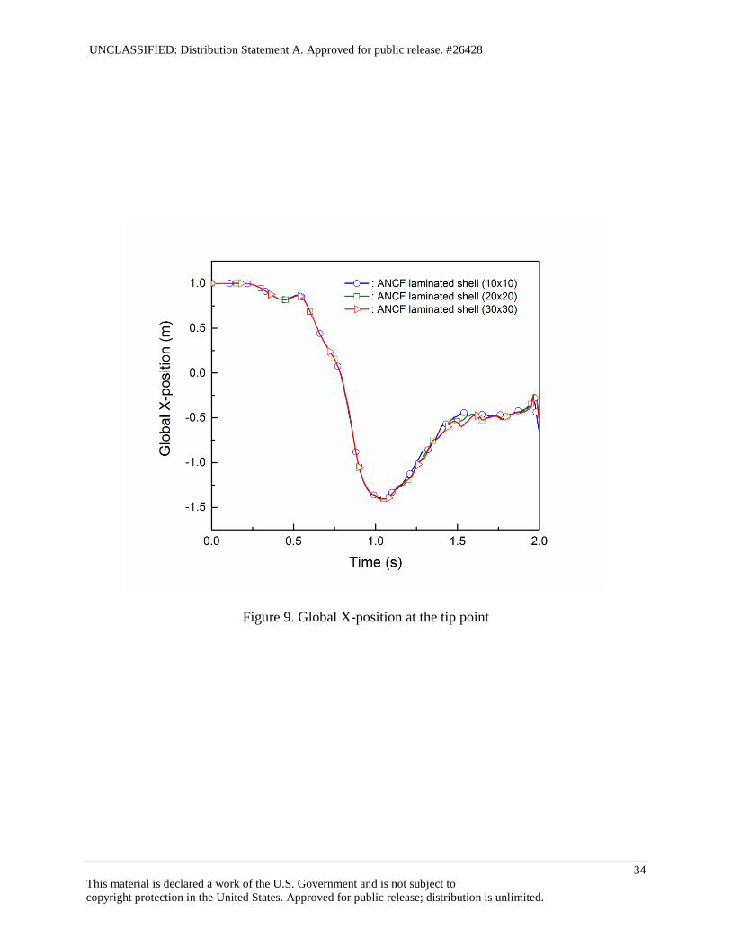
observed. The global X, Y and Z positions at the corner point shown by a red circle in Fig. 8 are
presented in Figs. 9, 10 and 11, respectively. Despite the highly nonlinear dynamics problem
involving the large deformation of composite materials, the numerical solution obtained by
10 10 elements are close to those of 30 30 elements.
5. APPLICATION TO PHYSICS-BASED ANCF TIRE MODEL
In the numerical examples in the preceding section, the fundamental element performance of the
shear deformable ANCF laminated composite shell element developed in this study is
demonstrated. Use of the element developed allows for predicting the complex deformation
coupling between the extension, shearing, bending and twisting that characterizes the mechanical
behavior of fiber-reinforced composite materials. This is an important modeling requirement for
developing the physics-based tire model, and use of the absolute nodal coordinate formulation in
modeling the tire structure allows for the integration of the flexible tire model into the general
multibody dynamics computer algorithms for vehicle dynamics simulation. For this reason, in
this section, a modeling procedure of the physics-based ANCF tire model using the ANCF
laminated composite shell element is discussed, and the fundamental structural characteristics of
the ANCF tire model are validated by comparison with the measurement results of a tire.
A tire has a complex structure that consists of layers of plies and steel belts that are embedded in
rubber, thus an accurate modeling of the complex tire geometry and the anisotropic material
properties is essential to the tire performance evaluation including the tire contact pressure and
the braking/traction and cornering forces. While the in-plane tire belt deformation can be
modeled by an equivalent material model [5,6], such a simplified material model cannot be used

UNCLASSIFIED: Distribution Statement A. Approved for public release. #26428
17
This material is declared a work of the U.S. Government and is not subject to
copyright protection in the United States. Approved for public release; distribution is unlimited.
for predicting the overall tire structural deformation in the three-dimensional analysis. This is
attributed to the fact that the tire section property in both geometry and material is of crucial
importance in characterizing the contact pressure distribution. This necessitates various fiber-
reinforced rubber material models that can be integrated into high-fidelity finite element tire
models [2,3]. However, despite the fact that accurate solutions can be obtained using existing
finite element tire models, difficulties arise when they are integrated into the vehicle dynamics
simulation due to the essential difference in formulations and solution procedures used in
multibody dynamics and nonlinear finite element codes. This prevents an integration of the high-
fidelity tire model into the multibody vehicle dynamics simulation.
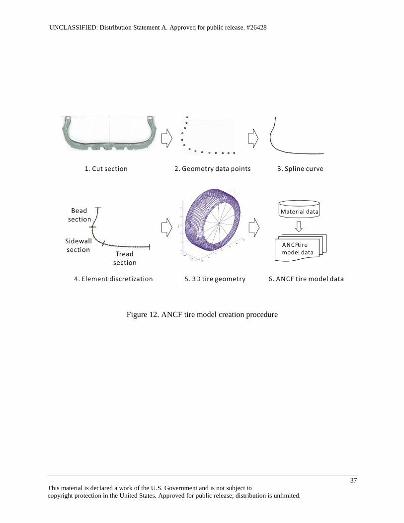
In order to develop a physics-based absolute nodal coordinate formulation tire model, the tire
cross section geometry is imported from the tire cut section and data points are interpolated by a
cubic smoothing spline to extract the nodal position and slope coordinates. As shown in Fig. 12,
the tire cross-section is divided into the tread, sidewall, and bead sections. The number of layers,
cord angles of layers, material properties are provided in each section to create the tire model
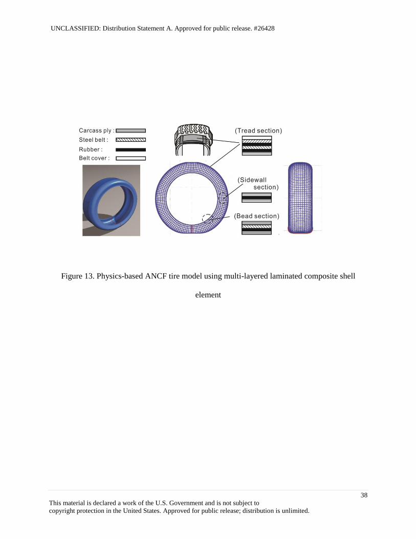
data as shown in Fig. 13. The tread section consists of a carcass ply, two steel belts, a belt cover,
and tread blocks. The carcass ply and steel belt are modeled as an orthotropic material with
polyester and steel cords embedded in rubber, respectively. A rubber layer is considered between
the upper and lower steel belts and between the carcass ply and the lower steel belt. The sidewall
section is modeled by two carcass plies and a rubber that lies in between. The bead section is
modeled by two carcass plies, a steel belt, and a rubber as shown in Fig. 13. Having determined
the cross-section property, the three-dimensional tire geometry is generated by rotating the tire
section model, and the nodal position and slope coordinates of the ANCF tire model are created
as summarized in Fig. 12.
UNCLASSIFIED: Distribution Statement A. Approved for public release. #26428
18
This material is declared a work of the U.S. Government and is not subject to
copyright protection in the United States. Approved for public release; distribution is unlimited.
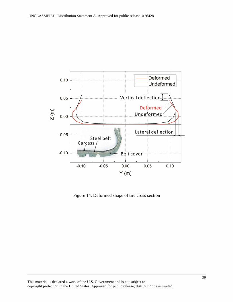
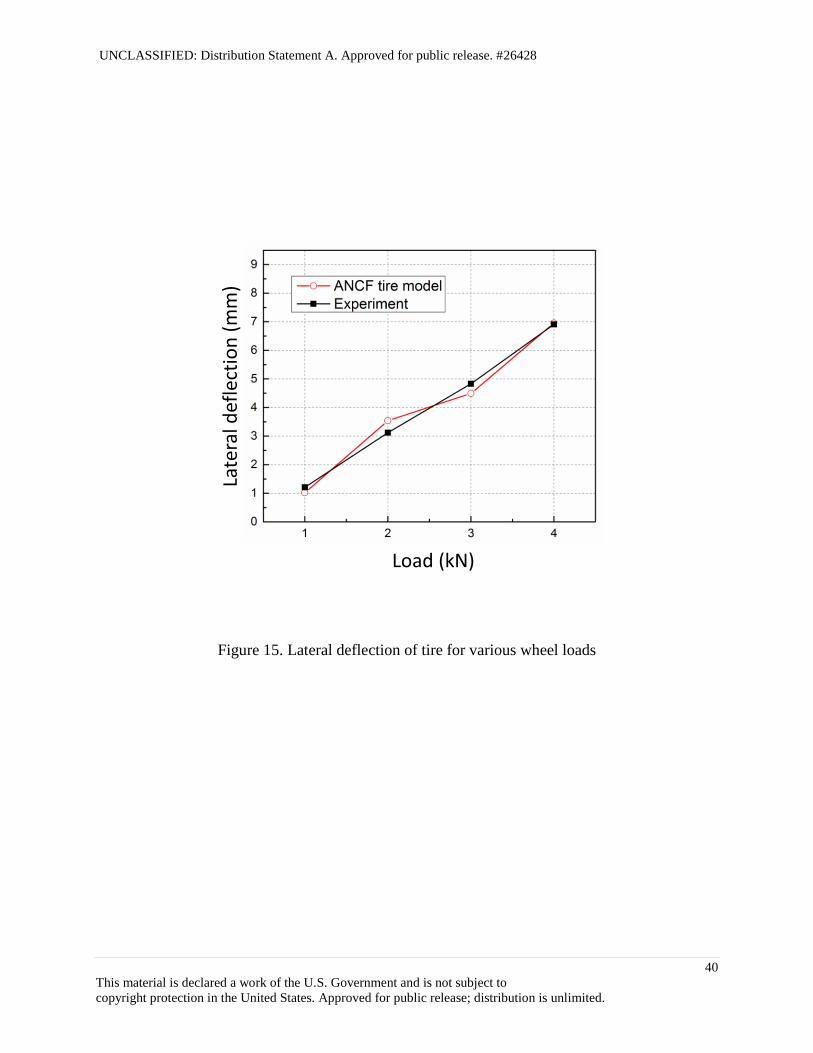
The tire considered in the numerical example is 215/45R17. The air pressure of 220 kPa is
considered by the normal distributed load applied to the inner surface of the tire. The penalty
approach is used for modeling the normal contact force at each node in contact. The load-
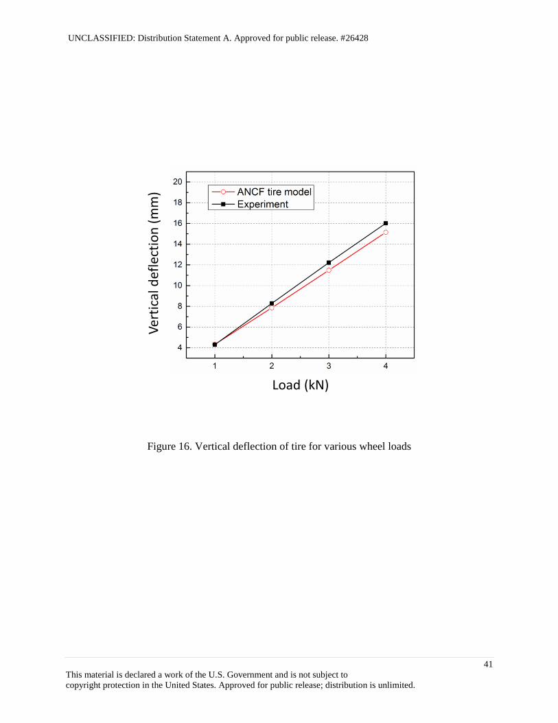
deflection curve is important for characterizing the fundamental structural properties of tires. The
lateral and vertical deflections of the ANCF tire model shown in Fig. 14 are compared with the
measurement results in Figs. 15 and 16. It is observed from these figures that the local tire
deflections are well predicated in both lateral and vertical directions for the various wheel loads.
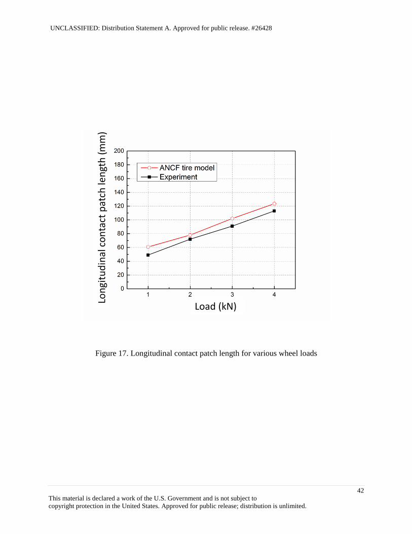
Furthermore, the lengths of the contact patch in the longitudinal and lateral directions also agree
well with those of the measurement results as shown in Fig. 17 and 18.
6. SUMMARY AND CONCLUSIONS
In this study, a continuum mechanics based shear deformable shell element of the absolute nodal
coordinate formulation (ANCF) is generalized to a laminated composite shell element for
application to the modeling of fiber-reinforced rubber (FRR) structure of the physics-based
ANCF tire model. It is shown that the complex deformation coupling exhibited in fiber-
reinforced composite materials can be automatically considered in the shear deformable
laminated composite shell element using the continuum mechanics approach. Furthermore, the
element lockings are systematically eliminated by the assumed natural strain and enhanced strain
approaches, thereby leading to a locking-free shear deformation ANCF laminated composite
shell element. The several benchmark problems are used to validate the ANCF laminated
composite shell element with particular emphasis on the deformation coupling exhibited in
composite materials. The numerical results are in good agreement with those predicated by the
analytical model based on the classical lamination theory and the laminated solid shell element in
ANSYS. Furthermore, using the ANCF laminated composite shell element developed, a physics-

UNCLASSIFIED: Distribution Statement A. Approved for public release. #26428
19
This material is declared a work of the U.S. Government and is not subject to
copyright protection in the United States. Approved for public release; distribution is unlimited.
based ANCF tire model is developed by considering the detailed tire geometry and anisotropic
material properties. The fiber-reinforced rubber is considered for modeling the carcass plies and
steel belts using the multi-layered laminated composite shell elements. The load-deflection
curves as well as the contact patch sizes predicted by the physics-based ANCF tire model are in
good agreement with the measurement results.

UNCLASSIFIED: Distribution Statement A. Approved for public release. #26428
20
This material is declared a work of the U.S. Government and is not subject to
copyright protection in the United States. Approved for public release; distribution is unlimited.
ACKNOWLEDGEMENTS
This research is supported by the Automotive Research Center (ARC) in accordance with
Cooperative Agreement W56HZV-04-2-0001 U.S. Army Tank Automotive Research,
Development and Engineering Center (TARDEC).

UNCLASSIFIED: Distribution Statement A. Approved for public release. #26428
21
This material is declared a work of the U.S. Government and is not subject to
copyright protection in the United States. Approved for public release; distribution is unlimited.
REFERENCES
[1] Clark, S. K. (ed.), 1981, Mechanics of Pneumatic Tires, US DOT HS805 952 NHTSA.
[2] Lee, C.R., Kim, J.W., Hallquist, J.O., Zhang, Y. and Farahani, A.D., 1997, "Validation of
a FEA Tire Model for Vehicle Dynamic Analysis and Full Vehicle Real Time Proving
Ground Simulations", SAE Technical Paper 971100.
[3] Gruber, P., Sharp, R. S. and Crocombe, A. D., 2012, "Normal and Shear Forces in the
Contact Patch of a Braked Racing Tyre. Part 2: Development of a Physical Tyre Model",
Vehicle System Dynamics, vol. 50, pp. 339-356.
[4] Sugiyama, H., Yamashita, H. and Jayakumar, P., 2014, "Right on Tracks - An Integrated
Tire Model for Ground Vehicle Simulation", Tire Technology International, vol. 67, pp.
52-55.
[5] Sugiyama, H. and Suda, Y., 2009, "Nonlinear Elastic Ring Tire Model Using the
Absolute Nodal Coordinate Formulation", IMechE Journal of Multi-Body Dynamics, vol.
223, pp. 211-219.
[6] Yamashita, H., Matsutani, Y. and Sugiyama, H., "Longitudinal Tire Dynamics Model for
Transient Braking Analysis: ANCF-LuGre Tire Model", ASME Journal of Computational
and Nonlinear Dynamics, in press. (doi:10.1115/1.4028335)
[7] Shabana, A. A., Dynamics of Multibody Systems, 2005, Cambridge University Press,
New York.
[8] Gerstmayr, J., Sugiyama, H., and Mikkola, A., 2013, “Review on the Absolute Nodal
Coordinate Formulation for Large Deformation Analysis of Multibody Systems”, ASME
Journal of Computational and Nonlinear Dynamics, vol. 8, pp. 031016-1-12.
UNCLASSIFIED: Distribution Statement A. Approved for public release. #26428
22
This material is declared a work of the U.S. Government and is not subject to
copyright protection in the United States. Approved for public release; distribution is unlimited.
[9] Yamashita, H., Valkeapää, A., Jayakumar, P. and Sugiyama, H., "Continuum Mechanics
Based Bi-Linear Shear Deformable Shell Element using Absolute Nodal Coordinate
Formulation", ASME Journal of Computational and Nonlinear Dynamics, in press.
(doi:10.1115/1.4028657)
[10] Valkeapää, A., Yamashita, H., Jayakumar, P. and Sugiyama, H., "On the Use of Elastic
Middle Surface Approach in the Large Deformation Analysis of Moderately Thick Shell
Structures using Absolute Nodal Coordinate Formulation", Nonlinear Dynamics, in press.
(doi: 10.1007/s11071-015-1931-6)
[11] Dvorkin, E. N., and Bathe, K. J., 1984, “A Continuum Mechanics Based Four-Node Shell
Element for General Non-Linear Analysis”, Engineering Computations, vol. 1, pp.77-88.
[12] Betsch, P., and Stein, E., 1995, “An Assumed Strain Approach Avoiding Artificial
Thickness Straining for A Non-Linear 4-Node Shell Element”, Communications in
Numerical Methods in Engineering, vol. 11, pp. 899-909.
[13] Simo, J. C., and Rifai, M. S., 1990, “A Class of Mixed Assumed Strain Methods and The
Method of Incompatible Modes”, International Journal for Numerical Methods in
Engineering, vol. 29, pp.1595-1638.
[14] Andelfinger, U., and Ramm, E., 1993, “EAS-Elements for Two-Dimensional, Three-
Dimensional, Plate and Shell Structures and Their Equivalence to HR-Elements”,
International Journal for Numerical Methods in Engineering, vol. 36, pp.1311-1337.
[15] Jones, R. M., 1999, Mechanics of Composite Materials, Taylor and Francis.
[16] Vu-Quoc, L., and Tan, X. G., 2003, “Optimal Solid Shells for Non-Linear Analyses of
Multilayer Composites: I Statics” , Computer Methods in Applied Mechanics and
Engineering, vol. 192, pp. 975-1016.

UNCLASSIFIED: Distribution Statement A. Approved for public release. #26428
23
This material is declared a work of the U.S. Government and is not subject to
copyright protection in the United States. Approved for public release; distribution is unlimited.
[17] Bathe, K.J., Finite Element Procedures, 1996, Prentice Hall.

UNCLASSIFIED: Distribution Statement A. Approved for public release. #26428
24
This material is declared a work of the U.S. Government and is not subject to
copyright protection in the United States. Approved for public release; distribution is unlimited.
Table 1. Static deflection of cantilevered two-layer composite shell subjected to point load (m)
Number of
elements
ANCF
composite shell
ANSYS
composite shell
(SHELL181)
4 4 -0.77157 -0.78262
8 8 -0.79931 -0.79786
16 16 -0.80310 -0.80220
32 32 -0.80414 -0.80619
50 50 -0.80452 -0.80473
64 64 -0.80469 -0.80493

UNCLASSIFIED: Distribution Statement A. Approved for public release. #26428
25
This material is declared a work of the U.S. Government and is not subject to
copyright protection in the United States. Approved for public release; distribution is unlimited.
Table 2. First ten eigenfrequencies of the ANCF laminated composite shell (Hz)
ANCF
composite
shell
2 2
ANCF
composite
shell
4 4
ANCF
composite
shell
8 8
ANCF
composite
shell
16 16
ANCF
composite
shell
32 32
ANSYS
composite
shell
(SHELL181)
100 100
1.8168 1.7705 1.7385 1.7291 1.7295 1.7175
2.9444 2.6214 2.4887 2.4518 2.4296 2.4424
4.3411 3.7085 3.4579 3.3853 3.3642 3.3700
4.8487 4.6450 4.4097 4.3355 4.3088 4.2951
5.4240 5.0939 4.8413 4.7605 4.7412 4.7220
9.1235 9.3139 7.7790 7.2886 7.1604 7.1146
116.4075 9.7130 8.5528 8.3152 8.2496 8.2005
127.6218 10.7920 9.2868 8.8343 8.7120 8.6442
133.0542 12.3383 9.8813 9.2463 9.0973 9.0559
141.4632 14.1086 11.5408 10.8417 10.6750 10.6080

UNCLASSIFIED: Distribution Statement A. Approved for public release. #26428
26
This material is declared a work of the U.S. Government and is not subject to
copyright protection in the United States. Approved for public release; distribution is unlimited.
Figure 1. Kinematics of shear deformable ANCF laminated composite shell element
UNCLASSIFIED: Distribution Statement A. Approved for public release. #26428
27
This material is declared a work of the U.S. Government and is not subject to
copyright protection in the United States. Approved for public release; distribution is unlimited.
Figure 2. Uniaxial tensile test models
UNCLASSIFIED: Distribution Statement A. Approved for public release. #26428
28
This material is declared a work of the U.S. Government and is not subject to
copyright protection in the United States. Approved for public release; distribution is unlimited.
Figure 3. In-plane shear strain of one-layer orthotropic plate
UNCLASSIFIED: Distribution Statement A. Approved for public release. #26428
29
This material is declared a work of the U.S. Government and is not subject to
copyright protection in the United States. Approved for public release; distribution is unlimited.
Figure 4. Twisting angle and in-plane shear strain of two-layer laminated composite plate
subjected to uniaxial tensile load

UNCLASSIFIED: Distribution Statement A. Approved for public release. #26428
30
This material is declared a work of the U.S. Government and is not subject to
copyright protection in the United States. Approved for public release; distribution is unlimited.
Figure 5. Deformed shape of cantilevered two-layer composite shell subjected to point load
UNCLASSIFIED: Distribution Statement A. Approved for public release. #26428
31
This material is declared a work of the U.S. Government and is not subject to
copyright protection in the United States. Approved for public release; distribution is unlimited.
Figure 6. Numerical convergence of finite element solutions

UNCLASSIFIED: Distribution Statement A. Approved for public release. #26428
32
This material is declared a work of the U.S. Government and is not subject to
copyright protection in the United States. Approved for public release; distribution is unlimited.
Figure 7. Vibration mode shapes of two-layer laminated composite shell
UNCLASSIFIED: Distribution Statement A. Approved for public release. #26428
33
This material is declared a work of the U.S. Government and is not subject to
copyright protection in the United States. Approved for public release; distribution is unlimited.
Figure 8. Deformed shapes
UNCLASSIFIED: Distribution Statement A. Approved for public release. #26428
34
This material is declared a work of the U.S. Government and is not subject to
copyright protection in the United States. Approved for public release; distribution is unlimited.
Figure 9. Global X-position at the tip point
UNCLASSIFIED: Distribution Statement A. Approved for public release. #26428
35
This material is declared a work of the U.S. Government and is not subject to
copyright protection in the United States. Approved for public release; distribution is unlimited.
Figure 10. Global Y-position at the tip point

UNCLASSIFIED: Distribution Statement A. Approved for public release. #26428
36
This material is declared a work of the U.S. Government and is not subject to
copyright protection in the United States. Approved for public release; distribution is unlimited.
Figure 11. Global Z-position at the tip point
UNCLASSIFIED: Distribution Statement A. Approved for public release. #26428
37
This material is declared a work of the U.S. Government and is not subject to
copyright protection in the United States. Approved for public release; distribution is unlimited.
Figure 12. ANCF tire model creation procedure
UNCLASSIFIED: Distribution Statement A. Approved for public release. #26428
38
This material is declared a work of the U.S. Government and is not subject to
copyright protection in the United States. Approved for public release; distribution is unlimited.
Figure 13. Physics-based ANCF tire model using multi-layered laminated composite shell
element
UNCLASSIFIED: Distribution Statement A. Approved for public release. #26428
39
This material is declared a work of the U.S. Government and is not subject to
copyright protection in the United States. Approved for public release; distribution is unlimited.
Figure 14. Deformed shape of tire cross section
UNCLASSIFIED: Distribution Statement A. Approved for public release. #26428
40
This material is declared a work of the U.S. Government and is not subject to
copyright protection in the United States. Approved for public release; distribution is unlimited.
La
tera
l def
lect
ion
(m
m)
Load (kN)
Figure 15. Lateral deflection of tire for various wheel loads
UNCLASSIFIED: Distribution Statement A. Approved for public release. #26428
41
This material is declared a work of the U.S. Government and is not subject to
copyright protection in the United States. Approved for public release; distribution is unlimited.
V
erti
cal d
efle
ctio
n (
mm
)
Load (kN)
Figure 16. Vertical deflection of tire for various wheel loads
UNCLASSIFIED: Distribution Statement A. Approved for public release. #26428
42
This material is declared a work of the U.S. Government and is not subject to
copyright protection in the United States. Approved for public release; distribution is unlimited.
Load (kN)
Lon
gitu
din
al c
on
tact
pat
ch le
ngt
h (m
m)
Figure 17. Longitudinal contact patch length for various wheel loads

UNCLASSIFIED: Distribution Statement A. Approved for public release. #26428
43
This material is declared a work of the U.S. Government and is not subject to
copyright protection in the United States. Approved for public release; distribution is unlimited.
Load (kN)
Late
ral c
on
tact
pat
ch le
ngt
h (
mm
)
Figure 18. Lateral contact patch length for various wheel loads