Strengthening of rc beams using prestressed fiber reinforced polymers – a review
22
Review Strengthening of RC beams using prestressed fiber reinforced polymers – A review Muhammad Aslam 1 , Payam Shafigh, Mohd Zamin Jumaat ⇑ , S N R Shah Department of Civil Engineering, Faculty of Engineering, University of Malaya, 50603 Kuala Lumpur, Malaysia highlights Compared to prestressed steel, prestressed FRPs exhibited good structural properties. CFRPs are suitable prestress materials, it covers all the advantages of other FRPs. The NSM technique offers a shield to the prestressed material against the environment. The 40% prestressing in NSM CFRP rod can give maximum flexural strength of the beam. Among different CFRP shapes, CFRP rods are the most effective type under prestressing. article info Article history: Received 11 April 2014 Received in revised form 28 January 2015 Accepted 18 February 2015 Available online 10 March 2015 Keywords: Strengthening Composite RC beam Flexure Anchorage Fiber reinforced polymer Prestressing Near surface mounted abstract The use of steel and fiber reinforced polymers (FRPs) for strengthening RC beams can significantly improve the flexural strength, fatigue life and the serviceability of the beams compared to un-strength- ened beams. Prestressing materials enable the material to become more efficient since a greater portion of its tensile capacity is employed. Investigations have shown that prestressed FRPs are effective materi- als for strengthening deteriorated structures. This paper presents a comprehensive review on the flexural behavior of strengthened RC beams using prestressed FRPs. The review covers the near surface mounted (NSM), externally bonded reinforcement (EBR) and externally post-tensioned techniques (EPT) and the corresponding advantages and disadvantages are highlighted. Anchorage systems and the effect of pre- stressing levels on the ductility, deformability and bond behavior of prestressed FRPs are also addressed. Recommendations for the future research are also presented. Ó 2015 Elsevier Ltd. All rights reserved. Contents 1. Introduction ......................................................................................................... 236 2. Prestressed strengthening materials ...................................................................................... 237 2.1. Steel .......................................................................................................... 237 2.2. Fiber reinforced polymers (FRP) .................................................................................... 237 3. Research progress on prestressed near surface mounted CFRP reinforcement .................................................... 238 3.1. Anchorage and prestressing systems for NSM CFRP reinforcement ........................................................ 244 3.2. Failure modes of prestressed CFRP reinforcement in NSM technique ...................................................... 245 3.3. Bond behavior of prestressed NSM CFRP reinforcement ................................................................. 245 3.4. Effect of prestress level on ductility and deformability in NSM CFRP strengthened RC beams .................................. 246 3.5. Finite element validations in prestressed NSM CFRP reinforcement ....................................................... 246 http://dx.doi.org/10.1016/j.conbuildmat.2015.02.051 0950-0618/Ó 2015 Elsevier Ltd. All rights reserved. ⇑ Corresponding author. Tel.: +60 379675203; fax: +60 379675318. E-mail addresses: [email protected], [email protected] (M. Aslam), pshafi[email protected] (P. Shafigh), [email protected] (M.Z. Jumaat), [email protected] (S N R Shah). 1 Tel.: +60 1123246915; fax: +60 379675318. Construction and Building Materials 82 (2015) 235–256 Contents lists available at ScienceDirect Construction and Building Materials journal homepage: www.elsevier.com/locate/conbuildmat
-
Upload
university-of-malaya -
Category
Engineering
-
view
313 -
download
1
Transcript of Strengthening of rc beams using prestressed fiber reinforced polymers – a review
Construction and Building Materials 82 (2015) 235–256
Contents lists available at ScienceDirect
Construction and Building Materials
journal homepage: www.elsevier .com/locate /conbui ldmat
Review
Strengthening of RC beams using prestressed fiberreinforced polymers – A review
http://dx.doi.org/10.1016/j.conbuildmat.2015.02.0510950-0618/� 2015 Elsevier Ltd. All rights reserved.
⇑ Corresponding author. Tel.: +60 379675203; fax: +60 379675318.E-mail addresses: [email protected], [email protected] (M. Aslam), [email protected] (P. Shafigh), [email protected] (M.Z.
[email protected] (S N R Shah).1 Tel.: +60 1123246915; fax: +60 379675318.
Muhammad Aslam 1, Payam Shafigh, Mohd Zamin Jumaat ⇑, S N R ShahDepartment of Civil Engineering, Faculty of Engineering, University of Malaya, 50603 Kuala Lumpur, Malaysia
h i g h l i g h t s
� Compared to prestressed steel, prestressed FRPs exhibited good structural properties.� CFRPs are suitable prestress materials, it covers all the advantages of other FRPs.� The NSM technique offers a shield to the prestressed material against the environment.� The 40% prestressing in NSM CFRP rod can give maximum flexural strength of the beam.� Among different CFRP shapes, CFRP rods are the most effective type under prestressing.
a r t i c l e i n f o
Article history:Received 11 April 2014Received in revised form 28 January 2015Accepted 18 February 2015Available online 10 March 2015
Keywords:StrengtheningCompositeRC beamFlexureAnchorageFiber reinforced polymerPrestressingNear surface mounted
a b s t r a c t
The use of steel and fiber reinforced polymers (FRPs) for strengthening RC beams can significantlyimprove the flexural strength, fatigue life and the serviceability of the beams compared to un-strength-ened beams. Prestressing materials enable the material to become more efficient since a greater portionof its tensile capacity is employed. Investigations have shown that prestressed FRPs are effective materi-als for strengthening deteriorated structures. This paper presents a comprehensive review on the flexuralbehavior of strengthened RC beams using prestressed FRPs. The review covers the near surface mounted(NSM), externally bonded reinforcement (EBR) and externally post-tensioned techniques (EPT) and thecorresponding advantages and disadvantages are highlighted. Anchorage systems and the effect of pre-stressing levels on the ductility, deformability and bond behavior of prestressed FRPs are also addressed.Recommendations for the future research are also presented.
� 2015 Elsevier Ltd. All rights reserved.
Contents
1. Introduction . . . . . . . . . . . . . . . . . . . . . . . . . . . . . . . . . . . . . . . . . . . . . . . . . . . . . . . . . . . . . . . . . . . . . . . . . . . . . . . . . . . . . . . . . . . . . . . . . . . . . . . . . 2362. Prestressed strengthening materials . . . . . . . . . . . . . . . . . . . . . . . . . . . . . . . . . . . . . . . . . . . . . . . . . . . . . . . . . . . . . . . . . . . . . . . . . . . . . . . . . . . . . . 237
2.1. Steel . . . . . . . . . . . . . . . . . . . . . . . . . . . . . . . . . . . . . . . . . . . . . . . . . . . . . . . . . . . . . . . . . . . . . . . . . . . . . . . . . . . . . . . . . . . . . . . . . . . . . . . . . . 2372.2. Fiber reinforced polymers (FRP) . . . . . . . . . . . . . . . . . . . . . . . . . . . . . . . . . . . . . . . . . . . . . . . . . . . . . . . . . . . . . . . . . . . . . . . . . . . . . . . . . . . . 237
3. Research progress on prestressed near surface mounted CFRP reinforcement . . . . . . . . . . . . . . . . . . . . . . . . . . . . . . . . . . . . . . . . . . . . . . . . . . . . 238
3.1. Anchorage and prestressing systems for NSM CFRP reinforcement . . . . . . . . . . . . . . . . . . . . . . . . . . . . . . . . . . . . . . . . . . . . . . . . . . . . . . . . 2443.2. Failure modes of prestressed CFRP reinforcement in NSM technique . . . . . . . . . . . . . . . . . . . . . . . . . . . . . . . . . . . . . . . . . . . . . . . . . . . . . . 2453.3. Bond behavior of prestressed NSM CFRP reinforcement. . . . . . . . . . . . . . . . . . . . . . . . . . . . . . . . . . . . . . . . . . . . . . . . . . . . . . . . . . . . . . . . . 2453.4. Effect of prestress level on ductility and deformability in NSM CFRP strengthened RC beams . . . . . . . . . . . . . . . . . . . . . . . . . . . . . . . . . . 2463.5. Finite element validations in prestressed NSM CFRP reinforcement . . . . . . . . . . . . . . . . . . . . . . . . . . . . . . . . . . . . . . . . . . . . . . . . . . . . . . . 246Jumaat),
236 M. Aslam et al. / Construction and Building Materials 82 (2015) 235–256
4. Research progress on prestressed externally bonded (EB) CFRP reinforcement. . . . . . . . . . . . . . . . . . . . . . . . . . . . . . . . . . . . . . . . . . . . . . . . . . . . 247
4.1. Anchorage and prestressing systems used for CFRP in EBR technique . . . . . . . . . . . . . . . . . . . . . . . . . . . . . . . . . . . . . . . . . . . . . . . . . . . . . 2484.2. Failure modes of prestressed CFRP reinforcement in EBR technique . . . . . . . . . . . . . . . . . . . . . . . . . . . . . . . . . . . . . . . . . . . . . . . . . . . . . . . 2504.3. Effects of externally bonded prestressed CFRPs on bond behavior, ductility and deformability . . . . . . . . . . . . . . . . . . . . . . . . . . . . . . . . . 2504.4. Prestressed NSM CFRP strips versus external prestressed CFRP strips. . . . . . . . . . . . . . . . . . . . . . . . . . . . . . . . . . . . . . . . . . . . . . . . . . . . . . 2504.5. Finite element validations in prestressed externally bonded CFRP reinforcement . . . . . . . . . . . . . . . . . . . . . . . . . . . . . . . . . . . . . . . . . . . . 2505. Research progress on externally post-tensioned CFRP behavior (EPT CFRP) . . . . . . . . . . . . . . . . . . . . . . . . . . . . . . . . . . . . . . . . . . . . . . . . . . . . . . 251
5.1. Advantages and disadvantages of external post-tensioning (EPT) . . . . . . . . . . . . . . . . . . . . . . . . . . . . . . . . . . . . . . . . . . . . . . . . . . . . . . . . . 2515.2. Failure modes of prestressed CFRP reinforcement in EPT technique . . . . . . . . . . . . . . . . . . . . . . . . . . . . . . . . . . . . . . . . . . . . . . . . . . . . . . . 2525.3. Effects of externally post-tensioned steel and FRP tendons on ductility . . . . . . . . . . . . . . . . . . . . . . . . . . . . . . . . . . . . . . . . . . . . . . . . . . . . 2525.4. Behavior of the deviators and the second-order effects in externally Post-tensioned tendons . . . . . . . . . . . . . . . . . . . . . . . . . . . . . . . . . . 2525.5. Finite element validations of externally post-tensioned CFRP reinforcement . . . . . . . . . . . . . . . . . . . . . . . . . . . . . . . . . . . . . . . . . . . . . . . . 2526. Advantages of NSM technique over EBR and EPT. . . . . . . . . . . . . . . . . . . . . . . . . . . . . . . . . . . . . . . . . . . . . . . . . . . . . . . . . . . . . . . . . . . . . . . . . . . . 2537. Conclusions. . . . . . . . . . . . . . . . . . . . . . . . . . . . . . . . . . . . . . . . . . . . . . . . . . . . . . . . . . . . . . . . . . . . . . . . . . . . . . . . . . . . . . . . . . . . . . . . . . . . . . . . . . 253
7.1. Future research recommendations . . . . . . . . . . . . . . . . . . . . . . . . . . . . . . . . . . . . . . . . . . . . . . . . . . . . . . . . . . . . . . . . . . . . . . . . . . . . . . . . . . 253
Acknowledgements . . . . . . . . . . . . . . . . . . . . . . . . . . . . . . . . . . . . . . . . . . . . . . . . . . . . . . . . . . . . . . . . . . . . . . . . . . . . . . . . . . . . . . . . . . . . . . . . . . . 254References . . . . . . . . . . . . . . . . . . . . . . . . . . . . . . . . . . . . . . . . . . . . . . . . . . . . . . . . . . . . . . . . . . . . . . . . . . . . . . . . . . . . . . . . . . . . . . . . . . . . . . . . . . 2541. Introduction
The service life of concrete structures mainly depends uponboth the satisfactory design and use of appropriate constructionmaterials. Any flaw in these factors may result in the early degra-dation and deterioration of the structure. The replacement of suchstructures is not always possible due to the high operationalexpenditure and their usage limitations. The only way to retainthe structure in a safe working mode is to strengthen or renovatethe structures. Consequently, the strengthening of deficient struc-tures needs a complete understanding of the material and theadopted strengthening techniques. A number of attempts havebeen undertaken by the researchers to identify the most suitablematerials and appropriate techniques to strengthen the deficientstructures, which resulted in an abrupt increase in the use of theprestressing technique for this purpose. Nowadays, strengtheninghas widely been done using prestressed materials, such as steeltendon and fiber reinforced polymers [1–7]. Prestressing createsa negative moment in the member and enhances its properties,which enables the member to sustain higher loads.
Fig. 1. Chart of streng
The post-tensioned steel reinforcement is widely recognized forits satisfactory performance in strengthening concrete structures[8,9]. Though prestressing steel tendons, usually high tensile steelrods (tendons), are used to sustain clamping load which createscompressive stress equivalent to the tensile stress due to bendingload. However, it is a fact that steel is relatively weak in respect ofenvironmental impacts. Additionally, due to more complex behav-ior, the strengthening of structures using prestressing materialsneeds a careful design approach and a full understanding of thebehavior of both the materials and elements.
The development in experimental research has determined thatalternative strengthening materials such as fiber reinforced poly-mers can increase the flexural strength of the structure, providesresistance against higher temperature, greater corrosion resistanceand minimize the weight of the structure. In general, beamsstrengthened with FRP composites significantly contributed toenhance the flexural strength, fatigue life and the serviceabilityof the beams over un-strengthened beams [10]. Prestressing theFRPs allows the material to efficiently utilize its tensile capacitywhich enhances its ultimate and serviceability limit capabilities
thening process.

Table 1Typical uniaxial tensile properties of prestressing tendons (ACI Committee 215).
Properties Steeltendon
7 wire steeltendon
AFRPtendon
GFRPtendon
CFRPtendon
Tensile strength(MPa)
1400–1900
1725 grade 1 1200–2100
1400–1700
1650–24001860 grade 2
Density (Ib/ft3) 490 N.A 75–90 75–130 90–100
Table 2Typical uniaxial tensile properties of prestressing tendons (CAN/CSA-S806-02).
Mechanical properties Prestressingsteel
AFRPtendon
GFRPtendon
CFRPtendon
Nominal yield stress (MPa) 1034–1396 N/A N/A N/ATensile strength (MPa) 1379–1862 1200–2068 1379–1724 1650–2410Elastic modulus (GPa) 186–200 50–74 48–62 152–165Density (kg/m3) 7900 1250–1400 1250–2400 1500–1600
0 10000 20000 30000 400000
1000
2000
3000
4000CFRPAFRPGFRPSteel BarSteel Tendon
Strains ( ε )
Tens
ile s
tren
gth
(Mpa
)
Fig. 2. Stress–strain behavior of prestressed materials (tendons).
M. Aslam et al. / Construction and Building Materials 82 (2015) 235–256 237
[11]. Investigations have shown that prestressed FRPs are effectivematerials for strengthening deteriorated structures [9,12]. Thepopular types of FRP identified by researchers include aramid fiberreinforced polymers (AFRP), carbon fiber reinforced polymers(CFRP) and glass fiber reinforced polymers (GFRP) in the form ofrods, strips, plates and laminates. All of these materials have beeninvestigated under a variety of strengthening techniques thatinclude near surface mounted (NSM), externally bonded reinforce-ment (EBR) and external post-tensioning (EPT) using anchorageand non-anchorage systems. The strengthening process is shownin Fig. 1.
In this paper, the literature about different prestressed materi-als was reviewed for strengthening purposes. The aim of this studyis to find out that which material has received considerable atten-tion from researchers using different prestressing techniques. Theuse of prestressed CFRP under near surface mounted, externallybonded reinforcement and externally posttensioned techniques ispresented and the corresponding advantages and disadvantagesare highlighted. The influence of the anchorage system on pre-stressed materials, major failure modes and the serviceability ofthe strengthened beams are also discussed. The effect of the pre-stressing level on the ductility, deformability and bond behaviorof prestressed CFRP is also addressed. Conclusions were made onthe basis of the information extracted from the literature andfuture recommendations are provided accordingly.
2. Prestressed strengthening materials
Contemporarily, steel and FRPs have been used in the strengthening of dete-riorated structures. Steel is the traditional and commonly used material. Thoughall the materials are adequate for strengthening, however, the passage of timeand the advancement in the subject have led researchers to explore strengtheningmaterials that have the ability to provide maximum benefits in terms of strength,serviceability and construction, as well as maintenance cost. These efforts revealedthat prestressing can considerably increase the limit state properties of strengthen-ing materials. In this section, the behavior of the different prestressing materials isdiscussed and various advantages and disadvantages are also highlighted.
2.1. Steel
The ductility, good strength to weight ratio and low fabrication and erectioncosts make steel a suitable material for strengthening purposes in both normaland prestressed conditions. Strengthening by prestressed steel tendons is a popularmethod due to its availability, uniform material properties, easy of working, highductility and high strength. Strengthening reinforced concrete beams with steeltendons is an efficient technique. Tan and Tjandra [13] concluded that the life inter-val of the prestressed steel tendons may be smaller, due to the fact that the steelwas stressed up to half of its ultimate strength value. Moreover, post-tensionedsteel tendon is more sensitive to corrosion than the internal steel reinforcement,because, firstly, the steel tendons relatively have small diameter and, secondly highstrength steel is more susceptible to corrosion compared to normal internal steelreinforcement. Even a small corroded spot or uniform corrosive layer can sig-nificantly reduce the cross sectional area of the steel tendon. The exposition ofunprotected steel tendons to the environment, even for a few months, can causea large reduction in its mechanical properties. If un-bonded cables are used, theymust be protected by anti-corrosive material such as asphalt, oil, grease, or a com-bination of plastic tubing and grease [9].
The disadvantages exhibited by prestressed steel tendons motivated theresearchers to identify a better replacement for steel for the purpose of strengthen-ing. Importantly, the upgrading of concrete structures is not easy in most cases asstructures pose a difficult and different set of problems. Nordin [9] reported thatprestressed steel can be replaced by prestressed FRP materials to improve dura-bility, first rate creep and relaxation behavior.
2.2. Fiber reinforced polymers (FRP)
The weak resistance against adverse environmental aspects, higher flexuralstrengths and corrosion problems has given rise to the use of prestressed FRPs,especially in the case of bridge structures. Moreover, when the length of thestrengthening components and handling arrangements on construction sites are asignificant consideration, FRPs, again, provide better performance than steel [14].
Prestressed FRPs compensate the weaknesses displayed by prestressed steeland have been introduced in recent decades as a more suitable strengthening mate-rial than steel. Prestressed FRPs have recently been used in concrete structural
members as external or internal reinforcement instead of conventional steeltendons. FRPs have good potential of use due to their desirable properties inprestressed conditions. These properties include high performance, high strength-to-weight ratio, high stiffness to weight ratio, high energy absorption, corrosionresistance and high fatigue resistance. When used for strengthening, prestressedFRPs can control the aging of construction materials and can sustain the impactsof vehicles and fire far better than prestressed steel. Seismic upgrading and changesin the use of the structure are also more easily accommodated through the use ofthese polymers.
Studies have shown that the ultimate load carrying capacity and serviceabilityof prestressed FRP flexural strengthened beams are higher than that for their pre-stressed steel counterparts [9,15–19]. Tables 1 and 2 showed the typical tensileproperties of various types of prestressed strengthening materials [20–22].Prestressed FRPs have limited strain capacity and premature debonding failuremay occur in the earlier stages [16]. The deformability index can be used as a majortool to avoid this phenomenon. By prestressing the FRP reinforcement, the stress inthe internal reinforcing steel and deflections will decrease and there will be a higherutilization of the FRP materials. The prestressed FRP reinforcement and the internalreinforcing steel work together directly from zero loading leading to higher con-crete cracking, yielding and ultimate loads. Both the higher temperature and higherlevels of stress may result in creep deformation in the structure. This phenomenoncan be avoided by adopting the load range recommended by the fabricator [23].
The available forms of prestressed FRPs are AFRP, GFRP and CFRP. A prestressedAFRP performs very well with a good fatigue properties, high strength to weightratio, excellent resistance to corrosion, quick and easy construction and low laborcosts [24]. Compared to prestressed steel, it also possesses a strong shield againstcorrosion, high temperature and adverse environmental effects. At the same timeit has a lower weight than steel and a longer service life. However, AFRP showssome non-negligible disadvantages. AFRP exhibits poorer performance in resistingacid and alkaline media which can be more efficiently resisted by CFRPs [25].
The literature contains rare information about the strengthening of structuresusing prestressed GFRP material. Lin et al. [26] recommended that the prestressedGFRP is a powerful tool to produce a considerable increase in the load carryingcapacity of RC beams. GFRP has a modulus of elasticity closer to concrete but ithas lower elasticity and ductility as compared to steel, AFRP and CFRP, which mini-mizes the usage of GFRP in the strengthening of RC structures.
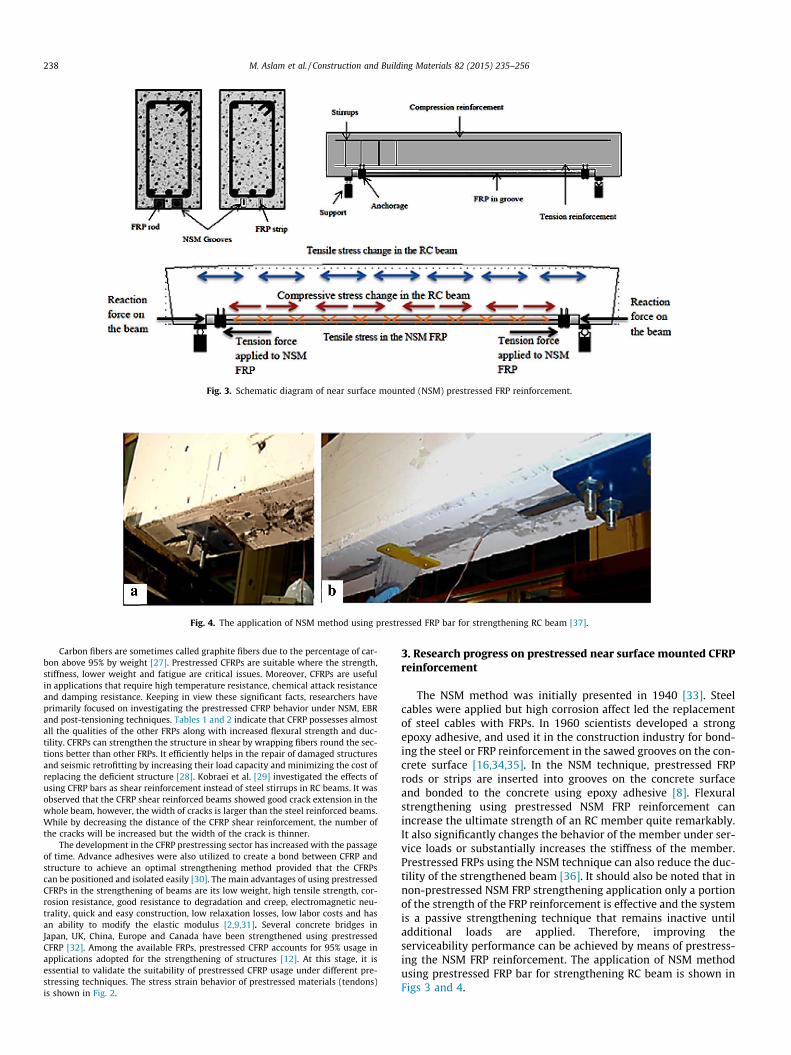
Fig. 3. Schematic diagram of near surface mounted (NSM) prestressed FRP reinforcement.
Fig. 4. The application of NSM method using prestressed FRP bar for strengthening RC beam [37].
238 M. Aslam et al. / Construction and Building Materials 82 (2015) 235–256
Carbon fibers are sometimes called graphite fibers due to the percentage of car-bon above 95% by weight [27]. Prestressed CFRPs are suitable where the strength,stiffness, lower weight and fatigue are critical issues. Moreover, CFRPs are usefulin applications that require high temperature resistance, chemical attack resistanceand damping resistance. Keeping in view these significant facts, researchers haveprimarily focused on investigating the prestressed CFRP behavior under NSM, EBRand post-tensioning techniques. Tables 1 and 2 indicate that CFRP possesses almostall the qualities of the other FRPs along with increased flexural strength and duc-tility. CFRPs can strengthen the structure in shear by wrapping fibers round the sec-tions better than other FRPs. It efficiently helps in the repair of damaged structuresand seismic retrofitting by increasing their load capacity and minimizing the cost ofreplacing the deficient structure [28]. Kobraei et al. [29] investigated the effects ofusing CFRP bars as shear reinforcement instead of steel stirrups in RC beams. It wasobserved that the CFRP shear reinforced beams showed good crack extension in thewhole beam, however, the width of cracks is larger than the steel reinforced beams.While by decreasing the distance of the CFRP shear reinforcement, the number ofthe cracks will be increased but the width of the crack is thinner.
The development in the CFRP prestressing sector has increased with the passageof time. Advance adhesives were also utilized to create a bond between CFRP andstructure to achieve an optimal strengthening method provided that the CFRPscan be positioned and isolated easily [30]. The main advantages of using prestressedCFRPs in the strengthening of beams are its low weight, high tensile strength, cor-rosion resistance, good resistance to degradation and creep, electromagnetic neu-trality, quick and easy construction, low relaxation losses, low labor costs and hasan ability to modify the elastic modulus [2,9,31]. Several concrete bridges inJapan, UK, China, Europe and Canada have been strengthened using prestressedCFRP [32]. Among the available FRPs, prestressed CFRP accounts for 95% usage inapplications adopted for the strengthening of structures [12]. At this stage, it isessential to validate the suitability of prestressed CFRP usage under different pre-stressing techniques. The stress strain behavior of prestressed materials (tendons)is shown in Fig. 2.
3. Research progress on prestressed near surface mounted CFRPreinforcement
The NSM method was initially presented in 1940 [33]. Steelcables were applied but high corrosion affect led the replacementof steel cables with FRPs. In 1960 scientists developed a strongepoxy adhesive, and used it in the construction industry for bond-ing the steel or FRP reinforcement in the sawed grooves on the con-crete surface [16,34,35]. In the NSM technique, prestressed FRProds or strips are inserted into grooves on the concrete surfaceand bonded to the concrete using epoxy adhesive [8]. Flexuralstrengthening using prestressed NSM FRP reinforcement canincrease the ultimate strength of an RC member quite remarkably.It also significantly changes the behavior of the member under ser-vice loads or substantially increases the stiffness of the member.Prestressed FRPs using the NSM technique can also reduce the duc-tility of the strengthened beam [36]. It should also be noted that innon-prestressed NSM FRP strengthening application only a portionof the strength of the FRP reinforcement is effective and the systemis a passive strengthening technique that remains inactive untiladditional loads are applied. Therefore, improving theserviceability performance can be achieved by means of prestress-ing the NSM FRP reinforcement. The application of NSM methodusing prestressed FRP bar for strengthening RC beam is shown inFigs 3 and 4.
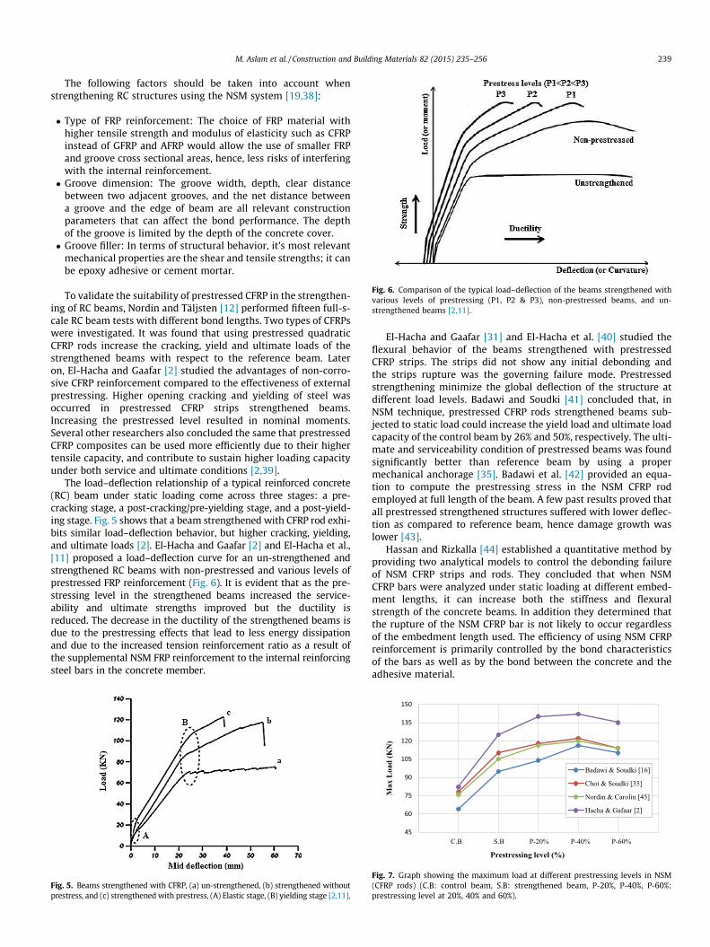
Fig. 6. Comparison of the typical load–deflection of the beams strengthened withvarious levels of prestressing (P1, P2 & P3), non-prestressed beams, and un-strengthened beams [2,11].
M. Aslam et al. / Construction and Building Materials 82 (2015) 235–256 239
The following factors should be taken into account whenstrengthening RC structures using the NSM system [19,38]:
� Type of FRP reinforcement: The choice of FRP material withhigher tensile strength and modulus of elasticity such as CFRPinstead of GFRP and AFRP would allow the use of smaller FRPand groove cross sectional areas, hence, less risks of interferingwith the internal reinforcement.� Groove dimension: The groove width, depth, clear distance
between two adjacent grooves, and the net distance betweena groove and the edge of beam are all relevant constructionparameters that can affect the bond performance. The depthof the groove is limited by the depth of the concrete cover.� Groove filler: In terms of structural behavior, it’s most relevant
mechanical properties are the shear and tensile strengths; it canbe epoxy adhesive or cement mortar.
To validate the suitability of prestressed CFRP in the strengthen-ing of RC beams, Nordin and Täljsten [12] performed fifteen full-s-cale RC beam tests with different bond lengths. Two types of CFRPswere investigated. It was found that using prestressed quadraticCFRP rods increase the cracking, yield and ultimate loads of thestrengthened beams with respect to the reference beam. Lateron, El-Hacha and Gaafar [2] studied the advantages of non-corro-sive CFRP reinforcement compared to the effectiveness of externalprestressing. Higher opening cracking and yielding of steel wasoccurred in prestressed CFRP strips strengthened beams.Increasing the prestressed level resulted in nominal moments.Several other researchers also concluded the same that prestressedCFRP composites can be used more efficiently due to their highertensile capacity, and contribute to sustain higher loading capacityunder both service and ultimate conditions [2,39].
The load–deflection relationship of a typical reinforced concrete(RC) beam under static loading come across three stages: a pre-cracking stage, a post-cracking/pre-yielding stage, and a post-yield-ing stage. Fig. 5 shows that a beam strengthened with CFRP rod exhi-bits similar load–deflection behavior, but higher cracking, yielding,and ultimate loads [2]. El-Hacha and Gaafar [2] and El-Hacha et al.,[11] proposed a load–deflection curve for an un-strengthened andstrengthened RC beams with non-prestressed and various levels ofprestressed FRP reinforcement (Fig. 6). It is evident that as the pre-stressing level in the strengthened beams increased the service-ability and ultimate strengths improved but the ductility isreduced. The decrease in the ductility of the strengthened beams isdue to the prestressing effects that lead to less energy dissipationand due to the increased tension reinforcement ratio as a result ofthe supplemental NSM FRP reinforcement to the internal reinforcingsteel bars in the concrete member.
Fig. 5. Beams strengthened with CFRP, (a) un-strengthened, (b) strengthened withoutprestress, and (c) strengthened with prestress, (A) Elastic stage, (B) yielding stage [2,11].
El-Hacha and Gaafar [31] and El-Hacha et al. [40] studied theflexural behavior of the beams strengthened with prestressedCFRP strips. The strips did not show any initial debonding andthe strips rupture was the governing failure mode. Prestressedstrengthening minimize the global deflection of the structure atdifferent load levels. Badawi and Soudki [41] concluded that, inNSM technique, prestressed CFRP rods strengthened beams sub-jected to static load could increase the yield load and ultimate loadcapacity of the control beam by 26% and 50%, respectively. The ulti-mate and serviceability condition of prestressed beams was foundsignificantly better than reference beam by using a propermechanical anchorage [35]. Badawi et al. [42] provided an equa-tion to compute the prestressing stress in the NSM CFRP rodemployed at full length of the beam. A few past results proved thatall prestressed strengthened structures suffered with lower deflec-tion as compared to reference beam, hence damage growth waslower [43].
Hassan and Rizkalla [44] established a quantitative method byproviding two analytical models to control the debonding failureof NSM CFRP strips and rods. They concluded that when NSMCFRP bars were analyzed under static loading at different embed-ment lengths, it can increase both the stiffness and flexuralstrength of the concrete beams. In addition they determined thatthe rupture of the NSM CFRP bar is not likely to occur regardlessof the embedment length used. The efficiency of using NSM CFRPreinforcement is primarily controlled by the bond characteristicsof the bars as well as by the bond between the concrete and theadhesive material.
45
60
75
90
105
120
135
150
Max
Loa
d (K
N)
Prestressing level (%)
Badawi & Soudki [16]
Choi & Soudki [35]
Nordin & Carolin [45]
Hacha & Gafaar [2]
C.B S.B P-20% P-40% P-60%
Fig. 7. Graph showing the maximum load at different prestressing levels in NSM(CFRP rods) (C.B: control beam, S.B: strengthened beam, P-20%, P-40%, P-60%:prestressing level at 20%, 40% and 60%).
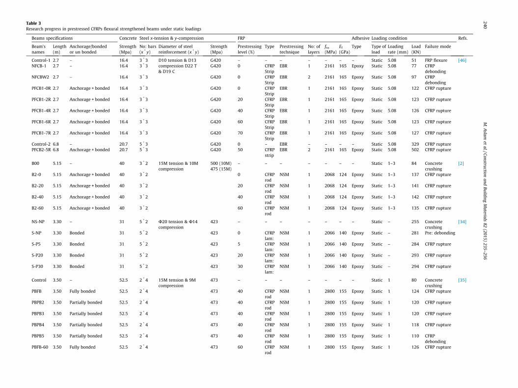
Table 3Research progress in prestressed CFRPs flexural strengthened beams under static loadings
Beams specifications Concrete Steel x-tension & y-compression FRP Adhesive Loading condition Refs.
Beam’snames
Length(m)
Anchorage/bondedor un bonded
Strength(Mpa)
No: bars(x * y)
Diameter of steelreinforcement (x * y)
Strength(Mpa)
Prestressinglevel (%)
Type Prestressingtechnique
No: oflayers
ftu
(MPa)Ef
(GPa)Type Type of
loadLoadingrate (mm)
Load(KN)
Failure mode
Control-1 2.7 – 16.4 3 * 3 D10 tension & D13compression D22 T& D19 C
G420 – – – – – – – Static 5.08 51 FRP flexure [46]NFCB-1 2.7 – 16.4 3 * 3 G420 0 CFRP
StripEBR 1 2161 165 Epoxy Static 5.08 77 CFRP
debondingNFCBW2 2.7 – 16.4 3 * 3 G420 0 CFRP
StripEBR 2 2161 165 Epoxy Static 5.08 97 CFRP
debondingPFCB1-0R 2.7 Anchorage + bonded 16.4 3 * 3 G420 0 CFRP
StripEBR 1 2161 165 Epoxy Static 5.08 122 CFRP rupture
PFCB1-2R 2.7 Anchorage + bonded 16.4 3 * 3 G420 20 CFRPStrip
EBR 1 2161 165 Epoxy Static 5.08 123 CFRP rupture
PFCB1-4R 2.7 Anchorage + bonded 16.4 3 * 3 G420 40 CFRPStrip
EBR 1 2161 165 Epoxy Static 5.08 126 CFRP rupture
PFCB1-6R 2.7 Anchorage + bonded 16.4 3 * 3 G420 60 CFRPStrip
EBR 1 2161 165 Epoxy Static 5.08 123 CFRP rupture
PFCB1-7R 2.7 Anchorage + bonded 16.4 3 * 3 G420 70 CFRPStrip
EBR 1 2161 165 Epoxy Static 5.08 127 CFRP rupture
Control-2 6.8 – 20.7 5 * 3 G420 0 – EBR – – – – Static 5.08 329 CFRP rupturePFCB2-5R 6.8 Anchorage + bonded 20.7 5 * 3 G420 50 CFRP
stripEBR 2 2161 165 Epoxy Static 5.08 502 CFRP rupture
B00 5.15 – 40 3 * 2 15M tension & 10Mcompression
500 (10M)475 (15M)
– – – – – – – Static 1–3 84 Concretecrushing
[2]
B2-0 5.15 Anchorage + bonded 40 3 * 2 0 CFRProd
NSM 1 2068 124 Epoxy Static 1–3 137 CFRP rupture
B2-20 5.15 Anchorage + bonded 40 3 * 2 20 CFRProd
NSM 1 2068 124 Epoxy Static 1–3 141 CFRP rupture
B2-40 5.15 Anchorage + bonded 40 3 * 2 40 CFRProd
NSM 1 2068 124 Epoxy Static 1–3 142 CFRP rupture
B2-60 5.15 Anchorage + bonded 40 3 * 2 60 CFRProd
NSM 1 2068 124 Epoxy Static 1–3 135 CFRP rupture
NS-NP 3.30 – 31 5 * 2 U20 tension & U14compression
423 – – – – – – – Static – 255 Concretecrushing
[34]
S-NP 3.30 Bonded 31 5 * 2 423 0 CFRPlam:
NSM 1 2066 140 Epoxy Static – 281 Pre: debonding
S-P5 3.30 Bonded 31 5 * 2 423 5 CFRPlam:
NSM 1 2066 140 Epoxy Static – 284 CFRP rupture
S-P20 3.30 Bonded 31 5 * 2 423 20 CFRPlam:
NSM 1 2066 140 Epoxy Static – 293 CFRP rupture
S-P30 3.30 Bonded 31 5 * 2 423 30 CFRPlam:
NSM 1 2066 140 Epoxy Static – 294 CFRP rupture
Control 3.50 – 52.5 2 * 4 15M tension & 9Mcompression
473 – – – – – – – Static 1 80 Concretecrushing
[35]
PBFB 3.50 Fully bonded 52.5 2 * 4 473 40 CFRProd
NSM 1 2800 155 Epoxy Static 1 124 CFRP rupture
PBPB2 3.50 Partially bonded 52.5 2 * 4 473 40 CFRProd
NSM 1 2800 155 Epoxy Static 1 120 CFRP rupture
PBPB3 3.50 Partially bonded 52.5 2 * 4 473 40 CFRProd
NSM 1 2800 155 Epoxy Static 1 120 CFRP rupture
PBPB4 3.50 Partially bonded 52.5 2 * 4 473 40 CFRProd
NSM 1 2800 155 Epoxy Static 1 118 CFRP rupture
PBPB5 3.50 Partially bonded 52.5 2 * 4 473 40 CFRProd
NSM 1 2800 155 Epoxy Static 1 110 CFRPdebonding
PBFB-60 3.50 Fully bonded 52.5 2 * 4 473 60 CFRProd
NSM 1 2800 155 Epoxy Static 1 126 CFRP rupture
240M
.Aslam
etal./Construction
andBuilding
Materials
82(2015)
235–256
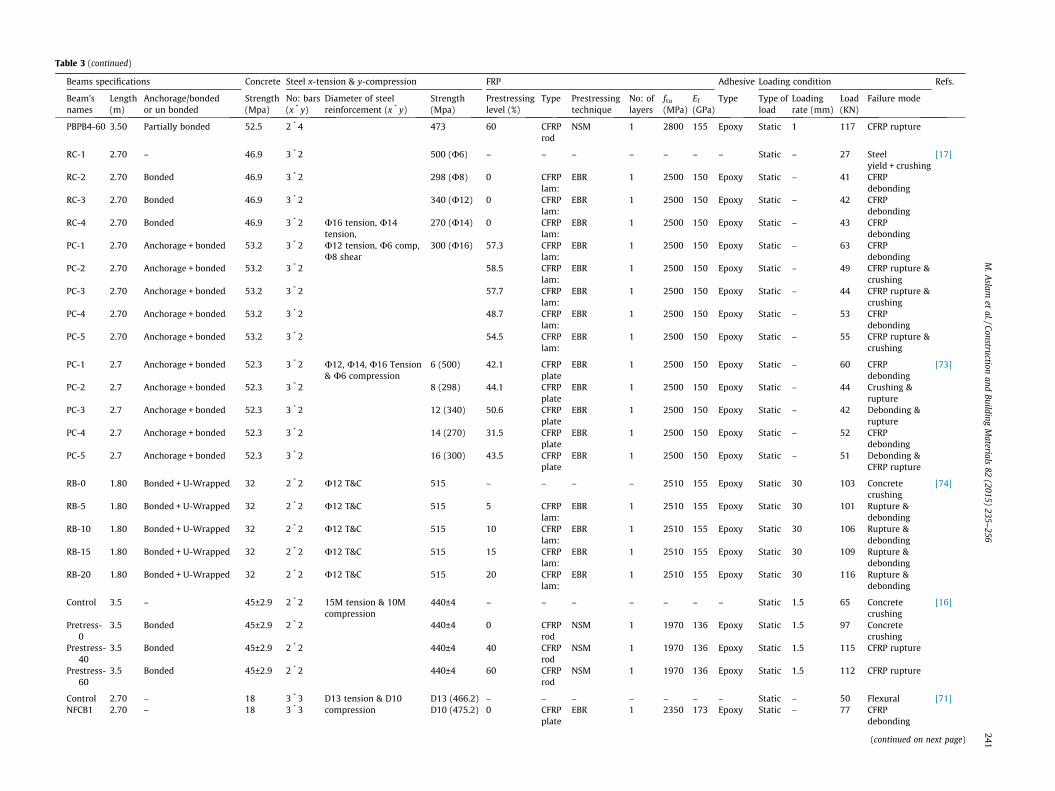
Table 3 (continued)
Beams specifications Concrete Steel x-tension & y-compression FRP Adhesive Loading condition Refs.
Beam’snames
Length(m)
Anchorage/bondedor un bonded
Strength(Mpa)
No: bars(x * y)
Diameter of steelreinforcement (x * y)
Strength(Mpa)
Prestressinglevel (%)
Type Prestressingtechnique
No: oflayers
ftu
(MPa)Ef
(GPa)Type Type of
loadLoadingrate (mm)
Load(KN)
Failure mode
PBPB4-60 3.50 Partially bonded 52.5 2 * 4 473 60 CFRProd
NSM 1 2800 155 Epoxy Static 1 117 CFRP rupture
RC-1 2.70 – 46.9 3 * 2 500 (U6) – – – – – – – Static – 27 Steelyield + crushing
[17]
RC-2 2.70 Bonded 46.9 3 * 2 298 (U8) 0 CFRPlam:
EBR 1 2500 150 Epoxy Static – 41 CFRPdebonding
RC-3 2.70 Bonded 46.9 3 * 2 340 (U12) 0 CFRPlam:
EBR 1 2500 150 Epoxy Static – 42 CFRPdebonding
RC-4 2.70 Bonded 46.9 3 * 2 U16 tension, U14tension,U12 tension, U6 comp,U8 shear
270 (U14) 0 CFRPlam:
EBR 1 2500 150 Epoxy Static – 43 CFRPdebonding
PC-1 2.70 Anchorage + bonded 53.2 3 * 2 300 (U16) 57.3 CFRPlam:
EBR 1 2500 150 Epoxy Static – 63 CFRPdebonding
PC-2 2.70 Anchorage + bonded 53.2 3 * 2 58.5 CFRPlam:
EBR 1 2500 150 Epoxy Static – 49 CFRP rupture &crushing
PC-3 2.70 Anchorage + bonded 53.2 3 * 2 57.7 CFRPlam:
EBR 1 2500 150 Epoxy Static – 44 CFRP rupture &crushing
PC-4 2.70 Anchorage + bonded 53.2 3 * 2 48.7 CFRPlam:
EBR 1 2500 150 Epoxy Static – 53 CFRPdebonding
PC-5 2.70 Anchorage + bonded 53.2 3 * 2 54.5 CFRPlam:
EBR 1 2500 150 Epoxy Static – 55 CFRP rupture &crushing
PC-1 2.7 Anchorage + bonded 52.3 3 * 2 U12, U14, U16 Tension& U6 compression
6 (500) 42.1 CFRPplate
EBR 1 2500 150 Epoxy Static – 60 CFRPdebonding
[73]
PC-2 2.7 Anchorage + bonded 52.3 3 * 2 8 (298) 44.1 CFRPplate
EBR 1 2500 150 Epoxy Static – 44 Crushing &rupture
PC-3 2.7 Anchorage + bonded 52.3 3 * 2 12 (340) 50.6 CFRPplate
EBR 1 2500 150 Epoxy Static – 42 Debonding &rupture
PC-4 2.7 Anchorage + bonded 52.3 3 * 2 14 (270) 31.5 CFRPplate
EBR 1 2500 150 Epoxy Static – 52 CFRPdebonding
PC-5 2.7 Anchorage + bonded 52.3 3 * 2 16 (300) 43.5 CFRPplate
EBR 1 2500 150 Epoxy Static – 51 Debonding &CFRP rupture
RB-0 1.80 Bonded + U-Wrapped 32 2 * 2 U12 T&C 515 – – – – 2510 155 Epoxy Static 30 103 Concretecrushing
[74]
RB-5 1.80 Bonded + U-Wrapped 32 2 * 2 U12 T&C 515 5 CFRPlam:
EBR 1 2510 155 Epoxy Static 30 101 Rupture &debonding
RB-10 1.80 Bonded + U-Wrapped 32 2 * 2 U12 T&C 515 10 CFRPlam:
EBR 1 2510 155 Epoxy Static 30 106 Rupture &debonding
RB-15 1.80 Bonded + U-Wrapped 32 2 * 2 U12 T&C 515 15 CFRPlam:
EBR 1 2510 155 Epoxy Static 30 109 Rupture &debonding
RB-20 1.80 Bonded + U-Wrapped 32 2 * 2 U12 T&C 515 20 CFRPlam:
EBR 1 2510 155 Epoxy Static 30 116 Rupture &debonding
Control 3.5 – 45±2.9 2 * 2 15M tension & 10Mcompression
440±4 – – – – – – – Static 1.5 65 Concretecrushing
[16]
Pretress-0
3.5 Bonded 45±2.9 2 * 2 440±4 0 CFRProd
NSM 1 1970 136 Epoxy Static 1.5 97 Concretecrushing
Prestress-40
3.5 Bonded 45±2.9 2 * 2 440±4 40 CFRProd
NSM 1 1970 136 Epoxy Static 1.5 115 CFRP rupture
Prestress-60
3.5 Bonded 45±2.9 2 * 2 440±4 60 CFRProd
NSM 1 1970 136 Epoxy Static 1.5 112 CFRP rupture
Control 2.70 – 18 3 * 3 D13 tension & D10compression
D13 (466.2) – – – – – – – Static – 50 Flexural [71]NFCB1 2.70 – 18 3 * 3 D10 (475.2) 0 CFRP
plateEBR 1 2350 173 Epoxy Static – 77 CFRP
debonding
(continued on next page)
M.A
slamet
al./Constructionand
BuildingM
aterials82
(2015)235–
256241

Table 3 (continued)
Beams specifications Concrete Steel x-tension & y-compression FRP Adhesive Loading condition Refs.
Beam’snames
Length(m)
Anchorage/bondedor un bonded
Strength(Mpa)
No: bars(x * y)
Diameter of steelreinforcement (x * y)
Strength(Mpa)
Prestressinglevel (%)
Type Prestressingtechnique
No: oflayers
ftu
(MPa)Ef
(GPa)Type Type of
loadLoadingrate (mm)
Load(KN)
Failure mode
NFCBW2 2.70 – 18 3 * 3 0 CFRPplate
EBR 2 2350 173 Epoxy Static – 99 CFRPDelamination
PFCU1-0R
2.70 Anchorage + unbounded 18 3 * 3 0 CFRPplate
EBR 1 2350 173 Epoxy Static – 115 CFRP rupture
PFCU1-2R
2.70 Anchorage + unbounded 18 3 * 3 20 CFRPPlate
EBR 1 2350 173 Epoxy Static – 120 CFRP rupture
PFCU1-4R
2.70 Anchorage + unbounded 18 3 * 3 40 CFRPplate
EBR 1 2350 173 Epoxy Static – 121 CFRP rupture
PFCU1-6R
2.70 Anchorage + unbounded 18 3 * 3 60 CFRPplate
EBR 1 2350 173 Epoxy Static – 123 CFRP rupture
PFCB1-0R 2.70 Anchorage + bonded 18 3 * 3 0 CFRPplate
EBR 1 2350 173 Epoxy Static – 122 Debonding &rupture
PFCB1-2R 2.70 Anchorage + bonded 18 3 * 3 20 CFRPplate
EBR 1 2350 173 Epoxy Static – 123 Debonding &rupture
PFCB1-4R 2.7 Anchorage + bonded 18 3 * 3 40 CFRPplate
EBR 1 2350 173 Epoxy Static – 126 Debonding &rupture
PFCB1-6R 2.7 Anchorage + bonded 18 3 * 3 60 CFRPplate
EBR 1 2350 173 Epoxy Static – 123 Debonding &rupture
PFCU1-4L 4.80 Anchorage + unbounded 18 3 * 3 60 CFRPplate
EBR 1 2350 173 Epoxy Static – 122 CFRP rupture
PFCU1-6L 6.30 Anchorage + unbounded 18 3 * 3 60 CFRPplate
EBR 1 2350 173 Epoxy Static – 72 CFRP rupture
B00 5.15 – 46 3 * 2 15M tension & 10Mcompression
475 – – – – – – – Static – 84 Concretecrushing
[31]
B1 5.15 Anchorage + bonded 46 3 * 2 475 0 CFRPstrips
NSM 2 2610 145 Epoxy Static – 135 CFRP rupture
B1 5.15 Anchorage + bonded 43 3 * 2 475 20 CFRPstrips
NSM 2 2610 145 Epoxy Static – 148 CFRP rupture
B1 5.15 Anchorage + bonded 40 3 * 2 475 40 CFRPstrips
NSM 2 2610 145 Epoxy Static – 149 CFRP rupture
B1 5.15 Anchorage + bonded 40 3 * 2 475 60 CFRPstrips
NSM 2 2610 145 Epoxy Static – 149 CFRP rupture
MU-III 3.3 – 26.4 3 * 2 D13, D16, D19 tension &D10 compression
– – – – – – – Static 60 75 Flexural [72]M0-III 3.3 Anchorage + bonded 26.4 3 * 2 D10 (500.7) 0 CFRP
plateEBR 1 2850 165 Epoxy Static 60 90 CFRP
debondingM4-III 3.3 Anchorage + bonded 26.4 3 * 2 D13 (498.7) 40 CFRP
plateEBR 1 2850 165 Epoxy Static 60 121 Tension
M6-III 3.3 Anchorage + bonded 26.4 3 * 2 D16 (476.2) 60 CFRPplate
EBR 1 2850 165 Epoxy Static 60 119 Tension
M8-III 3.3 Anchorage + bonded 26.4 3 * 2 And 80 CFRPplate
EBR 1 2850 165 Epoxy Static 60 126 Tension
M4-1 3.3 Anchorage + bonded 26.4 3 * 2 D19 (465.8) 40 CFRPplate
EBR 1 2850 165 Epoxy Static 60 82 Tension
M6-1 3.3 Anchorage + bonded 26.4 3 * 2 60 CFRPplate
EBR 1 2850 165 Epoxy Static 60 88 Tension
M8-1 3.3 Anchorage + bonded 26.4 3 * 2 80 CFRPplate
EBR 1 2850 165 Epoxy Static 60 91 –
M6-2 3.3 Anchorage + bonded 26.4 3 * 2 60 CFRPplate
EBR 1 2850 165 Epoxy Static 60 110 –
M8-2 3.3 Anchorage + bonded 26.4 3 * 2 80 CFRPplate
EBR 1 2850 165 Epoxy Static 60 117 Tension
M6-IV 3.3 Anchorage + bonded 26.4 3 * 2 60 CFRPplate
EBR 1 2850 165 Epoxy Static 60 146 Tension
242M
.Aslam
etal./Construction
andBuilding
Materials
82(2015)
235–256
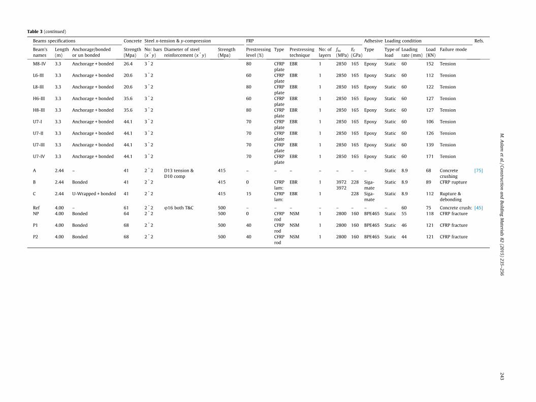
Table 3 (continued)
Beams specifications Concrete Steel x-tension & y-compression FRP Adhes Loading condition Refs.
Beam’snames
Length(m)
Anchorage/bondedor un bonded
Strength(Mpa)
No: bars(x * y)
Diameter of steelreinforcement (x * y)
Strength(Mpa)
Prestressinglevel (%)
Type Prestressingtechnique
No: oflayers
ftu
(MPa)Ef
(GPa)Type Type of
loadLoadingrate (mm)
Load(KN)
Failure mode
M8-IV 3.3 Anchorage + bonded 26.4 3 * 2 80 CFRPplate
EBR 1 2850 165 Epoxy Static 60 152 Tension
L6-III 3.3 Anchorage + bonded 20.6 3 * 2 60 CFRPplate
EBR 1 2850 165 Epoxy Static 60 112 Tension
L8-III 3.3 Anchorage + bonded 20.6 3 * 2 80 CFRPplate
EBR 1 2850 165 Epoxy Static 60 122 Tension
H6-III 3.3 Anchorage + bonded 35.6 3 * 2 60 CFRPplate
EBR 1 2850 165 Epoxy Static 60 127 Tension
H8-III 3.3 Anchorage + bonded 35.6 3 * 2 80 CFRPplate
EBR 1 2850 165 Epoxy Static 60 127 Tension
U7-I 3.3 Anchorage + bonded 44.1 3 * 2 70 CFRPplate
EBR 1 2850 165 Epoxy Static 60 106 Tension
U7-II 3.3 Anchorage + bonded 44.1 3 * 2 70 CFRPplate
EBR 1 2850 165 Epoxy Static 60 126 Tension
U7-III 3.3 Anchorage + bonded 44.1 3 * 2 70 CFRPplate
EBR 1 2850 165 Epoxy Static 60 139 Tension
U7-IV 3.3 Anchorage + bonded 44.1 3 * 2 70 CFRPplate
EBR 1 2850 165 Epoxy Static 60 171 Tension
A 2.44 – 41 2 * 2 D13 tension &D10 comp
415 – – – – – – – Static 8.9 68 Concretecrushing
[75]
B 2.44 Bonded 41 2 * 2 415 0 CFRPlam:
EBR 1 39723972
228 Siga-mate
Static 8.9 89 CFRP rupture
C 2.44 U-Wrapped + bonded 41 2 * 2 415 15 CFRPlam:
EBR 1 228 Siga-mate
Static 8.9 112 Rupture &debonding
Ref 4.00 – 61 2 * 2 u16 both T&C 500 – – – – – – – – 60 75 Concrete crush: [45]NP 4.00 Bonded 64 2 * 2 500 0 CFRP
rodNSM 1 2800 160 BPE46 Static 55 118 CFRP fracture
P1 4.00 Bonded 68 2 * 2 500 40 CFRProd
NSM 1 2800 160 BPE46 Static 46 121 CFRP fracture
P2 4.00 Bonded 68 2 * 2 500 40 CFRProd
NSM 1 2800 160 BPE46 Static 44 121 CFRP fracture
M.A
slamet
al./Constructionand
BuildingM
aterials82
(2015)235–
256243
ive
5
5
5
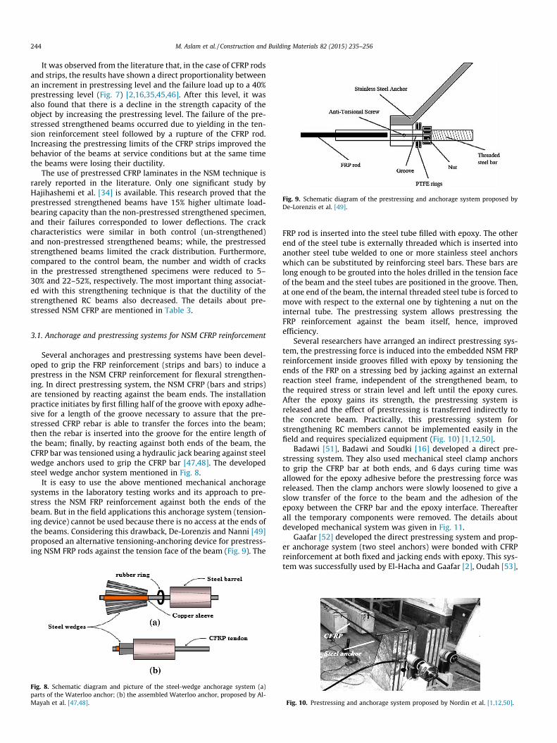
Fig. 9. Schematic diagram of the prestressing and anchorage system proposed byDe-Lorenzis et al. [49].
244 M. Aslam et al. / Construction and Building Materials 82 (2015) 235–256
It was observed from the literature that, in the case of CFRP rodsand strips, the results have shown a direct proportionality betweenan increment in prestressing level and the failure load up to a 40%prestressing level (Fig. 7) [2,16,35,45,46]. After this level, it wasalso found that there is a decline in the strength capacity of theobject by increasing the prestressing level. The failure of the pre-stressed strengthened beams occurred due to yielding in the ten-sion reinforcement steel followed by a rupture of the CFRP rod.Increasing the prestressing limits of the CFRP strips improved thebehavior of the beams at service conditions but at the same timethe beams were losing their ductility.
The use of prestressed CFRP laminates in the NSM technique israrely reported in the literature. Only one significant study byHajihashemi et al. [34] is available. This research proved that theprestressed strengthened beams have 15% higher ultimate load-bearing capacity than the non-prestressed strengthened specimen,and their failures corresponded to lower deflections. The crackcharacteristics were similar in both control (un-strengthened)and non-prestressed strengthened beams; while, the prestressedstrengthened beams limited the crack distribution. Furthermore,compared to the control beam, the number and width of cracksin the prestressed strengthened specimens were reduced to 5–30% and 22–52%, respectively. The most important thing associat-ed with this strengthening technique is that the ductility of thestrengthened RC beams also decreased. The details about pre-stressed NSM CFRP are mentioned in Table 3.
3.1. Anchorage and prestressing systems for NSM CFRP reinforcement
Several anchorages and prestressing systems have been devel-oped to grip the FRP reinforcement (strips and bars) to induce aprestress in the NSM CFRP reinforcement for flexural strengthen-ing. In direct prestressing system, the NSM CFRP (bars and strips)are tensioned by reacting against the beam ends. The installationpractice initiates by first filling half of the groove with epoxy adhe-sive for a length of the groove necessary to assure that the pre-stressed CFRP rebar is able to transfer the forces into the beam;then the rebar is inserted into the groove for the entire length ofthe beam; finally, by reacting against both ends of the beam, theCFRP bar was tensioned using a hydraulic jack bearing against steelwedge anchors used to grip the CFRP bar [47,48]. The developedsteel wedge anchor system mentioned in Fig. 8.
It is easy to use the above mentioned mechanical anchoragesystems in the laboratory testing works and its approach to pre-stress the NSM FRP reinforcement against both the ends of thebeam. But in the field applications this anchorage system (tension-ing device) cannot be used because there is no access at the ends ofthe beams. Considering this drawback, De-Lorenzis and Nanni [49]proposed an alternative tensioning-anchoring device for prestress-ing NSM FRP rods against the tension face of the beam (Fig. 9). The
Fig. 8. Schematic diagram and picture of the steel-wedge anchorage system (a)parts of the Waterloo anchor; (b) the assembled Waterloo anchor, proposed by Al-Mayah et al. [47,48].
FRP rod is inserted into the steel tube filled with epoxy. The otherend of the steel tube is externally threaded which is inserted intoanother steel tube welded to one or more stainless steel anchorswhich can be substituted by reinforcing steel bars. These bars arelong enough to be grouted into the holes drilled in the tension faceof the beam and the steel tubes are positioned in the groove. Then,at one end of the beam, the internal threaded steel tube is forced tomove with respect to the external one by tightening a nut on theinternal tube. The prestressing system allows prestressing theFRP reinforcement against the beam itself, hence, improvedefficiency.
Several researchers have arranged an indirect prestressing sys-tem, the prestressing force is induced into the embedded NSM FRPreinforcement inside grooves filled with epoxy by tensioning theends of the FRP on a stressing bed by jacking against an externalreaction steel frame, independent of the strengthened beam, tothe required stress or strain level and left until the epoxy cures.After the epoxy gains its strength, the prestressing system isreleased and the effect of prestressing is transferred indirectly tothe concrete beam. Practically, this prestressing system forstrengthening RC members cannot be implemented easily in thefield and requires specialized equipment (Fig. 10) [1,12,50].
Badawi [51], Badawi and Soudki [16] developed a direct pre-stressing system. They also used mechanical steel clamp anchorsto grip the CFRP bar at both ends, and 6 days curing time wasallowed for the epoxy adhesive before the prestressing force wasreleased. Then the clamp anchors were slowly loosened to give aslow transfer of the force to the beam and the adhesion of theepoxy between the CFRP bar and the epoxy interface. Thereafterall the temporary components were removed. The details aboutdeveloped mechanical system was given in Fig. 11.
Gaafar [52] developed the direct prestressing system and prop-er anchorage system (two steel anchors) were bonded with CFRPreinforcement at both fixed and jacking ends with epoxy. This sys-tem was successfully used by El-Hacha and Gaafar [2], Oudah [53],
Fig. 10. Prestressing and anchorage system proposed by Nordin et al. [1,12,50].
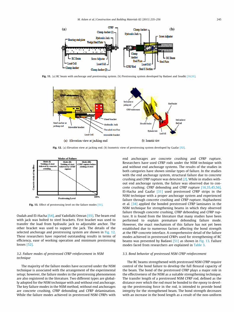
Fig. 11. (a) RC beam with anchorage and prestressing system. (b) Prestressing system developed by Badawi and Soudki [16,51].
Fig. 12. (a) Elevation view at jacking end. (b) Isometric view of prestressing system developed by Gaafar [52].
Fig. 13. Effect of prestressing level on the failure modes [51].
M. Aslam et al. / Construction and Building Materials 82 (2015) 235–256 245
Oudah and El-Hacha [54], and Yadollahi Omran [55]. The beam endwith jack was bolted to steel brackets. First bracket was used totransfer the load from hydraulic jack to adjustable anchor. Theother bracket was used to support the jack. The details of theselected anchorage and prestressing system are shown in Fig. 12.These researchers have reported outstanding results in terms ofefficiency, ease of working operation and minimum prestressinglosses [52].
3.2. Failure modes of prestressed CFRP reinforcement in NSMtechnique
The majority of the failure modes have occurred under the NSMtechnique is associated with the arrangement of the experimentalsetup; however, the failure modes in the prestressing phenomenonare also registered in the literature. Two different types are global-ly adopted for the NSM technique with and without end anchorage.The key failure modes in the NSM method, without end anchoragesare concrete crushing, CFRP debonding and CFRP delamination.While the failure modes achieved in prestressed NSM CFRPs with
end anchorages are concrete crushing and CFRP rupture.Researchers have used CFRP rods under the NSM technique withand without end anchorage systems. The results of the studies inboth categories have shown similar types of failure. In the studieswith the end anchorage system, structural failure due to concretecrushing and CFRP rupture was detected [2]. While in studies with-out end anchorage system, the failure was observed due to con-crete crushing; CFRP debonding and CFRP rupture [16,35,45,56].El-Hacha and Gaafar [31] used prestressed CFRP strips in theNSM technique with a proper anchorage system and experiencedfailure through concrete crushing and CFRP rupture. Hajihashemiet al. [34] applied the bonded prestressed CFRP laminates in theNSM technique for strengthening beams in which they observedfailure through concrete crushing, CFRP debonding and CFRP rup-ture. It is found from the literature that many studies have beenperformed to explain premature debonding failure mode.However, the exact mechanism of this failure has not yet beenestablished due to numerous factors affecting the bond strengthat the FRP-concrete interface. A comprehensive detail of the failuremodes achieved in prestressed CFRPs used for strengthening of RCbeams was presented by Badawi [51] as shown in Fig. 13. Failuremodes faced from researchers are explained in Table 3.
3.3. Bond behavior of prestressed NSM CFRP reinforcement
The RC beams strengthened with prestressed NSM CFRP requirecontrol of the bond failure to develop the full flexural capacity ofthe beam. The bond of the prestressed CFRP plays a major role inthe effectiveness of the NSM as a suitable strengthening technique.The transfer length of a prestressed NSM CFRP rod, defined as thedistance over which the rod must be bonded to the epoxy to devel-op the prestressing force in the rod, is intended to provide bondintegrity for the strengthened beam. The bond strength decreaseswith an increase in the bond length as a result of the non-uniform
246 M. Aslam et al. / Construction and Building Materials 82 (2015) 235–256
distribution of bond stresses. The transfer length of CFRP rodsembedded in epoxy is expected to be different from the behaviorof CFRP rods in concrete [36]. Badawi et al. [42] suggested anempirical equation based on curve fitting of the measured datato estimate the transfer length of prestressed NSM CFRP bar:
f s ¼ f preð1� exp�BxÞ ð1Þ
where fs (prestressing stress) in the CFRP bar at a given distance (x)from the end of the bonded length, fpre (maximum prestressingstress), B is a factor to account the rod type, type and the thicknessof the epoxy, and the method of force releasing [42].
The test variables were the type of CFRP rod and the level ofprestressing force in the rods (40%, 45%, 50%, and 60% of the tensilecapacity of the CFRP rod). The average transfer length of the NSMCFRP spirally wound rod was found to range from 190 mm to350 mm for the 40–60% prestressing levels, and 160 mm at 40%prestressing level for sand blasted rods [36].
Wahab et al. [57] conducted bond tests on RC strengthenedbeams with non-prestressed and prestressed NSM CFRP rods understatic loading to understand the mechanism of bond failure. Thetest variable were the presence of tension steel, type of CFRP rod(sand blasted and spirally wound), and the level of prestressingforce (0%, 40%, 45%). They found that the transfer length of the pre-stressed CFRP rod was found to be 150 mm and 210 mm for theprestressed sand blasted and spirally wound rods, respectively.The failure mode for non-prestressed NSM CFRP strengthenedbeams was pull-out between the CFRP rod and the epoxy. The fail-ure mode for the prestressed NSM CFRP strengthened beamsdepended on the type of rod used. For the sand blasted rods, thefailure was the same as the non-prestressed strengthened beams.For the spirally wound rods, failure was by pull-out of the rod fromthe epoxy in the region close to the support.
3.4. Effect of prestress level on ductility and deformability in NSM CFRPstrengthened RC beams
The serviceability condition in terms of reduced crack widthand deflection, and the ultimate load carrying capacity of pre-stressed NSM CFRP may improve with an increase in the level ofthe prestressing force, while ductility (defined as the ratio ofdeflection at ultimate load to deflection at yield load) and deforma-bility (defined as the ratio of the deflection at failure to the deflec-tion at steel yielding) of the strengthened beams may decreasewith an increase in the prestressing force, and the RC beams mayfail due to rupture of the CFRP [2,16,58]. The reduction in the duc-tility is due to the increase of the tension reinforcement (steel andCFRP) and prestressing, which leads to less energy dissipation.
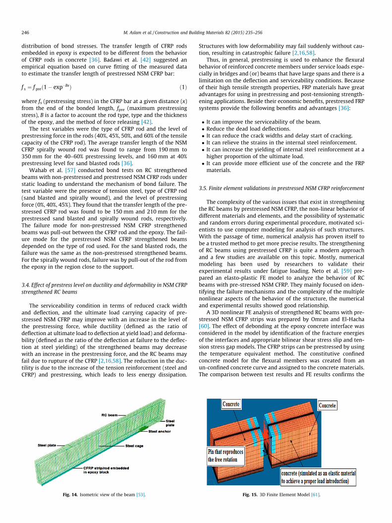
Fig. 14. Isometric view of the beam [53].
Structures with low deformability may fail suddenly without cau-tion, resulting in catastrophic failure [2,16,58].
Thus, in general, prestressing is used to enhance the flexuralbehavior of reinforced concrete members under service loads espe-cially in bridges and (or) beams that have large spans and there is alimitation on the deflection and serviceability conditions. Becauseof their high tensile strength properties, FRP materials have greatadvantages for using in prestressing and post-tensioning strength-ening applications. Beside their economic benefits, prestressed FRPsystems provide the following benefits and advantages [36]:
� It can improve the serviceability of the beam.� Reduce the dead load deflections.� It can reduce the crack widths and delay start of cracking.� It can relieve the strains in the internal steel reinforcement.� It can increase the yielding of internal steel reinforcement at a
higher proportion of the ultimate load.� It can provide more efficient use of the concrete and the FRP
materials.
3.5. Finite element validations in prestressed NSM CFRP reinforcement
The complexity of the various issues that exist in strengtheningthe RC beams by prestressed NSM CFRP, the non-linear behavior ofdifferent materials and elements, and the possibility of systematicand random errors during experimental procedure, motivated sci-entists to use computer modeling for analysis of such structures.With the passage of time, numerical analysis has proven itself tobe a trusted method to get more precise results. The strengtheningof RC beams using prestressed CFRP is quite a modern approachand a few studies are available on this topic. Mostly, numericalmodeling has been used by researchers to validate theirexperimental results under fatigue loading. Neto et al. [59] pre-pared an elasto-plastic FE model to analyze the behavior of RCbeams with pre-stressed NSM CFRP. They mainly focused on iden-tifying the failure mechanisms and the complexity of the multiplenonlinear aspects of the behavior of the structure, the numericaland experimental results showed good relationship.
A 3D nonlinear FE analysis of strengthened RC beams with pre-stressed NSM CFRP strips was prepared by Omran and El-Hacha[60]. The effect of debonding at the epoxy concrete interface wasconsidered in the model by identification of the fracture energiesof the interfaces and appropriate bilinear shear stress slip and ten-sion stress gap models. The CFRP strips can be prestressed by usingthe temperature equivalent method. The constitutive confinedconcrete model for the flexural members was created from anun-confined concrete curve and assigned to the concrete materials.The comparison between test results and FE results confirms the
Fig. 15. 3D Finite Element Model [61].
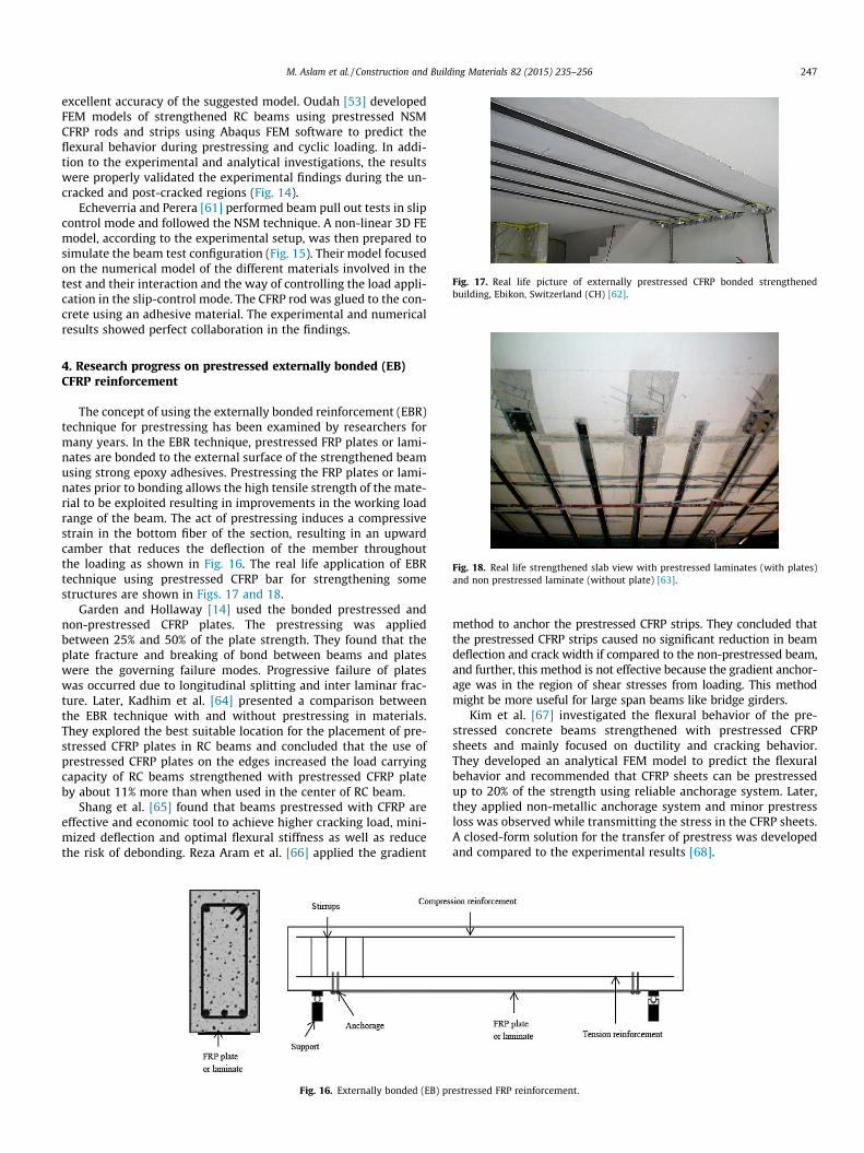
Fig. 17. Real life picture of externally prestressed CFRP bonded strengthenedbuilding, Ebikon, Switzerland (CH) [62].
M. Aslam et al. / Construction and Building Materials 82 (2015) 235–256 247
excellent accuracy of the suggested model. Oudah [53] developedFEM models of strengthened RC beams using prestressed NSMCFRP rods and strips using Abaqus FEM software to predict theflexural behavior during prestressing and cyclic loading. In addi-tion to the experimental and analytical investigations, the resultswere properly validated the experimental findings during the un-cracked and post-cracked regions (Fig. 14).
Echeverria and Perera [61] performed beam pull out tests in slipcontrol mode and followed the NSM technique. A non-linear 3D FEmodel, according to the experimental setup, was then prepared tosimulate the beam test configuration (Fig. 15). Their model focusedon the numerical model of the different materials involved in thetest and their interaction and the way of controlling the load appli-cation in the slip-control mode. The CFRP rod was glued to the con-crete using an adhesive material. The experimental and numericalresults showed perfect collaboration in the findings.
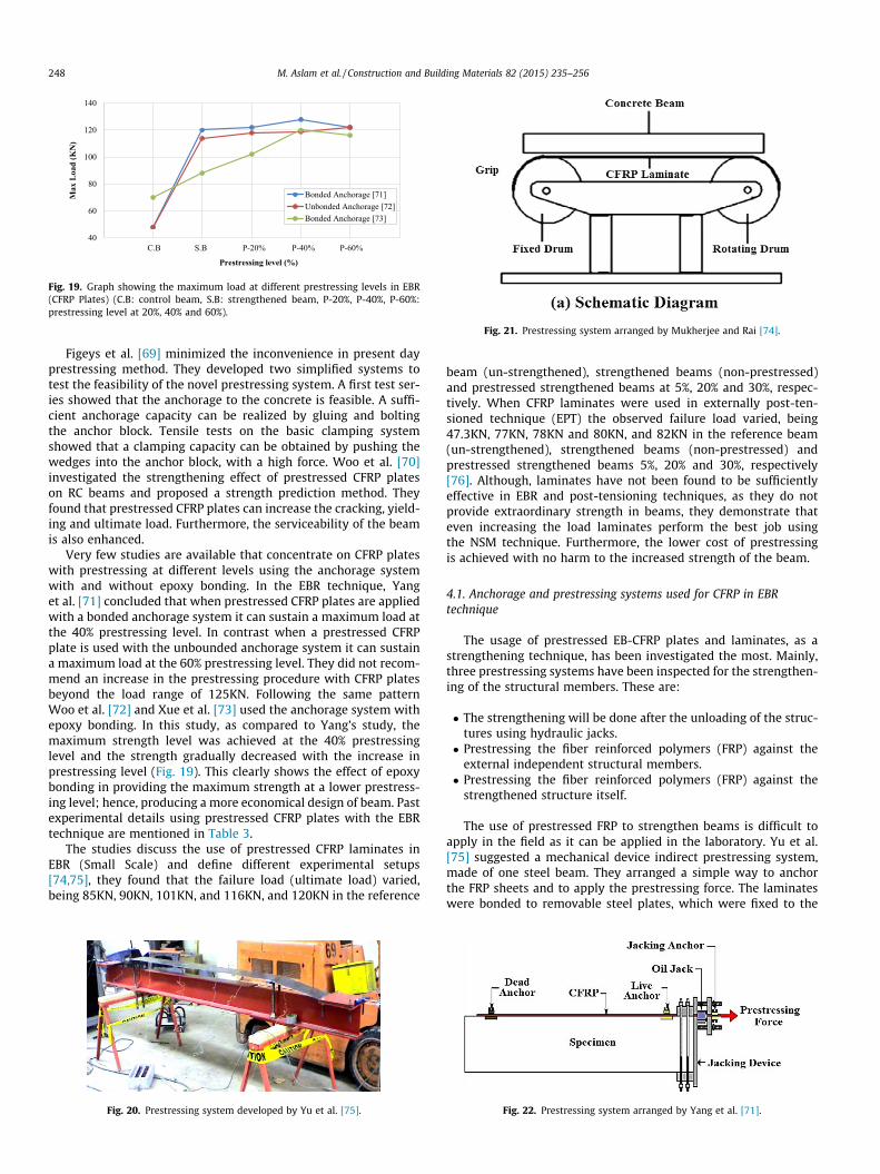
Fig. 18. Real life strengthened slab view with prestressed laminates (with plates)and non prestressed laminate (without plate) [63].
4. Research progress on prestressed externally bonded (EB)CFRP reinforcement
The concept of using the externally bonded reinforcement (EBR)technique for prestressing has been examined by researchers formany years. In the EBR technique, prestressed FRP plates or lami-nates are bonded to the external surface of the strengthened beamusing strong epoxy adhesives. Prestressing the FRP plates or lami-nates prior to bonding allows the high tensile strength of the mate-rial to be exploited resulting in improvements in the working loadrange of the beam. The act of prestressing induces a compressivestrain in the bottom fiber of the section, resulting in an upwardcamber that reduces the deflection of the member throughoutthe loading as shown in Fig. 16. The real life application of EBRtechnique using prestressed CFRP bar for strengthening somestructures are shown in Figs. 17 and 18.
Garden and Hollaway [14] used the bonded prestressed andnon-prestressed CFRP plates. The prestressing was appliedbetween 25% and 50% of the plate strength. They found that theplate fracture and breaking of bond between beams and plateswere the governing failure modes. Progressive failure of plateswas occurred due to longitudinal splitting and inter laminar frac-ture. Later, Kadhim et al. [64] presented a comparison betweenthe EBR technique with and without prestressing in materials.They explored the best suitable location for the placement of pre-stressed CFRP plates in RC beams and concluded that the use ofprestressed CFRP plates on the edges increased the load carryingcapacity of RC beams strengthened with prestressed CFRP plateby about 11% more than when used in the center of RC beam.
Shang et al. [65] found that beams prestressed with CFRP areeffective and economic tool to achieve higher cracking load, mini-mized deflection and optimal flexural stiffness as well as reducethe risk of debonding. Reza Aram et al. [66] applied the gradient
Fig. 16. Externally bonded (EB) pr
method to anchor the prestressed CFRP strips. They concluded thatthe prestressed CFRP strips caused no significant reduction in beamdeflection and crack width if compared to the non-prestressed beam,and further, this method is not effective because the gradient anchor-age was in the region of shear stresses from loading. This methodmight be more useful for large span beams like bridge girders.
Kim et al. [67] investigated the flexural behavior of the pre-stressed concrete beams strengthened with prestressed CFRPsheets and mainly focused on ductility and cracking behavior.They developed an analytical FEM model to predict the flexuralbehavior and recommended that CFRP sheets can be prestressedup to 20% of the strength using reliable anchorage system. Later,they applied non-metallic anchorage system and minor prestressloss was observed while transmitting the stress in the CFRP sheets.A closed-form solution for the transfer of prestress was developedand compared to the experimental results [68].
estressed FRP reinforcement.
40
60
80
100
120
140
Max
Loa
d (K
N)
Prestressing level (%)
Bonded Anchorage [71]Unbonded Anchorage [72]Bonded Anchorage [73]
C.B S.B P-20% P-40% P-60%
Fig. 19. Graph showing the maximum load at different prestressing levels in EBR(CFRP Plates) (C.B: control beam, S.B: strengthened beam, P-20%, P-40%, P-60%:prestressing level at 20%, 40% and 60%).
Fig. 21. Prestressing system arranged by Mukherjee and Rai [74].
248 M. Aslam et al. / Construction and Building Materials 82 (2015) 235–256
Figeys et al. [69] minimized the inconvenience in present dayprestressing method. They developed two simplified systems totest the feasibility of the novel prestressing system. A first test ser-ies showed that the anchorage to the concrete is feasible. A suffi-cient anchorage capacity can be realized by gluing and boltingthe anchor block. Tensile tests on the basic clamping systemshowed that a clamping capacity can be obtained by pushing thewedges into the anchor block, with a high force. Woo et al. [70]investigated the strengthening effect of prestressed CFRP plateson RC beams and proposed a strength prediction method. Theyfound that prestressed CFRP plates can increase the cracking, yield-ing and ultimate load. Furthermore, the serviceability of the beamis also enhanced.
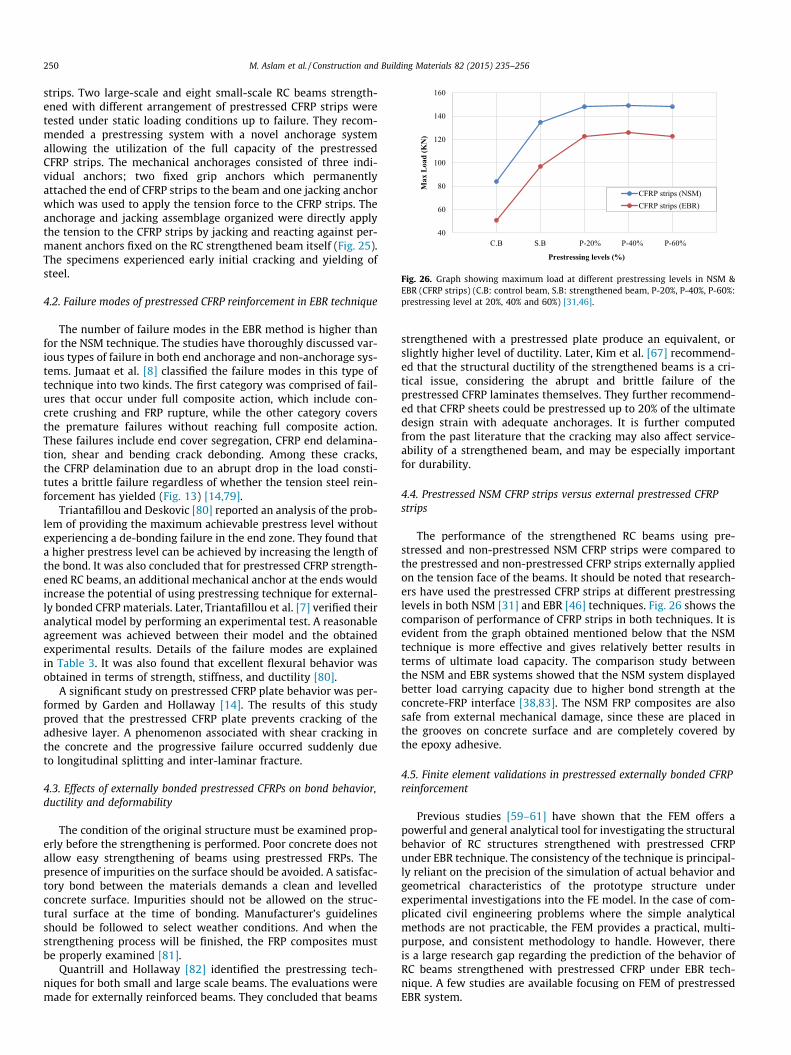
Very few studies are available that concentrate on CFRP plateswith prestressing at different levels using the anchorage systemwith and without epoxy bonding. In the EBR technique, Yanget al. [71] concluded that when prestressed CFRP plates are appliedwith a bonded anchorage system it can sustain a maximum load atthe 40% prestressing level. In contrast when a prestressed CFRPplate is used with the unbounded anchorage system it can sustaina maximum load at the 60% prestressing level. They did not recom-mend an increase in the prestressing procedure with CFRP platesbeyond the load range of 125KN. Following the same patternWoo et al. [72] and Xue et al. [73] used the anchorage system withepoxy bonding. In this study, as compared to Yang’s study, themaximum strength level was achieved at the 40% prestressinglevel and the strength gradually decreased with the increase inprestressing level (Fig. 19). This clearly shows the effect of epoxybonding in providing the maximum strength at a lower prestress-ing level; hence, producing a more economical design of beam. Pastexperimental details using prestressed CFRP plates with the EBRtechnique are mentioned in Table 3.
The studies discuss the use of prestressed CFRP laminates inEBR (Small Scale) and define different experimental setups[74,75], they found that the failure load (ultimate load) varied,being 85KN, 90KN, 101KN, and 116KN, and 120KN in the reference
Fig. 20. Prestressing system developed by Yu et al. [75].
beam (un-strengthened), strengthened beams (non-prestressed)and prestressed strengthened beams at 5%, 20% and 30%, respec-tively. When CFRP laminates were used in externally post-ten-sioned technique (EPT) the observed failure load varied, being47.3KN, 77KN, 78KN and 80KN, and 82KN in the reference beam(un-strengthened), strengthened beams (non-prestressed) andprestressed strengthened beams 5%, 20% and 30%, respectively[76]. Although, laminates have not been found to be sufficientlyeffective in EBR and post-tensioning techniques, as they do notprovide extraordinary strength in beams, they demonstrate thateven increasing the load laminates perform the best job usingthe NSM technique. Furthermore, the lower cost of prestressingis achieved with no harm to the increased strength of the beam.
4.1. Anchorage and prestressing systems used for CFRP in EBRtechnique
The usage of prestressed EB-CFRP plates and laminates, as astrengthening technique, has been investigated the most. Mainly,three prestressing systems have been inspected for the strengthen-ing of the structural members. These are:
� The strengthening will be done after the unloading of the struc-tures using hydraulic jacks.� Prestressing the fiber reinforced polymers (FRP) against the
external independent structural members.� Prestressing the fiber reinforced polymers (FRP) against the
strengthened structure itself.
The use of prestressed FRP to strengthen beams is difficult toapply in the field as it can be applied in the laboratory. Yu et al.[75] suggested a mechanical device indirect prestressing system,made of one steel beam. They arranged a simple way to anchorthe FRP sheets and to apply the prestressing force. The laminateswere bonded to removable steel plates, which were fixed to the
Fig. 22. Prestressing system arranged by Yang et al. [71].
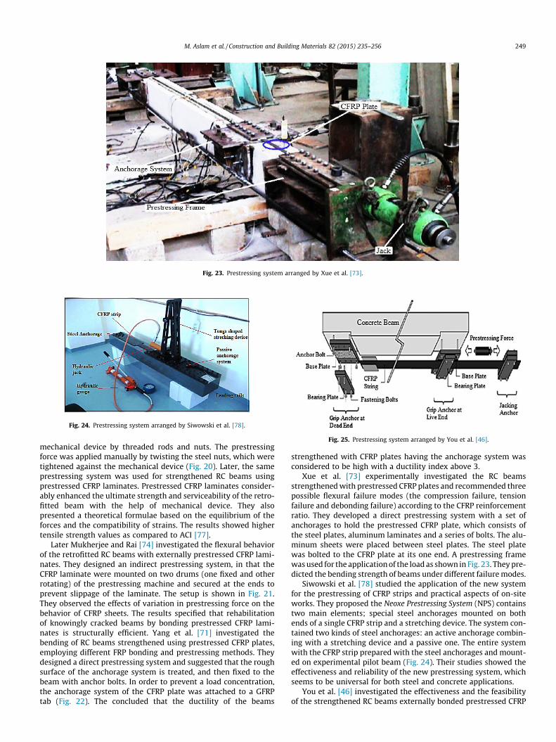
Fig. 23. Prestressing system arranged by Xue et al. [73].
Fig. 24. Prestressing system arranged by Siwowski et al. [78].
Fig. 25. Prestressing system arranged by You et al. [46].
M. Aslam et al. / Construction and Building Materials 82 (2015) 235–256 249
mechanical device by threaded rods and nuts. The prestressingforce was applied manually by twisting the steel nuts, which weretightened against the mechanical device (Fig. 20). Later, the sameprestressing system was used for strengthened RC beams usingprestressed CFRP laminates. Prestressed CFRP laminates consider-ably enhanced the ultimate strength and serviceability of the retro-fitted beam with the help of mechanical device. They alsopresented a theoretical formulae based on the equilibrium of theforces and the compatibility of strains. The results showed highertensile strength values as compared to ACI [77].
Later Mukherjee and Rai [74] investigated the flexural behaviorof the retrofitted RC beams with externally prestressed CFRP lami-nates. They designed an indirect prestressing system, in that theCFRP laminate were mounted on two drums (one fixed and otherrotating) of the prestressing machine and secured at the ends toprevent slippage of the laminate. The setup is shown in Fig. 21.They observed the effects of variation in prestressing force on thebehavior of CFRP sheets. The results specified that rehabilitationof knowingly cracked beams by bonding prestressed CFRP lami-nates is structurally efficient. Yang et al. [71] investigated thebending of RC beams strengthened using prestressed CFRP plates,employing different FRP bonding and prestressing methods. Theydesigned a direct prestressing system and suggested that the roughsurface of the anchorage system is treated, and then fixed to thebeam with anchor bolts. In order to prevent a load concentration,the anchorage system of the CFRP plate was attached to a GFRPtab (Fig. 22). The concluded that the ductility of the beams
strengthened with CFRP plates having the anchorage system wasconsidered to be high with a ductility index above 3.
Xue et al. [73] experimentally investigated the RC beamsstrengthened with prestressed CFRP plates and recommended threepossible flexural failure modes (the compression failure, tensionfailure and debonding failure) according to the CFRP reinforcementratio. They developed a direct prestressing system with a set ofanchorages to hold the prestressed CFRP plate, which consists ofthe steel plates, aluminum laminates and a series of bolts. The alu-minum sheets were placed between steel plates. The steel platewas bolted to the CFRP plate at its one end. A prestressing framewas used for the application of the load as shown in Fig. 23. They pre-dicted the bending strength of beams under different failure modes.
Siwowski et al. [78] studied the application of the new systemfor the prestressing of CFRP strips and practical aspects of on-siteworks. They proposed the Neoxe Prestressing System (NPS) containstwo main elements; special steel anchorages mounted on bothends of a single CFRP strip and a stretching device. The system con-tained two kinds of steel anchorages: an active anchorage combin-ing with a stretching device and a passive one. The entire systemwith the CFRP strip prepared with the steel anchorages and mount-ed on experimental pilot beam (Fig. 24). Their studies showed theeffectiveness and reliability of the new prestressing system, whichseems to be universal for both steel and concrete applications.
You et al. [46] investigated the effectiveness and the feasibilityof the strengthened RC beams externally bonded prestressed CFRP
40
60
80
100
120
140
160
Max
Loa
d (K
N)
Prestressing levels (%)
CFRP strips (NSM)CFRP strips (EBR)
C.B S.B P-20% P-40% P-60%
Fig. 26. Graph showing maximum load at different prestressing levels in NSM &EBR (CFRP strips) (C.B: control beam, S.B: strengthened beam, P-20%, P-40%, P-60%:prestressing level at 20%, 40% and 60%) [31,46].
250 M. Aslam et al. / Construction and Building Materials 82 (2015) 235–256
strips. Two large-scale and eight small-scale RC beams strength-ened with different arrangement of prestressed CFRP strips weretested under static loading conditions up to failure. They recom-mended a prestressing system with a novel anchorage systemallowing the utilization of the full capacity of the prestressedCFRP strips. The mechanical anchorages consisted of three indi-vidual anchors; two fixed grip anchors which permanentlyattached the end of CFRP strips to the beam and one jacking anchorwhich was used to apply the tension force to the CFRP strips. Theanchorage and jacking assemblage organized were directly applythe tension to the CFRP strips by jacking and reacting against per-manent anchors fixed on the RC strengthened beam itself (Fig. 25).The specimens experienced early initial cracking and yielding ofsteel.
4.2. Failure modes of prestressed CFRP reinforcement in EBR technique
The number of failure modes in the EBR method is higher thanfor the NSM technique. The studies have thoroughly discussed var-ious types of failure in both end anchorage and non-anchorage sys-tems. Jumaat et al. [8] classified the failure modes in this type oftechnique into two kinds. The first category was comprised of fail-ures that occur under full composite action, which include con-crete crushing and FRP rupture, while the other category coversthe premature failures without reaching full composite action.These failures include end cover segregation, CFRP end delamina-tion, shear and bending crack debonding. Among these cracks,the CFRP delamination due to an abrupt drop in the load consti-tutes a brittle failure regardless of whether the tension steel rein-forcement has yielded (Fig. 13) [14,79].
Triantafillou and Deskovic [80] reported an analysis of the prob-lem of providing the maximum achievable prestress level withoutexperiencing a de-bonding failure in the end zone. They found thata higher prestress level can be achieved by increasing the length ofthe bond. It was also concluded that for prestressed CFRP strength-ened RC beams, an additional mechanical anchor at the ends wouldincrease the potential of using prestressing technique for external-ly bonded CFRP materials. Later, Triantafillou et al. [7] verified theiranalytical model by performing an experimental test. A reasonableagreement was achieved between their model and the obtainedexperimental results. Details of the failure modes are explainedin Table 3. It was also found that excellent flexural behavior wasobtained in terms of strength, stiffness, and ductility [80].
A significant study on prestressed CFRP plate behavior was per-formed by Garden and Hollaway [14]. The results of this studyproved that the prestressed CFRP plate prevents cracking of theadhesive layer. A phenomenon associated with shear cracking inthe concrete and the progressive failure occurred suddenly dueto longitudinal splitting and inter-laminar fracture.
4.3. Effects of externally bonded prestressed CFRPs on bond behavior,ductility and deformability
The condition of the original structure must be examined prop-erly before the strengthening is performed. Poor concrete does notallow easy strengthening of beams using prestressed FRPs. Thepresence of impurities on the surface should be avoided. A satisfac-tory bond between the materials demands a clean and levelledconcrete surface. Impurities should not be allowed on the struc-tural surface at the time of bonding. Manufacturer’s guidelinesshould be followed to select weather conditions. And when thestrengthening process will be finished, the FRP composites mustbe properly examined [81].
Quantrill and Hollaway [82] identified the prestressing tech-niques for both small and large scale beams. The evaluations weremade for externally reinforced beams. They concluded that beams
strengthened with a prestressed plate produce an equivalent, orslightly higher level of ductility. Later, Kim et al. [67] recommend-ed that the structural ductility of the strengthened beams is a cri-tical issue, considering the abrupt and brittle failure of theprestressed CFRP laminates themselves. They further recommend-ed that CFRP sheets could be prestressed up to 20% of the ultimatedesign strain with adequate anchorages. It is further computedfrom the past literature that the cracking may also affect service-ability of a strengthened beam, and may be especially importantfor durability.
4.4. Prestressed NSM CFRP strips versus external prestressed CFRPstrips
The performance of the strengthened RC beams using pre-stressed and non-prestressed NSM CFRP strips were compared tothe prestressed and non-prestressed CFRP strips externally appliedon the tension face of the beams. It should be noted that research-ers have used the prestressed CFRP strips at different prestressinglevels in both NSM [31] and EBR [46] techniques. Fig. 26 shows thecomparison of performance of CFRP strips in both techniques. It isevident from the graph obtained mentioned below that the NSMtechnique is more effective and gives relatively better results interms of ultimate load capacity. The comparison study betweenthe NSM and EBR systems showed that the NSM system displayedbetter load carrying capacity due to higher bond strength at theconcrete-FRP interface [38,83]. The NSM FRP composites are alsosafe from external mechanical damage, since these are placed inthe grooves on concrete surface and are completely covered bythe epoxy adhesive.
4.5. Finite element validations in prestressed externally bonded CFRPreinforcement
Previous studies [59–61] have shown that the FEM offers apowerful and general analytical tool for investigating the structuralbehavior of RC structures strengthened with prestressed CFRPunder EBR technique. The consistency of the technique is principal-ly reliant on the precision of the simulation of actual behavior andgeometrical characteristics of the prototype structure underexperimental investigations into the FE model. In the case of com-plicated civil engineering problems where the simple analyticalmethods are not practicable, the FEM provides a practical, multi-purpose, and consistent methodology to handle. However, thereis a large research gap regarding the prediction of the behavior ofRC beams strengthened with prestressed CFRP under EBR tech-nique. A few studies are available focusing on FEM of prestressedEBR system.
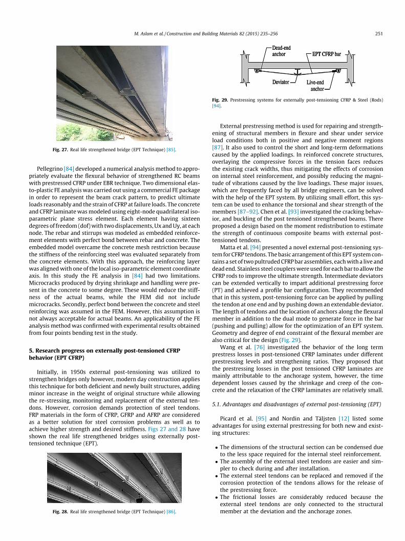
Fig. 27. Real life strengthened bridge (EPT Technique) [85].
Fig. 29. Prestressing systems for externally post-tensioning CFRP & Steel (Rods)[94].
M. Aslam et al. / Construction and Building Materials 82 (2015) 235–256 251
Pellegrino [84] developed a numerical analysis method to appro-priately evaluate the flexural behavior of strengthened RC beamswith prestressed CFRP under EBR technique. Two dimensional elas-to-plastic FE analysis was carried out using a commercial FE packagein order to represent the beam crack pattern, to predict ultimateloads reasonably and the strain of CFRP at failure loads. The concreteand CFRP laminate was modeled using eight-node quadrilateral iso-parametric plane stress element. Each element having sixteendegrees of freedom (dof) with two displacements, Ux and Uy, at eachnode. The rebar and stirrups was modeled as embedded reinforce-ment elements with perfect bond between rebar and concrete. Theembedded model overcame the concrete mesh restriction becausethe stiffness of the reinforcing steel was evaluated separately fromthe concrete elements. With this approach, the reinforcing layerwas aligned with one of the local iso-parametric element coordinateaxis. In this study the FE analysis in [84] had two limitations.Microcracks produced by drying shrinkage and handling were pre-sent in the concrete to some degree. These would reduce the stiff-ness of the actual beams, while the FEM did not includemicrocracks. Secondly, perfect bond between the concrete and steelreinforcing was assumed in the FEM. However, this assumption isnot always acceptable for actual beams. An applicability of the FEanalysis method was confirmed with experimental results obtainedfrom four points bending test in the study.
5. Research progress on externally post-tensioned CFRPbehavior (EPT CFRP)
Initially, in 1950s external post-tensioning was utilized tostrengthen bridges only however, modern day construction appliesthis technique for both deficient and newly built structures, addingminor increase in the weight of original structure while allowingthe re-stressing, monitoring and replacement of the external ten-dons. However, corrosion demands protection of steel tendons.FRP materials in the form of CFRP, GFRP and AFRP are consideredas a better solution for steel corrosion problems as well as toachieve higher strength and desired stiffness. Figs 27 and 28 haveshown the real life strengthened bridges using externally post-tensioned technique (EPT).
Fig. 28. Real life strengthened bridge (EPT Technique) [86].
External prestressing method is used for repairing and strength-ening of structural members in flexure and shear under serviceload conditions both in positive and negative moment regions[87]. It also used to control the short and long-term deformationscaused by the applied loadings. In reinforced concrete structures,overlaying the compressive forces in the tension faces reducesthe existing crack widths, thus mitigating the effects of corrosionon internal steel reinforcement, and possibly reducing the magni-tude of vibrations caused by the live loadings. These major issues,which are frequently faced by all bridge engineers, can be solvedwith the help of the EPT system. By utilizing small effort, this sys-tem can be used to enhance the torsional and shear strength of themembers [87–92]. Chen et al. [93] investigated the cracking behav-ior, and buckling of the post tensioned strengthened beams. Thereproposed a design based on the moment redistribution to estimatethe strength of continuous composite beams with external post-tensioned tendons.
Matta et al. [94] presented a novel external post-tensioning sys-tem for CFRP tendons. The basic arrangement of this EPT system con-tains a set of two pultruded CFRP bar assemblies, each with a live anddead end. Stainless steel couplers were used for each bar to allow theCFRP rods to improve the ultimate strength. Intermediate deviatorscan be extended vertically to impart additional prestressing force(PT) and achieved a profile bar configuration. They recommendedthat in this system, post-tensioning force can be applied by pullingthe tendon at one end and by pushing down an extendable deviator.The length of tendons and the location of anchors along the flexuralmember in addition to the dual mode to generate force in the bar(pushing and pulling) allow for the optimization of an EPT system.Geometry and degree of end constraint of the flexural member arealso critical for the design (Fig. 29).
Wang et al. [76] investigated the behavior of the long termprestress losses in post-tensioned CFRP laminates under differentprestressing levels and strengthening ratios. They proposed thatthe prestressing losses in the post tensioned CFRP laminates aremainly attributable to the anchorage system, however, the timedependent losses caused by the shrinkage and creep of the con-crete and the relaxation of the CFRP laminates are relatively small.
5.1. Advantages and disadvantages of external post-tensioning (EPT)
Picard et al. [95] and Nordin and Täljsten [12] listed someadvantages for using external prestressing for both new and exist-ing structures:
� The dimensions of the structural section can be condensed dueto the less space required for the internal steel reinforcement.� The assembly of the external steel tendons are easier and sim-
pler to check during and after installation.� The external steel tendons can be replaced and removed if the
corrosion protection of the tendons allows for the release ofthe prestressing force.� The frictional losses are considerably reduced because the
external steel tendons are only connected to the structuralmember at the deviation and the anchorage zones.
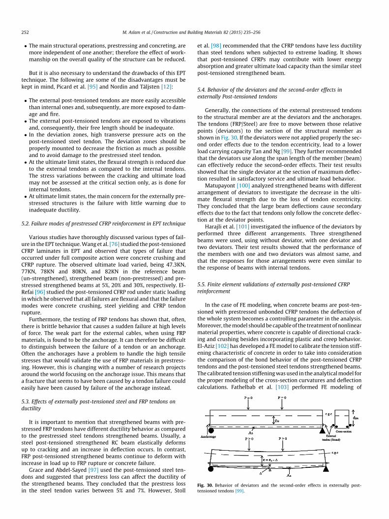
Fig. 30. Behavior of deviators and the second-order effects in externally post-tensioned tendons [99].
252 M. Aslam et al. / Construction and Building Materials 82 (2015) 235–256
� The main structural operations, prestressing and concreting, aremore independent of one another; therefore the effect of work-manship on the overall quality of the structure can be reduced.
But it is also necessary to understand the drawbacks of this EPTtechnique. The following are some of the disadvantages must bekept in mind, Picard et al. [95] and Nordin and Täljsten [12]:
� The external post-tensioned tendons are more easily accessiblethan internal ones and, subsequently, are more exposed to dam-age and fire.� The external post-tensioned tendons are exposed to vibrations
and, consequently, their free length should be inadequate.� In the deviation zones, high transverse pressure acts on the
post-tensioned steel tendon. The deviation zones should beproperly mounted to decrease the friction as much as possibleand to avoid damage to the prestressed steel tendon.� At the ultimate limit states, the flexural strength is reduced due
to the external tendons as compared to the internal tendons.The stress variations between the cracking and ultimate loadmay not be assessed at the critical section only, as is done forinternal tendons.� At ultimate limit states, the main concern for the externally pre-
stressed structures is the failure with little warning due toinadequate ductility.
5.2. Failure modes of prestressed CFRP reinforcement in EPT technique
Various studies have thoroughly discussed various types of fail-ure in the EPT technique. Wang et al. [76] studied the post-tensionedCFRP laminates in EPT and observed that types of failure thatoccurred under full composite action were concrete crushing andCFRP rupture. The observed ultimate load varied, being 47.3KN,77KN, 78KN and 80KN, and 82KN in the reference beam(un-strengthened), strengthened beam (non-prestressed) and pre-stressed strengthened beams at 5%, 20% and 30%, respectively. El-Refai [96] studied the post-tensioned CFRP rod under static loadingin which he observed that all failures are flexural and that the failuremodes were concrete crushing, steel yielding and CFRP tendonrupture.
Furthermore, the testing of FRP tendons has shown that, often,there is brittle behavior that causes a sudden failure at high levelsof force. The weak part for the external cables, when using FRPmaterials, is found to be the anchorage. It can therefore be difficultto distinguish between the failure of a tendon or an anchorage.Often the anchorages have a problem to handle the high tensilestresses that would validate the use of FRP materials in prestress-ing. However, this is changing with a number of research projectsaround the world focusing on the anchorage issue. This means thata fracture that seems to have been caused by a tendon failure couldeasily have been caused by failure of the anchorage instead.
5.3. Effects of externally post-tensioned steel and FRP tendons onductility
It is important to mention that strengthened beams with pre-stressed FRP tendons have different ductility behavior as comparedto the prestressed steel tendons strengthened beams. Usually, asteel post-tensioned strengthened RC beam elastically deformsup to cracking and an increase in deflection occurs. In contrast,FRP post-tensioned strengthened beams continue to deform withincrease in load up to FRP rupture or concrete failure.
Grace and Abdel-Sayed [97] used the post-tensioned steel ten-dons and suggested that prestress loss can affect the ductility ofthe strengthened beams. They concluded that the prestress lossin the steel tendon varies between 5% and 7%. However, Stoll
et al. [98] recommended that the CFRP tendons have less ductilitythan steel tendons when subjected to extreme loading. It showsthat post-tensioned CFRPs may contribute with lower energyabsorption and greater ultimate load capacity than the similar steelpost-tensioned strengthened beam.
5.4. Behavior of the deviators and the second-order effects inexternally Post-tensioned tendons
Generally, the connections of the external prestressed tendonsto the structural member are at the deviators and the anchorages.The tendons (FRP/Steel) are free to move between those relativepoints (deviators) to the section of the structural member asshown in Fig. 30. If the deviators were not applied properly the sec-ond order effects due to the tendon eccentricity, lead to a lowerload carrying capacity Tan and Ng [99]. They further recommendedthat the deviators use along the span length of the member (beam)can effectively reduce the second-order effects. Their test resultsshowed that the single deviator at the section of maximum deflec-tion resulted in satisfactory service and ultimate load behavior.
Matupayont [100] analyzed strengthened beams with differentarrangement of deviators to investigate the decrease in the ulti-mate flexural strength due to the loss of tendon eccentricity.They concluded that the large beam deflections cause secondaryeffects due to the fact that tendons only follow the concrete deflec-tion at the deviator points.
Harajli et al. [101] investigated the influence of the deviators byperformed three different arrangements. Three strengthenedbeams were used, using without deviator, with one deviator andtwo deviators. Their test results showed that the performance ofthe members with one and two deviators was almost same, andthat the responses for those arrangements were even similar tothe response of beams with internal tendons.
5.5. Finite element validations of externally post-tensioned CFRPreinforcement
In the case of FE modeling, when concrete beams are post-ten-sioned with prestressed unbonded CFRP tendons the deflection ofthe whole system becomes a controlling parameter in the analysis.Moreover, the model should be capable of the treatment of nonlinearmaterial properties, where concrete is capable of directional crack-ing and crushing besides incorporating plastic and creep behavior.El-Aziz [102] has developed a FE model to calibrate the tension stiff-ening characteristic of concrete in order to take into considerationthe comparison of the bond behavior of the post-tensioned CFRPtendons and the post-tensioned steel tendons strengthened beams.The calibrated tension stiffening was used in the analytical model forthe proper modeling of the cross-section curvatures and deflectioncalculations. Fathelbab et al. [103] performed FE modeling of
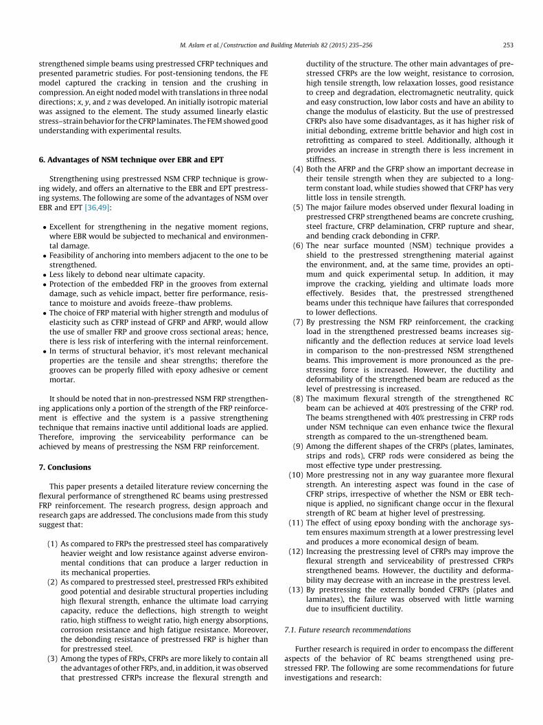
M. Aslam et al. / Construction and Building Materials 82 (2015) 235–256 253
strengthened simple beams using prestressed CFRP techniques andpresented parametric studies. For post-tensioning tendons, the FEmodel captured the cracking in tension and the crushing incompression. An eight noded model with translations in three nodaldirections; x, y, and z was developed. An initially isotropic materialwas assigned to the element. The study assumed linearly elasticstress–strain behavior for the CFRP laminates. The FEM showed goodunderstanding with experimental results.
6. Advantages of NSM technique over EBR and EPT
Strengthening using prestressed NSM CFRP technique is grow-ing widely, and offers an alternative to the EBR and EPT prestress-ing systems. The following are some of the advantages of NSM overEBR and EPT [36,49]:
� Excellent for strengthening in the negative moment regions,where EBR would be subjected to mechanical and environmen-tal damage.� Feasibility of anchoring into members adjacent to the one to be
strengthened.� Less likely to debond near ultimate capacity.� Protection of the embedded FRP in the grooves from external
damage, such as vehicle impact, better fire performance, resis-tance to moisture and avoids freeze–thaw problems.� The choice of FRP material with higher strength and modulus of
elasticity such as CFRP instead of GFRP and AFRP, would allowthe use of smaller FRP and groove cross sectional areas; hence,there is less risk of interfering with the internal reinforcement.� In terms of structural behavior, it’s most relevant mechanical
properties are the tensile and shear strengths; therefore thegrooves can be properly filled with epoxy adhesive or cementmortar.
It should be noted that in non-prestressed NSM FRP strengthen-ing applications only a portion of the strength of the FRP reinforce-ment is effective and the system is a passive strengtheningtechnique that remains inactive until additional loads are applied.Therefore, improving the serviceability performance can beachieved by means of prestressing the NSM FRP reinforcement.
7. Conclusions
This paper presents a detailed literature review concerning theflexural performance of strengthened RC beams using prestressedFRP reinforcement. The research progress, design approach andresearch gaps are addressed. The conclusions made from this studysuggest that:
(1) As compared to FRPs the prestressed steel has comparativelyheavier weight and low resistance against adverse environ-mental conditions that can produce a larger reduction inits mechanical properties.
(2) As compared to prestressed steel, prestressed FRPs exhibitedgood potential and desirable structural properties includinghigh flexural strength, enhance the ultimate load carryingcapacity, reduce the deflections, high strength to weightratio, high stiffness to weight ratio, high energy absorptions,corrosion resistance and high fatigue resistance. Moreover,the debonding resistance of prestressed FRP is higher thanfor prestressed steel.
(3) Among the types of FRPs, CFRPs are more likely to contain allthe advantages of other FRPs, and, in addition, it was observedthat prestressed CFRPs increase the flexural strength and
ductility of the structure. The other main advantages of pre-stressed CFRPs are the low weight, resistance to corrosion,high tensile strength, low relaxation losses, good resistanceto creep and degradation, electromagnetic neutrality, quickand easy construction, low labor costs and have an ability tochange the modulus of elasticity. But the use of prestressedCFRPs also have some disadvantages, as it has higher risk ofinitial debonding, extreme brittle behavior and high cost inretrofitting as compared to steel. Additionally, although itprovides an increase in strength there is less increment instiffness.
(4) Both the AFRP and the GFRP show an important decrease intheir tensile strength when they are subjected to a long-term constant load, while studies showed that CFRP has verylittle loss in tensile strength.
(5) The major failure modes observed under flexural loading inprestressed CFRP strengthened beams are concrete crushing,steel fracture, CFRP delamination, CFRP rupture and shear,and bending crack debonding in CFRP.
(6) The near surface mounted (NSM) technique provides ashield to the prestressed strengthening material againstthe environment, and, at the same time, provides an opti-mum and quick experimental setup. In addition, it mayimprove the cracking, yielding and ultimate loads moreeffectively. Besides that, the prestressed strengthenedbeams under this technique have failures that correspondedto lower deflections.
(7) By prestressing the NSM FRP reinforcement, the crackingload in the strengthened prestressed beams increases sig-nificantly and the deflection reduces at service load levelsin comparison to the non-prestressed NSM strengthenedbeams. This improvement is more pronounced as the pre-stressing force is increased. However, the ductility anddeformability of the strengthened beam are reduced as thelevel of prestressing is increased.
(8) The maximum flexural strength of the strengthened RCbeam can be achieved at 40% prestressing of the CFRP rod.The beams strengthened with 40% prestressing in CFRP rodsunder NSM technique can even enhance twice the flexuralstrength as compared to the un-strengthened beam.
(9) Among the different shapes of the CFRPs (plates, laminates,strips and rods), CFRP rods were considered as being themost effective type under prestressing.
(10) More prestressing not in any way guarantee more flexuralstrength. An interesting aspect was found in the case ofCFRP strips, irrespective of whether the NSM or EBR tech-nique is applied, no significant change occur in the flexuralstrength of RC beam at higher level of prestressing.
(11) The effect of using epoxy bonding with the anchorage sys-tem ensures maximum strength at a lower prestressing leveland produces a more economical design of beam.
(12) Increasing the prestressing level of CFRPs may improve theflexural strength and serviceability of prestressed CFRPsstrengthened beams. However, the ductility and deforma-bility may decrease with an increase in the prestress level.
(13) By prestressing the externally bonded CFRPs (plates andlaminates), the failure was observed with little warningdue to insufficient ductility.
7.1. Future research recommendations
Further research is required in order to encompass the differentaspects of the behavior of RC beams strengthened using pre-stressed FRP. The following are some recommendations for futureinvestigations and research:

254 M. Aslam et al. / Construction and Building Materials 82 (2015) 235–256
(1) Since the end of most beams or girders in buildings andbridges is not accessible, the prestressed strengthening sys-tem needs the development of a prestressing assembly suit-able for real-life conditions. Anchor bolts may be a feasiblesolution to tightly attach the prestressing assembly to thebottom of structures and the bar alignment might be slightlybent for the prestressing function. The behavior of deviatorsmay play an important role in this situation and hence,should be considered during design procedure.
(2) The effects of pre-damaging in the beams due to early crack-ing, simulated delamination and persistent load needs fur-ther study.
(3) CFRP covers a very high percentage of usage of prestressedFRP applications being adopted for strengthening RC beams.More research is required to investigate the behavior of RCbeams strengthened using other types of FRPs such asAFRP, GFRP and other hybrid systems.
(4) Critical issues relating to prestressed FRP anchorages and theuse of proper test methods to verify their performance haveto be addressed more consistently in the future. For FRP pre-stressing applications, anchorage systems have to be devel-oped to meet the same requirements as those for steelprestressing systems and thus compete at the same level.Fire protection of anchorages also needs evaluation.
(5) The long term durability behavior of bond in FRP prestress-ing tendons is not yet defined. Furthermore, research isneeded to investigate the galvanic action and external FRPpost-tensioning for rehabilitation.
(6) The FRP strengthening system adopted in the majority of thestudies was EB sheets, and to a limited extent, EB-strips.However, very few researchers investigated the performanceof NSM and Powder Actuated Fastener applied (PAF) sys-tems. Therefore, the NSM and PAF techniques need furtherstudy.
(7) Very limited researchers have investigated the performanceand properties of strengthened beams under effect of envi-ronmental exposure such as; temperature, humidity, corro-sion, freeze–thaw, and dry-wet cycles.
(8) The adverse environmental conditions and variable fatigueload due to continuously running traffic fluctuate the servicebehavior of on bridge girders. An accurate estimation of thebehavior of in-service RC girders strengthened with pre-stressed NSM CFRP reinforcement needs concentration ofresearchers.
(9) High prestressing levels may initiate potential slippage atend anchors. Thus, the suitability of an anchorage systemsustainable to fatigue loading should be studied.
(10) The degradation of the bond between the prestressed CFRProd and the epoxy for various sizes of rod and prestress levelneeds should be studied.
(11) The use of straight tendons profile without deviators on thefatigue life of the beams can be studied to examine the sec-ond-order effects on the life of the beams.
(12) Fatigue behavior with variable prestress levels in beamsstrengthened with prestressed CFRP under EPT techniqueshould be studied and an experimental-theoretical approachmay be developed.
(13) There is an urgent need to develop accurate FE models topredict the actual service behavior of RC beams strength-ened with prestressed CFRP under EBR and EPT techniques.
Acknowledgements
The authors are grateful for the financial support towards thisresearch by the University of Malaya – Malaysia, High Impact
Research Grant (HIRG) No. UM.C/625/1/HIR/MOHE/ENG/36(16001-00-D000036) – ‘‘Strengthening Structural Elements forLoad and Fatigue’’.
References
[1] Nordin H, Taljsten B, Carolin A. Concrete beams strengthened withprestressed near surface mounted reinforcement (NSMR). In: Teng JG,editor. Proceedings of the international conference on frp composites incivil engineering. CICE-2001, Hong Kong; 2001. p. 1067–75.
[2] El-Hacha R, Gaafar M. Flexural strengthening of reinforced concrete beamsusing prestressed, near-surface mounted CFRP bars. PCI J 2011;56:134–51.
[3] Wight R, Green M, Erki M. Post-strengthening concrete beams withprestressed FRP sheets. In: RILEM proceedings. CHAPMAN & HALL; 1995[568-568].
[4] Meier U. Strengthening of structures using carbon fibre/epoxy composites.Constr Build Mater 1995;9(6):341–51.
[5] Bakis CE, Ganjehlou A, Kachlakev DI et al. Guide for the design andconstruction of externally bonded FRP systems for strengthening concretestructures. Reported by ACI Committee 2002;440:2R-1-45.
[6] Motavalli M, Czaderski C. FRP composites for retrofitting of existing civilstructures in Europe: state-of-the-art review. In: International conference ofcomposites & polycon. Tampa, FL, USA: American Composites ManufacturersAssociation; 2007.
[7] Triantafillou TC, Deskovic N, Deuring M. Strengthening of concrete structureswith prestressed fiber reinforced plastic sheets. ACI Struct J 1992;89(3):235–44.
[8] Jumaat MZ, Rahman MM, Rahman MA. Review on bonding techniques of CFRPin strengthening concrete structures. Int J Phys Sci 2011;6(15):3567–75.
[9] Nordin H. Strengthening structures with externally prestressed tendons,Literature Review. Technical Report 2005: 06, Lulea University of Technology(6.3. 3 Grout-Potted Anchorages, 37–38).
[10] Kim YJ, Heffernan PJ. Fatigue behavior of externally strengthened concretebeams with fiber-reinforced polymers: state of the art. J Compos Constr2008;12(3):246–56.
[11] El-Hacha R, Wight R, Green M. Prestressed fibre-reinforced polymerlaminates for strengthening structures. Prog Struct Eng Mater 2001;3(2):111–21.
[12] Nordin H, Täljsten B. Concrete beams strengthened with prestressed nearsurface mounted CFRP. J Compos Constr 2006;10(1):60–8.
[13] Tan KH, Tjandra RA. Shear deficiency in reinforced concrete continuousbeams strengthened with external tendons. ACI Struct J 2003;100(5):565–72.
[14] Garden H, Hollaway L. An experimental study of the failure modes ofreinforced concrete beams strengthened with prestressed carbon compositeplates. Composites B Eng 1998;29(4):411–24.
[15] De-Lorenzis L, Nanni A, La-Tegola A. Flexural and shear strengthening ofreinforced concrete structures with near surface mounted FRP rods. In:Proceedings of third international conference on advanced compositematerials in bridges and structures, Ottawa, Canada; 2000.
[16] Badawi M, Soudki K. Flexural strengthening of RC beams with prestressedNSM CFRP rods – experimental and analytical investigation. Constr BuildMater 2009;23(10):3292–300.
[17] Weichen X, Zeng L. Experimental studies of concrete beams strengthenedwith prestressed CFRP. PCI J 2008.
[18] Ali MSM, Oehlers DJ, Callary D et al. Prestressed fibre reinforced polymer(FRP) laminates for the strengthening of reinforced concrete structures. In:International conference on sustainable built environment (ICSBE-2010)Kandy, 13–14 December 2010.
[19] De-Lorenzis L, Teng J. Near-surface mounted FRP reinforcement: an emergingtechnique for strengthening structures. Composites B Eng 2007;38(2):119–43.
[20] 215-ACI. Considerations for design of concrete structures subjected to fatigueloading. ACI 215R-74 (reapproved 1997), ACI, Farmington Hills, Mich; 1996.
[21] Canada ISIS. Prestressing Concrete Structures with Fibre Reinforced Polymers.ISIS Canada Educational Module No. 10; 2007.
[22] CSA-S806. Design and construction of building components with fibre-reinforced polymers. Ontario, Canada: Canadian Standards Association; 2002.
[23] Busel J, Lockwood J. Product selection guide: FRP composite products forbridge applications. Market Development Alliance (MDA) of the FRPComposites Industry, New York; 2000. p. 122–57.
[24] Deng ZC, Xiao R. Flexural performance of RC beams strengthened withprestressed AFRP sheets: Part I. Experiments. In: Advances in FRP compositesin civil engineering. Springer; 2011. p. 699–703.
[25] Kurihashi Y, Kishi N, Ali AM, Mikami H. Load-carrying capacity of flexuralreinforced PC beams with pretensioned AFRP sheet. In: Advances in FRPcomposites in civil engineering. Springer; 2011. p. 695–8.
[26] Yu-Lin H, Jong-hwei W, Tsong Y. Strengthening reinforced concrete beamsusing prestressed glass fiber-reinforced polymer-Part I: experimental study. JZhejiang Univ Sci A 2005;6:166–74.
[27] GangaRao HVS, Vijay PV. Feasibility review of FRP materials for structuralapplications. TOPIC NO. CHL-2: INLAND HYDRAULIC STRUCTURES, 2010Report, West Virginia University, USA.
[28] Seim W, Horman M, Karbhari V. External FRP post strengthening of scaledconcrete slabs. J Compos Constr 2001;5(2):67–75.
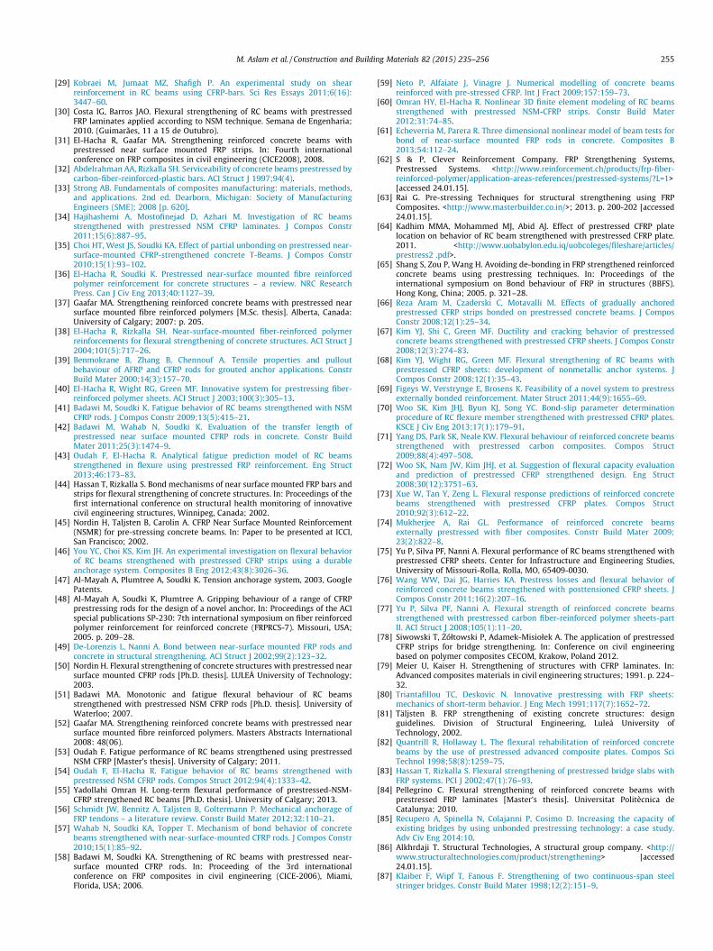
M. Aslam et al. / Construction and Building Materials 82 (2015) 235–256 255
[29] Kobraei M, Jumaat MZ, Shafigh P. An experimental study on shearreinforcement in RC beams using CFRP-bars. Sci Res Essays 2011;6(16):3447–60.
[30] Costa IG, Barros JAO. Flexural strengthening of RC beams with prestressedFRP laminates applied according to NSM technique. Semana de Engenharia;2010. (Guimarães, 11 a 15 de Outubro).
[31] El-Hacha R, Gaafar MA. Strengthening reinforced concrete beams withprestressed near surface mounted FRP strips. In: Fourth internationalconference on FRP composites in civil engineering (CICE2008), 2008.
[32] Abdelrahman AA, Rizkalla SH. Serviceability of concrete beams prestressed bycarbon-fiber-reinforced-plastic bars. ACI Struct J 1997;94(4).
[33] Strong AB. Fundamentals of composites manufacturing: materials, methods,and applications. 2nd ed. Dearborn, Michigan: Society of ManufacturingEngineers (SME); 2008 [p. 620].
[34] Hajihashemi A, Mostofinejad D, Azhari M. Investigation of RC beamsstrengthened with prestressed NSM CFRP laminates. J Compos Constr2011;15(6):887–95.
[35] Choi HT, West JS, Soudki KA. Effect of partial unbonding on prestressed near-surface-mounted CFRP-strengthened concrete T-Beams. J Compos Constr2010;15(1):93–102.
[36] El-Hacha R, Soudki K. Prestressed near-surface mounted fibre reinforcedpolymer reinforcement for concrete structures – a review. NRC ResearchPress. Can J Civ Eng 2013;40:1127–39.
[37] Gaafar MA. Strengthening reinforced concrete beams with prestressed nearsurface mounted fibre reinforced polymers [M.Sc. thesis]. Alberta, Canada:University of Calgary; 2007: p. 205.
[38] El-Hacha R, Rizkalla SH. Near-surface-mounted fiber-reinforced polymerreinforcements for flexural strengthening of concrete structures. ACI Struct J2004;101(5):717–26.
[39] Benmokrane B, Zhang B, Chennouf A. Tensile properties and pulloutbehaviour of AFRP and CFRP rods for grouted anchor applications. ConstrBuild Mater 2000;14(3):157–70.
[40] El-Hacha R, Wight RG, Green MF. Innovative system for prestressing fiber-reinforced polymer sheets. ACI Struct J 2003;100(3):305–13.
[41] Badawi M, Soudki K. Fatigue behavior of RC beams strengthened with NSMCFRP rods. J Compos Constr 2009;13(5):415–21.
[42] Badawi M, Wahab N, Soudki K. Evaluation of the transfer length ofprestressed near surface mounted CFRP rods in concrete. Constr BuildMater 2011;25(3):1474–9.
[43] Oudah F, El-Hacha R. Analytical fatigue prediction model of RC beamsstrengthened in flexure using prestressed FRP reinforcement. Eng Struct2013;46:173–83.
[44] Hassan T, Rizkalla S. Bond mechanisms of near surface mounted FRP bars andstrips for flexural strengthening of concrete structures. In: Proceedings of thefirst international conference on structural health monitoring of innovativecivil engineering structures, Winnipeg, Canada; 2002.
[45] Nordin H, Taljsten B, Carolin A. CFRP Near Surface Mounted Reinforcement(NSMR) for pre-stressing concrete beams. In: Paper to be presented at ICCI,San Francisco; 2002.
[46] You YC, Choi KS, Kim JH. An experimental investigation on flexural behaviorof RC beams strengthened with prestressed CFRP strips using a durableanchorage system. Composites B Eng 2012;43(8):3026–36.
[47] Al-Mayah A, Plumtree A, Soudki K. Tension anchorage system, 2003, GooglePatents.
[48] Al-Mayah A, Soudki K, Plumtree A. Gripping behaviour of a range of CFRPprestressing rods for the design of a novel anchor. In: Proceedings of the ACIspecial publications SP-230: 7th international symposium on fiber reinforcedpolymer reinforcement for reinforced concrete (FRPRCS-7). Missouri, USA;2005. p. 209–28.
[49] De-Lorenzis L, Nanni A. Bond between near-surface mounted FRP rods andconcrete in structural strengthening. ACI Struct J 2002;99(2):123–32.
[50] Nordin H. Flexural strengthening of concrete structures with prestressed nearsurface mounted CFRP rods [Ph.D. thesis]. LULEÅ University of Technology;2003.
[51] Badawi MA. Monotonic and fatigue flexural behaviour of RC beamsstrengthened with prestressed NSM CFRP rods [Ph.D. thesis]. University ofWaterloo; 2007.
[52] Gaafar MA. Strengthening reinforced concrete beams with prestressed nearsurface mounted fibre reinforced polymers. Masters Abstracts International2008: 48(06).
[53] Oudah F. Fatigue performance of RC beams strengthened using prestressedNSM CFRP [Master’s thesis]. University of Calgary; 2011.
[54] Oudah F, El-Hacha R. Fatigue behavior of RC beams strengthened withprestressed NSM CFRP rods. Compos Struct 2012;94(4):1333–42.
[55] Yadollahi Omran H. Long-term flexural performance of prestressed-NSM-CFRP strengthened RC beams [Ph.D. thesis]. University of Calgary; 2013.
[56] Schmidt JW, Bennitz A, Taljsten B, Goltermann P. Mechanical anchorage ofFRP tendons – a literature review. Constr Build Mater 2012;32:110–21.
[57] Wahab N, Soudki KA, Topper T. Mechanism of bond behavior of concretebeams strengthened with near-surface-mounted CFRP rods. J Compos Constr2010;15(1):85–92.
[58] Badawi M, Soudki KA. Strengthening of RC beams with prestressed near-surface mounted CFRP rods. In: Proceeding of the 3rd internationalconference on FRP composites in civil engineering (CICE-2006), Miami,Florida, USA; 2006.
[59] Neto P, Alfaiate J, Vinagre J. Numerical modelling of concrete beamsreinforced with pre-stressed CFRP. Int J Fract 2009;157:159–73.
[60] Omran HY, El-Hacha R. Nonlinear 3D finite element modeling of RC beamsstrengthened with prestressed NSM-CFRP strips. Constr Build Mater2012;31:74–85.
[61] Echeverria M, Parera R. Three dimensional nonlinear model of beam tests forbond of near-surface mounted FRP rods in concrete. Composites B2013;54:112–24.
[62] S & P, Clever Reinforcement Company. FRP Strengthening Systems,Prestressed Systems. <http://www.reinforcement.ch/products/frp-fiber-reinforced-polymer/application-areas-references/prestressed-systems/?L=1>[accessed 24.01.15].
[63] Rai G. Pre-stressing Techniques for structural strengthening using FRPComposites. <http://www.masterbuilder.co.in/>; 2013. p. 200-202 [accessed24.01.15].
[64] Kadhim MMA, Mohammed MJ, Abid AJ. Effect of prestressed CFRP platelocation on behavior of RC beam strengthened with prestressed CFRP plate.2011. <http://www.uobabylon.edu.iq/uobcoleges/fileshare/articles/prestress2 .pdf>.
[65] Shang S, Zou P, Wang H. Avoiding de-bonding in FRP strengthened reinforcedconcrete beams using prestressing techniques. In: Proceedings of theinternational symposium on Bond behaviour of FRP in structures (BBFS).Hong Kong, China; 2005. p. 321–28.
[66] Reza Aram M, Czaderski C, Motavalli M. Effects of gradually anchoredprestressed CFRP strips bonded on prestressed concrete beams. J ComposConstr 2008;12(1):25–34.
[67] Kim YJ, Shi C, Green MF. Ductility and cracking behavior of prestressedconcrete beams strengthened with prestressed CFRP sheets. J Compos Constr2008;12(3):274–83.
[68] Kim YJ, Wight RG, Green MF. Flexural strengthening of RC beams withprestressed CFRP sheets: development of nonmetallic anchor systems. JCompos Constr 2008;12(1):35–43.
[69] Figeys W, Verstrynge E, Brosens K. Feasibility of a novel system to prestressexternally bonded reinforcement. Mater Struct 2011;44(9):1655–69.
[70] Woo SK, Kim JHJ, Byun KJ, Song YC. Bond-slip parameter determinationprocedure of RC flexure member strengthened with prestressed CFRP plates.KSCE J Civ Eng 2013;17(1):179–91.
[71] Yang DS, Park SK, Neale KW. Flexural behaviour of reinforced concrete beamsstrengthened with prestressed carbon composites. Compos Struct2009;88(4):497–508.
[72] Woo SK, Nam JW, Kim JHJ, et al. Suggestion of flexural capacity evaluationand prediction of prestressed CFRP strengthened design. Eng Struct2008;30(12):3751–63.
[73] Xue W, Tan Y, Zeng L. Flexural response predictions of reinforced concretebeams strengthened with prestressed CFRP plates. Compos Struct2010;92(3):612–22.
[74] Mukherjee A, Rai GL. Performance of reinforced concrete beamsexternally prestressed with fiber composites. Constr Build Mater 2009;23(2):822–8.
[75] Yu P, Silva PF, Nanni A. Flexural performance of RC beams strengthened withprestressed CFRP sheets. Center for Infrastructure and Engineering Studies,University of Missouri-Rolla, Rolla, MO, 65409-0030.
[76] Wang WW, Dai JG, Harries KA. Prestress losses and flexural behavior ofreinforced concrete beams strengthened with posttensioned CFRP sheets. JCompos Constr 2011;16(2):207–16.
[77] Yu P, Silva PF, Nanni A. Flexural strength of reinforced concrete beamsstrengthened with prestressed carbon fiber-reinforced polymer sheets-partII. ACI Struct J 2008;105(1):11–20.
[78] Siwowski T, _Zółtowski P, Adamek-Misiołek A. The application of prestressedCFRP strips for bridge strengthening. In: Conference on civil engineeringbased on polymer composites CECOM, Krakow, Poland 2012.
[79] Meier U, Kaiser H. Strengthening of structures with CFRP laminates. In:Advanced composites materials in civil engineering structures; 1991. p. 224–32.
[80] Triantafillou TC, Deskovic N. Innovative prestressing with FRP sheets:mechanics of short-term behavior. J Eng Mech 1991;117(7):1652–72.
[81] Täljsten B. FRP strengthening of existing concrete structures: designguidelines. Division of Structural Engineering, Luleå University ofTechnology, 2002.
[82] Quantrill R, Hollaway L. The flexural rehabilitation of reinforced concretebeams by the use of prestressed advanced composite plates. Compos SciTechnol 1998;58(8):1259–75.
[83] Hassan T, Rizkalla S. Flexural strengthening of prestressed bridge slabs withFRP systems. PCI J 2002;47(1):76–93.
[84] Pellegrino C. Flexural strengthening of reinforced concrete beams withprestressed FRP laminates [Master’s thesis]. Universitat Politècnica deCatalunya; 2010.
[85] Recupero A, Spinella N, Colajanni P, Cosimo D. Increasing the capacity ofexisting bridges by using unbonded prestressing technology: a case study.Adv Civ Eng 2014:10.
[86] Alkhrdaji T. Structural Technologies, A structural group company. <http://www.structuraltechnologies.com/product/strengthening> [accessed24.01.15].
[87] Klaiber F, Wipf T, Fanous F. Strengthening of two continuous-span steelstringer bridges. Constr Build Mater 1998;12(2):151–9.
256 M. Aslam et al. / Construction and Building Materials 82 (2015) 235–256
[88] Taha MMR, Shrive NG. New concrete anchors for carbon fiber-reinforcedpolymer post-tensioning tendons? Part 2: development/experimentalinvestigation. ACI Struct J 2003;100(1):96–104.
[89] Klaiber FW, Dunker KF, Wipf TJ, Sanders WW. Methods of strengtheningexisting highway bridges. Transportation Research Board 1987; Book293.
[90] Emmons PH. Concrete repair and maintenance illustrated. Problem Analysis.Repair Strategy. Techniques. Galgotia Publication Pvt. Ltd.; 2001.
[91] Elrefai A, West JS, Soudki KA. Fatigue of reinforced concrete beamsstrengthened with externally post-tensioned CFRP tendons. Constr BuildMater 2012;29:246–56.
[92] Elrefai A, West JS, Soudki KA. Effect of overloading on fatigue performance ofreinforced concrete beams strengthened with externally post-tensionedcarbon-fibre-reinforced polymer tendons. Can J Civ Eng 2008;35(11):1294–307.
[93] Chen S, Wang X, Jia Y. A comparative study of continuous steel–concretecomposite beams prestressed with external tendons: experimentalinvestigation. J Constr Steel Res 2009;65(7):1480–9.
[94] Matta F, Nanni A, Abdelrazak A, Gremel D. Externally post-tensioned carbonFRP bar system for deflection control. Constr Build Mater 2009;23(4):1628–39.
[95] Picard A, Massicotte B, Bastion J. Relative efficiency of external prestressing. JStruct Eng 1995;121(12):1832–41.
[96] El-Refai AM. Monotonic and fatigue flexural performance of RC beamsstrengthened with externally post-tensioned CFRP tendons [Ph.D. thesis].University of Waterloo; 2007.
[97] Grace NF, Abdel-Sayed G. Behavior of externally draped CFRP tendons inprestressed concrete bridges. PCI J 1998;43(5):88–101.
[98] Stoll F, Saliba JE, Casper LE. Experimental study of CFRP-prestressed high-strength concrete bridge beams. Compos Struct 2000;49(2):191–200.
[99] Tan KH, Ng CK. Effects of deviators and tendon configuration on behavior ofexternally prestressed beams. ACI Struct J 1997;94(1):13–22.
[100] Matupayont S. Loss of Tendon’s eccentricity in external prestressed concretebeam. Proc JCI 1994;16(2):1033–8.
[101] Harajli M, Khairallah N, Nassif H. Externally prestressed members: evaluationof second-order effects. J Struct Eng 1999;125(10):1151–61.
[102] El Aziz AFM. Non-linear analysis of concrete beams prestressed and post-tensioned with carbon fiber reinforced polymer (CFRP) bars [Ph.D. thesis].University of Windsor, 2006.
[103] Fathelbab FA, Ramadan MS, Al-Tantawy A. Finite element modelling ofstrengthened simple beams using FRP techniques: a parametric study. ConcrRes Lett 2011;2(2):228–40.