2009 Dunkman - Bursting and Spalling in Pretensioned U-Beams
DESIGN CONSIDERATION FOR PRETENSIONED
PRESTRESSED BEAMS
I 2 K. Maruyama and S. R Izka II a
ABSTRACT
The use of welded wire fabric as shear reinforcement lias become popular among precast concrete Manufacturers because of its relative ease of placement and saving of tiMe and money. This paper summarizes tIle results of the first phase of a comprellensive research program designed to Investigate the Influence and e(fecllveness of welded wire (abric as shear reinforcement as compared to commonly used conventional stirrups.
Eleven pretensIoned preslressed single lee beams wIlh Identical flexur.1 reinforceMent and shear span-to-depth ratio were tested. Nine of them were loaded statically up to (allure, and two were under cyclic loading. In addition, two non-pretensioned beams wer. tested under stat Ie loadIng.
Test results revealed a COMmon premature failure for nine beams tested staticaiiy due to siippage of the prestressing strands. The ioad ievei at slippage was conslderabiy iess than that predicted using the current codes' approach. The slippage significantly Influenced the shear failure mode for these categories of beaMS. The effects of the different types of ~hear reinforcement on the crack behavior. overall deformation, shear behavior and ultimate strength are discussed.
Based on the test resuJts, a mechanism to describe the overall bel13vior of the beam is proposed, and practical considerations and design recommendations are presented.
I Assocl.te Professor, Technological University of Nag.ok.,Nagaoka,Nllgata,
2 J.p.n. Associate Professor, Unlvers Ity of ~anitoba, ";nnlpeg, "anltob •.
2
I NTllODUCTl ON
In the last few decades precast concrete structural members have become very popular In the construction field due to the saving of construction time and better quality control. The commonly used croSSsectIons 01 the beams Include mainly the thin-webbed tee and channel section. Because of the narrow webs, the use of conventional closed hoop stirrups Is Inconvenient and time-consuming. ~elded wire labrlc ( ~WF ) as shear relnrorce~ent Is an economical alternative and has become very popular wIth the precast concrete manulacturers due to Its relatIve ease
01 pI.cement .nd saving 01 c.stlng time.
~elded wire labrlc has been used In concrete Industries lor many years, especially In concrete slabs, pipes and walls. It has demon-strated very good perforunce In controll Ing cracking and prevent Ing deterioration alter cracking. There are, however, very lew published studies available with regard to the use 01 welded wire I.brlc as shear
relnforce.ent in beams.
Robertson and Durranl (1985) ex ... lned the el[ectlveness o[ welded ~Ire fabric as shear reinforcement In prestressed concrete single Tbeams. Leonhardt and \/alther (1965), Ilaskln (1982) did the similar work using reinforced concrete single T-beams. Those studies are mainly concerned with anchorage of welded wire fabric in terms of crack behavior and ultimate she .. strength. The results assured that the PCI/WRI Ad lIoc Comalttee report (1980) or ACI code provision (1983) are su[[lelent [or
anchorage of welded wire labrlc.
T.ylor .nd EI-lIamMas I (1980) c.rr led out the test program on the ellectlveness 01 velded wire [abrlc lor controlling the shear crack behavior of reinforced concrete T-beams.
Because of the COMplexity of general shear mechanism, it must require a lot 01 extensive works to verl[y the ellectlveness 01 welded wire labrlc as shear relnlorcement. Mirza and MacGregor (1981) pointed out the potential probleM 01 welded wire labrlc In its less ductility. Less ductile property 01 welded wire I.brlc may Influence the shear behavior under latlgue loading.
As ~o design of pretensioned prestressed concrete beams, tile development length 01 strands should be reconsidered when the shear behavior Is dominant. Truss analogy (Thurllmnn et a!. 1976; and Collins et .1. 1980) reveals that shear lorce produces addltlon.1 tensile [orce In longitudinal relnlorcuent. Furthermore. large shear cracks should occur near ultimate stage, and th~se cracks must c\,ange the stress distribution In prestressing strands. This Implies that the current code specilication for the development length o[ strand (CAN3-A23.3-M84; 1984) may be Insullielent.
3
Object Ives
The objectives 01 this study are sum.arlzed as follows;
I) Using the pretensioned prestressed single tee beams of which shape and dimension are similar to those of cOMmercial products, the effectiveness of welded wire fabric as shear reinforcement was examlned in comparison
with convent ional st irrups.
2) As the shear span-to-depth ratio was small, the shear crack should influence the overall behavior 01 beams. The second objective 01 this study is to propose a mechanism to describe the overall behavior 01 the beaMS and the Influence of shear cracking on the deterioration of bond stresses causing premature slippage of the prestressing strands.
3) Based on the test results and the proposed Mechanism. practical considerations and design recommendations are presented.
EXPERIMENTAL PROGRAM
The experimental program ~as designed mainlY to study the behavior 01 the thin-webbed pretensioned prestressed concrete beams with dillerent types 01 shear reinforcement In a low range 01 shear span-to-depth ratio. The load was applied statically up to failure. All other para.eters believed to alfect the shear behaviors were kept Identical except the type of shear reinforcement configuratIon.
In order to examine the Inlluence of bond characteristics between prestressing strand and concrete on the failure Mode, the non-prestressed beams were also lested. In addition, a couple of pretenstoned beams were cyclically loaded at a load level 01 shear crack Initiation.
Test Specimen
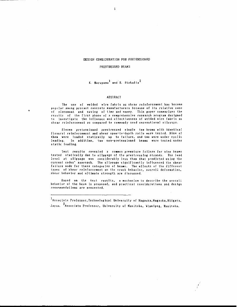
fig. 1 shows the shape and dimension of the test specimen. All thirteen beams were 3500 mm long with 650 mm wide flange, 490 mm overall depth, a flange thickness 01 60 mm, and a variable web width of 80 mm to 140 .m. The be.ms were tested at a span of 3000 mm with two point loading and a constant aid value of 2.69.
The longitudinal tension relnlorce.ents were two 15 M delormed bars and two 13 mm 7-wlre stress-relleved prestressing strands. T~o"3 (9.5 mm) deformed bars were used as longitudinal co_pression reinforcements. The tension reinforcement ratio (p=(As+Ap)/bd) is 1. 24 ". The 15 N bars were anchored using standard 90 degree bends at the ends 01 the beams with a side cover of 25 Mm. The development length of the strand lor this beam was 1400 .m. There was no special treat.ent for the end regions of the beam to Improve the bond and anchorage strength. This may be 01 question. The details are discussed In the later chapter.
4
(mm)
~ .. I ,
Ln I Ln M I ,
I Ln - tt:.: ~-- --- -::~------~---:.-- -~--~.:=:: It')
>-= I~ .
g t 1150 350
3500
650 ~-------------------
2-13 bars
-- 2 -15M bars
Fig. I Test Specl.en
5
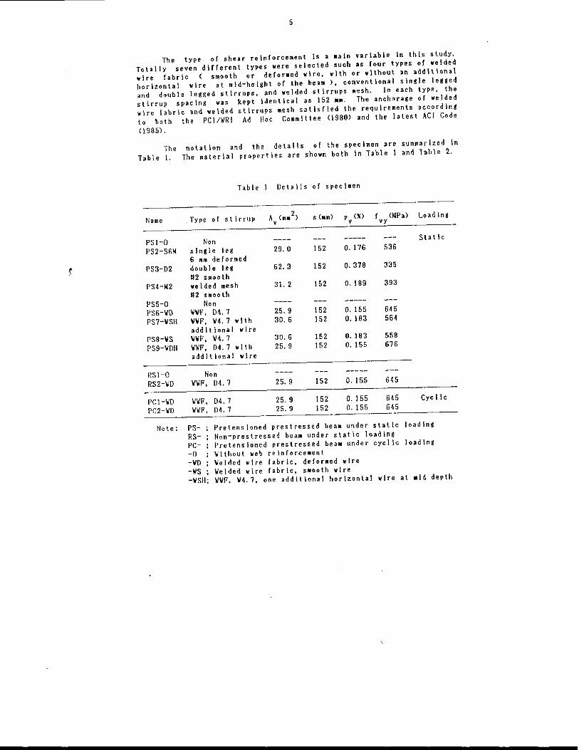
The type 01 shear relnlorcement Is a .aln variable In this study. Totally seven dillerent types were selected such as lour types 01 welded wire labrlc ( smooth or deforMed wire. with or without an additional horizontal wire at mid-height of the beam ). conventional single legged and double legged stirrups, and welded stirrups lIesh. In each type, the stirrup spacing was kept Identical as 152 ••. The anchorage 01 welded wire I.brlc .nd welded stirrups mesh satisfied the requirements according to both the PCI/\lRI Ad 1I0c Coomlttee (1980) and the latest ACI Code
(1985) .
The T.ble 1.
Name
PS1-0 PS2-S6M
PS3-D2
PS4-f.(2
PS5-0 PS6-\l1) PS7-IISII
PS8-\IS PS9-\l1l1l
RSI-O RS2-\l0
PCI-IIO pe2-1I0
Note:
not.tlon and the details of the specimen are summarized In The material properties are shown both In Table I and Table 2.
Table 1 Details of specimen
Type of st Irrup s (n) p (%) f (~Pa) Load Ing v vy
Non single leg 6 am deformed double leg "2 smooth welded mesh "2 smooth
Non \1\/1'. 04.7 11\11'. 114.7 with addlt lonal wire \IIII'. 114.7 '0'\11'. 04.7 with additional wire
Non WI'. D4.7
W\lF. 04.7 W\II'. D4. 7
29.0
62.3
31. 2
25.9 30.6
30.6 25.9
25. 9
25. 9 25.9
152
152
152
152 152
152 152
152
152 152
O. 176
O. 378
O. 189
O. 155 O. 183
O. ) 83 O. ) 55
O. 155
O. 155 O. ISS
536
335
393
645 564
558 676
645
645 645
Static
Cyc lie
PSRSPC-0
Pretensloned prestressed beam under static loading Non-prestressed beam under static loading Pretens ioned prestressed bea. under cyclic loading ~lthout web reinforce.ent
-\/0 -\IS -\ISH;
lIelded wire fabric. deforoed wire \lelded wire fabric. s.ooth wire \/\11'. \/4.7. one additional horizontal wire at .Id depth
6
Prestressing
The strands were stressed one by one with the help of a hydraulic Jack. The applied Jacking force was measured by Means of load cells and electrical resistance strain gages attached to the strands.
The prestress force was applied at the eighth day by cutting the prestressing strands at the ends with an oxyacetylene torch. The co.presslve strength of concrete at that age was about 30 MPa while the no.lnal strength at 28 daYs of age was 40 MPa. The strain In strands was monitored by a strain Indicator up to the testing day.
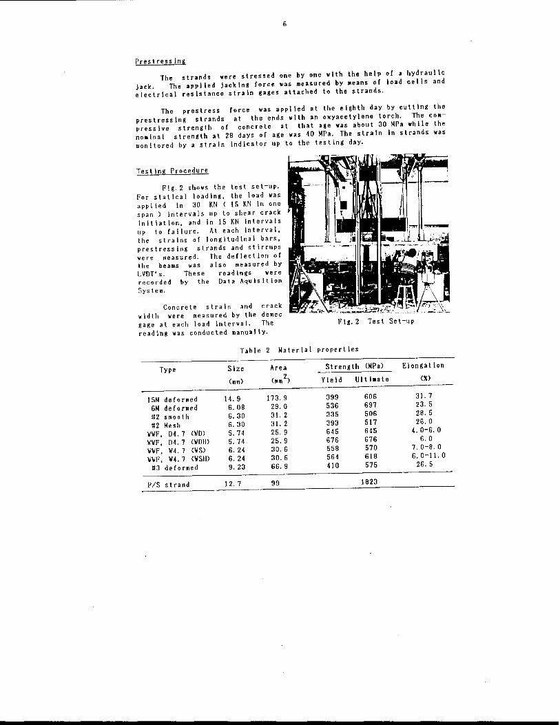
Testing Procedure
Flg.2 shows the test set-up. For statical loading, the load was appl ied In 30 KN ( 15 KN In one span) intervals up to shear crack inltl.tlon, .nd In 15 KN Intervals up to failure. At each Interval, the strains of longitudinal bars, prestressing strands and stirrups were measured. The deflection of the beams was also measured by LVDT·s. These readings were recorded by the Data Aqulsition Sys tem.
Concrete strain and crack widtll were measured by tile demec gage at each load interval. The reading was conducted manually.
Table 2 Material
Type Size Area
(mm) (mm 2)
15M deformed 14. 9 173.9
6M deformed 6. OB 29. 0
"2 smooth 6. 30 31. 2 "2 Mesh 6. 30 31. 2
\lIIF, 04. 7 (WO) 5. 74 25. 9 \/\11', 04. 7 (WOII) 5.74 25. 9 \/\IF, 114. 1 (WS) 6. 24 30. 6 \IIII', W4.7 (WSm 6. 24 30.6
"3 deformed 9.23 66.9
PIS strand 12.7 99
Flg.2 Test Set-up
properties
Strength (lIPa) Elongation
Yield \JllI .. te eo
399 606 31. 7 536 697 23. 5 335 506 2B. 5 393 517 26. 0 645 645 4.0-6.0 676 676 6.0 558 570 1.0-8.0 564 618 6. 0-11. 0 410 575 26. 5
1823
1
The simiiar procedure ~as done for the case of cyci ic loading. The maximum load ievei was 180 KN at which the first shear crack initiated,
and lhe mlnlmu. load level was 50 KN.
TEST RESULTS AND DISCUSSION
Prestress Losses
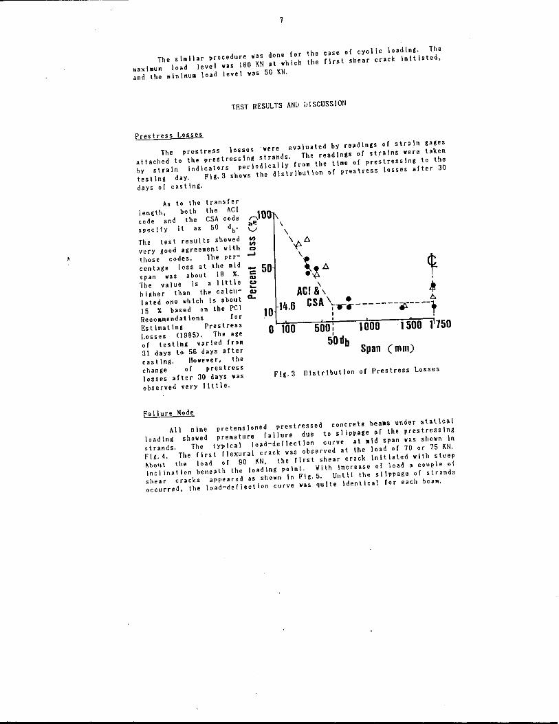
The prestress losses were evaluated by readings of strain gages attached to the prestressing strands. The readings of strains were taken by strain Indicators periodically from the lime of prestressing to the test Ing day. Flg.3 shows the distribution of prestress losses after 30
days of casllng.
As to the length, both code and the specify It as
transfer the AC I CSA code
50 db'
The tesl resulls showed
r"\10 .,e V ...
very good agreement with :: those codes. The per- -' centage loss at the mid span was about 18 X. -C 50 The value Is a little higher than the calculated one which Is about 15 % b.sed on lhe PCI Reco.mendatlons for Estimating Prestress Losses (1985). The age of testing varied from 31 days to 56 days after casting. I!owever, the change of prestress losses after 30 days was observed very little.
Failure 1I0de
II> ... ... ... a..
o 100
Fig.3
500 I 1000 1 500 1750 I
50db Span (mm)
Distribution of Prestress Losses
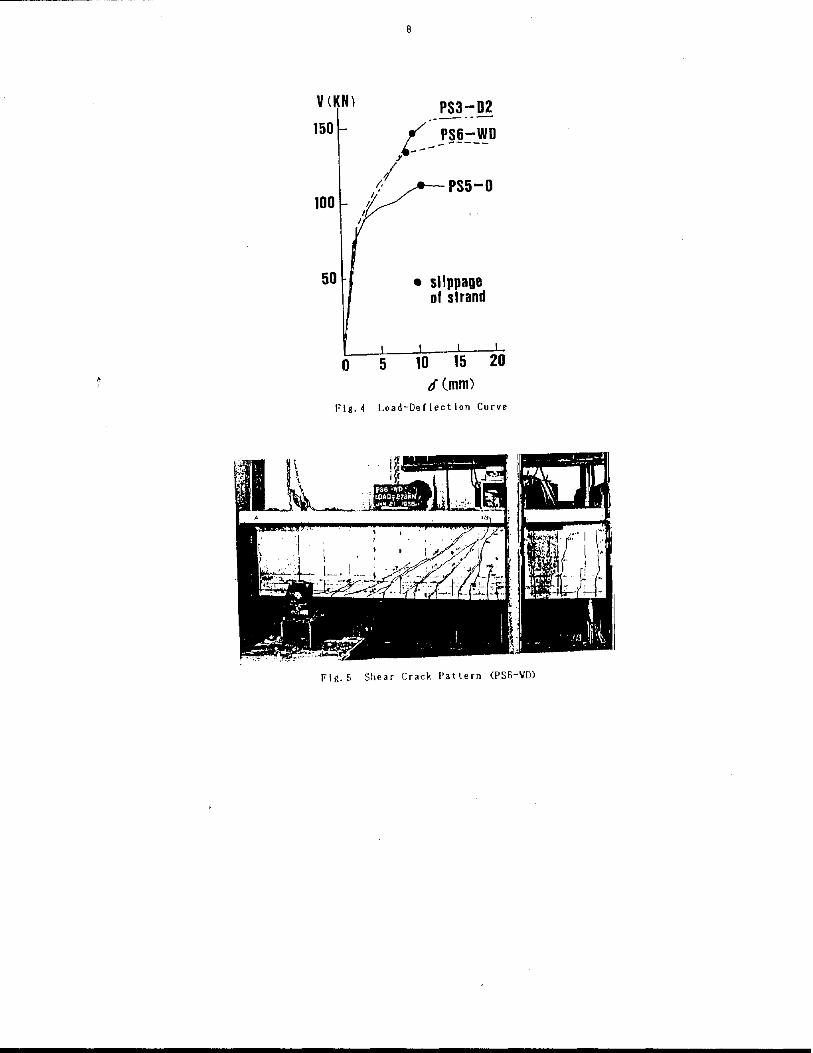
All nine pretensloned prestressed concrete beaas under statlcai loading showed premature failure due to slippage of the prestressing strands. The lyplcal load-deflection curve at .Id span ~as shown In Flg.4. The first flexural crack was observed at the load of 10 or 75 KN. About the load of 90 KN, the first shear crack Initiated with steep Incllna! Ion bene.th the loading point. \/Ith Incre.se of load a couple of shear cracks appeared as sho .. n In Fig.5. Unlll the slippage of strands occurred. the load-deflection curve was quite identical for each beam.
V(KN) 150
100
50
o
B
PS5-0
• slippage of strand
If (mm)
Flg.4 Load-Dellectlon Curve
Flg.5 Shear Crack Pattern (PS6-VD)
9
The slippage of strand was detected by the strain readings. As stated by Ghosh and Flntel (1986), the first slip does not mean the ultimate or the failure of the beam. A little more load was picked up until the maximum strength was observed. It should be noticed that after reaching the maximum load the beaM could deflect in a large amount without reduction of strength. The test was terminated by the stroke I i.lt 01 an actuator (100 mm). At this stage, the shear crack width was more than 1.0 mm \n any case. Notyithstandin& the large shear crack width. the concrete or top flange was neither punched out nor crushed.
The load at slippage was sUmMarized In Table 3. Based on the strain compatibility analysis and the equation of the development length, such as Id~O.145(fps-O.67fse)db (CSACode 1984>, the load at slippage
was evaluated as 150 KN. The test results showed lower values than tIle calculated one although the InIluence 01 the type of web relnlorcement was recognized. Referring to the shear crack pattern as shown In Fig. 5, the approximate calculation was done lor the development length and Ihe ~ load at slIppage. The result Indicated that the actual development length should be taken Irom the point where a large shear crack crossed "Ie prestressing strand, not from the point or the maximum moment appeared.
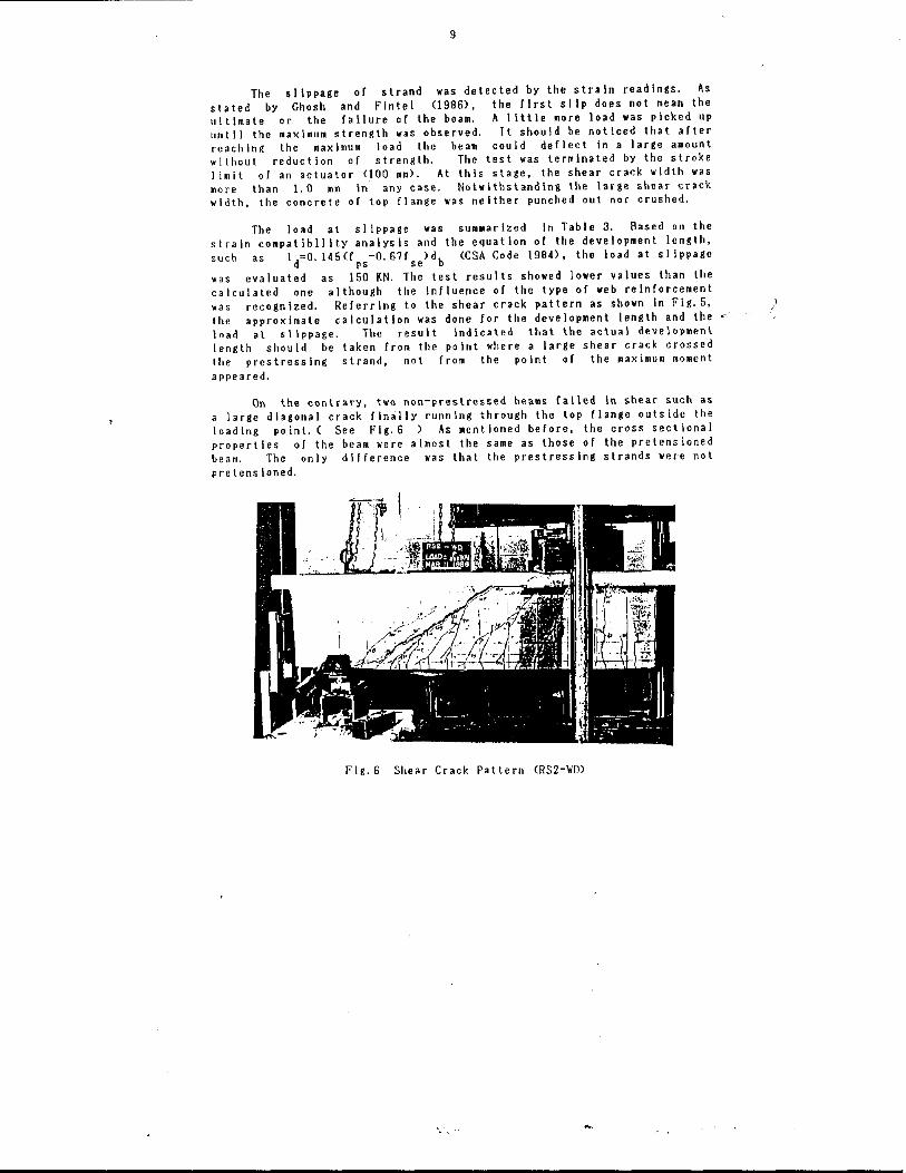
On the contrary. two non-prestressed beams failed in shear such as a large diagonal crack Iinally running through the top flange outside the loading point. ( See l'Ig.6 ) As .entioned before, the cross sectional properties of the beam were .lmost the same as those of the pretensioned beam. The only difference was that the prestressing strands were not pre tens toned.
Flg.6 Shear Crack Pattern (RS2-\I0)
10
As to the bond behavior of untensloned prestressing strand, Sal.ons and McCrate (1971) proposed the equation for the eMbedMent length of straight strand, such as L
e=0.331f s +8.00 (In.). The notation of fs
stands for the Maximum stress In the strand (ksll. As the available embedment length of the beam is 1400 om, the equation leads to that the maximum strand stress is 964 MPa. This value can be related to the applied load of li5 KN in one span according to the strain compatlbil ity analysis. The ultimate shear slrenglh was less or similar to this load as listed in Table 3.
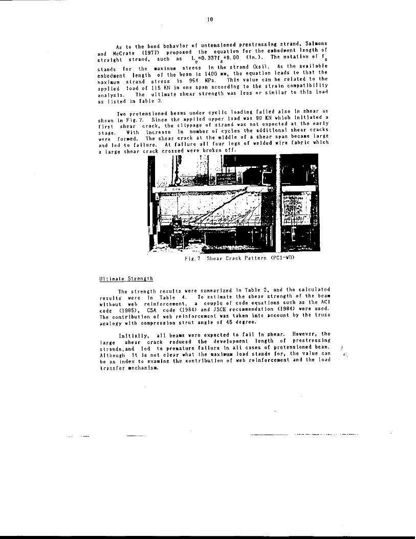
Two pretensioned beams under cyc\ ic loading failed also in shear as shown in Fig.? Since the appl ied upper load was 90 KN which initiated a first shear crack, the slippage of strand was not expected at the early slage. ~ith increase In nUMber of cycles the additlon.1 shear cracks were for.ed. The shear crack at the middle of a shear span beca.e large and led to failure. At failure all four legs of welded wire fabric which a large shear crack crossed were broken off.
Fig.? Shear Crack Pattern (pel-VDl
1I1 t imate Strength
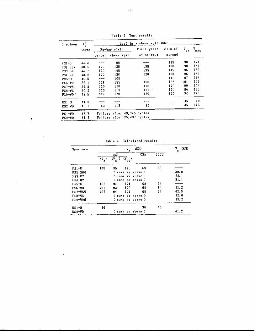
The strength results were summarized in Table 3, and the calculated resul ts were In Table 4. To est imate the shear strength of the be .. without web reinforcement, a couple of code equations such as the ACI code (1985), CSA code (1984) and JSCE reconendatlon (1984) were used. The contribution of web reinforcement was taken Into account by the truss analogy with compression strut angle of 45 degree.
Initially, all bea.s were expected to fall In shear. However, the large shear crack reduced the development length of prestressing strands,and led to pre.ature lallure In all cases of pretensloned beam. Although It is not clear what the .axl.u. load stands for, the value can be an index to examine the contribution of web relnforce.ent and the load transfer MechanisM.
Specimen f ' c (MPa)
PSI-Q 44. 4 PS2-S6M 43. 5 PS3-D2 44.1 PS4-M2 43. 2 PS5-Q 40. 5 PS6-IID 38. 1 PS7-IISH 39. 2 PS8-IIS 40. 2 PS9-IIDII 41. 5
RSI-Q 41. 3 RS2-IID 40. 1
PC1-IiD 43.1 PC2-IID 44. 4
Specimen
PS1-Q PS2-S6M PS3-D2 PS4-M2 PSS-O PS6-IID PS1-WSII PS8-IIS PS9-IIDH
RSI-Q RS2-IID
11
Table 3 Test results
Load In a shear span (KN)
Re-bar yield First yield
center shear span of stirrup
98 120 135 135 120 145 135 120 130 120
105 128 135 120 120 120 113 120 113 113 121 120 120
83 113 90
Failure after 49, 145 cycles Failure after 25,491 cycles
Table 4 Calculated results
V (KN> c
CS~ ACI, __ _ (v)(v~I-) (V )
c c cw
103
102 101 102
46
95 125 69 ( sallie as above ( same as above) ( same as above) 94 121 68 93 120 68 94 121 68
S31111e as above) ( same as above)
36 ( sallie as ahove )
JSCE
66
64 63 64
43
Slip of V cr strand
113 90 136 98 145 95 133 96 113 81 135 101 120 120 120
90 98 94
45 45
V (KN> s
38. 9 52. I 31. 1
41. 2 42. 5 42. 0 43. 2
41. 2 ------
V max
121 151 156 146 114 139 134 123 128
68 126
12
Generally, code equations give lower values of strength because they Involve the safety factor. This trend may be eMphasized for shear strength of prestressed concrete beams. Lyngberg (1976) compared some test results with the ACI code, Danish code and the theory of plasticity. lie concluded that both codes gave the lower Ii_it of the test results, and that the theory of plasticity could show the good prediction of the
ultimate shear resistance.
~ccordlng to the calculation results In Table 4, all three codes give lower shear strength than the actual shear cracking strength for preslressed bea.s. For non-prestressed beams the trend Is sl.llar. The predicted value from any code equation Is rather the shear cracking strength than the ult1m.te shear strength.
Two prestressed beams under cyclic loading were only for exa.lnlng the failure Mode at this stage. lIowever, the nu.ber of load cycle at failure was less than 50,000 for both cases. The load level of first shear crack initiation seems very high for fatigue strength.
Contribution of ~eb Reinforcement
Since the shear failure was not clearly recognized In all nine prestressed beams, the contribution of yeh reInforcement can not be read dlreclly fro. Ihe strength results. As listed In Table 3, the load at slippage of strand or the .axlmum load varied In be •• s wllh dlfferenl type of web reinforcement. The results .ay Indicate that the convenIional stirrups are beller than the welded wire f.brlcs.
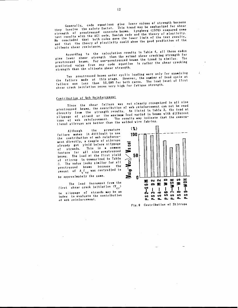
Although the premature failure makes It difficult to see the contribution of web reinforcement directly, a couple of stirrups already got yield before slippage of strands. This is COMmon feature for all nine prestressed beams. The load .t Ihe first yield 01 stirrup Is summarized In Table 3. The value looks similar for all prestressed beams because the amount· of A f was conlrolled to
v vy be approxl.ately Ihe sa.e.
The load increment fro. the
r Irs t shear crack Inltlatlon (V ) cr
to slippage of strands .ay be an
index to evaluate the contribution of web reinforcement.
(%) 100
Fig. 8
. -:.;-¥~-------~~ \
E N N = ::c Vol ::c ca CI IE
== Vol
== CI
;= f I I I I I M "'" ca r- eo en
en en en en en en en CL CL. CL. CL. CL. CL. CL.
Contribution of Stirrups
13
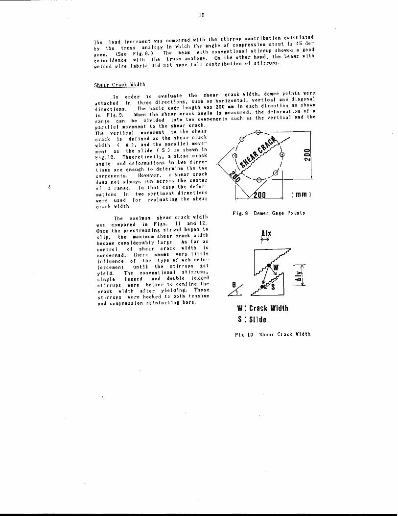
The load Increment was compared with the stirrup contribution calculated by the truss analogy In which the angle of co_pression strut Is 45 degree. (See Fig. 9.) The beam with conventional stirrup showed a good coincidence with the truss analogy. On the other hand, the bea.s with welded wire Cabrlc did not have full contribution oC stirrups.
Shear Crack Vldth
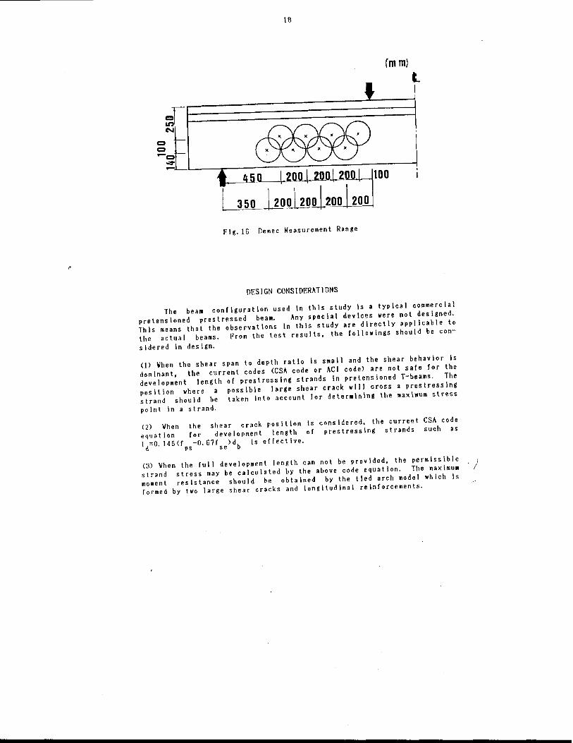
In order to evaluate the shear crack width. de.ec points were attached In three directions, such as horizontal, vertical and diagonal direct Ions. The bas Ic gage length was 200 MIl In each direct Ion as shown In Fig.9. When the shear crack angle is lIIeasured, the derormat ion of a range can be divided Into two cOMponents such as the vertical and the parallel movement to the shear crack. Tile vertical Movement to the shear crack Is deClned as the shear crack width ( ~), and the parallel Mvement as the slide ( S) as shown In Fig.l0. Theoret ically, a shear crack angle and deCormatlons In two directions are enough to determine the two components. However, a shear crack does not always run across the cenler of a range. In that case the deCormations in two pertinent directions were used for evaluating the shear crack width.
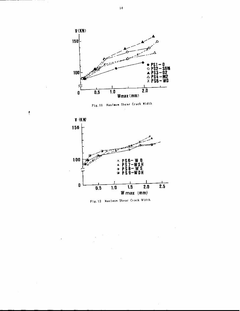
The maximum shear crack width was compared In Figs. 11 and 12. Once the prestressing strand began to slip, the .aximum shear crack width beca.e considerably large. As far as control of shear crack width Is concerned, there seeJIIS very little Influence of the type of web relnCorceMent until the stirrups got yield. The conventional stirrups, single legged and double legged stirruPs were better to confine the crack width after yIelding. These stirrups were hooked to both tension and compression reinforcing bars.
o o N
(mm)
I'lg.9 De.ec Gage Points
W: Crack Width S : Slide
Flg.10 Shear Crack ~Idth
v(KN)
150
V (KNi
J
14
I I I 0.5 1.0 2.0
Wmax tmm)
Fig.11 Maxi.uM Shear Crack Width
x PS6- W 0 & PS7-WSH () PS8-WS !<I PS9-WDH
I I I I I
0.5 1.0 1.5 2.0 2.5 Wmax (mm)
Fig. 12 Maximum She.r Crack Width
15
SHEAR RES I STI NG MEeHAN I SM
The slippage of prestressing strands prevented the prestressed beams from clear shear faIlure. However, some stirrups already got yield before slippage or strands in any beam. In spite ot large shear cracks at the maximum load, the beam could derlect without shear failure. On the other hand, unpretensloned bea~s Called in shear. These facts should be a key to consider the shear resisting mechanisM.
From the observation of failure of a beam, It can be considered that what controls the failure of the beaM Is the stress or strain condition of concrete in cOMpressIon zone. But It Is not easy to measure the strain condition of concrete because the compression zone 1s so thin and the strain Is not uniforM In the top flange.
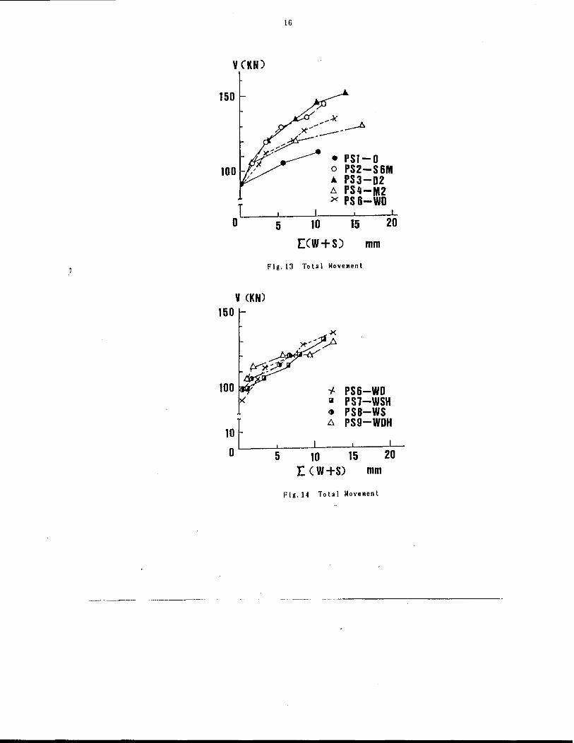
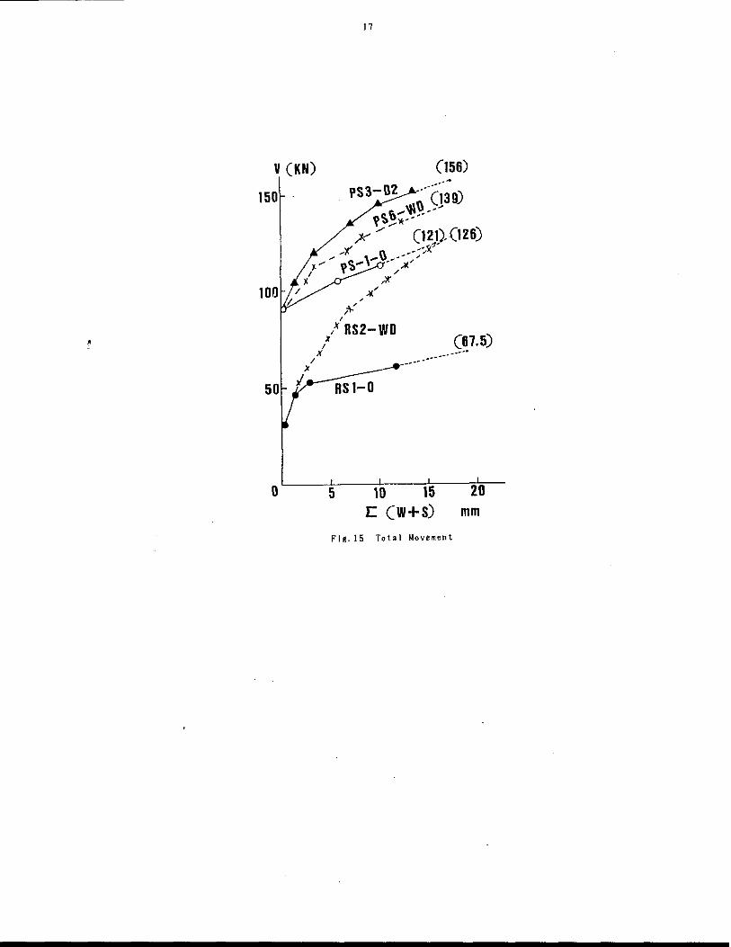
In order to exaalne the failure condition of the beam, the authors propose to consider the deformation of the web element In tension because the stress or the strain condition of concrete In cOMpression zone Must be related to the deformation of concrete In tension zone. Figs. 13-15 shows one exaMple to express the overall behavior of deformation In tension zone. The total movement }n the figure represents the summation of the vertical and the parallel Movements to the shear crack In all demec measure.ent ranges in one shear span. The de.ec ranges in the web are shown in Fig. 16.
The demec MeaSUrements could not be conducted very ne.r ultimate. Ilowever, the extrapolation of the total Movement up to the maximull load indicates that the amount of total Movement at the m.xlMum load or at failure looks similar In any beam as shown In Flg.IS. This phenomenon makes the lollowlng hypothesis possible
The stress or strain be unIque at ult imate.
should be specified by conf Ined. "
condition of concrete In compression The way how to reach the unique
how the concrete ele.ent of the
zone must condition
be ami s
As the means of reinforcement and the conf Inement of reaching ultimate.
confining concrete, longItudinal reinforceMent, web prestressing may be treated In the sa.e manner. When concrete is good, the beam can carry more load before
In comparison of prestressed beams with non-prestressed beams In Flg.15, the effectiveness of prestress on conflneNent seems constant for both beams with and without web reinforcement. The contribution of web reinforcement may be similar in prestressed beaNS and non-prestressed beams as well. The slippage of prestressing strands reduces the confinement effect and decreases the ultimate load. When the sl ippage occurred, the conventional hooked stirrups, single legged or double legged, look belter for confinement tllan any kind of welded wire fabric.
V (KN)
150
100
T o
V (KN) 150
100
JOr o
16
-~ ~",."'- ~ ,>t ___ -
~~-• PS1-0 o PS2-S6M .. PS3-02 .6. PS4-M2 x PS6-WD
I , I
5 10 15 20
[CW+S) mm
I'Ig.13 Total Moveunt
, 5
'f. PS6-WD III PS7-WSH <t PS8-WS ~ PS9-WDH
I L-ID 15 20
r. (W+S) mm
Flg.14 Total MoveMent
•
v (KN)
150
)C
/
o
x I
X /
;,:' /
I
11
/ RS2-WD
(156) .,~
Flg.15 Total Movement
III
(mm)
'-l--"''''-''--I---It 0 0
l I
Flg.16 nemec Measurement Range
nESIGN CONSIDERATIONS
The beam conllguratlon used In this study Is a typical commercial pretensloned prestressed be a.. Any special devices were not designed. This means that the observations In this study are directly applicable to the actual beams. From the test results, the lollowings should be con-
s idered in des ign.
0) ~hen the shear span to depth ratio is small and the shear behavior Is dominant, the current codes (CSA code or ACI code) are not sale lor the development length 01 prestressing strands in pretensioned T-beams. The position where a possible large shear crack will cross a prestressing strand should be taken into account lor determining the Maximum .tr •••
point in a strand.
(2) When the shear crack position is equation lor development length 01 Id=o.145(lps-O.67fse'db Is errectlve.
considered, the current CSA code prestressing strands such as
(3) When the lull development length can not be provided, the permissible ) strand stress may be calculated by the above code equation. The maximu. moment resistance should be obtained by the tied arch model which Is formed by two large shear cracks and longItudinal reinforcements.
20
REFERENCES
AMERICAN CONCRETE INSTITUTE. \985. Building Code RequIrements lor ReInforced Concrete (ACI 318M-83)' Detroit, MichIgan.
BASKIN, K. L. 1982. BehavIor of concrete T-bea .. with welded wIre fabric web reln!orcement. M.S. Thesis. University of Alberta, Edmonton,
Alberta. CANADIAN PRESTRESSED CONCRETE INSTITUTE. 19B2 ~etrlc Design ~anual,
precast and prestressed concrete. First Edition. CANADIAN STANDARDS ASSOCIATION. 1984. Design 01 Concrete Structures for
Buildings (CAN3-A23.3-MB4). Rexdale, Ontario. COLLINS, ~. P. and MITCIiELL, D. 1980 Shear and tors Ion des Ign of
prestressed and non-prestressed concrete bea.s. pel Journal. Vol.25, No.5, September-October, pp.32-)00.
GHOSH, S. K. and I'INTEL, t.I. 1986. DevelopMent length 01 prestressing strands, Including debonded strands, and allowable concrete stresses In pretensloned meMbers. PCI Journal, Vol. 31, No.5, September-
October, pp.3B-51. GROB, J. and T1IURLlMANN, B. 1916. Ultlnte strength and design of
reinforced concrete beams under bending and shear. IABSE, Publication No. 36(\1), Zurich, Switzerland, p.15.
JAPAN SOCIETY 01' CIVIL ENGINEERS. 1984. RecomMendations for limit state design of concrete structures. Concrete Library Internat\onal, No.4,
December, Tokyo, Japan. LEONHARDT, F. and \/ALTlIER, R. 1965. \lelded wire mesh as stirrup
reinforcement. shear tests of T-beaMs and anchorage tests. (Ger~an) Bautechnlk, Vol. 42, No.IO, October, EnglIsh Translotlon by". [lilger.
LYNGBERG, n. S. 1916. UltiMate shear resIstance of p.rtlall, prestressed reinforced concrete I-beams. ACI Journal, Proceedings v.n, No.4
Apr II, pp 214-222. ~IRZA, S.A. and MACGREGOR, J.G. 19B1. Strength and ductility 01
concrete slabs reinforced with welded wire labrlc. ACI Journal, Proceedings, Vol.19, No.5, pp.314-38.
PRESTRESSED CONCRETE INSTITUTE COMMITTEE ON PRESTRESS LOSSES. 19B5. RecomMendations for estl.atlng prestress losses. PCl Journal, Vol.30, No.4, July-August, pp.44-14.
PRESTRESSED CONCRETE INSTITUTE TECHNICAL ACTIVITIES CO~MITTEE' S JOINT PCI/\/RI Ad Hoc. COMMITTEE ON \lELDED \lIRE FABRIC I'OR SHEAR REIN-FORCEMENT. 1900. PCI Journal, Vol. 25, No.4, July-August, pp.32-36.
ROBERTSON, I.N. and DURRANI, A.J. 19B5. Shear strength of prestressed con~rete T-beams with welded wire fabric as shear reinforcement. Structural Research Report No. 29, Department of Civil Engineering, Rice University, Ilouston, Texas, U. S.I\. I January, plB2.
SAL~ONS, J. R. and MCCRATE, T. E. 1911. Bond characteristIcs of untens ioned prestress Ing strand. PCI Journal, Vol.22, No.1, January-
February. pp52-65. TAYLOR, M. A. and EL-HAMMASI, S. 1980.
using welded wire fabric as shear Proceed Ings V.71, No. I, pp.12-11.
\leb cracking behavior of beams re Inlorcement. ACI Journa I,
21
APPENDIX
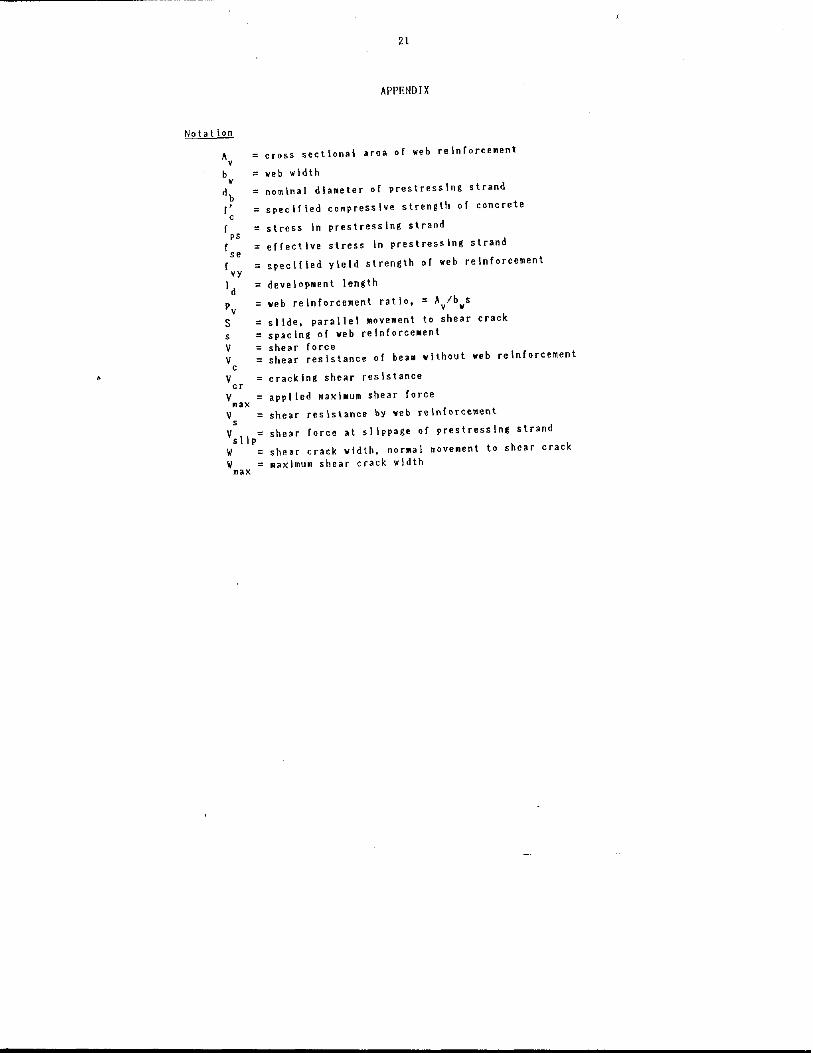
Notation
A crosS sectional area of web reinrorcement v
b = web width w
db nominal diameter of prestressing strand
(' specified compressive strength of concrete c
f = stress in prestressing strand ps
f se effective stress In prestress Ing strand
{ = specl!led yield strength of web reln!orcement vy
Id = developoent length
Pv = web reln!orcement ratio, = Av/bws
S = slide, parallel Movement to shear crack s = spacing o! web relnforce.ent V shear (orce V shear resistance of beam without web reinforcement
c V cracking shear resistance cr
Vmax
= applied maxl.um shear force
V shear resistance by yeb reinf0fcement s
Vsllp
= shear force at slippage of prestressIng strand
V shear crack width. normal movement to shear crack W .axlmurn shear crack wIdth
max