
State!Machines!! & Karnaugh!Maps! - University of the...
50
Computer Systems and Networks ECPE 170 – Jeff Shafer – University of the Pacific State Machines & Karnaugh Maps
Transcript of State!Machines!! & Karnaugh!Maps! - University of the...

ì Computer Systems and Networks ECPE 170 – Jeff Shafer – University of the Pacific
State Machines & Karnaugh Maps

Upcoming Events
ì Homework 5 -‐ Due Tuesday ì Paper submissions accepted for this assignment
(since it involves drawing Karnaugh Maps…)
Fall 2011 Computer Systems and Networks
2
Upcoming Events
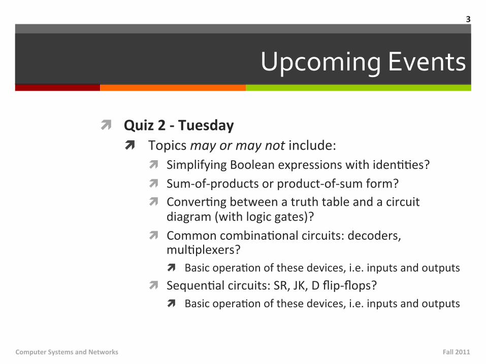
ì Quiz 2 -‐ Tuesday ì Topics may or may not include:
ì Simplifying Boolean expressions with idenMMes? ì Sum-‐of-‐products or product-‐of-‐sum form? ì ConverMng between a truth table and a circuit
diagram (with logic gates)? ì Common combinaMonal circuits: decoders,
mulMplexers? ì Basic operaMon of these devices, i.e. inputs and outputs
ì SequenMal circuits: SR, JK, D flip-‐flops? ì Basic operaMon of these devices, i.e. inputs and outputs
Fall 2011 Computer Systems and Networks
3
Recap from Last Class
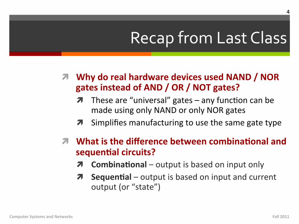
ì Why do real hardware devices used NAND / NOR gates instead of AND / OR / NOT gates? ì These are “universal” gates – any funcMon can be
made using only NAND or only NOR gates ì Simplifies manufacturing to use the same gate type
ì What is the difference between combinaNonal and sequenNal circuits? ì CombinaNonal – output is based on input only ì SequenNal – output is based on input and current
output (or “state”)
Fall 2011 Computer Systems and Networks
4

Recap from Last Class
ì What is the difference between a half-‐adder and a full-‐adder? ì Half adder adds two inputs (x, y) and produces sum
and carry-‐out ì Full adder adds three inputs (x, y, carry-‐in) and
produces sum and carry-‐out ì We build it out of two half-‐adders!
Fall 2011 Computer Systems and Networks
5
Recap from Last Class
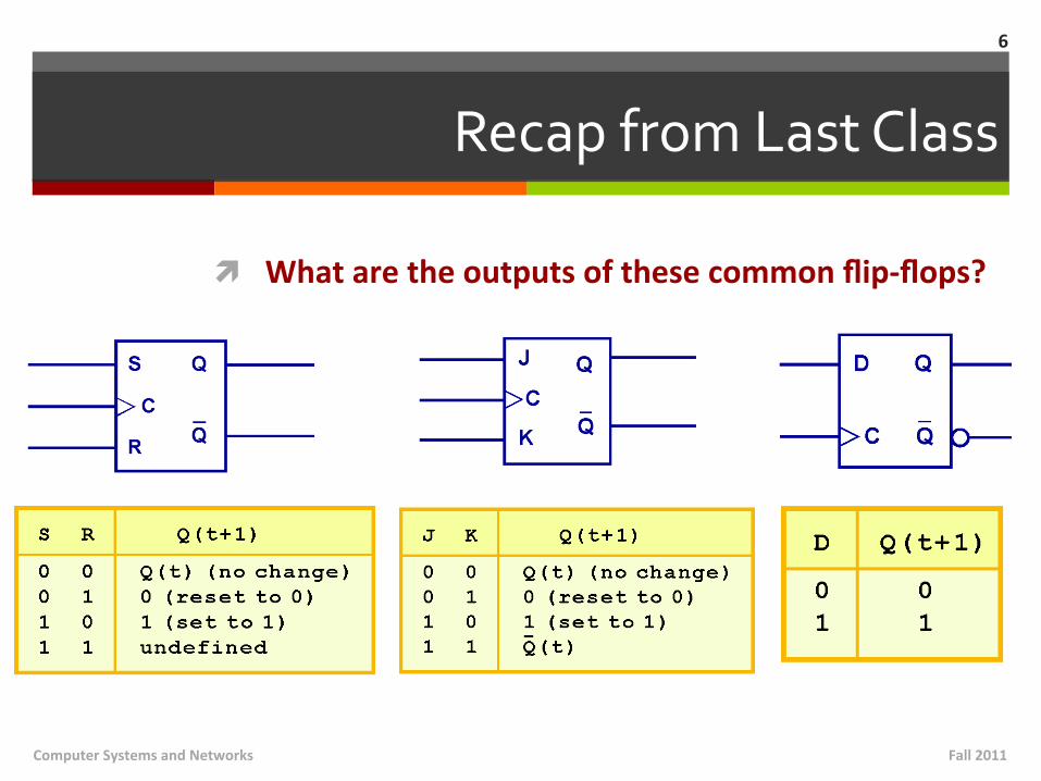
ì What are the outputs of these common flip-‐flops?
Fall 2011 Computer Systems and Networks
6

Discussion
ì Engineering lab equipment and faciliMes ì ParMally paid for from your lab fee $$ ì SuggesMons for improvement?
Fall 2011 Computer Systems and Networks
7
ì State Machines
Fall 2011 Computer Systems and Networks
8
State Machines
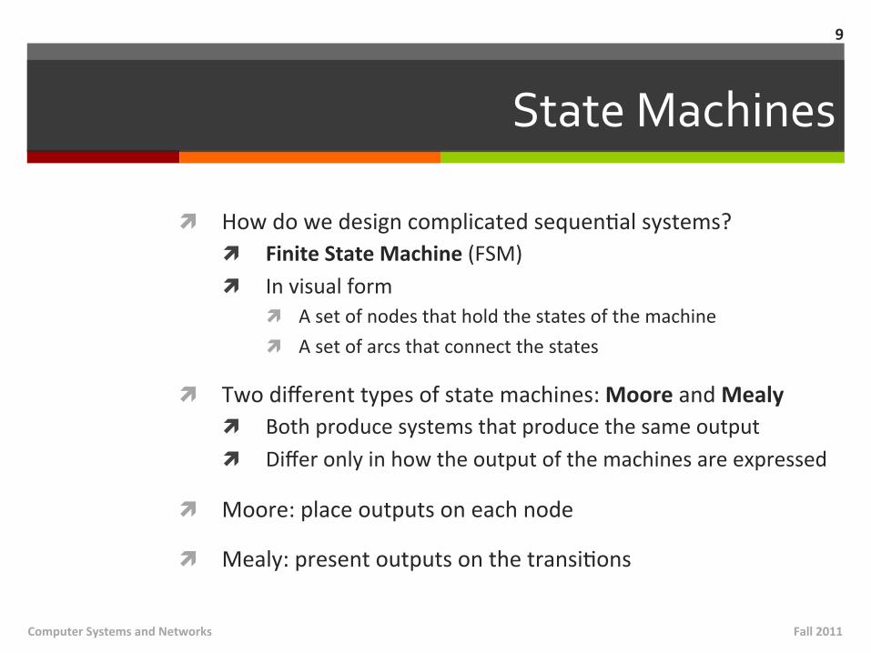
ì How do we design complicated sequenMal systems? ì Finite State Machine (FSM) ì In visual form
ì A set of nodes that hold the states of the machine ì A set of arcs that connect the states
ì Two different types of state machines: Moore and Mealy ì Both produce systems that produce the same output ì Differ only in how the output of the machines are expressed
ì Moore: place outputs on each node
ì Mealy: present outputs on the transiMons
9
Fall 2011 Computer Systems and Networks

JK Flip-‐Flop in State Machine Form
Moore FSM Mealy FSM
10
Fall 2011 Computer Systems and Networks
Output
Inputs (JK)
State
Output Inputs (JK)
State
Different Implementations
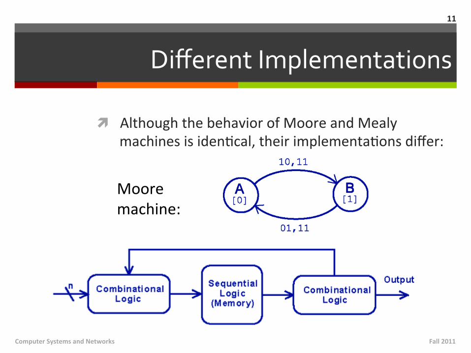
ì Although the behavior of Moore and Mealy machines is idenMcal, their implementaMons differ:
11
Moore machine:
Fall 2011 Computer Systems and Networks
Different Implementations
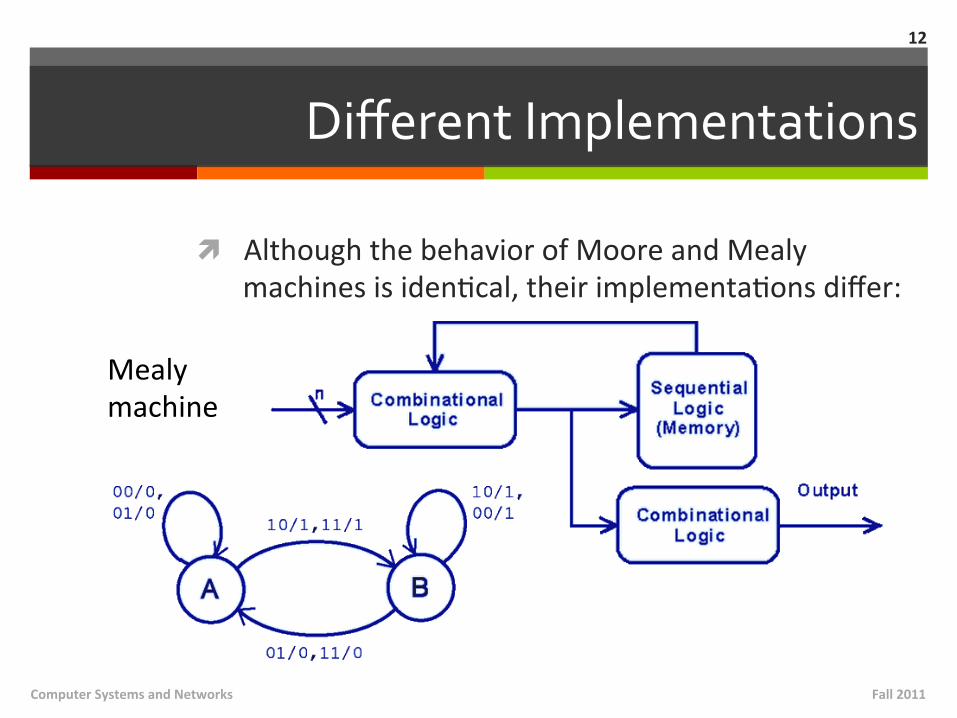
ì Although the behavior of Moore and Mealy machines is idenMcal, their implementaMons differ:
12
Mealy machine
Fall 2011 Computer Systems and Networks
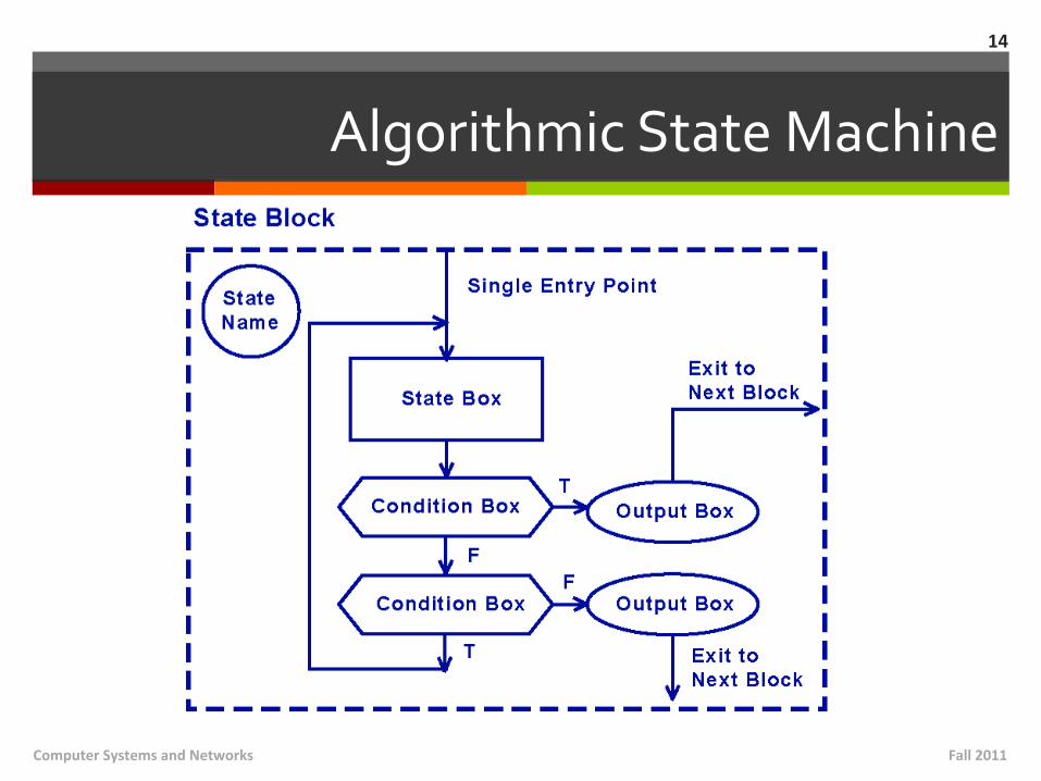
Algorithmic State Machine
ì Moore and Mealy machines are challenging to draw for complex designs ì An interacMon of numerous signals is required to
advance a machine from one state to the next
ì Alternate approach: Algorithmic State Machine ì A block diagram approach to describing digital
systems
13
Fall 2011 Computer Systems and Networks
Algorithmic State Machine
Fall 2011 Computer Systems and Networks
14
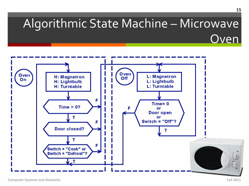
Algorithmic State Machine – Microwave Oven
Fall 2011 Computer Systems and Networks
15
Sequential Circuit Applications
ì When do I use sequenMal circuits? ì Whenever the applicaMon is “stateful” ì The next state of the machine depends on the
current state of the machine and the input
ì Stateful applicaMons requires both combinaMonal and sequenMal logic
ì Examples: Register, Memory, Counters, …
16
Fall 2011 Computer Systems and Networks
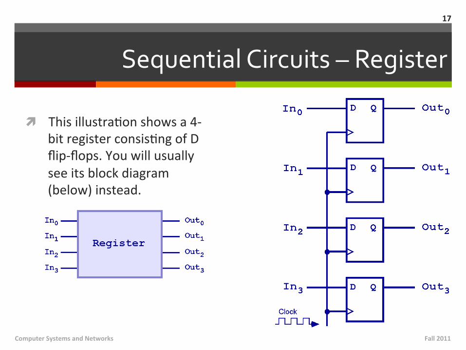
Sequential Circuits – Register
ì This illustraMon shows a 4-‐bit register consisMng of D flip-‐flops. You will usually see its block diagram (below) instead.
Fall 2011 Computer Systems and Networks
17
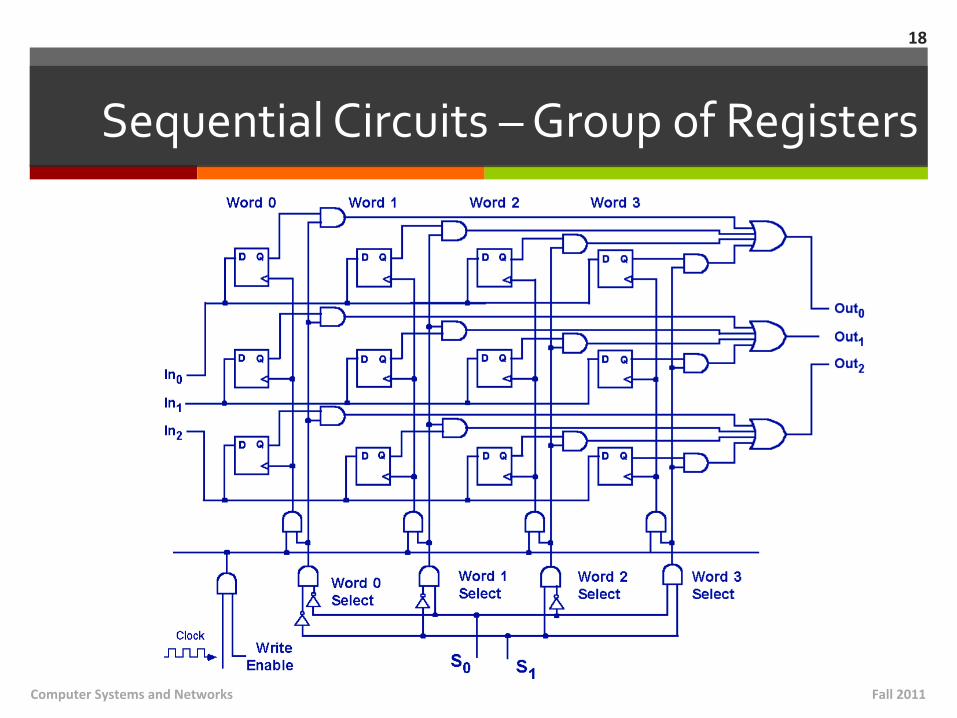
Sequential Circuits – Group of Registers
Fall 2011 Computer Systems and Networks
18
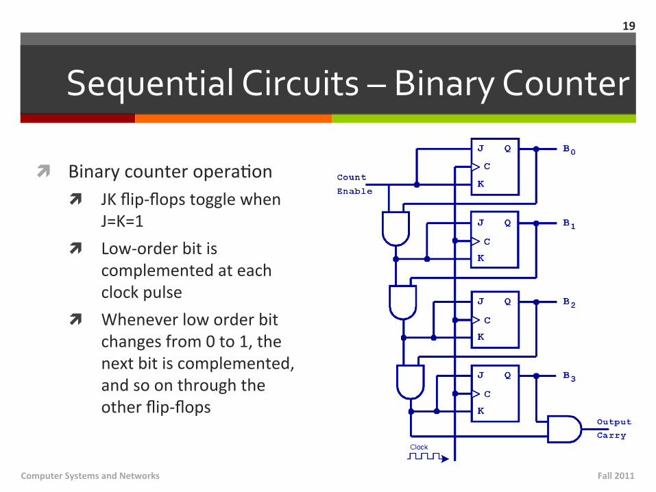
Sequential Circuits – Binary Counter
ì Binary counter operaMon ì JK flip-‐flops toggle when
J=K=1 ì Low-‐order bit is
complemented at each clock pulse
ì Whenever low order bit changes from 0 to 1, the next bit is complemented, and so on through the other flip-‐flops
Fall 2011 Computer Systems and Networks
19
Designing Circuits
ì Do designers usually lay out circuits by hand? ì No – designers today rely on specialized sogware to create
efficient circuits ì Sogware is an enabler for the construcMon of beier
hardware!
ì Many challenges in modern hardware designs ì Sheer number of gates to implement!
ì Create “building blocks” (modules) that can be quickly assembled
ì Timing constraints – Result is correct, but when is it correct? ì PropagaMon delays occur between the Mme when a circuit’s
inputs are energized and when the output is accurate and stable
20
Fall 2011 Computer Systems and Networks
ì K-‐Maps
Fall 2011 Computer Systems and Networks
21
Introduction to Karnaugh Maps
ì Chapter 3A in textbook
ì SimplificaMon of Boolean funcMons is good… ì Produces simpler (and usually faster) digital circuits
ì … but also Mme-‐consuming and error-‐prone ì Easy to mis-‐use idenMMes
22
Fall 2011 Computer Systems and Networks
Introduction to Karnaugh Maps
ì K-‐Maps are an easy, systemaMc method for reducing Boolean expressions ì Named ager Maurice Karnaugh (engineer at Bell
Labs in 1950’s) ì Invented a graphical way of visualizing and then
simplifying Boolean expressions
23
Fall 2011 Computer Systems and Networks
Introduction to Karnaugh Maps
ì A Kmap is a matrix represenMng a Boolean funcMon ì Rows and column headers represent the input
values ì Cells represent corresponding output values
ì Input values are formaied as minterms ì Minterm is a product term that contains all of the
funcMon’s variables exactly once, either complemented or not complemented
24
Fall 2011 Computer Systems and Networks
Minterms
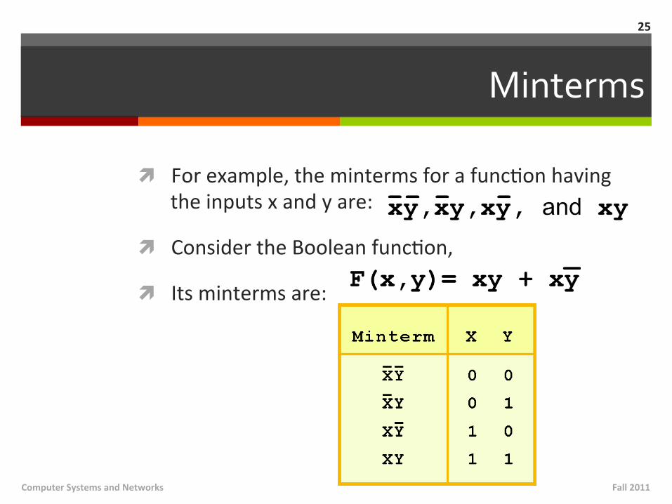
ì For example, the minterms for a funcMon having the inputs x and y are:
ì Consider the Boolean funcMon,
ì Its minterms are:
25
Fall 2011 Computer Systems and Networks
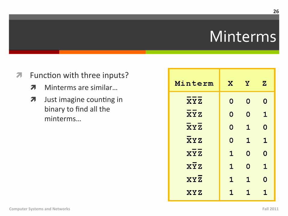
Minterms
ì FuncMon with three inputs? ì Minterms are similar… ì Just imagine counMng in
binary to find all the minterms…
Fall 2011 Computer Systems and Networks
26
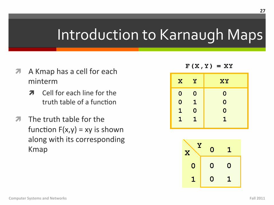
Introduction to Karnaugh Maps
ì A Kmap has a cell for each minterm ì Cell for each line for the
truth table of a funcMon
ì The truth table for the funcMon F(x,y) = xy is shown along with its corresponding Kmap
Fall 2011 Computer Systems and Networks
27
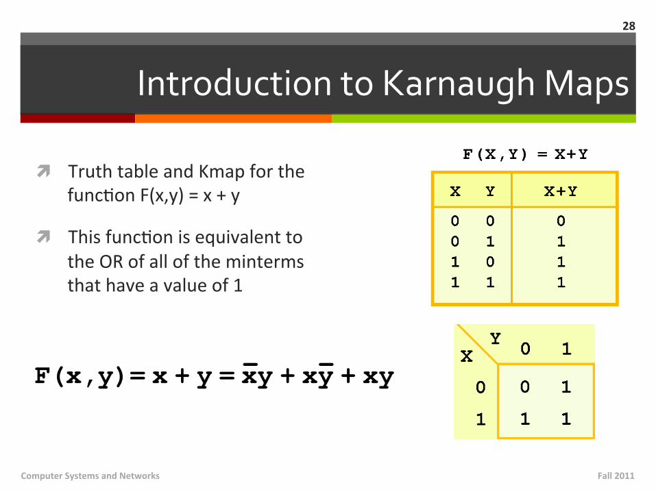
Introduction to Karnaugh Maps
ì Truth table and Kmap for the funcMon F(x,y) = x + y
ì This funcMon is equivalent to the OR of all of the minterms that have a value of 1
Fall 2011 Computer Systems and Networks
28
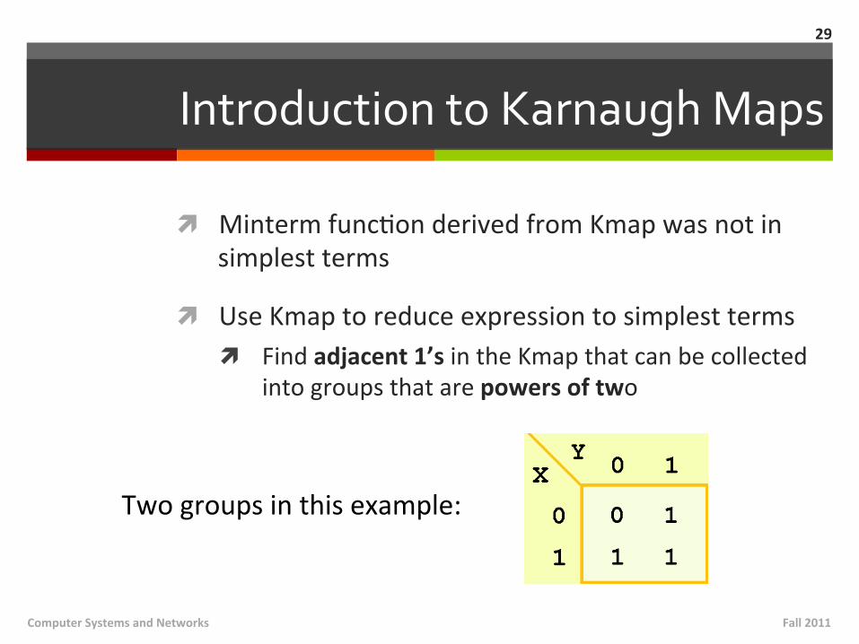
Introduction to Karnaugh Maps
ì Minterm funcMon derived from Kmap was not in simplest terms
ì Use Kmap to reduce expression to simplest terms ì Find adjacent 1’s in the Kmap that can be collected
into groups that are powers of two
29
Two groups in this example:
Fall 2011 Computer Systems and Networks
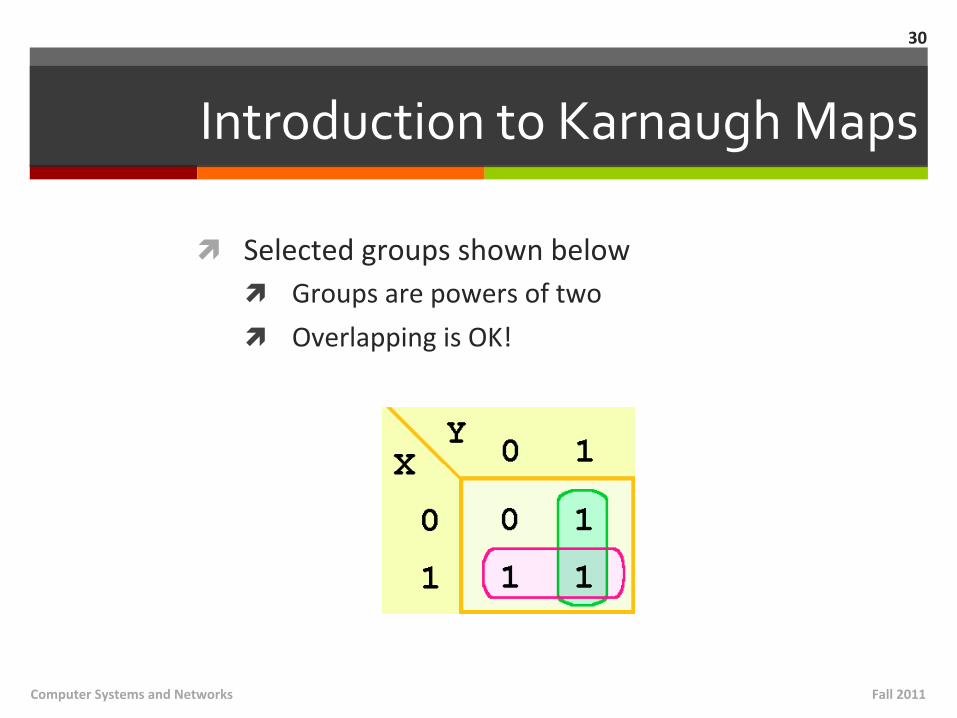
Introduction to Karnaugh Maps
ì Selected groups shown below ì Groups are powers of two ì Overlapping is OK!
30
Fall 2011 Computer Systems and Networks
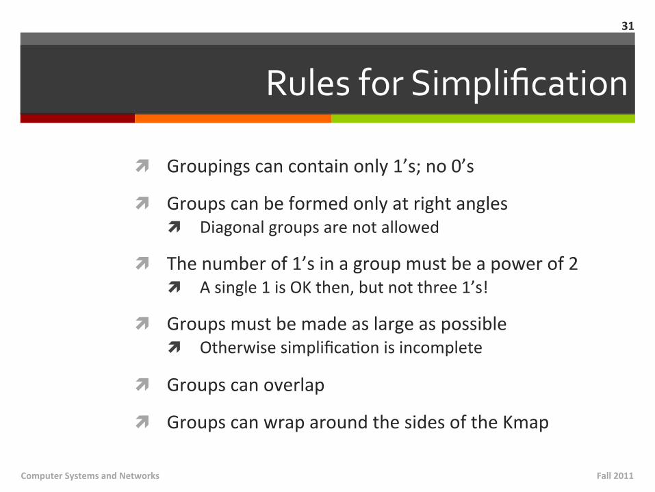
Rules for Simplification
ì Groupings can contain only 1’s; no 0’s
ì Groups can be formed only at right angles ì Diagonal groups are not allowed
ì The number of 1’s in a group must be a power of 2 ì A single 1 is OK then, but not three 1’s!
ì Groups must be made as large as possible ì Otherwise simplificaMon is incomplete
ì Groups can overlap
ì Groups can wrap around the sides of the Kmap
31
Fall 2011 Computer Systems and Networks

Kmap – Three Variables
ì Extend to three variables? Easy!
ì Note that the values for the yz combinaMon at the top of the matrix form a paiern that is not a normal binary sequence ì Each posiNon can only differ by 1 variable
32
Fall 2011 Computer Systems and Networks
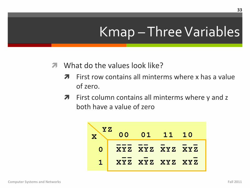
Kmap – Three Variables
ì What do the values look like? ì First row contains all minterms where x has a value
of zero. ì First column contains all minterms where y and z
both have a value of zero
33
Fall 2011 Computer Systems and Networks
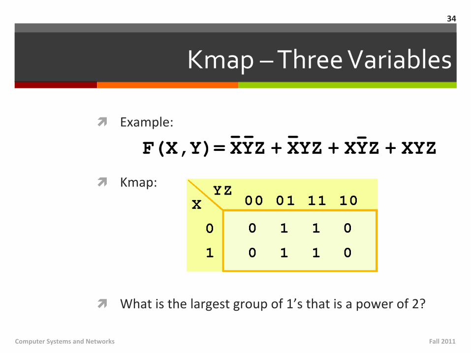
Kmap – Three Variables
ì Example:
ì Kmap:
ì What is the largest group of 1’s that is a power of 2?
34
Fall 2011 Computer Systems and Networks
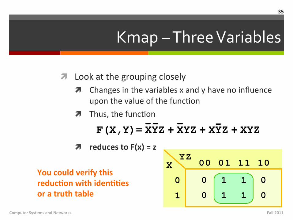
Kmap – Three Variables
ì Look at the grouping closely ì Changes in the variables x and y have no influence
upon the value of the funcMon ì Thus, the funcMon
ì reduces to F(x) = z
35
You could verify this reducNon with idenNNes or a truth table
Fall 2011 Computer Systems and Networks

Kmap – Three Variables
ì Example:
ì Kmap:
ì What are the largest groups of 1’s that are a power of 2? ì How many groups do you see?
36
Fall 2011 Computer Systems and Networks
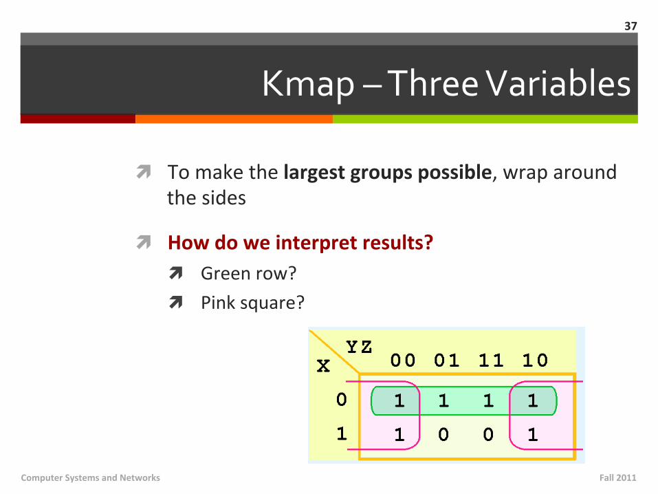
Kmap – Three Variables
ì To make the largest groups possible, wrap around the sides
ì How do we interpret results? ì Green row? ì Pink square?
37
Fall 2011 Computer Systems and Networks
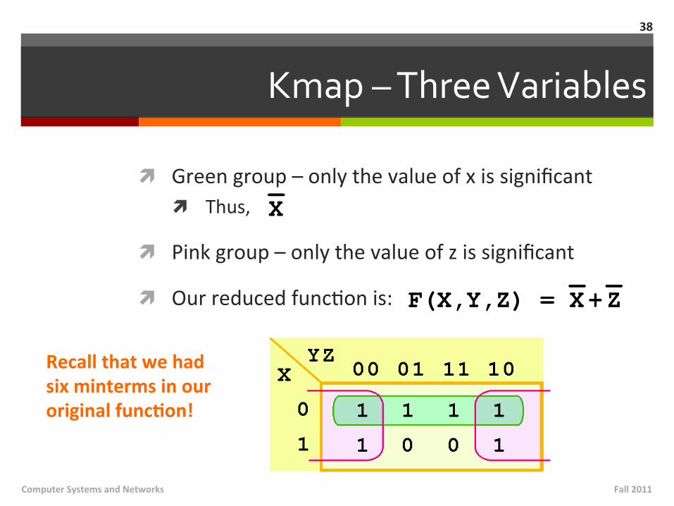
Kmap – Three Variables
ì Green group – only the value of x is significant ì Thus,
ì Pink group – only the value of z is significant
ì Our reduced funcMon is:
38
Recall that we had six minterms in our original funcNon!
Fall 2011 Computer Systems and Networks
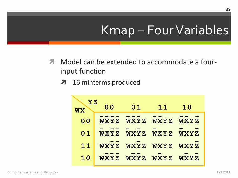
Kmap – Four Variables
ì Model can be extended to accommodate a four-‐input funcMon ì 16 minterms produced
39
Fall 2011 Computer Systems and Networks

Kmap – Four Variables
ì Example:
ì Kmap (showing non-‐zero terms)
ì What largest groups should we select? ì Groups can overlap! ì Groups can wrap!
Fall 2011 Computer Systems and Networks
40
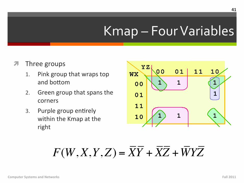
Kmap – Four Variables
ì Three groups 1. Pink group that wraps top
and boiom 2. Green group that spans the
corners 3. Purple group enMrely
within the Kmap at the right
Fall 2011 Computer Systems and Networks
41
F(W,X,Y,Z ) = XY + XZ +WYZ
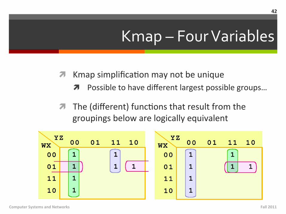
Kmap – Four Variables
ì Kmap simplificaMon may not be unique ì Possible to have different largest possible groups…
ì The (different) funcMons that result from the groupings below are logically equivalent
42
Fall 2011 Computer Systems and Networks
Don’t Care Conditions
ì Real circuits don’t always need to have an output defined for every possible input ì Example: Calculator displays have 7-‐segment LEDs.
These LEDs can display 27-‐1 paierns, but only ten of them are useful
ì If a circuit is designed so that a parMcular set of inputs can never happen, we call this set of inputs a don’t care condiMon ì Helpful for Kmap circuit simplificaMon
43
Fall 2011 Computer Systems and Networks
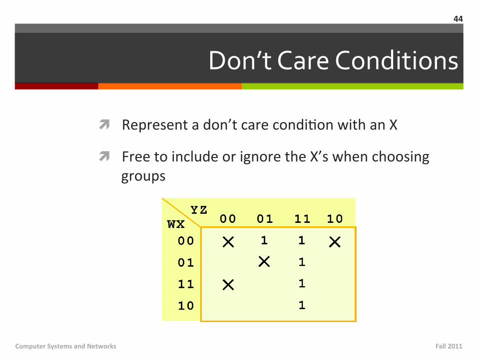
Don’t Care Conditions
ì Represent a don’t care condiMon with an X
ì Free to include or ignore the X’s when choosing groups
44
Fall 2011 Computer Systems and Networks
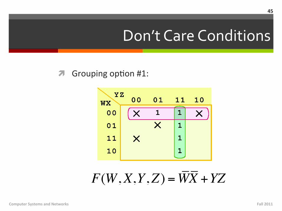
Don’t Care Conditions
ì Grouping opMon #1:
45
Fall 2011 Computer Systems and Networks
F(W,X,Y,Z ) =WX +YZ
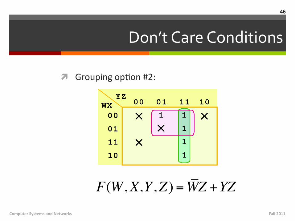
Don’t Care Conditions
ì Grouping opMon #2:
46
Fall 2011 Computer Systems and Networks
F(W,X,Y,Z ) =WZ +YZ
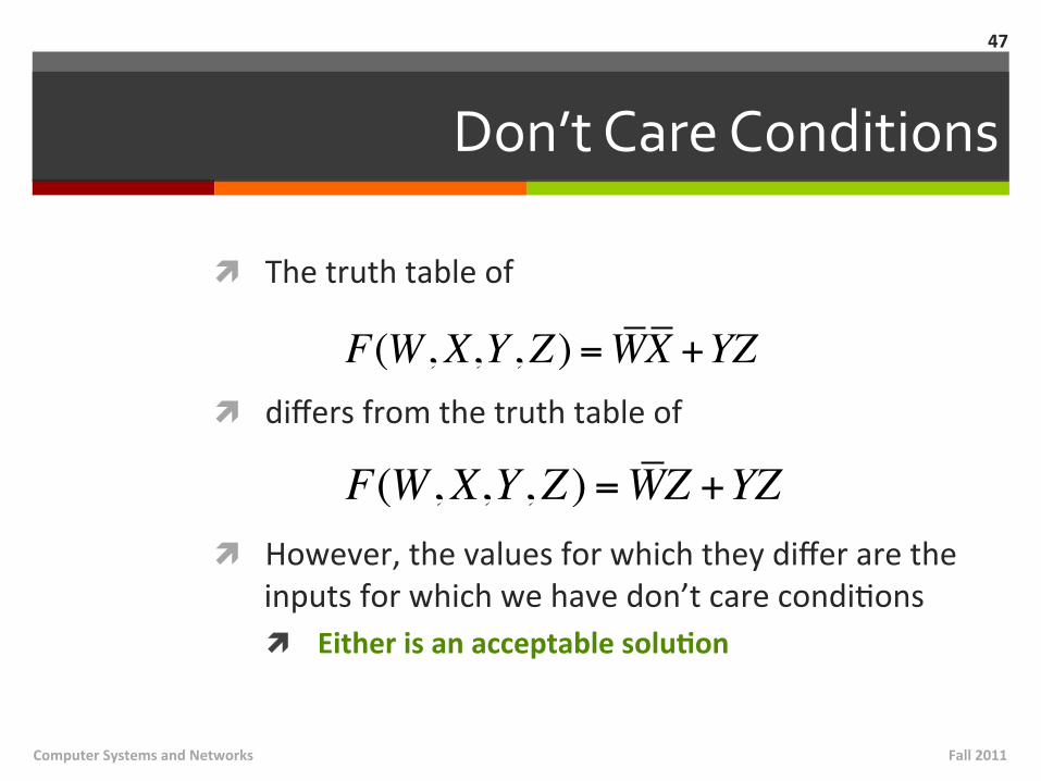
Don’t Care Conditions
ì The truth table of
ì differs from the truth table of
ì However, the values for which they differ are the inputs for which we have don’t care condiMons ì Either is an acceptable soluNon
47
Fall 2011 Computer Systems and Networks
F(W,X,Y,Z ) =WX +YZ
F(W,X,Y,Z ) =WZ +YZ

Homework #1 Review
ì Grades and soluNons posted on Sakai ì Papers available ager class (for those with Sakai issues…)
ì 50-‐word sentence -‐ Describe why the “Von Neumann bocleneck” constrains CPU performance ì The Von Neumann Bo2leneck is a constraint on stored
program machines in which the computer is limited to a single path between the main memory and the CPU, which forces the CPU to alternate between fetching and processing data, thereby limi@ng efficiency and performance. ì 44 words (< 50 word limit), 1 sentence
Fall 2011 Computer Systems and Networks
48
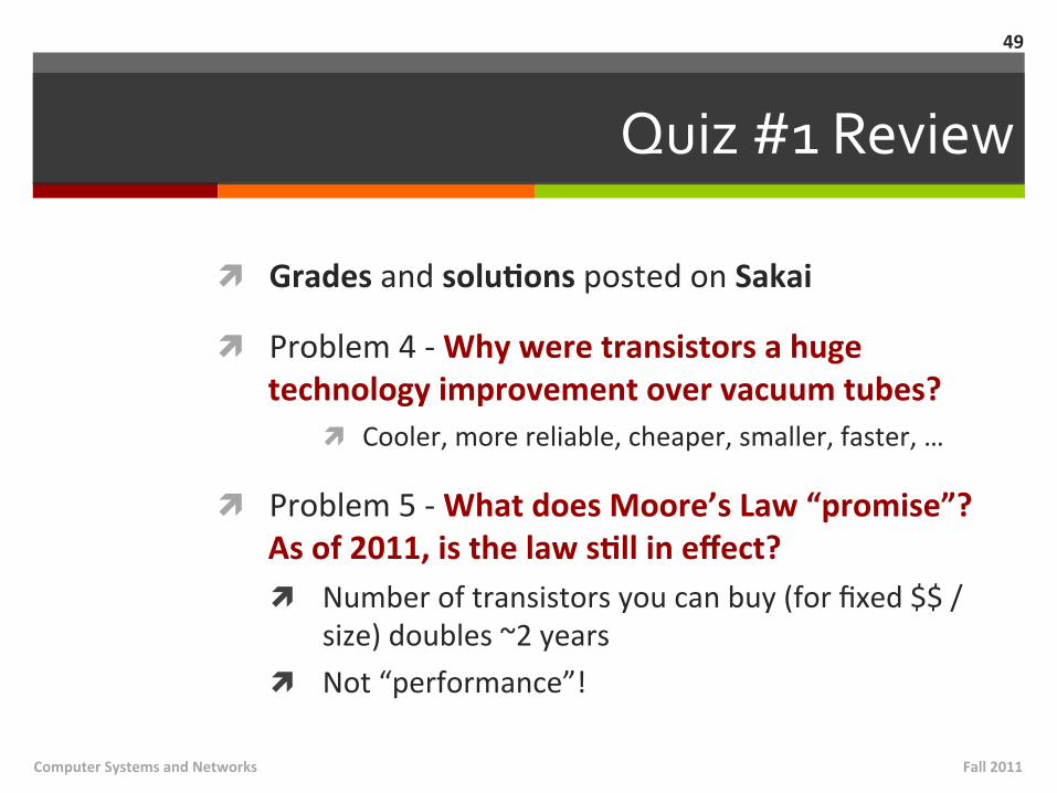
Quiz #1 Review
ì Grades and soluNons posted on Sakai
ì Problem 4 -‐ Why were transistors a huge technology improvement over vacuum tubes?
ì Cooler, more reliable, cheaper, smaller, faster, …
ì Problem 5 -‐ What does Moore’s Law “promise”? As of 2011, is the law sNll in effect? ì Number of transistors you can buy (for fixed $$ /
size) doubles ~2 years ì Not “performance”!
Fall 2011 Computer Systems and Networks
49

Quiz #1 Review
ì Problem 6 -‐ Memory is large and contains many instrucNons and data. How does the hardware know which instrucNon should be executed next? ì Program counter has next address in memory
ì Problem 6 -‐ What funcNon does the ALU perform? ì MathemaMcal operaMons! (Add, sub, mul, div,
compare, …)
Fall 2011 Computer Systems and Networks
50