STANAG 4529 CONFORMANCE TEST...
84
DEFENSE INFORMATION SYSTEMS AGENCY JOINT INTEROPERABILITY TEST COMMAND FORT HUACHUCA, ARIZONA STANAG 4529 CONFORMANCE TEST PROCEDURES APRIL 2004 Downloaded from http://www.everyspec.com
Transcript of STANAG 4529 CONFORMANCE TEST...

DEFENSE INFORMATION SYSTEMS AGENCY
JOINT INTEROPERABILITY TEST COMMAND
FORT HUACHUCA, ARIZONA
STANAG 4529
CONFORMANCE TEST PROCEDURES
APRIL 2004
Downloaded from http://www.everyspec.com

Downloaded from http://www.everyspec.com

Downloaded from http://www.everyspec.com

(This page intentionally left blank.)
Downloaded from http://www.everyspec.com

i
TABLE OF CONTENTS Page INTRODUCTION............................................................................................................. 1 TEST PROCEDURES..................................................................................................... 3 MODULATION RATES, DATA RATES, TIMING, AND SYNCHRONIZATION.............. 3
APPENDICES
ACRONYMS ............................................................................................................... A-1 STANAG 4529 REQUIREMENTS MATRIX................................................................ B-1 DATA COLLECTION FORMS .................................................................................... C-1 STANAG 4529 CONFORMANCE TEST PROCEDURES RESULTS MATRIX .......... D-1 REFERENCES.............................................................................................................E-1
LIST OF FIGURES
1.1 Phase State Encoding .......................................................................................... 4 1.2 Frame Structure.................................................................................................... 6 1.3 Synchronization Sequence Generator.................................................................. 7 1.4 Generation of Scrambling Sequence.................................................................... 8 1.5 Equipment Configuration for Data Analysis ........................................................ 10 1.6 Equipment Configuration for Output Power Measurements ............................... 11 1.7 Equipment Configuration for Clock Accuracy ..................................................... 11 1.8 Equipment Configuration for Frequency Error .................................................... 12
LIST OF TABLES
1.1 Symbol Number and Phase Conversion............................................................... 3 1.2 Bit Value and Symbol Linking for 600 bps Channel Rate ..................................... 4 1.3 Bit Value and Symbol Linking for 1200 bps Channel Rate ................................... 4 1.4 Bit Value and Symbol Linking for 1800 bps Channel Rate ................................... 5 1.5 Error Correction Coding........................................................................................ 9 1.6 Modulation Rates, Data Rates, Timing, and Synchronization Procedures ......... 13 1.7 Modulation Rates, Data Rates, Timing, and Synchronization Results................ 40 B-1 STANAG 4529 Requirements Matrix.................................................................B-3 D-1 STANAG 4529 Conformance Test Procedures Results Matrix......................... D-3
Downloaded from http://www.everyspec.com

ii
(This page intentionally left blank.)
Downloaded from http://www.everyspec.com
1
INTRODUCTION
The North Atlantic Treaty Organization Standardization Agreement (STANAG) 4529 establishes mandatory standards and design objectives that are necessary to ensure conformance for single-tone data modulators-demodulators (modems) for Maritime High Frequency (HF) radios, which establish links using 1240-Hertz (Hz) bandwidth signals. This document contains the test procedures that will be used to determine the level of compliance of single-tone data modems to the requirements of STANAG 4529. This test plan is intended to be generic and can be used to test any equipment that requires conformance to the STANAG 4529.
If test item performance does not meet a requirement, the failure and its potential operational impact will be discussed in the follow-on test report and/or certification letter. Any requirement capabilities that are not implemented will also be discussed.
The Joint Interoperability Test Command will conduct testing at Fort Huachuca, Arizona.
Downloaded from http://www.everyspec.com

2
(This page intentionally left blank.)
Downloaded from http://www.everyspec.com
3
TEST PROCEDURES MODULATION RATES, DATA RATES, TIMING, AND SYNCHRONIZATION 1.1 Objective. To determine the extent of compliance to the requirements of Standardization Agreement (STANAG) 4529, reference numbers 1-17. 1.2 Criteria
a. This document describes the modulation, call establishment process, and data correction required to ensure interoperability between modems transmitting data over High Frequency (HF) radio links where the data rate at the digital interface may be 75, 150, 300, 600, or 1200 bits per second (bps). The rate at which data (user data bits plus bits for error correction coding) is transmitted (i.e., the channel data rate) may be a 600 bps (when the user data rate is 75, 150, or 300 bps), 1200 bps (when the user data rate is 600 bps), or 1800 bps (when the user data rate is 1200 bps). The equipment may also be used for uncoded data transmission in which data input to a modulator’s digital interface is transmitted without the addition of the error correction coding and interleaving described in paragraph 10. The uncoded modes provide data rates of 600, 1200, and 1800 bps. (appendix B, reference numbers 1 and 2)
b. The modulation technique consists of phase shifting of a subcarrier
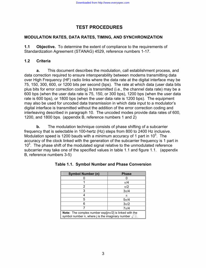
frequency that is selectable in 100-hertz (Hz) steps from 800 to 2400 Hz inclusive. Modulation speed is 1200 bauds with a minimum accuracy of 1 part in 105. The accuracy of the clock linked with the generation of the subcarrier frequency is 1 part in 105. The phase shift of the modulated signal relative to the unmodulated reference subcarrier may take one of the specified values in table 1.1 and figure 1.1. (appendix B, reference numbers 3-5)
Table 1.1. Symbol Number and Phase Conversion
Symbol Number (n) Phase
0 0 1 π/4 2 π/2 3 3π/4 4 π 5 5π/4 6 3π/2 7 7π/4
Note: The complex number exp[jnπ/2] is linked with the symbol number n, where j is the imaginary number 1− .
Downloaded from http://www.everyspec.com

4
Symbol 2
Symbol 1
Symbol 0
Symbol 7
Symbol 6
Symbol 5
Symbol 4
Symbol 3
Figure 1.1. Phase State Encoding
c. For the 600 bps channel data rate (75, 150, and 300 bps user data rates), transcoding is achieved by linking one symbol to one bit according to table 1.2. For the 1200 bps channels data rate (600 bps user data rate), transcoding is achieved by linking one symbol to a set of two consecutive bits (dibit) according to table 1.3. For the 1800 bps channel data rate (1200 bps user data rate), transcoding is achieved by linking one symbol to a set of three consecutive bits (tribit) according to table 1.4. (appendix B, reference numbers 6-8)
Table 1.2. Bit Value and Symbol Linking for 600 bps Channel Rate
Bit Symbol 0 0 1 4
Table 1.3. Bit Value and Symbol Linking for 1200 bps Channel Rate
Dibit Symbol
00 0 01 2 11 4 10 6
↑ Most recent bit
Downloaded from http://www.everyspec.com

5
Table 1.4. Bit Value and Symbol Linking for 1800 bps Channel Rate
Tribit Symbol 000 1 001 0 010 2 011 3 100 6 101 7 110 5 111 4
↑ Most recent bit
d. The power spectral density of the modulated signal shall be centered on a
frequency that is selectable in 100 Hz to 2400 Hz inclusive, with a default value of 1700 Hz. Filtering shall be applied as necessary so that 99 percent (%) of the output power is within 1240 Hz. (appendix B, reference numbers 9-10)
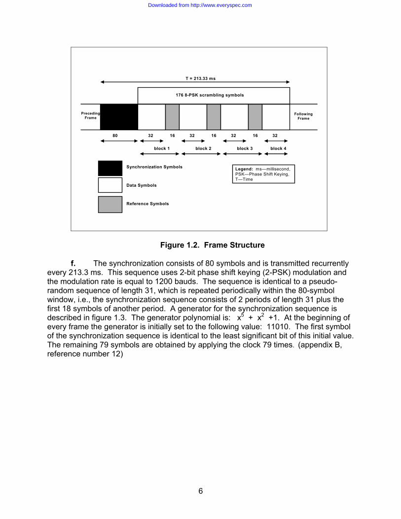
e. The symbols to be transmitted are structured in recurrent frames 213.3
milliseconds (ms) in length as shown in figure 1.2. A frame consists of 256 symbols. A frame can be broken down into: 80 symbols for synchronization, 48 reference symbols, and 128 data symbols. The 176 reference and data symbols are scrambled by a scrambling sequence with eight-phase-states of length 176. The reference and data symbols are formed into 4 blocks: the first 3 consist of 32 data symbols followed by 16 reference symbols; the last block consists of 32 symbols. The reference symbols are all symbol number 0. (appendix B, reference number 11)
Downloaded from http://www.everyspec.com
6
176 8-PSK scrambling symbols
32 32 32 3216 16 1680
block 1 block 2 block 3 block 4
T = 213.33 ms
PrecedingFrame
FollowingFrame
Synchronization Symbols
Data Symbols
Reference Symbols
Legend: ms—millisecond, PSK—Phase Shift Keying,T—Time
Figure 1.2. Frame Structure f. The synchronization consists of 80 symbols and is transmitted recurrently
every 213.3 ms. This sequence uses 2-bit phase shift keying (2-PSK) modulation and the modulation rate is equal to 1200 bauds. The sequence is identical to a pseudo-random sequence of length 31, which is repeated periodically within the 80-symbol window, i.e., the synchronization sequence consists of 2 periods of length 31 plus the first 18 symbols of another period. A generator for the synchronization sequence is described in figure 1.3. The generator polynomial is: x5 + x2 +1. At the beginning of every frame the generator is initially set to the following value: 11010. The first symbol of the synchronization sequence is identical to the least significant bit of this initial value. The remaining 79 symbols are obtained by applying the clock 79 times. (appendix B, reference number 12)
Downloaded from http://www.everyspec.com

7
1 1 0 1 0
X4 X3 X2 X1 X0
+
Initialization Values
Synchronization Sequence Output
Figure 1.3. Synchronization Sequence Generator
g. The scrambling sequence is composed of 176 symbols and is repeated every 213.3 ms. This sequence is transmitted in eight-phase-state modulation at the rate of 1200 bauds. Data scrambling by an eight-phase-state sequence is done to maintain commonality with STANAG 4285 implementations. The scrambling symbol generator is shown in figure 1.4. The symbols are formed by means of a pseudo-random code of length 511, the generator polynomial of which is: x9 + x4 + 1. The generator is initialized to 1 at the start of each frame. A symbol is derived from the triplet consisting of the last three bits in the Pseudo-random Numerical (PN) register, i.e., x0 x1 x2 by the following relationship:
Scrambling symbol Bk = exp[jnπ/4] Where: n = 4x2 + 2x1 + x0
x0 = 0 or 1 x1 = 0 or 1 x2 = 0 or 1 Generation from one symbol to the next is by successive shifting of the PN register by three positions. (appendix B, reference number 13)
Downloaded from http://www.everyspec.com

8
Initialization Values
Scrambling Symbols
+
1 1 1 1 1 1 1 1 1 1
X9 X8 X7 X6 X5 X4 X3 X2 X1 X0
Transcoding
Figure 1.4. Generation of Scrambling Sequence
h. The scrambling operation is carried out on reference and data symbols only, not on the synchronization sequence. This operation consists of module 8 addition of the data symbol number to the scrambling symbol number; this amounts to complex multiplication of the data symbol by the scrambling symbol. (appendix B, reference number 14) i. The modem must be capable of tolerating a frequency error of +/-37.5 Hz between the transmission and reception of HF carriers (transmitter/receiver frequency error and Doppler shift included) and rate of frequency change of up to 3.5 Hz/second (sec). (appendix B, reference number 15)
j. For the error correction modes defined in this STANAG, the error correction coding used shall be the rate ½, constraint length 7 convolutional coding as described STANAG 4285, annex E. For each user data rate described in this STANAG (i.e., 75, 150, 300, 600, and 1200 bps) the coding, interleaving, and flush bits shall be as described for the higher data rate in STANAG 4285, annex E. The changes necessary to allow 1240-Hz operation are explicitly shown, in table 1.5. The error correction coding used shall be as in STANAG 4285, annex E, section 2 with the following changes as shown in table 1.5.
Downloaded from http://www.everyspec.com

9
Table 1.5. Error Correction Coding Coded data area Waveform Effective code rate Coding method
1200 bps 8 phase (1800 bps) 2/3 Rate 1/2 punctured to rate 2/3 600 bps 4 phase (1200 bps) 1/2 Rate 1/2 code 300 bps 2 phase (600 bps) 1/2 Rate 1/2 code 150 bps 2 phase (600 bps) 1/4 Rate 1/2 code repeated 2x 75 bps 2 phase (600 bps) 1/8 Rate 1/2 code repeated 4x
Legend: bps—bits per second
The interleaving shall be as described in STANAG 4285, annex E, section 3 with the following different parameters: Number of rows: I = 32 for all data rates Delay increment “j” for each successive row: Total Interleaving Delay: Data rates 20.48 sec 1.706 sec 1200 bps 48 4 600 bps 24 2 300, 150 and 75 bps 12 1 Interleaver synchronization shall be as described in STANAG 4285, annex E, part 4 with no changes. The initialization and message protocol for use with coding and interleaving shall be as described in STANAG 4285, annex E, part 5 with the following difference:
The number of flush zeros for each of the data rates and the two interleaver lengths are as follows: (appendix B, reference number 16) Interleaver Delay Data rate 20.48 sec 1.706 sec 1200 bps 24678 2150 600 bps 12390 1126 300 bps 6246 614 150 bps 3174 358 75 bps 1638 230
k. Modems shall provide uncoded data transmission modes, in which the coding, interleaving, and associated initialization and message protocols (described in section 10 of STANAG 4529) are not applied to the data transmitted. Uncoded data modes shall retain all other characteristics described in STANAG 4529, annex A, paragraph 11. Uncoded data rates of 600, 1200, and 1800 bps shall be provided. (appendix B, reference number 17)
Downloaded from http://www.everyspec.com
10
1.3 Test Procedures
a. Test Equipment Required
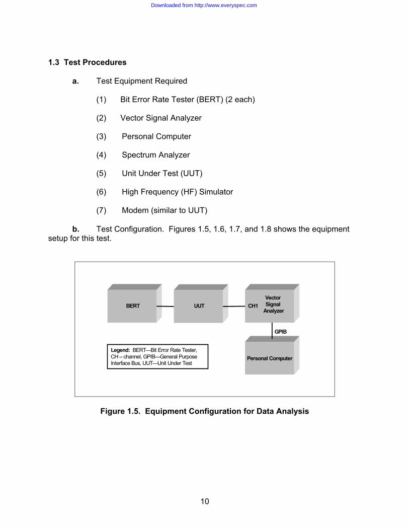
(1) Bit Error Rate Tester (BERT) (2 each) (2) Vector Signal Analyzer (3) Personal Computer (4) Spectrum Analyzer (5) Unit Under Test (UUT) (6) High Frequency (HF) Simulator (7) Modem (similar to UUT)
b. Test Configuration. Figures 1.5, 1.6, 1.7, and 1.8 shows the equipment setup for this test.
BERT UUTVectorSignal
AnalyzerCH1
Legend: BERT—Bit Error Rate Tester, CH – channel, GPIB—General Purpose Interface Bus, UUT—Unit Under Test
Personal Computer
GPIB
Figure 1.5. Equipment Configuration for Data Analysis
Downloaded from http://www.everyspec.com

11
BERT UUT SpectrumAnalyzer
CH1
Legend: BERT—Bit Error Rate Tester, CH –channel, UUT—Unit Under Test
Figure 1.6. Equipment Configuration for Output Power Measurements
UUT
Legend: BERT—Bit Error Rate Tester, UUT—Unit Under Test
BERT
Figure 1.7. Equipment Configuration for Clock Accuracy
Downloaded from http://www.everyspec.com
12
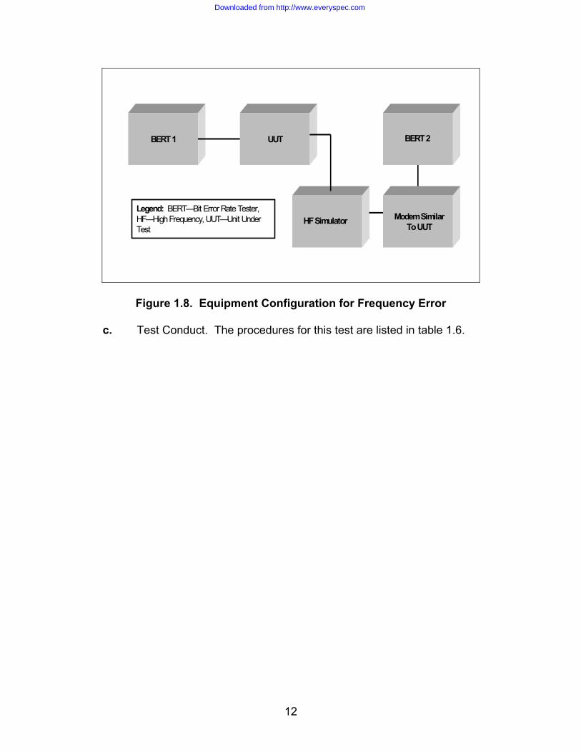
BERT 1 UUT
Legend: BERT—Bit Error Rate Tester, HF—High Frequency, UUT—Unit Under Test
Modem SimilarTo UUT
HF Simulator
BERT 2
Figure 1.8. Equipment Configuration for Frequency Error c. Test Conduct. The procedures for this test are listed in table 1.6.
Downloaded from http://www.everyspec.com

13
Table 1.6. Modulation Rates, Data Rates, Timing, and Synchronization Procedures
Step Action Settings/Action Result
The following procedures are for reference numbers 1, 2, and 12.
1
Set up equipment. Set up equipment as shown in figure 1.5. Configure the vector analyzer so its phase state diagram is as specified in figure 1.1 and tables 1.2, 1.3, and 1.4.
2
Configure vector signal analyzer. Frequency Center: 2 kHz Span: 1.24 kHz Time Result Length: 2000 symbols Search Length: 853.33 ms Sync Setup
Pattern: 01011001111100011011 Offset: 0 symbols
Instrument Mode Digital Demodulation Demodulation Setup Demodulation Format: BPSK Symbol Rate: 1.2 kHz Result Length: 1000 symbols Reference Filter: Raised Cos Meas Filter: Root Raised Cos Alpha: 0.16 Sweep: Single Trigger Trigger Type: IF CH1 Configure state constellation diagram as given in figure 1.1.
3
Configure UUT. Configure the UUT to transmit using a STANAG 4529 coded, 75 bps, short interleaving waveform. Configure the subcarier frequency to 2000 Hz.
4
Configure BERT. Configure the BERT to transmit: “THE QUICK BROWN FOX JUMPS OVER THE LAZY DOG 0123456789” using 7-bit ASCII.
5
Transmit data. Allow for the BERT to transmit its data through the UUT. Save the data captured on the vector signal analyzer to a file.
Downloaded from http://www.everyspec.com

14
Table 1.6. Modulation Rates, Data Rates, Timing, and Synchronization Procedures (continued)
Step Action Settings/Action Result
6
Verify vector signal analyzer was able to synchronize.
On the vector signal analyzer screen, compare the following BPSK synchronization sequence pattern to the pattern that the vector signal analyzer synchronized on: 0 1 0 1 1 0 0 1 1 1 1 1 0 0 0 1 1 0 1 1 1 0 1 0 1 0 0 0 0 1 0 0 1 0 1 1 0 0 1 1 1 1 1 0 0 0 1 1 0 1 1 1 0 1 0 1 0 0 0 0 1 0 0 1 0 1 1 0 0 1 1 1 1 1 0 0 0 1 1 0
7 Re-configure UUT. Re-configure the UUT to transmit with coded, 75 bps, long interleaving.
8
Configure BERT. Configure the BERT to transmit: “THE QUICK BROWN FOX JUMPS OVER THE LAZY DOG 0123456789” using 7-bit ASCII.
9
Transmit data. Allow for the BERT to transmit its data through the UUT. Save the data captured on the vector signal analyzer to a file.
10
Verify vector signal analyzer was able to synchronize.
On the vector signal analyzer screen, compare the following BPSK synchronization sequence pattern to the pattern that the vector signal analyzer synchronized on: 0 1 0 1 1 0 0 1 1 1 1 1 0 0 0 1 1 0 1 1 1 0 1 0 1 0 0 0 0 1 0 0 1 0 1 1 0 0 1 1 1 1 1 0 0 0 1 1 0 1 1 1 0 1 0 1 0 0 0 0 1 0 0 1 0 1 1 0 0 1 1 1 1 1 0 0 0 1 1 0
11 Re-configure UUT. Re-configure the UUT to transmit with coded, 150 bps, short interleaving.
12
Configure BERT. Configure the BERT to transmit: “THE QUICK BROWN FOX JUMPS OVER THE LAZY DOG 0123456789” using 7-bit ASCII.
13
Transmit data. Allow for the BERT to transmit its data through the UUT. Save the data captured on the vector signal analyzer to a file.
Downloaded from http://www.everyspec.com

15
Table 1.6. Modulation Rates, Data Rates, Timing, and Synchronization Procedures (continued)
Step Action Settings/Action Result
14
Verify vector signal analyzer was able to synchronize.
On the vector signal analyzer screen, compare the following BPSK synchronization sequence pattern to the pattern that the vector signal analyzer synchronized on: 0 1 0 1 1 0 0 1 1 1 1 1 0 0 0 1 1 0 1 1 1 0 1 0 1 0 0 0 0 1 0 0 1 0 1 1 0 0 1 1 1 1 1 0 0 0 1 1 0 1 1 1 0 1 0 1 0 0 0 0 1 0 0 1 0 1 1 0 0 1 1 1 1 1 0 0 0 1 1 0
15 Re-configure UUT. Re-configure the UUT to transmit with coded, 150 bps, long interleaving.
16
Configure BERT. Configure the BERT to transmit: “THE QUICK BROWN FOX JUMPS OVER THE LAZY DOG 0123456789” using 7-bit ASCII.
17
Transmit data. Allow for the BERT to transmit its data through the UUT. Save the data captured on the vector signal analyzer to a file.
18
Verify vector signal analyzer was able to synchronize.
On the vector signal analyzer screen, compare the following BPSK synchronization sequence pattern to the pattern that the vector signal analyzer synchronized on: 0 1 0 1 1 0 0 1 1 1 1 1 0 0 0 1 1 0 1 1 1 0 1 0 1 0 0 0 0 1 0 0 1 0 1 1 0 0 1 1 1 1 1 0 0 0 1 1 0 1 1 1 0 1 0 1 0 0 0 0 1 0 0 1 0 1 1 0 0 1 1 1 1 1 0 0 0 1 1 0
19 Re-configure UUT. Re-configure the UUT to transmit with coded, 300 bps, short interleaving.
20
Configure BERT. Configure the BERT to transmit: “THE QUICK BROWN FOX JUMPS OVER THE LAZY DOG 0123456789” using 7-bit ASCII.
21
Transmit data. Allow for the BERT to transmit its data through the UUT. Save the data captured on the vector signal analyzer to a file.
Downloaded from http://www.everyspec.com

16
Table 1.6. Modulation Rates, Data Rates, Timing, and Synchronization Procedures (continued)
Step Action Settings/Action Result
22
Verify vector signal analyzer was able to synchronize.
On the vector signal analyzer screen, compare the following BPSK synchronization sequence pattern to the pattern that the vector signal analyzer synchronized on: 0 1 0 1 1 0 0 1 1 1 1 1 0 0 0 1 1 0 1 1 1 0 1 0 1 0 0 0 0 1 0 0 1 0 1 1 0 0 1 1 1 1 1 0 0 0 1 1 0 1 1 1 0 1 0 1 0 0 0 0 1 0 0 1 0 1 1 0 0 1 1 1 1 1 0 0 0 1 1 0
23 Re-configure UUT. Re-configure the UUT to transmit with coded, 300 bps, long interleaving.
24
Configure BERT. Configure the BERT to transmit: “THE QUICK BROWN FOX JUMPS OVER THE LAZY DOG 0123456789” using 7-bit ASCII.
25
Transmit data. Allow for the BERT to transmit its data through the UUT. Save the data captured on the vector signal analyzer to a file.
26
Verify vector signal analyzer was able to synchronize.
On the vector signal analyzer screen, compare the following BPSK synchronization sequence pattern to the pattern that the vector signal analyzer synchronized on: 0 1 0 1 1 0 0 1 1 1 1 1 0 0 0 1 1 0 1 1 1 0 1 0 1 0 0 0 0 1 0 0 1 0 1 1 0 0 1 1 1 1 1 0 0 0 1 1 0 1 1 1 0 1 0 1 0 0 0 0 1 0 0 1 0 1 1 0 0 1 1 1 1 1 0 0 0 1 1 0
27 Re-configure UUT. Re-configure the UUT to transmit with coded, 600 bps, short interleaving.
28
Configure BERT. Configure the BERT to transmit: “THE QUICK BROWN FOX JUMPS OVER THE LAZY DOG 0123456789” using 7-bit ASCII.
29
Transmit data. Allow for the BERT to transmit its data through the UUT. Save the data captured on the vector signal analyzer to a file.
Downloaded from http://www.everyspec.com
17
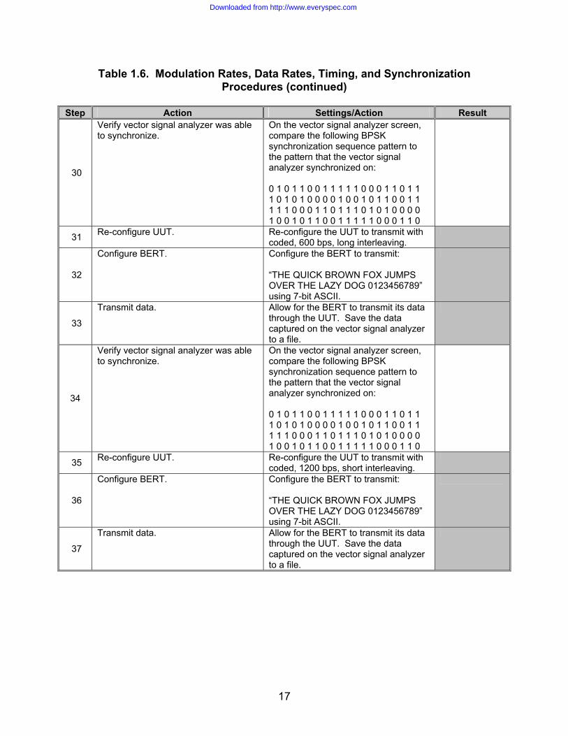
Table 1.6. Modulation Rates, Data Rates, Timing, and Synchronization Procedures (continued)
Step Action Settings/Action Result
30
Verify vector signal analyzer was able to synchronize.
On the vector signal analyzer screen, compare the following BPSK synchronization sequence pattern to the pattern that the vector signal analyzer synchronized on: 0 1 0 1 1 0 0 1 1 1 1 1 0 0 0 1 1 0 1 1 1 0 1 0 1 0 0 0 0 1 0 0 1 0 1 1 0 0 1 1 1 1 1 0 0 0 1 1 0 1 1 1 0 1 0 1 0 0 0 0 1 0 0 1 0 1 1 0 0 1 1 1 1 1 0 0 0 1 1 0
31 Re-configure UUT. Re-configure the UUT to transmit with coded, 600 bps, long interleaving.
32
Configure BERT. Configure the BERT to transmit: “THE QUICK BROWN FOX JUMPS OVER THE LAZY DOG 0123456789” using 7-bit ASCII.
33
Transmit data. Allow for the BERT to transmit its data through the UUT. Save the data captured on the vector signal analyzer to a file.
34
Verify vector signal analyzer was able to synchronize.
On the vector signal analyzer screen, compare the following BPSK synchronization sequence pattern to the pattern that the vector signal analyzer synchronized on: 0 1 0 1 1 0 0 1 1 1 1 1 0 0 0 1 1 0 1 1 1 0 1 0 1 0 0 0 0 1 0 0 1 0 1 1 0 0 1 1 1 1 1 0 0 0 1 1 0 1 1 1 0 1 0 1 0 0 0 0 1 0 0 1 0 1 1 0 0 1 1 1 1 1 0 0 0 1 1 0
35 Re-configure UUT. Re-configure the UUT to transmit with coded, 1200 bps, short interleaving.
36
Configure BERT. Configure the BERT to transmit: “THE QUICK BROWN FOX JUMPS OVER THE LAZY DOG 0123456789” using 7-bit ASCII.
37
Transmit data. Allow for the BERT to transmit its data through the UUT. Save the data captured on the vector signal analyzer to a file.
Downloaded from http://www.everyspec.com
18
Table 1.6. Modulation Rates, Data Rates, Timing, and Synchronization Procedures (continued)
Step Action Settings/Action Result
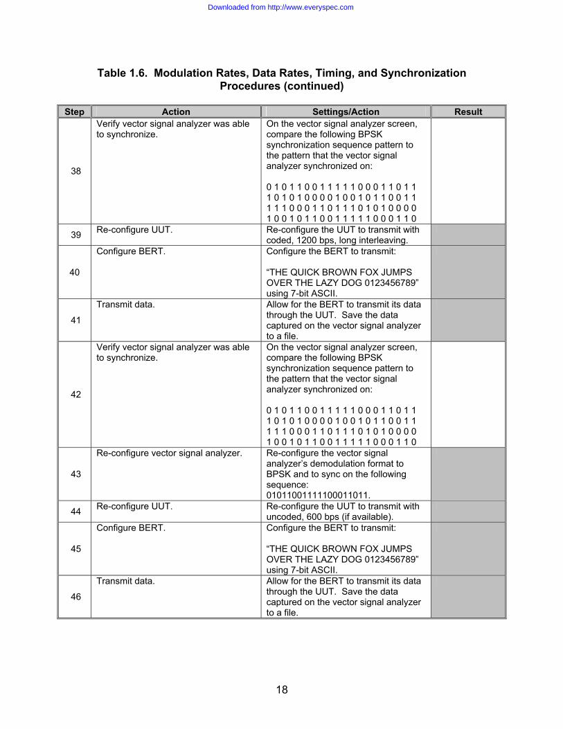
38
Verify vector signal analyzer was able to synchronize.
On the vector signal analyzer screen, compare the following BPSK synchronization sequence pattern to the pattern that the vector signal analyzer synchronized on: 0 1 0 1 1 0 0 1 1 1 1 1 0 0 0 1 1 0 1 1 1 0 1 0 1 0 0 0 0 1 0 0 1 0 1 1 0 0 1 1 1 1 1 0 0 0 1 1 0 1 1 1 0 1 0 1 0 0 0 0 1 0 0 1 0 1 1 0 0 1 1 1 1 1 0 0 0 1 1 0
39 Re-configure UUT. Re-configure the UUT to transmit with coded, 1200 bps, long interleaving.
40
Configure BERT. Configure the BERT to transmit: “THE QUICK BROWN FOX JUMPS OVER THE LAZY DOG 0123456789” using 7-bit ASCII.
41
Transmit data. Allow for the BERT to transmit its data through the UUT. Save the data captured on the vector signal analyzer to a file.
42
Verify vector signal analyzer was able to synchronize.
On the vector signal analyzer screen, compare the following BPSK synchronization sequence pattern to the pattern that the vector signal analyzer synchronized on: 0 1 0 1 1 0 0 1 1 1 1 1 0 0 0 1 1 0 1 1 1 0 1 0 1 0 0 0 0 1 0 0 1 0 1 1 0 0 1 1 1 1 1 0 0 0 1 1 0 1 1 1 0 1 0 1 0 0 0 0 1 0 0 1 0 1 1 0 0 1 1 1 1 1 0 0 0 1 1 0
43
Re-configure vector signal analyzer. Re-configure the vector signal analyzer’s demodulation format to BPSK and to sync on the following sequence: 01011001111100011011.
44 Re-configure UUT. Re-configure the UUT to transmit with uncoded, 600 bps (if available).
45
Configure BERT. Configure the BERT to transmit: “THE QUICK BROWN FOX JUMPS OVER THE LAZY DOG 0123456789” using 7-bit ASCII.
46
Transmit data. Allow for the BERT to transmit its data through the UUT. Save the data captured on the vector signal analyzer to a file.
Downloaded from http://www.everyspec.com

19
Table 1.6. Modulation Rates, Data Rates, Timing, and Synchronization Procedures (continued)
Step Action Settings/Action Result
47
Verify vector signal analyzer was able to synchronize.
On the vector signal analyzer screen, compare the following BPSK synchronization sequence pattern to the pattern that the vector signal analyzer synchronized on: 0 1 0 1 1 0 0 1 1 1 1 1 0 0 0 1 1 0 1 1 1 0 1 0 1 0 0 0 0 1 0 0 1 0 1 1 0 0 1 1 1 1 1 0 0 0 1 1 0 1 1 1 0 1 0 1 0 0 0 0 1 0 0 1 0 1 1 0 0 1 1 1 1 1 0 0 0 1 1 0
48 Re-configure UUT. Re-configure the UUT to transmit with uncoded, 1200 bps (if available).
49
Configure BERT. Configure the BERT to transmit: “THE QUICK BROWN FOX JUMPS OVER THE LAZY DOG 0123456789” using 7-bit ASCII.
50
Transmit data. Allow for the BERT to transmit its data through the UUT. Save the data captured on the vector signal analyzer to a file.
51
Verify vector signal analyzer was able to synchronize.
On the vector signal analyzer screen, compare the following BPSK synchronization sequence pattern to the pattern that the vector signal analyzer synchronized on: 0 1 0 1 1 0 0 1 1 1 1 1 0 0 0 1 1 0 1 1 1 0 1 0 1 0 0 0 0 1 0 0 1 0 1 1 0 0 1 1 1 1 1 0 0 0 1 1 0 1 1 1 0 1 0 1 0 0 0 0 1 0 0 1 0 1 1 0 0 1 1 1 1 1 0 0 0 1 1 0
52 Re-configure UUT. Re-configure the UUT to transmit with uncoded, 1800 bps (if available).
53
Configure BERT. Configure the BERT to transmit: “THE QUICK BROWN FOX JUMPS OVER THE LAZY DOG 0123456789” using 7-bit ASCII.
54
Transmit data. Allow for the BERT to transmit its data through the UUT. Save the data captured on the vector signal analyzer to a file.
Downloaded from http://www.everyspec.com

20
Table 1.6. Modulation Rates, Data Rates, Timing, and Synchronization Procedures (continued)
Step Action Settings/Action Result
55
Verify vector signal analyzer was able to synchronize.
On the vector signal analyzer screen, compare the following BPSK synchronization sequence pattern to the pattern that the vector signal analyzer synchronized on: 0 1 0 1 1 0 0 1 1 1 1 1 0 0 0 1 1 0 1 1 1 0 1 0 1 0 0 0 0 1 0 0 1 0 1 1 0 0 1 1 1 1 1 0 0 0 1 1 0 1 1 1 0 1 0 1 0 0 0 0 1 0 0 1 0 1 1 0 0 1 1 1 1 1 0 0 0 1 1 0
The following procedures are for reference numbers 5-8, 11, 13-14, and 16.
56
The following procedures use automated software to decode STANAG 4529 data transmitted from the UUT. The test operator must program the UUT to transmit the following test pattern: “THE QUICK BROWN FOX JUMPS OVER THE LAZY DOG 0123456789” using 7-bit ASCII. The automated software is available for download from the JITC website: http://jitc.fhu.disa.mil/it/hf.htm
Successful decode of the STANAG 4529 data validates that the following requirements have been met: FEC encoder, interleaver, frame synchronization symbols, scrambler, reference symbols, frame structure, and transcoding.
57 Copy and paste STANAG4529.vi file onto hard disk of personal computer containing LabVIEW software.
Copy and paste 4529.STA file onto a 3.5-inch floppy disk. Insert floppy disk into drive a: of vector signal analyzer.
58 Connect the UUT to channel 1 of the vector signal analyzer.
Connect the vector signal analyzer to personal computer via the GPIB interface.
59 Load LabVIEW software. Open STANAG4529.vi.
60
Program the UUT to send STANAG 4529 data at coded 75 bps, using the short interleaver and a subcarrier frequency of 2000 Hz.
Ensure that the UUT is in the idle state (not sending).
61 Use the automated software’s Test Information box to select data rate, interleaver, and uncoded/coded type.
62
Run STANAG4529.vi file. Observe vector signal analyzer. When analyzer displays “Waiting for Trigger,” key the modem and begin sending test pattern stated in step 56.
Downloaded from http://www.everyspec.com

21
Table 1.6. Modulation Rates, Data Rates, Timing, and Synchronization Procedures (continued)
Step Action Settings/Action Result
63
Automated software will run for several minutes.
Record results of software decode. (Note that the operator may choose to view the raw data captured on the vector signal analyzer). Save encoded data to file.
64
Program the UUT to send STANAG 4529 data at coded 75 bps, using the long interleaver and a subcarrier frequency of 2000 Hz.
Ensure that the UUT is in the idle state (not sending).
65 Use the automated software’s Test Information box to select data rate, interleaver, and uncoded/coded type.
66
Run STANAG4529.vi file. Observe vector signal analyzer. When analyzer displays “Waiting for Trigger,” key the modem and begin sending test pattern stated in step 56.
67
Automated software will run for several minutes.
Record results of software decode. (Note that the operator may choose to view the raw data captured on the vector signal analyzer). Save encoded data to file.
68
Program the UUT to send STANAG 4529 data at coded 150 bps, using the short interleaver and a subcarrier frequency of 2000 Hz.
Ensure that the UUT is in the idle state (not sending).
69 Use the automated software’s Test Information box to select data rate, interleaver, and uncoded/coded type.
70
Run STANAG4529.vi file. Observe vector signal analyzer. When analyzer displays “Waiting for Trigger,” key the modem and begin sending test pattern stated in step 56.
71
Automated software will run for several minutes.
Record results of software decode. (Note that the operator may choose to view the raw data captured on the vector signal analyzer). Save encoded data to file.
72
Program the UUT to send STANAG 4529 data at coded 150 bps, using the long interleaver and a subcarrier frequency of 2000 Hz.
Ensure that the UUT is in the idle state (not sending).
73 Use the automated software’s Test Information box to select data rate, interleaver, and uncoded/coded type.
74
Run STANAG4529.vi file. Observe vector signal analyzer. When analyzer displays “Waiting for Trigger,” key the modem and begin sending test pattern stated in step 56.
Downloaded from http://www.everyspec.com

22
Table 1.6. Modulation Rates, Data Rates, Timing, and Synchronization Procedures (continued)
Step Action Settings/Action Result
75
Automated software will run for several minutes.
Record results of software decode. (Note that the operator may choose to view the raw data captured on the vector signal analyzer). Save encoded data to file.
76
Program the UUT to send STANAG 4529 data at coded 300 bps, using the short interleaver and a subcarrier frequency of 2000 Hz.
Ensure that the UUT is in the idle state (not sending).
77 Use the automated software’s Test Information box to select data rate, interleaver, and uncoded/coded type.
78
Run STANAG4529.vi file. Observe vector signal analyzer. When analyzer displays “Waiting for Trigger,” key the modem and begin sending test pattern stated in step 56.
79
Automated software will run for several minutes.
Record results of software decode. (Note that the operator may choose to view the raw data captured on the vector signal analyzer). Save encoded data to file.
80
Program the UUT to send STANAG 4529 data at coded 300 bps, using the long interleaver and a subcarrier frequency of 2000 Hz.
Ensure that the UUT is in the idle state (not sending).
81 Use the automated software’s Test Information box to select data rate, interleaver, and uncoded/coded type.
82
Run STANAG4529.vi file. Observe vector signal analyzer. When analyzer displays “Waiting for Trigger,” key the modem and begin sending test pattern stated in step 56.
83
Automated software will run for several minutes.
Record results of software decode. (Note that the operator may choose to view the raw data captured on the vector signal analyzer). Save encoded data to file.
84
Program the UUT to send STANAG 4529 data at coded 600 bps, using the short interleaver and a subcarrier frequency of 2000 Hz.
Ensure that the UUT is in the idle state (not sending).
85 Use the automated software’s Test Information box to select data rate, interleaver, and uncoded/coded type.
Re-configure the vector signal analyzer Demodulation Setup: Demodulation Format to 4-PSK.
86
Run STANAG4529.vi file. Observe vector signal analyzer. When analyzer displays “Waiting for Trigger,” key the modem and begin sending test pattern stated in step 56.
Downloaded from http://www.everyspec.com

23
Table 1.6. Modulation Rates, Data Rates, Timing, and Synchronization Procedures (continued)
Step Action Settings/Action Result
87
Automated software will run for several minutes.
Record results of software decode. (Note that the operator may choose to view the raw data captured on the vector signal analyzer). Save encoded data to file.
88
Program the UUT to send STANAG 4529 data at coded 600 bps, using the long interleaver and a subcarrier frequency of 2000 Hz.
Ensure that the UUT is in the idle state (not sending).
89 Use the automated software’s Test Information box to select data rate, interleaver, and uncoded/coded type.
90
Run STANAG4529.vi file. Observe vector signal analyzer. When analyzer displays “Waiting for Trigger,” key the modem and begin sending test pattern stated in step 56.
91
Automated software will run for several minutes.
Record results of software decode. (Note that the operator may choose to view the raw data captured on the vector signal analyzer). Save encoded data to file.
92
Program the UUT to send STANAG 4529 data at coded 1200 bps, using the short interleaver and a subcarrier frequency of 2000 Hz.
Ensure that the UUT is in the idle state (not sending).
93 Use the automated software’s Test Information box to select data rate, interleaver, and uncoded/coded type.
Re-configure the vector signal analyzer Demodulation Setup: Demodulation Format to 8-PSK.
94
Run STANAG4529.vi file. Observe vector signal analyzer. When analyzer displays “Waiting for Trigger,” key the modem and begin sending test pattern stated in step 56.
95
Automated software will run for several minutes.
Record results of software decode. (Note that the operator may choose to view the raw data captured on the vector signal analyzer). Save encoded data to file.
96
Program the UUT to send STANAG 4529 data at coded 1200 bps, using the long interleaver and a subcarrier frequency of 2000 Hz.
Ensure that the UUT is in the idle state (not sending).
97 Use the automated software’s Test Information box to select data rate, interleaver, and uncoded/coded type.
98
Run STANAG4529.vi file. Observe vector signal analyzer. When analyzer displays “Waiting for Trigger,” key the modem and begin sending test pattern stated in step 56.
Downloaded from http://www.everyspec.com
24
Table 1.6. Modulation Rates, Data Rates, Timing, and Synchronization Procedures (continued)
Step Action Settings/Action Result
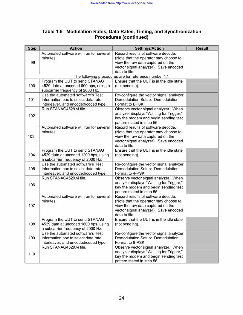
99
Automated software will run for several minutes.
Record results of software decode. (Note that the operator may choose to view the raw data captured on the vector signal analyzer). Save encoded data to file.
The following procedures are for reference number 17.
100 Program the UUT to send STANAG 4529 data at uncoded 600 bps, using a subcarrier frequency of 2000 Hz.
Ensure that the UUT is in the idle state (not sending).
101 Use the automated software’s Test Information box to select data rate, interleaver, and uncoded/coded type.
Re-configure the vector signal analyzer Demodulation Setup: Demodulation Format to BPSK.
102
Run STANAG4529.vi file. Observe vector signal analyzer. When analyzer displays “Waiting for Trigger,” key the modem and begin sending test pattern stated in step 56.
103
Automated software will run for several minutes.
Record results of software decode. (Note that the operator may choose to view the raw data captured on the vector signal analyzer). Save encoded data to file.
104 Program the UUT to send STANAG 4529 data at uncoded 1200 bps, using a subcarrier frequency of 2000 Hz.
Ensure that the UUT is in the idle state (not sending).
105 Use the automated software’s Test Information box to select data rate, interleaver, and uncoded/coded type.
Re-configure the vector signal analyzer Demodulation Setup: Demodulation Format to 4-PSK.
106
Run STANAG4529.vi file. Observe vector signal analyzer. When analyzer displays “Waiting for Trigger,” key the modem and begin sending test pattern stated in step 56.
107
Automated software will run for several minutes.
Record results of software decode. (Note that the operator may choose to view the raw data captured on the vector signal analyzer). Save encoded data to file.
108 Program the UUT to send STANAG 4529 data at uncoded 1800 bps, using a subcarrier frequency of 2000 Hz.
Ensure that the UUT is in the idle state (not sending).
109 Use the automated software’s Test Information box to select data rate, interleaver, and uncoded/coded type.
Re-configure the vector signal analyzer Demodulation Setup: Demodulation Format to 8-PSK.
110
Run STANAG4529.vi file. Observe vector signal analyzer. When analyzer displays “Waiting for Trigger,” key the modem and begin sending test pattern stated in step 56.
Downloaded from http://www.everyspec.com

25
Step Action Settings/Action Result
111
Automated software will run for several minutes.
Record results of software decode. (Note that the operator may choose to view the raw data captured on the vector signal analyzer). Save encoded data to file.
Downloaded from http://www.everyspec.com

26
Table 1.6. Modulation Rates, Data Rates, Timing, and Synchronization Procedures (continued)
Step Action Settings/Action Result
The following procedures are for reference number 3.
112
Configure vector signal analyzer. Frequency Center: 800 Hz Span: 1.24 kHz Time Result Length: 2000 symbols Search Length: 853.33 ms Sync Setup
Pattern: 01011001111100011011 Offset: 0 symbols
Instrument Mode Digital Demodulation Demodulation Setup Demodulation format: BPSK Symbol Rate: 1.2 kHz Result Length: 1000 symbols Reference Filter: Root Raised Cos Meas Filter: Root Raised Cos Alpha: 0.16 Sweep: Single Trigger Trigger Type: IF CH1 Configure state constellation diagram as given in figure 1.1
113 Configure UUT. Configure the UUT to transmit with
coded, 300 bps, short interleaving. Configure the subcarier frequency to 800 Hz.
114
Configure BERT. Configure the BERT to transmit: “THE QUICK BROWN FOX JUMPS OVER THE LAZY DOG 0123456789” using 7-bit ASCII.
115 Transmit data. Allow for the BERT to transmit its data
through the UUT. Save the data captured on the vector signal analyzer to a file.
116
Run STANAG4529.vi file. Observe vector signal analyzer. When analyzer displays “Waiting for Trigger,” key the modem and begin sending test pattern in step 114.
117
Automated software will run for several minutes.
Record results of software decode. (Note that the operator may choose to view the raw data captured on the vector signal analyzer). Save encoded data to file.
Downloaded from http://www.everyspec.com

27
Table 1.6. Modulation Rates, Data Rates, Timing, and Synchronization Procedures (continued)
Step Action Settings/Action Result
118 Re-configure center frequency on vector signal analyzer.
Re-configure the vector signal analyzer’s center frequency setting to 900 Hz.
119
Configure UUT. Configure the UUT to transmit with coded, 300 bps, short interleaving. Configure the subcarier frequency to 900 Hz.
120
Configure BERT. Configure the BERT to transmit: “THE QUICK BROWN FOX JUMPS OVER THE LAZY DOG 0123456789” using 7-bit ASCII.
121
Transmit data. Allow for the BERT to transmit its data through the UUT. Save the data captured on the vector signal analyzer to a file.
122
Run STANAG4529.vi file. Observe vector signal analyzer. When analyzer displays “Waiting for Trigger,” key the modem and begin sending test pattern in step 114.
123
Automated software will run for several minutes.
Record results of software decode. (Note that the operator may choose to view the raw data captured on the vector signal analyzer). Save encoded data to file.
124 Re-configure center frequency on vector signal analyzer.
Re-configure the vector signal analyzer’s center frequency setting to 1000 Hz.
125
Configure UUT. Configure the UUT to transmit with coded, 300 bps, short interleaving. Configure the subcarier frequency to 1000 Hz.
126
Configure BERT. Configure the BERT to transmit: “THE QUICK BROWN FOX JUMPS OVER THE LAZY DOG 0123456789” using 7-bit ASCII.
127
Transmit data. Allow for the BERT to transmit its data through the UUT. Save the data captured on the vector signal analyzer to a file.
128
Run STANAG4529.vi file. Observe vector signal analyzer. When analyzer displays “Waiting for Trigger,” key the modem and begin sending test pattern in step 114.
Downloaded from http://www.everyspec.com

28
Table 1.6. Modulation Rates, Data Rates, Timing, and Synchronization Procedures (continued)
Step Action Settings/Action Result
129
Automated software will run for several minutes.
Record results of software decode. (Note that the operator may choose to view the raw data captured on the vector signal analyzer). Save encoded data to file.
130 Re-configure center frequency on vector signal analyzer.
Re-configure the vector signal analyzer’s center frequency setting to 1100 Hz.
131
Configure UUT. Configure the UUT to transmit with coded, 300 bps, short interleaving. Configure the subcarier frequency to 1100 Hz.
132
Configure BERT. Configure the BERT to transmit: “THE QUICK BROWN FOX JUMPS OVER THE LAZY DOG 0123456789” using 7-bit ASCII.
133
Transmit data. Allow for the BERT to transmit its data through the UUT. Save the data captured on the vector signal analyzer to a file.
134
Run STANAG4529.vi file. Observe vector signal analyzer. When analyzer displays “Waiting for Trigger,” key the modem and begin sending test pattern in step 114.
135
Automated software will run for several minutes.
Record results of software decode. (Note that the operator may choose to view the raw data captured on the vector signal analyzer). Save encoded data to file.
136 Re-configure center frequency on vector signal analyzer.
Re-configure the vector signal analyzer’s center frequency setting to 1200 Hz.
137
Configure UUT. Configure the UUT to transmit with coded, 300 bps, short interleaving. Configure the subcarier frequency to 1200 Hz.
138
Configure BERT. Configure the BERT to transmit: “THE QUICK BROWN FOX JUMPS OVER THE LAZY DOG 0123456789” using 7-bit ASCII.
139
Transmit data. Allow for the BERT to transmit its data through the UUT. Save the data captured on the vector signal analyzer to a file.
140
Run STANAG4529.vi file. Observe vector signal analyzer. When analyzer displays “Waiting for Trigger,” key the modem and begin sending test pattern in step 114.
Downloaded from http://www.everyspec.com
29
Table 1.6. Modulation Rates, Data Rates, Timing, and Synchronization Procedures (continued)
Step Action Settings/Action Result
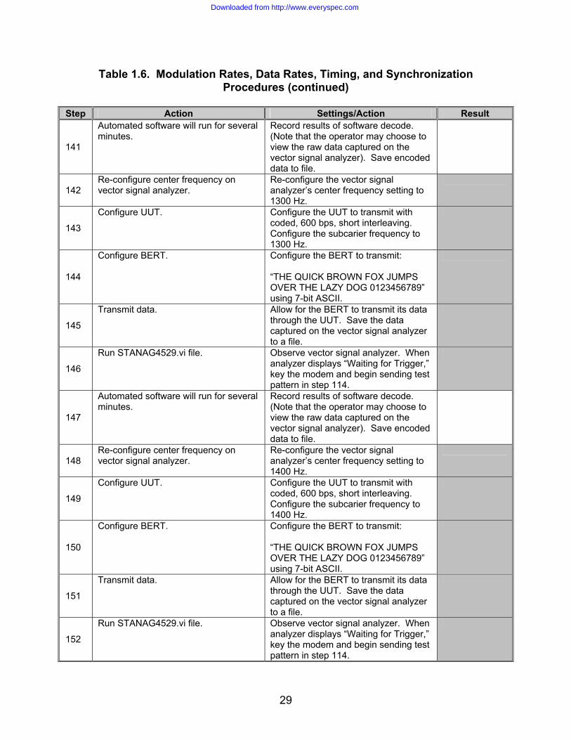
141
Automated software will run for several minutes.
Record results of software decode. (Note that the operator may choose to view the raw data captured on the vector signal analyzer). Save encoded data to file.
142 Re-configure center frequency on vector signal analyzer.
Re-configure the vector signal analyzer’s center frequency setting to 1300 Hz.
143
Configure UUT. Configure the UUT to transmit with coded, 600 bps, short interleaving. Configure the subcarier frequency to 1300 Hz.
144
Configure BERT. Configure the BERT to transmit: “THE QUICK BROWN FOX JUMPS OVER THE LAZY DOG 0123456789” using 7-bit ASCII.
145
Transmit data. Allow for the BERT to transmit its data through the UUT. Save the data captured on the vector signal analyzer to a file.
146
Run STANAG4529.vi file. Observe vector signal analyzer. When analyzer displays “Waiting for Trigger,” key the modem and begin sending test pattern in step 114.
147
Automated software will run for several minutes.
Record results of software decode. (Note that the operator may choose to view the raw data captured on the vector signal analyzer). Save encoded data to file.
148 Re-configure center frequency on vector signal analyzer.
Re-configure the vector signal analyzer’s center frequency setting to 1400 Hz.
149
Configure UUT. Configure the UUT to transmit with coded, 600 bps, short interleaving. Configure the subcarier frequency to 1400 Hz.
150
Configure BERT. Configure the BERT to transmit: “THE QUICK BROWN FOX JUMPS OVER THE LAZY DOG 0123456789” using 7-bit ASCII.
151
Transmit data. Allow for the BERT to transmit its data through the UUT. Save the data captured on the vector signal analyzer to a file.
152
Run STANAG4529.vi file. Observe vector signal analyzer. When analyzer displays “Waiting for Trigger,” key the modem and begin sending test pattern in step 114.
Downloaded from http://www.everyspec.com

30
Table 1.6. Modulation Rates, Data Rates, Timing, and Synchronization Procedures (continued)
Step Action Settings/Action Result
153
Automated software will run for several minutes.
Record results of software decode. (Note that the operator may choose to view the raw data captured on the vector signal analyzer). Save encoded data to file.
154 Re-configure center frequency on vector signal analyzer.
Re-configure the vector signal analyzer’s center frequency setting to 1500 Hz.
155
Configure UUT. Configure the UUT to transmit with coded, 600 bps, short interleaving. Configure the subcarier frequency to 1500 Hz.
156
Configure BERT. Configure the BERT to transmit: “THE QUICK BROWN FOX JUMPS OVER THE LAZY DOG 0123456789” using 7-bit ASCII.
157
Transmit data. Allow for the BERT to transmit its data through the UUT. Save the data captured on the vector signal analyzer to a file.
158
Run STANAG4529.vi file. Observe vector signal analyzer. When analyzer displays “Waiting for Trigger,” key the modem and begin sending test pattern in step 114.
159
Automated software will run for several minutes.
Record results of software decode. (Note that the operator may choose to view the raw data captured on the vector signal analyzer). Save encoded data to file.
160 Re-configure center frequency on vector signal analyzer.
Re-configure the vector signal analyzer’s center frequency setting to 1600 Hz.
161
Configure UUT. Configure the UUT to transmit with coded, 300 bps, short interleaving. Configure the subcarier frequency to 1600 Hz.
162
Configure BERT. Configure the BERT to transmit: “THE QUICK BROWN FOX JUMPS OVER THE LAZY DOG 0123456789” using 7-bit ASCII.
163
Transmit data. Allow for the BERT to transmit its data through the UUT. Save the data captured on the vector signal analyzer to a file.
164
Run STANAG4529.vi file. Observe vector signal analyzer. When analyzer displays “Waiting for Trigger,” key the modem and begin sending test pattern in step 114.
Downloaded from http://www.everyspec.com

31
Table 1.6. Modulation Rates, Data Rates, Timing, and Synchronization Procedures (continued)
Step Action Settings/Action Result
165
Automated software will run for several minutes.
Record results of software decode. (Note that the operator may choose to view the raw data captured on the vector signal analyzer). Save encoded data to file.
166 Re-configure center frequency on vector signal analyzer.
Re-configure the vector signal analyzer’s center frequency setting to 1700 Hz.
167
Configure UUT. Configure the UUT to transmit with coded, 300 bps, short interleaving. Configure the subcarier frequency to 1700 Hz.
168
Configure BERT. Configure the BERT to transmit: “THE QUICK BROWN FOX JUMPS OVER THE LAZY DOG 0123456789” using 7-bit ASCII.
169
Transmit data. Allow for the BERT to transmit its data through the UUT. Save the data captured on the vector signal analyzer to a file.
170
Run STANAG4529.vi file. Observe vector signal analyzer. When analyzer displays “Waiting for Trigger,” key the modem and begin sending test pattern in step 114.
171
Automated software will run for several minutes.
Record results of software decode. (Note that the operator may choose to view the raw data captured on the vector signal analyzer). Save encoded data to file.
172 Re-configure center frequency on vector signal analyzer.
Re-configure the vector signal analyzer’s center frequency setting to 1800 Hz.
173
Configure UUT. Configure the UUT to transmit with coded, 300 bps, short interleaving. Configure the subcarier frequency to 1800 Hz.
174
Configure BERT. Configure the BERT to transmit: “THE QUICK BROWN FOX JUMPS OVER THE LAZY DOG 0123456789” using 7-bit ASCII.
175
Transmit data. Allow for the BERT to transmit its data through the UUT. Save the data captured on the vector signal analyzer to a file.
176
Run STANAG4529.vi file. Observe vector signal analyzer. When analyzer displays “Waiting for Trigger,” key the modem and begin sending test pattern in step 114.
Downloaded from http://www.everyspec.com

32
Table 1.6. Modulation Rates, Data Rates, Timing, and Synchronization Procedures (continued)
Step Action Settings/Action Result
177
Automated software will run for several minutes.
Record results of software decode. (Note that the operator may choose to view the raw data captured on the vector signal analyzer). Save encoded data to file.
178 Re-configure center frequency on vector signal analyzer.
Re-configure the vector signal analyzer’s center frequency setting to 1900 Hz.
179
Configure UUT. Configure the UUT to transmit with coded, 300 bps, short interleaving. Configure the subcarier frequency to 1900 Hz.
180
Configure BERT. Configure the BERT to transmit: “THE QUICK BROWN FOX JUMPS OVER THE LAZY DOG 0123456789” using 7-bit ASCII.
181
Transmit data. Allow for the BERT to transmit its data through the UUT. Save the data captured on the vector signal analyzer to a file.
182
Run STANAG4529.vi file. Observe vector signal analyzer. When analyzer displays “Waiting for Trigger,” key the modem and begin sending test pattern in step 114.
183
Automated software will run for several minutes.
Record results of software decode. (Note that the operator may choose to view the raw data captured on the vector signal analyzer). Save encoded data to file.
184 Re-configure center frequency on vector signal analyzer.
Re-configure the vector signal analyzer’s center frequency setting to 2000 Hz.
185
Configure UUT. Configure the UUT to transmit with coded, 300 bps, short interleaving. Configure the subcarier frequency to 2000 Hz.
186
Configure BERT. Configure the BERT to transmit: “THE QUICK BROWN FOX JUMPS OVER THE LAZY DOG 0123456789” using 7-bit ASCII.
187
Transmit data. Allow for the BERT to transmit its data through the UUT. Save the data captured on the vector signal analyzer to a file.
188
Run STANAG4529.vi file. Observe vector signal analyzer. When analyzer displays “Waiting for Trigger,” key the modem and begin sending test pattern in step 114.
Downloaded from http://www.everyspec.com

33
Table 1.6. Modulation Rates, Data Rates, Timing, and Synchronization Procedures (continued)
Step Action Settings/Action Result
189
Automated software will run for several minutes.
Record results of software decode. (Note that the operator may choose to view the raw data captured on the vector signal analyzer). Save encoded data to file.
190 Re-configure center frequency on vector signal analyzer.
Re-configure the vector signal analyzer’s center frequency setting to 2100 Hz.
191
Configure UUT. Configure the UUT to transmit with coded, 300 bps, short interleaving. Configure the subcarier frequency to 2100 Hz.
192
Configure BERT. Configure the BERT to transmit: “THE QUICK BROWN FOX JUMPS OVER THE LAZY DOG 0123456789” using 7-bit ASCII.
193
Transmit data. Allow for the BERT to transmit its data through the UUT. Save the data captured on the vector signal analyzer to a file.
194
Run STANAG4529.vi file. Observe vector signal analyzer. When analyzer displays “Waiting for Trigger,” key the modem and begin sending test pattern in step 114.
195
Automated software will run for several minutes.
Record results of software decode. (Note that the operator may choose to view the raw data captured on the vector signal analyzer). Save encoded data to file.
196 Re-configure center frequency on vector signal analyzer.
Re-configure the vector signal analyzer’s center frequency setting to 2200 Hz.
197
Configure UUT. Configure the UUT to transmit with coded, 300 bps, short interleaving. Configure the subcarier frequency to 2200 Hz.
198
Configure BERT. Configure the BERT to transmit: “THE QUICK BROWN FOX JUMPS OVER THE LAZY DOG 0123456789” using 7-bit ASCII.
199
Transmit data. Allow for the BERT to transmit its data through the UUT. Save the data captured on the vector signal analyzer to a file.
200
Run STANAG4529.vi file. Observe vector signal analyzer. When analyzer displays “Waiting for Trigger,” key the modem and begin sending test pattern in step 114.
Downloaded from http://www.everyspec.com

34
Table 1.6. Modulation Rates, Data Rates, Timing, and Synchronization Procedures (continued)
Step Action Settings/Action Result
201
Automated software will run for several minutes.
Record results of software decode. (Note that the operator may choose to view the raw data captured on the vector signal analyzer). Save encoded data to file.
202 Re-configure center frequency on vector signal analyzer.
Re-configure the vector signal analyzer’s center frequency setting to 2300 Hz.
203
Configure UUT. Configure the UUT to transmit with coded, 300 bps, short interleaving. Configure the subcarier frequency to 2300 Hz.
204
Configure BERT. Configure the BERT to transmit: “THE QUICK BROWN FOX JUMPS OVER THE LAZY DOG 0123456789” using 7-bit ASCII.
205
Transmit data. Allow for the BERT to transmit its data through the UUT. Save the data captured on the vector signal analyzer to a file.
206
Run STANAG4529.vi file. Observe vector signal analyzer. When analyzer displays “Waiting for Trigger,” key the modem and begin sending test pattern in step 114.
207
Automated software will run for several minutes.
Record results of software decode. (Note that the operator may choose to view the raw data captured on the vector signal analyzer). Save encoded data to file.
208 Re-configure center frequency on vector signal analyzer.
Re-configure the vector signal analyzer’s center frequency setting to 2400 Hz.
209
Configure UUT. Configure the UUT to transmit with coded, 300 bps, short interleaving. Configure the subcarier frequency to 2400 Hz.
210
Configure BERT. Configure the BERT to transmit: “THE QUICK BROWN FOX JUMPS OVER THE LAZY DOG 0123456789” using 7-bit ASCII.
211
Transmit data. Allow for the BERT to transmit its data through the UUT. Save the data captured on the vector signal analyzer to a file.
212
Run STANAG4529.vi file. Observe vector signal analyzer. When analyzer displays “Waiting for Trigger,” key the modem and begin sending test pattern in step 114.
Downloaded from http://www.everyspec.com
35
Table 1.6. Modulation Rates, Data Rates, Timing, and Synchronization Procedures (continued)
Step Action Settings/Action Result
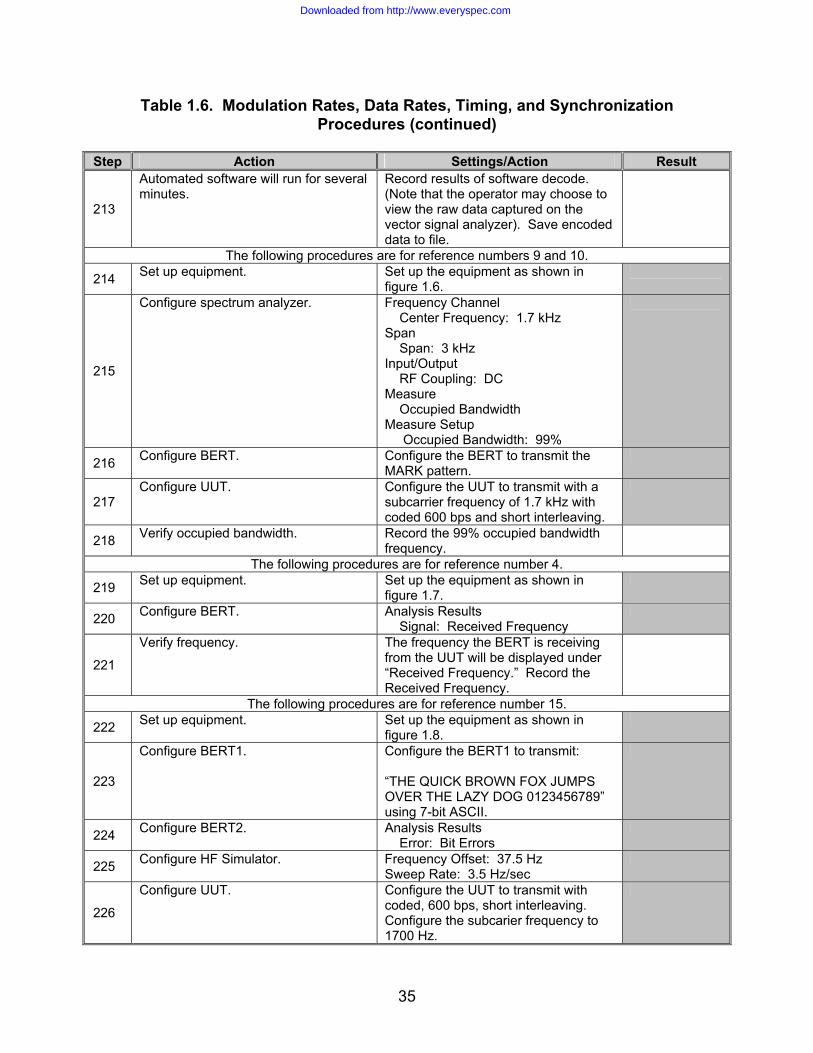
213
Automated software will run for several minutes.
Record results of software decode. (Note that the operator may choose to view the raw data captured on the vector signal analyzer). Save encoded data to file.
The following procedures are for reference numbers 9 and 10.
214 Set up equipment. Set up the equipment as shown in figure 1.6.
215
Configure spectrum analyzer. Frequency Channel Center Frequency: 1.7 kHz Span Span: 3 kHz Input/Output RF Coupling: DC Measure Occupied Bandwidth Measure Setup Occupied Bandwidth: 99%
216 Configure BERT. Configure the BERT to transmit the MARK pattern.
217 Configure UUT. Configure the UUT to transmit with a
subcarrier frequency of 1.7 kHz with coded 600 bps and short interleaving.
218 Verify occupied bandwidth. Record the 99% occupied bandwidth frequency.
The following procedures are for reference number 4.
219 Set up equipment. Set up the equipment as shown in figure 1.7.
220 Configure BERT. Analysis Results Signal: Received Frequency
221
Verify frequency. The frequency the BERT is receiving from the UUT will be displayed under “Received Frequency.” Record the Received Frequency.
The following procedures are for reference number 15.
222 Set up equipment. Set up the equipment as shown in figure 1.8.
223
Configure BERT1. Configure the BERT1 to transmit: “THE QUICK BROWN FOX JUMPS OVER THE LAZY DOG 0123456789” using 7-bit ASCII.
224 Configure BERT2. Analysis Results Error: Bit Errors
225 Configure HF Simulator. Frequency Offset: 37.5 Hz Sweep Rate: 3.5 Hz/sec
226
Configure UUT. Configure the UUT to transmit with coded, 600 bps, short interleaving. Configure the subcarier frequency to 1700 Hz.
Downloaded from http://www.everyspec.com

36
Table 1.6. Modulation Rates, Data Rates, Timing, and Synchronization Procedures (continued)
Step Action Settings/Action Result
227 Run test. Program BERT1 to transmit its
message through the UUT for 5 minutes.
228 Determine bit errors. Record the number of bit errors received by BERT2.
Legend: ASCII—American Standard Code for Information Interchange; BERT—Bit Error Rate Tester; bps—bits per second; BPSK—Binary Phase Shift Keying; CH1—Channel 1; Cos—Cosine; DC—Direct Current; FEC—Forward Error Correction; GPIB—General Purpose Interface Bus; HF—High Frequency; Hz—Hertz; IF—Intermediate Frequency; JITC—Joint Interoperability Test Command; kHz—Kilohertz; Meas—Measured; ms—millisecond; PSK—Phase Shift Keying; RF—Radio Frequency; sec—second; STANAG—Standardization Agreement; Sync—Synchronization; UUT—Unit Under Test
Downloaded from http://www.everyspec.com
37
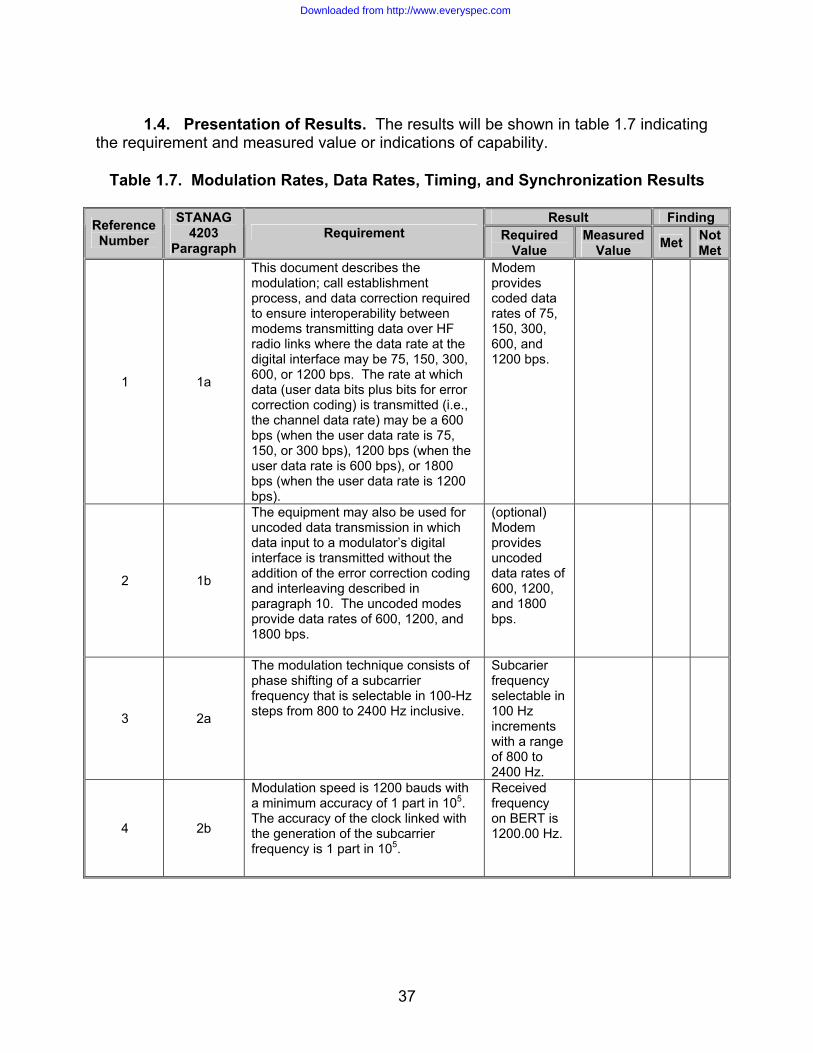
1.4. Presentation of Results. The results will be shown in table 1.7 indicating
the requirement and measured value or indications of capability.
Table 1.7. Modulation Rates, Data Rates, Timing, and Synchronization Results
Result Finding Reference Number
STANAG 4203
Paragraph Requirement Required
Value Measured
Value Met Not Met
1 1a
This document describes the modulation; call establishment process, and data correction required to ensure interoperability between modems transmitting data over HF radio links where the data rate at the digital interface may be 75, 150, 300, 600, or 1200 bps. The rate at which data (user data bits plus bits for error correction coding) is transmitted (i.e., the channel data rate) may be a 600 bps (when the user data rate is 75, 150, or 300 bps), 1200 bps (when the user data rate is 600 bps), or 1800 bps (when the user data rate is 1200 bps).
Modem provides coded data rates of 75, 150, 300, 600, and 1200 bps.
2 1b
The equipment may also be used for uncoded data transmission in which data input to a modulator’s digital interface is transmitted without the addition of the error correction coding and interleaving described in paragraph 10. The uncoded modes provide data rates of 600, 1200, and 1800 bps.
(optional) Modem provides uncoded data rates of 600, 1200, and 1800 bps.
3 2a
The modulation technique consists of phase shifting of a subcarrier frequency that is selectable in 100-Hz steps from 800 to 2400 Hz inclusive.
Subcarier frequency selectable in 100 Hz increments with a range of 800 to 2400 Hz.
4 2b
Modulation speed is 1200 bauds with a minimum accuracy of 1 part in 105. The accuracy of the clock linked with the generation of the subcarrier frequency is 1 part in 105.
Received frequency on BERT is 1200.00 Hz.
Downloaded from http://www.everyspec.com
38
Table 1.7. Modulation Rates, Data Rates, Timing, and Synchronization Results (continued)
Result Finding Reference
Number
STANAG 4203
Paragraph Requirement Required
Value Measured
Value Met Not Met
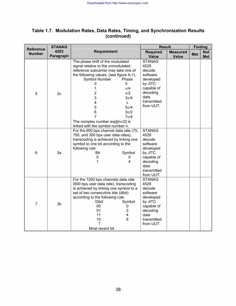
5 2c
The phase shift of the modulated signal relative to the unmodulated reference subcarrier may take one of the following values. (see figure A-1). Symbol Number Phase 0 0 1 π/4 2 π/2 3 3π/4 4 π 5 5π/4 6 3π/2 7 7π/4 The complex number exp[jnπ/2] is linked with the symbol number n.
STANAG 4529 decode software developed by JITC capable of decoding data transmitted from UUT.
6 3a
For the 600 bps channel data rate (75, 150, and 300 bps user data rates), transcoding is achieved by linking one symbol to one bit according to the following rule: Bit Symbol 0 0 1 4
STANAG 4529 decode software developed by JITC capable of decoding data transmitted from UUT.
7 3b
For the 1200 bps channels data rate (600 bps user data rate), transcoding is achieved by linking one symbol to a set of two consecutive bits (dibit) according to the following rule: Dibit Symbol 00 0 01 2 11 4 10 6 ↑ Most recent bit
STANAG 4529 decode software developed by JITC capable of decoding data transmitted from UUT.
Downloaded from http://www.everyspec.com

39
Table 1.7. Modulation Rates, Data Rates, Timing, and Synchronization Results
(continued)
Result Finding Reference Number
STANAG 4203
Paragraph Requirement Required
Value Measured
Value Met Not Met
8 3c
For the 1800 bps channel data rate (1200 bps user data rate), transcoding is achieved by linking one symbol to a set of three consecutive bits (tribit) according to the following rule: Tribit Symbol
000 1 001 0 010 2 011 3 100 6 101 7 110 5 111 4 ↑
Most recent bit
STANAG 4529 decode software developed by JITC capable of decoding data transmitted from UUT.
9 4
The power spectral density of the modulated signal shall be centered on a frequency that is selectable in 100-Hz steps from 800 Hz to 2400 Hz inclusive, with a default value of 1700 Hz.
Power spectral density centered at 1700 Hz.
10 4
Filtering shall be applied as necessary so that 99% of the output power is within 1240 Hz.
99% output power contained within 1240 Hz.
11 5
The symbols to be transmitted are structured in recurrent frames 213.3 ms is length. A frame consists of 256 symbols. A frame can be broken down into: 80 symbols for synchronization, 48 reference symbols and 128 data symbols. The 176 reference and data symbols are scrambled by a scrambling sequence with eight-phase-states of length 176. The reference and data symbols are formed into 4 blocks: the first 3 consist of 32 data symbols followed by 16 reference symbols: the last block consists of 32 symbols. The reference symbols area all symbol number 0.
STANAG 4529 decode software developed by JITC capable of decoding data transmitted from UUT.
Downloaded from http://www.everyspec.com
40
Table 1.7. Modulation Rates, Data Rates, Timing, and Synchronization Results (continued)
Result Finding Reference
Number
STANAG 4203
Paragraph Requirement Required
Value Measured
Value Met Not Met
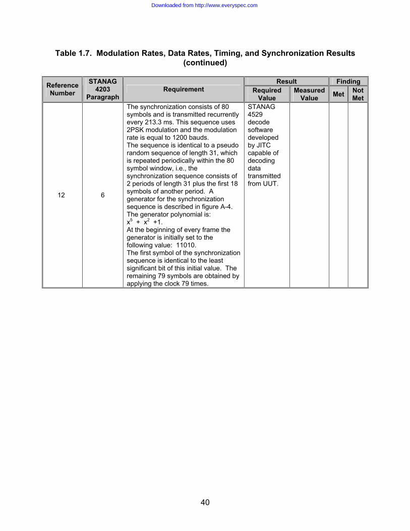
12 6
The synchronization consists of 80 symbols and is transmitted recurrently every 213.3 ms. This sequence uses 2PSK modulation and the modulation rate is equal to 1200 bauds. The sequence is identical to a pseudo random sequence of length 31, which is repeated periodically within the 80 symbol window, i.e., the synchronization sequence consists of 2 periods of length 31 plus the first 18 symbols of another period. A generator for the synchronization sequence is described in figure A-4. The generator polynomial is: x5 + x2 +1. At the beginning of every frame the generator is initially set to the following value: 11010. The first symbol of the synchronization sequence is identical to the least significant bit of this initial value. The remaining 79 symbols are obtained by applying the clock 79 times.
STANAG 4529 decode software developed by JITC capable of decoding data transmitted from UUT.
Downloaded from http://www.everyspec.com

41
Table 1.7. Modulation Rates, Data Rates, Timing, and Synchronization Results (continued)
Result Finding Reference
Number
STANAG 4203
Paragraph Requirement Required
Value Measured
Value Met Not Met
13 7
The scrambling sequence is composed of 176 symbols and is repeated every 213.3 ms. This sequence is transmitted in eight-phase-state modulation at the rate of 1200 bauds. Data scrambling by an eight-phase-state sequence is done to maintain commonality with STANAG 4285 implementations. The scrambling signal generator is shown in figure A-5. The symbols are formed by means of a pseudo-random code of length 511, the generator polynomial of which is: x9 + x4 + 1. The generator is initialized to 1 at the start of each frame. A symbol is derived from the triplet consisting of the last three bits in the PN register, i.e., x0 x1 x2 by the following relationship: Scrambling symbol Bk = exp[jnπ/4] Where: n = 4x2 +2x1 + x0
x0 = 0 or 1 x1 = 0 or 1 x2 = 0 or 1 Generation from one symbol to the next is by successive shifting of the PN register by three positions.
STANAG 4529 decode software developed by JITC capable of decoding data transmitted from UUT.
14 8
The scrambling operation is carried out on reference and data symbols only, not on the synchronization sequence. This operation consists of modulo 8 addition of the data symbol number to the scrambling symbol number; this amounts to complex multiplication of the data symbol by the scrambling symbol.
STANAG 4529 decode software developed by JITC capable of decoding data transmitted from UUT.
Downloaded from http://www.everyspec.com

42
Table 1.7. Modulation Rates, Data Rates, Timing, and Synchronization Results (continued)
Result Finding Reference
Number
STANAG 4203
Paragraph Requirement Required
Value Measured
Value Met Not Met
15 9
The modem must be capable of tolerating a frequency error of +/-37.5 Hz between the transmission and reception of HF carriers (transmitter/receiver frequency error and Doppler shift included) and rate of frequency change of up to 3.5 Hz/sec.
0 Bit Errors.
Downloaded from http://www.everyspec.com

43
Table 1.7. Modulation Rates, Data Rates, Timing, and Synchronization Results (continued)
Result Finding Reference
Number
STANAG 4203
Paragraph Requirement Required
Value Measured
Value Met Not Met
16 10
For the error correction modes defined in this STANAG, the error correction coding used shall be the rate ½, constraint length 7 convolutional coding as described STANAG 4285, annex E. For each user data rate described in this STANAG (i.e., 75, 150, 300, 600, and 1200 bps) the coding, interleaving, and flush bits shall be as described for the higher data rate in STANAG 4285, annex E. The changes necessary to allow 1240-Hz operation are explicitly shown below: The error correction coding used shall be as in STANAG 4285, annex E, section 2 with the following changes: See figure A-6. The interleaving shall be as described in STANAG 4285, annex E, section 3 with the following different parameters: Number of rows: I = 32 for all data rates Delay increment “j” for each successive row: Total Interleaving Delay: Data rates 20.48 sec 1.706 sec 1200 bps 48 4 600 bps 24 2 300, 150, 12 1 and 75 bps Interleaver synchronization shall be as described in STANAG 4285, annex E, part 4 with no changes. The initialization and message protocol for use with coding and interleaving shall be as described in STANAG 4285, annex E, part 5 with the following difference: The number of flush zeros for each of the data rates and the two interleaver lengths are as follows: Interleaver Delay Data rate 20.48 sec 1.706 sec 1200 bps 24678 2150 600 bps 12390 1126 300 bps 6246 614 150 bps 3174 358 75 bps 1638 230
STANAG 4529 decode software developed by JITC capable of decoding data transmit-ted from UUT.
Downloaded from http://www.everyspec.com

44
Table 1.7. Modulation Rates, Data Rates, Timing, and Synchronization Results (continued)
Result Finding Reference
Number
STANAG 4203
Paragraph Requirement Required
Value Measured
Value Met Not Met
17 11
Modems shall provide uncoded data transmission modes, in which the coding, interleaving, and associated initialization and message protocols (described in section 10) are not applied to the data transmitted. Uncoded data modes shall retain all other characteristics described In this STANAG. Uncoded data rates of 600, 1200, and 1800 bps shall be provided.
STANAG 4529 decode software developed by JITC capable of decoding data transmit-ted from UUT.
Legend: BERT—Bit Error Rate Tester; bps—bits per second; HF—High Frequency; Hz—hertz; JITC—Joint Interoperability Test Command; ms—millisecond; PN—Pseudo-random Numerical; PSK—Phase Shift Keying; sec—second; STANAG–Standardization Agreement; UUT—Unit Under Test
Downloaded from http://www.everyspec.com

45
(This page intentionally left blank.)
Downloaded from http://www.everyspec.com

A-1
APPENDIX A
ACRONYMS
Downloaded from http://www.everyspec.com

A-2
(This page intentionally left blank.)
Downloaded from http://www.everyspec.com
A-3
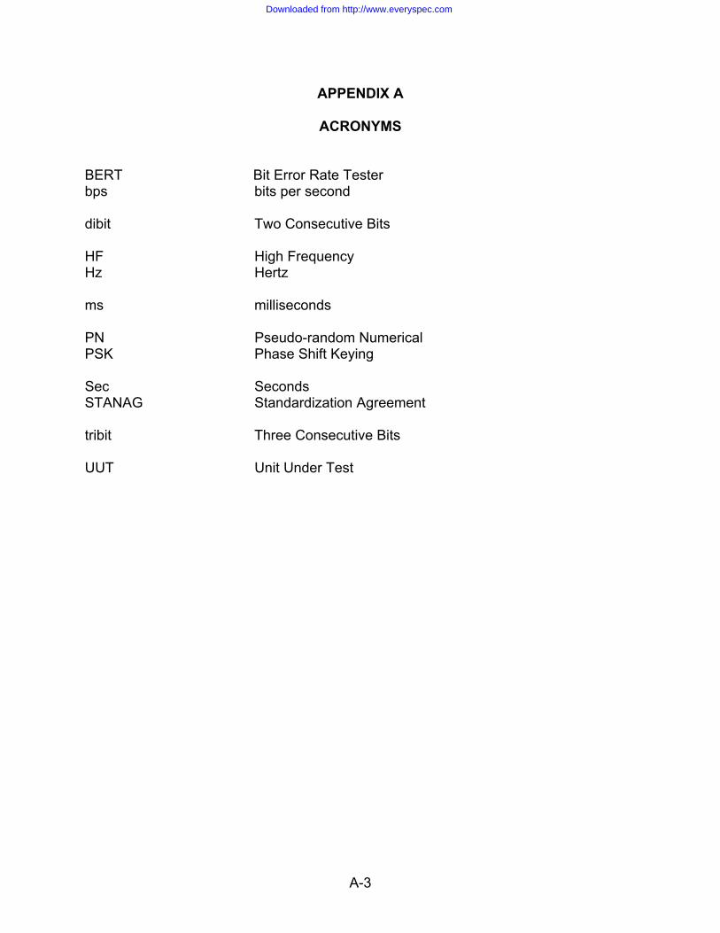
APPENDIX A
ACRONYMS BERT Bit Error Rate Tester bps bits per second dibit Two Consecutive Bits HF High Frequency Hz Hertz ms milliseconds PN Pseudo-random Numerical PSK Phase Shift Keying Sec Seconds STANAG Standardization Agreement tribit Three Consecutive Bits UUT Unit Under Test
Downloaded from http://www.everyspec.com

A-4
(This page intentionally left blank.)
Downloaded from http://www.everyspec.com

B-1
APPENDIX B
STANAG 4529 REQUIREMENTS MATRIX
Downloaded from http://www.everyspec.com

B-2
(This page intentionally left blank.)
Downloaded from http://www.everyspec.com
B-3
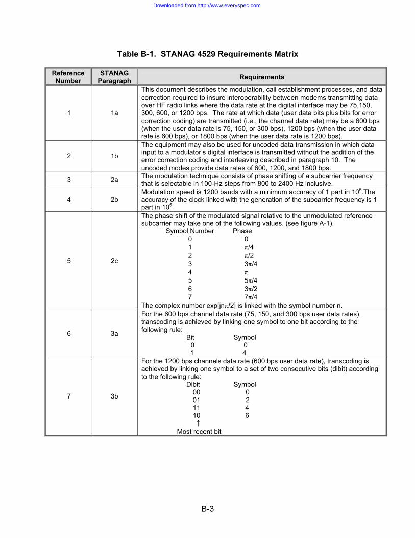
Table B-1. STANAG 4529 Requirements Matrix Reference Number
STANAG Paragraph Requirements
1 1a
This document describes the modulation, call establishment processes, and data correction required to insure interoperability between modems transmitting data over HF radio links where the data rate at the digital interface may be 75,150, 300, 600, or 1200 bps. The rate at which data (user data bits plus bits for error correction coding) are transmitted (i.e., the channel data rate) may be a 600 bps (when the user data rate is 75, 150, or 300 bps), 1200 bps (when the user data rate is 600 bps), or 1800 bps (when the user data rate is 1200 bps).
2 1b
The equipment may also be used for uncoded data transmission in which data input to a modulator’s digital interface is transmitted without the addition of the error correction coding and interleaving described in paragraph 10. The uncoded modes provide data rates of 600, 1200, and 1800 bps.
3 2a The modulation technique consists of phase shifting of a subcarrier frequency that is selectable in 100-Hz steps from 800 to 2400 Hz inclusive.
4 2b Modulation speed is 1200 bauds with a minimum accuracy of 1 part in 105.The accuracy of the clock linked with the generation of the subcarrier frequency is 1 part in 105.
5 2c
The phase shift of the modulated signal relative to the unmodulated reference subcarrier may take one of the following values. (see figure A-1). Symbol Number Phase 0 0 1 π/4 2 π/2 3 3π/4 4 π 5 5π/4 6 3π/2 7 7π/4 The complex number exp[jnπ/2] is linked with the symbol number n.
6 3a
For the 600 bps channel data rate (75, 150, and 300 bps user data rates), transcoding is achieved by linking one symbol to one bit according to the following rule: Bit Symbol
0 0 1 4
7 3b
For the 1200 bps channels data rate (600 bps user data rate), transcoding is achieved by linking one symbol to a set of two consecutive bits (dibit) according to the following rule: Dibit Symbol
00 0 01 2 11 4 10 6 ↑
Most recent bit
Downloaded from http://www.everyspec.com
B-4
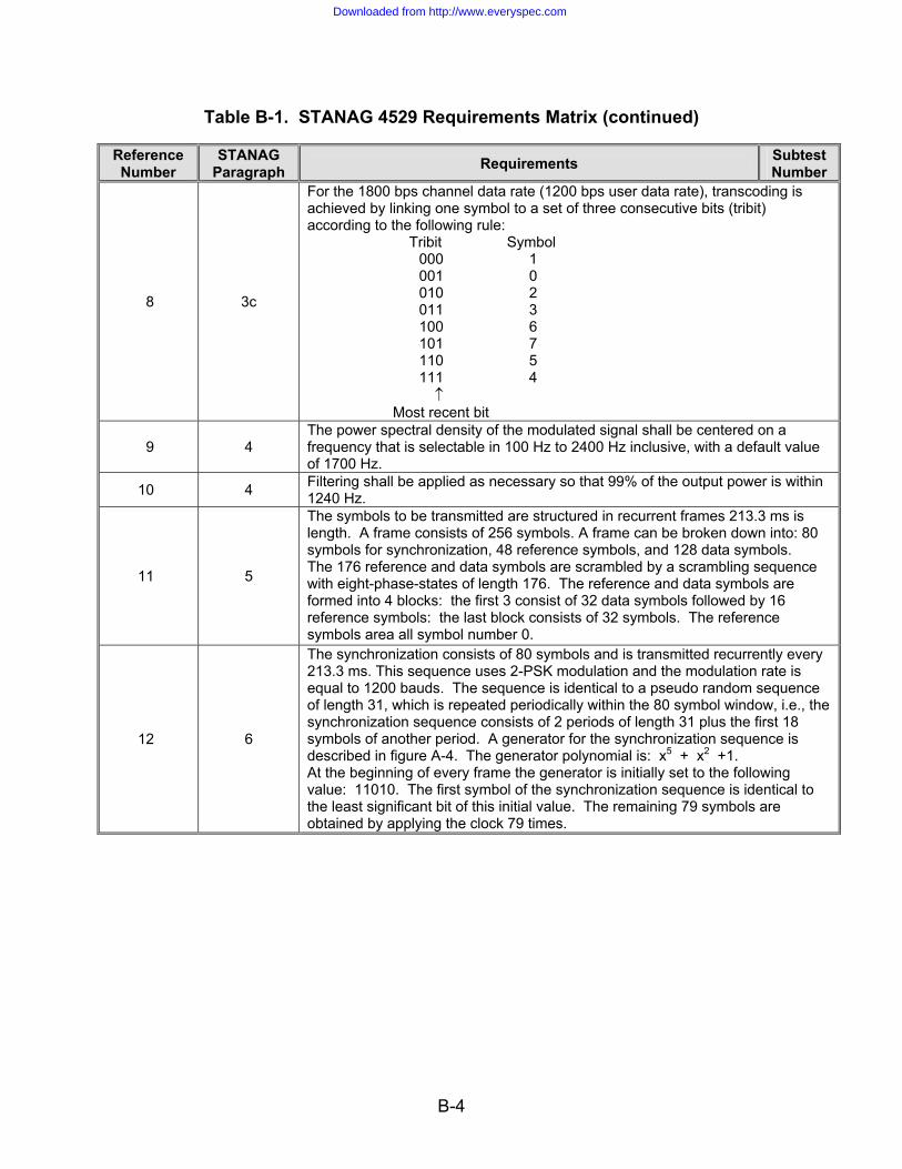
Table B-1. STANAG 4529 Requirements Matrix (continued) Reference Number
STANAG Paragraph Requirements Subtest
Number
8 3c
For the 1800 bps channel data rate (1200 bps user data rate), transcoding is achieved by linking one symbol to a set of three consecutive bits (tribit) according to the following rule: Tribit Symbol
000 1 001 0 010 2 011 3 100 6 101 7 110 5 111 4 ↑
Most recent bit
9 4 The power spectral density of the modulated signal shall be centered on a frequency that is selectable in 100 Hz to 2400 Hz inclusive, with a default value of 1700 Hz.
10 4 Filtering shall be applied as necessary so that 99% of the output power is within 1240 Hz.
11 5
The symbols to be transmitted are structured in recurrent frames 213.3 ms is length. A frame consists of 256 symbols. A frame can be broken down into: 80 symbols for synchronization, 48 reference symbols, and 128 data symbols. The 176 reference and data symbols are scrambled by a scrambling sequence with eight-phase-states of length 176. The reference and data symbols are formed into 4 blocks: the first 3 consist of 32 data symbols followed by 16 reference symbols: the last block consists of 32 symbols. The reference symbols area all symbol number 0.
12 6
The synchronization consists of 80 symbols and is transmitted recurrently every 213.3 ms. This sequence uses 2-PSK modulation and the modulation rate is equal to 1200 bauds. The sequence is identical to a pseudo random sequence of length 31, which is repeated periodically within the 80 symbol window, i.e., the synchronization sequence consists of 2 periods of length 31 plus the first 18 symbols of another period. A generator for the synchronization sequence is described in figure A-4. The generator polynomial is: x5 + x2 +1. At the beginning of every frame the generator is initially set to the following value: 11010. The first symbol of the synchronization sequence is identical to the least significant bit of this initial value. The remaining 79 symbols are obtained by applying the clock 79 times.
Downloaded from http://www.everyspec.com

B-5
Table B-1. STANAG 4529 Requirements Matrix (continued) Reference Number
STANAG Paragraph Requirements Subtest
Number
13 7
The scrambling sequence is composed of 176 symbols and is repeated every 213.3 ms. This sequence is transmitted in eight-phase-state modulation at the rate of 1200 bauds. Data scrambling by an eight-phase-state sequence is done to maintain commonality with STANAG 4285 implementations. The scrambling signal generator is shown in figure A-5. The symbols are formed by means of a pseudo-random code of length 511, the generator polynomial of which is: x9 + x4 + 1. The generator is initialized to 1 at the start of each frame. A symbol is derived from the triplet consisting of the last three bits in the PN register, i.e., x0 x1 x2 by the following relationship: Scrambling symbol Bk = exp[jnπ/4] Where: n = 4x2 +2x1 + x0
x0 = 0 or 1 x1 = 0 or 1 x2 = 0 or 1 Generation from one symbol to the next is by successive shifting of the PN register by three positions.
14 8
The scrambling operation is carried out on reference and data symbols only, not on the synchronization sequence. This operation consists of module 8 addition of the data symbol number to the scrambling symbol number; this amounts to complex multiplication of the data symbol by the scrambling symbol.
15 9
The modem must be capable of tolerating a frequency error of ±37.5 Hz between the transmission and reception of HF carriers (transmitter/receiver frequency error and Doppler shift included) and rate of frequency change of up to 3.5 Hz/sec.
Downloaded from http://www.everyspec.com

B-6
Table B-1. STANAG 4529 Requirements Matrix (continued) Reference Number
STANAG Paragraph Requirements
16 10
For the error correction modes defined in this STANAG, the error correction coding used shall be the rate ½, constraint length 7 convolutional coding as described STANAG 4285, annex E. For each user data rate described in this STANAG (i.e., 75, 150, 300, 600, and 1200 bps) the coding, interleaving, and flush bits shall be as described for the higher data rate in STANAG 4285, annex E. The changes necessary to allow 1240 Hz operation are explicitly shown below: The error correction coding used shall be as in STANAG 4285, annex E, section 2 with the following changes: The interleaving shall be as described in STANAG 4285, annex E, section 3 with the following different parameters: Number of rows: I = 32 for all data rates Delay increment “j” for each successive row: Total Interleaving Delay Data rates 20.48 sec 1.706 sec 1200 bps 48 4 600 bps 24 2 300, 150, and 75 bps 12 1 Interleaver synchronization shall be as described in STANAG 4285, annex E, part 4 with no changes. The initialization and message protocol for use with coding and interleaving shall be as described in STANAG 4285, annex E, part 5 with the following difference: The number of flush zeros for each of the data rates and the two interleaver lengths are as follows: Interleaver Delay Data rate 20.48 sec 1.706 sec 1200 bps 24678 2150 600 bps 12390 1126 300 bps 6246 614 150 bps 3174 358 75 bps 1638 230
Downloaded from http://www.everyspec.com

B-7
Table B-1. STANAG 4529 Requirements Matrix (continued) Reference Number
STANAG Paragraph Requirements
17 11
Modems shall provide uncoded data transmission modes, in which the coding, interleaving, and associated initialization and message protocols (described in section 10) are not applied to the data transmitted. Uncoded data modes shall retain all other characteristics described In this STANAG. Uncoded data rates of 600, 1200, and 1800 bps shall be provided.
Legend: bps – bits per second; HF – High Frequency; Hz – hertz; ms—millisecond; sec—second; PN—Pseudo-random Numerical; PSK—Phase Shift Keying; STANAG – Standardization Agreement
Downloaded from http://www.everyspec.com

B-8
(This page intentionally left blank.)
Downloaded from http://www.everyspec.com
C-1
APPENDIX C
DATA COLLECTION FORMS
Downloaded from http://www.everyspec.com

C-2
(This page intentionally left blank.)
Downloaded from http://www.everyspec.com

C-3
CONTROL NUMBER: STANAG 4529
CONFORMANCE TEST Event Log Form
DATE: (DD/MM/YY)
Form Number Serial Number Equipment
Nomenclature Call Sign Remarks
DATA ENTRY TECHNICIAN: TEST DIRECTOR:
SIGNATURE: SIGNATURE:
Downloaded from http://www.everyspec.com
C-4
(This page intentionally left blank.)
Downloaded from http://www.everyspec.com
C-5
CONTROL NUMBER:
STANAG 4529 CONFORMANCE TEST
Equipment Configuration Diagram Form
DATE: (DD/MM/YY)
DATA ENTRY TECHNICIAN: TEST DIRECTOR:
SIGNATURE: SIGNATURE:
Downloaded from http://www.everyspec.com

C-6
(This page intentionally left blank.)
Downloaded from http://www.everyspec.com

C-7
CONTROL NUMBER:
STANAG 4529 CONFORMANCE TEST
Event Log Form DATE: (DD/MM/YY)
Time (Local) Initials Event
TEST TECHNICIAN:
DATA ENTRY TECHNICIAN:
TEST DIRECTOR:
Downloaded from http://www.everyspec.com

C-8
(This page intentionally left blank.)
Downloaded from http://www.everyspec.com

C-9
CONTROL NUMBER:
STANAG 4529 Waveform Conformance
Test Plan Form
DATE: (DD/MM/YY)
Equipment: Serial Number:
Description:
Remarks
TEST TECHNICIAN:
DATA ENTRY TECHNICIAN:
TEST DIRECTOR:
Downloaded from http://www.everyspec.com

C-10
(This page intentionally left blank.)
Downloaded from http://www.everyspec.com

C-11
CONTROL NUMBER:
STANAG 4529 CONFORMANCE TEST
Additional Remarks Form DATE: (DD/MM/YY)
Remarks
TEST TECHNICIAN:
DATA ENTRY TECHNICIAN:
TEST DIRECTOR:
Downloaded from http://www.everyspec.com

C-12
(This page intentionally left blank.)
Downloaded from http://www.everyspec.com

D-1
APPENDIX D
STANAG 4529 CONFORMANCE TEST PROCEDURES RESULTS MATRIX
Downloaded from http://www.everyspec.com

D-2
(This page intentionally left blank.)
Downloaded from http://www.everyspec.com
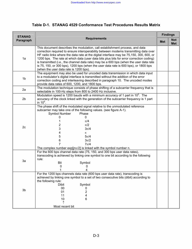
D-3
Table D-1. STANAG 4529 Conformance Test Procedures Results Matrix
Findings STANAG Paragraph Requirements
Met Not Met
1a
This document describes the modulation, call establishment process, and data correction required to ensure interoperability between modems transmitting data over HF radio links where the data rate at the digital interface may be 75,150, 300, 600, or 1200 bps. The rate at which data (user data bits plus bits for error correction coding) is transmitted (i.e., the channel data rate) may be a 600 bps (when the user data rate is 75, 150, or 300 bps), 1200 bps (when the user data rate is 600 bps), or 1800 bps (when the user data rate is 1200 bps).
1b
The equipment may also be used for uncoded data transmission in which data input to a modulator’s digital interface is transmitted without the addition of the error correction coding and interleaving described in paragraph 10. The uncoded modes provide data rates of 600, 1200, and 1800 bps.
2a The modulation technique consists of phase shifting of a subcarrier frequency that is selectable in 100-Hz steps from 800 to 2400 Hz inclusive.
2b Modulation speed is 1200 bauds with a minimum accuracy of 1 part in 105. The accuracy of the clock linked with the generation of the subcarrier frequency is 1 part in 105.
2c
The phase shift of the modulated signal relative to the unmodulated reference subcarrier may take one of the following values. (see figure A-1). Symbol Number Phase 0 0 1 π/4 2 π/2 3 3π/4 4 π 5 5π/4 6 3π/2 7 7π/4 The complex number exp[jnπ/2] is linked with the symbol number n.
3a
For the 600 bps channel data rate (75, 150, and 300 bps user data rates), transcoding is achieved by linking one symbol to one bit according to the following rule: Bit Symbol
0 0 1 4
3b
For the 1200 bps channels data rate (600 bps user data rate), transcoding is achieved by linking one symbol to a set of two consecutive bits (dibit) according to the following rule: Dibit Symbol
00 0 01 2 11 4 10 6 ↑
Most recent bit
Downloaded from http://www.everyspec.com

D-4
Table D-1. STANAG 4529 Conformance Test Procedures Results Matrix (continued)
Findings STANAG
Paragraph Requirements Met Not
Met
3c
For the 1800 bps channel data rate (1200 bps user data rate), transcoding is achieved by linking one symbol to a set of three consecutive bits (tribit) according to the following rule: Tribit Symbol
000 1 001 0 010 2 011 3 100 6 101 7 110 5 111 4 ↑
Most recent bit
4 - The power spectral density of the modulated signal shall be centered on a frequency that is selectable in 100 Hz to 2400 Hz inclusive, with a default value of 1700 Hz.
4 - Filtering shall be applied as necessary so that 99% of the output power is within 1240 Hz.
5a The symbols to be transmitted are structured in recurrent frames 213.3 ms is length.
5b A frame consists of 256 symbols. A frame can be broken down into: 80 symbols for synchronization, 48 reference symbols, and 128 data symbols.
5c The 176 reference and data symbols are scrambled by a scrambling sequence with eight-phase-states of length 176.
5e The reference and data symbols are formed into 4 blocks: the first 3 consist of 32 data symbols followed by 16 reference symbols: the last block consists of 32 symbols. The reference symbols area all symbol number 0.
6a The synchronization consists of 80 symbols and is transmitted recurrently every 213.3 ms. This sequence uses 2-PSK modulation and the modulation rate is equal to 1200 bauds.
6b
The sequence is identical to a pseudo random sequence of length 31, which is repeated periodically within the 80 symbol window, i.e., the synchronization sequence consists of 2 periods of length 31 plus the first 18 symbols of another period.
6c A generator for the synchronization sequence is described in figure A-4. The generator polynomial is: x5 + x2 +1.
6d At the beginning of every frame the generator is initially set to the following value: 11010.
6e The first symbol of the synchronization sequence is identical to the least significant bit of this initial value. The remaining 79 symbols are obtained by applying the clock 79 times.
Downloaded from http://www.everyspec.com
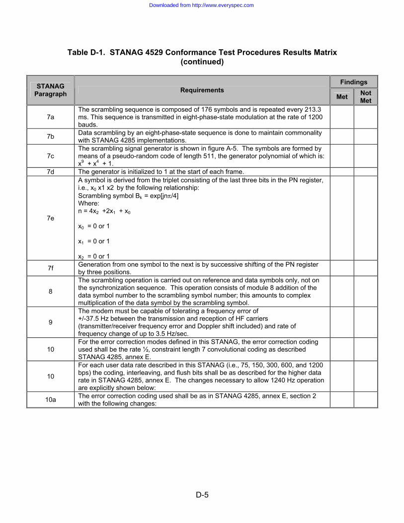
D-5
Table D-1. STANAG 4529 Conformance Test Procedures Results Matrix (continued)
Findings STANAG
Paragraph Requirements Met Not
Met
7a The scrambling sequence is composed of 176 symbols and is repeated every 213.3 ms. This sequence is transmitted in eight-phase-state modulation at the rate of 1200 bauds.
7b Data scrambling by an eight-phase-state sequence is done to maintain commonality with STANAG 4285 implementations.
7c The scrambling signal generator is shown in figure A-5. The symbols are formed by means of a pseudo-random code of length 511, the generator polynomial of which is: x9 + x4 + 1.
7d The generator is initialized to 1 at the start of each frame.
7e
A symbol is derived from the triplet consisting of the last three bits in the PN register, i.e., x0 x1 x2 by the following relationship: Scrambling symbol Bk = exp[jnπ/4] Where: n = 4x2 +2x1 + x0
x0 = 0 or 1 x1 = 0 or 1 x2 = 0 or 1
7f Generation from one symbol to the next is by successive shifting of the PN register by three positions.
8
The scrambling operation is carried out on reference and data symbols only, not on the synchronization sequence. This operation consists of module 8 addition of the data symbol number to the scrambling symbol number; this amounts to complex multiplication of the data symbol by the scrambling symbol.
9
The modem must be capable of tolerating a frequency error of +/-37.5 Hz between the transmission and reception of HF carriers (transmitter/receiver frequency error and Doppler shift included) and rate of frequency change of up to 3.5 Hz/sec.
10 For the error correction modes defined in this STANAG, the error correction coding used shall be the rate ½, constraint length 7 convolutional coding as described STANAG 4285, annex E.
10
For each user data rate described in this STANAG (i.e., 75, 150, 300, 600, and 1200 bps) the coding, interleaving, and flush bits shall be as described for the higher data rate in STANAG 4285, annex E. The changes necessary to allow 1240 Hz operation are explicitly shown below:
10a The error correction coding used shall be as in STANAG 4285, annex E, section 2 with the following changes:
Downloaded from http://www.everyspec.com

D-6
Table D-1. STANAG 4529 Conformance Test Procedures Results Matrix (continued)
Findings STANAG
Paragraph Requirements Met Not
Met
10b
The interleaving shall be as described in STANAG 4285, annex E, section 3 with the following different parameters: Number of rows: I = 32 for all data rates Delay increment “j” for each successive row: Total Interleaving Delay: Data rates 20.48 sec 1.706 sec 1200 bps 48 4 600 bps 24 2 300, 150 and 75 bps 12 1
10c Interleaver synchronization shall be as described in STANAG 4285, annex E, part 4 with no changes.
10d
The initialization and message protocol for use with coding and interleaving shall be as described in STANAG 4285, annex E, part 5 with the following difference: The number of flush zeros for each of the data rates and the two interleaver lengths are as follows: Interleaver Delay Data rate 20.48 sec 1.706 sec 1200 bps 24678 2150 600 bps 12390 1126 300 bps 6246 614 150 bps 3174 358 75 bps 1638 230
11 - Modems shall provide uncoded data transmission modes, in which the coding, interleaving, and associated initialization and message protocols (described in section 10) are not applied to the data transmitted.
11 - Uncoded data modes shall retain all other characteristics described in this STANAG.
11 - Uncoded data rates of 600, 1200, and 1800 bps shall be provided. Legend: bps – bits per second; HF – High Frequency; Hz – hertz; ms—millisecond; PSK—Phase Shift Keying; PN—Pseudo-random Numerical; sec—second; STANAG – Standardization Agreement
Downloaded from http://www.everyspec.com

E-1
APPENDIX E
REFERENCES
Downloaded from http://www.everyspec.com

E-2
(This page intentionally left blank.)
Downloaded from http://www.everyspec.com

E-3
APPENDIX E
REFERENCES E-1 STANAG 4285, Characteristics of 1200/2400/3600 Bits per Second Single Tone
Modulators/Demodulators for HF Radio Links, 16 February 1989 E-2 STANAG 4203, Technical Standards for Single Channel HF Radio Equipment, 31
May 1988 E-3 STANAG 4481, Minimum Technical Equipment Standards for Naval HF Shore-to-
Ship Broadcast Systems, 18 March 1993
Downloaded from http://www.everyspec.com