A A'~ l 7 NTATION PAGE !a AD -A267 15 :b · NATO STANAG 2895ý and MIL-STD-810E'. b. ... basic hot...
37
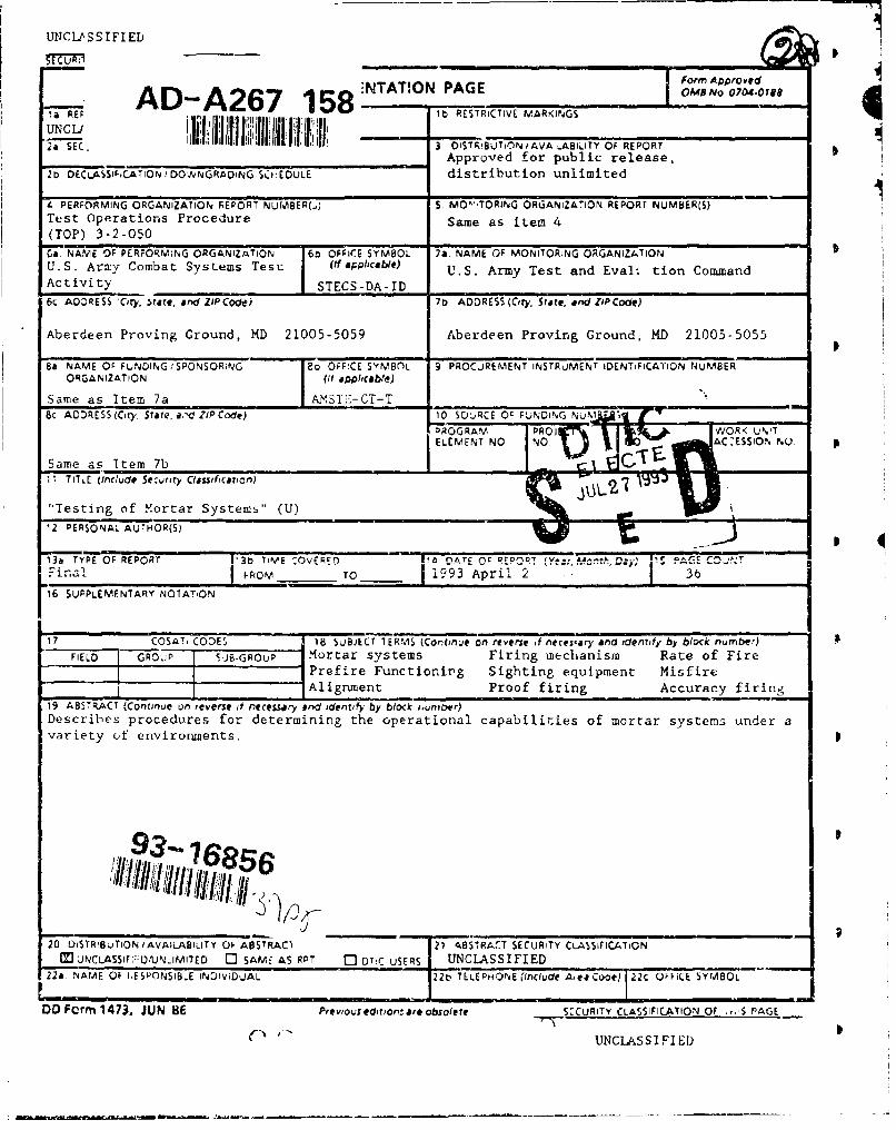
UNCU.SSIFIED A l A'~ 7 NTATION PAGE &Rl07-18 !a REF AD -A267 15 :b RESTRICTIVE MVARKINdGS -2aSEC 3 DiSTR!S~jTi0N i AVA -. ABILITY OF REPORT ____________________________ Approved for public release, 2b DECLA~SI,CATION I DOW,?NGRADNG SCHEDULE distribution unlimited 4 PERFORMING ORGANIZATION REP'ORT NUMBER(.,) S. M0?`'TORING ORGANIZA'ION REPORT NUMBERILS) Te~st operations Procedure Same as item 4 (TOP) 3-2-050 Ca. NAME OF PERFORMiNG ORGANIZATION r6t OFFICE SYMBOL 7a NAME OF MONITORING ORGANIZATION U.S. Army Combat Systems Tesu (if applicable) U.S. Army Test and Evalt tion Command Activity _________ STECS-DA-ID ______________________ 6c. ADDRESS 'City, $rite, and ZIP Code) 7b ADDRESS (City, State, an"ZIP Code) Aberdeen Proving Ground, MD 21005-5059 Aberdeen Proving Ground, KD 21005-5055 So NAME OF FUNDING:'SPONSORifYG TEo OFF!CE SYMB()L 9 PROCUREMENT INSTRuMENT IDENTIFICATION NUMBER ORGANIZATION I (it a.Oriolia6e) Same as Item 7a [AmS T;-,CT-T Bc ADDRESS(City. State, a.'d ZIP Code) 10 SOJRCE OC F-%-DING NU1M -~j PROGRAM PRO VVRKUI Same as Item 7b 1l TITL.E (lnc'ude Sezurity Classifcation,) "iTesting of Mortar Systems" (U) 1 12 PERSONAL AUTHOR(S) r 13a TYPE OF REPORT ['3b TIVE -OVFRF~r) F A nAT C 11:Pr'iOT 1-1 &L-S rl...i Et C r0~ Fin~al FkOM TO i___ 993 April 2 3 I 16 SUPPLEMENTARY NOIAT-ON 17 COSAT. CODES 18 SJBJECT TERMS (Continue on reverse it necescary and identify by block number) FIELD GRO,,;P S*JB-GROuP Mortar systems Firing mechanism Rate of Fire Prefire Functionivg Sighting equipment Misfire IAlignment Proof firing Accuracy firing 19 ABSTRFACT (Continue un rev'erse if necessar-y and identify by block i,unmber) Describes procedures for determining the operational capabilities of mortar systems under a Variety of environments., 93wf 7!68 20 DiT-uINAALB~T FABSTPACT 21 ABSTRAfl SECURITY CLA$SirIC-ATiON M uNCLAssIF;: 2 OANLIMITED [I SAME AS RPT 0 DiTr USERS UNCLASSIFIED 22A NAME OF lýESPONSIBLE INDIViDUAL 220 TEL4EPHONE (Include Aeco Cooe) 22C OFFICE WYM8OL DD Form 1473, JUN 86 Previous edition-, re obsolIete SZCuRiTY CLASSIFICATION Of .- S PAGE C-' UNCLASSIFIED
Transcript of A A'~ l 7 NTATION PAGE !a AD -A267 15 :b · NATO STANAG 2895ý and MIL-STD-810E'. b. ... basic hot...
UNCU.SSIFIED
A l A'~ 7 NTATION PAGE &Rl07-18
!a REF AD -A267 15 :b RESTRICTIVE MVARKINdGS
-2aSEC 3 DiSTR!S~jTi0N i AVA -.ABILITY OF REPORT____________________________ Approved for public release,
2b DECLA~SI,CATION I DOW,?NGRADNG SCHEDULE distribution unlimited
4 PERFORMING ORGANIZATION REP'ORT NUMBER(.,) S. M0?`'TORING ORGANIZA'ION REPORT NUMBERILS)Te~st operations Procedure Same as item 4(TOP) 3-2-050
Ca. NAME OF PERFORMiNG ORGANIZATION r6t OFFICE SYMBOL 7a NAME OF MONITORING ORGANIZATIONU.S. Army Combat Systems Tesu (if applicable) U.S. Army Test and Evalt tion CommandActivity _________ STECS-DA-ID ______________________
6c. ADDRESS 'City, $rite, and ZIP Code) 7b ADDRESS (City, State, an"ZIP Code)
Aberdeen Proving Ground, MD 21005-5059 Aberdeen Proving Ground, KD 21005-5055
So NAME OF FUNDING:'SPONSORifYG TEo OFF!CE SYMB()L 9 PROCUREMENT INSTRuMENT IDENTIFICATION NUMBERORGANIZATION I (it a.Oriolia6e)
Same as Item 7a [AmS T;-,CT-TBc ADDRESS(City. State, a.'d ZIP Code) 10 SOJRCE OC F-%-DING NU1M -~j
PROGRAM PRO VVRKUI
Same as Item 7b1l TITL.E (lnc'ude Sezurity Classifcation,)
"iTesting of Mortar Systems" (U) 112 PERSONAL AUTHOR(S)
r
13a TYPE OF REPORT ['3b TIVE -OVFRF~r) F A nAT C 11:Pr'iOT 1-1 &L-S rl...i Et C r0~Fin~al FkOM TO i___ 993 April 2 3I 16 SUPPLEMENTARY NOIAT-ON
17 COSAT. CODES 18 SJBJECT TERMS (Continue on reverse it necescary and identify by block number)FIELD GRO,,;P S*JB-GROuP Mortar systems Firing mechanism Rate of Fire
Prefire Functionivg Sighting equipment Misfire
IAlignment Proof firing Accuracy firing19 ABSTRFACT (Continue un rev'erse if necessar-y and identify by block i,unmber)Describes procedures for determining the operational capabilities of mortar systems under aVariety of environments.,
93wf 7!68
20 DiT-uINAALB~T FABSTPACT 21 ABSTRAfl SECURITY CLA$SirIC-ATiONM uNCLAssIF;:2OANLIMITED [I SAME AS RPT 0 DiTr USERS UNCLASSIFIED
22A NAME OF lýESPONSIBLE INDIViDUAL 220 TEL4EPHONE (Include Aeco Cooe) 22C OFFICE WYM8OL
DD Form 1473, JUN 86 Previous edition-, re obsolIete SZCuRiTY CLASSIFICATION Of .- S PAGE
C-' UNCLASSIFIED

U.S. ARMY TEST AND EVALUATION COMMANDTEST OPERATIONS PROCEDURE
AMSTE-RP-702-103*Test Operations Procedure (TOP) 3-2-050AD No. 2 April 1993
TESTING OF MORTAR SYSTEMS
Paragraph 1. SCOPE ............. ....................... . .. 12. FACILITIES AND INSTRUMENTATION ...... .......... 23. REQUIRED TEST CONDITIONS .......... ............. 34. TEST PROCEDURES ................ ................. 54.1 Prefiring Functioning and Alignment Tests CZ.....4.2 Ambient Temperature Firing Tests ... ......... .. 114.3 Aderse Conditions Tests .... ............. ... 224.4 Rough-Handling and Transportation Tests ...... .. 284.5 Post Firing Inspections ..... .............. ... 304.6 Human Factors Engineering Demonstration ...... .. 314.7 Tools and Accessories Evaluation ...... ......... 315. PRESENTATION OF DATA ...... ............... ... 31
Appendix A. BACKGROUND .......... .................... A 1B. REFERENCES ............ .................... ... B-1
1. SCOPE.
..is TOP dc.crib. s procedures for Leitteiduu the operationalcapabilities of mortar systems in a variety of environments, the effects oftransport on mortar components, and human factors and maintenance concerns.Mortar systems characteristics dependent upon ammunition t)pe, such asrate-of-fire tests, are also considered. Background information is presentedin Appendix A.
Amaunition-specific tests, such as cook-off and blast overpressure andnoise, have been eliminated from this document as they are better addressedunder safety testing of mortar ammurn.tion (TOP 4-2-504(3)a").
Accesion For
IC Q . ". . ,I . . NTIS CRA&IVTIC TABUnannounced 0J1dstificaton........... ..
B y .... . . .... . . . . .
Dist ibution I
Availability Cudes*This TOP supersedes MTP 3-2-050 dated 18 June 1970. Avail and !or
Dist Special**Supersc.ript numbers/letter correspond to those in Appendix B.
Approved for public release; distribution unlimited.
S I' it • '.I' ,_•"• " .- : )' -'-i• -4.- •' :•'11• ' If,'l •'- ll q, t -•.•..•t -,t - t "-:P il -- I - N .. . , i "r': "• I,, ' I

TOP 3-2-0502 April 1993
2. FACILITIES AND INSTRUMENTATION.
2.1 FiaiUsA.
Item Reguirement
Firing range SAected to suit test requirementsand to provide adequate prot',ctionfor personnel and equipment in eventof ammunition and/or weapon failure.
Temperature conditioning To condition items to temperatureschamber from 71 0C to -51 0C ±2 °C, with
relative humidities ranging from5% to 95%.
Environmental chambers To maintain environments asrequired for adverse conditionstesting.
Non-destructive test facilities To detect and evaluate surface or(magnetic particle, X-ray) subsurface discontinuities (i.e.,
material soundness).
Vibration test facility As required.4. W X A. e. U VJ.
Rough-handling facilities As required.(guidance in ITOP 4-2-6022)
Test courses As required.
2.2 Instrumentatoio.
Permissible ErrorDevices for Measuring" of MeasurfnDevicer
Projectile muzzle velocities +0.1% or +0.5 m/s(guidance in ITOP 4 -2- 8 0 5 b) (whichever is higher)
Weapon chamber pressure +2%(guidance in ITOP 3-2-8101)
Time of interior ballistic event ±3%(guidance in ITOP 3-2-810)
Test item temperature As required.(guidance in TOP 1 - 1 -0 5 8 d)
Physical charactertstics of test item As required.(guidance in MTP 3-2-801", ITOP 3 -2-803f)
2

TOP 3-2-0502 April 1993
Permissible Error
eic pr_•_e U4ingifl~i of Masuring Device:
Aeteoroi.ogicr& conditions (guidance As required.in TOP 3-1-0039)
lest events (e.g., video tape, 35-mm As required.
camera)
3.1
. The rests as describel in this TOP are used to determine safety,peiforuanc-, end reliabil4ty charsctezistics of the weapon system in question.Plan tie ordex of resting to allow the safety-evaluation tests (para 4.2.1) toN.e conc cced first. Conduct '-igh-risk tests which will reveal designw. Pknerses immediately followlug the safety tests.
b. Take care in planning the test sequence. Two or more subtests may benibined so long as no test criteria or objectives are jeopardized. Certain
.sts way be c'one concurrently, while other tests (such as sustained rate-of-fire and maximum rperating temperature tests) can be &dne sequentially to takeadvantage of existing mortar temperatures to eliminate the need for expendingaddijiua. toutilds if ubliib U4&rr'l h&LCUL- ,v 1.- 6iL-Lt' upeiaLdttg tewperatuie
of the mortar. Use inert projectiles and ammunition during firing tests ifthe use of such ammunition will not compromise test results.
c. The test procedures described herein may be required in a detailedtest plan. The procedures may require modification for unique items ormaterials or to satisfy specific testing requirements as stated in themateriel developer's test plan or the Independent Evaluation Plan/Test DesignPlan (TEP/TDP) or the Independent Assessment Plan (lAP).
3.2 Test Preparation.
3.2.1 ixLiue Temperature Limits.
a. Unless otherwise specified, conduct mortar-system tests at a lower-extreme-temperature of -46 OC, which corresponds to the cold category C2 ofNATO STANAG 2895ý and MIL-STD-810E'.
b. Conduct upper-extreme-temperature tests at 63 0C corresponding to thebasic hot climatic category A2 of NATO STANAG 2895 and MIL-STD-810E.
3
haLt, j ji a .l- .~ --
4TOP 3-3-050
2 April 1993
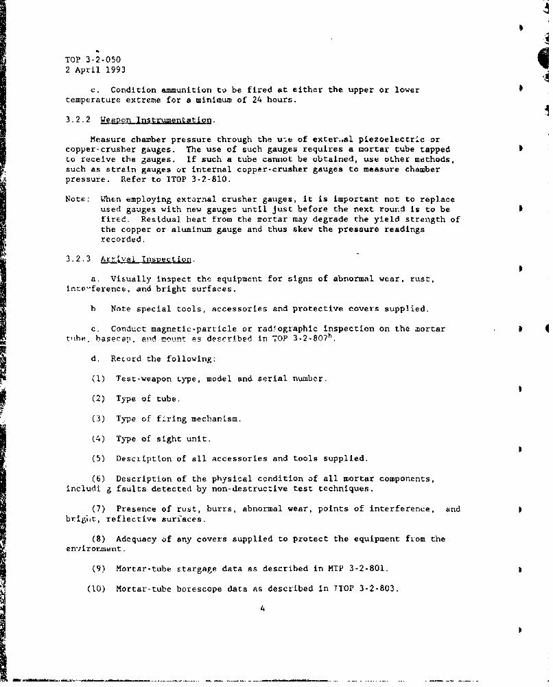
c. Condition ammunition to be fired at either the upper or lowertemperature extreme for a minimum of 24 hours.
3.2.2 Weapon Instrumentation.
Measure chamber pressure through the use of exter.,al piezoelectric orcopper-crusher gauges. The use of such gauges requires a mortar tube tappedto receive the gauges. If such a tube cannot be obtained, use other methods,such as strain gauges or internal copper-crusher gauges to measure chamberpressure. Refer to ITOP 3-2-810.
Note: When employing external crusher gauges, it is important not to replaceused gauges with new gauges until just before the next round is to befired. Restdual heat from the mortar may degrade the yield strength ofthe copper or aluminum gauge and thus skew the pressure readingsrecorded.
3.2.3 Arrival Inspection.
a. Visually inspect the equipment for signs of abnormal wear, rust,inte'-ference, and bright surfaces.
b Note special tools, accessories and protective covers supplied.
c. Conduct magnetic-particle or radfographic inspection on the mortar 4t-iibe hanprrT' and mount ns describhe in 70P 3 -7- 8 0 7 h.
d. Record the following:
(1) Test-weapon type, model and serial number.
(2) Type of tube.(3) Type of firing mechanLsm.
(4) Type of sight unit.
(5) Desctiptton of all accessories and tools supplied.
(6) Description of the physical condition of all mortar components,includi g faults detected by non-destructive test techniques.
(7) Presence of rust, burrs, abnormal wear, points of interference, andbrig7ht, reflective surfaces.
(8) Adequacy of any covers supplied to protect the equipment from theen-iirornment.
(9) Mortar-tube stargage data as described in MTP 3-2-801.
(10) Mortar-tube borescope data as described in TIOP 3-2-803.
4

TOP 3-2-0502 April 1993
(11) Length of firing-pin protrusion. b
3.2.4 Physical 9haracteristics.
a. Determine the total weight of the test item and mount components.
b. Prepare the item for hand carrying as de.•cribed in the appropriatefield or technical manual and note the number, weights ai~d description ofloads into which the mortar unit can be disassembled.
c. Prepare the item for transport on either a towed cart or as part of amortar carrier, and note the weight at each wheel, total weight, lunettereaction at pintle height, and height of lunette when reaction is zzro.
d. Prepare the item for firing as described in the appropriate fieldmanual.
e. Photograph the test item as set up in paragraphsb, c, Liid d a.ove,paying particular attention tc any unusual iesign features.
f. Determine types of rounds to be fired from mortar during test and allother compatible munitions.
3.2.5 Characteristic Data Shee.
Prepare- a Characteristics Dats Sheet 1AW TOP 3-2-5005 non'•titng of Agenerdl-view phocograph of the weapon and a listing of principal physical andperformance characteristics.
4. TEST PROCEDURES.
4.1 Prefire Functioning a!..dAlignmec.L Tests.
Determine the smoothness of operation and physical aligrnenr of the majorcomponents and of the assembled test item as follcws:
4.1.1.1 ehd
a. Visually examine the interior condition of the tube and, whenapplicable, the threads on the breech end of the tube.
b. Determine the ease of alignrient, assembly and disassembly of theindividual mortar-tube sections.
c. Determine the nsed for quadrant seats on the tube or on theclamp.
5

TOP 3-2-050
2 April 1993
4.1.1.2 2ata reuire.
a. Interior COL Aition of tube.
b. Ease of alignment, assembly and disassembly of tube sections.
c. Need for quadrant seats on the tube or the clamp.
4.1I. 2 Basecaip - Fixed U-1109 R11.
4.1.2.1 kt .
a. Remove the basecap from t'he trbe.
b. Perform required measurements.
c. Replace basecap onto tube.
4.1.2.2 Data required.
a. Ease of disassembly of the basecap from the tube when not brazed.
b. Ease of replacement of firing pin.
c. Length of firing pin protrusion.
d. Concentricity of firing pin hole and ba-ccap tube threads.
e. Ease of basecap assembly.
f. Conforma.'ce of component axes to specifications.
4.1.3 .aseca. Sr~lectable firing me" n alsm.
4.1.3.1 M[eh.
a. Operate firing mechanism switch (and trigger, if app]i~.l-:0).
b. Disassemble firing mechanism.
c. Perform requrxecd measurements.
d. Reassemble firing mechanism.
4.1.3.2 Datg .5, uirgdhj.
a. Method of functioning.
b. Ease of seiecting the different types of firing.
c. Interference between firing lever and baseplate.
6

TOP 3-2-050
2 April 1993
d. Ease of assembly and disassembly. 0
C Smoothness of operation.
f. Confotmance to specifications.
4.1.4 a k_&bs er1. .
4.1.4.1 .thod.
Note: If the mortar has a recoil system, obtain the characteristics of therecoil portion of the mount as described in the applicable sections of1.CP 3-2-815'.
a. Manually exercise shock mechanism.
b. Disassemble shock absorber mechanism and inspect components.
c. Reassemble mechanism.
4.1.4.2 Dqu xrAir.
a. Ease of assembly and disassembly of shock absorber mechanism.
b. Types and adequacy of- lubricants. 0
c. Adequacy of moisture-proofing.
d. Adequacy of operation.
Note: Manually pull the shock absorber out of battery and allow it to returnto in-battery position. If it fails to return or returns very slowly,check the alignment of the moving parts with their housing and verifythe adequacy of provisions for the escape of trapped air.
4.1.5 Eleva•nad Traversin& Mechanisms.
4.1.5.1 1lhod.
a. Elevate and traverse weapon through the entire range of movementusing Loth coarse and fine adjustments.
b. Disassemble both mechanisws.
4.1.5.2 Data reguire.
a. Ease of assembly and disassembly.
b. Smoothness of gear operation in elevation and traverse.
c. Amount of gear backlash in both elevation and traverse.
7

TOP 3-2-0502 April 1993
d. Amount of handwheel effort required throughout the entire elevationand traverse.
e. Number of handwheel turns per degree of movement in elevation and intraverse.
f. Movement limits:
(1) Maximum and minimum elevation.
(2) Maximum and minimum traverse.
g. Safety hazards and incLnveniences caused by handwheel location,taking into account the possibility of interference between the operator'shand and the tube support of the trave se yoke.
4.1.6 Mortar Clemp.
4.1.6.1 Method.
a. Unlock clamp and remove tube from constraint.
b. Reclamp tube.
4.1.6.2 Data required.
a. Ease of fastening and locking the clamp to the mortar.
b. Clamp slippage.
4.1.7 Cross-Leveling Mechani.sm.
4.17.1 Method. Use cross-leveling mechanism to remove induced-cant fromweapon.
4.1.7.2 Data ýuired.
a Smoothness of operation using the coarse and fine adjustments of thecross-leveling mechanism.
b. Ease of operation, determined while observing the level vial in thetraverse yoke end checking the freedom of movement of the leveling mechanism.:hen in the unclamped position.
c. Locking ability of clamp(s).
4.1.8 TelescoDically-Adiusted.AIod Legs_(if applicable).
4.1.8.1 Metho. Adjust legs to minimum and maximum length.
8

TOP 3-2-0502 April 1993
4.1.8.2 Data ieguired.
a. Freedom of movement.
b. Locking ability of clamps.
4.1.9 Bridge and Standard (if applicable).
4.1.9.1 M .
a. Without moving the elevating and traversing mechanisms, shake tubeand exercise recoil system.
b. Elevate and traverse mortar through range of movement.
4.1.9.2 Data required.
a. Fit of lugs with the trunnions in the bridge.
b. Ability of tube to rcturn to original position after beingtemporarily displaced.
c. Operation of traversing and elevating mechanisms in the standard.
4.1.10 o
4.1.10.1 =thoQ.
a. Insert and remove tube from baseplate.
b. Determine adequacy of provisions for hand-carrying baseplate.
4.1.10.2 Data Reouired.
a. Fit of ball on mortar basecap into baseplate socket.
b. Ease of assembly and disassembly, if applicable.
c. Method of locking baseplate latches, if applicable.
d. Adequacy of carrying handles.
4.1.11 Sikhting EquiDment.
4.1.11.1 e
a. Affix sight unit (and/or boresight) to mortar.
b. Use sighting equipment to lay-in mortar.
9

TOP 3-2-0502 April 1993
4.1.11.2Daargi.d
a. Ease ot operation of sighting equipment.
b. Accuracy of sight-alignment (i.e., deviation from ,n establishedazimuth, compared with surveyor's transit).
c. Ease of alignment to the line of sight, checked with a mortarboresight.
d. Vial(s) adjustment ease.
e. Damage susceptibility,
f. Adequacy of the provision for stowing and carrying sightingequipment.
g. Adequacy of tools.
h. Adequacy of instructions.
i. Interference of sight controls with mount parts.
4.1.12 hortar (Assembled).
4.1.12.1 Metho
a. Move the test item from the travelir.g position to the firing positionand back to the traveling position; record data IAW 4.1.12.1 below. This taskshould be repeated three times with different test personnel.
b. Mark components subject to severe strain with trammel points orstraightness lines.
c. Mount strain gages as described in TOP 3-1-006i or cover the surface
of areas subject to s rain with brittle lacquer as described in TOP 3 -2- 8 0 9 k.
4.1.12.2 Data reQuired.
a. Time required to prepare weapon for firing.
b. Time required to prepare weapon for travel.
c. Difficulties encountered in preparation for firing and travel.
d. Number of personnel required to prepare the weapon for firing and
cravel.
e. Adequacy of instructions.
f. Adequacy of supplied tools.
10

4
TOP 3-2-0502 April 1993
g. Need for system-unique tools or whether common, off-the-shelf toolsare adequate.
4.2 Ambient Temoerature FirLng Tests.
Note: Use inert-loaded projectiles and inert fuzes during the firing testswhen the substitution will allow the test objectives to beaccomplished.
4.2.1 Safety Evaluation Test.
The safety evaluation of a new weapor design requires the following teststo be conducted.
a. Proof firing of the weapon as described in paragraph 4.2.2.
b. Establishment of the maximiun mortar temperature resulting fromsustained fire, as described in paragraph 4.2.3.3.
c. Verification of weapon-system operational capability ac maximumoperating temperature as described in paragraph 4.2.4.
4.2.2 .roof-Fir,__-.•.
4.2.2.1 H d.
Note: Proot-fire any mortar to be fired for test purposes to discloseany deficiency or malfunction that would preclude its furtheruse. Under no circumstances shall it be used with personnelexposed until after proofing has been completed.
Perform proof-firing tests at prevailing ambient temperatures with thetypes and number of rounds specified in the materiel developer's test plan,IEP/TDP, or IAP. If a firing schedule was not provided, fire the rounds, insequence, at the positions of elevati3n and traverse shown in Table 1.
TABLE 1. PROOF-FIRING SCHEDULE
Percent of Upper Elevation_ No. of L •,,ods Pressure Limit* (deg) Traverse
Seating Rounds 50-75 60 Center(approx 5)
1 75 60 Center1 100 45 Max right
iiI

TOP 3-2-050
2 April 1993
TABLE 1 (CONT'D)
Percent of Upper ElevationNo.of Rounds Pressure liiLt* .. Cde.ig. Traverse
1 113 + 4 45 Center1 100 45 Max right1 113 + 4 60 Center
"The upper pressure limit (UPL) should be provided by the developer. When
the UPL is not known, use pressure values for mortars of a similar construc-tion as a starting point.
4.2.2.2 Data re-. kred.
a. Type and condition of soil under the baseplate in terms of moisture-intent and Cone-Penetrometer Index using a cone penetrometer in conjunctionwith a soil sampler and remolding test equipment as described in TB ENG 37Soi'c Trafficability'.
I'. Number of rounds required to seat :he \aseplate.
c. For each round fired after the baseplate has been seated:
(1) Chamber pressure as described in ITOP 3-2-810.
(2) Muzzle veloc'.ties as described in ITOP 4-2-805.
(3) Length of out-of-battery movement of shock absorber.
(4) Change in elevation and traverse of mortar.
(5) Amo..,, of muzzle smoke and flash.
d. Incurred strain as described in TOP 3-2-809.
e. During and at completion of proof firing, the following asapplicable:
(1) Eraaks, cracks (note welded portions), deformations, and binding ofthc working part.. of the mortar and mount, photographing a.iy failures.
(2) Interference between the operating parts at all possible pocitionsof elevation and traverse.
(3) Ability of shock absorbers to return to the in-battery position at
various positions of the collar and tube support.
12
I

TOP 3-2-050
2 April 1993
(4) Gas leakage at juncture of mortar tubes and basecap.
(5) Gas leakage between firing pin and its contazt surface in thebasecap.
(6) Gas leakage at juncture of sectional tube'
(7) Slippage of mount collar on the mortar tube
(8) Slippage or turning of bipod legs or standard.
(9) Slippage of leveling mechanism.
(10) Possibility of firing without firing pin or with retracted firingpin.
(11) Ease of loading.
(12) Completeness of propellant burn within mortar tube.
(13) Ability of on-carriage fire-control equipment to remain locked inposition duriig firing and to retain boresight alignment
(14) Malfunctioning of ammunition (misfires and hangfires).
(15) yTni,.iia! occurrencesc affecting crew safety.
4.2.2.3 Eost proof-firing inspection.
4.2.2.3.1 Method. Upon completion of the procf firing, perform thefollowing:
a. Note effort required to turn handwheel.
b. Compare trawrel-point positions on the mount with originalpositions.
c. Measure firing-pin protrusion and note any deformation.
d. Examine all moving parts and note evidence of wear or scoring.
e. Stargage the test item.
f. Borescope the test item.
g. Remove strain gages, if applicable.
h. Use appropriate non-destructive test technique (radiographic,magnaflx, etc.) to determine presence of cracks, deformations, etc., onmortar tube, basecap and baseplate.
13

TOP 3-2-0502 Ayril 1993
4.2.2.3.2 Data rtmired.
a. Stargage data.
b. Borescope data.
c. Effort required to turn handwheel.
d. Change in trammel-point positions relative to original position.
e. Firing-pin protrusion measurements.
f. Evidence of wear or scoring.
4.2.3 Rapid-Fire Tests.
Notes: Maximu,- ph'. ical rate of fire is described as tie maximum rateat which it is physically possible to fire the weapon, limitedby time and temperature constraints.
Sustained rate of firr is defined as the rate of fire, for aparticular charge and ammunition type, at which the test weaponcan be continuously fired without exceeding the barrel'sdesignated maximum operating temperature (D-MOT).
4.2.3.1 T.st preparation. 0 4
a. Adapt and install an electric timer to measure the time required fora projectile to slide down the tube and strike the bottom.
b. Affix thermocouples to points along the tube where maximumtemperatures may be expected, or as directed in the test plan. 0
Note: Affix thermocouples to the tube so as not to alter the physicalproperties of the tube.
c. Place the test item on soil similar to the soil on which the prooffiring was conducted and fire a minimum of five rounds to seat the test item. 0
4.2.3.2 M-jxlmum rate-of-fire test.
4.2.3.2.1 Method..
a. Have one member of the test team fire the weapon at a specific 0
elevation (minimum, intermediate, or maximu:) u3ing its maximum servicecharge, as fast as possible for a specified time period or until the tubetemperature reaches the D-MOT.
b. Record data as indicated in paragraph 4.2.3.2.2 below.
14
tP

p
TOP 3-2-0502 April 1993
pc. Repeat this procedure a minimum of three times at each elevation,
using different personnel for each repetition.
4.2.3.2.2 Data reauired.
a. Time of dascent of the cartridge at minimum, intermediate, andmaximum elevations.
b. For each team member at a specified elevation:
(1) Time required to fire each round.
(2) Number of rounds fired.
(3) Time to reach D-MOT.
(4) Maximum rate-of-fire (number of rounds fired/time to reachD-MOT). Expressed aq number of rounds per minute for X minutes.
(5) Effects of blast, smokc, and flash on visibility, operation offire-control equipment, and on firing team members.
4.2.3.3 Sustained-Rate-of-Fire Test.
4.2.3.3.1 Method.
a. Note temperature of tube, before firing, at all locations.
b. Heat the mortar tube with a barrel heater until a temperatureapproximately 30 OC below the D-MOT is reached. Immediately following thisphase, remove the barrel heater and rapidly fire as many maximum-service-charge rounds as is necessary to bring the tube temperature to the D-MOT.
c. Alter the rate of fire so that the tube temperature is maintainedconstant at the D-MOT.
d. Note the rate of fire at which the tube temperature is stabilized at
the D-MOT.
e. Repeat steps a through d for all applicable charges.
4-2.3.3.2 Data required.
a. Temperature of mortar tube at all instrumented locations.
b. Sustained rate of fire for all applicable charge levels.
15
15
p

TOP 3-1-0502 April 1993
4.2.4 Maximum Operating Temperature Test.
] L,.2.4. ti ethod.
a. Heat the mortar tube with a barrel heater until a temperatureapproximately 30 0C below the D-MOT is reached. Immediately following thisphase, remove the barrel heater and rapidly fire as many maximum servicecharge rounds as is necessary to bring the tube temperature to the D-MOT.
b. When the maximum operating temperature is reached, immediately fire200 maximum-service-charge rounds (conditioned at 63 %C for 24 hours) at arate which mo<ntains the tube temperature at the D-MOT.
c. Note che time at which each round is fired.
d. After all firing has been completed, visually inspect the mortarsystem.
e. When the system has returned to ambient temperature, stargage themortar tube. Test the tube, mount and baseplate for material soundness.Record operability ui all mechanisms; note effort to turn handwheels.
4.2.4.2 Data required.
a. Tube temperature throughout firing and for 15 minutfq followingfiring.
jb. Time at which each round was fired.
c. Weapon-bore dimensions before and after firing.
d. Operability of all we-•.-nisms, and the effort required to turn thehandwheels.
e. Material-soundness-test results bef-re and after firing.
4.2.5 Misfire Removal Test.
4.2.5.1 McthoJ.
To determine whether additional safety procedures are necessary in
removing misfires from the test mortar, have all gun crew members help toremove a simulated misfire from the test mortar. Accomplish the misfireremoval while operating within safety rtgulations. Rotate positions of crewmembers until each has served in every position.
4.2.5.2 iDtaelic .
a. Ease and safety ot round removal.
I 16
TOP 3-2-0502 April 1993
b. Recommendations for modifying removal technique, if appropriate.
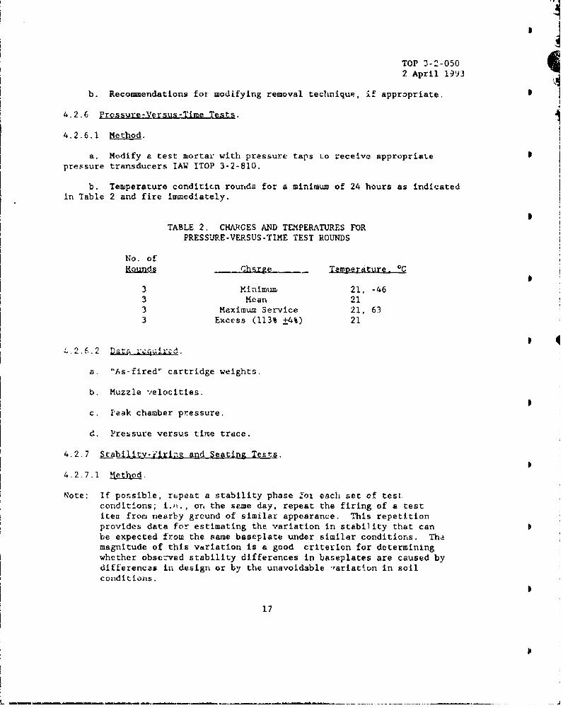
4.2.6 Pressure-Vgrsus-Time Tests.
4.2.6.1 Method.
a. Modify a test mortar with pressure taps t:o receive appropriatepressure transducers IAW ITOP 3-2-810.
b. Temperature conditicn rounds for a minimum of 24 hours as indicatedin Table 2 and fire immediately.
TABLE 2. CHARGES AND TLMPERATURES FORPRESSURE-VERSUS-TIME TEST ROUNDS
No. ofRo... Charge _ TempelAture. *C
3 Minimunm 21, -463 Mean 213 Maximum Service 21, 633 Excess (113% ±4%) 21
a. "bs-fired" cartridge weights.
b. Muzzle velocities.
c. Peak chamber pressure.
d. Pressure versus tiile trace.
4.2.7 iLgbility-r'irin and Seating Tests.
4-2.7.1 Jethod.
Note: If possible, repeat a stability phase .or each set of testconditions; i.e., on the same day, repeat the firing of a testitea fror nearby ground of similar appearance. This repetitionprovides data for estimating the variation in stability that canbe expected from the same baseplate under similar conditions. Thamagnitude of this variation is a good criterion for determiningwhether observed stability differences in baseplates are caused bydifferences in design or by the unavoidable -ariation in soilconditions.
17

TOP 3-2-0502 April 1993
Determine the stability of the mortar and baseplate and the ease ofseating in both prepared and unprepared positions, as follows. Video-tape allfirings for later review.
a. Determine and record the type of soil upon which the weapon ispositioned as described in paragraph 4.2.2.2a.
b. With sandbags appropriately positioned on the baseplate, conduct the 0
firing as shown in Table 3, re-laying the mortar after each single round andeach group firing.
TABLE 3- STABILITY FIRING SCHEDULE
Number of Rounds Elevation. deg Traverse
Seating rounds 60 Center(approximately 5)
2 individual rounds Maximum Centerand one 5-round group Maximum Max ieftat each elevation/tra- Maximum Max rightverse combination 60 Centershown. 60 Max left
60 Max right
Minimum CenterMinimum Max leftMinimum Max right
Note: All rounds are fired at maximum service charge.
c. Record data as directed in paragraph 4.2.7.2g below.
d. Repeat steps a and b without using sandbags.
e. Repeat steps a through c without relaying the. weapon.
f. Rep~eat steps a through d with the weapon on:
(1) Sand.
(2) Mud.
(3) Very-hard ground.
g. Repedt all steps with weapon in an unprepared position.
18

TOP 3-2-0502 April 1993
4.2.7.2 Date reguired.
a. TYpe of soil.
b. Seating adequacy on unprepared soil.
c. ¶he nec~ssity for field expedient•.
d. Preparations made to the positions.
e. Fumber of rounds required for each seating.
f. Comments as to the ease or difficulty experienced in seating theweapon.
g. After thA baseate is firmly seated, record the following for eachrournd or group of rounds fired.
(1) Change in elevation and deflection.
(2) Number of centimeteis the baseplate:
(a) Moved downward.
(b) Moved to the rear. -
(c) Tilted side-to-side and front-to-rear.
4.2.8 Hard 5urface Firing Tests.
4.2.8.1 Method.
Note: This test gives an indication of how the system may perform when firedfrom ice and snow surfaces.
a. Position the test weapon ci a macadam or concrete surfact withoutfield expedients and conduct the firing as sho6-n in Table 4. Record the typeof surface used.
19

TOP 3-2-0502 April 1993
TABLE, 4. HARD SURFACE FIRING SEQUENCE
No. of Rounds Elevation. degTraer
Seating rounds 60 Center(approximately 5)
5 Maximum Max left5 Maximum Max right5 60 Max left5 60 Max right5 Minimum Max left5 Minimum Max right5 Minimum Center
Note: All rounds are fired at maximum service charge.
b. Examine che mortar after each round and record data as directed in
paragraph 4.2.8.2 below.
c. Photograph or film any defects or hazardous occurrences.
d. Repeat steps a through c using field expedients.
e. Repeat steps a through d with the weapon on a rocky surface.
4.2.8.2 Data required.
8. Location of any breaks, cracks, etc.
b. Comporent faiiures.
c. Ability of mortar to seat and remain seated.
d. Incidents that may affect crew safety.
4.2.9 Accuracy Firing,.
4.2.9.1 Method.
Notes: Weapon accuracy or system accuracy can be determined. Determineweapon accuracy by use of the gunner's quadrant for elevation andthe surveyor's transit for azimuth; determine system accuracy byusing the system sight unit for mortar laying.
Standard ammunition should be used for this test. If developmentalammunition is used, it's contribution to system error will beunknown unless groups from several lots are fired.
20

TOP 3-2-0502 April 1993
Determire the test item accuracy, using criteria as specified in themateriel developer's test plan, IEP/TDP, or IAP, as follows:
a. Firmly seat the test item and record the soil type.
b. Measure and record the meteorological data, as required inparagraph 4.2.9.2, on an hourly basis throughout the test period.
Notes: Commence measurements just prior to the start of the testfiring.
Take me&surements at ground level at the location of the testitem and at the anticipated point of impact.
Take aloft data at intervals up to and including the maximumordinate of the round to be fired.
c. Fire at least ten minimum charge rounds with the test item at zerotraverse and minimum elevation.Note: Return the test item to its prefiring position after each round is
fired.
d. Repeat step c for each charge appropriate for the test item.
e. Repeat steps c and d with the test item at mean elevation and maximumelevation.
4.2.9.2 Data required.
a. On an hourly basis throughout the test period:
(1) Ambient temperature.
(2) Relative humidity.
(3) Atmospheric pressure.
(4) Wind speed and direction.
b. For each round fired:
(1) Muzzle velocity as described in ITOP 4-2-805.
(2) Time of flight as described in ITOP 4-2-805.
(3) Changes in elevation, if applicable.
(4) Changes in traverse, if applicable.
(5) Distance and direction the baseplate moved, if applicable.
21
j6I
TOP 3-2-0502 April 1993
c. Horizontal range and deflection of the impact of each fired round. I
d. Maximum range recorded during firing at maximum-service-chargc and
minimux1 elevation.
e. Minimum range recorded during firin& at charge zero and maximumelevation.
4.3 Adverse-Conditions Tests.
4.3.1 Preopration for Tests.
a. Clean the test item and apply a light coat of lubricant to theoperating mechanisms.
b. Mount the test-item sight and accessories.
c. Cover the muzzle with the protective muzzle cover, if provided.
d. Note handwheel effort prior to subjecting test item to each adverseenvironment test.
4.3.2 Extreme Tlemerature Tests.
4.3.2.1 Method. 4
a. Using an appropriate climatic-conditioning chamber, set u1 the weaponsystem (including sight-unit) in the firing position and condition for 48hours at -46 'C.
b. After conditioning, fire one maximum-service-charge round(conditioned at 21 *C) and visually examine the weapon system for damage.
c. If no damage is found, repeat the process until ten maximum-service-charge rounds have been fired with the system allowed to return to -46 °Cbetween rounds.
d. Immediately after firing, conduct material-soundness inspections ofthe veapon and components to determine the presence of cracks (TOP 3-2-807).
e. Photograph all defects.
f. Record handwheel efforts before and after firing at a specifiedmortar position for comparisen with the effort noted during the prefiringcheck.
g. Examine the sight-unit for operability, including presence ofmoisture inside the telescope; note the operability of all sight knobs.
22
!I

TOP 3-2-0502 April 1993
h. Repeat test with mortar conditioned for 48 hours at 63 0C.
4.3.2.2 Data reouired.
a. Interferences or malfunctions of mechanisms and moving parts inducedby temperature extreme.
b. Functioning of firin, mechanism (applicable if trigger or retracting-firing-pin components are used).
c. Positiveness of action of the firing mechanism.
d. Functioning of shock-absorber assembly.
e. Shock absorber's resistz:-.-.. to cracking at low temperatures.
f. Handwheel efforts.
g. Material-soundness-test results.
h. Operability of sight unit.
4.3.3 Sand-and-Dust Test.
4.3.3.1 Method.
a. Prepare the test item as described in paragraph 4.3.1.
b. Expose the test item to the blowing-dust conditions specified inMIL-STD-81OE, Method 510.3.
c. After exposure, remove loose dust (sand) by shaking the test item,V- .ing on it, or wiping it with the bare hands.
d. Check visibility through the sight, and note presence of trappeddust.
e. Elevate and traverse weapon through complete range; note handwheeleffort.
f. Note presence of any trapped dust (sand) in cannon bore.
g. Thoroughly clean weapon system and then repeat above procedures,exposing the weap..n to the blowing-sand test of HIL-STD-810E, Method 510.3.
4.3.3.2 Data required.
a. Presence of dust in s'ght.
23
iI

TOP 3-2-0502 April 1993
b. Oper-jility of the lever-fire mechanism (If applicable) by firing in Ithe lever-fire position and then in the drop-ire position.
c. Ease of lever-fire operation.
d. Handwheel effort required to elevate and traverse test item.
e. Amount of dust in cannon bore.
4.3.4 Icing Test.
4.3.4.1 Method
a. Prepare the test item as described in paragraph 4.3.1.
b. Expose the test item and its components to the freezing-rain test as
described in TOP 2-2-8156.
c. After exposure:
(1) Check visibility through the sight, and note presence of trappedmoisture within the sight.
(2) Attempt to elevate and traverse mortar.I 4
(3) Fire one maximum-service-charge round (conditioned at 21 'C) anuvisually examine the weapon system for damage.
(4) If no damage is found repeat the process until five maximum-service-charge rounds have been fired from the weapon.
(5) Immediately after firing, conduct materiel soundness inspections ofthe weapon and components to determine the presence of cracks.
4.3.4.2 Data reauired.
a. Amount of ice needed to be removed in order to fire the first round.
b. Difficulty in elevating and traversing the test item.
c. Operability of the lever-fire mechanism by firing in the lever-fireposition and then in the drop-fire position.
d. Ease ot lever-tire operation.
e. Effectiveness of ice removal by firing.
24

TOP 3-2-0502 April 1993
4.3.5 B lownrSnow Test.
4.3.5.1 .I
a. Prepare the test item as described in paragraph 4.3.1.
b. Expose the test iteui and its components, in a conditiouiing chamber toblowing bnow having crystal sizes and winds as described in AR 7 0 - 3 8 ' for aperiod of 6 hours.
c. After exposure, remove the loose snow by shaking the test item,blowing on it, or wiping it.
d. Follow procedures as described in paragraph 4.3.4.1c above.
4.3.5.2 Data required. As shown in paragraph 4.3.4.2.
4.3.6 Mud Test.
4.3.6.1 Method.
a. Prepare che test item as described in paragraph 4.3.1.
b. Expose the test item to mud consisting of 10 parts red clay, twoparts clean river sand, and enough water to permit the item to sink of its owlnweight.
c. After exposure, remove loose mud with bare hands.
d. Follow procedures as described in paragraph 4.3.3.1, sections cthrough e, examining the sights for mud.
4.3.6.2 Data required. As specified in paragraph 4.3.3.2.
4.3.7 Rain Test.
4.3.7.1 Method.
a. Prepare tne test item as describ~d in paragraph q.3.1.
b. Expose the test item to the rain conditions described inMIL-STD-810E, Method 506.3.
c. After exposure, examine sights for moisture and evaluate the effectson the moving parts of the mortar.
25
%I

TOP 3-2-9502 April 1993
4.3.7.2 Data required.
a. As specified in TOP 2-2-815 and MIL-STD-81OE.
b. Presence of moisture in sights.
c. Presence of moisture in cannon bore.
d. Handwheel effort required to elevate and traverse weapon.
4.3.8 Humidity Test
4.3.8.1 Mhod.
a. Prepare the test item as described in paragraph 4.3.1.
b. Expose the test item to the applicable conditionf as described inMIL-STD-810E, Method 507.3.
0c. After exposure, examine sights for moisture, check for corrosion, and
evaluate effects on the moving parts of the mortar.
4.3.8.2 Data requIred.
a. As specified in MIL-STD-810E.
b. As specified in paragraphs 4.3.7.2b through d.
4.3.9 Solar Radiation Test.
4.3.9.1 Method.
a. Prepare the test item as described in paragraph 4.3.1.
b. Expose the test item to five diurnal cycles of the hot-dry climate asdescribed in ITOP 4-2-826'.
Ic. After exposure, examine optical and moving parts fcr damage.
4.3.9.2 Data required. Damage to optical and moving parts.
4.3.10 Salt-Fog Test.
4.3.10.1 Mel•.
a. Prepare the test item as described i: paragraph 4.3.1.
b. Expose the test item to salt-fog conditions described inMIL-STD-810E, Method 509.3 for 48 hours.
26
, I I II• iI II

TOP 3-2-0502 April 1993
c. After exposure, examine the sights for moisture, uheck for corrosion,and check operability of all parts.
4.3.10.2 Daareguired.
a. Amount of moisture trapped within the sight.
b. Amount of corrosion.
c. Handwheel effort required to elevate and traverse weapon.
4.3.11. WaLer-Immersion Test.
4.3.11.1 Method.
a. Prepare the test item as described in paragraph 4.3.1.
b. Expose the test item or components to the water-immersion testdescribed in MIL-STD-810E, Method 512.3.
c. After exposure, examine the sights for moisture and check theoperability of all parts.
4.3.11.2 Data required.
As speciiieu in parasrapns .7 rnrougn o.
4.3.12 Fungus Test.
4.3.12.1 Method.
a. Prepare the test item as described in paragraph 4.3.1.
b. Expose the test item tG the conditions described in MIL-STD-810E,Method 508.4.
c. After exposure, examine all components for moisture, fungus, andcorrosion.
4.3.12.2 Data um .
a. Presence of moisture, fungus and corrosion or. weapon system.
b. Operability of sight unit.
c. Handwheel effort required to elevate and traverse weapon.
27

TOP 3!2-0502 April 1993
4.4 Rough-Handlina and Transoortationa•n s.
The mortar shall be tested under the following conditions, as required.
4.4.1 Transportation-Vibration Tes:.
4.4.1.1 M to .
a. Package the test item as for shipment.
b. Conduct a simulated transportation-vibration test in accordance withITOP 1-2-601 corresponding to a distance of 800 kilometers in a composite ofwheeled vehicles and 50 kilometers in two-wheeled trailers.
c. Examine the test item and record the presence of any breakage,bending, loosening, or other damage.
d. When there is no obvious damage, test fire the item using a minimumof five maximum service charge rounds, then examine the test item and recordany evidence of damage.
4.4.1.2 Data Required.
a. Transportation-vibration data as collected in ITOP 1-2-601.
b. Results of materiel inspections as conducted above.
4.4.2 Loose-Cargo Test.
4.4.2.1 Method.
a. Using an unpackaged test item, conduct a loose-cargo test inaccordance with Appendix B of ITOP 4-2-602 to simulate 240 kilometers ofloose-cargo transport over Balgian-block raad.
b. Examine the test item and fire as described in steps c and d ofparagraph 4.4.1.1.
4.4.2.2 Data reouired.
a. As collected in !TOP 4-2-602.
b. Results of materiel inspections as conducted above.
4.4.3 1.5-m Dror Test.
4.4.3.1 UthLn.-
a. Using an unpackaged test :tem, conduct a 1.5-m drop test inaccordance with Appendix C of ITOP 4-2-602,
28
4

TOP 3-2-0502 April 1993
b. Ex:amine the test item and fire as described in steps c and d ofparagraph 4.4.1.1.
4.4.3.2 D)ata rgizj .
a. As collected in ITOP 1-2-601.
b. Results of materiel inspections as conducted above.
4.4.4 -Ar-Transoortabilicy Test. (To be used only if there are potentially
damageable components.)
4.4.4.1 ydho.
a. Using a packaged test item, simulate air transport at 15,200 metersin a stratosphere chamber for 3 hours, at an air temperature of -51 °C.
b. Examine the test item for damage. I
4.4.4.2 Data required. Any damage to test item.
4.4.5 Air-drop Test.
4.4.5.1 Method.
a. Usin& a test item prepared for air-drop, conduct an air-drop test lAW
the applicable sections of TOP 7-2-509n.
b. Examine the test item and fire as described in steps c and d ofparagraph 4.4.1.1.
I
4.4.5.2 Data I e re._
a. As collected in TOP 7-2-509.
b. Results of materiel inspectiOlIS as conducted above.
4.4.6 Road Test.
4.4.6.1 Method.
10. For weapons transported in a trai.er or transport vehicle, mount theitem on the conveyance, escablish trammel points and guidelines on the itemand subject it to:
(1) 40 kilometers on the Belgian block course (APG).
(2) 80 kilometers on secondary roads.
29

TOP 3-2-0502 April 1993
(3) 160 kilometers on paved roads. Ib. During the road tests, observe for deformations, cracks, and breaks.
c. After all road tests, completely disassemble the item and check alltrammel points, guidelines, and bearing surfaces to determine wear anddeformation.
4.4.6.2 Data reqr. As described in paragraphs 4.4.6.1b and 4.4.6.1c.
4.5 Post Firine Insoection.
4.5.1 Method. I
a. Stargage the test item IAW MTP 3-2-801.
b. Borescope the test iten lAW ITOP 3-2-803.
c. Measure the firing-pin protrusion.
d. Examine all trammel points and guidelines.
e. Examine all moving parts for evidence of wear.
Note: Some of the above inspections, in addition to being conducted at Ithe cosusc, ofial testing, arecnducted-4,A
individual test phase when, in the judgment of the test director,such inspections are warranted.
4.5.2 Data required.
a. Stargage data.
b. Borescope data.
c. Firing-pin protrusion.
d. Deformations of firing pin.
e. For trammel points and guidelines:
(1) Wear of becýring surfaces.
(2) Deformation uf bearing surfaces.
to! ,
3I
TOP 3-2-030
2 April 1993
4.6 Human Factors Enzineerinz Demonstration.
4.6.1 Kethod.
During the conduct of all testing phases (use guidance in ITOP 1-2-601and TECOH Pam 602-18), evaluate the mortar system to determine if it meetsthe operational and design requirements of MIL-STD-1472D9 and MIL-HDBK-7590 .
4.6.2 Data regulred.
a. A record of the physical characteristics of the weapon and ammunitionas they affect operation.
I
b. Notes on the adequacy and size of knobs, handwheels, and levelingdevices on the weapon and sight unit; ability to operate these knobs/devicesboth with and without arctic/NBC handwear.
c. The times required to emplace the weapon and prepare to fire. I
d. A notation of any fe-tures of the test mortar that are not compatiblewith the skills and aptitudes of MOS-qualified soldiers.
e. General ease of cperation of the test item.
4.7 Tools-and-Accessories Evaluation. .
4.7.1 Miethod.
Throughout the conduct of the test, examine all standard and specialtools and accessories supplied with the test item. Use guidance in TECOMSuppl 1 to AMC Reg 70-15, Integrated Logistic Supporti 0 .
4.7.2 Data rjg•_• e.
a. Suitability of the tools and accessories.
b. Requirement for additional tools.
c. Parts that are apt to require replacement, which should be includedas spare parts.
d. Whether system-peculiar tools are, in fact, needed or if they can bereplaced with common tools.
5. NLE5E TION OF DATA.•
a. Present data in graphic or table format, as applicable, to summarizethe results of esch subtest performed.
31

TOP 3-2-0502 April 1993
Ib. Document the results of all post fixing/test inspections and indicate
the following:
(1) Effect of firing or transportation on the test-item alignment asindicated by trammel-point and reference-and-guideline measurements.
(2) Length of firing pin protrusion.
(3) Stargage measurements.
c. Calculate the mean and standard deviation for the following data.
(1) Tiue required to prepare the weapon for firing arid travel(para 4.1.12).
(2) Time required to fire each round, time to reach the D MOT, number ofrounds fired, maximum rate-of-fire (para 4.2.3.2).
(3) Muzzle velocity and chamber pressuce (para 4.2.6).
(4) Range and deflection of rounds fired (para 4.2.9). Group dataaccording to charge and elevation.
d. Presant the change in weapon elevatilon and deflection and thedistance in centimeters of baseplate movement (para 4.2.7) in tabular format.Group Ehe data according to weapon orientation, surtace fired from, and usc of-andbags on baseplate. Indicate whether or rot the weapon was relayed afterfiring.
e. Report malfunctions, operating difficulties and hazardous occurrencesto the concerned technical agency as soon as practicable, using standardreporting methods such as Test Incident Reports (TIRs)
f. The safety information developed during the engineering test will beused as the basis for submitting a recommendation for Safety Release or SafetyConfirmation to TECOM, lAW AR 385-16".
Recommended changes of this publication should be forwardedto Commander, U.S. Army Test and Evaluation Command, ATTN:AMSTE-CT-T, Aberdeen Prov-ng Ground, MD 21005-5055.Technical information can be obtained from the preparingactivity: Commander, U.S. Army Combat Systems Test Activity,ATTN: STECS-DA, Aberdeen Proving Ground, MD 21005-5059.Additional copies are available from the Defense TechnicalInformation Center, Cameron Station, Alexandria, VA22304-6145. Tnis document is identified by the accessionnumber (AD No.) printed on the first page.
32
)I

TOP 3-2-0502 April 1993
APPENDIX A. BACKGROUND
1. Intrgducti•n.
Weapon system safety and technical assessment are a continuous process.Initially, during early developmental tests, it is necessary to establish thatthe design is inherently sound. Later, it is necessary to develop formal testdata to show that the weapon system is safe to use and is performing a, alevel which warrants continued production effort. If the item is typeclassified and production is initiated, it is essential to show that changesimplemented to simplify production and the production process do notcompromise the system's safety and performance. Finally, as productimprovements are proposed for incorporation into the weapon system design, itmust be shown that these improvements will result in a better system in termsof both performance and system safety.
2. lest Design Criteria.
Criteria for testing must be based primarily on the required operationalcapabilities, the IEP/TDP or IAP, and the test item and the procedures asoutlined in this TOP. The following must also be considered:
a. Design review. Before undertaking the tests outlined in this TOP,the test director should perform a thorough review of all data related to theitem being tested. These data can be obtained from previous related testsand/or design consideraLions. if the review shows that the test item conformsto a proven design and that its performance (or that of similar items) !,earlier (engineering-design or component) tests are favorable, then theprocedures as outlined in this TOP may be undertaken. If not, the test planmust be expanded to provide the necessary assurance.
b. Safety-assessment report (SAR).
(1) Submission of an SAR from the developer is required at least 60 days4fore the start of technical testing. The test director will review the
,n5or's SAR IAW th- Guide for the Development of Safety Assessment ReportPand use or develop safe-operating procedure 1AW AR 385-16.
(2) It is essential that the SAR contain the following information:
(a) Complete system description.
(b) Complete sequence of system operation emphasizing the safetyfeatures.
(c) Thorough misfire procedures.
(d) System hazard analysis.
A-1
JI

TOP 3-ý-0502 Apri] 1993
(e) Acceptable ammunition for use.
(f) Weapon UPL, permissible maximum pressure, and design pressure.
(g) Des:gna:ed maximum operating temperature.
(h) Serviceability criteria for inspection.
, I
A' - 2

r
TOP 3-2-0502 April 1993
APPENDIX B. REFERENCES
Required References
1. FR/GE/UK/US ITOP 1-2-601, Laboratory Vibration Schedules, 19 October1992.
2. FR/GE/UK/US ITOP 4-2-602, oguih Handling Tests, 23 October 1992.
3. NATO STANAG 2895 (Edition 1), Extreme Climati' Conditions and DerivedConditions for Use in Defining Design/Test C. ;eria for NATO ForcesMaterial, 15 February 1990.
4. MIL-STD-810E, Environmental Test Methods and Engineering Guidelines,14 July 1989; Notice 1, 9 February 1990.
5. US TOP 3-2-500, Weapon Characteristics, 9 November 1981.
6. US TOP 2-2-815, Rain and Freezing Rain, 19 June 1975.
7. GE/US ITOP 4-2-826, Solar Radiation Tests, 21 September 1983.
8. TECOM Pam 602-1, Volume 1, Questionnaire and Interview Design (SubjectiveTesting Techniques), 25 July 1975.
9. MIL-STD-1472D, Human Engineering Design Criteria for Military Systems,Equipment, and Facilities, 14 March 1989.
10. TECOM Suppl I to AMC Reg 70-15, Integrated Logistic Support,30 September 1991.
11. AR 385-16, System Safety Engineering and Management, 3 May 1990.
References for information Only
a. Draft US TOP 4-2-504(3), Safety Testing of Mortar Ammunition,31 October 1991.
b. FR/GE/UK/US TOP 4-2-805, Prolectile Velocity and Time of FlightMeasurements, 29 November 1991.
c. GE/VS ITOP 3-2-810, WeaRon Chmber Pressure Measurements,18 December 1985.
d. US TOP 1-1-058, Temoerature-Measuring Devices, 30 November 1982.
B-I

TOP 3-2-0502 April 1993
e. US MTP 3-2-801, Measurement of Internal Diameters of Cannon,27 October 1965.
f. GE/US ITOP 3-2-803, Visual Irspection of Cannon Bores, I October 1992.
g. US TOP 3-1-003, Meteorological Data for Testing, 2 June 1981.
h. US TOP 3 2-807, Nondestructive Testing of Materials, 5 December 1985.
i. US TOP 3-2-815, Recoil Motion Measurement, 24 February 1975.
J. US TOP 3-1-006, Strain Measurement - Unidirectional, 20 April 1983.
k. US TOP 3-2-809, Bri-tle Lacquer Technioue of Stress Analysis,29 July 1981.
1. TB ENG 37, Soils Trafficability, 10 July 1959.
m. AR 70-38, Research, Development, Test and Evaluation of Material forExtreme Climatic Conditions, 1 August 1979.
n. US TOP 7-2-509, Air-dr P, :u January 1989.
o. MIL-HDBK-759, Htum.. "'actors Engineering Design for Army Materiel,12 March 1975.
p. riuiSa, eiLti:., Final Report, Guide for the Development of SafetyAssessment Report (SAR), U.S. Army Combat Systems Test Activity, ReportNo. TR.8Q-I, May 1989.
B-2


![Implementation Limitations of STANAG 1008 Design ...1399 [3] is overlapped with STANAG-1008 [2]. The following analysis will be based on STANAG 1008 (edition 9) [2], which is the NATO](https://static.fdocuments.us/doc/165x107/61393125a4cdb41a985b8c5e/implementation-limitations-of-stanag-1008-design-1399-3-is-overlapped-with.jpg)