Stainless steel safety valve full lift model 695 895 995 ... · Design in accordance with...
8
MADE OF STAINLESS... The valve works as an automatic pressure releasing regulator activated by the static pressure existing at the entrance to the valve and is characterized by its ability to open instantly and totally. Design in accordance with “International Standard ISO 4126-1 Safety Valves”. In accordance with the requirements of directive 97/23/EC (2014/68/EU) EC valve verification certifi ed by: TÜV Internacional Grupo TÜV Rheinland, S.L. EC 0035. Type (Module D) EC examination report nº 33530455 certified by: TÜV Internacional Grupo TÜV Rheinland, S.L. In compliance with the ATEX 94/9/CE directive “Protective equipment and systems for use in potentially explosive atmospheres”. Other authorisations: ISCIR, ITI, NASTHOL,...etc. Specifications • 90° angular flow. • Activated by direct action helicoid spring. • Simplicity of construction ensuring minimum maintenance. • Materials carefully selected for their resistance to corrosion. • Internal body designed to offer favourable flow profile. • Sealing surfaces balanced and making them extremely tightness, even exceeding EN 12266-1 requeriments. • Great discharge capacity. For liquids typically used with openings similar to proportional safety valves. • Auto-centering plug. • Totally precise open and close. • All the valves are supplied sealed at the set pressure requested, simulating operational conditions, and are vigorously tested. • All components are numbered, registered and checked. If requested in advance, material, casting, test and efficiency certificates will be enclosed with the valve, and the instruction manual, in accordance with P.E.D.97/23 EC (2014/68/EU) IMPORTANT Depending on demand: 1.- Fluorelastomer (Vitón) seals, Silicone’s rubber, PTFE (Tefl ón)... etc., achieving leakage levels less than Depending on demand: 1. Buna-nitryls seals, Butyl, Natural rubber, E.P.D.M., Chlorosulphonate polyethylene (Hypalon), Neoprene, etc. 2. Possibility of manufacture in other types of material, for use in special working conditions (high temperatures, fluids, etc.). POJISTNÉ VENTILY II. - MODEL 694 - 695 - 895 - 995 Model 695 Model 895 EP EP EP EP ES ES ES ES AP AP AP AP AS AS AS AS FULL LIFT SAFETY VALVE MODEL 695 / 895 / 995 / 694 Model 695 Model 895 Model 995 Model 694 RANGE OF APPLICATION FOR THE SEALS FLUID SET PRESSURE IN bar Saturated steam Liquids and gases SEALS TEMPERATURE IN °C ACCORDING TO MANUFACTURERS WE RECOMMENDED MINIMUM MAXIMUM MINIMUM MAXIMUM Silicone’s rubber Fluorelastomer (Vitón) S -60 +200 -50 +115 V -40 +250 -30 +150 T -265 +260 -80 +230 S S 1,8 4,8 5,0 20,0 30,0 (50,0) 144,0 0,2 V V T T
Transcript of Stainless steel safety valve full lift model 695 895 995 ... · Design in accordance with...
MADE OF STAINLESS ...
�
The valve works as an automatic pressure releasing regulator activated by the static pressure existing at the entrance to the valveand is characterized by its ability to open instantly and totally.Design in accordance with “International Standard ISO 4126-1 Safety Valves”.In accordance with the requirements of directive 97/23/EC (2014/68/EU)EC valve verification certifi ed by: TÜV Internacional Grupo TÜV Rheinland, S.L. EC 0035.Type (Module D) EC examination report nº 33530455 certified by: TÜV Internacional Grupo TÜV Rheinland, S.L.In compliance with the ATEX 94/9/CE directive “Protective equipment and systems for use in potentially explosive atmospheres”.Other authorisations: ISCIR, ITI, NASTHOL,...etc.Specifications• 90° angular flow.• Activated by direct action helicoid spring.• Simplicity of construction ensuring minimum maintenance.• Materials carefully selected for their resistance to corrosion.• Internal body designed to offer favourable flow profile.• Sealing surfaces balanced and making them extremely tightness, even exceeding EN 12266-1 requeriments.• Great discharge capacity. For liquids typically used with openings similar to proportional safety valves.• Auto-centering plug.• Totally precise open and close.• All the valves are supplied sealed at the set pressure requested, simulating operational conditions, and are vigorously tested.• All components are numbered, registered and checked. If requested in advance, material, casting, test and efficiency certificateswill be enclosed with the valve, and the instruction manual, in accordance with P.E.D.97/23 EC (2014/68/EU)IMPORTANTDepending on demand:1.- Fluorelastomer (Vitón) seals, Silicone’s rubber, PTFE (Tefl ón)... etc., achieving leakage levels less than
Depending on demand:1. Buna-nitryls seals, Butyl, Natural rubber, E.P.D.M., Chlorosulphonate polyethylene (Hypalon), Neoprene, etc.2. Possibility of manufacture in other types of material, for use in special working conditions (high temperatures, fluids, etc.).
POJISTNÉ VENTILY II. - MODEL 694 - 695 - 895 - 995
Model 695 Model 895
EP
EP EP
EPES
ES ES
ESAP
AP AP
APAS
AS AS
AS
FuLL LIFT SAFETY VALVEMODEL 695 / 895 / 995 / 694
Model 695 Model 895
Model 995 Model 694
RANGE OF APPLICATION FOR THE SEALS
FLUIDSET PRESSURE IN bar
Saturated steamLiquids and gases
SEALSTEMPERATURE IN °C
ACCORDING TO MANUFACTURERS WE RECOMMENDEDMINIMUM MAXIMUM MINIMUM MAXIMUM
Silicone’s rubberFluorelastomer (Vitón)
S -60 +200 -50 +115V -40 +250 -30 +150T -265 +260 -80 +230
SS
1,8 4,8 5,0 20,0 30,0 (50,0) 144,00,2
VV
TT
MADE OF STAINLESS ...
�
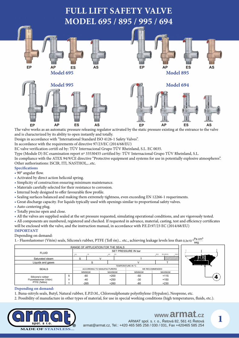
Full lift safety valve model 695 / 895 / 995 / 694No. PIECE PIECE
MATERIALBRONZE STAINLESS STEEL
1 Body Bronze (EN-CC491K) S. steel (EN-1.4408)2 Plug Brass (EN-CW617N) S. steel (EN-1.4401)3 Shaft S. steel (EN-1.4305) S. steel (EN-1.4305)
4 SealSilicone’s rubber Silicone’s rubberFluorelastomer (Viton) Fluorelastomer (Viton)
5 Limiter ring S. steel (EN-1.4310) S. steel (EN-1.4310)6 End-stop7 Spring press Brass (EN-CW617N) S. steel (EN-1.4305)8 Spring S. steel (EN-1.4310) S. steel (EN-1.4310)9 Clip S. steel (EN-1.4310) S. steel (EN-1.4310)10 Lever S. steel (EN-1.4301) S. steel (EN-1.4301) 11 Sealing wire Sealing wire Sealing wire12 Characteristic plate Aluminium Aluminium13 Seal Plastic Plastic14 Cap Brass (EN-CW617N) S. steel (EN-1.4305) 15 Hood coupling16 Piston Brass (EN-CW617N) S. steel (EN-1.4305)17 Piston Spring S. steel (EN-1.4310) S. steel (EN-1.4310)18 Inlet clamp - S. steel (EN-1.4404)19 Outlet clamp - S. steel (EN-1.4404)20 O-ring Fluorelastomer (Viton) (1) Fluorelastomer (Viton) (1)21 Seat - S. steel (EN-1.4401)
MO
DEL
695
R1xR2 3/8”x1/2” to 1”x1”PN PMS 36 bar 40
OPERATINGCONDITIONS
PRESSURE IN bar 36 36MAX. TEMPERATURE IN şC 200 250MIN. TEMPERATURE IN şC -60 -60
895
R1xR2 3/8”x1/2” to 1”x1”PN PMS 36 bar 40
OPERATINGCONDITIONS
PRESSURE IN bar 36 36MAX. TEMPERATURE IN şC 200 250MIN. TEMPERATURE IN şC -196 -196
995
R1xR2 3/8”x1/2” to 1/2”x1/2”PN 160
OPERATINGCONDITIONS
PRESSURE IN bar - 144MAX. TEMPERATURE IN şC - 250MIN. TEMPERATURE IN şC - -60
694
DN1xDN2 10x15 to 25x25PN - 16
OPERATINGCONDITIONS
PRESSURE IN bar - 16MAX. TEMPERATURE IN şC - 250MIN. TEMPERATURE IN şC - -60
EP EPAP APES ESAS AS
1
15
4
216
17
10
11
20
13
14
9
6
8
7
910
6
7
8
2
4
1
1113
14
1
4
2
8
7
615
14
1113
12
1
4
2
8
7
6
121113
1
4
2
5
3
8
7
6
15
14
2011
13
910
17
16
1113
109
14
6
7
8
3
5
2
4
1 1
4
2
5
3
8
7
6
15
14
1211
13
1
4
2
5
3
8
7
6
1211
13
1
21
1
18
19
Mod. 695/895do=8,00
Mod. 995do=4,00
Mod. 694do=8,00
Mod. 695/895do=9,75 do=13,00
MADE OF STAINLESS ...
�
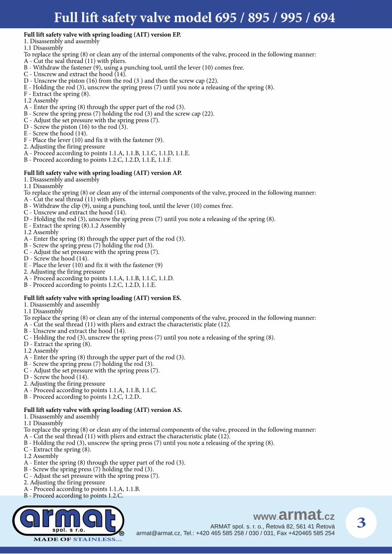
Full lift safety valve with spring loading (AIT) version EP.1. Disassembly and assembly1.1 DisassmblyTo replace the spring (8) or clean any of the internal components of the valve, proceed in the following manner:A - Cut the seal thread (11) with pliers.B - Withdraw the fastener (9), using a punching tool, until the lever (10) comes free.C - Unscrew and extract the hood (14).D - Unscrew the piston (16) from the rod (3 ) and then the screw cap (22).E - Holding the rod (3), unscrew the spring press (7) until you note a releasing of the spring (8).F - Extract the spring (8).1.2 AssemblyA - Enter the spring (8) through the upper part of the rod (3).B - Screw the spring press (7) holding the rod (3) and the screw cap (22).C - Adjust the set pressure with the spring press (7).D - Screw the piston (16) to the rod (3).E - Screw the hood (14).F - Place the lever (10) and fix it with the fastener (9).2. Adjusting the firing pressureA - Proceed according to points 1.1.A, 1.1.B, 1.1.C, 1.1.D, 1.1.E.B - Proceed according to points 1.2.C, 1.2.D, 1.1.E, 1.1.F.
Full lift safety valve with spring loading (AIT) version AP.1. Disassembly and assembly1.1 DisassmblyTo replace the spring (8) or clean any of the internal components of the valve, proceed in the following manner:A - Cut the seal thread (11) with pliers.B - Withdraw the clip (9), using a punching tool, until the lever (10) comes free.C - Unscrew and extract the hood (14).D - Holding the rod (3), unscrew the spring press (7) until you note a releasing of the spring (8).E - Extract the spring (8).1.2 Assembly1.2 AssemblyA - Enter the spring (8) through the upper part of the rod (3).B - Screw the spring press (7) holding the rod (3).C - Adjust the set pressure with the spring press (7).D - Screw the hood (14).E - Place the lever (10) and fix it with the fastener (9)2. Adjusting the firing pressureA - Proceed according to points 1.1.A, 1.1.B, 1.1.C, 1.1.D.B - Proceed according to points 1.2.C, 1.2.D, 1.1.E.
Full lift safety valve with spring loading (AIT) version ES.1. Disassembly and assembly1.1 DisassmblyTo replace the spring (8) or clean any of the internal components of the valve, proceed in the following manner:A - Cut the seal thread (11) with pliers and extract the characteristic plate (12).B - Unscrew and extract the hood (14).C - Holding the rod (3), unscrew the spring press (7) until you note a releasing of the spring (8).D - Extract the spring (8).1.2 AssemblyA - Enter the spring (8) through the upper part of the rod (3).B - Screw the spring press (7) holding the rod (3).C - Adjust the set pressure with the spring press (7).D - Screw the hood (14).2. Adjusting the firing pressureA - Proceed according to points 1.1.A, 1.1.B, 1.1.C.B - Proceed according to points 1.2.C, 1.2.D..
Full lift safety valve with spring loading (AIT) version AS.1. Disassembly and assembly1.1 DisassmblyTo replace the spring (8) or clean any of the internal components of the valve, proceed in the following manner:A - Cut the seal thread (11) with pliers and extract the characteristic plate (12).B - Holding the rod (3), unscrew the spring press (7) until you note a releasing of the spring (8).C - Extract the spring (8).1.2 AssemblyA - Enter the spring (8) through the upper part of the rod (3).B - Screw the spring press (7) holding the rod (3).C - Adjust the set pressure with the spring press (7).2. Adjusting the firing pressureA - Proceed according to points 1.1.A, 1.1.B.B - Proceed according to points 1.2.C.
Full lift safety valve model 695 / 895 / 995 / 694
MADE OF STAINLESS ...
4
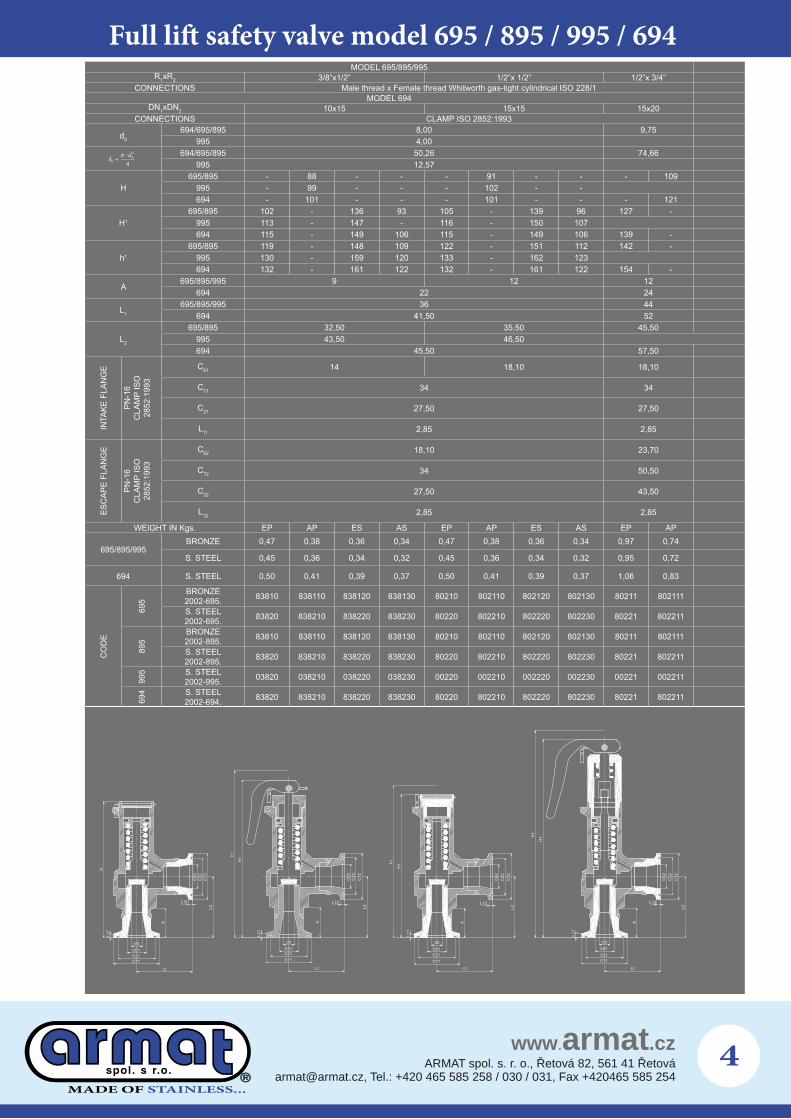
Full lift safety valve model 695 / 895 / 995 / 694MODEL 695/895/995
R1xR2 3/8”x1/2” 1/2”x 1/2” 1/2”x 3/4”CONNECTIONS Male thread x Female thread Whitworth gas-tight cylindrical ISO 228/1
MODEL 694DN1xDN2 10x15 15x15 15x20
CONNECTIONS CLAMP ISO 2852:1993
d0
694/695/895 8,00 9,75995 4,00
694/695/895 50,26 74,66995 12,57
H695/895 - 88 - - - 91 - - - 109
995 - 99 - - - 102 - -694 - 101 - - - 101 - - - 121
H1
695/895 102 - 136 93 105 - 139 96 127 -995 113 - 147 - 116 - 150 107694 115 - 149 106 115 - 149 106 139 -
h1
695/895 119 - 148 109 122 - 151 112 142 -995 130 - 159 120 133 - 162 123694 132 - 161 122 132 - 161 122 154 -
A695/895/995 9 12 12
694 22 24
L1
695/895/995 36 44694 41,50 52
L2
695/895 32,50 35,50 45,50995 43,50 46,50694 45,50 57,50
INTA
KE F
LAN
GE
PN-1
6 C
LAM
P IS
O
2852
:199
3
C61 14 18,10 18,10
C71 34 34
C21 27,50 27,50
L11 2,85 2,85
ESC
APE
FLAN
GE
PN-1
6 C
LAM
P IS
O
2852
:199
3
C62 18,10 23,70
C72 34 50,50
C22 27,50 43,50
L12 2,85 2,85
WEIGHT IN Kgs. EP AP ES AS EP AP ES AS EP AP
695/895/995BRONZE 0,47 0,38 0,36 0,34 0,47 0,38 0,36 0,34 0,97 0,74
S. STEEL 0,45 0,36 0,34 0,32 0,45 0,36 0,34 0,32 0,95 0,72
694 S. STEEL 0,50 0,41 0,39 0,37 0,50 0,41 0,39 0,37 1,06 0,83
CO
DE
695
BRONZE 2002-695. 83810 838110 838120 838130 80210 802110 802120 802130 80211 802111
S. STEEL 2002-695. 83820 838210 838220 838230 80220 802210 802220 802230 80221 802211
895
BRONZE 2002-895. 83810 838110 838120 838130 80210 802110 802120 802130 80211 802111
S. STEEL 2002-895. 83820 838210 838220 838230 80220 802210 802220 802230 80221 802211
995 S. STEEL
2002-995. 03820 038210 038220 038230 00220 002210 002220 002230 00221 002211
694 S. STEEL
2002-694. 83820 838210 838220 838230 80220 802210 802220 802230 80221 802211
H
1H
1h
1H
1h
1h 1H
C71C21C61d0
11L
A
L1
26C
22C
27C
L12
11L
d0C61C21C71
A
2L
L12
26C
22C
27C
d0C61C21C71
11L
A
L1
L12
2L
26C
22C
27C
2 6C
22C
27C
2L
L12
A
11L
d0C61C21C71
2L
L1 L1
MADE OF STAINLESS ...
5
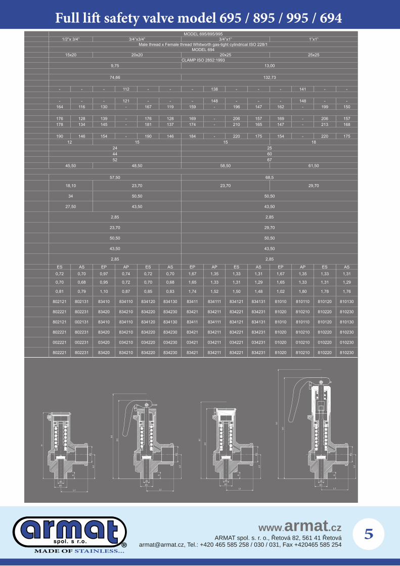
MODEL 695/895/9951/2”x 3/4” 3/4”x3/4” 3/4”x1” 1”x1”
Male thread x Female thread Whitworth gas-tight cylindrical ISO 228/1MODEL 694
15x20 20x20 20x25 25x25CLAMP ISO 2852:1993
9,75 13,00
74,66 132,73
- - - 112 - - - 138 - - - 141 - -
- - - 121 - - - 148 - - - 148 - -164 116 130 - 167 119 159 - 196 147 162 - 199 150
176 128 139 - 176 128 169 - 206 157 169 - 206 157178 134 145 - 181 137 174 - 210 165 147 - 213 168
190 146 154 - 190 146 184 - 220 175 154 - 220 17512 15 15 18
24 2544 6052 67
45,50 48,50 58,50 61,50
57,50 68,5
18,10 23,70 23,70 29,70
34 50,50 50,50
27,50 43,50 43,50
2,85 2,85
23,70 29,70
50,50 50,50
43,50 43,50
2,85 2,85
ES AS EP AP ES AS EP AP ES AS EP AP ES AS0,72 0,70 0,97 0,74 0,72 0,70 1,67 1,35 1,33 1,31 1,67 1,35 1,33 1,31
0,70 0,68 0,95 0,72 0,70 0,68 1,65 1,33 1,31 1,29 1,65 1,33 1,31 1,29
0,81 0,79 1,10 0,87 0,85 0,83 1,74 1,52 1,50 1,48 1,02 1,80 1,78 1,76
802121 802131 83410 834110 834120 834130 83411 834111 834121 834131 81010 810110 810120 810130
802221 802231 83420 834210 834220 834230 83421 834211 834221 834231 81020 810210 810220 810230
802121 002131 83410 834110 834120 834130 83411 834111 834121 834131 81010 810110 810120 810130
802221 802231 83420 834210 834220 834230 83421 834211 834221 834231 81020 810210 810220 810230
002221 002231 03420 034210 034220 034230 03421 034211 034221 034231 01020 010210 010220 010230
802221 802231 83420 834210 834220 834230 83421 834211 834221 834231 81020 810210 810220 810230
H
R1
d0
L1
A
L2R
2
H1
d0
R1
L1
A
L2R
2
d0
R1
A
R2
L2
H1
L1
R2
L2
d0
A
R1
H1
L1
Full lift safety valve model 695 / 895 / 995 / 694
MADE OF STAINLESS ...
6
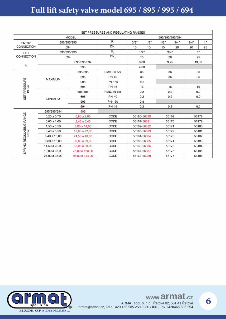
SET PRESSURES AND REGULATING RANGES
MODEL 695/895/995/694
ENTRYCONNECTION
695/895/995 R1 3/8” 1/2” 1/2” 3/4” 3/4” 1”
694 DN1 10 15 15 20 20 25
EXITCONNECTION
695/895/995 R2 1/2” 3/4” 1”
694 DN2 15 20 25
d0
695/895/694 8,00 9,75 13,00
995 4,00
SE
T P
RE
SS
UR
EIN
bar
MAXIMUM
695/895 PMS. 36 bar 36 36 36
695 PN-40 36 36 36
995 PN-160 144
694 PN-16 16 16 16
MINIMUM
695/895 PMS. 36 bar 0,2 0,2 0,2
695 PN-40 0,2 0,2 0,2
995 PN-160 0,8
694 PN-16 0,2 0,2 0,2
SP
RIN
G R
EG
ULA
T IN
G R
AN
GE
IN
bar
695/895/694 995
0,20 a 0,70 0,80 a 2,80 CODE 56160-56330 56169 56178
0,60 a 1,60 2,40 a 6,40 CODE 56161-56331 56170 56179
1,50 a 3,50 6,00 a 14,00 CODE 56162-56332 56171 56180
3,40 a 5,50 13,60 a 22,00 CODE 56163-56333 56172 56181
5,40 a 10,00 21,50 a 40,00 CODE 56164-56334 56173 56182
9,80 a 15,00 39,00 a 60,00 CODE 56165-56335 56174 56183
14,50 a 20,00 58,00 a 80,00 CODE 56166-56336 56175 56184
19,00 a 25,00 76,00 a 100,00 CODE 56167-56337 56176 56185
24,00 a 36,00 96,00 a 144,00 CODE 56168-56338 56177 56186
Full lift safety valve model 695 / 895 / 995 / 694

MADE OF STAINLESS ...
�
Full lift safety valve model 695 / 895 / 995 / 694
RECOMMENDED RANGES OF APPLICATION
MODEL695/895/995/694
AP AS EP ES
FLUID
SATURATED STEAM * * * *
GASESINERT * * * *
NON INERT
LIQUIDS
OPENING PRESSURE IN %OF THE SET PRESSURE +10%
CLOSURE PRESSURE IN %OF THE SET PRESSURE -10%
1,28
1,26
1,24
1,22
1,20
1,18
1,16
1,14
1,12
1,10
1,08
1,06
1,04
1,02
1,0010 15 20 25
% p
Overpressure factorsMultiply the discharge capacity obtai -ned from the tables, by the correction factor, in order to obtain the dischar-ge capacity at required overpressure.
0,8
0,7
0,6
0,5
0,4
0,3
0,20,2 0,3 0,4 0,5 0,6 0,7 0,8
d LÍQUIDOS
VAPOR SATURADOGASES
do=13,00
do=9,75
do=8,00
do=13,00
do=9,75
do=8,00
do=4,00do=4,00
pap
LIQUIDS
SATURATED STEAMGASES
AirSaturated steam
Water
MADE OF STAINLESS ...
8
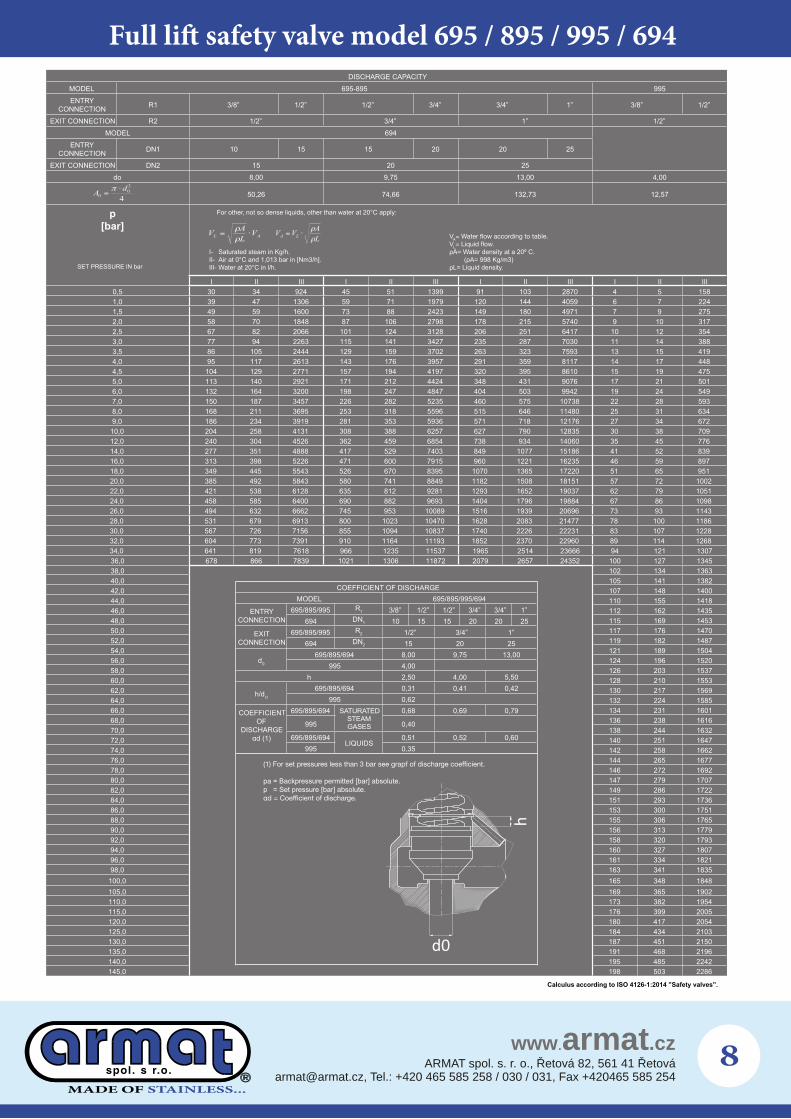
Full lift safety valve model 695 / 895 / 995 / 694DISCHARGE CAPACITY
MODEL 695-895 995ENTRY
CONNECTION R1 3/8” 1/2” 1/2” 3/4” 3/4” 1” 3/8” 1/2”
EXIT CONNECTION R2 1/2” 3/4” 1” 1/2”MODEL 694
ENTRY CONNECTION DN1 10 15 15 20 20 25
EXIT CONNECTION DN2 15 20 25do 8,00 9,75 13,00 4,00
50,26 74,66 132,73 12,57
I II III I II III I II III I II III0,5 30 34 924 45 51 1399 91 103 2870 4 5 1581,0 39 47 1306 59 71 1979 120 144 4059 6 7 2241,5 49 59 1600 73 88 2423 149 180 4971 7 9 2752,0 58 70 1848 87 106 2798 178 215 5740 9 10 3172,5 67 82 2066 101 124 3128 206 251 6417 10 12 3543,0 77 94 2263 115 141 3427 235 287 7030 11 14 3883,5 86 105 2444 129 159 3702 263 323 7593 13 15 4194,0 95 117 2613 143 176 3957 291 359 8117 14 17 4484,5 104 129 2771 157 194 4197 320 395 8610 15 19 4755,0 113 140 2921 171 212 4424 348 431 9076 17 21 5016,0 132 164 3200 198 247 4847 404 503 9942 19 24 5497,0 150 187 3457 226 282 5235 460 575 10738 22 28 5938,0 168 211 3695 253 318 5596 515 646 11480 25 31 6349,0 186 234 3919 281 353 5936 571 718 12176 27 34 672
10,0 204 258 4131 308 388 6257 627 790 12835 30 38 70912,0 240 304 4526 362 459 6854 738 934 14060 35 45 77614,0 277 351 4888 417 529 7403 849 1077 15186 41 52 83916,0 313 398 5226 471 600 7915 960 1221 16235 46 59 89718,0 349 445 5543 526 670 8395 1070 1365 17220 51 65 95120,0 385 492 5843 580 741 8849 1182 1508 18151 57 72 100222,0 421 538 6128 635 812 9281 1293 1652 19037 62 79 105124,0 458 585 6400 690 882 9693 1404 1796 19884 67 86 109826,0 494 632 6662 745 953 10089 1516 1939 20696 73 93 114328,0 531 679 6913 800 1023 10470 1628 2083 21477 78 100 118630,0 567 726 7156 855 1094 10837 1740 2226 22231 83 107 122832,0 604 773 7391 910 1164 11193 1852 2370 22960 89 114 126834,0 641 819 7618 966 1235 11537 1965 2514 23666 94 121 130736,0 678 866 7839 1021 1306 11872 2079 2657 24352 100 127 134538,0 102 134 136340,0 105 141 138242,0 107 148 140044,0 110 155 141846,0 112 162 143548,0 115 169 145350,0 117 176 147052,0 119 182 148754,0 121 189 150456,0 124 196 152058,0 126 203 153760,0 128 210 155362,0 130 217 156964,0 132 224 158566,0 134 231 160168,0 136 238 161670,0 138 244 163272,0 140 251 164774,0 142 258 166276,0 144 265 167778,0 146 272 169280,0 147 279 170782,0 149 286 172284,0 151 293 173686,0 153 300 175188,0 155 306 176590,0 156 313 177992,0 158 320 179394,0 160 327 180796,0 161 334 182198,0 163 341 1835
100,0 165 348 1848105,0 169 365 1902110,0 173 382 1954115,0 176 399 2005120,0 180 417 2054125,0 184 434 2103130,0 187 451 2150135,0 191 468 2196140,0 195 485 2242145,0 198 503 2286
p[bar]
SET PRESSURE IN bar
For other, not so dense liquids, other than water at 20°C apply:
VAVL
I- Saturated steam in Kg/h.II- Air at 0°C and 1,013 bar in [Nm3/h].III- Water at 20°C in l/h.
Calculus according to ISO 4126-1:2014 ”Safety valves”.
d0
h
COEFFICIENT OF DISCHARGEMODEL 695/895/995/694
ENTRYCONNECTION
695/895/995 R1 3/8” 1/2” 1/2” 3/4” 3/4” 1”694 DN1 10 15 15 20 20 25
EXITCONNECTION
695/895/995 R2 1/2” 3/4” 1”694 DN2 15 20 25
d0
695/895/694 8,00 9,75 13,00995 4,00
h 2,50 4,00 5,50
h/d0
695/895/694 0,31 0,41 0,42995 0,62
COEFFICIENTOF
DISCHARGE
695/895/694 SATURATED STEAMGASES
0,68 0,69 0,79
995 0,40
695/895/694LIQUIDS
0,51 0,52 0,60995 0,35
pa = Backpressure permitted [bar] absolute.p = Set pressure [bar] absolute.