Spintronic Technology & Advance Research(STAR) Department ...
20
1 Spintronic Technology & Advance Research(STAR) Department of Civil Engineering DIPLOMA Lecture notes on Geotechnical Engineering By Pramodini Routray
Transcript of Spintronic Technology & Advance Research(STAR) Department ...

1
Spintronic Technology & Advance
Research (STAR)
Department of Civil Engineering
DIPLOMA
Lecture notes on
Geotechnical Engineering
By
Pramodini Routray

2
SYLLABUS
1
Introduction
Soil and Soil Engineering
Scope of Soil Mechanics
Origin and formation of soil
2
Preliminary Definitions and Relationship
Soil as a three Phase system.
Water Content, Density, Specific gravity, Voids ratio, Porosity, Percentage of air voids, air
content, degree of saturation, density Index, Bulk/Saturated/dry/submerged density,
Interrelationship of various soil parameters
3
Index Properties of Soil
Water Content
Specific Gravity
Particle size distribution: Sieve analysis, wet mechanical analysis, particle size distribution
curve and its uses
Consistency of Soils, Atterberg’s Limits, Plasticity Index, Consistency Index, Liquidity Index
4
Classification of Soil

3
General
I.S. Classification, Plasticity chart
5
Permeability and Seepage
Concept of Permeability, Darcy’s Law, Co-efficient of Permeability,
Factors affecting Permeability.
Constant head permeability and falling head permeability Test.
Seepage pressure, effective stress, phenomenon of quick sand
6
Compaction and Consolidation
Compaction: Compaction, Light and heavy compaction Test, Optimum Moisture
Content of Soil, Maximum dry density, Zero air void line, Factors affecting Compaction, Field
compaction methods and their suitability
Consolidation: Consolidation, distinction between compaction and consolidation.
Terzaghi‘s model analogy of compression/ springs showing the process of consolidation – field
implications
7
Shear Strength
7.1 Concept of shear strength, Mohr- Coulomb failure theory, Cohesion, Angle of internal
friction, strength envelope for different type of soil, Measurement of shear strength;- Direct shear
test, triaxial shear test, unconfined compression test and vane-shear test
4
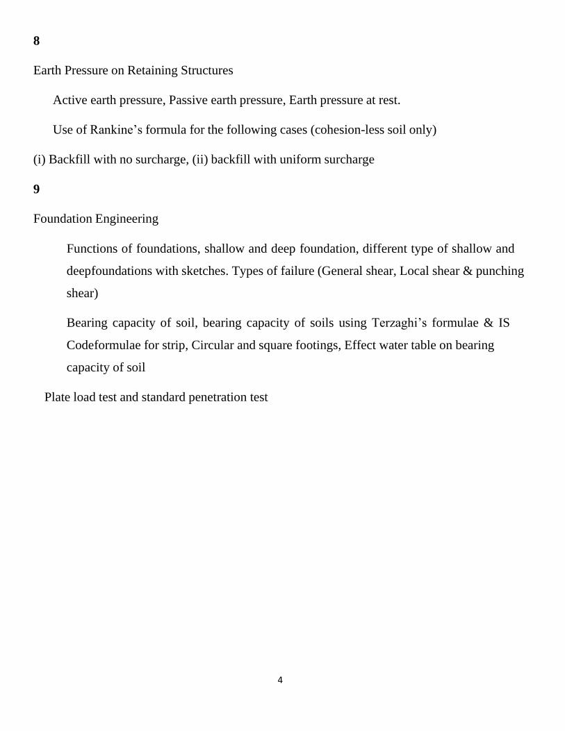
8
Earth Pressure on Retaining Structures
Active earth pressure, Passive earth pressure, Earth pressure at rest.
Use of Rankine’s formula for the following cases (cohesion-less soil only)
(i) Backfill with no surcharge, (ii) backfill with uniform surcharge
9
Foundation Engineering
Functions of foundations, shallow and deep foundation, different type of shallow and
deep foundations with sketches. Types of failure (General shear, Local shear & punching
shear)
Bearing capacity of soil, bearing capacity of soils using Terzaghi’s formulae & IS
Code formulae for strip, Circular and square footings, Effect water table on bearing
capacity of soil
Plate load test and standard penetration test

5
Chapter 1: Introduction
Soil and Soil Engineering
Definition of soil: The term ‘soil’ in soil engineering is defined as unconsolidated material, composed of soil
particles, produced by the disintegration of rocks. The voids space between the particles may contain air, water
or both. The soil particles may contain organic matter.
Definition of soil mechanics:
• The term ‘soil mechanics’ was coined by Dr. Karl Terzaghi in 1925, who is also known as the father of
soil mechanics.
• According to Terzaghi, soil mechanics is the application of the laws of mechanics & hydraulics to
engineering problems dealing with sediments & other unconsolidated accumulations of solid particles
produced by the mechanical and chemical disintegration of rook, regardless of whether or not they contain
an admixture of organic constitute.
• Soil mechanics is therefore, a branch of mechanics which deals with the action of forces on soil and
with the flow of water in soil.
Definition of soil engineering:
• Soil engineering is an applied science dealing with the applications of principals of soil mechanics to
practical problems.
• It has a much wider scope than soil mechanics, as it deals with all engineering problems related with soils.
It includes site investigations, design and construction of foundations, earth-retaining structures and earth
structures.
Definition of geotechnical engineering:
• Geotechnical is a broader term which includes soil engineering, rock mechanics and geology.
• Sometimes geotechnical engineering is used synonymously with soil engineering.
Scope of Soil Mechanics:
Soil Mechanics is a basic subject and its scope will never end because all structures are built on soil and for
buildings and structures to perform well and for a long time, soil tests should be done so that to know about
the properties of soil and its characteristics.
Origin and formation of soil:
• In a broad sense, soil may be thought of an incidental material in vast geological cycle which has been
going on continuously for millions of years of geological time.

6
• The geological cycle consists of 3 phases, Erosion, Transportation and deposition & Earth Movement.
a) Erosion Phase:
• The cycle starts with erosional phase in which there is degradation of exposed rock by weathering
process.
• The weathering process may be
i. Physical weathering
ii. Chemical weathering
i. Physical weathering :
➢ The physical weathering process may be
❖ Erosion of rock caused by the action of wind, water, glaciers.
❖ Disintegration caused by alternate freezing and thawing in cracks in the rock.
➢ The resulting soil particles retain the same composition as that of parent rock.
➢ Their shape can be indicated by terms such as angular, rounded, flat and elongated.
➢ Gravel and sand fall into this group.
ii. Chemical weathering:
➢ The chemical process results in changes in the mineral form of parent rock due to the action of water.
➢ Chemical weathering results in the formation of group of crystalline particles of colloidal size (< 2μ)
known as clay mineral.
➢ If the products of rock weathering are still located at the place where they originated, they are called
residual soil.
b) Transportation/Deposition:
➢ In the second phase, the fragmented material is transported by agent such as wind, water or ice to new
locations.
➢ Soil transported from their origin by wind, water, ice or any other agency and has been deposited is
called transported soil. They have generally small grain size, large amount of pores.
➢ According to the transporting agency, soils are classified as:
• Alluvial deposit – deposited by river water.
• Lacustrine deposit – deposited by still water like lakes.
• Marine deposit – deposited by sea water.
• Aeolian deposit – transported by wind.
• Glacial deposit – transported by ice.
• Colluvial soil – deposited by gravity. ( e.g. talus)

7
Chapter 2: Preliminary Definitions and Relationship
Soil as a three Phase system.
• A soil mass consists of solid particles which form a porous structure. The voids in the soil mass may be
filled with air, with water or partly with air and partly with water. The three constituents are blended
together to form a complex material.
• However, for convenience, all the solid particles are segregated and placed in the lower layer of the three
phase diagram.
• Likewise water and air particles are placed separately, as shown in figure below.
• The 3-phase diagram is also known as Block diagram.
• It may be noted that the 3-constituents cannot be actually segregated, as shown.
• A 3-phase diagram is an artifice used for easy understanding and convenience in calculation.
• Soil can be either two-phase or three-phase composition.
• Fully saturated soil and fully dry soil are two phase system.
• Partially saturated soil are three phase system.
Three phase system Two phase system Two phase system

8
Where
Va= Volume of air Wa = Weight of air = 0
Vw = Volume of water Ww = Weight of water
V = Total volume of Soil mass Ws = Weight of soil solid
Vv = Volume of voids W = Total weight of soil mass
Vs = Volume of Solid Wsat = Saturated weight of soil mass
Important definitions:
1. Water content (w):
• Water content or moisture content of a soil is defined as the ratio of weight of water to weight of solids
(dry weight) of the soil mass.
w = Ww x 100 ; w ≥ 0 Ws
• It is denoted by the letter symbol w and is commonly expressed as percentage i.e. 20%, 50% etc.
• The minimum value of water content is 0.
• There is no upper limit for water content.
• Generally fine grained soil have higher water content as compared to course grained soil.
2. Void ratio (e):
• Void ratio (e) is the ratio of the volume of voids (Vv) to the volume of soil solids (Vs), and is expressed as
a decimal.
• There is no upper limit of void ratio in soil suspension.
• Void ratio of fine grained soil are generally higher than those of course grained soil.
• Size of void in course grained soil are generally larger than that in fine grained soil.

9
Total volume V is a variable quantity. But, since solids are incompressible, Vs remain invariant in the total
volume V of the soil.
3. Porosity (n):
• Porosity (n) is the ratio of the volume of voids to the total volume of soil (V), and is expressed as a percentage.
• V= VV + VS , VV = VW + Va
• The porosity of soil cannot exceed 100% hence it has a upper limit of 100% or 1.
• Both porosity and void ratio are measured of denseness or looseness of soil.
Note:
4. Degree of saturation (S):
• Degree of saturation of soil mass is defined as the ratio of volume of water in the voids to volume of
voids.
• S = Vw, 0 ≤ S ≤ 100 Vv
• For a fully saturated soil mass Vv = Vw, hence for the saturated soil mass S = 100% .
• For fully dry soil Vw = 0 , hence for a saturated soil mass s = 0%
• For partially saturated soil mass degree of saturation of soil mass varies between 0 – 100%, which is
most common condition in nature.
5. Percentage Air voids (na):
• Percentage air voids (na) is the ratio of the volume of air to the total volume.
• na = Va
V × 100
6. Air content (ac):
• Air content (ac) is the ratio of the volume of air (Va) to the volume of voids Vv.

10
s
w
d
sat
na = n × ac
• na = Va
= Va × Vv
= Vv
× Va
= n × ac V V × Vv V Vv
7. Bulk unit weight (γt/𝛾):
• Bulk unit weight of a soil mass is defined as the weight per unit volume.
• γt =
W =
Ws + Ww
V Vw+ Va+Vs
• It is generally expressed as KN/m3, N/m3, kgf/ KN/cm3
8. Unit weight of Solid (γs):
• It is defined as the ratio of weight of solids to weight of volume of solids. It is also called absolute unit
weight of soil mass.
• γ = Ws Vs
9. Unit weight of water (γw):
• γ = Ww
Vw
• The value of γw changes with temperature but usually we take γw as 9.81 kN/m3 which is at 4oC.
10. Dry unit weight (γd):
• It is defined as weight of soil solid ( or weight of dry soil) per total volume of soil.
• Unit is KN/m3, N/m3, kgf/ KN/cm3
• γ = Ws
V
• Dry unit weight is used as a measure of denseness of soil. A high value of dry unit weight indicates that
more solids are packed in unit volume of soil hence a more compact soil.
11. Saturated unit weight (γsat):
• It is defined as the bulk unit weight of soil mass in saturated condition.
• γ =
Wt. of Saturated soil
Volume of soil
12. Submerged unit weight (γsub or γ,):
• It is defined as the weight of submerged soil per total volume of soil mass. When the soil exists below the
ground water table, the soil mass is said to be in submerged condition.
11
sub
Bulk unit weight = Saturated unit weight , ( when soil is fully saturated)
Bulk unit weight = Dry unit weight, ( when soil is completely in dry condition )
• γ =
Wt. of Submerged soil
Volume of soil
• γ, = γsat - γw
Note:
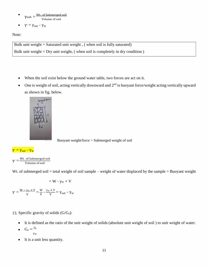
• When the soil exist below the ground water table, two forces are act on it.
• One is weight of soil, acting vertically downward and 2nd is buoyant force/weight acting vertically upward
as shown in fig. below.
Buoyant weight/force = Submerged weight of soil
γ, = γsat - γw
γ, = Wt. of Submerged soil
Volume of soil
Wt. of submerged soil = total weight of soil sample – weight of water displaced by the sample = Buoyant weight
= W - γw × V
γ, = W − γw × V
= W
- γw × V
= γsat - γw
V V V
13. Specific gravity of solids (G/Gs):
• It is defined as the ratio of the unit weight of solids (absolute unit weight of soil ) to unit weight of water.
• Gs = γs
γw
• It is a unit less quantity.
12
• This is also known as Absolute specific gravity or Grain specific gravity.
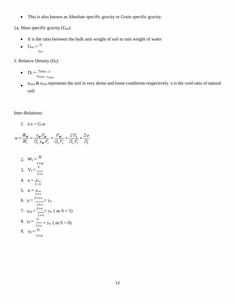
14. Mass specific gravity (Gm):
• It is the ratio between the bulk unit weight of soil to unit weight of water
• Gm = γt
γw
5. Relative Density (Dr):
• Dr = emax− e
emax− emin
• emax & emin represents the soil in very dense and loose conditions respectively. e is the void ratio of natural
soil.
Inter-Relations:
1. e.s = G.w
2. Ws =
W
1+w
3. Vs = V
1+e
4. e = n 1−n
5. n = e 1+e
6. γt = 𝐺+𝑒.𝑠
× γw
1+𝑒
7. γsat = 𝐺+𝑒
× γw ( as S = 1) 1+𝑒
8. γd = 𝐺
1+𝑒
9. γd = γt
1+w
× γw ( as S = 0)
13
Chapter 3: Index Properties of Soil
➢ In this chapter, we shall describe the methods of determining those properties of soil which are used in
their identification and classification.
➢ These include the determination of
i. Water content (w)
ii. Specific gravity (G)
iii. Particle size distribution
iv. Consistency limits
v. In-situ density
vi. Density index
➢ These properties are known as index properties.
i. Water content (w):
➢ Water content of soil is an important soil parameter which significantly influences the behavior of soil,
particularly cohesive soils.
➢ Water content and unit weight changes during transportation and storage. Hence it is important to
determine it before carrying out any other tests.
➢ Water content determination is also important because some physical state properties are calculated using
water content following the practical measurements of others e.g. dry unit weight from bulk unit weight.
➢ The water content of a soil sample can be determined by any one of the following methods:
a) Oven drying method
b) Torsion balance method
c) Pycnometer method
d) Sand Bath method
e) Alcohol method
f) Calcium carbide method
g) Radiation method
a) Oven drying method:
➢ The oven drying method is a standard laboratory method. This is very accurate method.
➢ The soil sample is taken in a small, non-corrodible, air tight container.

14
Moist soil
Soil
Water
Water
➢ The soil sample in container is then dried at temperature of 105-110oC for 24 hour in laboratory. Above
110 oC, water of crystallization may lost.
➢ Water crystallization is the water in the molecular structure.
➢ For soil containing significant amount of organic matter, a temperature of 60oC to 80oC is recommended.
➢ If W1 = weight of container, W2 = wt. of container + wt. of moist soil and W3 = wt. of container + wt. of
dry soil, then water content is given by:
w = Ww
= W2−W3
Ws W3−w1
b) Pycnometer method:
➢ A pycnometer is a glass jar of about 1 liter capacity and fitted with a brass conical cap means of a screw-
type cover. The cap has a small hole of 6mm dia. At its apex.
➢ The pycnometer meter method for determination of water content can be used only if the specific gravity
of solid (G) particle is known.
➢ First the weight of empty pycnometer is determined (W1) in the dry condition. Then the sample of moist
soil, is placed in the pycnometer and its weight with the soil is determined (W2).
➢ The remaining volume of the pycnometer is then gradually filled with distilled water or kerosene. The
weight of pycnometer, soil and water is obtained (W3).
➢ Lastly the bottle is emptied, thoroughly cleaned and filled with distilled water or kerosene, and its weight
taken (W4).
W1 W2 W3 W4
➢ Ww = W2 – W1 – WS

15
Dry soil Soil
Water
Water
w = WW
= W2− W1− WS
WS WS
W4 – W1 = W3 – W1 – WS + Ws γw
Gs γw
WS = [(W3 –W4) × GS] / GS – 1
w = [(W2 – W1) / [{(W3 – W4).GS} / (GS – 1)]] – 1
w = [𝑊2− 𝑊1 ×
(𝐺𝑠−1) – 1]
𝑊3− 𝑊4 𝐺𝑠
➢ Tish method is more suitable for cohesion less soil as in case cohesive soil removal of entrapped air is
difficult.
ii) Specific gravity of soil particles:
𝑊𝑠
➢ We know G = γs = 𝑉𝑠 γw
𝑊𝑤
𝑉𝑤
➢ If Vs = Vw, G = Ws
= Ms ×g
= Ms
Ww Mw ×g Mw
➢ Therefore Sp. Gravity of a soil particle is the ratio between mass of soil solid to mass of equivalent volume
of water at same temperature.
Determination of sp. Gravity:
Sp. gravity of soil is determined by 2- methods:
a) Density bottle method
b) Pycnometer method
Density bottle method is more accurate and suitable for all type of soil. But pycnometer method is suitable for
course grained soil.
a) Density bottle method:
M1 M2 M3 M4

16
t C
Dry soil Soil
Water
Water
G = Ms
= M2− M1
Mw (M4− M1)−(M3− M2)
Procedure:
➢ A clean and empty density bottle is taken and weighted. Let the mass be M1.
➢ Again the density bottle is poured with some dry soil whose sp. gravity is to determined and the whole
assembly is weighted. Let the mass be M2.
➢ Again the whole assembly is completely filled with water and weighted. Let the mass be M3.
➢ Again the density bottle is cleaned and filled with water alone and weighted. Let the mass be M4.
➢ Then, the sp. gravity G = Ms = M2− M1 Mw (M4− M1)−(M3− M2)
➢ When kerosene is used in case of water, then the sp. gravity of soil G = M2− M1 (M4− M1)−(M3− M2)
× Gk.
Where Gk = sp. gravity of kerosene.
➢ Generally sp. gravity test is carried out on 27℃.
➢ Then sp. gravity of soil at t℃ = G o = G27℃ × G of distilled water at 27℃
.
G of distilled water at t℃
b) Pycnometer method:
➢ This method is same as pycnometer method of water content determination with the difference that here
dry soil sample is taken instead of moist soil sample as was taken in water contents determination.
W1 W2 W3 W4
Sp. gravity G = wt. of solid
wt. of equivalent volume of water
Wt. of solid = W2 - W1
Wt. of equivalent volume of water = (W4 - W1) – (W3 – W2)
G = W2− W1
(W4− W1)−(W3− W2)

17
➢ Sp. gravity values are generally reported at 27℃.
iv) Particle size distribution:
➢ The classification of soils according to their size is known as particle size distribution.
➢ It is done by 2-methods.
a. Sieve analysis
b. Sedimentation analysis for particles of size less than 75μ
a) Sieve analysis:
➢ It is done for a soil which size lies more than 75μ.
➢ In this process sieves are places one over another in decreasing order of their aperture size.
➢ The sieve analysis is of 2 types
i. Coarse sieve analysis; which consist of sieving of soil through 40mm, 20mm, 10mm and
4.75mm IS sieve.
ii. Fine sieve analysis; which consist of sieving of soil though 2mm, 1mm, 600μ, 425μ, 212μ, 150μ,
75μ IS sieve.
Procedure of sieve analysis:
➢ The soil sample is tested is dried, lumps are broken if necessary, and the sample is pass through the
series of sieves by shaking.
➢ The fraction retained on and passing 2mm IS sieve are tested separately.
18
➢ An automatic sieve shaker, run by an electric motor, may be used; about 10 to 15 minutes of shaking is
considered as adequate.
➢ Larger particles are caught on the upper sieves, while the smaller ones is filter through to be caught on
one of the smaller underling sieves.
➢ The material retained on any particular sieve should naturally include that retained on the sieves on the
top of it, since the sieves are arranged with the aperture size decreasing from top to bottom.
➢ The weight of the material retained on each sieve is converted to a percentage of the total sample.
➢ The percentage material finer than a sieve size is obtained by subtracting tis from 100.
➢ The materials passing the bottom most sieve, which is usually 75μ sieve, is used to conduct the
sedimentation analysis for the fine fraction.
➢ If the soil is clayey in nature the fine fraction cannot be easily passed through the 75μ sieve in dry
condition.
➢ In such case, the material is to be washed through it with water, until the wash water is fairly clean.
➢ The material which passes through the sieve is obtained by evaporation. This is called wet sieve
analysis, may be required in case of cohesive granular soil.
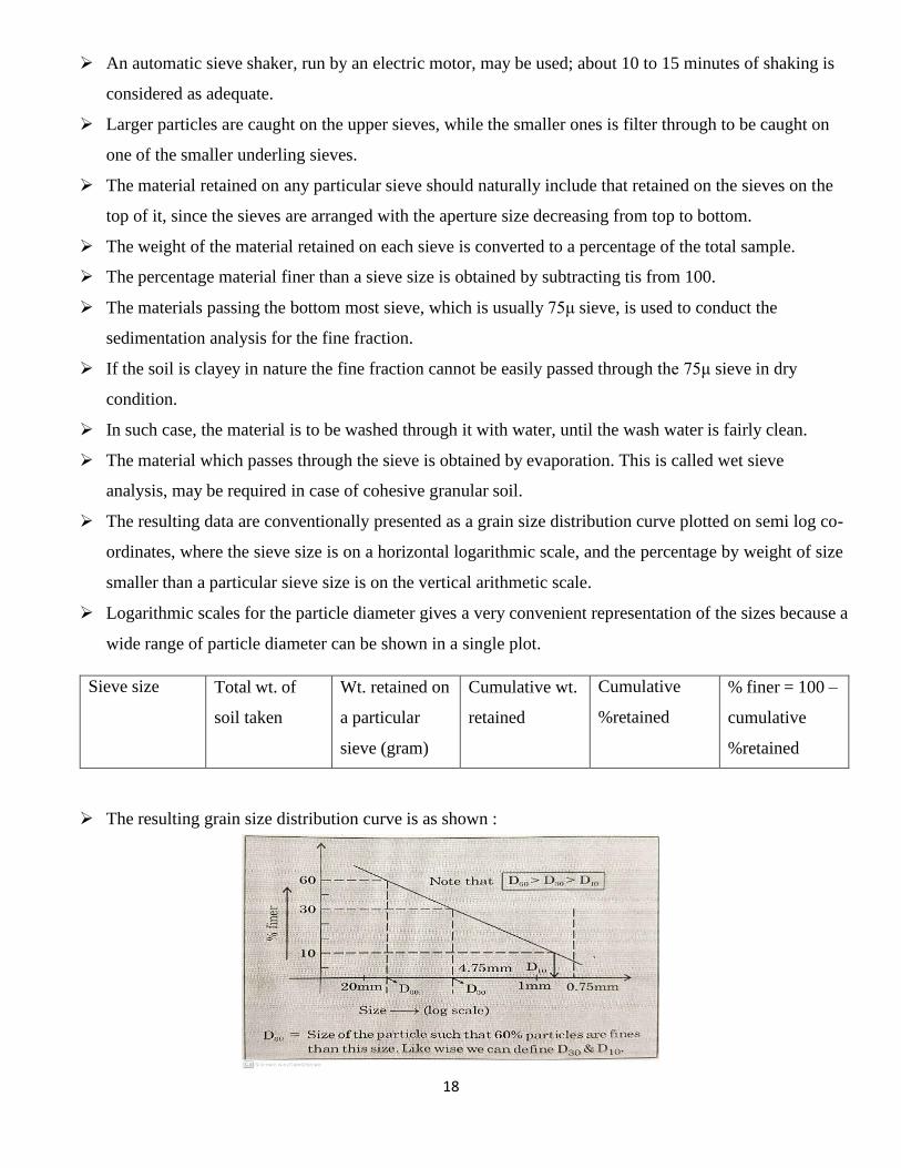
➢ The resulting data are conventionally presented as a grain size distribution curve plotted on semi log co-
ordinates, where the sieve size is on a horizontal logarithmic scale, and the percentage by weight of size
smaller than a particular sieve size is on the vertical arithmetic scale.
➢ Logarithmic scales for the particle diameter gives a very convenient representation of the sizes because a
wide range of particle diameter can be shown in a single plot.
Sieve size Total wt. of
soil taken
Wt. retained on
a particular
sieve (gram)
Cumulative wt.
retained
Cumulative
%retained
% finer = 100 –
cumulative
%retained
➢ The resulting grain size distribution curve is as shown :
19
D
➢ Actually sieve size is assumed to correspond to size of particle.
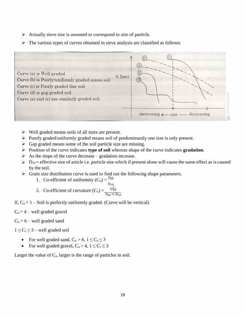
➢ The various types of curves obtained in sieve analysis are classified as follows:
➢ Well graded means soils of all sizes are present.
➢ Poorly graded/uniformly graded means soil of predominantly one size is only present.
➢ Gap graded means some of the soil particle size are missing.
➢ Position of the curve indicates type of soil whereas shape of the curve indicates gradation.
➢ As the slope of the curve decrease – gradation increase.
➢ D10 = effective size of article i.e. particle size which if present alone will cause the same effect as is caused
by the soil.
➢ Grain size distribution curve is used to find out the following shape parameters.
1. Co-efficient of uniformity (Cu) = D60
D10
2
2. Co-efficient of curvature (Cc) = 30 D60 × D10
If, Cu = 1 – Soil is perfectly uniformly graded. (Curve will be vertical)
Cu > 4 – well graded gravel
Cu > 6 – well graded sand
1 ≤ Cc ≤ 3 – well graded soil
• For well graded sand, Cu > 6, 1 ≤ Cc ≤ 3
• For well graded gravel, Cu > 4, 1 ≤ Cc ≤ 3
Larger the value of Cu, larger is the range of particles in soil.

20