Karnaugh Map Method for Memristive and Spintronic ...
11
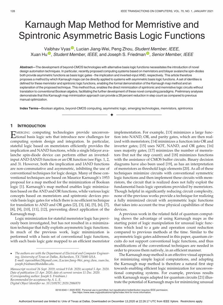
Karnaugh Map Method for Memristive and Spintronic Asymmetric Basis Logic Functions Vaibhav Vyas , Lucian Jiang-Wei, Peng Zhou, Student Member, IEEE, Xuan Hu , Student Member, IEEE, and Joseph S. Friedman , Senior Member, IEEE Abstract—The development of beyond-CMOS technologies with alternative basis logic functions necessitates the introduction of novel design automation techniques. In particular, recently proposed computing systems based on memristors and bilayer avalanche spin-diodes both provide asymmetric functions as basis logic gates - the implication and inverted-input AND, respectively. This article therefore proposes a method by which Karnaugh maps can be directly applied to systems with asymmetric basis logic functions. A set of identities is defined for these memristor and spintronic logic functions, enabling the formal demonstration of the Karnaugh map method and an explanation of the proposed technique. This method thus, enables the direct minimization of spintronic and memristive logic circuits without translation to conventional Boolean algebra, facilitating the further development of these novel computing paradigms. Preliminary analyses demonstrate that this Karnaugh map minimization approach can provide a 28 percent reduction in step count as compared to previous manual optimization. Index Terms—Boolean algebra, beyond-CMOS computing, asymmetric logic, emerging technologies, memristors, spintronics Ç 1 INTRODUCTION E MERGING computing technologies provide unconven- tional basis logic sets that introduce new challenges for computing system design and integration. In particular, stateful logic based on memristors efficiently provides the implication and NAND functions, while a single bilayer ava- lanche spin-diode device can perform either an inverted- input AND (IAND) function or an OR function (see Figs. 1, 2, and 3). However, both the implication and IAND functions are non-commutative and asymmetric, inhibiting the use of conventional techniques for logic design. Many of these con- ventional techniques are based on Maurice Karnaugh’s 1953 proposal for a map method for the minimization of Boolean logic [1]. Karnaugh’s map method enables logic minimiza- tion based on the AND and OR functions, while various logic concepts based on memristors and spintronic devices pro- vide basis logic gates for which there is no efficient technique for translation to AND and OR gates [2], [3], [4], [5], [6], [7], [8], [9], [10], [11], [12], preventing direct application of the Karnaugh map. Logic minimization for stateful memristor logic has previ- ously been investigated, but has not resulted in a minimiza- tion technique that fully exploits asymmetric logic functions. In much of the previous work, logic minimization is performed with a basis set of conventional logic functions, with each basis logic gate mapped to an efficient memristor implementation. For example, [13] minimizes a large func- tion into NAND, OR, and parity gates, which are then real- ized with memristors; [14] minimizes a function into OR and inverter gates; [15] uses NOT, NAND, and OR gates; [16] uses majority gates; [17] minimizes the number of memris- tors (but not the step count); and [18] minimizes functions with the assistance of CMOS buffer circuits. Binary decision diagrams have also been used [19], as has an interpretation of memristors as threshold logic elements [20]. As all of these techniques minimize circuits with conventional symmetric logic functions and then implement these circuits with mem- ristors, the circuit that is realized does not fully exploit the fundamental basis logic operations provided by memristors. Though helpful in significantly reducing circuit complexity, none of the previous works provide a technique for realizing a fully minimized circuit with asymmetric logic functions that takes into account the true physical capabilities of these devices. A previous work in the related field of quantum comput- ing shows the advantage of using Karnaugh maps as the starting point of logic manipulation for unusual logic func- tions which lead to a gate and operation count reduction compared to previous methods at the time. Similar to the asymmetric logic gates addressed in this paper, quantum cir- cuits do not support conventional logic functions, and thus modifications of the conventional techniques are needed in order to process them natively, in an efficient manner. The Karnaugh map method is an effective visual approach for minimizing simple logical computations, and adapting the Karnaugh map method is therefore a natural first step towards enabling efficient logic minimization for unconven- tional computing systems. For example, previous results with Karnaugh maps adapted for quantum circuits [21] illus- trate the potential of Karnaugh maps for minimizing unusual The authors are with the Department of Electrical and Computer Engineer- ing, University of Texas at Dallas, Richardson, TX 75080 USA. E-mail: [email protected], {Lucian.Jiang-Wei, peng.zhou, xuan.hu, joseph.friedman}@utdallas.edu. Manuscript received 26 Sept. 2019; revised 9 Feb. 2020; accepted 5 Apr. 2020. Date of publication 13 Apr. 2020; date of current version 11 Dec. 2020. (Corresponding author: Joseph S. Friedman.) Recommended for acceptance by A. L. E. Digital Object Identifier no. 10.1109/TC.2020.2986970 128 IEEE TRANSACTIONS ON COMPUTERS, VOL. 70, NO. 1, JANUARY 2021 0018-9340 ß 2020 IEEE. Personal use is permitted, but republication/redistribution requires IEEE permission. See ht_tps://www.ieee.org/publications/rights/index.html for more information. Authorized licensed use limited to: Univ of Texas at Dallas. Downloaded on December 13,2020 at 22:26:17 UTC from IEEE Xplore. Restrictions apply.
Transcript of Karnaugh Map Method for Memristive and Spintronic ...
Karnaugh Map Method for Memristive andSpintronic Asymmetric Basis Logic Functions
Vaibhav Vyas , Lucian Jiang-Wei, Peng Zhou, Student Member, IEEE,
Xuan Hu , Student Member, IEEE, and Joseph S. Friedman , Senior Member, IEEE
Abstract—The development of beyond-CMOS technologieswith alternative basis logic functions necessitates the introduction of novel
design automation techniques. In particular, recently proposed computing systems based onmemristors and bilayer avalanche spin-diodes
both provide asymmetric functions as basis logic gates - the implication and inverted-input AND, respectively. This article therefore
proposes amethod bywhich Karnaughmaps can be directly applied to systemswith asymmetric basis logic functions. A set of identities is
defined for thesememristor and spintronic logic functions, enabling the formal demonstration of the Karnaughmapmethod and an
explanation of the proposed technique. Thismethod thus, enables the directminimization of spintronic andmemristive logic circuits without
translation to conventional Boolean algebra, facilitating the further development of these novel computing paradigms. Preliminary analyses
demonstrate that this Karnaughmapminimization approach can provide a 28 percent reduction in step count as compared to previous
manual optimization.
Index Terms—Boolean algebra, beyond-CMOS computing, asymmetric logic, emerging technologies, memristors, spintronics
Ç
1 INTRODUCTION
EMERGING computing technologies provide unconven-tional basis logic sets that introduce new challenges for
computing system design and integration. In particular,stateful logic based on memristors efficiently provides theimplication andNAND functions, while a single bilayer ava-lanche spin-diode device can perform either an inverted-input AND (IAND) function or an OR function (see Figs. 1, 2,and 3). However, both the implication and IAND functionsare non-commutative and asymmetric, inhibiting the use ofconventional techniques for logic design. Many of these con-ventional techniques are based on Maurice Karnaugh’s 1953proposal for a map method for the minimization of Booleanlogic [1]. Karnaugh’s map method enables logic minimiza-tion based on theANDandOR functions, while various logicconcepts based on memristors and spintronic devices pro-vide basis logic gates for which there is no efficient techniquefor translation to AND and OR gates [2], [3], [4], [5], [6], [7],[8], [9], [10], [11], [12], preventing direct application of theKarnaughmap.
Logic minimization for stateful memristor logic has previ-ously been investigated, but has not resulted in a minimiza-tion technique that fully exploits asymmetric logic functions.In much of the previous work, logic minimization isperformed with a basis set of conventional logic functions,with each basis logic gate mapped to an efficient memristor
implementation. For example, [13] minimizes a large func-tion into NAND, OR, and parity gates, which are then real-ized with memristors; [14] minimizes a function into OR andinverter gates; [15] uses NOT, NAND, and OR gates; [16]uses majority gates; [17] minimizes the number of memris-tors (but not the step count); and [18] minimizes functionswith the assistance of CMOS buffer circuits. Binary decisiondiagrams have also been used [19], as has an interpretationof memristors as threshold logic elements [20]. As all of thesetechniques minimize circuits with conventional symmetriclogic functions and then implement these circuits withmem-ristors, the circuit that is realized does not fully exploit thefundamental basis logic operations provided by memristors.Though helpful in significantly reducing circuit complexity,none of the previous works provide a technique for realizinga fully minimized circuit with asymmetric logic functionsthat takes into account the true physical capabilities of thesedevices.
A previous work in the related field of quantum comput-ing shows the advantage of using Karnaugh maps as thestarting point of logic manipulation for unusual logic func-tions which lead to a gate and operation count reductioncompared to previous methods at the time. Similar to theasymmetric logic gates addressed in this paper, quantum cir-cuits do not support conventional logic functions, and thusmodifications of the conventional techniques are needed inorder to process them natively, in an efficientmanner.
The Karnaughmapmethod is an effective visual approachfor minimizing simple logical computations, and adaptingthe Karnaugh map method is therefore a natural first steptowards enabling efficient logic minimization for unconven-tional computing systems. For example, previous resultswith Karnaugh maps adapted for quantum circuits [21] illus-trate the potential of Karnaughmaps for minimizing unusual
� The authors are with the Department of Electrical and Computer Engineer-ing, University of Texas at Dallas, Richardson, TX 75080 USA.E-mail: [email protected], {Lucian.Jiang-Wei, peng.zhou, xuan.hu,joseph.friedman}@utdallas.edu.
Manuscript received 26 Sept. 2019; revised 9 Feb. 2020; accepted 5 Apr. 2020.Date of publication 13 Apr. 2020; date of current version 11 Dec. 2020.(Corresponding author: Joseph S. Friedman.)Recommended for acceptance by A. L. E.Digital Object Identifier no. 10.1109/TC.2020.2986970
128 IEEE TRANSACTIONS ON COMPUTERS, VOL. 70, NO. 1, JANUARY 2021
0018-9340� 2020 IEEE. Personal use is permitted, but republication/redistribution requires IEEE permission.See ht _tps://www.ieee.org/publications/rights/index.html for more information.
Authorized licensed use limited to: Univ of Texas at Dallas. Downloaded on December 13,2020 at 22:26:17 UTC from IEEE Xplore. Restrictions apply.

logic functions. This paper therefore proposes modificationsof Karnaugh’smapmethod that enable the reduction of com-plex asymmetric logic functions directly into minimizedstateful memristor logic circuits and bilayer avalanche spin-diode logic circuits. The component devices are described inSection 2, and their asymmetric logic functionality isexplained. Section 3 formally details the algebraic underpin-nings of the proposedKarnaughmapmethod through neces-sary proofs of logical identities. Themodifiedmapmethod isproposed and explained in Section 4, and examples are pro-vided to enable its practical use. The approach is used toalgorithmically design a one-bit full adder in Section 5, dem-onstrating the utility of this Karnaugh map approach in themanipulation of asymmetric logic. Finally, conclusions arepresented in Section 6.
2 BACKGROUND
The asymmetric basis logic functions provided by statefulmemristor logic and bilayer avalanche spin-diode logic can beperformed compactly, but an applicable device count reduc-tion method requires the development of techniques tailoredto these functions. In particular, the implication function canbe performed by two non-volatilememristors, while aNANDfunction can be performed by three such memristors. Inbilayer avalanche spin-diode logic, a single device can per-form the IAND and OR functions. The implication and IANDfunctions are both non-commutative and asymmetric, andtheir integration with NAND and OR functions, respectively,
enables the development of an algebra and Karnaugh mapmethod that enables logic minimization for both statefulmemristor logic and bilayer avalanche spin-diode logic.
2.1 Stateful Memristor Logic
A memristor (or, more generally, a memristive device) is atwo-terminal non-volatile device with a resistance that canbe modified through application of a voltage across the twoterminals [22], [23]. In general, the resistance is on a spectrumdetermined by the history of applied voltages; in the idealcase, applied voltages above a threshold magnitude switch amemristor between purely resistive and conductive states.The memristors shown in Fig. 1 switch to a conductive ‘1’state when VP � VN > VTH , and a resistive ‘0’ state whenVN � VP > VTH , where VN is the voltage at node N, VP is thevoltage at node P, and VTH is the threshold voltage. In somephysical implementations, the resistance state is a result ofthe growth and retraction of ametallic filament [24].
As shown in Table 1, the implication functionOUT ¼A !B is performed by applying VCOND to memristor A and VSET
to memristor B, where VCOND < VTH < VSET and VSET�VCOND < VTH [25]. When memristor A is in the resistive 000
state, the VSET voltage across memristor B is greater thanVTH , causingmemristor B to switch to the conductive ‘1’ stateor remain in that state. If memristor A is in the conductive ‘1’state, the voltage across memristor B is VSET � VCOND; as thisis less than VTH , no switching occurs. This implication func-tion (IMPLY) can thus be performed by two memristors in asingle step, while a NAND function can be performed simi-larly with threememristors in two steps [7], [13].
Cascaded logic operations are performed in a uniquemanner within the stateful memristor logic paradigm: ratherthan each cascaded operation being performed by a distinctset of devices, thememristors are continually reused througha step-wise application of VSET and VCOND voltages. Table 2shows the step sequence for implementing the NAND of pand q using s as an outputmemristor (see Fig. 2).
Fig. 1. Schematic of memristive implication logic, where voltages appliedto the memristors modulate the resistance state.
Fig. 2. Schematic for a typical NAND implementation using statefulmemristive implication logic.
Fig. 3. Bilayer avalanche spin-diode, where the magnetic fields due toinput currents A and B modulate the output current.
TABLE 1Truth Table for IAND and IMPLY Logic
Input A Input B IAND IMPLY
0 0 0 10 1 0 11 0 1 01 1 0 1
VYAS ET AL.: KARNAUGH MAP METHOD FOR MEMRISTIVE AND SPINTRONIC ASYMMETRIC BASIS LOGIC FUNCTIONS 129
Authorized licensed use limited to: Univ of Texas at Dallas. Downloaded on December 13,2020 at 22:26:17 UTC from IEEE Xplore. Restrictions apply.

Note that while more complex operations have been pro-posed in a single step with ideal memristors, these opera-tions have not been demonstrated experimentally or withphysically realistic device models. This paper is thereforerestricted to experimentally realizable operations with onlytwo memristors in a single step.
2.2 Bilayer Avalanche Spin Diode Logic
In bilayer avalanche spin-diode logic, the current on two con-trol wires modulates the current through a spin-diode [5].These two-terminal spintronic devices have negativemagne-toresistance, enabling an applied magnetic field to modulatethe resistance. A constant voltage is applied across all spin-diodes at all times, thus enabling the two control wire inputcurrents to create magnetic fields that modulate the spin-diode output current (see Fig. 3). The magnitude and direc-tion of the magnetic fields relative to a threshold field deter-mine the resistance state of the spin-diode. The spin-diodeoutput currents can be used as the input control wire currentto create directly cascaded logic without any amplification orcontrol circuitry.
In this spintronic logic family, a ‘1’ is represented by alarge current while a ‘0’ is represented by a small current.Depending upon the relative direction of current throughthe control wires, this spin-diode performs either the con-ventional OR function or the inverted-input AND (IAND)function shown in Table 1. These distinct functions resultfrom the additive or counteractive magnetic fields createdby currents oriented in the same or opposite directions,respectively. Unlike memristors, spin-diodes are not non-volatile; they return to their zero-magnetic field state imme-diately upon the removal of the applied input currents.
2.3 Asymmetric Basis Logic Functions
An asymmetric logic operation can be defined as one whoselogic value changes when the operands are interchanged.Equivalently, these operations can be regarded as ‘non-commutative’ in nature. The IAND and IMPLY gates imple-mented using the bilayer avalanche spin-diode logic andmemristors respectively, are two such asymmetric functionsdiscussed in this paper.
As the IAND gate performs the function of an AND gatewith one inverted input (Table 1), a symbol ( ) is definedfor the IAND operation such that
IANDðA;BÞ ¼ A ^B ¼ A B: (1)
The symbol derives inspiration from the conventional logi-cal operator for AND gates (^), with the added underbar onthe right arm indicating the inversion of the input to theright of the operator.
The IMPLY function is the inverse of IAND and isdefined as
IMPLY ðA;BÞ ¼ A ! B ¼ A _B ¼ A B: (2)
For clarity, the input that lies on the left side (right side) ofthe IAND (IMPLY) operation is referred to as the non-inverted input, whereas the one of the right (left) is referredto as the inverted input. For example, A is the non-invertedinput and B is the inverted input in (1); in (2), B and A arethe non-inverted and inverted inputs, respectively.
Both technologies described in this paper are limited to atwo-input configuration. When more than two operands arepresent, only two literals should be operated upon at onetime. Moreover, because the operations are non-commuta-tive, it is important to pay attention to the order of opera-tions. The order of operations can be summarized as:
� Order of operations for IAND: Two at a time, from leftto right
IAND ðA;B;CÞ ¼ ðA BÞ C: (3)
� Order of operations for IMPLY: Two at a time, fromright to left
IMPLY ðA;B;CÞ ¼ ðA ! ðB ! CÞÞ: (4)
3 FUNDAMENTAL BOOLEAN ALGEBRA FOR
ASYMMETRIC LOGIC FUNCTIONS
Before proposing the Karnaughmapmethod for the minimi-zation of asymmetric logic functions, it is important to for-mally develop the underlying algebra. This section thereforeprovides a set of identities that is sufficient to demonstratethe correctness of the proposed logic minimization tech-nique; additional identities that may be helpful for the gen-eral challenge of logic minimization will be the subject offuture work. Furthermore, the identities necessary to manip-ulate the IAND function are stated with proofs; whereas therespective identities for IMPLY, though not proved hereexplicitly, can be verified using a similarmethodology.
3.1 Core Algebraic Identities
As the IAND and IMPLY functions are asymmetric, modi-fications to conventional Boolean identities are necessary.The commutation, inversion, and association of asymmet-ric operations behaves quite differently, as evidenced byTheorems 1-5.
Theorem 1 (Commutative Law).
ðAÞ IAND : A B ¼ B A (5)
ðBÞ IMPLY : A ! B ¼ B ! A: (6)
Proof. Replacing the IAND with AND according to (1)
A B ¼ A ^B ¼ B ^A: (7)
Changing the RHS of (7) back to IAND notation
A B ¼ B A; (8)
which proves the theorem. tu
TABLE 2Computational Steps for NAND Gate With
Stateful Memristive IMPLY Logic
Step Operation VCOND
applied to
VSET
applied to
VRESET
applied to
Output
Memristor
State
of s
0 RESET - - s - s ¼ 0
1 p ! s p s - s p
2 q ! s q s - s p ^ q
130 IEEE TRANSACTIONS ON COMPUTERS, VOL. 70, NO. 1, JANUARY 2021
Authorized licensed use limited to: Univ of Texas at Dallas. Downloaded on December 13,2020 at 22:26:17 UTC from IEEE Xplore. Restrictions apply.
Theorem 2 (Identity Law).
ðAÞ IAND : A 0 ¼ A (9)
ðBÞ IMPLY : 1 ! A ¼ A: (10)
Proof. Replacing IAND gates with AND gates
A 0 ¼ A ^ 0 ¼ A ^ 1 ¼ A: (11)
Thus, (11) is the same as the stated theorem. tuTheorem 3 (Complement Law).
ðAÞ IAND : 1 A ¼ A (12)
ðBÞIMPLY : A ! 0 ¼ A: (13)
Proof. Converting to conventional AND notation
1 A ¼ 1 ^A ¼ A: (14)
Hence, the theorem is confirmed. tuTheorem 4 (Non-Inverting Associativity).
ðAÞ IAND : ðA BÞ C ¼ ðA CÞ B (15)
ðBÞIMPLY : A ! ðB ! CÞ ¼ B ! ðA ! CÞ: (16)
Proof. Converting the expression to AND notation
ðA BÞ C ¼ A ^B ^ C ¼ A ^ C ^B: (17)
This can be rewritten using IAND notation as follows:
A ^ C ^B ¼ ðA CÞ B: (18)
The theorem is thus proven. tuTheorem 5 (Inverting Associativity).
ðAÞ IAND : ðA BÞ C ¼ ðC AÞ B (19)
ðBÞIMPLY : A ! ðB ! CÞ ¼ B ! ðA ! CÞ: (20)
Proof. Converting to AND notation
ðA BÞ C ¼ A ^B ^ C: (21)
Rearranging the inputs on the RHS of the above expression
ðA BÞ C ¼ C ^A ^B; (22)
which can be rewritten using IAND notation as
ðA BÞ C ¼ ðC AÞ B: (23)
Hence, the theorem is verified. tuThe two associativity theorems can be applied intuitively
as follows: if the non-inverted operand trades places withan inverted operand within the IAND/IMPLY expression,both of these operands are complemented to maintain logi-cal equivalence (inverting associativity). If an inverted oper-and trades places with another inverted operand within theIAND/IMPLY expression, the operands are not comple-mented (non-inverting associativity).
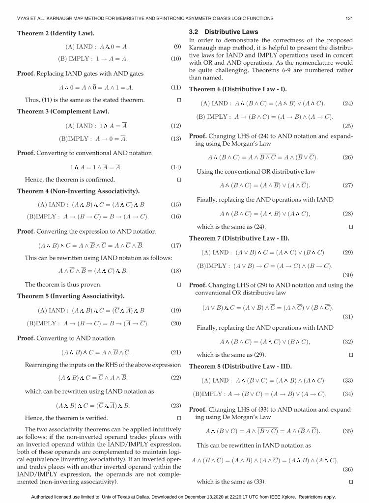
3.2 Distributive Laws
In order to demonstrate the correctness of the proposedKarnaugh map method, it is helpful to present the distribu-tive laws for IAND and IMPLY operations used in concertwith OR and AND operations. As the nomenclature wouldbe quite challenging, Theorems 6-9 are numbered ratherthan named.
Theorem 6 (Distributive Law - I).
ðAÞ IAND : A ðB ^ CÞ ¼ ðA BÞ _ ðA CÞ: (24)
ðBÞ IMPLY : A ! ðB ^ CÞ ¼ ðA ! BÞ ^ ðA ! CÞ:(25)
Proof. Changing LHS of (24) to AND notation and expand-ing using De Morgan’s Law
A ðB ^ CÞ ¼ A ^B ^ C ¼ A ^ ðB _ CÞ: (26)
Using the conventional OR distributive law
A ðB ^ CÞ ¼ ðA ^BÞ _ ðA ^ CÞ: (27)
Finally, replacing the AND operations with IAND
A ðB ^ CÞ ¼ ðA BÞ _ ðA CÞ; (28)
which is the same as (24). tuTheorem 7 (Distributive Law - II).
ðAÞ IAND : ðA _BÞ C ¼ ðA CÞ _ ðB CÞ (29)
ðBÞIMPLY : ðA _BÞ ! C ¼ ðA ! CÞ ^ ðB ! CÞ:(30)
Proof. Changing LHS of (29) to AND notation and using theconventional OR distributive law
ðA _BÞ C ¼ ðA _BÞ ^ C ¼ ðA ^ CÞ _ ðB ^ CÞ:(31)
Finally, replacing the AND operations with IAND
A ðB ^ CÞ ¼ ðA CÞ _ ðB CÞ; (32)
which is the same as (29). tuTheorem 8 (Distributive Law - III).
ðAÞ IAND : A ðB _ CÞ ¼ ðA BÞ ^ ðA CÞ (33)
ðBÞIMPLY : A ! ðB _ CÞ ¼ ðA ! BÞ _ ðA ! CÞ: (34)
Proof. Changing LHS of (33) to AND notation and expand-ing using De Morgan’s Law
A ðB _ CÞ ¼ A ^ ðB _ CÞ ¼ A ^ ðB ^ CÞ: (35)
This can be rewritten in IAND notation as
A ^ ðB ^ CÞ ¼ ðA ^BÞ ^ ðA ^ CÞ ¼ ðA BÞ ^ ðA CÞ;(36)
which is the same as (33). tu
VYAS ET AL.: KARNAUGH MAP METHOD FOR MEMRISTIVE AND SPINTRONIC ASYMMETRIC BASIS LOGIC FUNCTIONS 131
Authorized licensed use limited to: Univ of Texas at Dallas. Downloaded on December 13,2020 at 22:26:17 UTC from IEEE Xplore. Restrictions apply.

Theorem 9 (Distributive Law - IV).
ðAÞ IAND : A _ ðB CÞ ¼ ðA _BÞ ^ ðA _ CÞ (37)
ðBÞ IMPLY : A _ ðB ! CÞ ¼ ðA ! BÞ _ ðA ! CÞ¼ A ! ðB ! CÞ:
(38)
Proof. Changing the LHS of (37) to AND notation and usingthe conventional AND distribution law
A _ ðB CÞ ¼ A _ ðB ^ CÞ ¼ ðA _BÞ ^ ðA _ CÞ: (39)
The above equation validates the theorem. tu
3.3 Canonical Normal Forms for AsymmetricLogic Functions
Conventional Karnaughmaps require that a function be rep-resented as a canonical sum-of-products (SOP) or product-of-sums (POS) in which every literal is present in each termof the function; for the proposed map method for asymmet-ric functions, canonical sum-of-IANDs (SOI) and NAND ofimplications (NOI) representations are used for bilayer ava-lanche spin-diode and stateful memristor logic respectively.
3.3.1 Canonical Forms for IAND-OR Logic Set
The IAND and OR functions are the basis logic functionsavailable with bilayer avalanche spin-diode logic. Similar tocanonical SOP and POS expressions, canonical SOI expres-sions can be developed from non-canonical SOI expressionsby adding the literalsmissing from each term.Applying The-orem 2, appending an IAND operation of a null-valued(zero) expression (such as A ^A) enables the expansionwithout modifying the logical value of the expression. Tak-ing the non-canonical SOI expression
fsoi ¼ ððB CÞ DÞ _ ððA BÞ CÞ: (40)
A ^A andD ^D can be appended to the two terms, resulting in
fsoi ¼ fððB CÞ DÞ ðA ^AÞg _ fððA BÞ CÞ ðD ^DÞg:(41)
Using Theorem 6 (A)
fsoi ¼ fððB CÞ DÞ Ag _ fððB CÞ DÞ Ag_ fððA BÞ CÞ Dg _ fððA BÞ CÞ Dg: (42)
Rearranging the inverted and non-inverted inputs accord-ing to Theorem 5 (A)
fsoi ¼ fððA BÞ CÞ Dg _ fððA BÞ CÞ Dg_ fððA BÞ CÞ Dg _ fððA BÞ CÞ Dg: (43)
Finally, by conventional OR idempotency, A _A ¼ A
fsoi ¼ fððA BÞ CÞ Dg _ fððA BÞ CÞ Dg_fððA BÞ CÞ Dg: (44)
The above expression is a canonical SOI expression. Ingeneral, canonical IAND-of-sums (IOS) expressions can beachieved with the same method as canonical POS: by OR-ing
a null expression of the missing literals with each of the sum-terms, followed by ordinary Boolean algebraic simplification.
3.3.2 Canonical Forms for IMPLY-NAND Logic Set
A given Boolean expression may not be in its canonical form,and thus similar to the methodology adopted for IANDs,canonical NOI expressions can be developed from non-canonical NOI expressions by inserting the literals missingfrom each termwhile maintaining logical equivalence. State-ful memristor logic provides IMPLY and NAND operationsas the basis logic set. Performing an IMPLY operation of aunity ‘1’-valued expression (such as A _A), followed byBoolean reduction as per the identities in the previous sec-tion, expands the function into a canonical formwhile retain-ing its logical value as per Theorem 2 (B). Consider the non-canonical NOI expression in (45)
fnoi ¼ ðB ! ðC ! DÞÞ ^ ðA ! ðB ! CÞÞ: (45)
A _A andD _D can be appended to the two terms, resultingin
fnoi ¼ fðA _AÞ ! ðB ! ðC ! DÞÞg^ fðD _DÞ ! ðA ! ðB ! CÞÞg:
(46)
Using Theorem 7 (B)
fnoi ¼ fA ! ðB ! ðC ! DÞÞg^fA ! ðB ! ðC ! DÞÞg ^ fD ! ðA ! ðB ! CÞÞg
^fD ! ðA ! ðB ! CÞÞg:(47)
Rearranging the inverted and non-inverted inputs accord-ing to Theorems 4(B) and 5(B)
fnoi ¼ fA ! ðB ! ðC ! DÞÞg^fA ! ðB ! ðC ! DÞÞg ^ fA ! ðB ! ðC ! DÞÞg
^fA ! ðB ! ðC ! DÞÞg:(48)
The above expression is a canonical NOI expression. In gen-eral, canonical Implication-of-NANDs (ION) expressionscan be achieved with the same method as canonical POS: byAND-ing a unity expression of the missing literals with eachof the sum-terms, followed by ordinary Boolean algebraicsimplification.
4 KARNAUGH MAP METHOD FOR ASYMMETRIC
LOGIC FUNCTIONS
The proposed Karnaugh map method enables a graphicaltechnique for the minimization of memristor and spintroniclogic with asymmetric basis functions. Following the expla-nation of conventional Karnaugh maps below, the adaptedKarnaugh map method is described and its operation isexplained. The translation between stateful memristor logicand bilayer avalanche spin-diode logic is shown, followedby examples that provide instruction as to the use of theproposed method.
132 IEEE TRANSACTIONS ON COMPUTERS, VOL. 70, NO. 1, JANUARY 2021
Authorized licensed use limited to: Univ of Texas at Dallas. Downloaded on December 13,2020 at 22:26:17 UTC from IEEE Xplore. Restrictions apply.

4.1 Background: Conventional Karnaugh Maps
Karnaugh Maps are tabular representations of Boolean logicfunctions consisting of 2n cells, each for one among the possi-ble combinations of n-bit binary data. The cells are arrangedsuch that logically adjacent terms share physical adjacency.Graphical pairing of these adjacent terms reduces the functionto its essential prime implicants [1], [26]. Whereas Karnaughoriginally described the method only through examples [1],this paper endeavors to formally demonstrate the validity ofthe proposedmethod.
A conventional Karnaugh map is shown in Fig. 4 for theexpression
fsop ¼ ðA ^B ^ CÞ _ ðA ^B ^ CÞ _ ðA ^B ^ CÞ: (49)
This expression can be rewritten by duplicating the termA ^B ^ C
fsop ¼ fðA ^B ^ CÞ _ ðA ^B ^ CÞg _ fðA ^B ^ CÞ _ ðA ^B ^ CÞg:(50)
This expression can then be simplified according to conven-tional Boolean algebra techniques, first with the OR distrib-utive law
fsop ¼ ððA _AÞ ^B ^ CÞ _ ððB _BÞ ^A ^ CÞ: (51)
A _A and B _B are 010 by complement law, enabling theelimination of operands A and B from the respective productterms
fsop ¼ ð1 ^B ^ CÞ _ ð1 ^A ^ CÞ ¼ ðB ^ CÞ _ ðA ^ CÞ:(52)
Karnaugh’s method reaches this result in a similar man-ner, but graphically. This can be noted in the Karnaugh mappair encircledwith green and orange (Fig. 4): The logical adja-cency enables the combination of literals with their comple-ments and thereforeminimize redundancies in a function.
4.2 Map Method for Asymmetric Functions
The proposed map method for asymmetric logic functionsis performed in the following step-wise manner:
1. Transform the target expression into its canonicalform (i.e., SOI/IOS or NOI/ION).
2. Mark the corresponding SOI/NOI terms in the cellsof a Karnaugh map.
3. Group theminterms/maxterms graphically accordingto the standard Karnaugh map techniques describedin [1].
4. Use the standard rules of the Karnaughmap to createthe expressionwith the resultant terms.
5. Unless the left-most (right-most) operand is equalto the left-most (right-most) operand in an IAND(IMPLY) equation’s canonical form, it should becomplemented.
To illustrate this method, the equation displayed in theK-map in Fig. 4 will be reused. In this four-bit function, theorder of the variables are fA;B;C;Dg, meaning that any ofthe variables fB;C;Dg must be inverted if they are the left-most operand in the simplified equation. The following sys-tematic evaluation of the equation will highlight the neces-sity of the fifth step
fsoi ¼ ððA BÞ CÞ _ ððA BÞ CÞ _ ððA BÞ CÞ: (53)
This expression can be simplified by applying the theoremsoutlined in Section 3.1. First using Theorem 7(A) twice insuccession gives (54) and (55)
fsoi ¼ ðððA BÞ _ ðA BÞÞ CÞ _ ððA BÞ CÞ (54)
fsoi ¼ ðððA _AÞ BÞ CÞ _ ððA BÞ CÞ: (55)
A _A is unity due to the OR complement law, and 1 B ¼ Baccording to Theorem 3(A). Thus
fsoi ¼ ðð1 BÞ CÞ_ððA BÞ CÞ ¼ ðB CÞ_ððA BÞ CÞ:(56)
Due to the nature of the complement law for IAND, read-ing the same K-map will yield different results even whenthe pairings stay constant. For conventional logic, 1 ^B ¼ B,although for the IAND, 1 B ¼ B. Due to this discrepancy,it is necessary to complement B in the final equation, in orderto maintain logical equivalence. The expression can be fur-ther reduced by applying Theorems 6(A) and 9(A)
fsoi ¼ ðB _ ðA BÞÞ C (57)
fsoi ¼ ððB _AÞ ^ ðB _BÞÞ C: (58)
With the conventional OR complement law, and B _B ¼ 1using Theorem 7(A), this becomes
fsoi ¼ ðB CÞ _ ðA CÞ: (59)
The same result is obtained by applying the proposed meth-odology to the Karnaugh map in Fig. 4.
Now consider the SOI expression in (53) represented as acanonical NOI in (60)
fnoi ¼ ðA ! ðB ! CÞÞ ^ ðA ! ðB ! CÞÞ^ ðA ! ðB ! CÞÞ:
(60)
Similar to SOI, the above expression can be reduced usingthe proposed Boolean laws for IMPLY logic (Section 3)
fnoi ¼ ðB ! CÞ ^ ðA ! CÞ: (61)
Expression (61) shows the minimized form of (60). Now,applying the modified Karnaugh method proposed in thissection to the expression in (60) (Karnaugh map shown inFig. 4), we obtain
fnoi ¼ ðB ! CÞ ^ ðA ! CÞ: (62)
Fig. 4. Karnaugh map for the example in Section 4.1 (49) and the twoexamples in Section 4.2 (53) and (60).
VYAS ET AL.: KARNAUGH MAP METHOD FOR MEMRISTIVE AND SPINTRONIC ASYMMETRIC BASIS LOGIC FUNCTIONS 133
Authorized licensed use limited to: Univ of Texas at Dallas. Downloaded on December 13,2020 at 22:26:17 UTC from IEEE Xplore. Restrictions apply.

Note that complementation is not required in this instance,as none of the inverted inputs appear as the left-most oper-and in the reduced equation. Hence, (61) and (62) illustratethat the proposed method is valid for NOI as well.
4.3 Examples
To clearly explain the mapping methodology, we demon-strate the application of Karnaughmaps to the decompositionof a few sample Boolean expressions involving IAND-ORand IMPLY-NAND logic sets. The result for each examplecan be validated by converting and solving them as SOP. Pos-sible circuit implementations have also been shown for eachexample.
Example 1. (Three-Variable SOI). Consider the followingSOI:
fsoi ¼ fððA BÞ CÞ _ ððA BÞ CÞ _ ððA BÞ CÞ_ððA BÞ CÞ _ ððA BÞ CÞg:
(63)Converting to conventional SOP
fsop ¼ fðA ^B ^ CÞ _ ðA ^B ^ CÞ _ ðA ^B ^ CÞ_ðA ^B ^ CÞ _ ðA ^B ^ CÞg: (64)
Grouping the terms and applying the conventional ORcomplement law successively
fsop ¼ C _ ðA ^B ^ CÞ: (65)
Using the AND distributive law and OR ComplementLaw in succession
fsop ¼ ðC _A ^BÞ ^ ðC _ CÞ (66)
fsop ¼ C _ ðA ^BÞ; (67)
which can be rewritten as SOI
fsoiðA;B;CÞ ¼ C _ ðA BÞ: (68)
The same result is obtained by interpreting the Karnaughmap in Fig. 5a, hence validating the proposed method.Fig. 5b shows the device-level implementation for (68).
Example 2. (Four-Variable SOI). The following SOI expres-sion is plotted in the Karnaugh map of Fig. 6a
fsoi ¼ ðððA BÞ CÞ DÞ _ ðððA BÞ CÞ DÞ_ ðððA BÞ CÞ DÞ _ ðððA BÞ CÞ DÞ_ ðððA BÞ CÞ DÞ _ ðððA BÞ CÞ DÞ
_ ðððA BÞ CÞ DÞ:
(69)
The corresponding simplified function deduced by apply-ing the mapping method outlined in Section 4.2 is givenby (70). Note that literal B in the second and third IANDterms has been inverted
fsoi ¼ ððA BÞ CÞ _ ððB CÞ DÞ _ ðB CÞ: (70)
Gate-level circuit implementation using IAND and ORgates is shown in Fig. 6b.
Example 3. (Three-Variable NOI). This example illustratesthe optimization of an NOI expression and its implemen-tation using the IMPLY-NAND logic set (Fig. 7). For anal-ogy, consider the function in (63), now represented as anNOI (note that (63) and (71) are not equivalent) and plot-ted on a Karnaugh map as shown in Fig. 7a
fnoi ¼ fðA ! ðB ! CÞÞ ^ ðA ! ðB ! CÞÞ^ðA ! ðB ! CÞÞ ^ ðA ! ðB ! CÞÞ^ðA ! ðB ! CÞÞg:
(71)
Using the proposed mapping method, non-invertedinput B is complemented and the simplified function iswritten as
fnoi ¼ C ^ ðA ! BÞ: (72)
Fig. 7b shows a possible memristor circuit for the IMPLY-NAND implementation. Here, complementary repre-sentation [13] is used and the function can be reached
Fig. 5. (a) Karnaugh map and (b) minimized physical circuit for Exam-ple 4.3.
Fig. 6. (a) Karnaugh map and (b) minimized schematic for Example 4.3.
134 IEEE TRANSACTIONS ON COMPUTERS, VOL. 70, NO. 1, JANUARY 2021
Authorized licensed use limited to: Univ of Texas at Dallas. Downloaded on December 13,2020 at 22:26:17 UTC from IEEE Xplore. Restrictions apply.

step-wise by executing the computational sequence listedin Table 3 [13].
Example 4. (Incompletely-Specified Four-Variable NOI).Expression (73) shows a Boolean function represented asan NOI with a “don’t care” term. Fig. 8a shows the Kar-naugh map and reduced groupings of
fnoi ¼ fðA ! ðB ! ðC ! DÞÞÞ ^ ðA ! ðB ! ðC ! DÞÞÞ^ðA ! ðB ! ðC ! DÞÞÞ ^ ðA ! ðB ! ðC ! DÞÞÞ
^ ðA ! ðB ! ðC ! DÞÞÞ ^ ðA ! ðB ! ðC ! DÞÞÞdg:(73)
The above expression is reduced to (74) by following theproposed mapping process. In this case, the literal C iscomplemented in both of the terms in accordance with thesteps of the proposed map method. Therefore, the mini-mized function is
fnoi ¼ ðB ! CÞ ^ ðA ! ðB ! CÞÞ: (74)
Fig. 8b shows a memristive circuit with complemen-tary representation for the implementation of (74). Table 4shows the minimized sequence of operations that leadsto the desired result being stored in the memristor R2.
5 ALGORITHMICALLY-DESIGNED MEMRISTOR
FULL ADDER
To demonstrate its utility, this novel Karnaughmap approachis applied to the memristor full adder composed of IMPLYand NAND gates. The equations for the sum and carry-out ofthe full adder are reduced separately, with each having theirown Karnaughmap. This Karnaughmapmethod algorithmi-cally designs a full adder circuit that reduces the requirednumber of steps by 28 percent.
The Karnaugh maps for the sum and carry-out are firstdetermined from Table 5, with the sum equation resultingin (75) and the carry out equation resulting in (76).
fnoi ¼ fðA ! ðB ! CÞÞ ^ ðA ! ðB ! CÞÞ^ðA ! ðB ! CÞÞ ^ ðA ! ðB ! CÞÞg
(75)
Fig. 7. Example 4.3: (a) Karnaugh map for (71). (b) Memristor circuit forIMPLY-NAND implementation of (72), where memristors A, B, and Ccontain the input values, while R1 and R2 are output memristors.
TABLE 3Computational Steps for Implementation of (72)
Using Stateful Memristive IMPLY Logic
Step Operation VCOND
applied toVSET
applied toVRESET
applied toOutput
MemristorResult
0 RESET - - R1; R2 - R1 ¼ R2 ¼ 01 B ! R2 B R2 - R2 B2 A ! R2 A R2 - R2 A ! B3 R2 ! R1 R2 R1 - R1 ðA ! BÞ4 C ! R2 C R2 - R2 Expression
(72)
Fig. 8. (a) Karnaugh map for (73). (b) Memristor circuit for IMPLY-NANDimplementation of (74), where memristors A, B;B, C, and C contain theinput values, while R1 and R2 are output memristors.
TABLE 4Computational Steps for Implementation of (74)
Using Stateful Memristive IMPLY Logic
Step OperationVCOND
appliedto
VSET
appliedto
VRESET
appliedto
OutputMemristor
Result
0 RESET - - R1; R2 - R1 ¼ R2 ¼ 01 C ! R2 C R2 - R2 C2 B ! R2 B R2 - R2 B ! C3 R2 ! R1 R2 R1 - R1 ðB ! CÞ4 R2 ¼ 0 - - R2 - -5 C ! R2 C R2 - R2 C6 B ! R2 B R2 - R2 B ! C7 A ! R2 A R2 - R2 A ! ðB ! CÞ8 R2 ! R1 R2 R1 - R1 Expression
(74)
VYAS ET AL.: KARNAUGH MAP METHOD FOR MEMRISTIVE AND SPINTRONIC ASYMMETRIC BASIS LOGIC FUNCTIONS 135
Authorized licensed use limited to: Univ of Texas at Dallas. Downloaded on December 13,2020 at 22:26:17 UTC from IEEE Xplore. Restrictions apply.

fnoi ¼ fðA ! ðB ! CÞÞ ^ ðA ! ðB ! CÞÞ^ðA ! ðB ! CÞÞ ^ ðA ! ðB ! CÞÞg:
(76)
The two equations are mapped using the method describedin [1], with the resulting K-maps shown in Fig. 9. As the Kar-naughmap for the sum of the full adder contains only single-tons, no further reduction is possible. The equation for theIMPLY-NAND full adder sum can be directly derivedfrom the Karnaugh map, using the methods discussed inSection 4.2. In the case of the carry-out, some coverage can beachieved using the traditional Karnaughmap grouping tech-niques from [1], allowing further reduction of the equation.The reduced equation may be derived in NOI form fromthe Karnaugh map, following the steps in Section 4.2. Thereduced carry-out equation is
fnoi ¼ ðA ! CÞ ^ ðB ! CÞ ^ ðA ! BÞ: (77)
Note that the second operand in each term has been inverted,as none of those operands are equal to the right-most oper-and in the IMPLY equation’s canonical form.
The resulting fully-reduced logical step-wise procedure isdepicted in Fig. 10. This algorithmically-designed full adderrequires seven steps for the carry-out computation and 14steps for the sum computation, for a total of 21 total steps.This is a 28 percent reduction from the state-of-the-art [7],which was optimizedmanually. As manual approaches gen-erally outperform algorithmic procedures for small-scale cir-cuit optimization, this significant improvement is quiteremarkable. Furthermore, it should be noted that while thealgorithmically-designed full adder requires a larger device
count, the number of steps is far more important when con-sidering the efficiency of the complete stateful memristorlogic system [27].
The 28 percent reduction in step count is specific to the one-bit full adder, but can be scaled up to multi-bit full adders.Therefore, for an N-bit full adder, the K-map-optimized cir-cuit requires 14N and 7N steps to implement Sum and Cout,respectively, retaining the 28 percent step reduction formulti-bit adders. Furthermore, if Sum andCout are computed in par-allel, Sum requires 7N + 7 steps while Cout requires 7N steps,boosting the overall step reduction to 76 percent. The pro-posed method thus has the potential to achieve step reduc-tions greater than 28 percentwhen applied to large systems.
6 CONCLUSION
The logic minimization method proposed here enables thedirect mapping of memristive and spintronic logic functionsonto Karnaugh maps, which has been shown in the past to bea valuable first step in creating logic manipulation techniquesfor novel devices with unconventional logic functions. Thismethod is tailored to the asymmetric IMPLY and IAND logicfunctions, and the NAND and OR functions that are alsoefficiently performed by memristors and bilayer avalanchespin-diodes, respectively. The identities defined here enablealgebraicmanipulation of these functions,which is used to for-mally demonstrate the validity of the proposed logic minimi-zation technique. This logic minimization technique providesa foundation for logic reduction based on memristorsand spintronic logic, as well as a template for logic minimiza-tion with alternative beyond-CMOS computing structures.Furthermore, algorithmic design using this Karnaugh map
TABLE 5Truth Table for a Full Adder
A B Cin Cout Sum
0 0 0 0 00 0 1 0 10 1 0 0 10 1 1 1 01 0 0 0 11 0 1 1 01 1 0 1 01 1 1 1 1
Fig. 9. Karnaugh maps for the full adder equations. Values have beenmapped directly from the truth table. (a) Karnaugh map for (75). (b) Kar-naugh map for (76).
Fig. 10. Logical abstractions for each equation. Input variables are desig-nated with circles, IMPLY operations are designated with trapezoids, andNAND operations are designated with rectangles. (a) Logical abstractionfor (75). (b) Logical abstraction for the reducedCout Equation (77).
136 IEEE TRANSACTIONS ON COMPUTERS, VOL. 70, NO. 1, JANUARY 2021
Authorized licensed use limited to: Univ of Texas at Dallas. Downloaded on December 13,2020 at 22:26:17 UTC from IEEE Xplore. Restrictions apply.

method has been shown to provide a 28 percent reduction instep count as compared to the best manually-minimized fulladder circuits. This Karnaugh map method adapted to non-commutative logic functions thus constitutes an importantstep toward the development of logicminimization techniquesfor the next generation of computing.
REFERENCES
[1] M. Karnaugh, “The map method for synthesis of combinationallogic circuits,” Trans. Amer. Inst. Elect. Engineers, Part I: Commun.Electron., vol. 72, no. 5, pp. 593–599, Nov. 1953.
[2] M. T. Niemier et al., “Nanomagnet logic: Progress toward system-level integration,” J. Phys., Condens. Matter, vol. 23, no. 49, 2011,Art. no. 493202.
[3] D. Hampel and R. O. Winder, “Threshold logic,” IEEE Spectr.,vol. 8, no. 5, pp. 32–39, May 1971.
[4] A. Imre,“Majority logic gate for magnetic quantum-dot cellularautomata,” Science, vol. 311, no. 5758, pp. 205–208, 2006.
[5] J. S. Friedman, E. R. Fadel, B. W. Wessels, D. Querlioz, andA. V. Sahakian, “Bilayer avalanche spin-diode logic,” AIP Advances,vol. 5, no. 11, 2015, Art. no. 117102.
[6] J. S. Friedman et al., “Cascaded spintronic logic with low-dimen-sional carbon,”Nat. Commun., vol. 8, 2017, Art. no. 15635.
[7] S. Kvatinsky, G. Satat, N. Wald, E. G. Friedman, A. Kolodny, andU. C. Weiser, “Memristor-based material implication (IMPLY)logic: Design principles and methodologies,” IEEE Trans. VeryLarge Scale Integr. (VLSI) Syst., vol. 22, no. 10, pp. 2054–2066,Oct. 2014.
[8] E. Lehtonen and M. Laiho, “Stateful implication logic with mem-ristors,” in Proc. IEEE/ACM Int. Symp. Nanoscale Archit., 2009,pp. 33–36.
[9] D. E. Nikonov, G. I. Bourianoff, and T. Ghani, “Proposal of a spintorque majority gate logic,” IEEE Electron Device Lett., vol. 32,no. 8, pp. 1128–1130, Aug. 2011.
[10] M. H. Ben-Jamaa, K. Mohanram, and G. De Micheli, “An efficientgate library for ambipolar CNTFET logic,” IEEE Trans. Comput.-Aided Design Integr. Circuits Syst., vol. 30, no. 2, pp. 242–255,Feb. 2011.
[11] H. Zhang, W. Kang, L. Wang, K. L. Wang, and W. Zhao, “Statefulreconfigurable logic via a single-voltage-gated spin hall-effectdriven magnetic tunnel junction in a spintronic memory,” IEEETrans. Electron Devices, vol. 64, no. 10, pp. 4295–4301, Oct. 2017.
[12] H. Zhang, W. Kang, K. Cao, B. Wu, Y. Zhang, and W. Zhao,“Spintronic processing unit in spin transfer torque magnetic ran-dom access memory,” IEEE Trans. Electron Devices, vol. 66, no. 4,pp. 2017–2022, Apr. 2019.
[13] E. Lehtonen, J. Poikonen, and M. Laiho, “Implication logic synthe-sis methods for memristors,” in Proc. IEEE Int. Symp. CircuitsSyst., 2012, pp. 2441–2444.
[14] A. Chattopadhyay and Z. Rakosi, “Combinational logic synthesisfor material implication,” in Proc. IEEE/IFIP 19th Int. Conf. VLSISyst.-on-Chip, 2011, pp. 200–203.
[15] A. Raghuvanshi and M. Perkowski, “Logic synthesis and a gener-alized notation for memristor-realized material implicationgates,” in Proc. IEEE/ACM Int. Conf. Comput.-Aided Des., 2014,pp. 470–477.
[16] S. Shirinzadeh, M. Soeken, and R. Drechsler, “Multi-objective BDDoptimization for RRAM based circuit design,” in Proc. IEEE 19th Int.Symp. Des. Diagnostics Electron. Circuits Syst., 2016, pp. 1–6.
[17] F. S. Marranghello, V. Callegaro, A. I. Reis, and R. P. Ribas, “SOPbased logic synthesis for memristive IMPLY stateful logic,” inProc. 33rd IEEE Int. Conf. Comput. Des., 2015, pp. 228–235.
[18] F. Lalchhandama, B. G. Sapui, and K. Datta, “An improvedapproach for the synthesis of Boolean functions using memristorbased IMPLY and INVERSE-IMPLY gates,” in Proc. IEEE Comput.Soc. Annu. Symp. VLSI, 2016, pp. 319–324.
[19] S. Chakraborti, P. V. Chowdhary, K. Datta, and I. Sengupta, “BDDbased synthesis of boolean functions using memristors,” in Proc.9th Int. Des. Test Symp., 2014, pp. 136–141.
[20] D. Fan, M. Sharad, and K. Roy, “Design and synthesis of ultralowenergy spin-memristor threshold logic,” IEEE Trans. Nanotechnol.,vol. 13, no. 3, pp. 574–583, May 2014.
[21] S.-A. Wang, C.-Y. Lu, I.-M. Tsai, and S.-Y. Kuo, “Modified kar-naugh map for quantum Boolean circuits construction,” in Proc.3rd IEEE Conf. Nanotechnol., 2003, pp. 651–654.
[22] L. Chua, “Memristor-the missing circuit element,” IEEE Trans.Circuit Theory, vol. 18, no. 5, pp. 507–519, Sep. 1971.
[23] D. B. Strukov, G. S. Snider, D. R. Stewart, andR. S. Williams,“Themissing memristor found,” Nature, vol. 453, no. 7191, pp. 80–83,2008.
[24] Y. Yang, P. Gao, S. Gaba, T. Chang, X. Pan, and W. Lu,“Observation of conducting filament growth in nanoscale resistivememories,” Nat. Commun., vol. 3, 2012, Art. no. 732.
[25] J. Borghetti, G. S. Snider, P. J. Kuekes, J. J. Yang, D. R. Stewart,and R. S. Williams,“’Memristive’ switches enable ’stateful’ logicoperations via material implication,” Nature, vol. 464, no. 7290,pp. 873–876, 2010.
[26] J. F. Miller, “Principles in the evolutionary design of digital cir-cuits - Part I,” Genetic Program. Evolvable Mach., vol. 1, pp. 7–35,2000.
[27] X. Hu, M. J. Schultis, M. Kramer, A. Bagla, A. Shetty, andJ. S. Friedman, “Overhead requirements for stateful memristor log-ic,” IEEE Trans. Circuits Syst. I, Reg. Papers, vol. 66, no. 1, pp. 263–273,Jan. 2019.
Vaibhav Vyas received the BE degree in electron-ics and communication engineering from the RajivGandhi Proudyogiki Vishwavidyalaya (R.G.P.V.)University, Bhopal, Madhya Pradesh, India, in2016, and the MS degree in electrical engineeringfrom the Erik Jonsson School of Engineering &Computer Science, University of Texas at Dallas,Richardson, Texas, in 2018. He continues to doresearch on circuit design and logic design automa-tion for bilayer avalanche spin-diode logic andstateful memristor logic. After graduating from UT
Dallas, he was working with John Deere Intelligent Solutions Group, DesMoines (IA) as an embedded software engineer with the Precision AgDepartment. In the September of 2019, he joined the Firmware Engineer-ing Team, Extron Electronics, working on a variety of Extron products.
Lucian Jiang-Wei received the BS degree incomputer science from the Erik Jonsson Schoolof Engineering & Computer Science, Universityof Texas at Dallas, Richardson, Texas, in 2019.He continues to do research on logic design auto-mation for spintronic and emerging technologies.
Peng Zhou (Student Member, IEEE) receivedthe bachelor’s degree in mechanical engineeringfrom the Xiamen University of Technology, Xia-men, China, in 2015, and the master’s degree inelectrical engineering from Xiamen University,Xiamen, China, in 2018. He is working toward thePhD degree in electrical engineering in the ErikJonsson School of Engineering & Computer Sci-ence, University of Texas at Dallas, Richardson,Texas. His current research focus is on neurmor-phic computing with STT-MRAM.
VYAS ET AL.: KARNAUGH MAP METHOD FOR MEMRISTIVE AND SPINTRONIC ASYMMETRIC BASIS LOGIC FUNCTIONS 137
Authorized licensed use limited to: Univ of Texas at Dallas. Downloaded on December 13,2020 at 22:26:17 UTC from IEEE Xplore. Restrictions apply.
Xuan Hu (Student Member, IEEE) received theBS degree in electrical and information engineer-ing from Huaqiao University, Xiamen, China, in2013, and the MS degree in electrical engineeringfrom Arizona State University, Tempe, Arizona, in2015. He is currently working toward the PhDdegree in electrical engineering in the Erik Jons-son School of Engineering & Computer Science,University of Texas at Dallas, Richardson, Texas.His current research focus is on circuit designand modeling of efficient memristive, spintronic,and carbon nanotube logic circuits.
Joseph S. Friedman (Senior Member, IEEE)received the AB and BE degrees from DartmouthCollege, Hanover, New Hampshire, in 2009, andthe MS and PhD degrees in electrical & computerengineering from Northwestern University, Evan-ston, Illinois, in 2010 and 2014, respectively. Hejoined the University of Texas at Dallas, Richard-son, Texas, in 2016, where he is currently anassistant professor of electrical & computer engi-neering and the director of the NeuroSpinCom-pute Laboratory. From 2014 to 2016, he was a
Centre National de la Recherche Scientifique research associate withthe Institut d’Electronique Fondamentale, Universit�e Paris-Sud, Orsay,France. He has also been a summer faculty fellow with the U.S. AirForce Research Laboratory, Rome, New York, a visiting professor withPolitecnico di Torino, Turin, Italy, a guest scientist with RWTH AachenUniversity, Aachen, Germany, and worked on logic design automationas an intern with Intel Corporation, Santa Clara, California. He is a mem-ber of the editorial board of the Microelectronics Journal, the technicalprogram committees of DAC, DATE, SPIE Spintronics, NANOARCH,GLSVSI, ICECS, VLSI-SoC, the review committee of ISCAS, and theIEEE Circuits & Systems Society Nanoelectronics and Gigascale Sys-tems Technical Committee. He has been a member of the organizingcommittee of VLSI-SoC 2020, NANOARCH 2019, and DCAS 2018. Hehas also been awarded a Fulbright Postdoctoral Fellowship. Hisresearch interests include the invention and design of novel logical andneuromorphic computing paradigms based on nanoscale and quantummechanical phenomena, with particular emphasis on spintronics.
" For more information on this or any other computing topic,please visit our Digital Library at www.computer.org/csdl.
138 IEEE TRANSACTIONS ON COMPUTERS, VOL. 70, NO. 1, JANUARY 2021
Authorized licensed use limited to: Univ of Texas at Dallas. Downloaded on December 13,2020 at 22:26:17 UTC from IEEE Xplore. Restrictions apply.