SPECIFICATION FOR 11 kV OUTDOOR POLE-MOUNTED …
26
DAKSHIN HARYANA BIJLI VITRAN NIGAM Office of the Chief General Manager/P&D, Vidyut Sadan, Vidyut Nagar, Hisar-125005 Tel: 01662-221285, 221830 (GM/P&D) Fax: 01662-220481 Specification No.- S-190/DD-177/2008 TECHNICAL SPECIFICATIONS FOR 11 kV OUTDOOR POLE-MOUNTED AUTO-RECLOSE WITH INTEGRATED REMOTE COMMUNICATION CAPABILITIES Chief General Manager/P&D, DHBVN, Hisar Issue of the Month: April 2008 1
Transcript of SPECIFICATION FOR 11 kV OUTDOOR POLE-MOUNTED …

DAKSHIN HARYANA BIJLI VITRAN NIGAM Office of the Chief General Manager/P&D,
Vidyut Sadan, Vidyut Nagar, Hisar-125005
Tel: 01662-221285, 221830 (GM/P&D) Fax: 01662-220481
Specification No.- S-190/DD-177/2008
TECHNICAL SPECIFICATIONS
FOR 11 kV OUTDOOR POLE-MOUNTED
AUTO-RECLOSE WITH
INTEGRATED REMOTE COMMUNICATION CAPABILITIES
Chief General Manager/P&D, DHBVN, Hisar
Issue of the Month: April 2008
1

2
1. SCOPE This specification covers requirements for outdoor Pole-mounted auto-reclosers that have programmable protection features and integrated remote operation capability and that are intended for source and down-line duty on rural distribution networks at nominal A.C. voltages of 11 kV.
A primary objective of this specification is to foster modularity and a maximum level of interchangeability and integration to a central SCADA system by supporting IEC60870-5-101 communications protocol
2. NORMATIVE REFERENCES The following standards contain provisions that, through reference in the text, constitute requirements of this specification at the time of publication the revisions indicated were valid. All standards are subject to review and parties to purchasing agreements based on this specification are encouraged to investigate the possibility of applying the most recent revisions of the standards listed below. ANSI/IEEE C37.60-1981: Requirements for overhead, pad mounted, dry vault, and submersible automatic circuit reclosers and fault interrupters for AC systems (RI993) IEC 60255, Electrical relays IEC 60056:1987, High-voltage alternating-current circuit breakers. Amendment No. 1:1 992. IEC 60529:1989, Degrees of protection provided by enclosures (IP Code). UNIPEDE NORM (SPEC) 13 (1995): Automation and Control Apparatus for Generating Stations and Substations: Electromagnetic Compatibility Immunity Requirements.
3. CLIMATIC CONDITIONS The Substation shall be suitable for satisfactorily working under the following climatic conditions: - Max. Ambient Temperature 700 C Min. Ambient Temperature - 50 C Max. Relative Humidity 100 % Min. Relative Humidity 26 % Altitude Below 1000 meters above mean sea
level. The Auto-reclosers used shall be suitably designed and treated for normal life and satisfactory operation under the hot and hazardous tropical climate conditions and shall be dust and vermin proof. All interior and exterior ferrous surfaces of auto-reclosers and control cabinets shall be manufactured from marine grade (rust free) stainless steel. All support structures and associated bolts and nuts with these parts, shall be hot-dip galvanized.
3
4. DEFINITIONS AND ABBREVIATIONS 4.1. Auto-recloser (AR): A mechanical switching device that, after opening,
closes automatically after a predetermined time. Several reclosures could occur before lockout.
4.2. Cold load pick-up (CLP) feature: A feature that allows modification of the over-current protection characteristics in order to prevent relay maloperation under conditions of system energisation.
4.3. Dead time: The time between the instant that the current is interrupted by the AR and the instant the contact of the AR closes as a result of an automatic reclose operation. [IEC 50-448-04-09]
4.4. Definite time lag (DTL) protection element: A protection element with a settable time delay that is constant above the pick-up current setting.
4.5. Delayed protection operation: The protection functionality enabling delayed circuit-breaker operation, whether this is due to an IDMTL or DTL protection element.
4.6. Disc reset time: The time required for the disc of an electromechanical IDMTL protection relay to turn back to its original position after it has turned to the position where a protection operation was initiated.
4.7. Effectively earthed system: An earthed system in which the healthy phase power frequency phase-to-earth over voltages associated with earth faults are limited to 80% of the highest phase-to-phase voltage of the system.
4.8. Fast curve protection element: A family of curves with operating times approximately constant (slightly inverse) relative to the multiple of pick-up setting.
4.9. Instantaneous protection element: An element with no intentional time delay active above a pre-determined pick-up current setting.
4.10. Inverse definite minimum time (IDMT) protection element: A protection element the minimum operating time of which is adjustable and is inversely proportional to the fault current.
4.11. Pole-mounted remote terminal unit (PMRTU): A remote terminal unit that is designed for pole mounting and that operates specific pole-mounted equipment remotely.
4.12. Rapid protection operation: The protection functionality enabling rapid circuit-breaker operation, whether this is due to an instantaneous, fast curve, or a definite time delay protection element with relatively short definite time delay.
4.13. Reset time: The time duration after a circuit-breaker close operation for which the measured currents are below a fault detecting level. On the expiry of this time the protection sequence resets.
4.14. Secure control: A single mechanically non-latching switch that effects one state of a control function only. An example of which is either a non-latching switch or two separate push buttons that effect one state of a control function
4
only in each position. If a control is activated repeatedly it only effects that state and does not change the state of the control.
4.15. Sensitive earth fault (SEF) relay: A relay that is sensitive to very low earth fault currents and in which the operating settings are for current magnitude and definite time delay.
4.16. Supervisory: Remote control and indications of an AR or a PMRTU by means of a telecommunications link.
4.17. Toggled control: A single mechanically non-latching switch/push-button that enables a single control function on the first operation of the switch/push-button and disables the function on the second operation of the same switch/push button.
4.18. Zone sequence co-ordination (ZSC): The feature that allows protection devices to maintain sequence co-ordination for combinations of rapid and delayed protection operations.
5. REQUIREMENTS 5.1. General
The AR shall be suitable for use on non-effectively earthed and effectively earthed networks and under the system conditions and service conditions as follows: 5.1.1. Nominal system voltage (U,) (r.m.s.) - 11 kV; 5.1.2. Maximum system voltage (Um) (r.m.s.) - 15.5 kV; 5.1.3. Load current - 630 A; 5.1.4. Short circuit-breaking capacity - 12.5 kA; 5.1.5. LIWV - 110 kV 5.1.6. System frequency - 5O Hz+1.5; 5.1.7. Number of phases - 3; 5.1.8. Interrupting medium - Vacuum 5.1.9. Insulation medium -Solid Dielectric 5.1.10. Closing Mechanism - Magnetic Actuator 5.1.11. Opening Mechanism - Magnetic Actuator 5.1.12. Mechnical Operation(Minimum) - 10,000 5.1.13. Full load Operation(Minimum) - 10,000
5.2. Mounting 5.2.1. The AR shall be suitable for single pole mounting. 5.2.2. Adequately rated lifting eyes shall be provided and they shall be
designed to allow the completely assembled AR (surge arresters fitted) to be lifted without recourse to a sling spreader. The diameter of the eyes shall be a minimum of 30mm.
5
5.2.3. Suitable mounting brackets for surge arresters shall be provided on the line side and on the load side of the AR, adjacent to the bushings.
5.2.4. The AR shall be fitted with an external M12 earthing stud, complete with a nut, lock nut and spring washer.
5.2.5. The AR shall have laser cut markings on each bushings marked I, II, III for the normal line side and X, XX, XXX for normal load side.
5.2.6. A detailed drawing of the single pole AR mounting arrangement with surge arresters fitted shall be provided. The minimum phase-to-earth clearances shall be indicated on the drawing.
5.2.7. The mass of the mounting hardware, the AR and the control cabinet and cable shall be stated in the tender documentation.
5.3. Bushings 5.3.1. Terminals
The preferred arrangement for connection to overhead conductor is using crimp lugs with holes. 5.3.1.1. Material
The following bushing materials are acceptable: 5.3.1.1.1. Outdoor Cyclo aliphatic epoxy resin 5.3.1.1.2. Porcelain, Polyurethane and EPDM rubber are
not acceptable. 5.3.1.1.3. Details of the type and creepage shall be
provided in the tender documentation. Minimum acceptable creepage is 770 mm.
5.4. Finish 5.4.1. All interior and exterior ferrous surfaces of auto-reclosers and control
cabinets shall be manufactured from 316 marine grade stainless steel. All support structures and associated bolts and nuts with these parts, shall be hot-dip galvanized.
5.4.2. Suitable precautions shall be implemented to prevent corrosion due to the use of dissimilar materials.
5.5. Control equipment 5.5.1. Control cabinet
5.5.1.1. Cabinets that house equipment for protection and control shall be mounted independently of the AR.
5.5.1.2. Suitable ultraviolet-resistant cable, 7 m long, shall be
provided to connect the AR to the control cabinet. If longer cables are required, the length will be specified in the tender documentation.

6
5.5.1.3. It shall be possible to disconnect the cable at the AR while the AR is connected to the power system, without causing damage or maloperation: care shall be taken that CTs are not open circuited. A robust, multipin weatherproof connector shall be supplied. The female part of the connector shall be mounted on the AR and the male part shall be mounted on the cable. Preference will be given to products supplying connectors at both the AR and the control cabinet.
5.5.1.4. Cabinets shall be adequately sealed and dust protected and shall be internally treated to prevent moisture condensation. The degree of protection shall be suitable for purpose.
5.5.1.5. The supplier shall ensure that the equipment housed in the control cabinet can withstand the heating effect of direct solar radiation without causing failure and/or maloperation. Details shall be provided in the tender documentation.
5.5.1.6. The cabinet shall make provision for bottom entry of three cables. This shall be done with a pre-punched with two 21 mm and one 32 mm diameter holes. The holes shall be suitably blanked off.
5.5.1.7. The cabinet shall be fitted with an external M12 earthing stud with a nut, lock nut and a serrated washer.
5.5.1.8. The door of the cabinet shall be fitted with a robust fastening arrangement that is capable of being secured by a padlock that has a shackle of 8 mm diameter.
5.5.1.9. The cabinet shall be easily removable for workshop repair purposes.
5.5.2. Electronic control equipment 5.5.2.1. The controls shall not suffer any damage if one or more
poles of the circuit breaker fail to respond to either a trip or a close command.
5.5.2.2. Electronic modules shall perform continuous diagnostic monitoring and shall contain hardware and software watchdog checking.
5.6. Protection characteristics 5.6.1. General
5.6.1.1. The ratio of drop-off current to pick-up current shall be at least 95 % for all protection functions.
5.6.1.2. The E/F and SEF functions shall be equipped with harmonic filtering to prevent operation when harmonics are

7
present in the primary residual earth currents. A low pass filter with: 5.6.1.2.1. 2nd harmonic rejection > 61; and
5.6.1.2.2. 3rd harmonic rejection > 50.1 shall be supplied.
Both the SEF function and its filter shall be described in the tender documentation.
5.6.1.3. All protection functions, i.e. over-current (O/C), earth fault (E/F) and sensitive earth fault (SEF) shall have elements with characteristics that comply with IEC 255.
5.6.1.4. The sequence of trip and auto-reclose characteristics for O/C, E/F and SEF shall be programmable to enable: 5.6.1.4.1. The selection of any combination of the
available elements for each trip in the trip-and-reclose sequence; and
5.6.1.4.2. Separate trip-and-reclose sequences for O/C, E/F and SEF.
5.6.1.5. In case of IDMTL protection elements the AR shall preferably be provided with a disc reset timer that simulates the resetting functionality of an upstream electromechanical induction disc relay by implementing a disc reset timer. The length of the time delay shall preferably be settable to be able to simulate the upstream device (settable between 5s and 20 s), however, if a fixed time delay is provided it should be between 4s and 5s.
5.6.1.6. A zone sequence co-ordination (ZSC) feature shall be provided to ensure trip-close sequence co-ordination for combinations of rapid and delayed protection operations applied to series ARs. ZSC functionality shall be such that: 5.6.1.6.1. An AR senses the presence of an over-current
or earth fault, as well as the clearance of that fault by another device and proceeds to the next protection operation in its own sequence; and
5.6.1.6.2. It proceeds in its sequence of rapid protection operations only, allowing the full number of delayed operations to be executed for in-zone conditions.
5.6.1.7. Loss Of Phase (LOP) protection shall be provided to ensure the protection functionality of AR as below: 5.6.1.7.1. AR should trip with no auto-reclose in case if
there is a loss of voltage on one or two phases on the upstream part of the line. Loss of supply

8
on all three phases shall not generate the protection trip.
5.6.1.7.2. Facility to turn LOP ON or OFF without
affecting other protection functions of the device. Pass-word or other form of access control shall be provided
5.6.1.7.3. The parameters of configuration of LOP shall include the voltage level (phase to ground) and time of loss of supply on one or two phases. The voltage level shall be configurable from 5000 to 10000 Volts with steps not greater then 250 V. Time range shall be configurable from 1 to 60 sec with steps not greater then 1 sec.
5.6.1.7.4. The information about LOP operation in case of the protection trip shall be recorded accordingly with indication of the phase(s) causing the trip of AR. The information about LOP operation shall be easily assessable.
5.6.1.8. Directional Blocking shall be provided to ensure the protection functionality of AR as specified below: 5.6.1.8.1. AR and Control Element shall be capable to
detect the direction of the fault current. Minimum time to determinate fault direction for O/C and E/F shall be not greater then 50 msec. For Sensitive Earth Fault (SEF) the time to determinate the fault direction shall not be greater then 1 sec.
5.6.1.8.2. Configuration for Directional Blocking shall include the separate settings for Characteristic Angle for O/C and E/F elements. The range for setting of characteristic Angle shall be from -180 Deg to 180 Deg with the step not greater then 5 Deg.
5.6.1.8.3. The Directional Blocking shall have the facilities to configure AR to trip or block for upstream and downstream faults. This shall be configured separately for O/C, E/F and SEF.
5.6.1.8.4. The information about Directional Blocking operation in case of the protection trip shall be recorded accordingly in history.
5.6.1.9. The AR and Control element shall support multiple protection groups and this shall meet the requirements specified below:
9
5.6.1.9.1. The AR shall have minimum 4 independent protection groups. The Protection Groups shall have clear indication and shall be marked as "I, II, III, IV" or "A, B, C, D"
5.6.1.9.2. Each protection group shall have the facility to configure O/C, E/F and SEF trip current and specify the number of the protection trips independently from others. The protection functions and parameters used in one of the protection groups shall be available for use in any or all of the other protection groups.
5.6.1.9.3. Changes to any of the protection parameter to any of the not active protection group shall not affect the protection functionality of the active protection group.
5.6.1.9.4. Information about activation of any of the protection group shall be recorded in history and shall be easily assessable. Information about protection trip shall clearly indicate the protection group, active at the time of fault.
5.6.1.9.5. AR and Control element shall have the facility for Automatic protection group selection. Automatic Protection Group Selection shall have the facility to be turned ON or OFF with pass-word protection or other form of access control.
5.6.2. Over-current function 5.6.2.1. Delayed 'protection operation shall be possible by selecting
an IDMTL protection element with normal inverse (NI), very inverse (VI) or extremely inverse (El) curve.
5.6.2.2. The over-current pick-up setting range shall be selectable from 10 A to 1260 A in the steps not greater than 10 A.
5.6.2.3. Rapid protection operation shall be possible by selecting a fast curve or instantaneous protection element.
Co-ordination of the fast curves or instantaneous protection elements between two devices in series shall be possible either by selecting suitable curves from a family or by addition of a selectable time increment, typically 0,05s to 3s, in 0,05s steps, or any other acceptable solution.
5.6.2.4. Long protection operating times associated with fault levels marginally above the pick-up setting of the IDMTL protection element shall be avoided by the provision of a Low Set Definite Time element with the following features:

10
5.6.2.4.1. It shall be possible to enable or disable the
element. When enabled it shall be active simultaneously as an overlay with all selected elements;
5.6.2.4.2. The element shall have the same pick-up current setting as the IDMTL element; and
5.6.2.4.3. The time delay shall be selectable from 2s to 10s, in 1s steps. The time delay shall be independent of any curve manipulation.
5.6.2.5. A High Set Instantaneous element with a selectable time delay shall be provided, with the following features: 5.6.2.5.1. It shall be possible to enable or disable the
element. When enabled it shall be active simultaneously as an overlay with all selected elements;
5.6.2.5.2. Circuit-breaker lock-out as a result of an operation due to the High Set Instantaneous element shall be selectable;
5.6.2.5.3. The pick-up setting range of this element shall be at least 100 % to 1500 % of the over-current setting and shall be independent of any curve manipulation; and
5.6.2.5.4. The time delay shall be selectable from instantaneous to 1s, in 0,05 s steps. The time delay shall be independent of any curve manipulation.
5.6.2.6. A cold load pick-up (CLP) feature shall be provided that allows user selectable modification of protection element characteristics under conditions of system energization. The CLP function may be provided in one of the following two ways: 5.6.2.6.1. The instantaneous O/C element and the Low
Set Definite Time O/C element could be blocked for the CLP time duration; and
5.6.2.6.2. The pick-up current setting of the IDMTL O/C element and the Low Set Definite Time O/C element may be modified with a settable factor to increase the pick-up current of these elements for the CLP duration. The instantaneous O/C element should be blocked for this time. This is the preferred method.

11
5.6.2.7. The CLP function shall have the following characteristics:
5.6.2.7.1. The CLP function shall not in any way interfere with any of the other functions'/elements' pick-up current settings except as mentioned above;
5.6.2.7.2. The CLP functionality shall be such that the active duration of the CLP is selectable from 0 min to 20 min in 1 min steps; and
5.6.2.7.3. The modification factor should be settable from 1 to 2 in steps of 0,1.
5.6.3. Earth fault function 5.6.3.1. The earth fault setting range shall detect primary earth fault
currents down to 20 A. 5.6.3.2. Delayed protection operation shall be possible by selecting
an IDMTL element with NI, VI or El curve, or a definite time protection element with time delay from 0.05s to 10s, in 0,05s steps.
5.6.3.3. Rapid protection operation shall be possible by selecting a fast curve or instantaneous protection element.
Co-ordination of the fast curves or instantaneous protection elements between two devices in series shall be possible either by selecting suitable curves from a family or by addition of a selectable time increment, typically 0.05s to 3s, in 0.05s steps, or any other acceptable solution.
5.6.3.4. A High Set Instantaneous element with a selectable time delay shall be provided with the following features: 5.6.3.4.1. It shall be possible to enable or disable the
element. When enabled it shall be active simultaneously as an overlay with all selected elements;
5.6.3.4.2. Circuit-breaker lockout as a result of an operation due to the High Set Instantaneous element shall be selectable;
5.6.3.4.3. The pick-up setting range of this element shall be at least 100 % to 1500 % of the earth fault setting and shall be independent of any curve manipulation; and
5.6.3.4.4. The time delay shall be selectable from 0,05s to 1s, in 05s steps. The time delay shall be independent of any curve manipulation.

12
5.6.4. Sensitive earth fault (SEF) function 5.6.4.1. A primary earth fault current of 4A to 20A in steps not
exceeding 1A shall be detectable. 5.6.4.2. Delayed protection operation shall be possible by selecting
a definite time protection element with time delay from 3s to 25s, in 1s steps.
5.6.5. Auto-reclose operation parameters 5.6.5.1. The number of sequential trips to reach lockout shall be
selectable to be either 1,2,3 or 4. 5.6.5.2. Reset times shall ideally be separately selectable for SEF
and the combination of over-current and earth fault functions. The reset time shall be selectable from 5s to 120s in 1s steps.
5.6.5.3. Dead times shall ideally be separately selectable for SEF and the combination of over-current and earth fault functions. The dead time between each -successive reclosure shall be independently selectable from instantaneous to 5s for the first reclosure and from a minimum of 2s up to a maximum of 120s for subsequent reclosures.
5.6.5.4. A close instruction initiated locally or remotely during a dead time shall result in lockout if the fault is still present upon closure.
5.7. Statistical measurement functions 5.7.1. The characteristics of the statistical measurement functions
shall be as follows 5.7.1.1. Measurement shall be done with one of the following
methods: 5.7.1.1.1. Three-phase-3-wire method; and 5.7.1.1.2. Or the three-phase-4-wire method
5.7.1.2. Quantities to be measured/calculated with specified accuracy are:
5.7.1.2.1. r.m.s. phase-to-phase and phase-to-neutral voltage of all three phases : ±2.5% of auto-recloser rated voltage;
5.7.1.2.2. r.m.s current per phase : ± 2.5 % within rated current range 5.7.1.2.3. Three phase active power in Kw : ± 2.5 %; 5.7.1.2.4. Three phase reactive power in kvars : ± 2.5 %; 5.7.1.2.5. Total three-phase active energy in kWh: ± 2.5 %; 5.7.1.2.6. Power factor : ± 2.5 %;
13
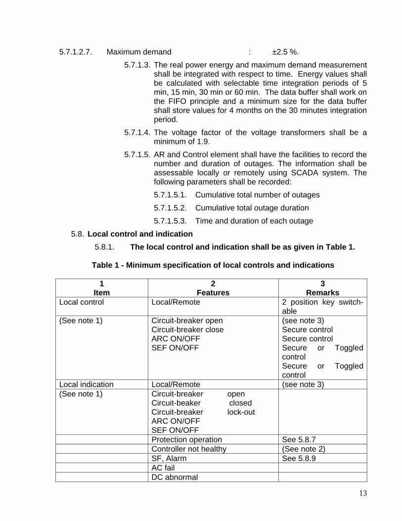
5.7.1.2.7. Maximum demand : ±2.5 %. 5.7.1.3. The real power energy and maximum demand measurement
shall be integrated with respect to time. Energy values shall be calculated with selectable time integration periods of 5 min, 15 min, 30 min or 60 min. The data buffer shall work on the FIFO principle and a minimum size for the data buffer shall store values for 4 months on the 30 minutes integration period.
5.7.1.4. The voltage factor of the voltage transformers shall be a minimum of 1.9.
5.7.1.5. AR and Control element shall have the facilities to record the number and duration of outages. The information shall be assessable locally or remotely using SCADA system. The following parameters shall be recorded: 5.7.1.5.1. Cumulative total number of outages 5.7.1.5.2. Cumulative total outage duration 5.7.1.5.3. Time and duration of each outage
5.8. Local control and indication 5.8.1. The local control and indication shall be as given in Table 1.
Table 1 - Minimum specification of local controls and indications
1
Item 2
Features 3
Remarks Local control Local/Remote 2 position key switch-
able (See note 1) Circuit-breaker open
Circuit-breaker close ARC ON/OFF SEF ON/OFF
(see note 3) Secure control Secure control Secure or Toggled control Secure or Toggled control
Local indication Local/Remote (see note 3) (See note 1) Circuit-breaker open
Circuit-beaker closed Circuit-breaker lock-out ARC ON/OFF SEF ON/OFF
Protection operation See 5.8.7 Controller not healthy (See note 2) SF, Alarm See 5.8.9 AC fail DC abnormal

14
DC fail Charger fail Local Analog indication (See note 1)
♦ r.m.s. phase-to-phase and phase to neutral voltage of all three phases
♦ r.m.s current per phase ♦ three-phase active power in kW
three-phase reactive power in kvars
♦ total three-phase active energy in kWh
♦ Power factor ♦ Maximum demand
NOTES (preferable)
Note 1: The local control and the local indication features on the control panel shall be labeled as presented in column 2, where applicable. The type of switch used for local control shall not allow for a conflict to exist between the switch position and the function status.
Note 2: The 'Controller not healthy' indication shall indicate the control equipment not
healthy (watchdog) function operated. It shall not operate during the normal pole-mounted switch operating cycle. This indication should remain active until the unhealthy state that initiated it returns to normal.
Note 3: The three-position switch (labeled as below) shall allow the AR controller to
be set in the following modes:
Remote: In this mode a local operator can trip the AR and change the mode. A remote operator can trip or close the AR and change configuration parameters. All reporting functions are active.
Local: In this mode a local operator can trip and close the AR and change
configuration parameters. Only monitoring functions are available to remote operators.
5.8.2. All local controls and indications shall be accessible in adverse
weather condition.
5.8.3. The AR shall be provided with external levers to permit manual operation, using an insulated operating stick, to open, close, lock-out and reset the AR from ground level. Where these operations can be performed at the control cabinet, it shall only be necessary to provide a mechanical means to open and lockout the circuit breaker using an insulated operating stick.

15
5.8.4. The AR status shall be clearly visible from ground level. "Opened" shall be indicated with a green "O". "Closed" shall be indicated by a red "I". Alternative indications shall be subject to approval by the purchaser.
5.8.5. Pressure relief facilities shall be provided to enable the AR to withstand safely the effects of excessive pressure rise due to an internal fault.
5.8.6. Malfunction of the AR shall not pose a safety hazard to the operator due to the recoil or backlash of items such as external operating rods, cranks and levers.
5.8.7. Easily available (i.e. maximum of one keystroke) local indication of protection operation shall be provided for at least the last operation of the AR. The function, phase involved and the current magnitude shall be indicated.
5.8.8. Switches used for local control shall offer the type of control described in table 1 i.e. secure or toggled control. Electronic keypad controls shall offer 'quick key' (maximum of one keystroke) access to the controls in table 1 if not implemented with switches.
5.8.9. ARs using SF, as an arc extinguishing medium shall: 5.8.9.1. Provide a low gas pressure indication at a gas pressure that
enables safe operation of the AR; 5.8.9.2. Prevent closing of the AR after it has opened under the
above-described condition; 5.8.9.3. Be provided with a method of inhibiting any operation of the
AR in the event of the gas pressure dropping below a safe pressure.
5.9. Remote control and indication 5.9.1. The remote controls and indications shall be as given in table 2.
Table 2 - Minimum specification of remote controls and indications
1 Item
2 Features
3 Remarks
Remote control Circuit-breaker open Circuit-breaker close ARC ON ARC OFF SEF ON SEF OFF
Secure control Secure control Secure control Secure control Secure control Secure control
Remote indication (See note 3)
Local/Remote Circuit-breaker open Circuit-breaker closed ARC lock-out
(see note 2)

16
ARC ON ARC OFF SEF ON SEF OFF IDMTL O/C Trip Low Set DTL O/C Trip Rapid O/C Trip High Set O/C Trip IDMTL E/F Trip Rapid E/F Trip High Set E/F Trip SEF Trip ARC Controller not healthy SF, Alarm A.C. fail D.C. abnormal D.C. fail Charger fail
(See note 4) (See note 1) See 5.8.9 5.13.5.3
Analog indication (See note 3)
♦ r.m.s. phase-to-phase and phase to neutral voltage of all three phases
♦ r.m.s current per phase ♦ three-phase active power in
kW ♦ three-phase reactive power in
kvars total three-phase active energy in kWh
♦ Power factor ♦ Maximum demand
Note 1 The 'Controller not healthy' indication shall indicate the control equipment not
healthy (watchdog) function operated. It shall not operate during the normal pole-mounted switch operating cycle. This indication should remain active until the unhealthy state that initiated it returns to normal.
Note 2 The two-position switch (labeled as below) shall allow the AR controller to be
set in the following modes:
Remote: In this mode a local operator can trip the AR and change the mode. A remote operator can trip or close the AR and change configuration parameters. All reporting functions are active.
Local: In this mode a local operator can trip and close the AR and change
configuration parameters. Only monitoring functions are available to remote operators. The local and remote Positions shall be indicated separately.

17
Note 4 The ARC indication shall give an alarm with any ARC attempt.
5.10. Local engineering 5.10.1. The AR controller shall contain a real time clock (with leap year
support) that can be set both locally and remotely. The requirements of Annex B shall be complied with. The accuracy of the clock shall be stated in the tender documentation.
5.10.2. A facility for selecting all the protection, operating and communications characteristics shall be locally available in the control cabinet. Optional password protection against unauthorized changes shall be available.
5.10.3. Non-volatile memory storage shall be sized to store the following minimum data: 5.10.3.1. All operating, protection and communications parameters. 5.10.3.2. An event record containing at least 3000 events (a
protection event is defined as all operations in a sequence until successful sequence reset or lockout). The actual number available shall be stated in the tender documentation.
5.10.3.3. Refer to 5.7.1.3. 5.10.3.4. Maximum demand information. Maximum demand shall
have the facilities to be configured for weekly or monthly demand.
5.10.4. A pointer shall be provided to indicate up to where the data was last read. This will enable regular uploading of the data without re-loading of previously read data.
5.10.5. All events shall be time and date stamped with a resolution of at least loms relative to the onboard real time clock.
5.11. Tele-control requirements 5.11.1. The AR controller shall detect and report disconnection of the control
cable between the controller and AR. 5.11.2. It shall be possible to operate AR, change the active protection
group, turn Auto-Recloser capabilities ON/OFF and turn E/F and SEF ON/OFF remotely using the protocol. This functionality shall be subject to the limitations of the selected protocol. Details shall be provided in the tender documentation.
5.12. Communications 5.12.1. The specifications are given at the end (communication for GPRS
and Server)

18
5.13. Power supplies 5.13.1. The AR system shall provide power for the electronics, operation of
the AR and operation of the communications equipment (e.g. radio or radio-modem).
5.13.2. Primary supply: Preference will be given to the ability to obtain primary power directly from the HV power system requiring no additional primary supply connection.
5.13.3. Test supply: The AR shall accept an external AC 230 V 50 Hz supply. 5.13.4. Optional supply: The AR shall accept an external DC 110 V supply. 5.13.5. Auxiliary supply: An auxiliary supply with the following minimum
characteristics shall be provided 5.13.5.1. One Maintenance Free Battery and constant voltage
charger with current limiting shall be part of the AR. Battery standby time shall not be less than 24 h, allowing for ten AR operations and a Transmit: Receive: Standby duty cycle of 5:5:90 from a 5 W output radio. The battery shall recharge to 80 % of its capacity in a maximum of 15 h. The total number of circuit-breaker operations under the above communications scenario shall be at least 10 AR operations preventing closing if the battery will not have enough stored energy to open the circuit- breaker for a protection trip condition. Details will be stated in the tender documentation.
5.13.5.2. Batteries shall be disconnected at the manufacturer's specified minimum voltage.
5.13.5.3. Battery Low' indication shall be available locally and remotely and shall include a battery test. The indication of "Battery Low" status shall allow for a further ten AR operations.
5.13.5.4. The minimum battery life expectancy shall be 5 years. Details of the guaranteed life expectancy of the battery shall be stated in the tender documentation.
5.14. Maintenance and commissioning All the communications equipment shall be easily accessible in the control cabinet. Wiring of "communications links in the control cabinet shall permit the connection of a temporary protocol-Monitor. It shall be possible to perform secondary injection testing while the AR is communicating with the center. 5.14.1. It shall be Possible to disconnect the AR circuit breaker and connect
a simulated breaker to the control cabinet for testing purposes. 5.14.2. The AR shall not malfunction while the radio is transmitting via an
antenna in close proximity and the control cabinet door is open.
19
5.14.3. Provision shall be made in the control cabinet for individually isolating the power supply to/from the following: 5.14.3.1. Battery; 5.14.3.2. Battery charger; 5.14.3.3. Radio; and 5.14.3.4. Primary supply to the control cabinet electronics.
5.15. Rating plate Each AR shall bear a rating plate of an intrinsically corrosion-resistant material, indelibly marked with the sea-level rating for which the equipment has been type tested. The rating plate shall be indelibly marked with: 5.15.1. The manufacturer's name; 5.15.2. The equipment type designation and serial number of the AR; 5.15.3. The mass, in kilograms; 5.15.4. The date of manufacture; 5.15.5. The voltage transformer ratio, class and burden. 5.15.6. Auxiliary supply voltage (if applicable); and
5.16. Additional information The following shall be submitted with the tender. 5.16.1. Circuit breaker details
5.16.1.1. manufacturer; 5.16.1.2. type designation; 5.16.1.3. place of manufacture; 5.16.1.4. short circuit breaking capacity; 3s 1s 5.16.1.5. asymmetrical breaking current; 5.16.1.6. peak making current; and 5.16.1.7. critical current (maximum instantaneous peak).
5.16.2. A schematic-wiring diagram of the AR offered. 5.16.3. A general-arrangement drawing of the AR offered. 5.16.4. Details of the maintenance and operating equipment and procedures
needed and a detailed parts list of the various components. 5.16.5. A description of the AR operation, with instruction and maintenance
manuals, including maintenance schedules, protection characteristics, communications facilities, the method of applying settings to relays and controls, together with any software required and the cost thereof. The software requirements shall be stated in the tender documentation.

20
5.16.6. Details and the cost of any available portable calibration and diagnostic test set that may be used to perform the functionality. Details of the test set shall be given in the tender document.
5.16.7. A list of recommended spares and tools, quoting the prices of each item and its availability.
5.16.8. If protection setting changes are accomplished by resistors, electronic cards or modules or computer programs, the price and range of such items. The method of changing protection settings shall be stated in the tender documentation.
5.16.9. Details of technical back-up facilities available. These details shall be stated in the tender documentation.
5.16.10. Details of the class, ratio(s) and burden of the protection current transformer and voltage transformer, if supplied, shall be stated in the tender documentation.
5.16.11. The supplier shall include the following details of measurement current transformers (not internal to the AR) that can be supplied with the AR. The following details shall be provided: 5.16.11.1. Available ratio(s) and accuracy class; 5.16.11.2. method of fitting; and 5.16.11.3. effect on creepage distance and BIL
5.16.12. Where applicable details of the low gas pressure alarm/lock-out philosophy;
5.16.13. Details of AR service history: 5.16.13.1. how many in service, where and for what period; and 5.16.13.2. contact names and numbers.
5.16.14. Details of LV trip/close coil if available as an option 5.16.15. Power requirements for a close operation 5.16.16. The maximum achievable separation between the control unit and
the circuit breaker. 5.16.17. Full details of the protocol implementation and the complete point
database.
6. TESTS 6.1. Type tests
6.1.1. The AR shall have been type tested in accordance with, and found to comply with, the requirements of either IEC 60056 or ANSI/IEEE C37.60-1981 for the following, and the appropriate. values shall be stated in the tender documentation: 6.1.1.1. Interrupting performance (automatic operation). 6.1.1.2. Interrupting performance (manual operation).
21
6.1.1.3. Operating duty. 6.1.1.4. Making current. 6.1.1.5. Minimum tripping current. 6.1.1.6. Insulation (dielectric tests). 6.1.1.7. Radio interference voltage. 6.1.1.8. Temperature rise. 6.1.1.9. Mechanical operations. 6.1.1.10. Control equipment surge withstand capability.
6.1.2. The control cabinet and associated electronics shall have been type tested in accordance with UNIPEDE NORM(SPEC)13 (1995): Automation and Control Apparatus for Generating Stations and Substations: Electromagnetic Compatibility Immunity Requirements. The environment shall be considered as failing in the HV substation category, according to NORM(SPEC)13.
6.1.3. Test records (on identical equipment) in the form of validated copies of test certificates issued by a recognized testing authority shall be submitted with the tender documentation.
6.2. Routine tests 6.2.1. Routine tests, as required in the relevant standards, shall be carried
out as a normal requirement of the contract and, unless otherwise agreed upon, shall be witnessed by the purchaser or by his appointed representative. No additional charge shall be levied for such tests or for the production or presentation of documentation related to routine tests.
6.2.2. Duplicate copies of routine test certificates shall be supplied together with the equipment when the latter is delivered to the final destination stated in the order.
7. PACKING/DOCUMENTATION 7.1. Packing
All equipment shall be carefully packed to prevent damage or deterioration during normal transportation, handling and storage. Each container shall bear the following information on the outside of the container: 7.1.1. The address of the destination 7.1.2. The gross mass, in kilograms 7.1.3. The name of the manufacturer 7.1.4. The purchaser's order number and port of destination

22
7.2. Documentation Each AR shall be supplied complete with the documentation specified in Items 5.16.1, 5.16.2. 5.16.3 and 5.16.4, together with the routine test certificates specified in 6.2.
8. 11 KV Las substation type - As per DHBVN Specs
9. a)11 KV NCTs Cast Resin (Outdoor Type) - As per DHBVN Specs b) 11 KV Transformer Diff Protection CTs – Class PS
GTP (CURRENT TRANSFORMER ) ELECTRICAL Ratio : 600-300/2.89 Freq : 50 Hz Acc. Cl : PS Burden : NA Size : To be given by bidder Knee point voltage 300 V, Max Magnetising current at Vk/4: 30mA RCT : NA ISF : NA ALF : NA
INSULATION Indoor / Outdoor : Outdoor Rated Sys. V : 11 kV Max Sys. V : 12 kV B.I. L. : 28 kV for 1 min / 75 kV peak Construction : Outdoor Polycrete type
INTER FACE Primary Type: Copper bar/pads Primary Size : To be given by bidder Sec. Type : Female inserts Sec. Size : To be given by bidder Mounting (IA) : To be given by bidder Polarity Marking : To be given by bidder Sec. Termi. Marking Label : To be given by bidder
TRACEBILITY / TESTS Typetest Ref (I.A) : Type Test Reports to be submitted

23
Routine tests to be Conducted with traceble Sr. No :
All routine tests to IS 2705 to be conducted and report to be submitted with the supply
ENVIRONMENT Working Ambient Temp. Range : 0 0C TO 80 0C Humidity : 98 % Rh at 20 C Max Temp rise at RF : To the requirements of IS 2705 c) 11 KV Metering CTs – Class 0.5
GTP (CURRENT TRANSFORMER ) ELECTRICAL Ratio : 600-300/5-5-5 Freq : 50 Hz Acc. Cl : 0.5 Burden : 15 VA Size : To be given by bidder Knee point voltage NA Magnetising current NA RCT : NA ISF : NA ALF : NA
INSULATION Indoor / Outdoor : Outdoor Rated Sys. V : 11 kV Max Sys. V : 12 kV B.I. L. : 28 kV for 1 min / 75 kV peak Construction : Outdoor Polycrete type
INTER FACE Primary Type: Copper bar/pads Primary Size : As in Drawing Sec. Type : Female inserts Sec. Size : To be given by bidder Mounting (IA) : To be given by bidder Polarity Marking : To be given by bidder Sec. Termi. Marking Label : To be given by bidder
TRACEBILITY / TESTS Typetest Ref (I.A) : Type Test Reports to be submitted

24
Routine tests to be Conducted with traceble Sr. No :
All routine tests to IS 2705 to be conducted and report to be submitted with the supply
ENVIRONMENT Working Ambient Temp. Range : 0 0C TO 80 0C Humidity : 98 % Rh at 20 C Max Temp rise at RF : To the requirements of IS 2705
10. 24 V DC Maintenance Free Battery with Charger (Required for only Transformer Differential Protection Relay Panel) –with RS 485 Modbus interface
11. LT Dist. Board - As per DHBVN Specs
12. 11/0.415 KV, 25 KVA Stn Transformer - As per DHBVN Specs
13. APFC Capacitors - As per DHBVN Specs
14. Steel Structures - Shall be suitable for the hardware provided and suitable structural drawings shall be provided. All the structures for the support of isolators, LAs, VCBs, CTs, PTs etc. Shall be made of Galvanised Steel or Aluminium Paint.
15. All overhead Bus shall be of Aluminium Tubular Busbar type with Flexible Termination at one end, in case of length of bus bar going beyond 3 m.
16. ACSR/AAAC conductors- As per DHBVN Specs For 11 KV overhead bus only Aluminium Tubular bus bars of Hindalco make to be used
17. C-Type Wedge connectors - As per DHBVN Specs
18. 11 KV Single core XLPE Cable, 630 mm2 - As per DHBVN Specs
19. 11 KV 3 core XLPE Cable, 185 mm2 - As per DHBVN Specs
20. 11 KV 3 core XLPE Cable, 25 mm2 - As per DHBVN Specs
21. LT 3.5 Core cable size 95 mm2 - As per DHBVN Specs
22. U/A Copper Cable 2C x 6 mm2 - As per DHBVN Specs
23. 2C x 4 mm2 - As per DHBVN Specs
24. 3C x 4 mm2 - As per DHBVN Specs
25. 7C x 2.5 mm2 - As per DHBVN Specs
26. 10C x 2.5 mm2 - As per DHBVN Specs
27. 4C x 4 mm2 - As per DHBVN Specs

25
28. 6C x 4 mm2 - As per DHBVN Specs
29. MS Channel 100x50x6 mm - As per DHBVN Specs
30. MS Angle 50x50x6 mm - As per DHBVN Specs
31. MS Flat 50x6 mm - As per DHBVN Specs
32. Earth Mat for Switchyard - As per DHBVN Specs
33. Foundation & Trenches for Yard etc. - As per DHBVN Specs
34. Switchyard Illumination System - As per DHBVN Specs
35. Fire Fighting Equipment - As per DHBVN Specs
36. Fire Fighting Equipment for yard - As per DHBVN Specs
37. Remote Monitoring System The entire sub station shall be linked to the remote control & Monitoring station
through a single communication tunnel using GPRS Routers. The s/s will be ready to
be hooked to the SCADA / EMS / DMS Software in future.
The DHBVN shall provide the Central control room at a remote control station with
an independent leased line (2 Mbps) for linking upto 30 such remote controlled s/s
on GPRS network.
The GPRS network shall provide a secured network utilizing standard (Dynamic IP)
GPRS enabled SIM cards of any service provider. The system should be
independent of the selection service provider, as DHBVN may chose any mix of
service providers for different substations (depending on the network quality in
respective regions) in other future jobs.
For the remote control, monitoring and adjustments Remote Monitoring and
Control/Configuration Software shall be provided to carryout following tasks as
minimum
o ON/OFF Operations
o Change the protection and control settings
o Up-Load the Event / Data and Demand Log
o Monitor Contact wear and Breaker health
o Monitor Battery and Battery Charger

26
o Communications settings
o Apply Work-Tags for maintenance
o Call-out configuration (In the event of pre-programmed alarm for call-out, the
device calls back the remote station to log the alarm)
o Send messages to the concerned field staff, in case of a call-out, by means of
SMS, Voice Call, E-Mail etc. (Depending on the local resources available, GSM
Service, LAN Administrator etc.)
GM/P&D CGM/P&D CGM/Commercial CGM/MM