EDS 06-0015 Pole-mounted Equipment Earthing...
31
Document Number: EDS 06-0015 Version: 4.1 Date: 09/12/2014 THIS IS AN UNCONTROLLED DOCUMENT, THE READER MUST CONFIRM ITS VALIDITY BEFORE USE ENGINEERING DESIGN STANDARD EDS 06-0015 POLE-MOUNTED EQUIPMENT EARTHING DESIGN Network(s): EPN, SPN Summary: This standard details the design requirements for the earthing of 33kV, 11kV and 6.6kV pole-mounted equipment. Author: Stephen Tucker Date: 09/12/2014 Approver: Steve Mockford Date: 21/01/2015 This document forms part of the Company’s Integrated Business System and its requirements are mandatory throughout UK Power Networks. Departure from these requirements may only be taken with the written approval of the Director of Asset Management. If you have any queries about this document please contact the author or owner of the current issue. Applicable To UK Power Networks External ☒ Asset Management ☒ G81 Website ☒ Capital Programme ☐ UK Power Networks Services ☒ Connections ☒ Contractors ☒ Health & Safety ☒ ICPs/IDNOs ☐ Legal ☐ Meter Operators ☒ Network Operations ☐ Procurement ☐ Strategy & Regulation ☐ Technical Training
Transcript of EDS 06-0015 Pole-mounted Equipment Earthing...

Document Number: EDS 06-0015
Version: 4.1
Date: 09/12/2014
TH
IS IS
AN
UN
CO
NT
RO
LL
ED
DO
CU
ME
NT
, T
HE
RE
AD
ER
MU
ST
CO
NF
IRM
IT
S V
AL
IDIT
Y B
EF
OR
E U
SE
ENGINEERING DESIGN STANDARD
EDS 06-0015
POLE-MOUNTED EQUIPMENT EARTHING DESIGN
Network(s): EPN, SPN
Summary: This standard details the design requirements for the earthing of 33kV, 11kV and 6.6kV pole-mounted equipment.
Author: Stephen Tucker Date: 09/12/2014
Approver: Steve Mockford Date: 21/01/2015
This document forms part of the Company’s Integrated Business System and its requirements are mandatory throughout UK Power Networks. Departure from these requirements may only be taken with the written approval of the Director of Asset Management. If you have any queries about this document please contact the author or owner of the current issue.
Applicable To
UK Power Networks External
☒ Asset Management ☒ G81 Website
☒ Capital Programme ☐ UK Power Networks Services
☒ Connections ☒ Contractors
☒ Health & Safety ☒ ICPs/IDNOs
☐ Legal ☐ Meter Operators
☒ Network Operations
☐ Procurement
☐ Strategy & Regulation
☐ Technical Training

Pole-mounted Equipment Earthing Design Document Number: EDS 06-0015
Version: 4.1
Date: 09/12/2014
© UK Power Networks 2015 All rights reserved 2 of 31
Revision Record
Version 4.1 Review Date 21/11/2019
Date 10/10/2017 Author Lee Strachan
Why has the document been updated – Minor version update
What has been updated – Reference to EDS 08-0030 changed to EDS 08-2109
Version 4.0 Review Date 21/11/2019
Date 09/12/2014 Author Stephen Tucker
Why has the document been updated – Periodic review
What has been updated - Updated to ensure consistency with the revised Overhead Line Manual. Changes include:
Earthing depth standardised at 1m (Section 5.4 and 7).
Preformed copper lattice earth mat introduced (Section 6.4).
Segregation on poles reduced to 120° and slow bend added to underground earthing on drawings (Section 7).
Additional LV PME earths added (Section 7.4).
Earth leakage solution added (Section 8.4).
Version 3.0 Review Date 19/01/2015
Date 13/10/2011 Author Stephen Tucker
Use of aluminium conductors added
Version 2.2 Review Date 19/01/2015
Date 26/09/2011 Author Stephen Tucker
Reclassification of document from Earthing Design Manual Section 5
Version 2.0 Review Date 19/01/2015
Date 16/03/2010 Author Stephen Tucker
Completely rewritten to provide a more consistent and practical approach and developed alongside the new Overhead Line Manual
Version 1.0 Review Date 31/03/2013
Date 31/03/2008 Author Stephen Tucker
Original

Pole-mounted Equipment Earthing Design Document Number: EDS 06-0015
Version: 4.1
Date: 09/12/2014
© UK Power Networks 2015 All rights reserved 3 of 31
Contents
1 Introduction ............................................................................................................. 5
2 Scope ....................................................................................................................... 5
3 Glossary and Abbreviations ................................................................................... 5
4 Definitions ................................................................................................................ 6
5 Design Criteria ......................................................................................................... 7
5.1 General Criteria ......................................................................................................... 7
5.2 Earth Potential Rise ................................................................................................... 8
5.3 Touch and Step Potentials ......................................................................................... 8
5.4 Electrode System ...................................................................................................... 9
5.5 Surge Arresters ....................................................................................................... 10
6 Earthing Requirements ......................................................................................... 11
6.1 Earth Resistance Values ......................................................................................... 11
6.2 Earth Electrodes ...................................................................................................... 11
6.3 Earthing and Bonding Conductors ........................................................................... 11
6.4 Earth Mat ................................................................................................................. 12
6.5 Auxiliary Supply Cables ........................................................................................... 12
7 Earthing Arrangements ......................................................................................... 13
7.1 General ................................................................................................................... 13
7.2 Steelwork ................................................................................................................ 13
7.2.1 HV Steelwork ........................................................................................................... 13
7.2.2 H-Poles ................................................................................................................... 13
7.2.3 LV Steelwork ........................................................................................................... 13
7.2.4 Anti-Climbing Device ............................................................................................... 13
7.3 Stays ....................................................................................................................... 14
7.4 LV PME Earths ........................................................................................................ 14
7.5 Pole-mounted Transformer ...................................................................................... 14
7.6 Cable Termination ................................................................................................... 17
7.7 Handle-Operated Air-Break Switch Disconnectors (ABSD) ...................................... 18
7.7.1 Handle-Operated ABSD .......................................................................................... 18
7.7.2 Handle-Operated ABSD and Cable Termination ...................................................... 18
7.8 Pole-Mounted Switches, Reclosers and Sectionalisers ........................................... 21
7.8.1 Low-Level Control Unit ............................................................................................ 21
7.8.2 High-Level Control Unit ........................................................................................... 21
7.9 Hook-Stick Operated Equipment ............................................................................. 24
7.9.1 General ................................................................................................................... 24
7.9.2 Hook-Stick Operated Equipment and Cable Termination ......................................... 25

Pole-mounted Equipment Earthing Design Document Number: EDS 06-0015
Version: 4.1
Date: 09/12/2014
© UK Power Networks 2015 All rights reserved 4 of 31
7.9.3 Hook-Stick Operated Equipment and Transformer .................................................. 27
8 Special Situations.................................................................................................. 28
8.1 HV and LV Combined Construction ......................................................................... 28
8.2 Third-Party Equipment on Shared HV or 33kV Poles ............................................... 28
8.3 Supplies to Mobile Phone Masts on National Grid Towers....................................... 28
8.4 Earth Leakage ......................................................................................................... 28
9 References ............................................................................................................. 30
Appendix A – Typical Electrode Systems ....................................................................... 31
Figures
Figure 6-1 – Buried Earth Mat ............................................................................................. 12
Figure 7-1 – Pole-mounted Transformer with HV Overhead Line and LV Overhead Line .... 15
Figure 7-2 – Pole-mounted Transformer with HV Overhead Line and LV Cable .................. 16
Figure 7-3 – Cable Termination with Surge Arresters .......................................................... 17
Figure 7-4 – Handle-Operated ABSD .................................................................................. 19
Figure 7-5 – Handle-Operated ABSD with Cable Termination ............................................. 20
Figure 7-6 – Pole-mounted Switchgear with Low-Level Control Unit ................................... 22
Figure 7-7 – Pole-mounted Switchgear with High-Level Control Unit .................................. 23
Figure 7-8 – Hook-Stick Operated ABSD ............................................................................ 24
Figure 7-9 – Hook-Stick Operated ABSD with Cable Termination ....................................... 25
Figure 7-10 – Hook-stick Operated Equipment with Cable Termination .............................. 26
Figure 7-11 – Hook-Stick Operated Equipment with a Pole-mounted Transformer .............. 27
Figure 8-1 – Metallic Strip Earth Leakage Device ................................................................ 29
Tables
Table 5-1 – Maximum EPR for a COLD Site Classification ................................................... 8
Table 6-1 – Earth Resistance Values .................................................................................. 11
Table 6-2 – Minimum Earth Electrodes (below ground) ....................................................... 11
Table 6-3 – Minimum Earthing and Bonding Conductors (above ground)............................ 11
Table 9-1 – 10Ω and 20Ω Earth Electrode Values ............................................................... 31

Pole-mounted Equipment Earthing Design Document Number: EDS 06-0015
Version: 4.1
Date: 09/12/2014
© UK Power Networks 2015 All rights reserved 5 of 31
1 Introduction
This standard (previously Section 5 of the Earthing Design Manual) details the design requirements for the earthing of 33kV, 11kV and 6.6kV pole-mounted equipment and includes standard arrangements for the installation of earthing and bonding. Note: 132kV equipment is beyond the scope of this standard.
The second issue of this standard aims to build on the original while providing a more consistent and practical approach. It has also been developed alongside the new Overhead Line Manual. It supersedes issue 1 and all previous EPN, SPN specific guidance on pole-mounted earthing.
Although this standard covers most aspects of pole-mounted earthing there will be some situations where advice from an earthing specialist is required, refer to EDS 06-0001 for further details.
The earthing design for secondary substations and LV networks (including LV overhead networks) are covered respectively in EDS 06-0014 and EDS 06-0016.
The construction of overhead networks including earthing is covered in further detail in the Overhead Line Manual.
This standard is divided into the following sub-sections:
Design criteria.
Earthing requirements.
Earthing arrangements.
Special situations.
Significant changes from existing practice or previous version:
Based on the guidance given in overhead line section of ENA TS 41-24 issued in 2009.
Comprehensive and practical earthing arrangements are now included for: pole-mounted transformers, cable terminations, handle-operated ABSDs, pole-mounted switchgear and hook-stick operated equipment.
2 Scope
This standard applies to the earthing for all new poles and any existing pole at voltages up to and including 33kV where refurbishment or a material alteration is to take place e.g. equipment replacement, installation or removal.
The earthing of towers and tower lines is outside of the scope of this standard and reference should be made to BS EN 50341.
This document is intended for internal and external use.
3 Glossary and Abbreviations
Term Definition
EPR Earth potential rise (refer to Section 4)
ROEP Rise of earth potential (refer to Section 4)
NetMap UK Power Networks graphical information system (GIS).

Pole-mounted Equipment Earthing Design Document Number: EDS 06-0015
Version: 4.1
Date: 09/12/2014
© UK Power Networks 2015 All rights reserved 6 of 31
4 Definitions
Earth Potential Rise (EPR) or Rise of Earth Potential (ROEP) EPR or ROEP is the potential (or voltage) rise that occurs on any steelwork due to the current that flows through the ground when an earth fault occurs on the HV or LV network.
Touch Potential The touch potential is the potential difference between a person’s hands and feet when standing up to 1m away from any earthed steelwork they are touching.
Step Potential The step potential is the potential difference between a person’s feet assumed to be 1m apart.
Transfer Potential The transfer potential is the potential transferred by means of a conductor between an area with a significant rise of earth potential and an area with little or no rise of earth potential, and results in a potential difference between the conductor and earth in both locations.
Substation Earthing Database The substation earthing database contains the classification (HOT or COLD) of all grid and primary substations together with the details of the EPR and other relevant earthing information. Refer to EDS 06-0004 for further details.
Cold Site A COLD site is a primary or secondary substation where the EPR is less than 430V, or 650V for sites with high reliability protection (refer to Table 5-1).
HOT Site A HOT site is a primary or secondary substation where the EPR is greater than 430V, or 650V for sites with high reliability protection (refer to Table 5-1). At a HOT secondary site the HV and LV earths must be segregated so that the potential on the HV earth during an earth fault is not transferred to the customer's LV earth terminal.
Combined Neutral and Earth (CNE) Typically used to describe a cable with a combined neutral and earth metallic outer sheath with a PVC covering, or overhead line with a combined neutral and earth conductor.
Combined Construction Combined construction is the installation of an HV and LV overhead line on the same pole. The LV overhead line is erected below the HV overhead line. Typically modern construction of this type of overhead line will consist of HV Covered Conductor and LV ABC although existing configurations of PVC covered HV and LV conductors are still in use.

Pole-mounted Equipment Earthing Design Document Number: EDS 06-0015
Version: 4.1
Date: 09/12/2014
© UK Power Networks 2015 All rights reserved 7 of 31
5 Design Criteria
5.1 General Criteria
Pole-mounted equipment is generally considered ‘out of reach’ if situated 4.3m or more above ground level. As such, touch potentials are not a consideration unless the steelwork extends below 4.3m or is connected to exposed metallic cable sheaths extending below this level. For new construction the equipment shall be a minimum of 5.1m (5.8m adjacent to roads) above ground or any object within 1.5m of the pole.
Therefore some poles may be left unearthed e.g. cross-arms and hook-stick operated equipment.
The following items of equipment shall always be earthed:
Transformers.
Switchgear with control units.
Switchgear with operating handles at low level.
Cable terminations.
Surge arresters.
Where any item of equipment on the pole is connected to earth all steelwork on the pole above 3.0m, including cross arms, pilot insulator pins, trussing gear, high voltage cable boxes etc., shall be connected to the main earth.
Steelwork below 3.0m, such as low level 33kV cable support steelwork, shall have a separate earth electrode installed and shall not be bonded to the main earth
On combined HV/LV construction the support steelwork and LV neutral/earth of the LV conductor system shall not be earthed or bonded to the main earth.
Pole-mounted earthing, where installed, shall be effective enough to provide the following function:
To pass the fault current during an earth fault back to the system neutral and therefore operate the source protection.
To limit the touch/step potential risk to staff operating switchgear to a safe value.
To prevent dangerous potentials appearing on the customers LV neutral/earth.
To discharge any lightning surges to earth.
The above requirements will be satisfied if the following design criteria are used for all new and refurbished pole earthing:
The maximum HV earth resistance value shall be 10Ω.
The maximum LV earth resistance value shall be 20Ω.
All above ground earth conductors shall be insulated for a minimum of 3m above ground level and mechanically protected (in accordance with the Overhead Line Manual) for a minimum of 2m above ground level.
The HV earth electrode shall be installed at the base of the pole except at locations where it is necessary for an operator to carry out switching operations. At these locations the HV earth electrode shall be installed on the opposite side of the pole to the operating position and 5m away from the operating position. Any earth conductor within 5m of the operating position shall be insulated except pole-mounted switchgear with low level control units (Figure 7-6).
The HV earth electrode system shall be installed at a minimum depth of 1m.
Pole-mounted Equipment Earthing Design Document Number: EDS 06-0015
Version: 4.1
Date: 09/12/2014
© UK Power Networks 2015 All rights reserved 8 of 31
The main earth conductor/electrode shall be insulated for a minimum of 1m below ground level.
Bare HV and LV earth electrodes buried in the ground shall be separated by a minimum of 8m.
Covered HV and LV earth conductors buried in the ground shall be separated by a minimum of 100mm.
HV and LV earthing systems on the same pole shall be segregated by 120°.
Earthing conductors associated with surge protection shall be kept as straight as possible with no sharp bends.
5.2 Earth Potential Rise
When an earth fault occurs on a cable or at a substation or pole, a proportion of the fault current will return to the source substation through the ground. This current will flow into the ground through the earth connection closest to the fault and will cause the voltage to rise above that of a remote (or true) earth. This voltage is known as earth potential rise (EPR) or rise of earth potential (ROEP) and is the earth fault current multiplied by the earth electrode resistance. Note: Some current will flow through the cable sheath back to the source and some will flow through the ground, it is only the current that flows through the ground that causes the EPR.
A site is classified as HOT when the EPR exceeds 430V, or 650V (for high reliability circuits) as defined in Table 5-1. However, at pole-mounted sites as there is no metallic earth return path, all of the current will flow through the ground. Therefore the EPR generally exceeds these values and the site is assumed to be HOT.
Table 5-1 – Maximum EPR for a COLD Site Classification
Substation Voltage Source Circuit Protection
EPR Comments
400kV, 275kV, 132kV, 66kV, 33kV, 25kV
High reliability 650V Main protection systems that clear the earth fault current within 200ms
Normal reliability 430V Main protection systems that clear the earth fault current in excess of 200ms
20kV, 11kV, 6.6kV Normal reliability 430V
5.3 Touch and Step Potentials
It is not always practicable to ensure that the step potentials directly above an installed earth electrode system remain below tolerable limits under earth fault conditions. It is generally considered that the probability of an earth fault occurring whilst an individual happens to be walking across the earth electrode at the same time, is extremely small. Additional protection is often afforded by the wearing of normal footwear which increases the foot-to-foot resistance. Therefore, in most circumstances no special precautions are required.
However, at sensitive locations that are often frequented by people, particularly barefoot children, and concentrations of livestock in stables or pens for example, precautions may be justified to eliminate or minimise the risk. This can usually be achieved by careful site selection or at the time of installation by installing the earth electrode in a direction away from the area of concern, burying the electrode as deep as practicable, and/or fencing the electrode off to prevent access.
Pole-mounted Equipment Earthing Design Document Number: EDS 06-0015
Version: 4.1
Date: 09/12/2014
© UK Power Networks 2015 All rights reserved 9 of 31
In high risk areas, such as horse riding schools or near milking parlours, special designs may be necessary and specialist advice should be sought.
The layout of earthing and bonding shall be so designed as to prevent dangerous potential gradients arising, from either step potentials on the ground, or touch potentials between adjacent parts of the installation. The former is achieved by having the external electrode at a suitable depth. The latter requirement is achieved by bonding.
However, at switchgear poles with low level handles or control units it is not possible to maintain the touch and step potentials to safe values for all foreseeable circumstances particularly during switching operations. Installing and maintaining an elaborate electrode system at a pole site, e.g. perimeter grading electrodes/rings, is not deemed to be practical and the integrity of this type of earthing system cannot always be assured.
Therefore as it is not possible to control the touch and step potentials at low level control boxes and handles the following control measures shall be adopted to mitigate the risk:
Dielectric boots and gloves shall be used for all switching operations at the poles with low level handles or control units.
Preferably, access to the equipment should be restricted e.g. by installing control units above 3m and installing hook-stick operated ABSDs.
5.4 Electrode System
A purpose designed electrode system will provide the necessary potential grading, minimise the step potential risk to humans and animals, cater for high frequency discharges from the surge arresters and provide sufficient separation between any operating platform and the high frequency electrode.
Any deviation from these arrangements, or failure to maintain the local earthing systems, can result in operators being placed at unacceptable risk.
The bare electrode system shall be:
Installed at a minimum depth of 1m.
Installed at a minimum distance of 5m and at least 120 away from any handle, cubicle or rod/hook-stick operating position.
Insulated within 5m of the operating position.
In addition to the above, the electrode system shall preferably be installed alongside hedges or other features. The following locations shall be avoided if possible:
Where persons could stand whilst operating any pole-top equipment.
Near metal fences, fence posts, buried cables, pipes.
Near camping or caravan parks where persons may be bare foot.
Across main farm gates.
Near drinking troughs or areas where livestock regularly congregate.
Across open fields where there is a risk of damage by ploughing or drainage works.
Examples of electrode systems for types of pole-mounted plant are shown in Section 7. Appendix A contains tables showing examples of the numbers and length of rods required to provide 10 ohm and 20 ohm electrode systems.
Pole-mounted Equipment Earthing Design Document Number: EDS 06-0015
Version: 4.1
Date: 09/12/2014
© UK Power Networks 2015 All rights reserved 10 of 31
5.5 Surge Arresters
The object of a surge arrester earthing is to:
Provide an easy, accessible and sufficient path to earth where the lightning current surge can be harmlessly dissipated.
Limit the voltage difference between the components of the protected equipment to prevent any insulation between them being stressed beyond its capabilities.
Therefore where surge arresters are installed:
The main earth conductor between the surge arrester and the electrode system shall be as short and straight as possible with no sharp bends.
Except at locations where it is necessary for an operator to carry out switching operations the electrode shall be installed at the base of the pole.
The main earth conductor shall be insulated to a depth of 1m below ground level (to reduce high step potentials).
At locations where it is necessary for an operator to carry out switching operations the earth electrode shall be installed 5m away from the base of pole to avoid unacceptable step potentials close to the operator. Any earth conductor within 5m of the operating position shall be insulated. The insulated conductor shall be installed inside a PVC duct to provide additional mechanical protection and insulation. It also serves to maintain the conductor in a slow bend which improves lightning performance.
The earth electrode resistance value shall not exceed 10Ω1.
1 It is generally accepted that 10Ω is the preferred maximum value and is in line with BS EN 62305-3 (Protection against lightning).

Pole-mounted Equipment Earthing Design Document Number: EDS 06-0015
Version: 4.1
Date: 09/12/2014
© UK Power Networks 2015 All rights reserved 11 of 31
6 Earthing Requirements
6.1 Earth Resistance Values
A summary of earth resistance values is given in Table 6-1. Electrode systems to achieve these values are given in Appendix A.
Table 6-1 – Earth Resistance Values
Electrode Resistance Value
HV Earth 10Ω2
Main LV Earth 20Ω
Additional LV PME Earth 100Ω
6.2 Earth Electrodes
The permitted earth electrodes are given in Table 6-2.
Table 6-2 – Minimum Earth Electrodes (below ground)
Function Network Fault Level Electrode3
Earth Electrode EPN Up to 4kA 35mm² bare stranded copper cable
SPN Up to 8kA 70mm² bare stranded copper cable
Earth rod Electrode EPN/SPN All 1m or 1.2m copper clad rods
6.3 Earthing and Bonding Conductors
The minimum size of earthing and bonding conductors are given in Table 6-3.
Table 6-3 – Minimum Earthing and Bonding Conductors (above ground)
Function Network Fault Level Earthing and Bonding Conductors3
Earth Conductor EPN Up to 4kA 50mm2 covered stranded aluminium cable
35mm2 covered stranded copper cable
SPN Up to 8kA 120mm2 covered stranded aluminium cable
70mm2 covered stranded copper cable
Bonding Conductor EPN/SPN All 35mm2 covered stranded aluminium cable
16mm2 covered stranded copper cable
2 The legacy earth resistance value for SPN 6.6kV networks was 6Ω however in practice this value wasn't widely adopted or obtainable therefore for consistency across the networks a maximum value of 10Ω has been selected. 3 Refer to EAS 06-0011 for a complete available range of earthing materials.
Pole-mounted Equipment Earthing Design Document Number: EDS 06-0015
Version: 4.1
Date: 09/12/2014
© UK Power Networks 2015 All rights reserved 12 of 31
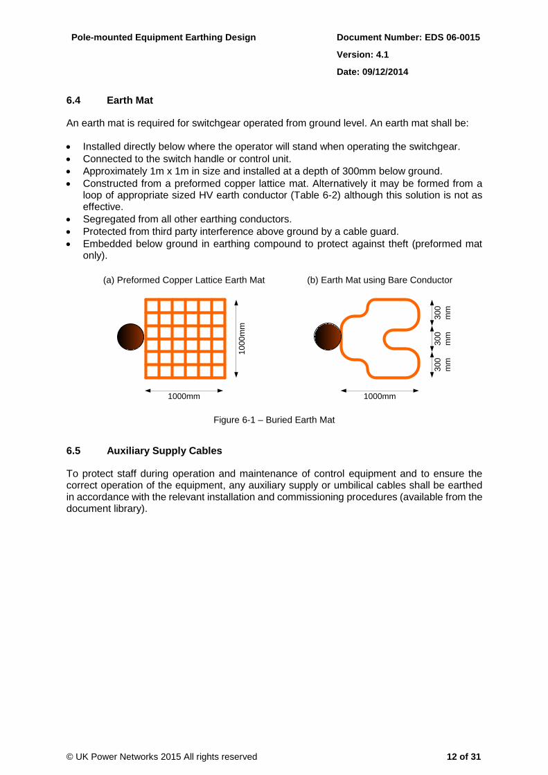
6.4 Earth Mat
An earth mat is required for switchgear operated from ground level. An earth mat shall be:
Installed directly below where the operator will stand when operating the switchgear.
Connected to the switch handle or control unit.
Approximately 1m x 1m in size and installed at a depth of 300mm below ground.
Constructed from a preformed copper lattice mat. Alternatively it may be formed from a loop of appropriate sized HV earth conductor (Table 6-2) although this solution is not as effective.
Segregated from all other earthing conductors.
Protected from third party interference above ground by a cable guard.
Embedded below ground in earthing compound to protect against theft (preformed mat only).
(a) Preformed Copper Lattice Earth Mat
1000mm
10
00
mm
1000mm
30
0
mm
30
0
mm
30
0
mm
(b) Earth Mat using Bare Conductor
Figure 6-1 – Buried Earth Mat
6.5 Auxiliary Supply Cables
To protect staff during operation and maintenance of control equipment and to ensure the correct operation of the equipment, any auxiliary supply or umbilical cables shall be earthed in accordance with the relevant installation and commissioning procedures (available from the document library).

Pole-mounted Equipment Earthing Design Document Number: EDS 06-0015
Version: 4.1
Date: 09/12/2014
© UK Power Networks 2015 All rights reserved 13 of 31
7 Earthing Arrangements
7.1 General
The standard earthing arrangements detailed in this section satisfy the design criteria and earthing requirements outlined in the previous sections and include:
HV and LV steelwork.
Stays.
Pole-mounted transformers with LV overhead line and LV cable.
Switches, reclosers and sectionalisers.
Handle-operated air-break switch disconnectors.
Hook-stick operated equipment.
Note: These arrangements demonstrate the earthing principles and should be constructed in accordance with the Overhead Line Manual. These arrangements can be applied to 33kV, 11kV and 6.6kV installations as required.
7.2 Steelwork
7.2.1 HV Steelwork
All HV pole-top steelwork supporting live equipment e.g. cross-arms, equipment supports etc., shall always be bonded together using the bonding conductor detailed in Table 6-3. However, the bonded steelwork shall only be earthed if it is necessary to earth other equipment on the pole.
7.2.2 H-Poles
Where H-poles are fitted with cross-bracing equipment, the lowest cross brace member shall be not less than 3m above the ground; where a cross-brace is found to be less than 3m above ground it shall be repositioned. Additionally:
On an earthed pole the cross-brace or tie-angle shall be bonded to the pole-top steelwork.
On an unearthed pole the cross-brace or tie-angle shall remain unbonded and unearthed.
On poles with low level cable support steelwork all steelwork less than 3m from the ground shall be independently earthed and shall not be bonded to the main HV earth.
7.2.3 LV Steelwork
LV pole-mounted equipment including voltage regulators, static balancers, metalclad fusegear, street lighting brackets, CNE cable sheaths, SNE cable sheaths and armours shall be bonded to the neutral earth conductor using the bonding conductor detailed in Table 6-3.
Reel insulator supports, pole bolts, D-irons and stay make-offs do not require bonding together.
7.2.4 Anti-Climbing Device
The anti-climbing device shall not be bonded to any other steelwork or connected to earth.

Pole-mounted Equipment Earthing Design Document Number: EDS 06-0015
Version: 4.1
Date: 09/12/2014
© UK Power Networks 2015 All rights reserved 14 of 31
7.3 Stays
All stays attached to a pole shall have a fully rated insulator or insulator(s) fitted in the stay in accordance with the Overhead Line Manual to prevent the bottom of the stay becoming live in the event of a pole-top insulation failure.
The pole-top make-off of all HV stays shall be bonded to the steelwork in accordance with the Overhead Line Manual.
The pole top make-offs of LV stays shall not be bonded to the steelwork.
7.4 LV PME Earths
On LV PME networks, additional earth electrodes are required at locations specified in EDS 06-0016. The additional PME earths shall be installed in accordance with the Overhead Line Manual.
7.5 Pole-mounted Transformer
The earthing system requirements for a pole-mounted transformer are outlined below and examples are shown Figure 7-1 and Figure 7-2.
The main HV earth conductor shall be connected from the pole-top steelwork to an HV underground earth electrode situated at the bottom of the pole. The HV earth shall be kept as straight as possible with no sharp bends.
The HV earth electrode shall be installed at minimum a depth of 1m.
The main earth conductor/electrode shall be insulated for a minimum of 1m below ground level.
The maximum value of the HV electrode shall be 10Ω.
All other steelwork shall be bonded to the main HV earthing.
An LV earth conductor shall be connected from the transformer neutral to an LV underground electrode system with a maximum value of 20Ω and segregated from the HV electrode system by at least 8m.
The HV and LV earth conductors shall be segregated by at least 120 on the pole.

Pole-mounted Equipment Earthing Design Document Number: EDS 06-0015
Version: 4.1
Date: 09/12/2014
© UK Power Networks 2015 All rights reserved 15 of 31
Ground Level
Min 8m Separation
1m
2.4
m m
in
All Steelwork
Connected to
HV Earth
HV Earth
Transformer
Earth
Terminal
Insulated for a
Minimum of 3m
Above Ground Level
Mechanical
Protection for a
Minimum of 2m
LV Earth Electrode
(to achieve max 20Ω)
HV Earth Electrode
(to achieve max 10Ω)
LV Earth
L1
L2
L3
N
N
L
Covered Aluminium
Earth Conductor
Bare Earth Conductor
Phase Conductor
Bare LV Overhead Line
Key:
Covered Copper Earth
Conductor
Bi-metallic Splice(150-300mm above ground)Bi-metallic Splice
(150-300mm above ground)
Neutral Conductor
Bi-metallic Splice(100mm below lowest crimp)
Note: Anti-climbing
Guards Not Shown
LV Network either
ABC or Open Wire
`
Figure 7-1 – Pole-mounted Transformer with HV Overhead Line and LV Overhead Line

Pole-mounted Equipment Earthing Design Document Number: EDS 06-0015
Version: 4.1
Date: 09/12/2014
© UK Power Networks 2015 All rights reserved 16 of 31
Ground Level
8m Separation
1m
2.4
m m
in
LV
Earth
LV CNE Cable
(PVC Covered)
Bond to LV CNE
Cable Shealth
All Steelwork
Connected to
HV Earth
HV
Earth
N
Transformer
Earth Terminal
L
LV Earth Electrode
(to achieve max 20Ω)HV Earth Electrode
(to achieve max 10Ω)
Covered Aluminium
Earth Conductor
Bare Earth Conductor
Phase Conductor
Key:
Covered Copper Earth
Conductor
Neutral Conductor
Bi-metallic Splice(150-300mm above ground)
Insulated for a
Minimum of 3m
Above Ground Level
Mechanical
Protection for a
Minimum of 2m
Bi-metallic Splice(100mm below lowest crimp)
Bi-metallic Splice(150-300mm above ground)
Note: Anti-climbing
Guards Not Shown
Figure 7-2 – Pole-mounted Transformer with HV Overhead Line and LV Cable
Note: Where a metallic sheathed hessian served LV cable is connected to a pole-mounted transformer the cable shall be replaced with a plastic sheathed cable for a minimum length of 8m to ensure HV/LV earth segregation is maintained.
Pole-mounted Equipment Earthing Design Document Number: EDS 06-0015
Version: 4.1
Date: 09/12/2014
© UK Power Networks 2015 All rights reserved 17 of 31
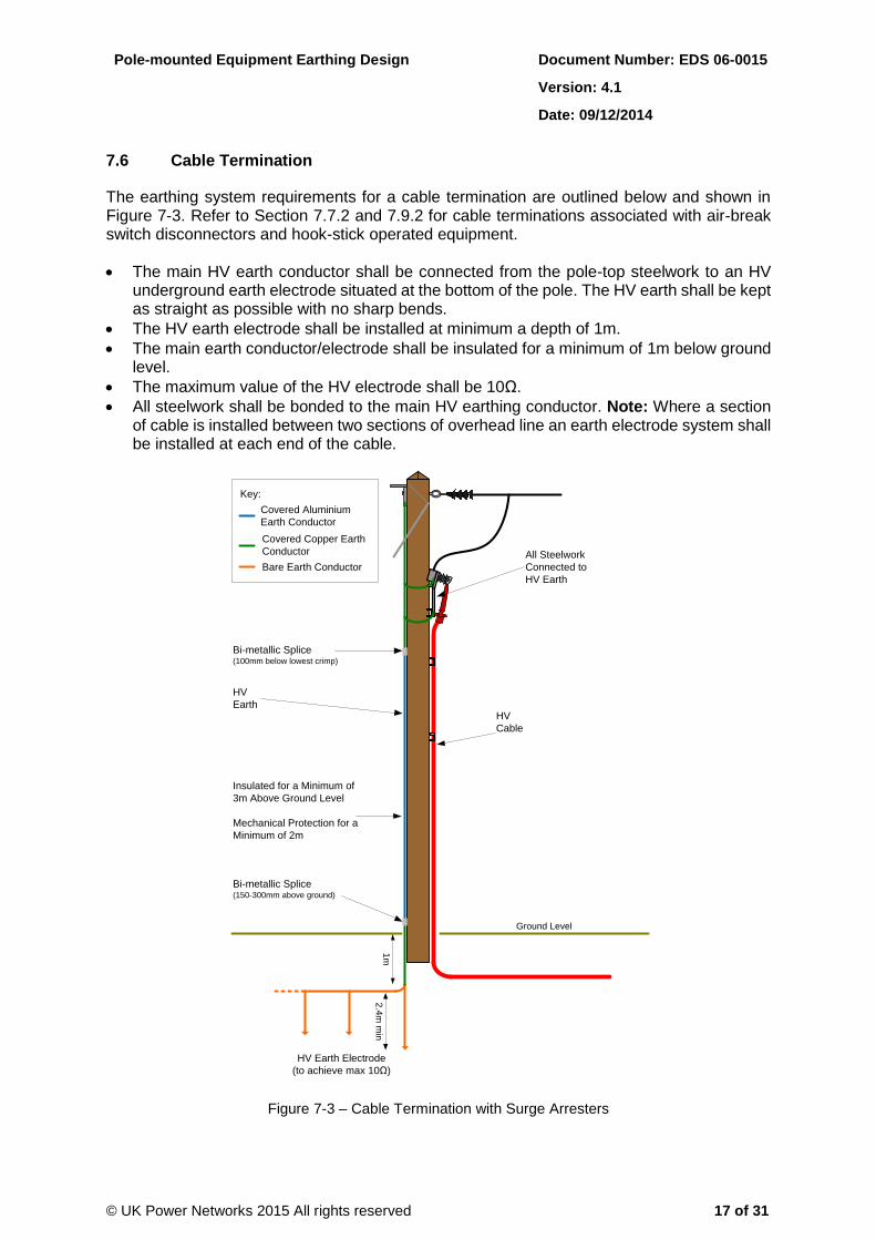
7.6 Cable Termination
The earthing system requirements for a cable termination are outlined below and shown in Figure 7-3. Refer to Section 7.7.2 and 7.9.2 for cable terminations associated with air-break switch disconnectors and hook-stick operated equipment.
The main HV earth conductor shall be connected from the pole-top steelwork to an HV underground earth electrode situated at the bottom of the pole. The HV earth shall be kept as straight as possible with no sharp bends.
The HV earth electrode shall be installed at minimum a depth of 1m.
The main earth conductor/electrode shall be insulated for a minimum of 1m below ground level.
The maximum value of the HV electrode shall be 10Ω.
All steelwork shall be bonded to the main HV earthing conductor. Note: Where a section of cable is installed between two sections of overhead line an earth electrode system shall be installed at each end of the cable.
Ground Level
All Steelwork
Connected to
HV Earth
HV
EarthHV
Cable
1m
2.4
m m
in
Insulated for a Minimum of
3m Above Ground Level
Mechanical Protection for a
Minimum of 2m
HV Earth Electrode
(to achieve max 10Ω)
Covered Aluminium
Earth Conductor
Bare Earth Conductor
Key:
Covered Copper Earth
Conductor
Bi-metallic Splice(150-300mm above ground)
Bi-metallic Splice(100mm below lowest crimp)
Figure 7-3 – Cable Termination with Surge Arresters

Pole-mounted Equipment Earthing Design Document Number: EDS 06-0015
Version: 4.1
Date: 09/12/2014
© UK Power Networks 2015 All rights reserved 18 of 31
7.7 Handle-Operated Air-Break Switch Disconnectors (ABSD)
7.7.1 Handle-Operated ABSD
The earthing system requirements for a handle-operated ABSD are outlined below and shown in Figure 7-4.
The main HV earth conductor shall be connected from the pole-top steelwork to an HV underground earth electrode situated 5m away from operating position and shall be kept as straight as possible with no sharp bends
The HV earth electrode shall be installed at minimum a depth of 1m .
The main earth conductor/electrode shall be insulated for a minimum of 5m below ground level and shall be installed in a duct between the pole and the first earth electrode.
The maximum value of the HV electrode shall be 10Ω.
The operating rod shall include a fully rated insulator.
All other steelwork, including the ABSD, above the operating rod insulator shall be bonded to the main HV earthing conductor.
An earth mat (refer to Section 6.4) shall be installed for the operator to stand on. The earth mat shall be connected to the switch handle but shall not be connected to the HV earth.
7.7.2 Handle-Operated ABSD and Cable Termination
The requirements of a handle-operated ABSD earthing system when installed on the same pole as a cable termination are outlined below and shown Figure 7-5. However, the preferred option is to install the ABSD on a separate pole where practical:
The main HV earth conductor shall be connected from the pole-top steelwork to an HV underground earth electrode situated 5m away from switch operating position and shall be kept as straight as possible with no sharp bends.
The HV earth electrode shall be installed at minimum a depth of 1m.
The main earth conductor/electrode shall be insulated for a minimum of 5m below ground level and shall be installed in a duct between the pole and the first earth electrode.
The maximum value of the HV electrode shall be 10Ω.
The operating rod shall include a fully rated insulator.
All steelwork above the operating rod insulator shall be bonded to the main HV earthing conductor.
An earth mat (refer to Section 6.4) shall be installed for the operator to stand on. The earth mat shall be connected to the switch handle but shall not be connected to the HV earth.
If a metallic sheathed hessian served cable is present either the equipment shall be moved to another pole or the cable in contact with the ground replaced with a modern PVC insulated equivalent for a minimum length of 5m.

Pole-mounted Equipment Earthing Design Document Number: EDS 06-0015
Version: 4.1
Date: 09/12/2014
© UK Power Networks 2015 All rights reserved 19 of 31
Plan View
Ground Level
5m Separation
1m
2.4
m m
in
All Steelwork
Connected to
HV Earth
HV
Earth
Insulated for a Minimum of
3m Above Ground Level
Mechanical Protection for a
Minimum of 2m
30
0
mm
Switch
Handle
Earth
Mat PVC Duct Installed from
Pole to Earth Rod
Operating Rod
Insulator
HV Earth Electrode
(to achieve max 10Ω)
Covered Aluminium
Earth Conductor
Bare Earth Conductor
Key:
Covered Copper Earth
Conductor
Bi-metallic Splice(150-300mm above ground)
Bi-metallic Splice(100mm below lowest crimp)
Figure 7-4 – Handle-Operated ABSD

Pole-mounted Equipment Earthing Design Document Number: EDS 06-0015
Version: 4.1
Date: 09/12/2014
© UK Power Networks 2015 All rights reserved 20 of 31
Ground Level
5m Separation
All Steelwork
Connected to
HV Earth
HV
Earth
Insulated for a Minimum of
3m Above Ground Level
Mechanical Protection for a
Minimum of 2m
30
0
mm
Switch
Handle
Operating Rod
Insulator
HV
Cable
Earth
Mat
PVC Duct Installed from
Pole to Earth Rod
Plan View
1m
2.4
m m
in
HV Earth Electrode
(to achieve max 10Ω)
Covered Aluminium
Earth Conductor
Bare Earth Conductor
Key:
Covered Copper Earth
Conductor
Bi-metallic Splice(150-300mm above ground)
Bi-metallic Splice(100mm below lowest crimp)
Figure 7-5 – Handle-Operated ABSD with Cable Termination

Pole-mounted Equipment Earthing Design Document Number: EDS 06-0015
Version: 4.1
Date: 09/12/2014
© UK Power Networks 2015 All rights reserved 21 of 31
7.8 Pole-Mounted Switches, Reclosers and Sectionalisers
7.8.1 Low-Level Control Unit
The earthing system requirements for pole-mounted switchgear with a low-level control unit are outlined below and shown in Figure 7-6.
The main HV earth conductor shall be connected from the pole-top steelwork to an HV underground earth electrode situated at the bottom of the pole and shall be kept as straight as possible with no sharp bends.
The HV earth electrode shall be installed at minimum a depth of 1m.
The main earth conductor/electrode shall be insulated for a minimum of 1m below ground level.
The maximum value of the HV electrode shall be 10Ω.
All other steelwork, including switchgear, surge arresters, voltage transformer, control unit etc, shall be connected to the main HV earthing.
The neutral of the auxiliary supply voltage transformer shall be connected to the HV earthing conductor.
An earth mat (refer to Section 6.4) shall be installed for the operator to stand on. The earth mat shall be connected to the control unit or main earth electrode.
Auxiliary supply and umbilical cables shall be earthed in accordance with the relevant installation procedure.
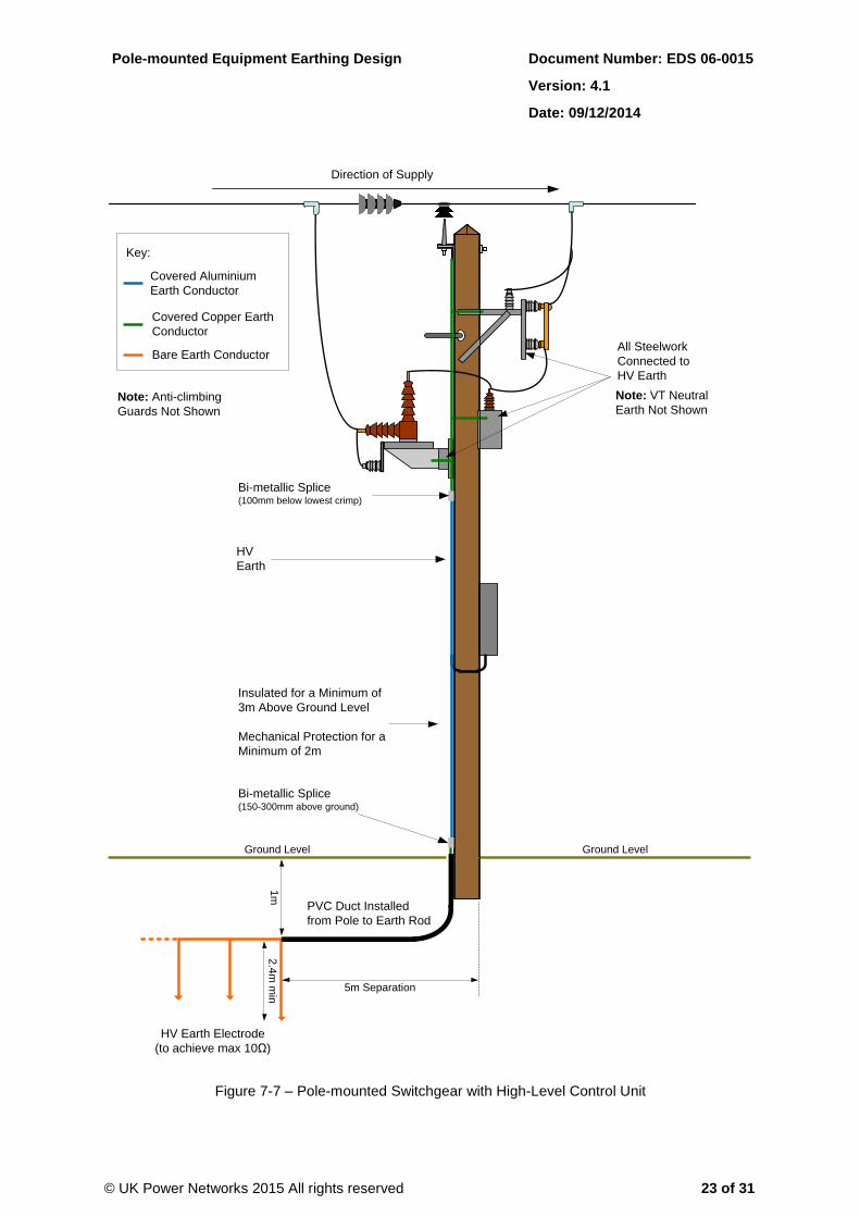
7.8.2 High-Level Control Unit
The earthing system requirements for pole-mounted switchgear with a high-level control unit are outlined below and shown in Figure 7-7.
The main HV earth conductor shall be connected from the pole-top steelwork to an HV underground earth electrode situated 5m away from switch operating position and shall be kept as straight as possible with no sharp bends.
The HV earth electrode shall be installed at minimum a depth of 1m.
The main earth conductor/electrode shall be insulated for a minimum of 5m below ground level and shall be installed in a duct between the pole and the first earth electrode.
The maximum value of the HV electrode shall be 10Ω.
All other steelwork, including switchgear, surge arresters, voltage transformer, control unit etc, shall be connected to the main HV earthing conductor.
The neutral of the auxiliary supply voltage transformer shall be connected to the HV earthing conductor.
Auxiliary supply and umbilical cables shall be earthed in accordance with the relevant installation procedure.

Pole-mounted Equipment Earthing Design Document Number: EDS 06-0015
Version: 4.1
Date: 09/12/2014
© UK Power Networks 2015 All rights reserved 22 of 31
Plan View
Ground Level
1m
2.4
m m
in
HV
Earth
30
0
mm
Earth Mat
HV Earth Electrode
(to achieve max 10Ω)
Bi-metallic Splice(100mm below lowest crimp)
Covered Aluminium
Earth Conductor
Bare Earth Conductor
Key:
Covered Copper Earth
Conductor
Direction of Supply
Insulated for a Minimum of
3m Above Ground Level
Mechanical Protection for a
Minimum of 2m
Bi-metallic Splice(150-300mm above ground)
Note: Anti-climbing
Guards Not Shown
All Steelwork
Connected to
HV Earth
Note: VT Neutral
Earth Not Shown
Figure 7-6 – Pole-mounted Switchgear with Low-Level Control Unit
Pole-mounted Equipment Earthing Design Document Number: EDS 06-0015
Version: 4.1
Date: 09/12/2014
© UK Power Networks 2015 All rights reserved 23 of 31
Ground Level
HV
Earth
Insulated for a Minimum of
3m Above Ground Level
Mechanical Protection for a
Minimum of 2m
Ground Level
5m Separation
PVC Duct Installed
from Pole to Earth Rod
1m
2.4
m m
in
All Steelwork
Connected to
HV Earth
Note: VT Neutral
Earth Not Shown
HV Earth Electrode
(to achieve max 10Ω)
Covered Aluminium
Earth Conductor
Bare Earth Conductor
Key:
Covered Copper Earth
Conductor
Bi-metallic Splice(150-300mm above ground)
Bi-metallic Splice(100mm below lowest crimp)
Note: Anti-climbing
Guards Not Shown
Direction of Supply
Figure 7-7 – Pole-mounted Switchgear with High-Level Control Unit

Pole-mounted Equipment Earthing Design Document Number: EDS 06-0015
Version: 4.1
Date: 09/12/2014
© UK Power Networks 2015 All rights reserved 24 of 31
7.9 Hook-Stick Operated Equipment
7.9.1 General
Rod or hook-stick operated equipment consists of ABSDs, fusegear, automatic sectionalising links (ASL) etc. When hook-stick operated equipment is installed on an unearthed pole an earthing system is not required however all of the steelwork shall be bonded together as shown in the ABSD example in Figure 7-8. Refer to Section 7.9.2 and 7.9.3 if the hook-stick operated equipment is installed on the same pole as other equipment.
Ground Level
All Steelwork
Bonded Together
Key:
Covered Copper Earth
Conductor
Figure 7-8 – Hook-Stick Operated ABSD

Pole-mounted Equipment Earthing Design Document Number: EDS 06-0015
Version: 4.1
Date: 09/12/2014
© UK Power Networks 2015 All rights reserved 25 of 31
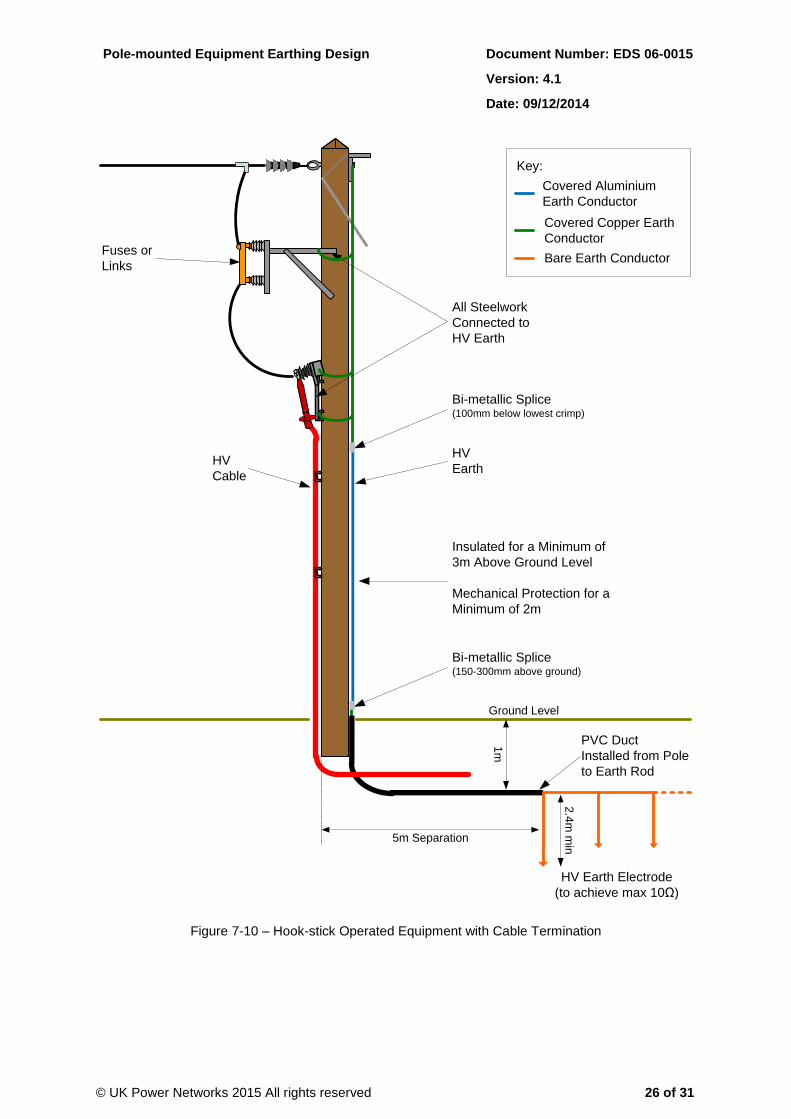
7.9.2 Hook-Stick Operated Equipment and Cable Termination
The earthing system requirements for hook-stick operated equipment installed on a pole with a cable termination are outlined below and shown in Figure 7-9 and Figure 7-10.
The main HV earth conductor shall be connected from the pole-top steelwork to an HV underground earth electrode situated 5m away from switch operating position and shall be kept as straight as possible with no sharp bends.
The HV earth electrode shall be installed at minimum a depth of 1m.
The main earth conductor/electrode shall be insulated for a minimum of 5m below ground level and shall be installed in a duct between the pole and the first earth electrode.
The maximum value of the HV electrode shall be 10Ω.
All other steelwork shall be bonded to the main HV earthing conductor.
If a metallic sheathed hessian served cable is present either the equipment shall be moved to another pole or the cable in contact with the ground replaced with a modern PVC insulated equivalent for a minimum length of 5m.
Ground Level
5m Separation
All Steelwork
Connected to HV
Earth
HV
Earth
1m
2.4
m m
in
HV Earth Electrode
(to achieve max 10Ω)
Covered Aluminium
Earth Conductor
Bare Earth Conductor
Key:
Covered Copper Earth
Conductor
Insulated for a Minimum
of 3m Above Ground
Level
Mechanical Protection
for a Minimum of 2m
HV
Cable
Bi-metallic Splice(150-300mm above ground)
Bi-metallic Splice(100mm below lowest crimp)
PVC Duct Installed from
Pole to Earth Rod
Figure 7-9 – Hook-Stick Operated ABSD with Cable Termination
Pole-mounted Equipment Earthing Design Document Number: EDS 06-0015
Version: 4.1
Date: 09/12/2014
© UK Power Networks 2015 All rights reserved 26 of 31
All Steelwork
Connected to
HV Earth
HV
Cable
HV
Earth
Ground Level
5m Separation
1m
2.4
m m
in
Fuses or
Links
HV Earth Electrode
(to achieve max 10Ω)
Covered Aluminium
Earth Conductor
Bare Earth Conductor
Key:
Covered Copper Earth
Conductor
Insulated for a Minimum of
3m Above Ground Level
Mechanical Protection for a
Minimum of 2m
Bi-metallic Splice(150-300mm above ground)
Bi-metallic Splice(100mm below lowest crimp)
PVC Duct
Installed from Pole
to Earth Rod
Figure 7-10 – Hook-stick Operated Equipment with Cable Termination

Pole-mounted Equipment Earthing Design Document Number: EDS 06-0015
Version: 4.1
Date: 09/12/2014
© UK Power Networks 2015 All rights reserved 27 of 31
7.9.3 Hook-Stick Operated Equipment and Transformer
The earthing system requirements for hook-stick operated equipment when installed on a pole with a transformer are outlined below and shown in Figure 7-11:
The main HV earth conductor shall be connected from the pole-top steelwork to an HV underground electrode situated 5m away from switch operating position and shall be kept as straight as possible with no sharp bends.
The HV earth electrode shall be installed at minimum a depth of 1m.
The main earth conductor/electrode shall be insulated for a minimum of 5m below ground level and shall be installed in a duct between the pole and the first earth electrode.
The maximum value of the HV electrode shall be 10Ω.
All other steelwork shall be bonded to the main HV earthing.
An LV earth conductor shall be connected from the transformer neutral to an LV underground electrode system with a maximum value of 20Ω and segregated from the HV electrode system by at least 8m.
The HV and LV earths shall be segregated on the pole by at least 120.
Ground Level
LV
Earth
Fuses
or LinksAll Steelwork
Connected to
HV Earth
NTransformer
Earth
Terminal
L
5m Separation
PVC Duct Installed from
Pole to Earth Rod
1m
2.4
m m
in
min 8m Separation LV Earth Electrode
(to achieve max 20Ω)HV Earth Electrode
(to achieve max 10Ω)
Covered Aluminium
Earth Conductor
Bare Earth Conductor
Phase Conductor
Key:
Covered Copper Earth
Conductor
Neutral Conductor
LV CNE Cable
(PVC Covered)
Bond to LV CNE
Cable Shealth
Bi-metallic Splice(150-300mm above ground)
Insulated for a Minimum of
3m Above Ground Level
Mechanical Protection for a
Minimum of 2m
Bi-metallic Splice(150-300mm above ground)
HV
Earth
Bi-metallic Splice(100mm below lowest crimp)
Note: Anti-climbing
Guards Not Shown
Figure 7-11 – Hook-Stick Operated Equipment with a Pole-mounted Transformer
Pole-mounted Equipment Earthing Design Document Number: EDS 06-0015
Version: 4.1
Date: 09/12/2014
© UK Power Networks 2015 All rights reserved 28 of 31
8 Special Situations
8.1 HV and LV Combined Construction
The earthing requirements for HV and LV combined construction poles are outlined below:
The HV steelwork and any HV stays shall be connected to an earth electrode at the base of the pole. The maximum value of the HV electrode shall be 10Ω.
The LV steelwork and any LV stays shall not be earthed or bonded to the HV steelwork.
Any HV and LV earth electrode below ground shall be separated by a minimum of 8m.
HV and LV earths on the same pole shall be segregated by at least 120°.
8.2 Third-Party Equipment on Shared HV or 33kV Poles
On existing 33kV or HV poles shared with third parties (e.g. BT) the steelwork and any stays shall be connected to an earth electrode at the base of the pole. The maximum value of the HV electrode shall be 10Ω. Alternatively an earth leakage device consisting of a metallic strip encircling the pole and connected to earth may be present (Figure 8-1).
Note: It is no longer permissible to install third party equipment on UK Power Networks 33kV or HV poles. Refer to the Overhead Line Manual for further information.
8.3 Supplies to Mobile Phone Masts on National Grid Towers
Special earthing requirements (not covered in this standard) are required for supplies to mobile phone masts on National Grid towers. Refer to EDS 08-2109 for further information.
8.4 Earth Leakage
Where leakage potentials are detected an earth leakage device consisting of a metallic strip encircling the pole and connected to earth (Figure 8-1) shall be installed in accordance with the overhead line manual.

Pole-mounted Equipment Earthing Design Document Number: EDS 06-0015
Version: 4.1
Date: 09/12/2014
© UK Power Networks 2015 All rights reserved 29 of 31
1.2
m
Insulated for a Minimum of
3m Above Ground Level
Mechanical Protection for
a Minimum of 2m
Covered Aluminium
Earth Conductor
Bare Earth Conductor
Key:
Covered Copper Earth
Conductor
Bi-metallic Splice(150-300mm above ground)
Ground Level
3m
Earth Leakage
Band
Danger of Death Sign
placed over Earth
Leakage Band after
Installation
Figure 8-1 – Metallic Strip Earth Leakage Device

Pole-mounted Equipment Earthing Design Document Number: EDS 06-0015
Version: 4.1
Date: 09/12/2014
© UK Power Networks 2015 All rights reserved 30 of 31
9 References
EDS 06-0001 Earthing Standard
EDS 06-0014 Secondary Substation Earthing Design
EDS 06-0016 LV Network Earthing Design
EDS 06-0018 NetMap Earthing Information System (internal document only)
EDS 08-2109 LV Supplies to Mobile Phone Base Stations Mounted on Transmission Towers
Overhead Line Manual
ENA TS 41-24 Section 15
Earthing associated with HV Distribution Overhead Line Networks (excluding Tower Lines and Pole Transformers)
BS EN 62305 Protection against Lightning
BS EN 50341 Overhead electrical lines exceeding AC 1kV – Part 1: General requirements – Common specifications

Pole-mounted Equipment Earthing Design Document Number: EDS 06-0015
Version: 4.1
Date: 09/12/2014
© UK Power Networks 2015 All rights reserved 31 of 31
Appendix A – Typical Electrode Systems
Table 9-1 shows various options for achieving HV and LV earth resistance values. Note: NetMap also contains earthing maps showing the earthing requirements to achieve 10Ω and 20Ω earths (refer to EDS 06-0018).
Actual earthing installation methods and arrangements are covered in the Overhead Line Manual and may help to achieve the desired value of earth resistance.
Table 9-1 – 10Ω and 20Ω Earth Electrode Values
Typical Soil Type/Resistivity
10Ω Earth Resistance 20Ω Earth Resistance
(a) (b) (a) (b)
Loam 25Ωm 1 x 2.4m 1 x 2.4m 1 x 1.2m 1 x 2.4m
Chalk 50Ωm 1 x 6.0m 2 x 2.4m 1 x 2.4m 1 x 2.4m
Clay 100Ωm 3 x 4.8m 4 x 2.4m 2 x 4.8m 2 x 2.4m
Sand, Gravel, Clay mix
<150Ωm 4 x 4.8m 7 x 2.4m 2 x 4.8m 3 x 2.4m
<200Ωm 5 x 4.8m 9 x 2.4m 3 x 4.8m 4 x 2.4m
>200Ωm Site specific design required
Slate, Shale, Rock
500Ωm Site specific design required
Column (a) denotes
Deep-driven Vertical and Horizontal Electrodes
Each deep-driven vertical electrode comprises of 1.2m rods coupled together to form the final vertical length e.g. 4.8m = 4 x 1.2m. Where there is more than one rod required, the spacing between them is 5m. The top of each electrode should be at a minimum depth of 0.6m below ground level
1.2
- 6
m
5m
Column (b) denotes
Short Vertical and Horizontal Electrodes
Each short-vertical electrode comprises of 1.2m rods coupled together to form the final vertical length e.g. 2.4m = 2 x 1.2m. Where there is more than 1 rod required, the spacing between them is 3m. The top of each electrode should be at a minimum depth of 0.6m below ground level
2.4
m
3m