SP12-23 6% Special Bulletin
16
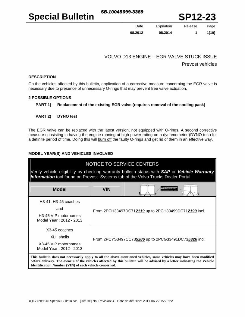
Special Bulletin SP12-23 <QF7720961> Special Bulletin SP - [Diffusé] No. Révision: 4 - Date de diffusion: 2011-06-22 15:28:22 Date Expiration Release Page 08.2012 08.2014 1 1(10) VOLVO D13 ENGINE – EGR VALVE STUCK ISSUE Prevost vehicles DESCRIPTION On the vehicles affected by this bulletin, application of a corrective measure concerning the EGR valve is necessary due to presence of unnecessary O-rings that may prevent free valve actuation. 2 POSSIBLE OPTIONS PART 1) Replacement of the existing EGR valve (requires removal of the cooling pack) PART 2) DYNO test The EGR valve can be replaced with the latest version, not equipped with O-rings. A second corrective measure consisting in having the engine running at high power rating on a dynamometer (DYNO test) for a definite period of time. Doing this will burn off the faulty O-rings and get rid of them in an effective way. MODEL YEAR(S) AND VEHICLES INVOLVED NOTICE TO SERVICE CENTERS Verify vehicle eligibility by checking warranty bulletin status with SAP or Vehicle Warranty Information tool found on Prevost–Systems tab of the Volvo Trucks Dealer Portal Model VIN H3-41, H3-45 coaches and H3-45 VIP motorhomes Model Year : 2012 - 2013 From 2PCH33497DC712119 up to 2PCH33499DC712199 incl. X3-45 coaches XLII shells X3-45 VIP motorhomes Model Year : 2012 - 2013 From 2PCYS3497CC735286 up to 2PCG33491DC735326 incl. This bulletin does not necessarily apply to all the above-mentioned vehicles, some vehicles may have been modified before delivery. The owners of the vehicles affected by this bulletin will be advised by a letter indicating the Vehicle Identification Number (VIN) of each vehicle concerned. SB-10045699-3389
Transcript of SP12-23 6% Special Bulletin
Special Bulletin SP12-23
<QF7720961> Special Bulletin SP - [Diffusé] No. Révision: 4 - Date de diffusion: 2011-06-22 15:28:22
Date Expiration Release Page
08.2012 08.2014 1 1(10)
VOLVO D13 ENGINE – EGR VALVE STUCK ISSUE
Prevost vehicles
DESCRIPTION
On the vehicles affected by this bulletin, application of a corrective measure concerning the EGR valve is necessary due to presence of unnecessary O-rings that may prevent free valve actuation. 2 POSSIBLE OPTIONS
PART 1) Replacement of the existing EGR valve (requires removal of the cooling pack)
PART 2) DYNO test The EGR valve can be replaced with the latest version, not equipped with O-rings. A second corrective measure consisting in having the engine running at high power rating on a dynamometer (DYNO test) for a definite period of time. Doing this will burn off the faulty O-rings and get rid of them in an effective way.
MODEL YEAR(S) AND VEHICLES INVOLVED
NOTICE TO SERVICE CENTERS
Verify vehicle eligibility by checking warranty bulletin status with SAP or Vehicle Warranty Information tool found on Prevost–Systems tab of the Volvo Trucks Dealer Portal
Model VIN
H3-41, H3-45 coaches
and
H3-45 VIP motorhomes Model Year : 2012 - 2013
From 2PCH33497DC712119 up to 2PCH33499DC712199 incl.
X3-45 coaches
XLII shells
X3-45 VIP motorhomes Model Year : 2012 - 2013
From 2PCYS3497CC735286 up to 2PCG33491DC735326 incl.
This bulletin does not necessarily apply to all the above-mentioned vehicles, some vehicles may have been modified before delivery. The owners of the vehicles affected by this bulletin will be advised by a letter indicating the Vehicle Identification Number (VIN) of each vehicle concerned.
SB-10045699-3389

Special Bulletin SP12-23
<QF7720961> Special Bulletin SP - [Diffusé] No. Révision: 4 - Date de diffusion: 2011-06-22 15:28:22
Date Expiration Release Page
08.2012 08.2014 1 2(10)
BEFORE UNDERTAKING ANY CORRECTIVE MEASURES, YOU MUST CHECK FIRST THAT THE PRESENT EGR VALVE IS REALLY INVOLVED. CHECK THE PART NUMBER AND DATE CODE ON THE EGR VALVE BODY (refer to the table of involved EGR valve below).
VOLVO PART NUMBER
DATE CODE OF AFFECTED EGR VALVE
1 21735861
from 086M to162M incl. 2 21735862
3 21735863
4 21735864

Special Bulletin SP12-23
<QF7720961> Special Bulletin SP - [Diffusé] No. Révision: 4 - Date de diffusion: 2011-06-22 15:28:22
Date Expiration Release Page
08.2012 08.2014 1 3(10)
PART 1 REPLACEMENT OF THE EGR VALVE
MATERIAL
Order the following parts:
Part No. Description Qty
21735863 EGR VALVE 1
20755169 V-BAND CLAMP, EGR HOT PIPE 2
20841816 GASKET, HOT PIPE 2
20850815 GASKET, EGR VALVE TWIN PORTS 1
976014 O-RING, OIL LINES 2
21528673 FLANGE SCREW, M10X90 4
NOTE
Material can be obtained through regular channels.
DANGER
Park vehicle safely, apply parking brake, stop engine. In the battery box, set the battery cut-off switch to the OFF position prior to working on the vehicle.
1) To easy removal and replacement of the EGR valve, you must proceed to the standard removal procedure of the cooling pack (charge air cooler, radiator, radiator fan clutch and angle drive assembly). Remove the cooling pack and proceed to the EGR valve replacement as described in EGR VALVE, REPLACEMENT procedure found on IMPACT (see images below).
RESULTS

Special Bulletin SP12-23
<QF7720961> Special Bulletin SP - [Diffusé] No. Révision: 4 - Date de diffusion: 2011-06-22 15:28:22
Date Expiration Release Page
08.2012 08.2014 1 4(10)
NOTE
TIGHTENING TORQUES
EGR VALVE MOUNTING FLANGE SCREW
Tighten the flange screws diagonally
Step 1. Tighten 15±3 lbf-ft (20±4 Nm)
Step 2. Tighten 45±4 lbf-ft (61±3 Nm)
EGR HOT PIPE V-BAND CLAMPS
Tighten to 50 lbf-in (6 Nm)

Special Bulletin SP12-23
<QF7720961> Special Bulletin SP - [Diffusé] No. Révision: 4 - Date de diffusion: 2011-06-22 15:28:22
Date Expiration Release Page
08.2012 08.2014 1 5(10)
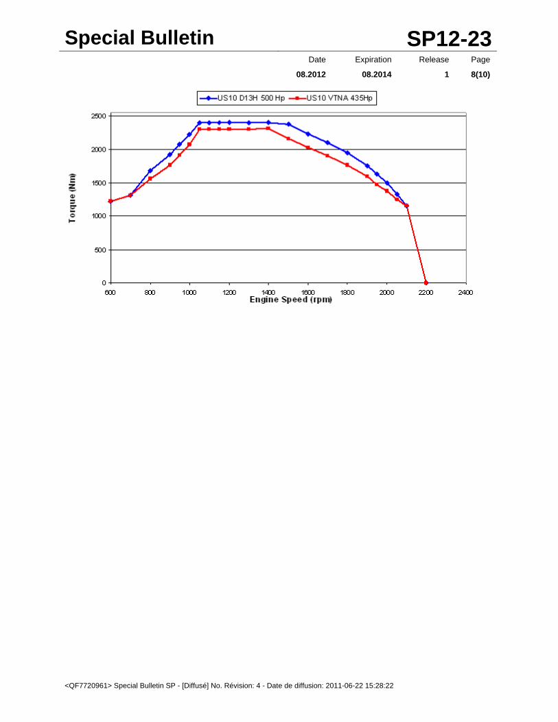
PART 2 DYNO TEST Here is the procedure to get rid (burn) of the EGR valve O-rings through a chassis DYNO test. GENERAL TEST GOAL We need T1 (EngExhTemp) to reach about 430°C (806°F) which should correspond to about 550°C (1022°F) exhaust manifold temperature. This 550C is our real target, but we have no temperature sensor there. We need to have that temperature for a minimum of 18 minutes.
T1 = Exhaust temperature at DPF Inlet = approximately exhaust temperature at engine outlet = EngExhTemp (in Volvo engineering tools). This is not DPF Temp!
T1 + 120°C (248°F) = approximately exhaust manifold temperature = approximately exhaust temperature at EGR valve (just for your information).
CHASSIS DYNO TECHNICAL REQUIREMENTS and PREPARATION
Select a heavy duty chassis DYNO that can handle HD Trucks wheel HP, high wheel torque (high HP at low RPM), and vehicle drive axle weight.
Minimum 300Hp at drive axle wheels. For more information please refer to technical details table at the end of this procedure.
VEHICLE PREPARATION
Check engine oil level. Closely monitor coolant level, and note it. We may need this information later on. Remove ABS fuse #23 (located in front electrical compartment).
Reason: rear wheels turning + front wheel not turning = Incoherence = ESP engaged. ABS fuse removal avoids this behavior.
IMPORTANT: to prevent activation of the AFSS (automatic fire suppression system), unplug connector L282A at the extinguisher cartridge.
HVAC running at full capacity if needed (see note 3 below). TEST PROCEDURE – Without Premium Tech Tool (BLIND TEST)
With Allison : Transmission should be set in 5th gear (see note 1 below). Adjust engine + DYNO parameters for engine to be running at FULL LOAD, at 1200 ~ 1250 RPM.
Make sure conditions are as stable as possible. Once a stable condition is reached, have a full load warm up of 2 minutes (see note 2 below). Run 18 minutes at full load ~1200 RPM (see note 2 below). Total = 20 minutes at FULL LOAD ~1200 RPM (see note 2 below).
Note 1: Transmission should be set in 5th gear. (At lower gears, high torque could break the DYNO.) Unfortunately fluctuations may occur, mainly at lower engine RPMs. At low RPM + high loads, the transmission has the tendency to down shift in 4th. If you use the DYNO of an Allison Transmission Dealer, the best thing would be to ask them to use the Allison DOC Interface tool, and perform a clutch test to really LOCK the transmission in 5th gear.
Special Bulletin SP12-23
<QF7720961> Special Bulletin SP - [Diffusé] No. Révision: 4 - Date de diffusion: 2011-06-22 15:28:22
Date Expiration Release Page
08.2012 08.2014 1 6(10)
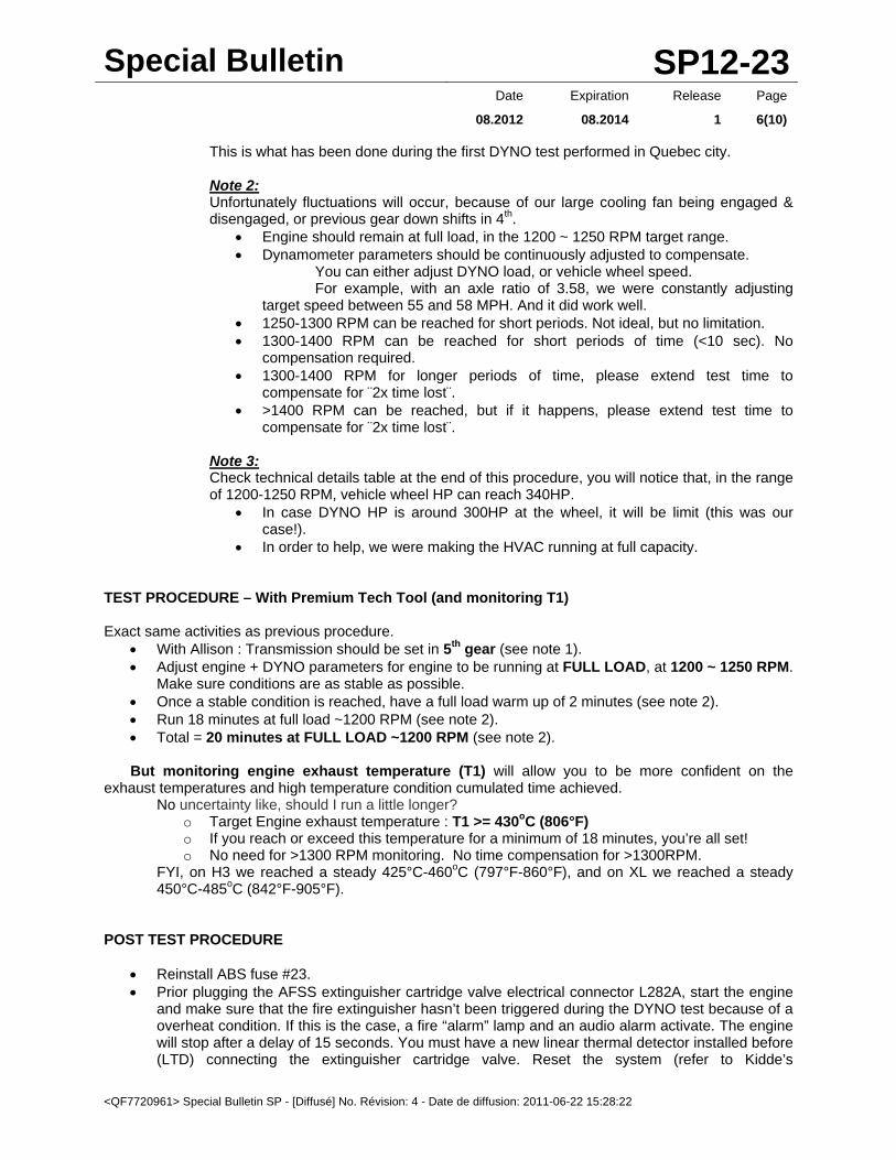
This is what has been done during the first DYNO test performed in Quebec city. Note 2: Unfortunately fluctuations will occur, because of our large cooling fan being engaged & disengaged, or previous gear down shifts in 4th.
Engine should remain at full load, in the 1200 ~ 1250 RPM target range. Dynamometer parameters should be continuously adjusted to compensate.
You can either adjust DYNO load, or vehicle wheel speed. For example, with an axle ratio of 3.58, we were constantly adjusting
target speed between 55 and 58 MPH. And it did work well. 1250-1300 RPM can be reached for short periods. Not ideal, but no limitation. 1300-1400 RPM can be reached for short periods of time (<10 sec). No
compensation required. 1300-1400 RPM for longer periods of time, please extend test time to
compensate for ¨2x time lost¨. >1400 RPM can be reached, but if it happens, please extend test time to
compensate for ¨2x time lost¨. Note 3: Check technical details table at the end of this procedure, you will notice that, in the range of 1200-1250 RPM, vehicle wheel HP can reach 340HP.
In case DYNO HP is around 300HP at the wheel, it will be limit (this was our case!).
In order to help, we were making the HVAC running at full capacity. TEST PROCEDURE – With Premium Tech Tool (and monitoring T1) Exact same activities as previous procedure.
With Allison : Transmission should be set in 5th gear (see note 1). Adjust engine + DYNO parameters for engine to be running at FULL LOAD, at 1200 ~ 1250 RPM.
Make sure conditions are as stable as possible. Once a stable condition is reached, have a full load warm up of 2 minutes (see note 2). Run 18 minutes at full load ~1200 RPM (see note 2). Total = 20 minutes at FULL LOAD ~1200 RPM (see note 2).
But monitoring engine exhaust temperature (T1) will allow you to be more confident on the
exhaust temperatures and high temperature condition cumulated time achieved. No uncertainty like, should I run a little longer?
o Target Engine exhaust temperature : T1 >= 430oC (806°F) o If you reach or exceed this temperature for a minimum of 18 minutes, you’re all set! o No need for >1300 RPM monitoring. No time compensation for >1300RPM.
FYI, on H3 we reached a steady 425°C-460oC (797°F-860°F), and on XL we reached a steady 450°C-485oC (842°F-905°F).
POST TEST PROCEDURE
Reinstall ABS fuse #23. Prior plugging the AFSS extinguisher cartridge valve electrical connector L282A, start the engine
and make sure that the fire extinguisher hasn’t been triggered during the DYNO test because of a overheat condition. If this is the case, a fire “alarm” lamp and an audio alarm activate. The engine will stop after a delay of 15 seconds. You must have a new linear thermal detector installed before (LTD) connecting the extinguisher cartridge valve. Reset the system (refer to Kidde’s

Special Bulletin SP12-23
<QF7720961> Special Bulletin SP - [Diffusé] No. Révision: 4 - Date de diffusion: 2011-06-22 15:28:22
Date Expiration Release Page
08.2012 08.2014 1 7(10)
OPERATION & MAINTENANCE MANUAL FOR FIRE PROTECTION SYSTEM AS INSTALLED ON PREVOST H345 & EPA10 VEHICLES)
Make sure dynamometer chains holding vehicle in place did not make scratches on paint. In case, please make touch-ups.
Verify plastic connectors and plastic hoses near urea injector to make sure it is not melted. Verify there is no coolant spill.
If you see a spill, please get back to us with few comments (quantity lost, coolant level change). And also tell us if this vehicle has a stainless steel surge tank (grey), or an aluminum tank (black paint).
TECHNICAL DETAILS TABLE RAR 3.91 - Target range in shaded area (approx. 1200 rpm, maximum torque, minimum rpm range)
RAR 3.58 - Target range in shaded area (approx. 1200 rpm, maximum torque, minimum rpm range)
Special Bulletin SP12-23
<QF7720961> Special Bulletin SP - [Diffusé] No. Révision: 4 - Date de diffusion: 2011-06-22 15:28:22
Date Expiration Release Page
08.2012 08.2014 1 8(10)
Special Bulletin SP12-23
<QF7720961> Special Bulletin SP - [Diffusé] No. Révision: 4 - Date de diffusion: 2011-06-22 15:28:22
Date Expiration Release Page
08.2012 08.2014 1 9(10)
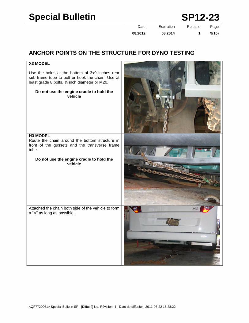
ANCHOR POINTS ON THE STRUCTURE FOR DYNO TESTING
X3 MODEL Use the holes at the bottom of 3x9 inches rear sub frame tube to bolt or hook the chain. Use at least grade 8 bolts, ¾ inch diameter or M20.
Do not use the engine cradle to hold the vehicle
H3 MODEL Route the chain around the bottom structure in front of the gussets and the transverse frame tube.
Do not use the engine cradle to hold the vehicle
Attached the chain both side of the vehicle to form a “V” as long as possible.

Special Bulletin SP12-23
<QF7720961> Special Bulletin SP - [Diffusé] No. Révision: 4 - Date de diffusion: 2011-06-22 15:28:22
Date Expiration Release Page
08.2012 08.2014 1 10(10)
PART 1 - ESTIMATED TIME
The time required to perform the replacement of the EGR valve is approximately:
- 4 hours.
- 8 hours when removal of the cooling pack is necessary. This modification is covered by Prevost’s normal warranty. We will reimburse you the parts and labor upon receipt of the replaced parts and a completed A.F.A. form on which you must specify as per "SP12-23".
Return replaced EGR valve to Prevost with A.F.A. for full reimbursement.
PART 2 - ESTIMATED TIME
This modification is covered by Prevost’s normal warranty. We will reimburse you four (4.0) hours of labor plus the dyno run cost upon receipt of a completed A.F.A. form on which you must specify as per "SP12-23".
OTHER
VBC Bulletin S8905
Fail Code 01-002
Defect Code 09
System Condition B
Causal Part 21299107
Prevost engages in a continuous program of testing and evaluating to provide the best possible product. Prevost, however, is not committed to, or liable for updating existing products.

<QF7720952> WB Prev - [Diffusé] No. Révision: 9 - Date de diffusion: 2011-06-22 15:17:24
WARRANTY BULLETIN
Wb12-28
DATE : AUGUST 2012 SECTION : 05 - Cooling
EXPIRATION: AUGUST 2014
SUBJECT : ALUMINUM COOLANT SURGE TANK RETROFIT
APPLICATION
Model VIN
X3-45 coaches Model Year : 2011 - 2013
From 2PCY33498BC735003 up to 2PCBS3496DC735299 incl.
This bulletin does not necessarily apply to all the above-mentioned vehicles, some vehicles may have been modified before delivery. The owners of the vehicles affected by this bulletin will be advised by a letter indicating the Vehicle Identification Number (VIN) of each vehicle concerned.
DESCRIPTION
On the vehicles affected by this bulletin, an improved coolant surge tank is available. This new surge tank offers a greater quantity of coolant between the low level sensor and the middle of sight glass level (5.2 quarts instead of 2.3 quarts). You will benefit from less frequent low coolant alarms.
MATERIAL
Order the following parts:
Part No. Description Qty
053597 DECAL 1
053641 COOLANT SURGE TANK, X3 SERIES ALUMINUM 1
053576 SUPPORT, COOLANT SURGE TANK (with clamp positioning tabs) 1
504775 T-BOLT CLAMP, DIA. 10-19" 2
NOTE
Material can be obtained through regular channels.

Wb12-28 Page 2 / 6
<QF7720952> WB Prev - [Diffusé] No. Révision: 9 - Date de diffusion: 2011-06-22 15:17:24
PROCEDURE
DANGER
Park vehicle safely, apply parking brake, stop engine and set battery master switch(es) to the OFF position prior to working on the vehicle.
REMOVAL OF THE ORIGINAL COOLANT SURGE COOLANT SURGE TANK
1. Cut the tie wrap holding the DEF lines to the coolant surge tank bracket.
2. Disconnect each hose connected to the coolant surge tank.
3. Place a clean rubber tube into the coolant surge tank. Using siphon effect, drain coolant surge tank.
4. Remove tie wraps and unplug low level sensor connector (5).
5. Loosen all fittings and sight glass.
6. Remove 3 bracket bolts (7) and remove coolant surge tank and bracket. Pull the coolant surge tank through the SCR converter.
7. Turn the tank in order to have the level sensor at the top, in a vertical position and then unscrew it from the coolant surge tank.
8. Remove sight glass and all fittings from coolant surge tank.
9. Loosen band clamps (10) and separate coolant surge tank from bracket. Return to Prevost for full reimbursement.
NEW COOLANT SURGE COOLANT SURGE TANK ARRANGEMENT

Wb12-28 Page 3 / 6
<QF7720952> WB Prev - [Diffusé] No. Révision: 9 - Date de diffusion: 2011-06-22 15:17:24
INSTALLATION OF NEW COOLANT SURGE COOLANT SURGE TANK
NOTE Use Loctite 567 Thread Sealant on all NPT threads (Prevost #680098).
NOTE
There is no specific tightening torques except when specified.
1. Using Loctite Thread Sealant 567 on threads, install level sensor in new coolant surge tank with sensor in a vertical position at the top of the tank. Tighten so that arrow on the side of the sensor is pointing up. Leave no more than two visible threads.
ARROW POINTING UP NO MORE THAN 2 VISIBLE THREADS
2. Install all hose fittings and sight glass using Loctite 567 Thread Sealant.
NYCTA Commuter only

Wb12-28 Page 4 / 6
<QF7720952> WB Prev - [Diffusé] No. Révision: 9 - Date de diffusion: 2011-06-22 15:17:24
or if applicable
3. Affix decal #053597 on surge tank. For NYCTA Commuter coaches, affix decal #053625 in addition.
4. Fix surge tank onto support. Tighten T-bolt clamps to 50 lbf-in.
5. Install coolant surge tank and support assembly in engine compartment. Tighten bolts to 16 lbf-ft.
6. Install all hoses and tighten properly.
7. Secure two DEF lines to tank support with tie wrap.
8. Use the cap from the original surge coolant surge tank on new surge tank.
9. Fill coolant surge tank to midpoint of sight glass and pressure test system. Close the heating system shut off valves to isolate this part of the system. Proceed to pressure test with 14 psi. Pressure should remain the same. Test for 5 to 10 minutes.
10. Run the coach and check coolant level once again.
Wb12-28 Page 5 / 6
<QF7720952> WB Prev - [Diffusé] No. Révision: 9 - Date de diffusion: 2011-06-22 15:17:24
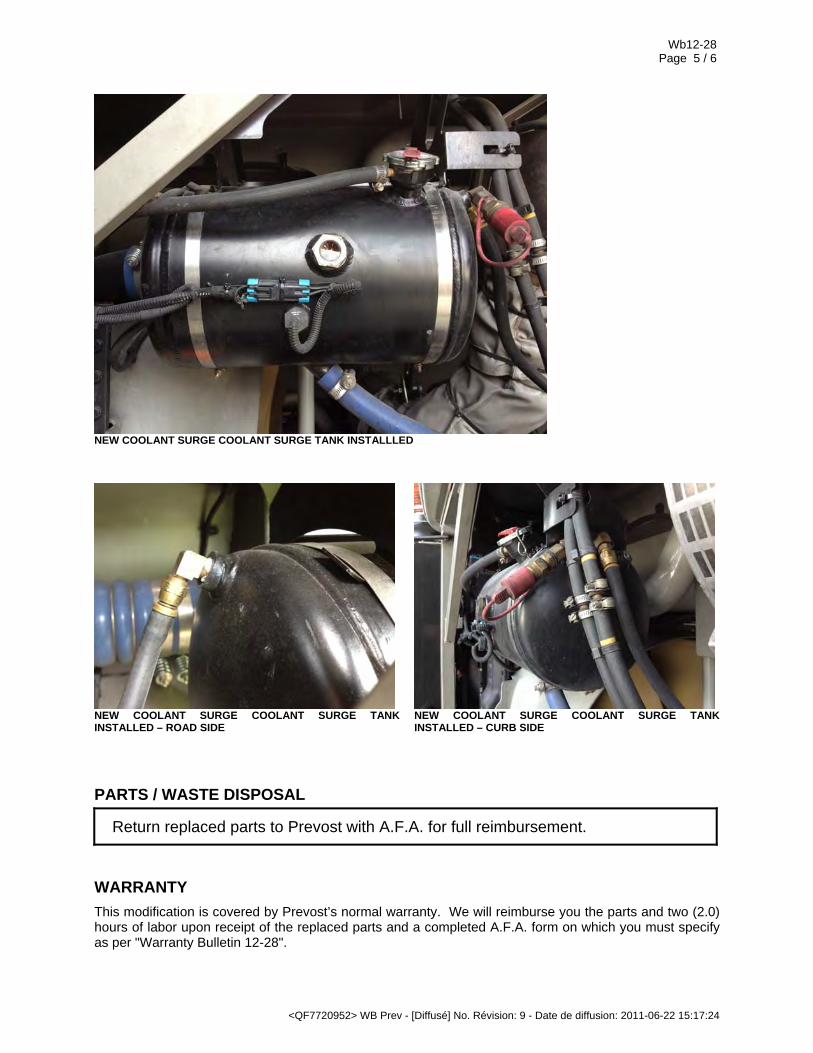
NEW COOLANT SURGE COOLANT SURGE TANK INSTALLLED
NEW COOLANT SURGE COOLANT SURGE TANK INSTALLED – ROAD SIDE
NEW COOLANT SURGE COOLANT SURGE TANK INSTALLED – CURB SIDE
PARTS / WASTE DISPOSAL
Return replaced parts to Prevost with A.F.A. for full reimbursement.
WARRANTY
This modification is covered by Prevost’s normal warranty. We will reimburse you the parts and two (2.0) hours of labor upon receipt of the replaced parts and a completed A.F.A. form on which you must specify as per "Warranty Bulletin 12-28".

Wb12-28 Page 6 / 6
<QF7720952> WB Prev - [Diffusé] No. Révision: 9 - Date de diffusion: 2011-06-22 15:17:24
OTHER VBC Bulletin n-a
Fail Code 05-07
Defect Code 09
System Condition B
Causal Part 053602