Special Bulletin SP12-01B Bulletin SP12-01B 01.2012 01.2014 4 1 ... VOLVO D13 ENGINE EPA2010 ... if...
25
Special Bulletin SP12-01B <QF7720961> Special Bulletin SP - [Diffusé] No. Révision: 4 - Date de diffusion: 2011-06-22 15:28:22 Date Expiration Release Page 01.2012 01.2014 4 1(25) Release 4: - Addition of air compressor mounting bolts torque, step 76 Release 3: - Addition of an alternate method for the repair: Pinning of the double idler gear VOLVO D13 ENGINE EPA2010 – DOUBLE IDLER GEAR REPAIR Prevost vehicles DESCRIPTION On certain EPA2010 vehicles equipped with VOLVO D13 engines, the pinning or the replacement of the double idler gear is necessary. US10 engines prior to serial number 964661 are involved. Before proceeding, verify vehicle eligibility by checking SP (Service Program) status in SAP or Vehicle Warranty Information tool on Prevost-System tab of the Volvo Trucks Dealer portal or use the Online Warranty System tool on Prevost web site www.prevostcar.com. Once on Prevost web site, select WARRANTY on SERVICE tab. Note: Check SAP or Vehicle Warranty Information tool for any open software bulletin and perform update before releasing the vehicle. 2 methods available to perform the repair Method 1 (shorter) - Pinning of the double idler gear This method is found on “SP215-017 DOUBLE IDLER GEAR PINNING MODIFICATION” available on Impact and on the Prevost Service Portal under Technical Publications. Method 2 (longer) - Replacement of the double idler gear This method is described in this bulletin. When this repair method has already been performed on a fleet, you may use this method to complete the remaining vehicles of the fleet. SB-10044284-8412
Transcript of Special Bulletin SP12-01B Bulletin SP12-01B 01.2012 01.2014 4 1 ... VOLVO D13 ENGINE EPA2010 ... if...

Special Bulletin SP12-01B
<QF7720961> Special Bulletin SP - [Diffusé] No. Révision: 4 - Date de diffusion: 2011-06-22 15:28:22
Date Expiration Release Page
01.2012 01.2014 4 1(25)
Release 4: - Addition of air compressor mounting bolts torque, step 76 Release 3: - Addition of an alternate method for the repair: Pinning of the double idler gear
VOLVO D13 ENGINE EPA2010 – DOUBLE IDLER GEAR REPAIR
Prevost vehicles
DESCRIPTION
On certain EPA2010 vehicles equipped with VOLVO D13 engines, the pinning or the replacement of the double idler gear is necessary. US10 engines prior to serial number 964661 are involved. Before proceeding, verify vehicle eligibility by checking SP (Service Program) status in SAP or Vehicle Warranty Information tool on Prevost-System tab of the Volvo Trucks Dealer portal or use the Online Warranty System tool on Prevost web site www.prevostcar.com. Once on Prevost web site, select WARRANTY on SERVICE tab. Note: Check SAP or Vehicle Warranty Information tool for any open software bulletin and perform update before releasing the vehicle.
2 methods available to perform the repair
Method 1 (shorter) - Pinning of the double idler gear
This method is found on “SP215-017 DOUBLE IDLER GEAR PINNING MODIFICATION” available on Impact and on the Prevost Service Portal under Technical Publications.
Method 2 (longer) - Replacement of the double idler gear
This method is described in this bulletin. When this repair method has already been performed on a fleet, you may use this method to complete the remaining vehicles of the fleet.
SB-10044284-8412
Special Bulletin SP12-01B
<QF7720961> Special Bulletin SP - [Diffusé] No. Révision: 4 - Date de diffusion: 2011-06-22 15:28:22
Date Expiration Release Page
01.2012 01.2014 4 2(25)
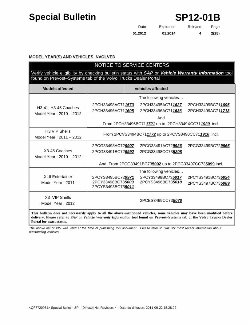
MODEL YEAR(S) AND VEHICLES INVOLVED
NOTICE TO SERVICE CENTERS
Verify vehicle eligibility by checking bulletin status with SAP or Vehicle Warranty Information tool found on Prevost–Systems tab of the Volvo Trucks Dealer Portal
Models affected vehicles affected
H3-41, H3-45 Coaches
Model Year : 2010 – 2012
The following vehicles…
2PCH33498AC711573
2PCH33496AC711605
2PCH33495AC711627
2PCH33496AC711636
2PCH33499BC711695
2PCH33499AC711713
And
From 2PCH33496BC711721 up to 2PCH3349XCC711920 incl.
H3 VIP Shells
Model Year : 2011 – 2012 From 2PCVS3494BC711772 up to 2PCVS3490CC711916 incl.
X3-45 Coaches
Model Year : 2010 – 2012
2PCG33498AC729907
2PCG33491BC729992
2PCG33491AC729926
2PCG33498CC735208
2PCG33499BC729965
And From 2PCG33491BC735002 up to 2PCG33497CC735099 incl.
XLII Entertainer
Model Year : 2011
The following vehicles…
2PCYS3495BC729971 2PCY33498BC735003 2PCYS3493BC735011
2PCY33498BC735017 2PCYS3496BC735018
2PCYS3491BC735024
2PCYS3497BC735089
X3 VIP Shells
Model Year : 2012 2PCBS3499CC735070
This bulletin does not necessarily apply to all the above-mentioned vehicles, some vehicles may have been modified before delivery. Please refer to SAP or Vehicle Warranty Information tool found on Prevost–Systems tab of the Volvo Trucks Dealer Portal for exact status.
The above list of VIN was valid at the time of publishing this document. Please refer to SAP for most recent information about outstanding vehicles
Special Bulletin SP12-01B
<QF7720961> Special Bulletin SP - [Diffusé] No. Révision: 4 - Date de diffusion: 2011-06-22 15:28:22
Date Expiration Release Page
01.2012 01.2014 4 3(25)
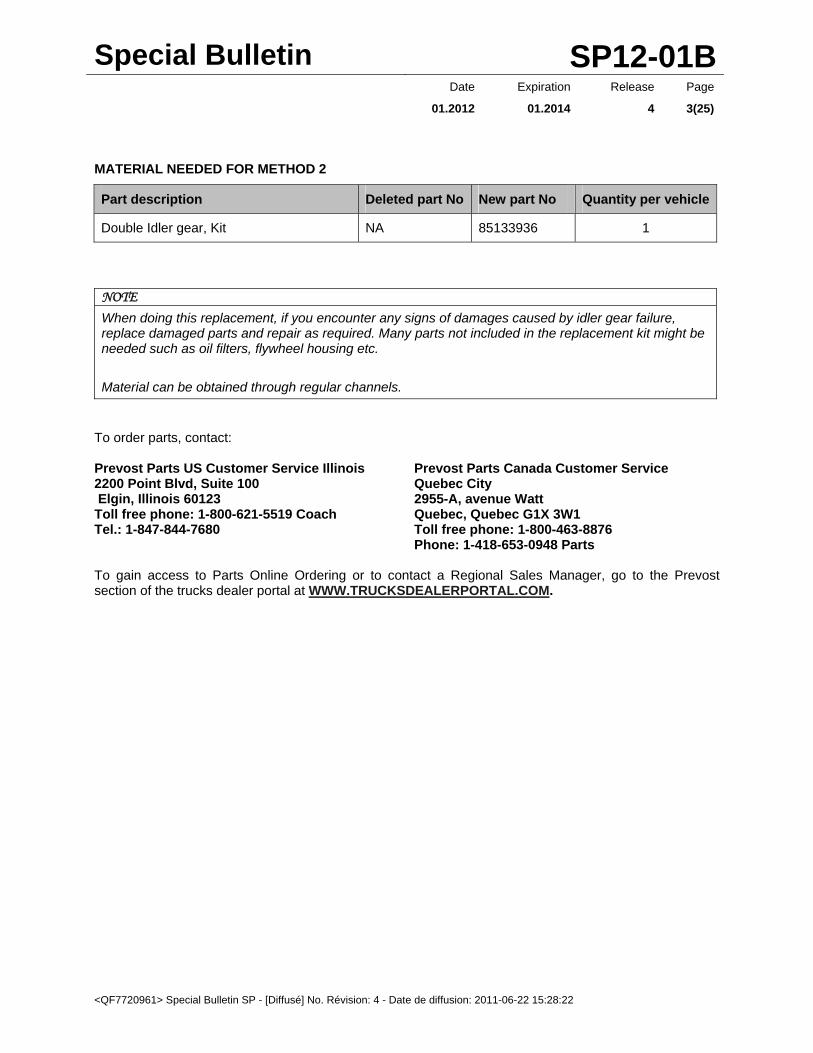
MATERIAL NEEDED FOR METHOD 2
Part description Deleted part No New part No Quantity per vehicle
Double Idler gear, Kit NA 85133936 1
NOTE
When doing this replacement, if you encounter any signs of damages caused by idler gear failure, replace damaged parts and repair as required. Many parts not included in the replacement kit might be needed such as oil filters, flywheel housing etc.
Material can be obtained through regular channels.
To order parts, contact: Prevost Parts US Customer Service Illinois 2200 Point Blvd, Suite 100 Elgin, Illinois 60123 Toll free phone: 1-800-621-5519 Coach Tel.: 1-847-844-7680
Prevost Parts Canada Customer Service Quebec City 2955-A, avenue Watt Quebec, Quebec G1X 3W1 Toll free phone: 1-800-463-8876 Phone: 1-418-653-0948 Parts
To gain access to Parts Online Ordering or to contact a Regional Sales Manager, go to the Prevost section of the trucks dealer portal at WWW.TRUCKSDEALERPORTAL.COM.

Special Bulletin SP12-01B
<QF7720961> Special Bulletin SP - [Diffusé] No. Révision: 4 - Date de diffusion: 2011-06-22 15:28:22
Date Expiration Release Page
01.2012 01.2014 4 4(25)
PROCEDURE – METHOD 2
DANGER
Park vehicle safely, apply parking brake, stop engine. In the battery box, set the battery cut-off switch to the OFF position prior to working on the vehicle.
You must read and understand the precautions and guidelines in Service Information, Impact, Function Group 20, "Engine Safety Practices" before performing this procedure. If you are not properly trained and certified in this procedure, ask your supervisor for training before you perform it.
DANGER
Before beginning any work on any part of the air system, be certain that the air pressure has been released. Failure to do so may cause a component to violently separate, which can result in serious personal injury.
DOUBLE IDLER GEAR KIT INCLUDES THE FOLLOWING PARTS
PART NO. DESCRIPTION / USE QTY
1543896 Crankshaft seal, rear 1
20817742 Gasket, timing gear cover 1
3092340 Sealant, tube 1
20850815 Gasket, EGR valve 1
21528673 flange screw M10X90, EGR valve mounting 4
20841816 Gasket, EGR hot pipe 2
992065 O-ring, air compressor 1
977030 O-ring, power steering pump 1
1547252 Gasket, rubber coolant pipe 1
20966752 O-ring, camshaft/crankshaft sensor 2
21007187 Gasket, diffuser pipe 1
967343 O-ring, EGR crossover pipe 2
21185086 Seal, timing cover 2
20493974 Seal, vent 1
20483919 Hexagonal socket screw, idler gear mounting 6
21826610 Idler gear 1
21095726 Seal, flexible pipe 1
21095721 Seal, flexible pipe 1
20555696 Seal, oil fill tube 1
Special Bulletin SP12-01B
<QF7720961> Special Bulletin SP - [Diffusé] No. Révision: 4 - Date de diffusion: 2011-06-22 15:28:22
Date Expiration Release Page
01.2012 01.2014 4 5(25)
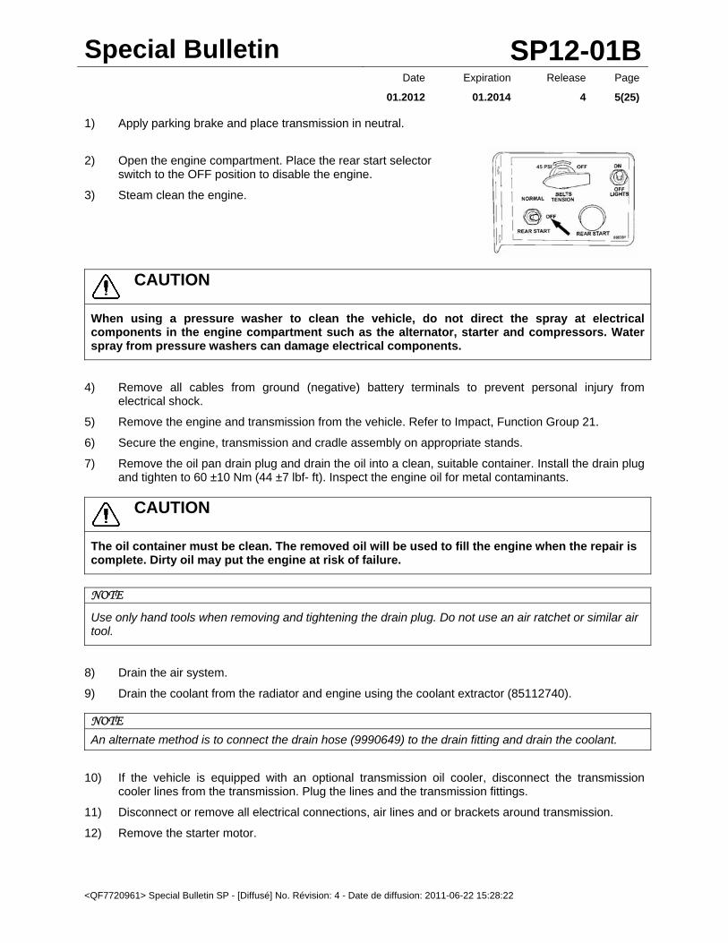
1) Apply parking brake and place transmission in neutral.
2) Open the engine compartment. Place the rear start selector switch to the OFF position to disable the engine.
3) Steam clean the engine.
CAUTION
When using a pressure washer to clean the vehicle, do not direct the spray at electrical components in the engine compartment such as the alternator, starter and compressors. Water spray from pressure washers can damage electrical components.
4) Remove all cables from ground (negative) battery terminals to prevent personal injury from electrical shock.
5) Remove the engine and transmission from the vehicle. Refer to Impact, Function Group 21.
6) Secure the engine, transmission and cradle assembly on appropriate stands.
7) Remove the oil pan drain plug and drain the oil into a clean, suitable container. Install the drain plug and tighten to 60 ±10 Nm (44 ±7 lbf- ft). Inspect the engine oil for metal contaminants.
CAUTION
The oil container must be clean. The removed oil will be used to fill the engine when the repair is complete. Dirty oil may put the engine at risk of failure.
NOTE
Use only hand tools when removing and tightening the drain plug. Do not use an air ratchet or similar air tool.
8) Drain the air system.
9) Drain the coolant from the radiator and engine using the coolant extractor (85112740).
NOTE
An alternate method is to connect the drain hose (9990649) to the drain fitting and drain the coolant.
10) If the vehicle is equipped with an optional transmission oil cooler, disconnect the transmission cooler lines from the transmission. Plug the lines and the transmission fittings.
11) Disconnect or remove all electrical connections, air lines and or brackets around transmission.
12) Remove the starter motor.

Special Bulletin SP12-01B
<QF7720961> Special Bulletin SP - [Diffusé] No. Révision: 4 - Date de diffusion: 2011-06-22 15:28:22
Date Expiration Release Page
01.2012 01.2014 4 6(25)
NOTE
Label the wiring to the starter relay.
13) Place transmission jack under transmission and remove transmission. Refer to Impact, Function Group 43.
14) Remove clutch and pressure plate from flywheel with removal jack. Refer to Impact, Function Group 41.
15) Remove the valve cover fasteners. Remove the valve cover. Refer to Impact, Function Group 21.
16) Install the flywheel turning tool (88800014). Rotate the flywheel (crankshaft) until the camshaft is positioned at top dead center (TDC) and zero mark on flywheel.
17) Remove the crankshaft sensor.
NOTE
Label the connectors to the camshaft sensor and crankshaft sensor for correct installation.
18) Remove the flywheel. Refer to Impact, Function Group 21.
19) If equipped, remove the fastener and P-clamp securing the line to the mounting bracket on the diffuser pipe. Disconnect fuel line from aftertreatment injector. Collect any residual fuel that might be in the line in a suitable container.

Special Bulletin SP12-01B
<QF7720961> Special Bulletin SP - [Diffusé] No. Révision: 4 - Date de diffusion: 2011-06-22 15:28:22
Date Expiration Release Page
01.2012 01.2014 4 7(25)
DANGER
Fuel leaked or spilled onto hot surfaces or electrical components can cause a fire and result in component damage and serious personal injury.
CAUTION
Do not kink the fuel and coolant lines. Kinking the lines may result in leakage.
20) If equipped, remove air line and coolant lines from aftertreatment injector.
1. Air Line 2. Fuel Line 3. Coolant Line
21) Loosen clamp between diffuser and turbocharger. Remove diffuser.
22) Remove EGR hot pipe heat shield and the EGR hot pipe.
23) Remove the EGR valve. Refer to Impact, Function Group 29.

Special Bulletin SP12-01B
<QF7720961> Special Bulletin SP - [Diffusé] No. Révision: 4 - Date de diffusion: 2011-06-22 15:28:22
Date Expiration Release Page
01.2012 01.2014 4 8(25)
24) Remove the camshaft position sensor and shims. Discard O-ring.
NOTE
Label the connectors to the camshaft sensor and crankshaft sensor for correct installation.
25) Remove all straps, P-clamps and other retainers used to restrain harness, lines and tubes to the rear of the engine.
26) Remove air compressor. Discard sealing ring. For further details, refer to “Compressor, Replacement” found in Impact under function group 561.
27) Remove the timing gear cover. Discard gaskets.
28) Remove power steering pump/fuel pump fasteners and secure out of the way. Disconnect fuel lines from pump. Collect any residual fuel that might be in the line in a suitable container. Do not remove steering fluid lines. Discard sealing ring.
29) If the vehicle is equipped with a transmission oil cooler, it may be necessary to remove pipe and hose mounting brackets.
NOTE
Mark the transmission oil cooler bracket stud locations to aid in reassembly.
Special Bulletin SP12-01B
<QF7720961> Special Bulletin SP - [Diffusé] No. Révision: 4 - Date de diffusion: 2011-06-22 15:28:22
Date Expiration Release Page
01.2012 01.2014 4 9(25)
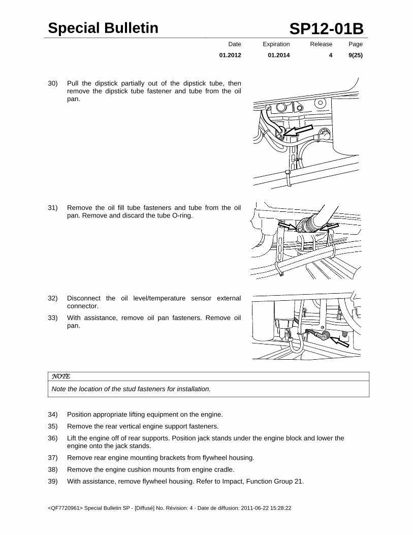
30) Pull the dipstick partially out of the dipstick tube, then remove the dipstick tube fastener and tube from the oil pan.
31) Remove the oil fill tube fasteners and tube from the oil pan. Remove and discard the tube O-ring.
32) Disconnect the oil level/temperature sensor external connector.
33) With assistance, remove oil pan fasteners. Remove oil pan.
NOTE
Note the location of the stud fasteners for installation.
34) Position appropriate lifting equipment on the engine.
35) Remove the rear vertical engine support fasteners.
36) Lift the engine off of rear supports. Position jack stands under the engine block and lower the engine onto the jack stands.
37) Remove rear engine mounting brackets from flywheel housing.
38) Remove the engine cushion mounts from engine cradle.
39) With assistance, remove flywheel housing. Refer to Impact, Function Group 21.

Special Bulletin SP12-01B
<QF7720961> Special Bulletin SP - [Diffusé] No. Révision: 4 - Date de diffusion: 2011-06-22 15:28:22
Date Expiration Release Page
01.2012 01.2014 4 10(25)
40) Remove double idler gear (item 2). Discard fasteners.
1. Crankshaft Gear
2. Double Idler Gear
3. Idler Gear, Adjustable
4. Camshaft Gear
5. Idler Gear, Lower
6. Tandem Pump Drive Gear
7. Air Compressor Drive Gear
8. Power Take Off Drive Gear
41) Visually inspect all the gears on the back of the engine for wear or damage.
42) Clean timing gear plate and flywheel housing sealing surfaces.
43) Carefully drive the rear crankshaft seal out of the flywheel housing.
NOTE
This step can be done when the housing is removed from the engine, with no special tools required.
NOTE
Do not install new seal until flywheel housing is installed.
44) Remove the new double idler gear from box and carefully remove the bag from the gear. Place the old gear in the bag and put the bagged gear into the box for return to Prevost.
45) Using new fasteners, install the new double idler gear (2). Make sure the timing marks are aligned. Tighten fasteners in two steps in the sequence shown in the figure:
Step A: 25 ±3 Nm (19 ±2 ft-lbf) Step B: 110 ±5 degrees

Special Bulletin SP12-01B
<QF7720961> Special Bulletin SP - [Diffusé] No. Révision: 4 - Date de diffusion: 2011-06-22 15:28:22
Date Expiration Release Page
01.2012 01.2014 4 11(25)
46) Apply an even 2 mm (0.79 in) thick bead of approved sealing compound onto the flywheel housing, as shown in the illustration. Sealant must also be applied to the intermediate bearing support in the flywheel housing.
NOTE
The flywheel housing must be installed within 20 minutes of the sealant being applied.
47) With assistance, position the flywheel housing
over the alignment dowels and hand tighten two mounting fasteners. Remove the alignment dowels and install remaining fasteners. Tighten fasteners to specification.
Step A: Tighten all M14, M10, M8 bolts 24 ±4 Nm (18 ±3 ft-lbf) Step B: Tighten all bolts in numerical order to the following torque: M14 bolts (1–7): 140 ±20 Nm (103 ±15 ft-lbf) M10 bolts (8–11): 48 ±8 Nm (36 ±6 ft-lbf) M8 bolts (12–22): 24 ± 4 Nm (18 ±3 ft-lbf)
48) Use a new sealing ring and install the power steering pump/fuel pump assembly. Tighten fasteners to 24 ±4 Nm (18 ±3 ft-lbf).
49) Use appropriate lifting equipment to raise the rear of the engine.
50) Install the engine cushion mounts in engine cradle. Tighten fasteners to 200 ±30 Nm (148 ±24 ft-lbf)
51) Install rear engine mounting brackets to flywheel housing. Tighten fasteners to 300 ±45 Nm (221 ±33 ft-lbf).
52) Install vertical engine mounting fasteners. Tighten fasteners to 540 ±90 Nm (398 ±66 ft-lbf).
53) Remove jack stands from under engine.
Special Bulletin SP12-01B
<QF7720961> Special Bulletin SP - [Diffusé] No. Révision: 4 - Date de diffusion: 2011-06-22 15:28:22
Date Expiration Release Page
01.2012 01.2014 4 12(25)
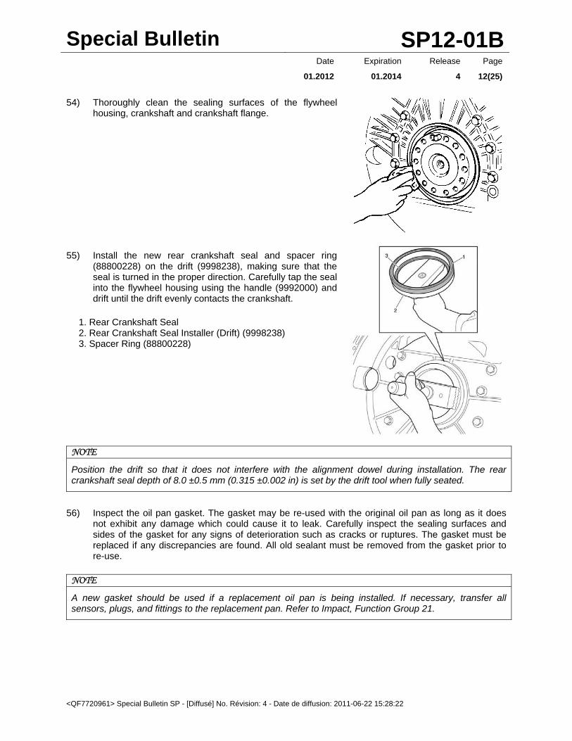
54) Thoroughly clean the sealing surfaces of the flywheel housing, crankshaft and crankshaft flange.
55) Install the new rear crankshaft seal and spacer ring (88800228) on the drift (9998238), making sure that the seal is turned in the proper direction. Carefully tap the seal into the flywheel housing using the handle (9992000) and drift until the drift evenly contacts the crankshaft.
1. Rear Crankshaft Seal 2. Rear Crankshaft Seal Installer (Drift) (9998238) 3. Spacer Ring (88800228)
NOTE
Position the drift so that it does not interfere with the alignment dowel during installation. The rear crankshaft seal depth of 8.0 ±0.5 mm (0.315 ±0.002 in) is set by the drift tool when fully seated.
56) Inspect the oil pan gasket. The gasket may be re-used with the original oil pan as long as it does not exhibit any damage which could cause it to leak. Carefully inspect the sealing surfaces and sides of the gasket for any signs of deterioration such as cracks or ruptures. The gasket must be replaced if any discrepancies are found. All old sealant must be removed from the gasket prior to re-use.
NOTE
A new gasket should be used if a replacement oil pan is being installed. If necessary, transfer all sensors, plugs, and fittings to the replacement pan. Refer to Impact, Function Group 21.
Special Bulletin SP12-01B
<QF7720961> Special Bulletin SP - [Diffusé] No. Révision: 4 - Date de diffusion: 2011-06-22 15:28:22
Date Expiration Release Page
01.2012 01.2014 4 13(25)
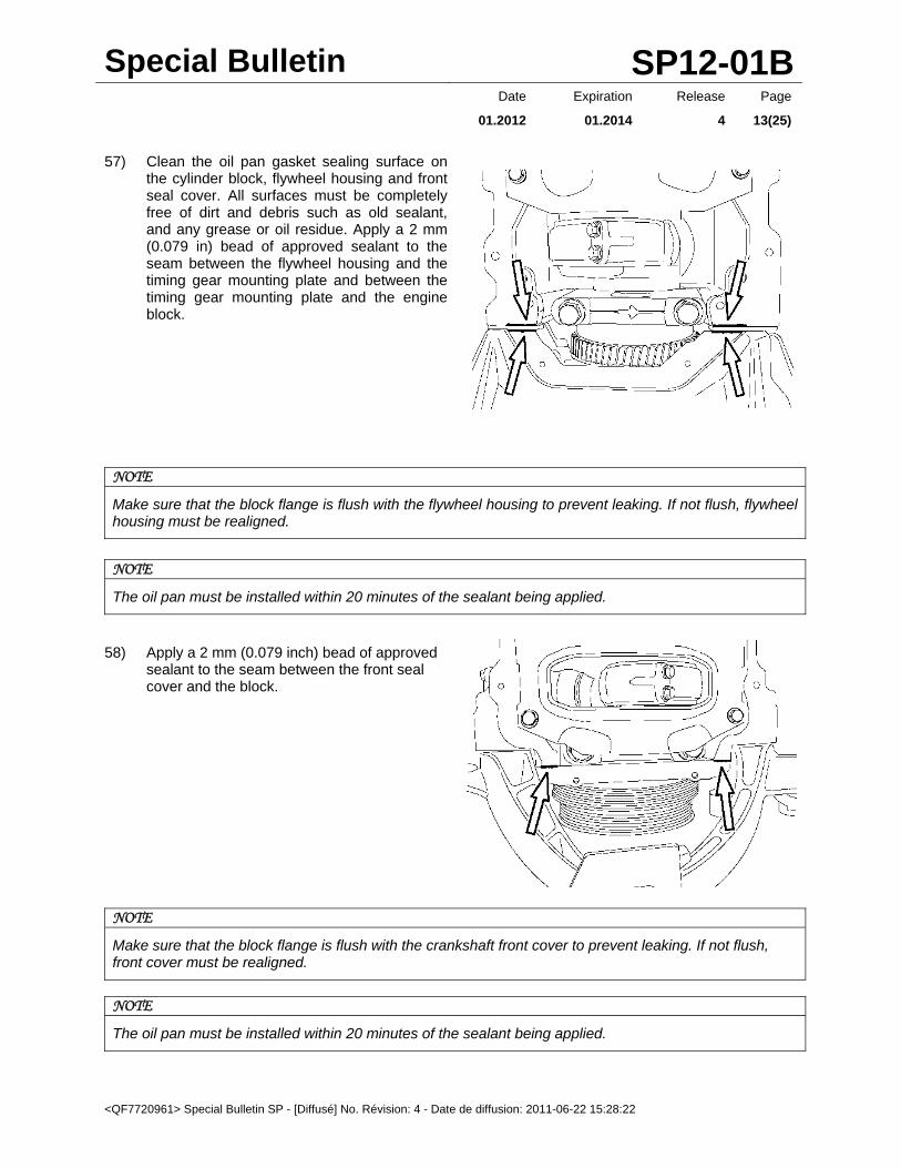
57) Clean the oil pan gasket sealing surface on the cylinder block, flywheel housing and front seal cover. All surfaces must be completely free of dirt and debris such as old sealant, and any grease or oil residue. Apply a 2 mm (0.079 in) bead of approved sealant to the seam between the flywheel housing and the timing gear mounting plate and between the timing gear mounting plate and the engine block.
NOTE
Make sure that the block flange is flush with the flywheel housing to prevent leaking. If not flush, flywheel housing must be realigned.
NOTE
The oil pan must be installed within 20 minutes of the sealant being applied.
58) Apply a 2 mm (0.079 inch) bead of approved sealant to the seam between the front seal cover and the block.
NOTE
Make sure that the block flange is flush with the crankshaft front cover to prevent leaking. If not flush, front cover must be realigned.
NOTE
The oil pan must be installed within 20 minutes of the sealant being applied.

Special Bulletin SP12-01B
<QF7720961> Special Bulletin SP - [Diffusé] No. Révision: 4 - Date de diffusion: 2011-06-22 15:28:22
Date Expiration Release Page
01.2012 01.2014 4 14(25)
59) With assistance, position the oil pan to the engine block and install the fasteners. Tighten bolts to 24 ±4 Nm (18 ±3 ft-lbf).
NOTE
Use care to prevent damage to the oil pickup.
60) Install the dipstick tube. Install oil fill tube. Connect the oil level/temperature sensor connector to the side of the oil pan.
61) If equipped, position the transmission cooler line brackets onto the oil pan fastener studs and install the bracket nuts to secure.
62) Clean all upper timing cover gasket sealing surfaces. All surfaces must be completely free of any grease or oil.
63) Install the timing gear cover seals and gaskets.
64) Apply sealant in the bottom corners where the timing gear plate and the flywheel housing meet. Also apply sealant to the top of the timing gear plate (in the corner) next to the cylinder head.
NOTE
The timing gear cover must be installed within 20 minutes of the sealant being applied.
Special Bulletin SP12-01B
<QF7720961> Special Bulletin SP - [Diffusé] No. Révision: 4 - Date de diffusion: 2011-06-22 15:28:22
Date Expiration Release Page
01.2012 01.2014 4 15(25)
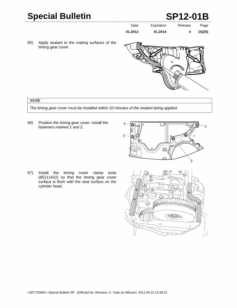
65) Apply sealant to the mating surfaces of the timing gear cover.
NOTE
The timing gear cover must be installed within 20 minutes of the sealant being applied.
66) Position the timing gear cover, install the fasteners marked 1 and 2.
67) Install the timing cover clamp tools (85111422) so that the timing gear cover surface is flush with the seal surface on the cylinder head.

Special Bulletin SP12-01B
<QF7720961> Special Bulletin SP - [Diffusé] No. Révision: 4 - Date de diffusion: 2011-06-22 15:28:22
Date Expiration Release Page
01.2012 01.2014 4 16(25)
68) Tighten the timing gear cover fasteners to 24 ±4 Nm (18 ±3 ft-lbf) in the sequence shown.
69) Inspect the valve cover gasket. The gasket may be reused with the original valve cover as long as it does not exhibit any damage which could cause it to leak. Carefully inspect the sealing surfaces and sides of the gasket for any signs of deterioration such as cracks or ruptures. The gasket must be replaced if any discrepancies are found. All old sealant must be removed from the gasket and the valve cover prior to reuse. A new gasket should be used if a replacement valve cover is being installed.
70) Clean the gasket sealing surface of the cylinder head. The surfaces should be clear of any dirt or debris and free of any oil.
71) Apply a 2 mm (0.079 in) bead of approved sealant to the area where the timing cover and the cylinder head meet. This parting line is on both sides of the cylinder head. Carefully position the valve cover on the cylinder head and make sure that the seal remains properly seated.
NOTE
The valve cover must be installed within 20 minutes of the sealant being applied.
72) Install the valve cover fasteners. Tighten fasteners to 24 ±4 Nm (18 ±3 ft-lbf) in the sequence shown.

Special Bulletin SP12-01B
<QF7720961> Special Bulletin SP - [Diffusé] No. Révision: 4 - Date de diffusion: 2011-06-22 15:28:22
Date Expiration Release Page
01.2012 01.2014 4 17(25)
73) Using a new O-ring, install the fasteners securing crankcase breather tube and bracket to valve cover and intake manifold. Tighten fasteners to 24 ±4 Nm (18 ±3 ft-lbf).
NOTE
Ensure that the same bolts that were removed at disassembly are reinstalled in the same location. Damage to the valve cover will result if the bolts installed are too long.
Special Bulletin SP12-01B
<QF7720961> Special Bulletin SP - [Diffusé] No. Révision: 4 - Date de diffusion: 2011-06-22 15:28:22
Date Expiration Release Page
01.2012 01.2014 4 18(25)
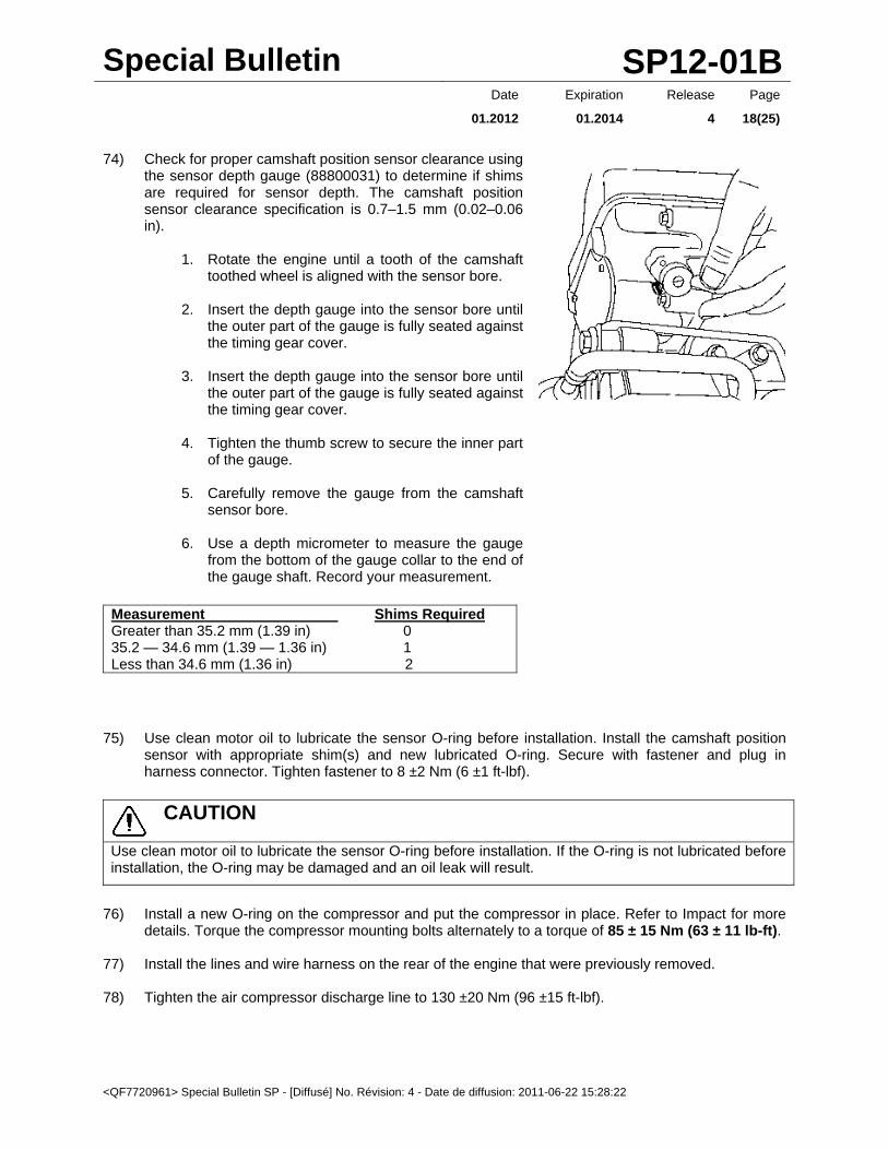
74) Check for proper camshaft position sensor clearance using the sensor depth gauge (88800031) to determine if shims are required for sensor depth. The camshaft position sensor clearance specification is 0.7–1.5 mm (0.02–0.06 in).
1. Rotate the engine until a tooth of the camshaft toothed wheel is aligned with the sensor bore.
2. Insert the depth gauge into the sensor bore until
the outer part of the gauge is fully seated against the timing gear cover.
3. Insert the depth gauge into the sensor bore until
the outer part of the gauge is fully seated against the timing gear cover.
4. Tighten the thumb screw to secure the inner part
of the gauge.
5. Carefully remove the gauge from the camshaft sensor bore.
6. Use a depth micrometer to measure the gauge
from the bottom of the gauge collar to the end of the gauge shaft. Record your measurement.
Measurement Shims Required Greater than 35.2 mm (1.39 in) 0 35.2 — 34.6 mm (1.39 — 1.36 in) 1 Less than 34.6 mm (1.36 in) 2
75) Use clean motor oil to lubricate the sensor O-ring before installation. Install the camshaft position sensor with appropriate shim(s) and new lubricated O-ring. Secure with fastener and plug in harness connector. Tighten fastener to 8 ±2 Nm (6 ±1 ft-lbf).
CAUTION
Use clean motor oil to lubricate the sensor O-ring before installation. If the O-ring is not lubricated before installation, the O-ring may be damaged and an oil leak will result.
76) Install a new O-ring on the compressor and put the compressor in place. Refer to Impact for more
details. Torque the compressor mounting bolts alternately to a torque of 85 ± 15 Nm (63 ± 11 lb-ft).
77) Install the lines and wire harness on the rear of the engine that were previously removed.
78) Tighten the air compressor discharge line to 130 ±20 Nm (96 ±15 ft-lbf).
Special Bulletin SP12-01B
<QF7720961> Special Bulletin SP - [Diffusé] No. Révision: 4 - Date de diffusion: 2011-06-22 15:28:22
Date Expiration Release Page
01.2012 01.2014 4 19(25)
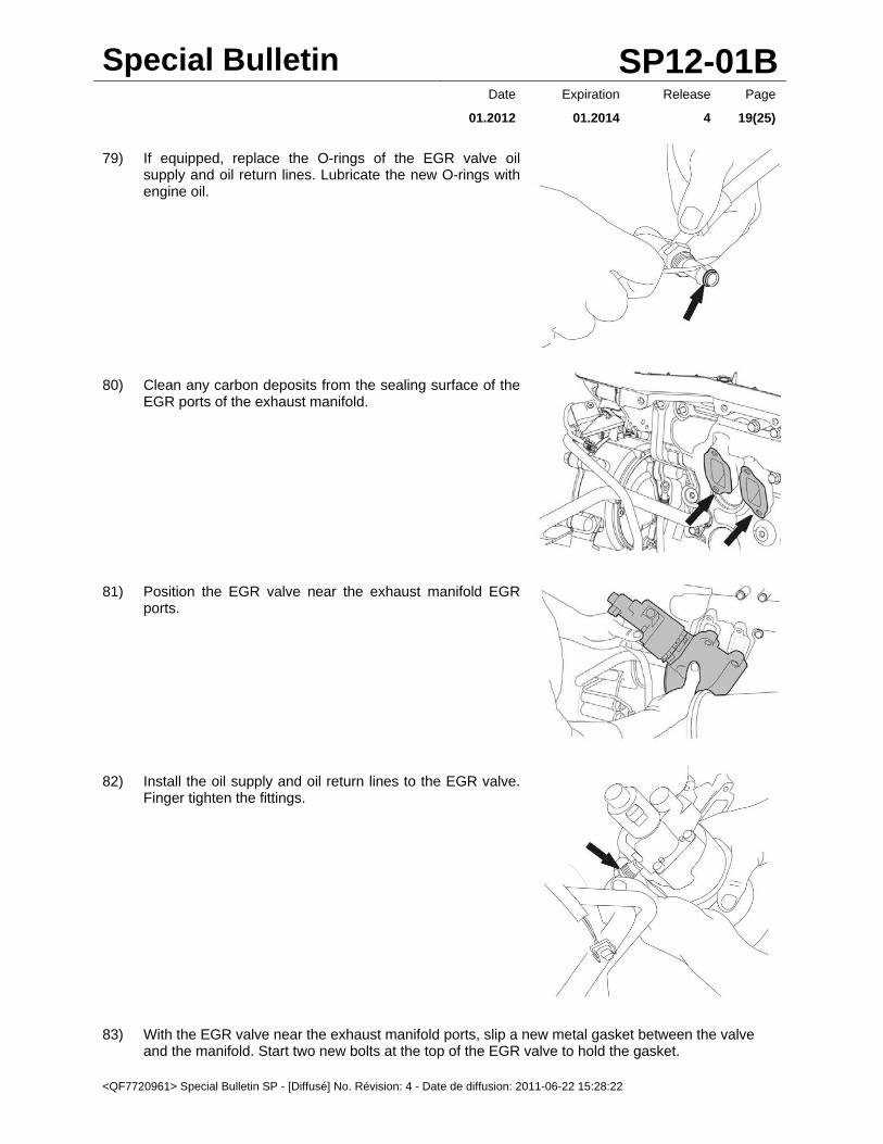
79) If equipped, replace the O-rings of the EGR valve oil supply and oil return lines. Lubricate the new O-rings with engine oil.
80) Clean any carbon deposits from the sealing surface of the EGR ports of the exhaust manifold.
81) Position the EGR valve near the exhaust manifold EGR ports.
82) Install the oil supply and oil return lines to the EGR valve. Finger tighten the fittings.
83) With the EGR valve near the exhaust manifold ports, slip a new metal gasket between the valve and the manifold. Start two new bolts at the top of the EGR valve to hold the gasket.

Special Bulletin SP12-01B
<QF7720961> Special Bulletin SP - [Diffusé] No. Révision: 4 - Date de diffusion: 2011-06-22 15:28:22
Date Expiration Release Page
01.2012 01.2014 4 20(25)
NOTE
Apply anti-seize compound to the threads and under the heads or contact surfaces of the fasteners. Anti-seize helps prevent fastener corrosion and reduces friction to help achieve the intended clamp load on the component with tightening the fasteners to specification.
84) Start the two remaining new EGR valve bolts.
NOTE
Apply anti-seize compound to the threads and under the heads or contact surfaces of the fasteners.
85) Tighten the oil supply line to secure.
86) Use special tool (88800217) to tighten the EGR valve oil return line.
87) Tighten the EGR valve mounting bolts diagonally to 20 ±4 Nm (15 ±3 ft-lbf, then tighten to 61 ±3 Nm (45 ±4 ft-lbf).
88) Connect the wiring harness connector to the EGR valve.
89) Install new high temperature gaskets into the EGR valve end of
the hot pipe and the inlet of the EGR cooler. Ensure the gaskets lay flat against the flange surfaces with the bead of the gaskets facing toward the hot pipe.
Special Bulletin SP12-01B
<QF7720961> Special Bulletin SP - [Diffusé] No. Révision: 4 - Date de diffusion: 2011-06-22 15:28:22
Date Expiration Release Page
01.2012 01.2014 4 21(25)
NOTE
These gaskets are one-time use only. Do not reuse the gaskets.
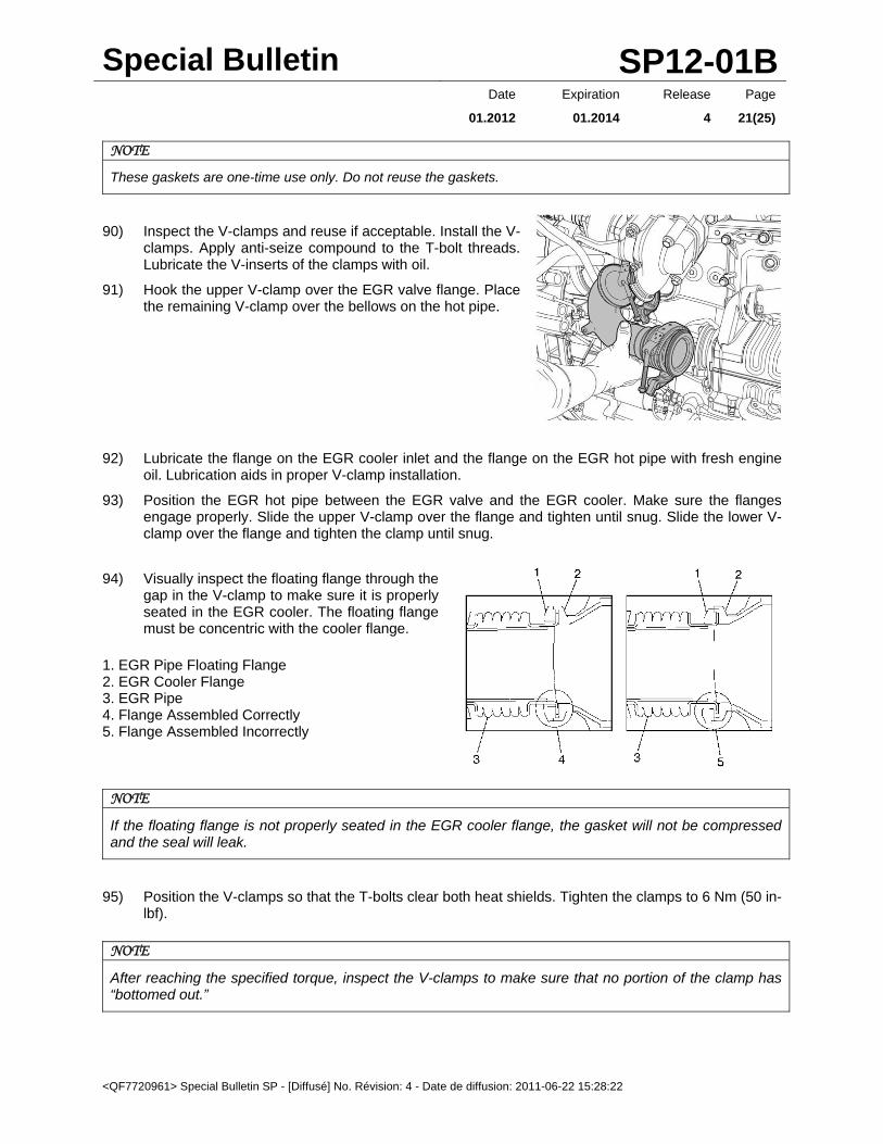
90) Inspect the V-clamps and reuse if acceptable. Install the V-clamps. Apply anti-seize compound to the T-bolt threads. Lubricate the V-inserts of the clamps with oil.
91) Hook the upper V-clamp over the EGR valve flange. Place the remaining V-clamp over the bellows on the hot pipe.
92) Lubricate the flange on the EGR cooler inlet and the flange on the EGR hot pipe with fresh engine oil. Lubrication aids in proper V-clamp installation.
93) Position the EGR hot pipe between the EGR valve and the EGR cooler. Make sure the flanges engage properly. Slide the upper V-clamp over the flange and tighten until snug. Slide the lower V-clamp over the flange and tighten the clamp until snug.
94) Visually inspect the floating flange through the gap in the V-clamp to make sure it is properly seated in the EGR cooler. The floating flange must be concentric with the cooler flange.
1. EGR Pipe Floating Flange 2. EGR Cooler Flange 3. EGR Pipe 4. Flange Assembled Correctly 5. Flange Assembled Incorrectly
NOTE
If the floating flange is not properly seated in the EGR cooler flange, the gasket will not be compressed and the seal will leak.
95) Position the V-clamps so that the T-bolts clear both heat shields. Tighten the clamps to 6 Nm (50 in-lbf).
NOTE
After reaching the specified torque, inspect the V-clamps to make sure that no portion of the clamp has “bottomed out.”

Special Bulletin SP12-01B
<QF7720961> Special Bulletin SP - [Diffusé] No. Révision: 4 - Date de diffusion: 2011-06-22 15:28:22
Date Expiration Release Page
01.2012 01.2014 4 22(25)
96) Place the EGR heat shield in position over the EGR valve, if equipped. Install the fasteners to secure the shield to the cylinder block and to the studs on the valve mounting bolt heads.
97) Position the EGR crossover pipe (with new O-rings) between the venturi outlet pipe and the mixer inlet pipe.
1. Venturi Outlet Pipe 2. Crossover Pipe 3. Mixer Inlet Pipe
98) Make sure the O-rings are in place and install the V-clamps at both ends of the crossover pipe. Tighten the clamps to specification.
99) Install a new gasket at the diffuser. Position the diffuser against the turbocharger and install the V-clamp. Tighten the V-clamp to 12 ±2 Nm (9 ±1.5 ft-lbf).
100) Connect fuel line to aftertreatment injector. Tighten to 15 ±2 Nm (135 ±18 in-lbf). If equipped, connect air line and coolant lines to aftertreatment injector. Tighten air line to 27 Nm (20 ft-lbf). Tighten coolant lines to 48 ±5 Nm (35 ±4 ft-lbf).
CAUTION
Do not kink the fuel and coolant lines. Kinking the lines may result in leakage.

Special Bulletin SP12-01B
<QF7720961> Special Bulletin SP - [Diffusé] No. Révision: 4 - Date de diffusion: 2011-06-22 15:28:22
Date Expiration Release Page
01.2012 01.2014 4 23(25)
101) Connect crossover pipe to air compressor.
102) Clean the surface in the places where the flywheel lies flush against the crankshaft gear wheel. Clean the flywheel. Check that the grooved surfaces for the flywheel sensor are clean.
103) Make sure that the flywheel guide pin is correctly inserted in the crankshaft gearwheel. Ensure that there is no damage or leakage at the rear crankshaft seal.
104) Lift the flywheel with the aid of the 2 bolts (M10 x 100 mm) and screw in the mounting bolts.
105) Install the cranking tool (88800014) and a pull handle as a counter hold.
106) Tighten the flywheel mounting bolts in accordance with the tightening diagram to 60 ±5 Nm (44 ±4 ft-lbf), then 120 ± 10 degrees.
107) Remove the cranking tool (88800014). Insert the plug.
108) Using a new sealing ring, install the crankshaft sensor. Tighten the fastener to 8 ±2 Nm (6 ±1 ft-lbf).
Special Bulletin SP12-01B
<QF7720961> Special Bulletin SP - [Diffusé] No. Révision: 4 - Date de diffusion: 2011-06-22 15:28:22
Date Expiration Release Page
01.2012 01.2014 4 24(25)
109) Align and install the clutch and pressure plate. Tighten the pressure plate fasteners.
NOTE
Remove the pressure plate locking fasteners, if applicable.
110) With assistance, install the transmission. Refer to Impact, Function Group 43.
111) Mount and secure clutch slave cylinder. Secure line bracket at rear of transmission.
112) Install the release bearing lubrication line, make sure it does not become damaged when tightening.
113) Install the transmission oil cooler lines. Install the brackets securing the lines.
114) Route and secure the battery cables and wire harness to starter.
115) Install starter motor. Tighten cables securely. Secure harness with clamps and cable ties.
116) Secure all harnesses with cable ties.
117) Install engine and transmission in vehicle. Refer to Impact, Function Group 21.
118) Install all previously removed cables to the ground (negative) battery terminals.
119) Use coolant extractor (85112740) to fill the system with approved coolant per specifications.
120) Fill the engine with the engine oil removed previously.
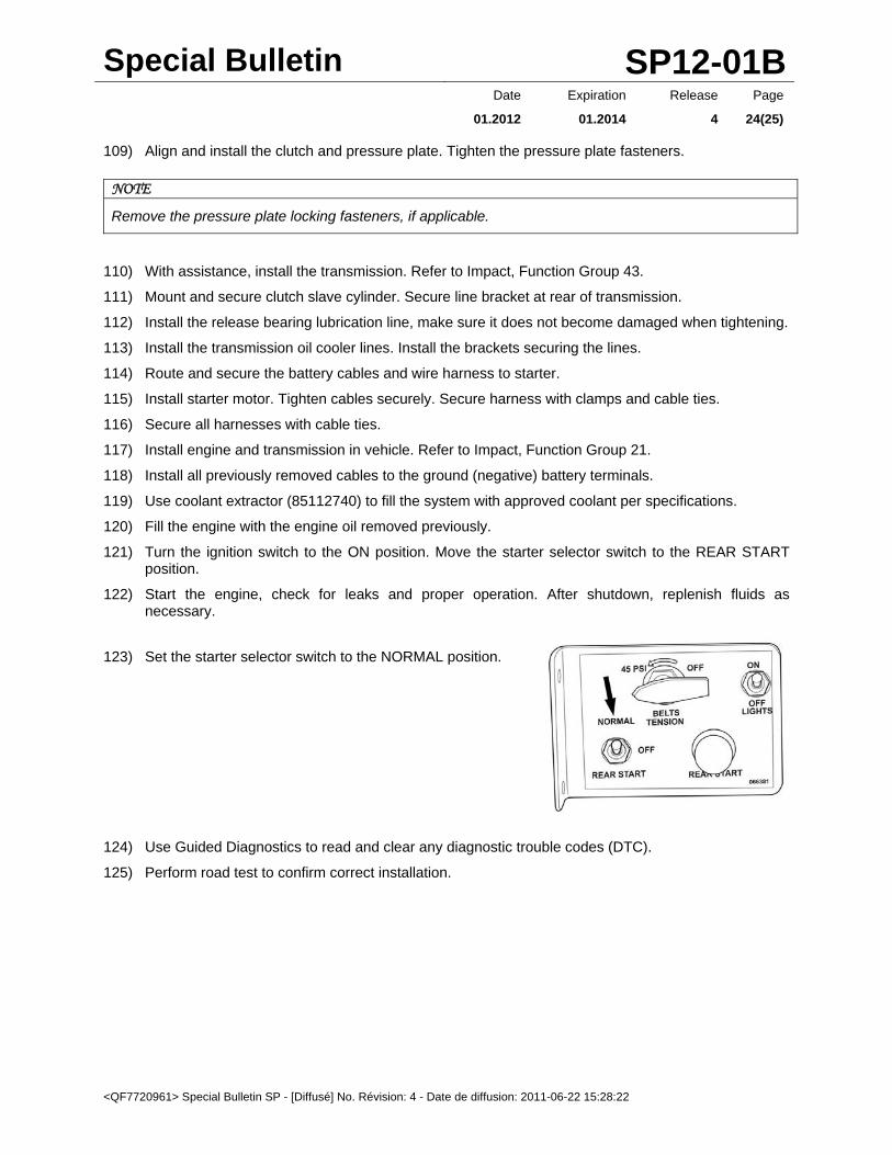
121) Turn the ignition switch to the ON position. Move the starter selector switch to the REAR START position.
122) Start the engine, check for leaks and proper operation. After shutdown, replenish fluids as necessary.
123) Set the starter selector switch to the NORMAL position.
124) Use Guided Diagnostics to read and clear any diagnostic trouble codes (DTC).
125) Perform road test to confirm correct installation.
Special Bulletin SP12-01B
<QF7720961> Special Bulletin SP - [Diffusé] No. Révision: 4 - Date de diffusion: 2011-06-22 15:28:22
Date Expiration Release Page
01.2012 01.2014 4 25(25)
PARTS / WASTE DISPOSAL
Return the double idler gear to Prevost.
WARRANTY
This modification is covered by Prevost’s normal warranty.
The estimated time required to perform Method 2 is approximately 40 hrs.
Please use the standard text SP12-01 with system condition letter “B”. OTHER VBC Bulletin S8748
Fail Code 01.00-2
Defect Code 09
System Condition B
Causal Part 21760930