SolidWorks and - CamInstructor
37
SolidWorks and TRAINING GUIDE MILL-LESSON-4-T OOLPATHS DRILL AND CONTOUR
Transcript of SolidWorks and - CamInstructor


SolidWorks and Mastercam Training Guide
Mastercam Mill-Lesson-4-37
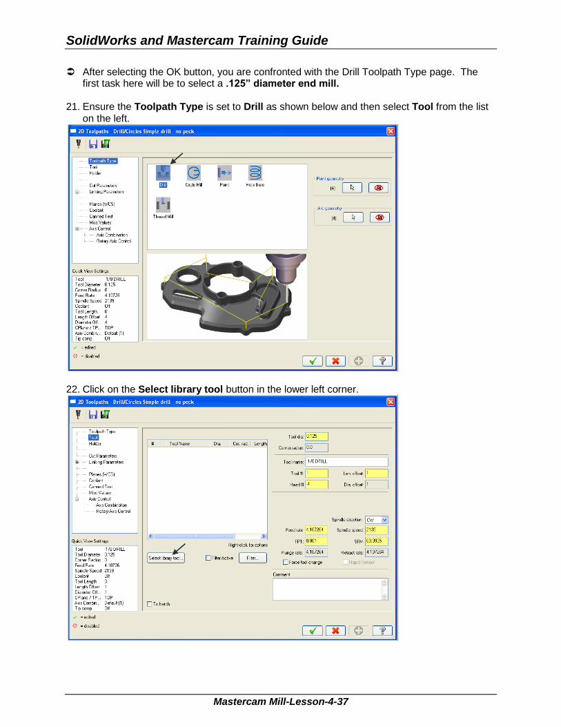
After selecting the OK button, you are confronted with the Drill Toolpath Type page. The first task here will be to select a .125” diameter end mill.
21. Ensure the Toolpath Type is set to Drill as shown below and then select Tool from the list
on the left.
22. Click on the Select library tool button in the lower left corner.

Mill-Lesson-4
Mastercam Mill-Lesson-4-38
23. On the right hand side of the Tool Selection dialog box remove the green check mark from the Filter Active to review all the tools.
24. Use the slider bar on the right of this dialog box to scroll down and locate a .125” diameter
flat end mill. 25. Select the .125” diameter flat end mill by picking anywhere along the .125 end mill row, as
shown below:
26. To resize a column in the Tool Selection dialog box, click on the divider between the
columns with your left mouse button, as shown below, hold the left mouse button down and move to the right or left.
27. Select the OK button to complete the selection of this tool. Sample
not for
Distrib
ution
SolidWorks and Mastercam Training Guide
Mastercam Mill-Lesson-4-39
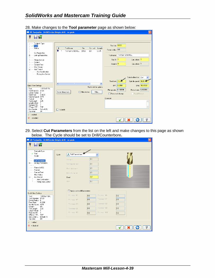
28. Make changes to the Tool parameter page as shown below:
29. Select Cut Parameters from the list on the left and make changes to this page as shown
below. The Cycle should be set to Drill/Counterbore.
Sample
not for
Distrib
ution

Mill-Lesson-4
Mastercam Mill-Lesson-4-40
30. Select Linking Parameters from the list on the left and make changes to this page as shown below. Input the depth of -0.28 and the other values as shown below. Note all the values are set to Absolute.
31. Select the plus sign to the left of Linking Parameters to expand the list and click on Tip
Comp.
32. Ensure Tip Comp is not activated as shown below. The Tip Comp box is empty. The red
circular icon denotes this option is disabled.
Sample
not for
Distrib
ution

SolidWorks and Mastercam Training Guide
Mastercam Mill-Lesson-4-41
33. Select Coolant from the list on the left. Open up the drop down menu for Flood and set it to On.
34. Select the OK button to complete this function. 35. Your part should look like the screenshot below:
Sample
not for
Distrib
ution

Mill-Lesson-4
Mastercam Mill-Lesson-4-42
TOOLPATH TASK 5: MACHINE THE CONTOUR. In this task you machine the contour with a .5” diameter 2 flute end mill. Initially you will machine the contour in one cut at a depth of -.125” and then later in this
Lesson add roughing and finishing cuts using Depth of Cuts and Multi Passes. 1. From the menu bar select Toolpaths>Contour…
2. On the screen you will now see the Chaining dialog box with Chain set and in the graphics
screen a prompt to “Select Contour chain 1”. Select the top horizontal line as shown below:
Sample
not for
Distrib
ution

SolidWorks and Mastercam Training Guide
Mastercam Mill-Lesson-4-43
3. After selecting the top horizontal line your graphics screen should looks like the screenshot below, with the green arrow pointing to the right, clockwise direction.
The material for this part is aluminium so to attain a good finish when contouring climb milling should be employed.
4. If the arrow is not pointing to the right select the arrow from the Chaining dialog box shown
below to reverse the direction:
5. After the contour has been successfully chained select the OK button at the bottom of the Chaining dialog box.
Sample
not for
Distrib
ution
Mill-Lesson-4
Mastercam Mill-Lesson-4-44
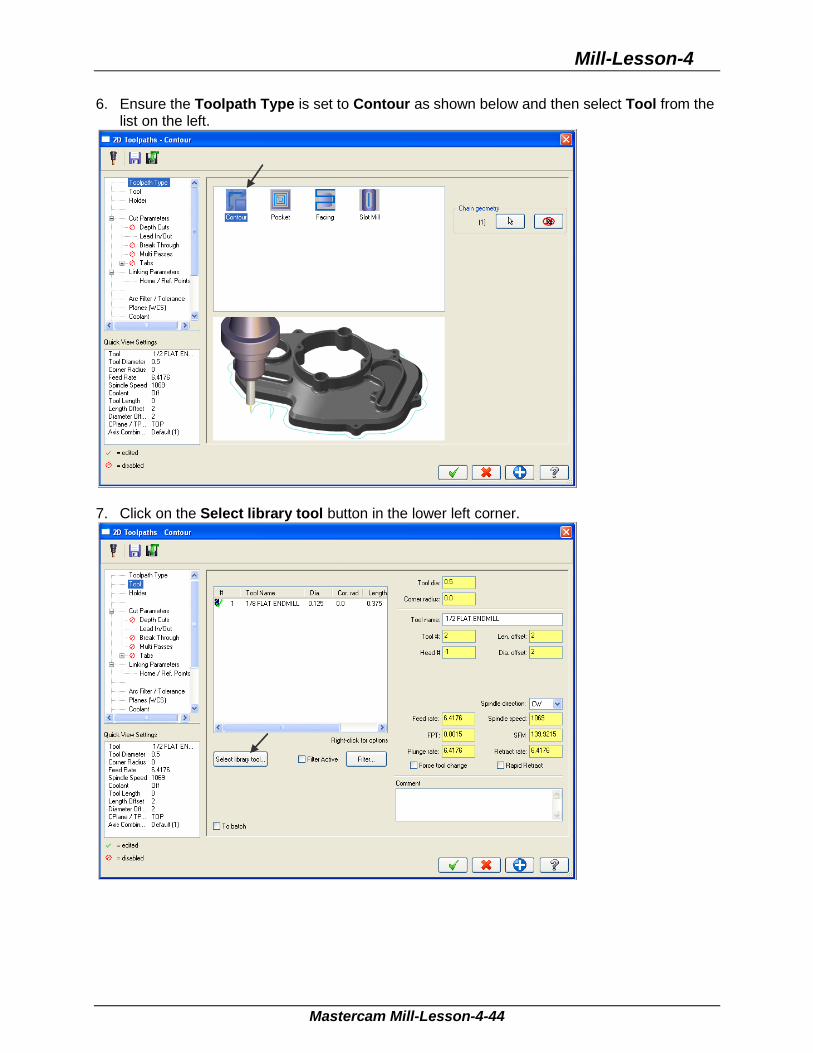
6. Ensure the Toolpath Type is set to Contour as shown below and then select Tool from the list on the left.
7. Click on the Select library tool button in the lower left corner.
Sample
not for
Distrib
ution

SolidWorks and Mastercam Training Guide
Mastercam Mill-Lesson-4-45
8. Use the slider bar on the right of this dialog box to scroll down and locate a .5” diameter flat end mill. Select the .5” diameter flat end mill by picking anywhere along the .5 end mill row, as shown below:
9. Select the OK button to complete the selection of this tool. 10. Make changes to the Tool page as shown below:
Sam
ple
not for
Distrib
ution
Mill-Lesson-4
Mastercam Mill-Lesson-4-46
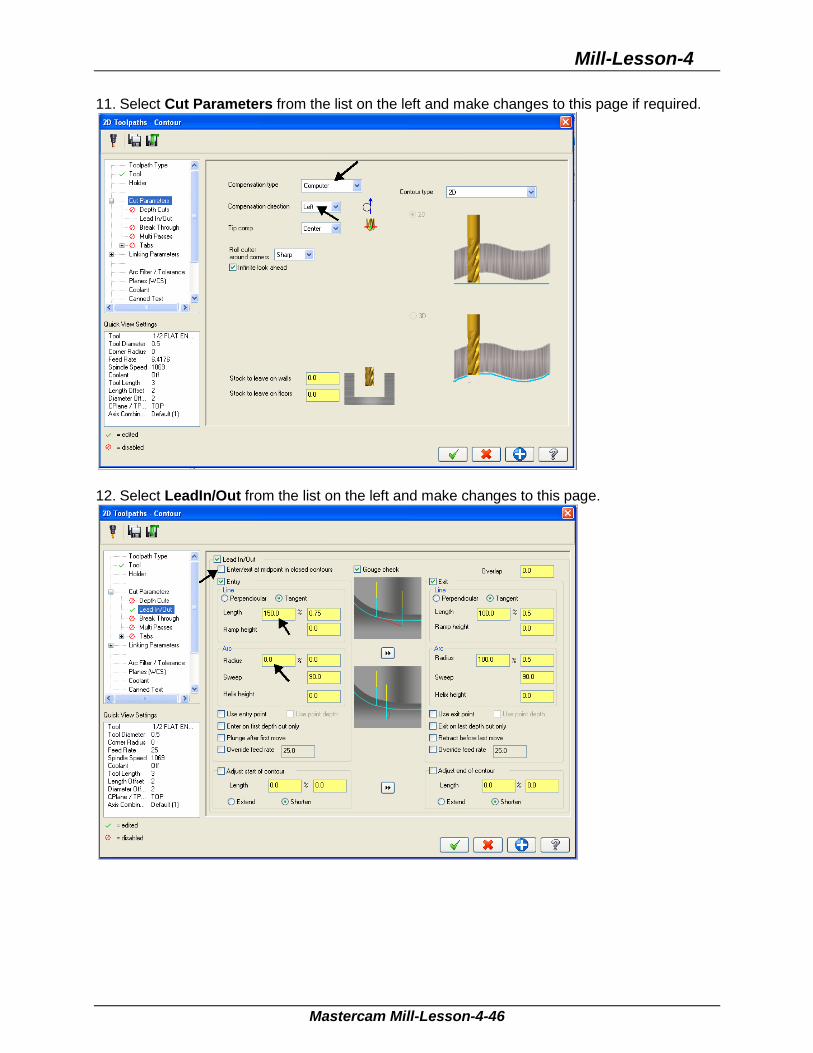
11. Select Cut Parameters from the list on the left and make changes to this page if required.
12. Select LeadIn/Out from the list on the left and make changes to this page.
Sample
not for
Distrib
ution
SolidWorks and Mastercam Training Guide
Mastercam Mill-Lesson-4-47
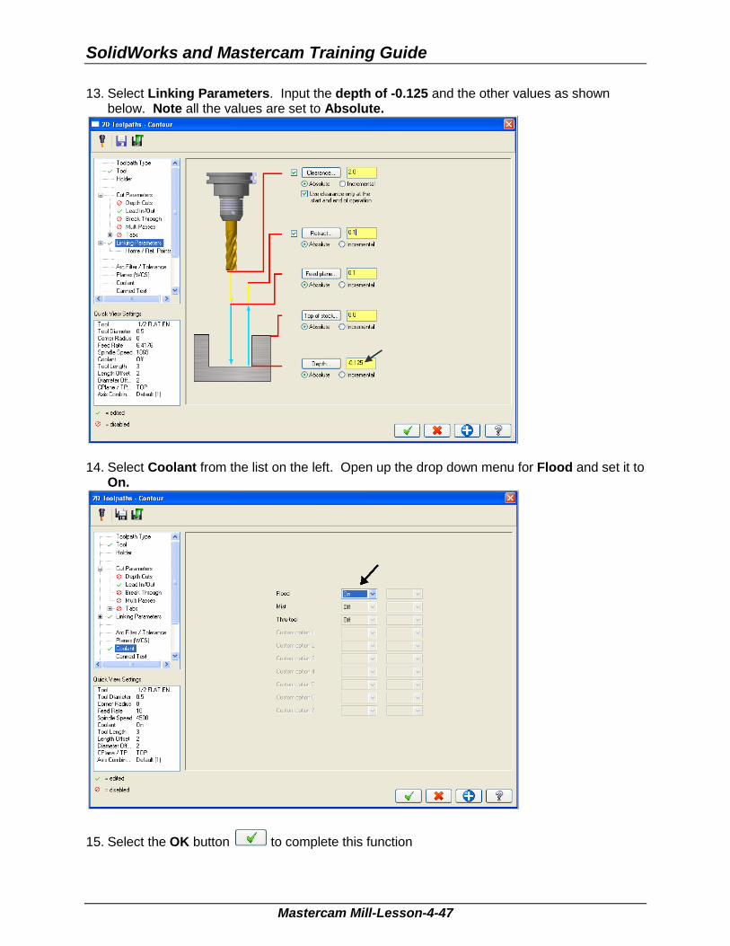
13. Select Linking Parameters. Input the depth of -0.125 and the other values as shown below. Note all the values are set to Absolute.
14. Select Coolant from the list on the left. Open up the drop down menu for Flood and set it to
On.
15. Select the OK button to complete this function
Sample
not for
Distrib
ution

Mill-Lesson-4
Mastercam Mill-Lesson-4-48
TOOLPATH TASK 6: BACKPLOT THE TOOLPATH In this task you will use Mastercam’s Backplot function to view the path the tools take to cut
this part. Backplot will enable you to review the cutting motions and identify any problem areas when
cutting the part. When the toolpaths are being Backplotted Mastercam displays tool path information on the
right of the screen. Information such as the current tool position in X, Y, and Z coordinates. For more information on Backplot see the Tips and Techniques section on the
multimedia DVD supplied with this text.
1. To pick all the operations to backplot pick the Select All icon circled below:
Another method to Select all the operations is by clicking on the Toolpath Group-1 in the
Tool Manager as shown by the arrow above. 2. The next step is to select the Backplot selected operations icon shown below:
3. Maximize the Backplot/Verify window if required. 4. Select the Home Tab if required.
5. At the top of the screen select the Isometric icon and then select Fit.
Sample
not for
Distrib
ution

SolidWorks and Mastercam Training Guide
Mastercam Mill-Lesson-4-49
4. Activate the options shown below in the Visibility section of the Home tab.
6. Click on the Backplot tab at the top left of the screen
7. Activate the Both option in the Toolpath section of the Backplot tab.
8. In the lower right corner of the screen now set the run Speed to slow by moving the slider
bar pointer over to the left as shown below.
9. Now select the Play Simulation button to review the toolpaths.
10. After reviewing the backplot of the two toolpaths using a .125” and .5” end mill select the
Close button to exit Backplot.
Sample
not for
Distrib
ution

Mill-Lesson-4
Mastercam Mill-Lesson-4-50
TOOLPATH TASK 7: MODIFY THE CONTOUR TOOLPATH TO ADD ROUGHING CUTS AND A FINISH PASS In this task you will use Mastercam’s Multi Passes and Depth of cuts to perform a
roughing and finishing operation for the contour toolpath. Multi Passes will let the tool approach the part geometry at the cutting depth in steps
instead of cutting right to the part geometry. Depth of cuts can be used to set the number of depth cuts, you can enter a maximum
rough step and Mastercam divides the total depth into equal steps. Or you can enter the exact number of finish steps and the size of each finish step. Mastercam never creates unequal rough depth cuts.
For more information on Multi Passes and Depth of cuts see the Tips and Techniques section on the multimedia CD supplied with this text.
1. In the Toolpaths Manager select Parameters from the contour toolpath as shown below:
Sam
ple
not for
Distrib
ution
SolidWorks and Mastercam Training Guide
Mastercam Mill-Lesson-4-51
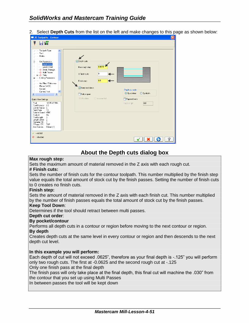
2. Select Depth Cuts from the list on the left and make changes to this page as shown below:
About the Depth cuts dialog box Max rough step: Sets the maximum amount of material removed in the Z axis with each rough cut. # Finish cuts: Sets the number of finish cuts for the contour toolpath. This number multiplied by the finish step value equals the total amount of stock cut by the finish passes. Setting the number of finish cuts to 0 creates no finish cuts. Finish step: Sets the amount of material removed in the Z axis with each finish cut. This number multiplied by the number of finish passes equals the total amount of stock cut by the finish passes. Keep Tool Down: Determines if the tool should retract between multi passes. Depth cut order: By pocket/contour Performs all depth cuts in a contour or region before moving to the next contour or region. By depth Creates depth cuts at the same level in every contour or region and then descends to the next depth cut level. In this example you will perform: Each depth of cut will not exceed .0625”, therefore as your final depth is -.125” you will perform only two rough cuts. The first at -0.0625 and the second rough cut at -.125 Only one finish pass at the final depth The finish pass will only take place at the final depth, this final cut will machine the .030” from the contour that you set up using Multi Passes In between passes the tool will be kept down
Sample
not for
Distrib
ution

Mill-Lesson-4
Mastercam Mill-Lesson-4-52
3. Select Multi Passes from the list on the left and make changes to this page as shown below:
About the Multi Passes dialog box Roughing passes: Number: Enter the number of cutting passes you want Mastercam to create. Spacing: Enter the amount of stock to remove with each cut. Finishing passes: Number: Enter the number of cutting passes you want Mastercam to create. Spacing: Enter the amount of stock to remove with each cut. Machine finish Passes at: Final Depth: Performs a single finish pass at the final depth. Keep Tool Down: Determines whatever the tool should retract between multi passes. In this example you will perform: No roughing cuts in the XY pane. Only one finish pass at the final depth. While cutting at the various depths you will stay .030” away from the contour. The finish pass will take place at the final depth. In between passes the tool will be kept down.
4. After reviewing the values input in the Multi Passes dialog box select the OK button to exit.
Sample
not for
Distrib
ution

SolidWorks and Mastercam Training Guide
Mastercam Mill-Lesson-4-53
5. Select the Regenerate all dirty operations icon to remove the red X from the contouring operation you have just edited. You need to update the toolpath with the new parameters you have just input.
Dirty toolpath This happens if you have changed certain parameters of the underlying geometry, or in this example you have updated the contour toolpaths to use Depth of cuts and multi passes. Toolpaths can be regenerated by clicking the Regenerate button at the top of the Toolpaths Manager circled above.
Sample
not for
Distrib
ution

Mill-Lesson-4
Mastercam Mill-Lesson-4-54
TOOLPATH TASK 8: VERIFY THE TOOLPATH Mastercam's Verify utility allows you to use solid models to simulate the machining of a part.
The model created by the verification represents the surface finish, and shows collisions, if any exist.
This allows you to identify and correct program errors before they reach the shop floor. Backplot and Verify are very similar. The differences between these two functions are that
Backplot offers basic simulation options. Whereas Verify offers material removal, collision checking and precision control.
For more information on Verify see the Tips and Techniques section on the multimedia DVD supplied with this text
1. In the Toolpaths Manager pick all the operations to verify by picking the Select All icon
. 1. Select the Verify selected operations icon shown below:
2. Maximize the Backplot/Verify window if required. 3. At the top of the screen select the Isometric icon and then select Fit.
5. Activate the options shown below in the Visibility section of the Home tab. Initial Stock not
activated.
6. In the lower right corner of the screen now set the run Speed to slow by moving the slider
bar pointer over to the left as shown below.
7. Now select the Play Simulation button to review the toolpaths.
Sample
not for
Distrib
ution

SolidWorks and Mastercam Training Guide
Mastercam Mill-Lesson-4-55
8. After reviewing the two toolpaths the verified toolpaths should appear as in the picture below.
9. Select the Close button in the top right hand corner to exit Verify.
TOOLPATH TASK 9: SAVE THE UPDATED MASTERCAM FILE
1. Select the save icon from the toolbar . Sam
ple
not for
Distrib
ution
Mill-Lesson-4
Mastercam Mill-Lesson-4-56
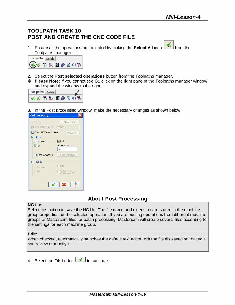
TOOLPATH TASK 10: POST AND CREATE THE CNC CODE FILE
1. Ensure all the operations are selected by picking the Select All icon from the Toolpaths manager.
2. Select the Post selected operations button from the Toolpaths manager. Please Note: If you cannot see G1 click on the right pane of the Toolpaths manager window
and expand the window to the right.
3. In the Post processing window, make the necessary changes as shown below:
About Post Processing NC file: Select this option to save the NC file. The file name and extension are stored in the machine group properties for the selected operation. If you are posting operations from different machine groups or Mastercam files, or batch processing, Mastercam will create several files according to the settings for each machine group. Edit: When checked, automatically launches the default text editor with the file displayed so that you can review or modify it.
4. Select the OK button to continue.
Sample
not for
Distrib
ution

SolidWorks and Mastercam Training Guide
Mastercam Mill-Lesson-4-57
5. Ensure the same name as your Mastercam part file name is displayed in the NC File name field as shown below:
6. Select the Save button. 7. The CNC code file opens up in the default editor.
8. Select the in the top right corner to exit the CNC editor. 9. This completes Mill-Lesson-4.
Sample
not for
Distrib
ution

Mill-Lesson-4
Mastercam Mill-Lesson-4-58
MILL-LESSON-4 EXERCISES
Sample
not for
Distrib
ution

SolidWorks and Mastercam Training Guide
Mastercam Mill-Lesson-4-59
Sample
not for
Distrib
ution

Mill-Lesson-4
Mastercam Mill-Lesson-4-60
Sample
not for
Distrib
ution