Solar Resource Mapping in Vietnam IMPLEMENTATION...
44
Solar Resource Mapping in Vietnam IMPLEMENTATION PLAN MAY 2017 Public Disclosure Authorized Public Disclosure Authorized Public Disclosure Authorized Public Disclosure Authorized
Transcript of Solar Resource Mapping in Vietnam IMPLEMENTATION...

Solar Resource Mapping in Vietnam
IMPLEMENTATION PLAN MAY 2017
Pub
lic D
iscl
osur
e A
utho
rized
Pub
lic D
iscl
osur
e A
utho
rized
Pub
lic D
iscl
osur
e A
utho
rized
Pub
lic D
iscl
osur
e A
utho
rized

This report was prepared by Suntrace, under contract to The World Bank.
Energy Resource Mapping and Geospatial Planning Vietnam [Project ID: P145513]. This activity is funded and supported by the Energy Sector Management Assistance Program (ESMAP), a multi-donor trust fund administered by The World Bank, under a global initiative on Renewable Energy Resource Mapping. Further details on the initiative can be obtained from the ESMAP website.
This report is an interim output from the above-mentioned project. Users are strongly advised to exercise caution when utilizing the information and data contained, as this has not been subject to validation using ground measurement data or peer review. The final output from this project will be a validated Vietnam Solar Atlas, which will be published once the project is completed.
To obtain additional maps and information on solar resources globally, please visit:
http://globalsolaratlas.info
Copyright © 2017 THE WORLD BANK Washington DC 20433 Telephone: +1-202-473-1000 Internet: www.worldbank.org
The World Bank, comprising the International Bank for Reconstruction and Development (IBRD) and the International Development Association (IDA), is the commissioning agent and copyright holder for this publication. However, this work is a product of the consultants listed, and not of World Bank staff. The findings, interpretations, and conclusions expressed in this work do not necessarily reflect the views of The World Bank, its Board of Executive Directors, or the governments they represent.
The World Bank does not guarantee the accuracy of the data included in this work and accept no responsibility for any consequence of their use. The boundaries, colors, denominations, and other information shown on any map in this work do not imply any judgment on the part of The World Bank concerning the legal status of any territory or the endorsement or acceptance of such boundaries.
The material in this work is subject to copyright. Because The World Bank encourages dissemination of its knowledge, this work may be reproduced, in whole or in part, for non-commercial purposes as long as full attribution to this work is given. Any queries on rights and licenses, including subsidiary rights, should be addressed to World Bank Publications, The World Bank Group, 1818 H Street NW, Washington, DC 20433, USA; fax: +1-202-522-2625; e-mail: [email protected]. Furthermore, the ESMAP Program Manager would appreciate receiving a copy of the publication that uses this publication for its source sent in care of the address above, or to [email protected].
SOLAR MEASUREMENT CAMPAIGN IN VIETNAM SELECTION #: 1231900 Implementation Plan
23 May 2017
World Bank Group
ESMAP Renewable Energy Mapping Initiative
Lead contractor: Suntrace GmbH
Grosse Elbstrasse 145c 22767 Hamburg Germany E: [email protected] W: www.suntrace.de
Subcontractor: Vietnam Applied Technical Co. Ltd
60B/5 Thai Nguyen, Phuong Saiward Nha Trang City, Khanh Hoa Province, Vietnam E: [email protected] W: www.vatec.vn
IMPLEMENTATION PLAN -‐ VIETNAM (SELECTION # 1231900)
i
Contents
Contents ..................................................................................................................................................................... i 1. Introduction ....................................................................................................................................................... 1
Background .......................................................................................................................................................... 1 Objectives and approach ..................................................................................................................................... 1 Technical Consultations ........................................................................................................................................ 2
2. The project consortium and roles of partners ................................................................................................... 4 Partners and stakeholders involved ...................................................................................................................... 4
International Measurement Experts from Suntrace GmbH .............................................................................. 4 Local Partner: Vietnam Applied Technical Co. Ltd (VATEC) ............................................................................ 4 Project Stakeholders ........................................................................................................................................ 5
3. Solar measurement stations .............................................................................................................................. 6 Final selection of sites .......................................................................................................................................... 6 Solar and meteorological measurement equipment ............................................................................................ 8 General layout of the measurement stations ..................................................................................................... 14 Description of solar measurement sites ............................................................................................................. 18
2.1 Bac Ninh near Hanoi - VNHAN ................................................................................................................ 19 2.2 Da Nang – VNDAN .................................................................................................................................. 21 2.3 Central Highlands – VNCEH .................................................................................................................... 23 2.4 EVN Song Binh – VNSOB ........................................................................................................................ 24 2.5 EVN Tri An dam – VNTRA ....................................................................................................................... 26
4. Tasks and deliverables .................................................................................................................................... 29 Task 2: Procurement of the measurement equipment ....................................................................................... 29 Task 3: Installation and commissioning of the measurement equipment .......................................................... 30 Task 4: Operation and maintenance of the measurement stations .................................................................... 31 Task 5: Regular assessment of data quality and data delivery ........................................................................... 32 Task 6: Capacity building ................................................................................................................................... 32 Task 7: Recalibration of the sensors, handover and wrap-up meeting .............................................................. 33
5. Time table ....................................................................................................................................................... 35 6. Assessment of risks .......................................................................................................................................... 36 7. Permits and import procedure ...................................................................................................................... 38
Permits for private and public station locations ................................................................................................. 38 Import and customs procedure .......................................................................................................................... 38
List of figures ........................................................................................................................................................... 39 List of Tables ........................................................................................................................................................... 40
IMPLEMENTATION PLAN -‐ VIETNAM (SELECTION # 1231900)
1
1. INTRODUCTION
Background This report is prepared within the project Selection # 1231900/ Solar Measurement Campaign in Vietnam. Under
this project a two-year solar measurement campaign as a stand-alone activity funded from a World Bank (WBG)
executed trust fund will be commissioned.
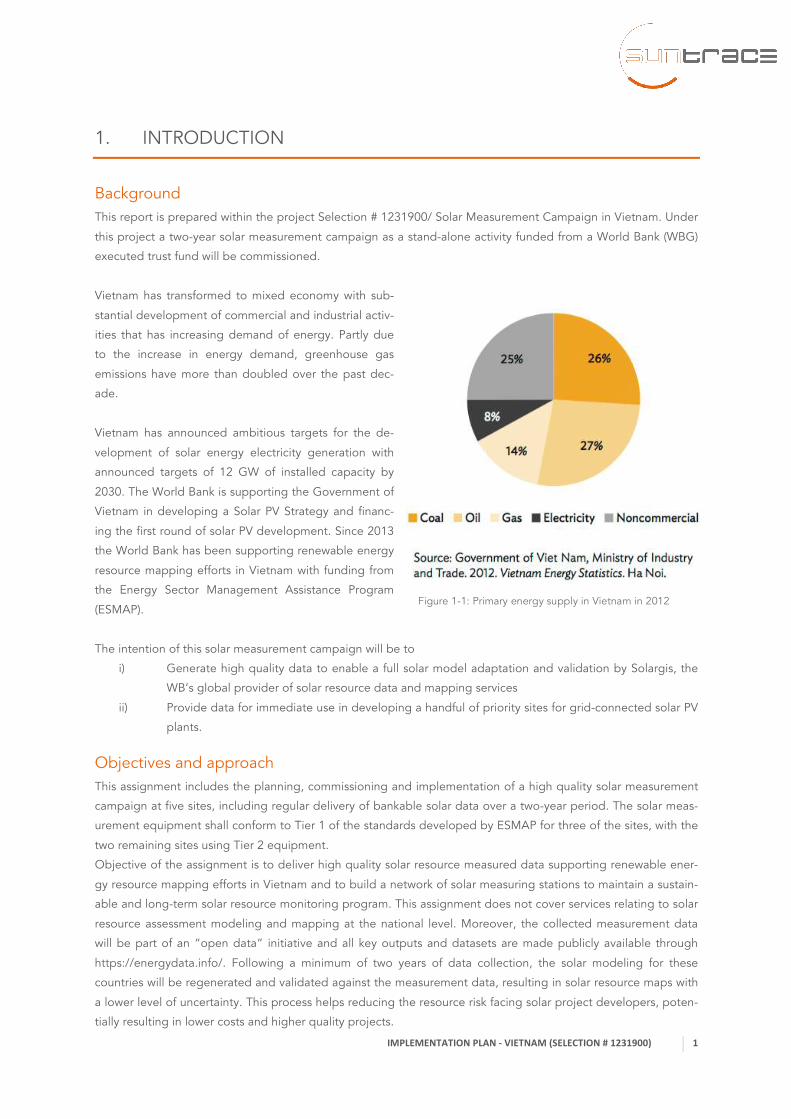
Vietnam has transformed to mixed economy with sub-
stantial development of commercial and industrial activ-
ities that has increasing demand of energy. Partly due
to the increase in energy demand, greenhouse gas
emissions have more than doubled over the past dec-
ade.
Vietnam has announced ambitious targets for the de-
velopment of solar energy electricity generation with
announced targets of 12 GW of installed capacity by
2030. The World Bank is supporting the Government of
Vietnam in developing a Solar PV Strategy and financ-
ing the first round of solar PV development. Since 2013
the World Bank has been supporting renewable energy
resource mapping efforts in Vietnam with funding from
the Energy Sector Management Assistance Program
(ESMAP).
The intention of this solar measurement campaign will be to
i) Generate high quality data to enable a full solar model adaptation and validation by Solargis, the
WB’s global provider of solar resource data and mapping services
ii) Provide data for immediate use in developing a handful of priority sites for grid-connected solar PV
plants.
Objectives and approach This assignment includes the planning, commissioning and implementation of a high quality solar measurement
campaign at five sites, including regular delivery of bankable solar data over a two-year period. The solar meas-
urement equipment shall conform to Tier 1 of the standards developed by ESMAP for three of the sites, with the
two remaining sites using Tier 2 equipment.
Objective of the assignment is to deliver high quality solar resource measured data supporting renewable ener-
gy resource mapping efforts in Vietnam and to build a network of solar measuring stations to maintain a sustain-
able and long-term solar resource monitoring program. This assignment does not cover services relating to solar
resource assessment modeling and mapping at the national level. Moreover, the collected measurement data
will be part of an “open data” initiative and all key outputs and datasets are made publicly available through
https://energydata.info/. Following a minimum of two years of data collection, the solar modeling for these
countries will be regenerated and validated against the measurement data, resulting in solar resource maps with
a lower level of uncertainty. This process helps reducing the resource risk facing solar project developers, poten-
tially resulting in lower costs and higher quality projects.
Figure 1-1: Primary energy supply in Vietnam in 2012

IMPLEMENTATION PLAN -‐ VIETNAM (SELECTION # 1231900)
2
This report provides information on the implementation of the two-year measurement campaign including:
• Introduction (This Chapter 1)
• The project consortium and roles of partners (Chapter 2)
• Solar measurement stations (Chapter 3)
• Tasks and deliverables (Chapter 4)
• Assessment of risks (Chapter 5)
• Permits and import procedure (Chapter 6)
This proposal for the Implementation of the ESMAP measurement campaign in Vietnam follows the methodolo-
gy and work plan initially described in the Technical Proposal. With this report it will be updated and further
elaborated.
The goal is to make all stations operational before end of July 2017 and hold an official inauguration in the end
of August or in September. The first annual site reports will be delivered after 12 complete months of measured
data and thoroughly checked in September 2018. The second annual site report is planned for delivery in Sep-
tember 2019 after finishing 24 complete months of measurements, and re-visiting the stations with an exchange
of the solar radiation sensors by refurbished and recalibrated instruments. The mandate will be then completed
with a wrap-up meeting and handing over the stations to a local organization for continued operation.
Technical Consultations This Implementation Plan is a result of consultations during the Inception Mission conducted from February 22nd
until March 3rd 2017 and the Site Selection Report, which was submitted to Word Bank on April 11th 2017.
The project was kicked-off on Monday February 22nd in the offices of World Bank in Hanoi in an informal meeting
with the respective WB team consisting of Technical Team Lead (TTL) Ky Hong Tran, Senior Energy Specialist of
the ESMAP Program Oliver Knight, and ESMAP Energy Specialist Martin Schroeder, who is in charge of the GIS-
based rooftop mapping project, which is covering Ho Chi Minh City (HCMC) and Da Nang. In this meeting the
principal objectives as given in the ToR had been confirmed. Instead of the site #4 in the South at Binh Thuan, it
was asked to select an alternate site as otherwise relatively many stations would be set up in the South of Vi-
etnam, while the Central regions of the country would only be measured at near Da Nang, which might not be
very representative. Further, the originally suggested site #4 at Binh Thuan would be situated relatively close to
the coast. Because measurement sites near the coast can have strong microclimatic influences and satellite pixels
partly covered by sea and land are known to cause problems in cloud detection and thus tend to be more erro-
neous than homogeneous pixels, the site Binh Thuan should be exchanged against another one. The Consult-
ants have been asked to propose alternate sites preferably in the Central Highlands, where it is known that also
large floating PV plants might be planned.
In a first meeting of the project partners, the Local Experts from Vatec (its CEO Bui Van Tien and Vice Manager
Power Eng. Nguyen Tan Tien) have been instructed by International Expert Dr. Richard Meyer CTO of Suntrace
GmbH on the general layout of solar measurement stations, its functions, the requirements for proper operations
and the criteria for selecting suitable locations for high quality solar measurements. The knowledge was immedi-
ately applied in an exercise for selecting suitable sites throughout the country following WB requests. At the first
site near Hanoi, based on the criteria for good viewing conditions, security and availability more than 5 potential
locations have been pre-selected using satellite-based maps.
In the course of the two-week-long Inception Mission the Local Experts and the International Expert from Sun-
trace visited all 6 sites considered to be suitable for erection of solar stations in Vietnam. At each site, several
potential locations have been pre-selected, where the stations likely could be erected. These Locations were
found in agreement with Experts considering the local needs for upcoming solar power projects. Finally, it was
evaluated at which three sites it would be best to chose the more demanding high quality TIER 1 stations. Sug-
gestions for erection of the more robust TIER 2 stations are mainly given where security of the stations was
IMPLEMENTATION PLAN -‐ VIETNAM (SELECTION # 1231900)
3
thought to be lower and maintenance might be more difficult to keep. The results of the site selection were
already summarized in the Site Selection Report delivered prior to this Implementation Report.
On the second day in Hanoi, the ESMAP solar measurement project was publicly announced at the Workshop on
global trends in solar PV prices; introduction to auctions; solar measurement campaign, held at the Ministry of
Industry and Trade (MOIT). In a meeting with EVN, the goals of the measurement campaign were explained in
more detail. A presentation of Senior Engineer Gin Bawn of ITPenergised pointed out the large potential which
floating PV might have in Vietnam. This motivated to erect some of the stations at sites near dams, where large
floating PV Plants might likely be realized. Such floating PV plants are expected to have higher CAPEX, which
might partly be outbalanced by higher productivity mainly due to cooler module temperatures expected over
water surfaces. To qualify sites for this relatively new sort of solar plants, it seems highly recommended to have
detailed assessments of local conditions. The potential yield should closely be checked which mainly requires
high quality solar radiation data. As higher corrosion and perhaps lower soiling rates near water bodies might
strongly affect financial key parameters, it is recommended to measure also these parameters.
IMPLEMENTATION PLAN -‐ VIETNAM (SELECTION # 1231900)
4
2. THE PROJECT CONSORTIUM AND ROLES OF PARTNERS
Suntrace is executing the measurement campaign in cooperation with its local partner company in Vietnam sup-
ported by hosts of the stations and their station keepers. Suntrace GmbH contributes its international expertise
in renewable energy project management in particular solar resource measurement expertise. It joins forces with
Vietnam Applied Technical Co. Ltd. (VATEC) in order to provide local expertise for this solar resource measure-
ments project. This Chapter describes the roles of the partners and distribution of works.
Partners and stakeholders involved
International Measurement Experts from Suntrace GmbH
Suntrace covers most relevant solar markets from its headquarter in Hamburg, and provides a reliable and prov-
en network of representative offices and cooperation partners. Suntrace’ senior management has strong back-
grounds in engineering, research and finance, including hands-on long-term management experience on power
projects during all stages from development until operation.
An international team of 16 staff and 10 free-lancers specialized in solar power can draw on several decades of
relevant advisory and management experience in international power in both renewable and conventional pow-
er. Combined team expertise exceeds 4 GW of power plants developed, financed, built and operating.
Suntrace’ Solar Resource Team is specialized in solar resource assessments and on site solar energy specific
measurements. Richard Meyer, who holds a doctorate in Physics of the Atmosphere with specialization on satel-
lite-derived radiation retrievals and measurements, leads the group. Richard’s team at Suntrace is composed of
one Project Manager, one Senior Engineer with more than 10 years experience in solar resources, two measure-
ment experts with more than 5 years of professional experience, one GIS expert, and three bachelors of meteor-
ology. Dr. Meyer and Dr. Lezaca together with Theresa Mieslinger and Marko Schwandt prepared a full university
lecture at Master Level on Solar Resource and Solar Measurements. They have held various training courses on
the topic of solar resource for industry, university and governmental institutions lasting from half day up to 8 full
days of training.
Over the past 7 years Suntrace has installed, operated and supervised solar measurement stations for industry,
research institutes, utilities and IPPs in more than 15 countries. Currently Suntrace is assigned for solar measure-
ments in Maldives, Bangladesh and Ethiopia for World Bank Group
For the WB ESMAP project on solar measurements in Vietnam Suntrace is the lead contractor. Suntrace is man-
aging the communication with World Bank, it sources and checks the required equipment, is responsible for
shipping the equipment to the country and will lead the installation and operation until hand over of the stations
to local stakeholders. For assuring high quality of the measured data Suntrace is remotely controlling the sta-
tions, and will generate monthly and annual reports and data files. To work efficiently Suntrace closely cooper-
ates with its local partner company, which is trained so that the Local Experts can handle as many actions on
their own as possible.
Local Partner: Vietnam Applied Technical Co. Ltd (VATEC)
For realizing the solar measurements in Vietnam Suntrace is subcontracting VATEC. With three offices in Vi-
etnam, one in Nha Trang City, one in Da Nang City and another in Ho Chi Minh City, VATEC is perfectly situated
for offering logistical services for all sites chosen for the present assignment.
Vietnam Applied Technical Co. Ltd (VATEC), Vietnam, was established in 2011. VATEC provides investment and
engineering consulting services (Owner’s, Lender’s and Contractor’s Engineer) for renewable energy projects as
IMPLEMENTATION PLAN -‐ VIETNAM (SELECTION # 1231900)
5
well as ensures technical solution, equipment supply and after sales services for solar power installations. VATEC
is also working in the renewable energy development in Vietnam with project development and international
cooperation. VATEC employs 40 employees in its consultancy business of which 20 are engineers. 15 additional
employees belong to the solar power EPC department.
Project Stakeholders
The main stakeholder in this project is the state-owned utility Electricity Vietnam (EVN). Although the power
sector in Vietnam will be more and more deregulated, and allows now Independent Power Producers (IPP) to
contribute to the fast growing electricity demand. EVN is expected to remain the most important power produc-
er in all parts of the country. EVN and its regional bodies called CPC, are open for solar energy projects. Most
staff of EVN encountered during the Inception Mission was highly interested in solar energy applications. E.g.
Director Mr. Van Thien Nhan of the EVN Hydro Power Company (HPC) located in Dak Lak Province in the Central
Highlands, already operated a small solar demo, where he logs the performance of some PV panels set up on
the powerhouse of one of his hydro plants. He expressed the clear intention to erect a floating PV demo plant of
around 20 MW size as soon as possible.
Several PV plant intentions of private developers have been announced. As World Bank currently sees the best
chances for larger PV projects to be financed with EVN, most of the sites should be located at EVN sites. This has
also the advantage that stations at Locations under control of EVN are well guarded and likely can be sustained
beyond the initial 24 months of measurements, which are funded by WB’s ESMAP program. In general it was
found that the technical skills of EVN staff are high and motivation is good. Thus, it is wise to concentrate on
EVN and its subsidiaries as hosts for the solar stations.
IMPLEMENTATION PLAN -‐ VIETNAM (SELECTION # 1231900)
6
3. SOLAR MEASUREMENT STATIONS
Final selection of sites The selection of sites is the result of the Inception mission from 22.02.2017 until 02.03.2017 where Suntrace
visited and identified most suitable hosts and sites. As a result, 5 sites were selected and three Tier 1 will be
installed at the EVN sites and 2 Tier 2 stations at private rooftops. The sites that are selected are based on the
preliminary Site Selection Report, elaborated by the consultant and in agreement with the provider of the final
solar resource mapping supplier, who pre-selected and proposed suitable regions.
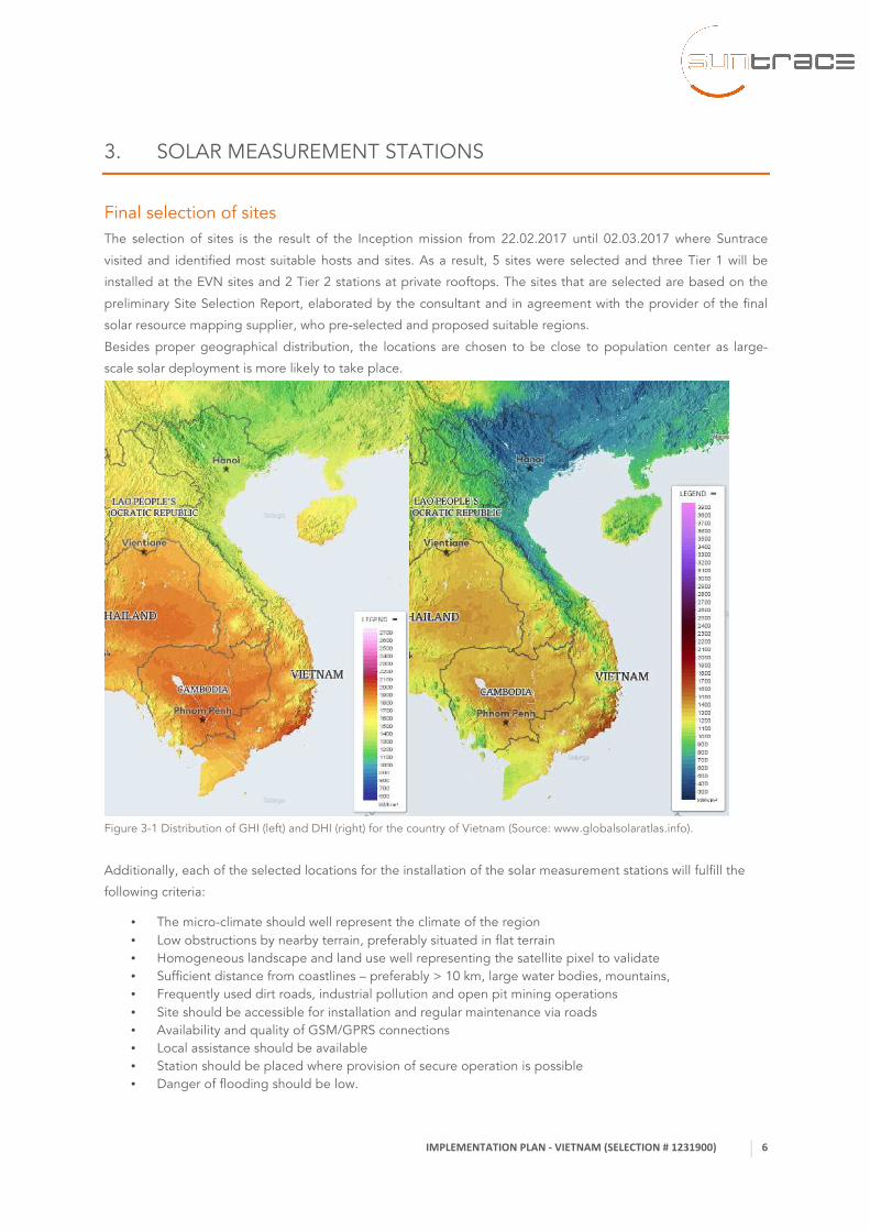
Besides proper geographical distribution, the locations are chosen to be close to population center as large-
scale solar deployment is more likely to take place.
Figure 3-1 Distribution of GHI (left) and DHI (right) for the country of Vietnam (Source: www.globalsolaratlas.info).
Additionally, each of the selected locations for the installation of the solar measurement stations will fulfill the
following criteria:
• The micro-climate should well represent the climate of the region • Low obstructions by nearby terrain, preferably situated in flat terrain • Homogeneous landscape and land use well representing the satellite pixel to validate • Sufficient distance from coastlines – preferably > 10 km, large water bodies, mountains, • Frequently used dirt roads, industrial pollution and open pit mining operations • Site should be accessible for installation and regular maintenance via roads • Availability and quality of GSM/GPRS connections • Local assistance should be available • Station should be placed where provision of secure operation is possible • Danger of flooding should be low.

IMPLEMENTATION PLAN -‐ VIETNAM (SELECTION # 1231900)
7
Table 3-1 shows the 5 selected locations for solar measurement stations in the ESMAP program in Vietnam. At 3
sites Tier 1 stations will be installed, which provide the highest possible accuracy for operational solar measure-
ment stations. At 2 additional sites stations of Tier 2 quality shall be erected. As the Tier 2 stations are not
equipped with a very soiling-sensitive pyrheliometer, but use a Rotating Shadowband Irradiometer (RSI) to derive
DNI, the Tier 2 stations are erected at those places where utmost quality is not needed or no daily cleaning is
expected to be assured.
Site name and description Type Site code Elevation Latitude Longitude Hanoi region: Bac Ninh on rooftop of new
EVN bldg.
Tier1 VNHAN 40 m 21.2015°N 106.0630°E
Da Nang on rooftop of EVN/CPC bldg.
within the city
Tier2 VNDAN 20 m 16.01257°N 107.18649°E
Central Highlands region on ground be-
fore EVN bldg. near hydro spillway
Tier1 VNCEH 275 m 12.7534°N 107.8763°E
Song Binh station location on private
house rooftop
Tier2 VNSOB 59 m 11.2640°N 108.3452°E
Tri An region near HCMC on top of EVN
bldg. near water spillway
Tier1 VNTRA 57 m 11.1024°N 107.0378°E
Table 3-1. Selected sites for solar measurement stations in Vietnam within the WB ESMPÀP program.
Figure 3-2 Country map showing promising sites for solar measurement stations currently considered for the Vietnam ESMAP
project.
IMPLEMENTATION PLAN -‐ VIETNAM (SELECTION # 1231900)
8
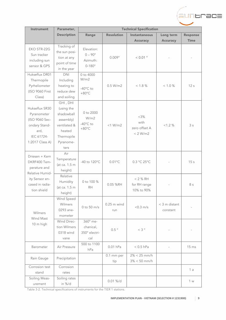
Solar and meteorological measurement equipment The instrumentation of the 3 Tier 1 stations to be erected will be as described in Table 3-2. The key instruments
are a one pyrheliometer and one shaded and one unshaded pyranometer, which will all be mounted on a solar
tracker. The quality of this instrumentation for a Tier 1 station fulfills BSRN requirements as outlined by the BSRN
Archive (see http://epic.awi.de/44345/1/BSRN_StationRequirements_Status20170401.pdf). To comply well with
these specifications, ventilation and heating of the pyranometers is strongly recommended by BSRN. Especially
this is the case in hot and humid environments, like those sites in Vietnam, where the ESMAP stations shall be
erected. Therefore, it was decided to opt for pyranometers, which are equipped with ventilation. Thus, the pyra-
nometers of these Tier 1 stations comply with the new IEC standard (IEC 61724-1:2017), which requires ventilat-
ed and heated pyranometers to fulfill its highest quality level Class A.
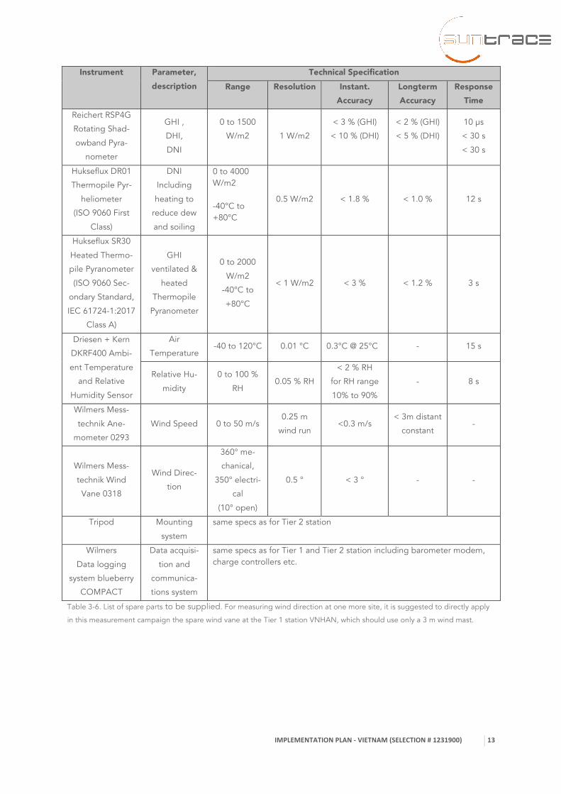
The two Tier 2 stations are equipped as given in Table 3-4 and Table 3-5. The Tier 2 stations are designed to be
very robust and less sensitive to cleaning, as DHI and DNI will be measured by a Rotating Shadowband Irradi-
ometer (RSI). The Reichert RSP4G, which will be installed here, is known to be a precise and robust instrument.
Contrary to pyrheliometers, which are used in Tier 1 stations and require daily cleaning to reach its outstanding
accuracy, it is sufficient to clean such RSI only weekly. In order to reach high quality , the Tier 2 stations will also
be equipped with a thermopile pyranometer, which complies with Secondary Standard requirements, (highest
quality Level of ISO 9060 (1990)). Here we apply the Hukseflux SR20, which is equipped with dome heating to
reduce the influence of dew, but is not ventilated. This pyranometer will be used for improving the calibration of
the RSI by applying an in-situ calibration.
All auxiliary parameters will be measured with the same quality instruments as for the Tier 1 station. A major
difference is that instead of the WMO standard height of 10 m only a 3 m wind mast will be used and this is only
equipped with an anemometer for measuring wind speed, but missing a wind vane for also reporting wind direc-
tions.
Most of the locations selected here will be situated on rooftops. If the building is of a height far below 10 m, it is
recommended for wind measurements at 10 m levels to adjust the height of the mast in such way that the wind
sensors are placed at a height of 10 m above ground. The 10 m mast delivered with the Tier 1 stations is freely
adjustable from a minimum height of 3 m to 10 m.
As 10 m wind values are also strongly recommended for Tier 2 sites, we suggest exchanging the 10 m wind mast
from the high building at Location VNHAN against a 3 m mast, which is sufficient for wind measurements on
such a high building. The 10 m wind mast from the VNHAN station shall be relocated to the low rooftop of
VNSOB, to adjust the measurements there to the 10 m standard height. For compliance with the Tier 1 station
requirement of having also wind direction available, in this case we will activate the wind direction sensor from
the Spare Parts and install the wind vane on the 3 m mast at VNHAN.
IMPLEMENTATION PLAN -‐ VIETNAM (SELECTION # 1231900)
9
Instrument Parameter, Description
Technical Specification Range Resolution Instantaneous
Accuracy Long term Accuracy
Response Time
EKO STR-22G
Sun tracker
including sun
sensor & GPS
Tracking of
the sun posi-
tion at any
point of time
in the year
Elevation:
0 – 90°
Azimuth:
0-180°
0.009° < 0.01 ° - -
Hukseflux DR01
Thermopile
Pyrheliometer
(ISO 9060 First
Class)
DNI
Including
heating to
reduce dew
and soiling
0 to 4000 W/m2
-40°C to +80°C
0.5 W/m2 < 1.8 % < 1.0 % 12 s
Hukseflux SR30
Pyranometer
(ISO 9060 Sec-
ondary Stand-
ard,
IEC 61724-
1:2017 Class A)
GHI , DHI
(using the
shadowball
assembly)
ventilated &
heated
Thermopile
Pyranome-
ters
0 to 2000
W/m2
-40°C to +80°C
<1 W/m2
<3%
with
zero offset A
< 2 W/m2
<1.2 % 3 s
Driesen + Kern
DKRF400 Tem-
perature and
Relative Humid-
ity Sensor en-
cased in radia-
tion shield
Air
Temperature
(at ca. 1.5 m
height)
-40 to 120°C 0.01°C 0.3 °C 25°C - 15 s
Relative
Humidity
(at ca. 1.5 m
height)
0 to 100 %
RH 0.05 %RH
< 2 % RH
for RH range
10% to 90%
- 8 s
Wilmers
Wind Mast
10 m high
Wind Speed
Wilmers
0293 ane-
mometer
0 to 50 m/s 0.25 m wind
run <0.3 m/s
< 3 m distant
constant -
Wind Direc-
tion Wilmers
0318 wind
vane
360° me-
chanical,
350° electri-
cal
0.5 ° < 3 ° - -
Barometer Air Pressure 500 to 1100
hPa 0.01 hPa < 0.5 hPa - 15 ms
Rain Gauge Precipitation 0.1 mm per
tip
2% < 25 mm/h
3% < 50 mm/h
Corrosion test
stand
Corrosion
rates 1 a
Soiling Meas-
urement
Soiling rates
in %/d 0.01 %/d 1 w
Table 3-2. Technical specifications of instruments for the TIER 1 stations.

IMPLEMENTATION PLAN -‐ VIETNAM (SELECTION # 1231900)
10
Equipment Use Characteristics Weather proof
control cabinet
Protection • IP65 protection marking
Wilmers
Data logging
system blueberry
COMPACT
Data acquisition and
communications system
• full built-in Linux system for signal processing and instrumenta-tion control
• GPRS/GSM modem for data transmission and remote configu-ration
• charge controllers for battery use • digital and analog measurement inputs • Serial RS485, RS232 and Ethernet interfaces • Modbus RTU and Modbus TCP for SCADA systems connection
PV panel Off grid Power • 1 x 250 Wp
Redundant Bat-
teries Power back-up • 2 x 12V 15 Ah for basic operation of Data Logger
• 2 x 12V 100 Ah • sealed lead batteries • Allows at least 3 days of autonomy, if power supply is lost
Lightning
protection kit Protection • grounding cable for solar station / data logger
• 2nd grounding cable for wind mast connected to a single point low resistance copper or aluminum rod connected to low re-sistance grounding point.
• multi-level overvoltage protection is standard in the supplied data logging system
Mounting
material
Structure • mounting structures for installation of all supplied instruments • 10 m wind mast • cabling following best practices
Table 3-3. Operation equipment for the TIER 1 stations.

IMPLEMENTATION PLAN -‐ VIETNAM (SELECTION # 1231900)
11
Instrument Parameter, description
Technical Specification Range Resolution Instantaneous
Accuracy Long term Accuracy
Response Time
Reichert
RSP4G Rotat-
ing Shadow-
band Pyra-
nometer
GHI ,
DHI,
DNI
0 to 1500
W/m2
1 W/m2
< 3 % (GHI)
< 10 % (DHI)
< 2 % (GHI)
< 5 % (DHI)
10 μs
< 30 s
< 30 s
Hukseflux
SR20 Pyra-
nometer (ISO
9060 Second-
ary Standard)
GHI
heated Ther-
mopile Pyra-
nometer
0 to 2000
W/m2
-40°C to
+80°C
< 1 W/m2 < 3 % < 1.2 % 3 s
Driesen +
Kern
DKRF400
Temperature
and Relative
Humidity
Sensor en-
cased in radia-
tion shield
Air
Temperature
(at ca. 1.5 m
height)
-40 to 120°C 0.01 °C 0.3°C @25°C - 15 s
Relative Hu-
midity
(at ca. 1.5 m
height)
0 to 100 %
RH 0.05 %RH
< 2 % RH
for RH range
10% to 90%
- 8 s
Wilmers Wind
Mast 3 m
height
Wind Speed
(at 3 m) 0 to 50 m/s
0.25 m wind
run <0.3 m/s
< 3 m distant
constant -
Barometer
Air Pressure
(at ca. 1.5 m
height)
500 to 1100
hPa 0.01 hPa < 0.5 hPa - 15 ms
Rain Gauge Precipitation 0.1 mm per
tip
2% < 25 mm/h
3% < 50 mm/h 60 s
Corrosion test
stand
Corrosion
rates 1 a
Soiling Meas-
urement
Soiling rates
in %/d 0.01 %/d 1 w
Table 3-4. Technical specifications of instruments for the TIER 2 stations.

IMPLEMENTATION PLAN -‐ VIETNAM (SELECTION # 1231900)
12
Equipment Use Characteristics Weather proof
control cabinet
Protection • IP65 protection marking
Wilmers
Data logging
system
blueberry COM-
PACT
Data acquisition and
communications system
• full built-in Linux system for signal processing and instrumenta-tion control
• GPRS/GSM modem for data transmission and remote configu-ration
• charge controllers for battery use • digital and analog measurement inputs • Serial RS485, RS232 and Ethernet interfaces • Modbus RTU and Modbus TCP for Scada systems connection
PV panel Off grid Power • 1 x 12 V 60 Wp
Redundant Bat-
teries Power back-up • 2 x 12 V 15 Ah
• sealed lead battery • Allows 1 week of autonomy in the case where constant bad
weather persists for a prolonged period of time.
Lightning
protection kit Protection • grounding cable for solar station / data logger
• 2nd grounding cable for wind mast connected to a single point low resistance copper or aluminum rod connected to low re-sistance grounding point.
• multi-level overvoltage protection in data logger Tripod Mounting system • Robust tripod made of aluminum
• Feet may be set up on bare soil, or flat surfaces like con-crete, fixed typically anchored by screws
• Height adjustable, so that RSP, pyranometers are at approx.. 2 m height
Mounting
material
Structure • mounting structures for installation of all instruments • cabling following best practices
Table 3-5. Operation equipment for the TIER 2 stations.
IMPLEMENTATION PLAN -‐ VIETNAM (SELECTION # 1231900)
13
Instrument Parameter, description
Technical Specification Range Resolution Instant.
Accuracy Longterm Accuracy
Response Time
Reichert RSP4G
Rotating Shad-
owband Pyra-
nometer
GHI ,
DHI,
DNI
0 to 1500
W/m2
1 W/m2
< 3 % (GHI)
< 10 % (DHI)
< 2 % (GHI)
< 5 % (DHI)
10 μs
< 30 s
< 30 s
Hukseflux DR01
Thermopile Pyr-
heliometer
(ISO 9060 First
Class)
DNI
Including
heating to
reduce dew
and soiling
0 to 4000 W/m2
-40°C to +80°C
0.5 W/m2 < 1.8 % < 1.0 % 12 s
Hukseflux SR30
Heated Thermo-
pile Pyranometer
(ISO 9060 Sec-
ondary Standard,
IEC 61724-1:2017
Class A)
GHI
ventilated &
heated
Thermopile
Pyranometer
0 to 2000
W/m2
-40°C to
+80°C
< 1 W/m2 < 3 % < 1.2 % 3 s
Driesen + Kern
DKRF400 Ambi-
ent Temperature
and Relative
Humidity Sensor
Air
Temperature -40 to 120°C 0.01 °C 0.3°C @ 25°C - 15 s
Relative Hu-
midity
0 to 100 %
RH 0.05 % RH
< 2 % RH
for RH range
10% to 90%
- 8 s
Wilmers Mess-
technik Ane-
mometer 0293
Wind Speed 0 to 50 m/s 0.25 m
wind run <0.3 m/s
< 3m distant
constant -
Wilmers Mess-
technik Wind
Vane 0318
Wind Direc-
tion
360° me-
chanical,
350° electri-
cal
(10° open)
0.5 ° < 3 ° - -
Tripod Mounting
system
same specs as for Tier 2 station
Wilmers
Data logging
system blueberry
COMPACT
Data acquisi-
tion and
communica-
tions system
same specs as for Tier 1 and Tier 2 station including barometer modem, charge controllers etc.
Table 3-6. List of spare parts to be supplied. For measuring wind direction at one more site, it is suggested to directly apply
in this measurement campaign the spare wind vane at the Tier 1 station VNHAN, which should use only a 3 m wind mast.
IMPLEMENTATION PLAN -‐ VIETNAM (SELECTION # 1231900)
14
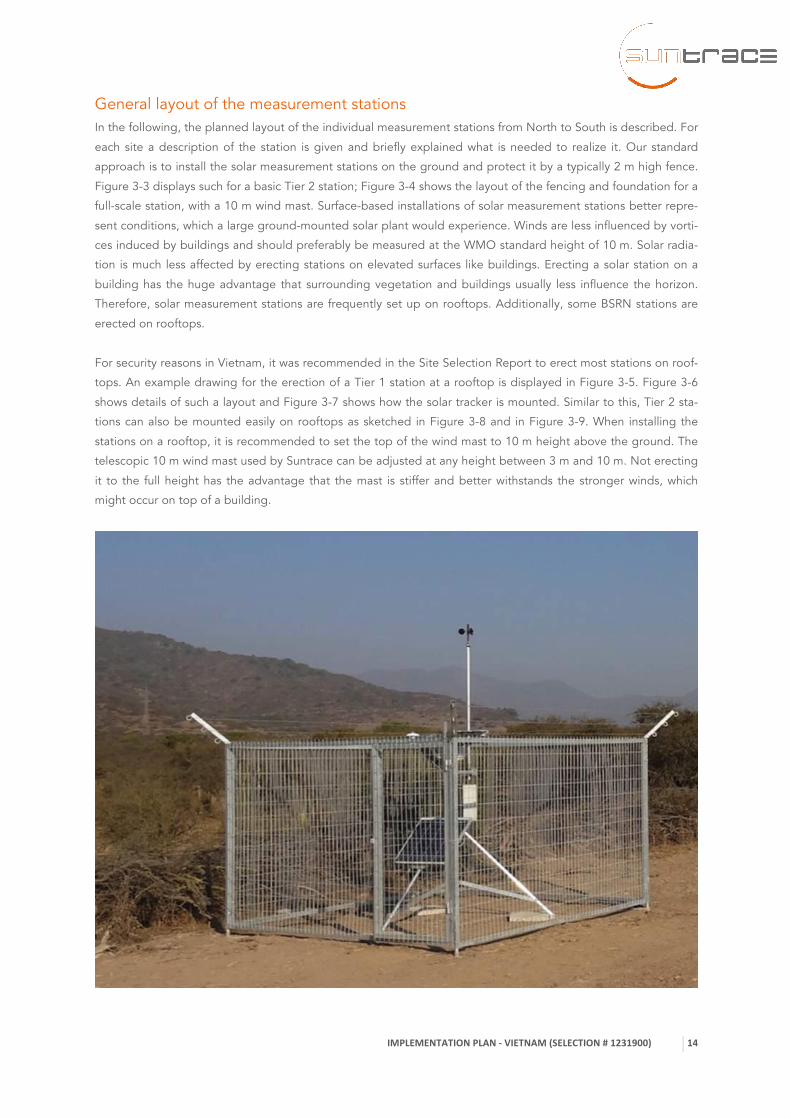
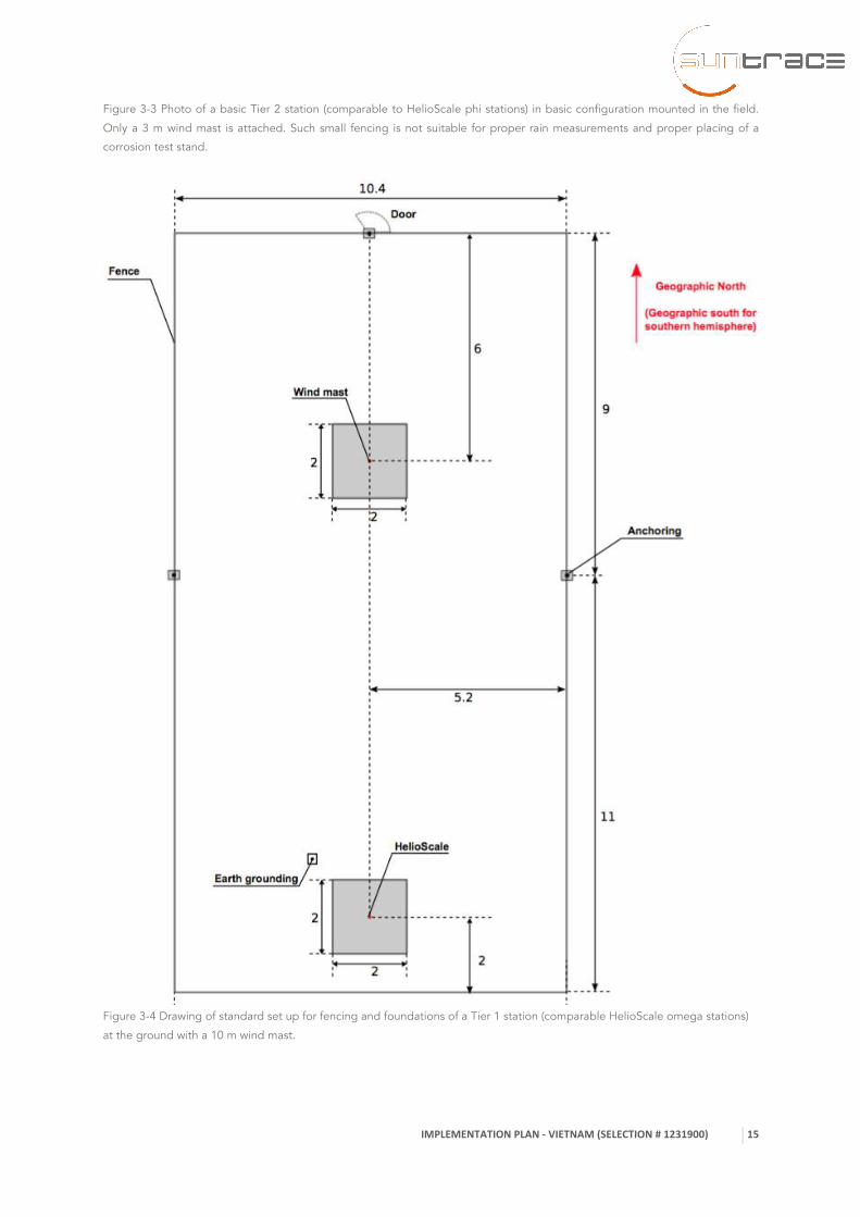
General layout of the measurement stations In the following, the planned layout of the individual measurement stations from North to South is described. For
each site a description of the station is given and briefly explained what is needed to realize it. Our standard
approach is to install the solar measurement stations on the ground and protect it by a typically 2 m high fence.
Figure 3-3 displays such for a basic Tier 2 station; Figure 3-4 shows the layout of the fencing and foundation for a
full-scale station, with a 10 m wind mast. Surface-based installations of solar measurement stations better repre-
sent conditions, which a large ground-mounted solar plant would experience. Winds are less influenced by vorti-
ces induced by buildings and should preferably be measured at the WMO standard height of 10 m. Solar radia-
tion is much less affected by erecting stations on elevated surfaces like buildings. Erecting a solar station on a
building has the huge advantage that surrounding vegetation and buildings usually less influence the horizon.
Therefore, solar measurement stations are frequently set up on rooftops. Additionally, some BSRN stations are
erected on rooftops.
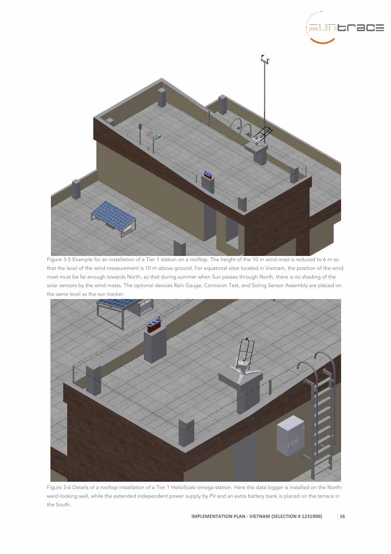
For security reasons in Vietnam, it was recommended in the Site Selection Report to erect most stations on roof-
tops. An example drawing for the erection of a Tier 1 station at a rooftop is displayed in Figure 3-5. Figure 3-6
shows details of such a layout and Figure 3-7 shows how the solar tracker is mounted. Similar to this, Tier 2 sta-
tions can also be mounted easily on rooftops as sketched in Figure 3-8 and in Figure 3-9. When installing the
stations on a rooftop, it is recommended to set the top of the wind mast to 10 m height above the ground. The
telescopic 10 m wind mast used by Suntrace can be adjusted at any height between 3 m and 10 m. Not erecting
it to the full height has the advantage that the mast is stiffer and better withstands the stronger winds, which
might occur on top of a building.
IMPLEMENTATION PLAN -‐ VIETNAM (SELECTION # 1231900)
15
Figure 3-3 Photo of a basic Tier 2 station (comparable to HelioScale phi stations) in basic configuration mounted in the field.
Only a 3 m wind mast is attached. Such small fencing is not suitable for proper rain measurements and proper placing of a
corrosion test stand.
Figure 3-4 Drawing of standard set up for fencing and foundations of a Tier 1 station (comparable HelioScale omega stations)
at the ground with a 10 m wind mast.
IMPLEMENTATION PLAN -‐ VIETNAM (SELECTION # 1231900)
16
Figure 3-5 Example for an installation of a Tier 1 station on a rooftop. The height of the 10 m wind mast is reduced to 6 m so
that the level of the wind measurement is 10 m above ground. For equatorial sites located in Vietnam, the position of the wind
mast must be far enough towards North, so that during summer when Sun passes through North, there is no shading of the
solar sensors by the wind masts. The optional devices Rain Gauge, Corrosion Test, and Soling Sensor Assembly are placed on
the same level as the sun tracker.
Figure 3-6 Details of a rooftop installation of a Tier 1 HelioScale omega station. Here the data logger is installed on the North-
ward-looking wall, while the extended independent power supply by PV and an extra battery bank is placed on the terrace in
the South.
IMPLEMENTATION PLAN -‐ VIETNAM (SELECTION # 1231900)
17
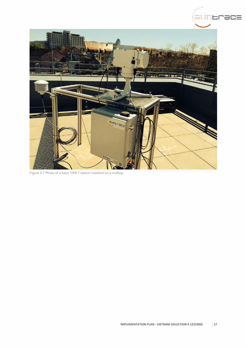
Figure 3-7 Photo of a basic TIER 1 station installed on a rooftop.

IMPLEMENTATION PLAN -‐ VIETNAM (SELECTION # 1231900)
18
Figure 3-8 Example for an installation of a Tier 2 station at a rooftop including a 10 m telescopic wind mast with height re-
duced to 6 m so that overall height above ground is 10 m.
Figure 3-9 Example for the core of a Tier 2 HelioScale phi station installed at a rooftop. The data logger may be mounted on
the North-facing wall, or alternatively to the tripod, where the RSP and the thermal pyranometer are mounted on the vertical
pipe together with the soiling assembly on the right.
Description of solar measurement sites Actual station layout needs to consider the local conditions found at each of the sites. For the 5 solar measure-
ment stations to be erected in Vietnam the following layouts are foreseen:

IMPLEMENTATION PLAN -‐ VIETNAM (SELECTION # 1231900)
19
2.1 Bac Ninh near Hanoi - VNHAN
Site description Site code Elevation Latitude Longitude Bac Ninh – new EVN building VNHAN 40 m 21.2015°N 106.0630°E
Figure 3-10: Location of VNHAN relative to the extent of the region
Description of site:
• This site was selected for hosting a TIER 1 station
• The site is located in the small city of Bac Ninh of the capital of Bac Ninh Province. Located about 30
km Northeast from Hanoi with about 45 min car travel to the Hanoi international airport.
• Larger PV rooftop installations are expected to be built in the area. Thus, measurements in this region
are not only well representative, but can also have practical value to allow easier financing if this site will
be measured well.
• The rooftop provided by EVN is on a relatively high building at about 35 m. Advantages are that local
staff is highly motivated to support the operations and horizon there is perfectly flat.
Figure 3-11: Rooftop new building of EVN with fully flat horizon (VNHAN)

IMPLEMENTATION PLAN -‐ VIETNAM (SELECTION # 1231900)
20
Figure 3-12: Sun path at the site VNHAN
The Tier 1 station near Hanoi VNHAN will be erected on the rooftop of the local head office of EVN. The rooftop
has two terraces. The larger lower laying terrace will be avoided as it is largely occupied by air conditioning
equipment. This will cause some horizon obstruction and it will partly influence measurements of ambient air and
thus has to be avoided.
The uppermost rooftop terrace is still more than large enough for erection of all solar and auxiliary equipment
recommended. It would even allow to set up several stations to run them in parallel for a cross comparison.
For the permanent installation of a Tier 1 station, its Sun Tracker should be installed towards the Southern part of
the upper terrace. It should be positioned in about 2 m distant from the roof’s edge so that it can be well ac-
cessed for daily cleaning and other maintenance measures. The auxiliary measurements should be set up nearby,
but distant enough to avoid any reflections or shading of the radiometers. As the building height is already ex-
ceeding 10 m in this case we only use a 3 m wind mast. The 10 m wind mast freed here shall be used at the Tier
2 site VNSOB, which will be installed on a much lower roof. To comply with the Tier 1 requirement of having a
wind direction sensor, the spare wind vane shall be directly installed.
As additional equipment beyond the standard Tier 1, only a soiling measurement assembly (with 3 PV Reference
Cells incl. IEC 17025 calibration cabling, data logger upgrade) shall be erected at this station.
IMPLEMENTATION PLAN -‐ VIETNAM (SELECTION # 1231900)
21
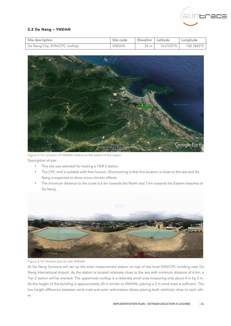
2.2 Da Nang – VNDAN
Site description Site code Elevation Latitude Longitude Da Nang City, EVN/CPC rooftop VNDAN 24 m 16.0125°N 108.1865°E
Figure 3-13: Location of VNDAN relative to the extent of the region
Description of site:
• This site was selected for hosting a TIER 2 station
• The CPC roof is suitable with free horizon. Shortcoming is that this location is close to the sea and Da
Nang is expected to show micro-climatic effects.
• The minimum distance to the coast is 6 km towards the North and 7 km towards the Eastern beaches of
Da Nang.
Figure 3-14: Horizon plot for site VNDAN
At Da Nang Suntrace will set up the solar measurement station on top of the local EVN/CPC building near Da
Nang International Airport. As the station is located relatively close to the sea with minimum distance of 6 km, a
Tier 2 station will be erected. The uppermost rooftop is a relatively small area measuring only about 4 m by 5 m.
As the height of this building is approximately 20 m similar to VNHAN, placing a 3 m wind mast is sufficient. The
low height difference between wind mast and solar radiometers allows placing both relatively close to each oth-
er.

IMPLEMENTATION PLAN -‐ VIETNAM (SELECTION # 1231900)
22
For the installation at this site the following additional measures will be taken:
• Fixed ladder of approximately 3 m height to be mounted on Northern wall so that the rooftop can be
easily climbed
• Fence of 90 cm for safety surrounding the upper terrace
• Connection of the wind mast and the tripod to the existing lightning protection of the building.
• As additional equipment a soiling measurement assembly (with 3 PV Reference Cells) incl. IEC 17025
calibration cabling, data logger upgrade) is selected.
Figure 3-15:Sun path for VNDAN
IMPLEMENTATION PLAN -‐ VIETNAM (SELECTION # 1231900)
23
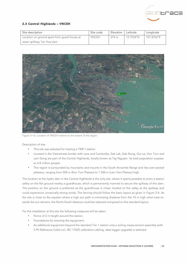
2.3 Central Highlands – VNCEH
Site description Site code Elevation Latitude Longitude Location on ground apart from guard house at
water spillway Tan Hoa dam
VNCEH 274 m 12.7534°N 107.8762°E
Figure 3-16: Location of VNCEH relative to the extent of the region
Description of site:
• This site was selected for hosting a TIER 1 station
• Located in the Vietnamese border with Laos and Cambodia, Dak Lak, Dak Nong, Gia Lai, Kon Tum and
Lam Dong are part of the Central Highlands, locally known as Tay Nguyen. Its total population surpass-
es 4.8 million people.
• The region is surrounded by mountains and mounts in the South Annamite Range and lies over several
plateaus, ranging from 500 m (Kon Tum Plateau) to 1 500 m (Lam Vien Plateau) high.
The location at the hydro dam in the Central Highlands is the only site, where it seems possible to erect a station
safely on the flat ground nearby a guardhouse, which is permanently manned to secure the spillway of this dam.
The position on the ground is preferred as the guardhouse is closer located to the valley at the spillway and
could experience unnaturally strong winds. The fencing should follow the basic layout as given in Figure 3-4. As
the site is close to the equator where a high sun path is minimizing shadows from the 10 m high wind mast to-
wards the sun sensors, the North-South distance could be reduced compared to this standard layout.
For the installation at this site the following measures will be taken:
• Fence of 2 m height around the station.
• Foundations for erecting the equipment.
• As additional equipment beyond the standard Tier 1 station only.a soiling measurement assembly (with
3 PV Reference Cells) incl. IEC 17025 calibration cabling, data logger upgrade) is selected.
IMPLEMENTATION PLAN -‐ VIETNAM (SELECTION # 1231900)
24
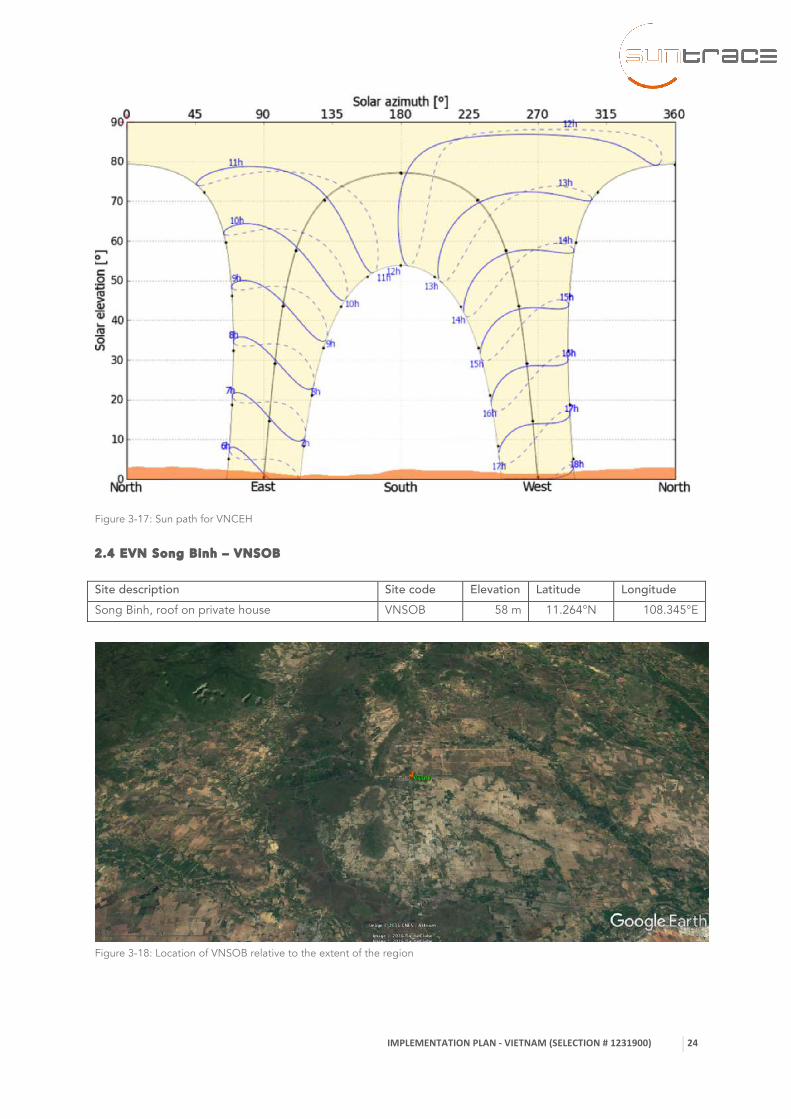
Figure 3-17: Sun path for VNCEH
2.4 EVN Song Binh – VNSOB
Site description Site code Elevation Latitude Longitude Song Binh, roof on private house VNSOB 58 m 11.264°N 108.345°E
Figure 3-18: Location of VNSOB relative to the extent of the region

IMPLEMENTATION PLAN -‐ VIETNAM (SELECTION # 1231900)
25
Description of site:
• This site was selected for hosting a TIER 2 station
• VNSOB is located on a private rooftop and shows the only suitable safe site.
• Trees are so distant that they hardly influence solar radiation measurements.
Figure 3-19: Horizon plot for VNSOB
Figure 3-20: Sun path for VNSOB
The site VNSOB near Song Binh is a good location to gather an additional point for improving the solar mapping
and supporting development of a larger PV plant by EVN subsidiaries nearby. As there could not be found any
public building or building of EVN, where a solar measurement station could be well operated, it was decided to
erect the station on top of a private house in the nearby village. The selected rooftop is solid and should easily
allow for erection of a Tier 2 station. As the building itself has a height of around 4 m, it is recommended to
extract the wind mast to a height of 6 m to reach a total height of 10 m above ground for the wind measure-
ments.
For the installation at this site the following additional measures will be taken:
• Fixed ladder of approximately 4 m height to be mounted on Western wall so that the rooftop can be
easily climbed from ground by the installation team and regularly by the house owner and the station
keeper.

IMPLEMENTATION PLAN -‐ VIETNAM (SELECTION # 1231900)
26
• Climbing protection for locking the ladder to avoid free access for everyone from the ground.
• No existing lightning protection of the building, so the wind mast will be grounded. Preferably, the
grounding cable should go towards West and be put besides the ladder reaching the ground in the
West of the house.
• Slight obstruction by trees in the West which are not regarded as severe, as it remains below 10° eleva-
tion angle and should be sufficient for a Tier 2 station. The effected minutes shortly before sunset could
be masked in the data to avoid bias when comparing with satellite-derived solar radiation data.
• As additional equipment, a soiling measurement assembly (with 3 PV Reference Cells incl. IEC 17025
calibration cabling, data logger upgrade) will be installed. At this station also a rain gauge is selected as
additional item by World Bank for measuring precipitation. A corrosion test stand shall be installed
here, which shall be exposed for 1 year, and then scientifically analyzed.
2.5 EVN Tri An dam – VNTRA
Site description Site code Elevation Latitude Longitude Tri An dam near water spillway on top of EVN
Bldg., where geotechnical bore cores are stored
VNTR3 58 m 11.1024°N 107.0378°E
Figure 3-21: : Location of VNTRA relative to the extent of the region
Description of site:
• This site was selected for hosting a TIER 1 station
• Tri An is a hydroelectric dam on the Dong Nai River, which has approximately 586 km in length and is
located in the rural district Vinh Cuu, part of the Dong Nai province.
• This location is close to the Tri An dam near water spillway on top of EVN building, where geotechnical
bore cores are stored.
IMPLEMENTATION PLAN -‐ VIETNAM (SELECTION # 1231900)
27
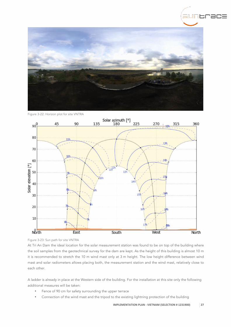
Figure 3-22: Horizon plot for site VNTRA
Figure 3-23: Sun path for site VNTRA
At Tri An Dam the ideal location for the solar measurement station was found to be on top of the building where
the soil samples from the geotechnical survey for the dam are kept. As the height of this building is almost 10 m
it is recommended to stretch the 10 m wind mast only at 3 m height. The low height difference between wind
mast and solar radiometers allows placing both, the measurement station and the wind mast, relatively close to
each other.
A ladder is already in place at the Western side of the building. For the installation at this site only the following
additional measures will be taken:
• Fence of 90 cm for safety surrounding the upper terrace
• Connection of the wind mast and the tripod to the existing lightning protection of the building

IMPLEMENTATION PLAN -‐ VIETNAM (SELECTION # 1231900)
28
• As additional equipment, a soiling measurement assembly (with 3 PV Reference Cells incl. IEC 17025
calibration cabling, data logger upgrade) shall be set up. Additionally, another corrosion test stand shall
be installed. This includes 1 year of exposure, and scientific analysis after 1 year of exposure.
IMPLEMENTATION PLAN -‐ VIETNAM (SELECTION # 1231900)
29
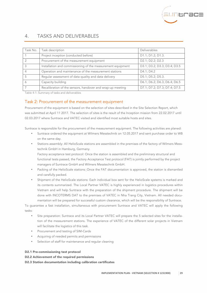
4. TASKS AND DELIVERABLES
Task No. Task description Deliverables
1 Project inception (conducted before) D1.1; D1.2; D1.3.
2 Procurement of the measurement equipment D2.1; D2.2; D2.3
3 Installation and commissioning of the measurement equipment D3.1; D3.2; D3.3; D3.4; D3.5
4 Operation and maintenance of the measurement stations D4.1; D4.2
5 Regular assessment of data quality and data delivery D5.1; D5.2; D5.3.
6 Capacity building D6.1; D6.2; D6.3; D6.4; D6.5
7 Recalibration of the sensors, handover and wrap-up meeting D7.1; D7.2; D7.3; D7.4; D7.5
Table 4-1: Summary of tasks and deliverables
Task 2: Procurement of the measurement equipment Procurement of the equipment is based on the selection of sites described in the Site Selection Report, which
was submitted at April 11 2017. The selection of sites is the result of the Inception mission from 22.02.2017 until
02.03.2017 where Suntrace and VATEC visited and identified most suitable hosts and sites.
Suntrace is responsible for the procurement of the measurement equipment. The following activities are planed:
• Suntrace ordered the equipment at Wilmers Messtechnik on 12.05.2017 and sent purchase order to WB
on the same day.
• Stations assembly: All HelioScale stations are assembled in the premises of the factory of Wilmers Mess-
technik GmbH in Hamburg, Germany.
Factory acceptance test protocol: Once the station is assembled and the preliminary structural and
functional tests passed, the Factory Acceptance Test protocol (FAT) is jointly performed by the project
managers of Suntrace GmbH and Wilmers Messtechnik GmbH.
• Packing of the HelioScale stations: Once the FAT documentation is approved, the station is dismantled
and carefully packed.
• Shipment of the HelioScale stations: Each individual box sent for the HelioScale systems is marked and
its contents summarized. The Local Partner VATEC is highly experienced in logistics procedures within
Vietnam and will help Suntrace with the preparation of the shipment procedure. The shipment will be
done with INCOTERMS DAT to the premises of VATEC in Nha Trang City, Vietnam. All needed docu-
mentation will be prepared for successful custom clearance, which will be the responsibility of Suntrace.
To guarantee a fast installation, simultaneous with procurement Suntrace and VATEC will apply the following
tasks:
• Site preparation: Suntrace and its Local Partner VATEC will prepare the 5 selected sites for the installa-
tion of the measurement stations. The experience of VATEC of the different solar projects in Vietnam
will facilitate the logistics of this task.
• Procurement and testing of SIM-Cards
• Acquiring of needed permits and permissions
• Selection of staff for maintenance and regular cleaning
D2.1 Pre-commissioning test protocol D2.2 Achievement of the required permissions D2.3 Station documentation including calibration certificates

IMPLEMENTATION PLAN -‐ VIETNAM (SELECTION # 1231900)
30
Task 3: Installation and commissioning of the measurement equipment The original plan for installing the stations is:
• Details of set up at each location including permits, construction works for ladders, fencing and foun-
dations will be arranged with each station host will be arranged by VATEC in cooperation with Sun-
trace.
• Import all goods to Nha Trang, where VATEC operates an office. From there customs can be handled
smoothly. It is no additional time for waiting needed as staff is located at this site.
• Thorough checks of the received goods should be conducted by VATEC to confirm that everything is
in place and well working.
• The packages, which in total will amount up to 12 m3 (on average 2 m3 per station), will temporally be
stored at a storage facility near VATEC.
• Power supply of the efficient Tier 2 stations will be sourced in Germany and also shipped to Vietnam.
• Additional equipment required for independent power supply for the more demanding Tier 1 stations
will be sourced locally in Vietnam, as this equipment is voluminous (1 large 250 W PV module per Tier
1 station) and of high weight (2 x 12 Volt batteries with about 100 Ah necessary, which has a total
weight of around 100 kg per Tier 1 station).
• It is expected that the goods for a maximum of 3 stations can be loaded into a medium sized van e.g.
of type Ford Transit. Thus, in one round a maximum of 3 stations will be set up. 2 installation missions
will be conducted from the VATEC HQ at Nha Trang:
o The first mission shall lead the installation team to the South first installing the Tier 2 station
at Song Binh (VNSOB), then continuing to install the Tier 1 station at Tri An (VNTRA), and fi-
nally go to the Central Highlands (VNCEH) installing the ground-mounted Tier 1 station.
o Then after returning to Nha Trang a second installation mission will be started. This mission
will lead the installation team to the North first installing the 2 Tier 2 stations in Da Nang
(VNDAN) and then erecting the Tier 1 station at Bac Ninh (VNHAN) near Hanoi.
If preferences exist to install specific stations earlier, both missions could be inverted and the
round in the South could be done also clockwise, so that Song Binh would be first and Central
Highlands the last station to be installed.
• For each site installation Suntrace assumes that at least half a day is needed for preparations, half a
day for actual installations. On the second day, the station shall be commissioned and the station
keepers and, if available local supervisors, will be trained for half a day. Considering travel times from
one site to another, a maximum of 2 stations can be installed per week. Thus, installing 5 stations will
take a total of 2 ½ weeks.
•
• For the following time estimations we assume that the stations will be shipped in July.
• Our goal is to start the 3-week-long installation mission also July.
• Site installation reports will be drafted already during installation mission. The report then will be de-
livered latest 4 weeks after finalizing the installation mission.
D3.1. Stations’ maintenance log books D3.2 Station keeper training certifications D3.3 Site installation reports D3.4 Commissioning protocols documenting proper provision of the stations D3.5 Station operation and maintenance plan

IMPLEMENTATION PLAN -‐ VIETNAM (SELECTION # 1231900)
31
Task 4: Operation and maintenance of the measurement stations HelioScale stations operate in a fully autonomous manner thanks to its integrated Blueberry data-logging system
and its off-grid PV based power supply. The measured data of the station can be accessed 24/7 via the data
logger integrated password protected web-interface.
Tier 1 type stations should be cleaned daily and Tier 2 stations should be cleaned at least weekly to ensure the
standard specifications of the stations. VATEC will ensure that a station keeper will be hired to perform these
tasks for all stations.
VATEC will be responsible for organizing the in-country maintenance of the equipment. This will include the
following tasks: • Regular cleaning of the sensors • Bi-annually maintenance visits of the stations • Yearly expert maintenance visits of the stations • Documentation of maintenance activities
The regular cleaning task, which the station keeper will perform, is the following:
• Clean all irradiation sensor sensing surfaces • Ensure that there is nothing blocking free displacement of movable parts (wind sensors, tipping bucket
rain gauge, etc.) • Clean PV panel • Check for external or structural damages • Check position of sun tracker if available • Check for loose cables
A cleaning service button will be installed in the station, which should be pressed by the station keeper before
and after each cleaning event. The station keepers will be trained on this cleaning and on small maintenance
works during the installation works. Regular cleaning of the sensors will be monitored remotely from the elec-
tronic cleaning logs through the service button data of the data-logging system.
After the extended capacity building received on the measurement stations, VATEC will ensure the local mainte-
nance visits of the stations every 6 months for the duration of the measurement campaign. At the end of each
year of operation, a Suntrace International Expert will go to the sites to perform the yearly maintenance visit. On
these visits, the tasks to be performed are:
• Physical inspection of the site (ensure that there are no new obstacles that deteriorate the quality of the measurements, for example new construction, high vegetation, etc.)
• Physical inspection of the fencing and foundations of the station • Physical inspection of the structure of the station • Change wearable parts when needed • Verification of station’s data-logging system configuration • Verification of good functioning of the real time measurement and plots • Verification of the internet connection • Checking of the regular maintenance procedure performed by the station keeper • 2-way feedback discussion with the station keeper • Re-training of the station keeper if needed
D4.1 Year 1 site maintenance reports for each site D4.2 Year 2 site maintenance reports for each site

IMPLEMENTATION PLAN -‐ VIETNAM (SELECTION # 1231900)
32
Task 5: Regular assessment of data quality and data delivery The measured data will be daily transferred via the internet to our servers. Automatic value/limit checks that send
alert emails in case of errors are set up directly on the data logger in the installation phase.
Each data package received in our database is automatically quality-checked based on an improved version of
the BSRN and SERI-QC. In addition, Suntrace experts perform visual checks regularly as a second level of QC.
The data received will be interpreted with the following, but not limited to, typical errors: • Missing data • Extreme (minimum and maximum) physical values tests • Rare Observations tests • Clear-sky exceedance tests • Diffuse component exceedance tests • Tracking errors tests • Cleaning frequency tests
Monthly reports will be delivered to the World Bank summarizing the situation at the stations, including issues
encountered and irregularities in data flow. The monthly reports will include the following information:
• Summary of available site information • Technical status of the instrumentation and sensor calibration • Summary of conducted maintenance works including a list of issues and irregularities encountered • Data display through easy to understand plots • Data coverage summary and quality statistics (following best practices) • Data recovery rates from each sensor
Unless force majeure events happen, the availability of the provided stations and their sensors shall reach on
average > 95 % over the duration of the measurement campaign.
Optional Item: Estimation of Aerosol optical depth from pyrheliometer measurements Suntrace will apply the algorithm developed by Fross (2014) to derive aerosol optical depth (AOD) from pyrheli-
ometer measurements. Similar as with a sun photometer under clear sky conditions, the AOD can be derived
from the DNI. Ozone and water vapor content of the atmosphere needs to be given as input, which can be taken
for example from reanalysis data or satellite-derived data. Of course, compared to AOD from a sun photometer
or sky radiometer, the AOD option proposed in the HelioScale station only refers to broadband AOD and is of
lower quality. In case this option is requested, the Fross-method shall be implemented in the post-processing of
the pyrheliometer measurements. Then the monthly reports and data sets will cover this additional parameter.
However, due to the need of good clear sky conditions, neither the 95 % recovery rate nor the 15 day maximum
gap requirement can apply for this parameter.
After completion of the first year of the measurement campaign, Site Solar Resource Reports after 12 months will
be delivered. After completion of the second year of the measurement campaign, Site Solar Resource Reports
after 24 months will be delivered using the same methodology. The reports will be prepared along with quality-
controlled measured datasets and site-adapted modelled data.
D5.1 Monthly provision of measurement data including reports summarizing the quality of the data D5.2. Delivery of the year 1 site measurement report after 12 months of operation D5.3. Delivery of the year 2 site measurement report after 24 months of operation
Task 6: Capacity building Suntrace will actively be involved into building solar measurement capacity during the development of the solar
measurement campaign in Vietnam.

IMPLEMENTATION PLAN -‐ VIETNAM (SELECTION # 1231900)
33
• On-site training on site selection and preparation: a training will be given to VATEC personnel and pro-
ject stakeholders on expert site selection and the preparation of the optimum site environment for solar
measurements at any given location. This training will be performed during the site visits after the in-
ception meeting. • 2 days extended training for the local partner VATEC: Before the installation phase of the project, a
training will be given covering mainly practical aspects of solar measurements and their consequences
on solar projects: station unpacking and installation, real time operation of the stations, basic mainte-
nance of the stations and Level-1 troubleshooting of the stations. This is done for the local transfer of
the know-how of the measurement stations and for ensuring a professional and expert support from the
Local Partner on the measurement campaign.
• Initial station keeper training: As the station keeper is the first line of action to prevent data loss and as
the quality of the bankable data set is directly dependant on good maintenance of the stations, a high
quality station keeper training is of vital importance. During the commissioning phase, Suntrace Interna-
tional Expert will train the station keeper on basics on solar and wind monitoring, best practices for
cleaning and maintenance of the sensors and safety and security measures.
• Additional station keeper training: In this training the tasks to be performed on the year 1, year 2 and
recalibration visits will be reviewed and discussed. • Final Workshop: At the wrap-up meeting, a final workshop on solar measurement campaigns and solar
resource is offered.
Technical training during the measurement campaign will cover the following topics:
• Basics of solar radiation
• Overview of measuring technologies and instruments and related uncertainties
• Site selection criteria
• Selection of solar radiation and other meteorological sensors
• Data loggers and modems, data formats, data retrieval
• Installation and operation of meteo stations
• Procedures for daily cleaning and maintenance, safety and security
• Documentation, operation, servicing
• Verification and calibration of solar instruments
• Data analysis and interpretation, data quality checks and reporting
• Troubleshooting, maintaining long term quality
• Decommissioning and translocation of the meteorological site
• Hands-on exercise during the installation and demonstration phase
• Review of first measuring results
D6.2 Participations certificates for on-site trainings on site selection and site preparation D6.3 HelioScale Installer Certificate testifying the extended training of the Local Partner VATEC before installation D6.4 Station keeper trainings Certificates D6.5 Presentations for Public Workshop on solar measurement campaigns (optional)
Task 7: Recalibration of the sensors, handover and wrap-up meeting The thermopile solar sensors will be delivered with calibrations, which are valid for 2 years of exposure to sun-
light. The spare part sensors such as the additional pyrheliometer and the spare pyranometer, which will only be
briefly exposed for check purposes will keep their validity if properly kept in shelf under the conditions recom-
IMPLEMENTATION PLAN -‐ VIETNAM (SELECTION # 1231900)
34
mended by the manufacturers. Thus, only the operating thermopiles need to be recalibrated towards the end of
the initial 2-year measurement period.
The following measures will be done:
• A few weeks before the 2-years period of the calibration ends (presumably in July 2019), all thermopile
radiometers will be replaced by refurbished recalibrated radiometers of same or better quality. For this
purpose, these sensors need to be imported in exchange to the 2-years old sensors, which then will re-
place the used sensors.
• All calibration certificates of the pyranometers and the pyrheliometers to be replaced shall be traceable
to the World Radiation Reference (WRR) if the World Radiation Center (WRC) situated in Davos Switzer-
land.
• An International Expert together with a Local Expert will visit each of the Measurement Sites and docu-
ment the situation of each station in detail.
• Then the exchange thermopile sensors will be mounted to replace the existing sensors. Preferably, this
operation is done during clear sky conditions so that the sensor readings of the old and replacing sen-
sors can be compared.
• The RSP sensor will be checked for proper operation. When observations of relevant wear are found,
the respective parts should be maintained in the field if possible. Otherwise the RSP instrument will be
exchanged with a factory refurbished instrument. As the RSP sensors will be calibrated in situ anyway by
using the reference thermopile instruments averaging its parallel readings over several weeks, the RSP
will be then recalibrated using the thermopiles with new calibrations.
• In case no adequate refurbished sensors are available, new sensors of same or better quality than the
existing ones will be used to exchange the sensors.
D7.1 New calibration certificates of radiation sensors D7.2 Re-commissioning certificates of the stations D7.3 Capacity building for new owners and station keepers D7.4 Stations handover certificates D7.5 Bankable datasets for the 5 locations

IMPLEMENTATION PLAN -‐ VIETNAM (SELECTION # 1231900)
35
5. TIME TABLE
Below in Figure 5-1 the time schedule will be adapted according to the progress of the project.
Figure 5-1: Outdated work schedule for solar measurement campaign in Vietnam for visualizing the flow and time of the works.
Scheduled visits to site:
Task Date Suntrace VATEC Installation and commissioning July 2017 x x
Start of measurement campaign August 2017 Maintenance visit July 2018 x
Maintenance visit July 2019 x x
Experts executing the measurement campaign: 1. Dr. Richard Meyer, Suntrace GmbH 2. Dr. Jorge Lezaca, Suntrace GmbH 3. Jana Müller, Suntrace GmbH 4. Marko Schwandt, Suntrace GmbH 5. Bui Van Tien, VATEC 6. Nguyen Tan Tien, VATEC 7. Bui Van Kein, VATEC
IMPLEMENTATION PLAN -‐ VIETNAM (SELECTION # 1231900)
36
6. ASSESSMENT OF RISKS
The assessment of environmental and social risks is applied for all stages of the project Solar Measurement
Campaign in Vietnam (Selection # 1231900) to minimize and prevent harm during the planning and implementa-
tion of the project. Before site selection, the assessment was started with research of existing legislation and
guidance relevant to the assessment followed by a screening to identify potential risks. The identification of
potential risks can help to answer hypotheses at an early stage in the assessment and was based on data im-
portant for the analysis. Results were used to determine which risks should be investigated in greater detail using
techniques suitable for the nature of the risk and quality of the evidence base.
Screening procedure was applied to determine whether a proposed project is likely to have significant effects on
the environment. As a major issue, availability of land for installation of solar measurement stations without caus-
ing an impact on the environment was identified. Areas protected under domestic and international environmen-
tal law and regulations were identified at the beginning of the project and excluded as potential sites. The same
applies for military exclusion zones and urban areas. Potential locations for the installation should meet require-
ments such as availability of personnel for maintenance and cleaning, security and sustainability of running the
measurement campaign in a long term and acceptance of the present landowner. These requirements reduced
the potential sites significantly after the first screening. Furthermore, solar measurement stations should be lo-
cated in a flood-safe area, not close to sources of pollution and close to existing infrastructure being accessible
without additional environmental impacts. Finding a synergy between mitigating environmental impacts and
quality and reliability of the measurement campaign resulted in a list of five potential sites. Potential sites listed
have the advantage that no clearance of trees is required, no location of natural habitats in the region or sector
is involved and other safeguards do not apply. No long-term effects on the environment are expected from
installation and operation of the solar measurement stations. After the initial assessment of World Bank Groups
Safeguards, the likely impact of the project on the environment is expected to be Category C, having minimal or
no adverse impacts.
Based on the list of selected candidate locations, most suitable sites were visited by technical experts of Sun-
trace and VATEC during the Inception Mission. During the visits, both environmental and social acceptability and
technical suitability of the sites have been evaluated. Considering that proposed sites should have the support of
the wider community while providing safe operation of measurement stations, most promising sites were identi-
fied in described in detail in the Site Selection Report.
Furthermore, no significant quantities of emissions or effluents nor hazardous materials or processes are gener-
ated during the construction, operation, and decommissioning phase of the project. Adverse impacts are mini-
mized, where possible, in all stages of the project phase. Emissions caused by transport means will comply with
national programs of Vietnam and the approach given in the EHS Guideline. The meteorological stations are
designed to be efficient in energy at low cost, for example being independent of external power supply. Water
quality will not be influenced by any direct or indirect discharge of wastewater.
Risks related to the installation, operation and maintenance itself could occur from the use, storage or handling
of any quantity of hazardous materials, we assessed materials representing a risk to human health, property or
the environment. The delivered stations are equipped with data logger batteries that will be transported, stored
and handled in order to facilitate the safe handling of battery packs under normal and emergency conditions. To
guarantee safe handling during operation, the meteorological stations are equipped with encapsulated batter-
ies, that are resistant to shocks and vibration, as well as against moisture, solvents, and corrosive agents. Encap-
sulation is also used to aid electrical insulation, flame resistance and heat dissipation. All batteries will be made
safe for handling, prior to packing for shipment. The International Air Transport Association (IATA) regulates air
transportation. International Maritime Organization (IMO) whose regulations are contained in the International

IMPLEMENTATION PLAN -‐ VIETNAM (SELECTION # 1231900)
37
Maritime Dangerous Goods (IMDG) Code regulates the maritime transport. Various weight limits apply to batter-
ies, batteries with equipment, and batteries in an equipment of each passenger and cargo of an aircraft. Pursu-
ant to 49 CFR 173.185, all shipments of hazardous materials must comply with packaging regulations based on
recommendations made by the United Nations.
All waste management steps (collection, temporary storage, recycling, disposal, etc.) or waste materials for dis-
posal will be conform to the Universal Waste Management Guideline and the EHS Guidelines of the World Bank
Group. In general, all processes in this project are designed and operated to restrict the quantities of generated
waste. Where waste generation cannot be avoided, it will be minimized. Delivered Meteorological Stations, for
example, are designed to be reliable and long lasting and we support the idea that Meteorological Stations are
kept operational after implementation of the project. Therefore, decommissioning and waste management for
the meteorological stations is not considered in this Implementation Plan. Preventive and protective measures are carried out to protect the health and safety of all workers during con-
struction, decommissioning and the operational phase of the project. The staffs of Suntrace and VATEC have
high technical capabilities and experience to manage the occupational health and safety issues. In general, the
construction, decommissioning and operational activities were designed to fulfill the highest possible standards
of safety. All staff contributing to commissioning and operation of the meteorological stations will be trained by
authorized personnel before and periodically during the maintenance and operation of the stations. The highest
possible safety during station operation will guarantee a fence placed around each station. Community health
and safety are related to the project operation and some aspects outside of the traditional project boundaries.
At the current stage of the project, it is not expected that relevant issues concerning community health and safe-
ty arise.
Suntrace and VATEC shall be obliged to assure compliance with all federal, state and local law at the worksite,
including compliance with all applicable health, safety and environmental requirements relating to the presence
of Contractor´s personnel at the worksite. Before commencement of Services, Suntrace will notify the subcontrac-
tor of all relevant safety regulations in force at the site. Subcontractors shall have no obligation to follow any
instruction or direction that would violate any applicable law, rule or regulation, or subcontractor´s professional
standard of care.
All partners involved will ensure that the following conditions are satisfied:
• Services shall not be carried out in unhealthy or dangerous surroundings. All the necessary safety and precautionary measures shall have been taken before Services are started and shall be maintained dur-
ing the time of services. • All staff shall be able to obtain suitable and convenient board and lodging in the neighborhood of the
site and shall have access to canteen facilities, internationally acceptable hygiene facilities and medical
services.

IMPLEMENTATION PLAN -‐ VIETNAM (SELECTION # 1231900)
38
7. PERMITS AND IMPORT PROCEDURE
Permits for private and public station locations Once the locations of the solar measurement stations are finalized Suntrace and VATEC will liaise with national
authorities to best fulfill the requirements of the project. While making these decisions we will rely on local
knowledge of VATEC, who will arrange for identifying and acquiring the necessary permits and clearances for the
selected sites. Obtaining an Environmental Impact Assessment for the selected sites is not required. It is as-
sumed that no land leasing costs shall apply.
To obtain permission for placement of the station, VATEC will make an agreement with the private owners and
EVN for the next two years specially mentioning the following terms:
• The responsible authority agrees not to undertake construction measures
• The responsible authority will restrict non-authorized staff to go to the roof
• The responsible authority will allow designated personnel such as guards and station keeper to enter
the roof
Import and customs procedure Suntrace will procure all relevant equipment for the measurements. Prior to shipping to Vietnam, Suntrace exe-
cutes a Factor Acceptance Test (FAT) in which all items to be shipped will be tested before packing into boxes
suitable for the shipping by airfreight to Vietnam. With support papers from VATEC and World Bank, Suntrace
will handle the customs process in Germany.
Documents that are needed to be submitted to customs are the following:
+ Invoice from Exporter
+ Packing List
+ Air Bill
+ Certificate of Origin
+ Specific details of goods
+ Insurance
+ Notice of arrival shipping
+Tax Exemption letter from Vietnamese Ministry of Finance (MOF)
Shipping from Hamburg to Hanoi, Vietnam will be done according to INCOTERMS 2010 - DAT (Delivered At
Terminal). The goal is to reach a tax exemption for importing the solar measurement equipment to Vietnam for
this non-commercial activity. As the solar measurement campaign is aiming to support general knowledge and
renewable energy in the country and the goal is to hand over the equipment preferably to the state-owned utility
EVN, it is expected to reach tax exemption from the Vietnamese Ministry of Finance (MOF). To reach tax exemp-
tion, VATEC will prepare the necessary documents with support of Suntrace, the World Bank, and other Viet-
namese Stakeholders.
VATEC will handle the customs process in Vietnam and take over the equipment within 3 days after arrival at the
airport in Hanoi, Vietnam. Once the goods arrive at Hanoi international airport, ownership is transferred to
VATEC and the goods will be insured against theft and other risks. Then the imported goods and locally sourced
equipment like PV panels and batteries will be stored at storage until the International Expert arrives to start
installation.

IMPLEMENTATION PLAN -‐ VIETNAM (SELECTION # 1231900)
39
LIST OF FIGURES
Figure 3-1 Distribution of GHI (left) and DHI (right) for the country of Vietnam (Source: www.globalsolaratlas.info).
.................................................................................................................................................................................. 6 Figure 3-2 Country map showing promising sites for solar measurement stations currently considered for the
Vietnam ESMAP project. ........................................................................................................................................... 7 Figure 3-3 Photo of a basic Tier 2 station (comparable to HelioScale phi stations) in basic configuration mounted
in the field. Only a 3 m wind mast is attached. Such small fencing is not suitable for proper rain measurements
and proper placing of a corrosion test stand. ......................................................................................................... 15 Figure 3-4 Drawing of standard set up for fencing and foundations of a Tier 1 station (comparable HelioScale
omega stations) at the ground with a 10 m wind mast. .......................................................................................... 15 Figure 3-5 Example for an installation of a Tier 1 station on a rooftop. The height of the 10 m wind mast is
reduced to 6 m so that the level of the wind measurement is 10 m above ground. For equatorial sites located in
Vietnam, the position of the wind mast must be far enough towards North, so that during summer when Sun
passes through North, there is no shading of the solar sensors by the wind masts. The optional devices Rain
Gauge, Corrosion Test, and Soling Sensor Assembly are placed on the same level as the sun tracker. ............... 16 Figure 3-6 Details of a rooftop installation of a Tier 1 HelioScale omega station. Here the data logger is installed
on the Northward-looking wall, while the extended independent power supply by PV and an extra battery bank
is placed on the terrace in the South. ..................................................................................................................... 16 Figure 3-7 Photo of a basic TIER 1 station installed on a rooftop. .......................................................................... 17 Figure 3-8 Example for an installation of a Tier 2 station at a rooftop including a 10 m telescopic wind mast with
height reduced to 6 m so that overall height above ground is 10 m. .................................................................... 18 Figure 3-9 Example for the core of a Tier 2 HelioScale phi station installed at a rooftop. The data logger may be
mounted on the North-facing wall, or alternatively to the tripod, where the RSP and the thermal pyranometer are
mounted on the vertical pipe together with the soiling assembly on the right. ..................................................... 18 Figure 3-10: Location of VNHAN relative to the extent of the region .................................................................... 19 Figure 3-11: Rooftop new building of EVN with fully flat horizon (VNHAN) ........................................................... 19 Figure 3-12: Sun path at the site VNHAN ............................................................................................................... 20 Figure 3-13: Location of VNDAN relative to the extent of the region .................................................................... 21 Figure 3-14: Horizon plot for site VNDAN .............................................................................................................. 21 Figure 3-15:Sun path for VNDAN ........................................................................................................................... 22 Figure 3-16: Location of VNCEH relative to the extent of the region ..................................................................... 23 Figure 3-17: Sun path for VNCEH ........................................................................................................................... 24 Figure 3-18: Location of VNSOB relative to the extent of the region ..................................................................... 24 Figure 3-19: Horizon plot for VNSOB ..................................................................................................................... 25 Figure 3-20: Sun path for VNSOB ........................................................................................................................... 25 Figure 3-21: : Location of VNTRA relative to the extent of the region ................................................................... 26 Figure 3-22: Horizon plot for site VNTRA ............................................................................................................... 27 Figure 3-23: Sun path for site VNTRA ..................................................................................................................... 27 Figure 5-1: Outdated work schedule for solar measurement campaign in Vietnam for visualizing the flow and
time of the works. .................................................................................................................................................... 35

IMPLEMENTATION PLAN -‐ VIETNAM (SELECTION # 1231900)
40
LIST OF TABLES
Table 3-1. Selected sites for solar measurement stations in Vietnam within the WB ESMPÀP program. ................. 7 Table 3-2. Technical specifications of instruments for the TIER 1 stations. ............................................................... 9 Table 3-3. Operation equipment for the TIER 1 stations. ....................................................................................... 10 Table 3-4. Technical specifications of instruments for the TIER 2 stations. ............................................................. 11 Table 3-5. Operation equipment for the TIER 2 stations. ....................................................................................... 12 Table 3-6. List of spare parts to be supplied. For measuring wind direction at one more site, it is suggested to
directly apply in this measurement campaign the spare wind vane at the Tier 1 station VNHAN, which should use
only a 3 m wind mast. ............................................................................................................................................. 13 Table 4-1: Summary of tasks and deliverables ........................................................................................................ 29


![ESM [Final]](https://static.fdocuments.us/doc/165x107/5871aebd1a28abda6a8b62d9/esm-final-58be1bd4990bf.jpg)