Solar Car Design Guide Issue Logo
14
Solar Car Design Guide & Event Participation Requirements Issue 2 - March 14th 2009 Written by: N. Sophocleous (CyI Solar Team Technical Manager) Document Reference: CyI/SVR/002 Change Record - From Issue 1 to Issue 2 The following changes have been made from Issue 1 to Issue 2: · Paragr aph A3, Page 4: “TBD” replaced by “4th May 2009” · New Paragraph A4 added to identify the funding procedure to be followed by the Participatin g Teams and by CyI. · As a result of introduci ng the new Paragraph A4, the page numbers have been changed accordingly.
-
Upload
ahmad-y-shawish -
Category
Documents
-
view
230 -
download
0
Transcript of Solar Car Design Guide Issue Logo

8/3/2019 Solar Car Design Guide Issue Logo
http://slidepdf.com/reader/full/solar-car-design-guide-issue-logo 1/14
Solar Car Design Guide
&
Event Participation Requirements
Issue 2 - March 14th 2009
Written by: N. Sophocleous
(CyI Solar Team Technical Manager)
Document Reference: CyI/SVR/002
Change Record - From Issue 1 to Issue 2
The following changes have been made from Issue 1 to Issue 2:
· Paragraph A3, Page 4: “TBD” replaced by “4th May 2009”
· New Paragraph A4 added to identify the funding procedure to be followed by
the Participating Teams and by CyI.
· As a result of introducing the new Paragraph A4, the page numbers have been
changed accordingly.
8/3/2019 Solar Car Design Guide Issue Logo
http://slidepdf.com/reader/full/solar-car-design-guide-issue-logo 2/14
Introduction
The purpose of this document is to provide the potential participating teams with the following
general information and guidance:
· Technical areas that need to be considered during the design phase of a Solar Car.
· Possible parts suppliers and associated costs.
· Project Management,
· Provide references to some Internet sites that are directly relevant to the Cyprus Institute Solar
Car Challenge,
· Documentation required by CyI in order for teams to be accepted for participation inthe event,
· Documentation required in order for the teams to be eligible for any financial support (funding)
by the CyI.
This document must be read in conjunction with the event rules, “The Cyprus Institute Solar Car
Challenge Rules”, document reference CyI/SVR/001.
CyI reserves the right to make any changes to this document and to the Rules as it deems necessary.
Any changes made will be notified to the potential participating teams through the web page which
is to be set up by CyI. It is the team’s responsibility to ensure that they become aware of any
changes by frequent visits to the relevant web pages.
It should be noted that this document is not intended to be a complete guide as to how to design a
Solar Car but it is merely intended to provide a general guide during the initial design and costing
phase.
Page 1 of 13
8/3/2019 Solar Car Design Guide Issue Logo
http://slidepdf.com/reader/full/solar-car-design-guide-issue-logo 3/14
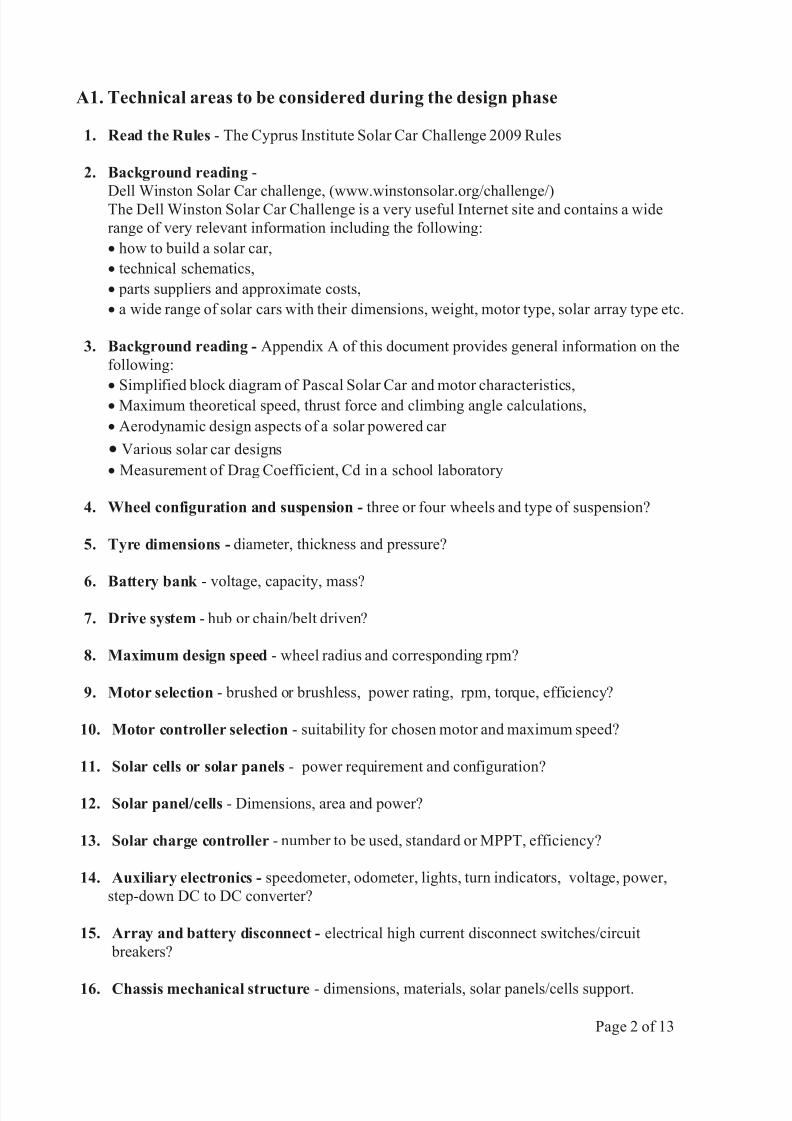
A1. Technical areas to be considered during the design phase
1. Read the Rules - The Cyprus Institute Solar Car Challenge 2009 Rules
2. Background reading -
Dell Winston Solar Car challenge, (www.winstonsolar.org/challenge/)The Dell Winston Solar Car Challenge is a very useful Internet site and contains a wide
range of very relevant information including the following:
· how to build a solar car,
· technical schematics,
· parts suppliers and approximate costs,
· a wide range of solar cars with their dimensions, weight, motor type, solar array type etc.
3. Background reading - Appendix A of this document provides general information on the
following:
· Simplified block diagram of Pascal Solar Car and motor characteristics,· Maximum theoretical speed, thrust force and climbing angle calculations,
· Aerodynamic design aspects of a solar powered car
· Various solar car designs
· Measurement of Drag Coefficient, Cd in a school laboratory
4. Wheel configuration and suspension - three or four wheels and type of suspension?
5. Tyre dimensions - diameter, thickness and pressure?
6. Battery bank - voltage, capacity, mass?
7. Drive system - hub or chain/belt driven?
8. Maximum design speed - wheel radius and corresponding rpm?
9. Motor selection - brushed or brushless, power rating, rpm, torque, efficiency?
10. Motor controller selection - suitability for chosen motor and maximum speed?
11. Solar cells or solar panels - power requirement and configuration?
12. Solar panel/cells - Dimensions, area and power?
13. Solar charge controller - number to be used, standard or MPPT, efficiency?
14. Auxiliary electronics - speedometer, odometer, lights, turn indicators, voltage, power,
step-down DC to DC converter?
15. Array and battery disconnect - electrical high current disconnect switches/circuit
breakers?
16. Chassis mechanical structure - dimensions, materials, solar panels/cells support.
Page 2 of 13
8/3/2019 Solar Car Design Guide Issue Logo
http://slidepdf.com/reader/full/solar-car-design-guide-issue-logo 4/14
A1. Technical areas to be considered during the design phase continued
17. Chassis and solar panels/cells arrangement - unified body and panel or separate cab and
panel (see Appendix A)
18 Breaking system- hydraulic or mechanical?
19. Parts salvage - are there any individual parts from broken down cars, scooters etc. that can
be potentially used in certain areas?
20. Solar car weight - estimated mass, acceleration, climbing capability?
21. Regenerative braking - what would be the benefits in this event and is it important to incorporate?
A2. Project Management
Among other aspects of managing the overall project by the various teams, the following areas need to be considered:
1. Team structure - how many people and their responsibilities (task allocation)?
2. Race registration - how and what information is needed to register for the Cyprus Institute Solar
Car Challenge? See Paragraph A.3 on the next page.
3. Team training - how can the team members be made familiar with the design process and the
technical/practical skills required?
4. Location - Where will the construction take place?
5. Pricing of parts and datasheet collection - cost breakdown and manufacturers technical
documentation for the various parts (motor, batteries, charge controller/MPPT, motor
controller, solar panels/cells, other items or services).
6. Lead time of various parts - how long will it take to have the various parts available?
7. Time Plan - produce a time plan of the time required to complete the various activities until the
completion of the project.
8. Testing - at what stages will extensive tests be carried out and how much time should be
allocated?
9. Driver training - when and how?
10. Planning for the race - transportation of solar car etc.?
11. Safety - What safety steps need to be taken at each stage of testing and manufacturing? Who
would act as the safety officer and how would they be trained?
Page 3 of 13

8/3/2019 Solar Car Design Guide Issue Logo
http://slidepdf.com/reader/full/solar-car-design-guide-issue-logo 5/14
8/3/2019 Solar Car Design Guide Issue Logo
http://slidepdf.com/reader/full/solar-car-design-guide-issue-logo 6/14
A4. Funding Procedure
By 4th May 2009 all the documents listed in Paragraph A3 should have been received by CyI from the
various participating teams. Upon approval of these documents by 30th June 2009, the procedure to be
followed by CyI and the participating teams is as follows:
Stage 1
A sum of 3000 (three thousand) Eu will be issued to each of the approved teams Supervisor in order to
purchase some of the long lead items. The Team Supervisor will be required to sign a receipt which
will also indicate the team’s commitment to participate in the event.
Stage 2
Each team shall provide the following:
(a) Receipts for their initial 3000 Eu expenditure.
(b) A formal letter stating that the sum of 3500 Eu has been raised and briefly explaining how this wasachieved.
Upon acceptance of the above, CyI will issue a sum of 3500 (three thousand five hundred) Eu to the
respective Team Supervisor. The Team Supervisor will be required to sign a receipt which will also
indicate that no major problems have been encountered in their activities.
Stage 3
Each team shall provide the following:
(a) Receipts for their previous 3500 Eu expenditure.
(b) Formal progress report based on their initial schedule.
(c) A formal letter stating the amount of funds raised and briefly explaining how this was achieved.
Upon acceptance of the above, CyI will issue to the Team Supervisor a sum equal to the funds raised
during this stage but not exceeding 3500 (three thousand five hundred) Eu. The Team Supervisor will
be required to sign a receipt which will also indicate that no major problems have been encountered
and that the total expenditure for the project will not exceed 20K Eu.
Stage 4
The Team Supervisor will be required to submit receipts based on the previous 3500 Eu expenditure.
IMPORTANT NOTE:
All cheques issued by CyI will be made payable to the Supervisor’s Organization.
Page 5 of 13
8/3/2019 Solar Car Design Guide Issue Logo
http://slidepdf.com/reader/full/solar-car-design-guide-issue-logo 7/14
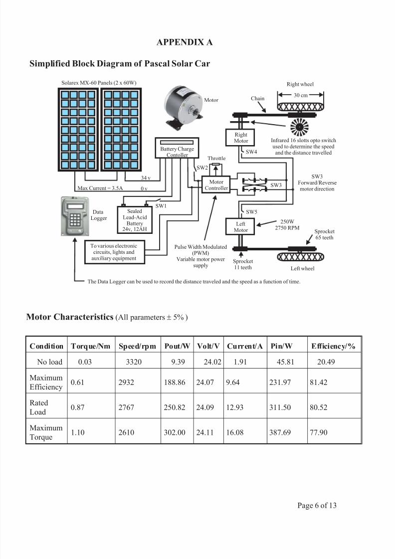
Simplified Block Diagram of Pascal Solar Car
LeftMotor
RightMotor
Battery ChargeContoller
Solarex MX-60 Panels (2 x 60W)
Chain
SealedLead-Acid
Battery24v, 12AH
250W2750 RPM
Sprocket11 teeth
Sprocket65 teeth
30 cm
Infrared 16 slotts opto switchused to determine the speed
and the distance travelled
0 v
34 v
Max Current = 3.5A
SW4
SW5
Motor Controller
SW3
Throttle
Pulse Width Modulated(PWM)
Variable motor power supply
SW3Forward/Reversemotor direction
SW1
SW2
To various electroniccircuits, lights and
auxiliary equipment
Left wheel
Right wheel
Motor
DataLogger
The Data Logger can be used to record the distance traveled and the speed as a function of time.
Motor Characteristics (All parameters ± 5% )
Condition Torque/Nm Speed/rpm Pout/W Volt/V Current/A Pin/W Efficiency/%
No load 0.03 3320 9.39 24.02 1.91 45.81 20.49
Maximum
Efficiency0.61 2932 188.86 24.07 9.64 231.97 81.42
Rated
Load0.87 2767 250.82 24.09 12.93 311.50 80.52
Maximum
Torque1.10 2610 302.00 24.11 16.08 387.69 77.90
APPENDIX A
Page 6 of 13

8/3/2019 Solar Car Design Guide Issue Logo
http://slidepdf.com/reader/full/solar-car-design-guide-issue-logo 8/14
In all the cases above, the values obtained correspond with only one motor operating. The effect of
having two motors operating in parallel needs to considered separately.Also, any resistive forces
such as rolling resistance aerodynamic drag and friction would need to be taken into consideration.
These aspects may be considered separately.
The situation on the right shows the solar car
attempting to climb up a slope. If the available
driving force is 34.3 N, then the angle q must be
such that the component of the weight acting down
the slope is less than 34.3 N. As given in the Solar
car specification, its mass is 73 kg. If the mass of the
driver is also assumed to be 73 kg, then,
mg sin q < 34.3
146 x 9.81 x sin q < 34.3
solving for q, gives that q < 1.31 °
qW = mg
m g s i n q
3 4 .3 N
APPENDIX A
Page 7 of 13
Maximum theoretical speed, thrust force and climbing angle
The maximum theoretical speed vmax
is give by,
v max = (motor rpm at rated load) x (gear reduction) x (wheel circumference)
= 2767 x11
65xp x 0.30
60= 7.4 ms -1 or 26.6 kmh-1
The maximum driving or thrust force F max is given by,
Torque = Fmax
x gear reduction x perpendicular distance
0.87 = Fmax
x11
65x 0.15
Solving for F max ,F
max= 34.3 N
8/3/2019 Solar Car Design Guide Issue Logo
http://slidepdf.com/reader/full/solar-car-design-guide-issue-logo 9/14
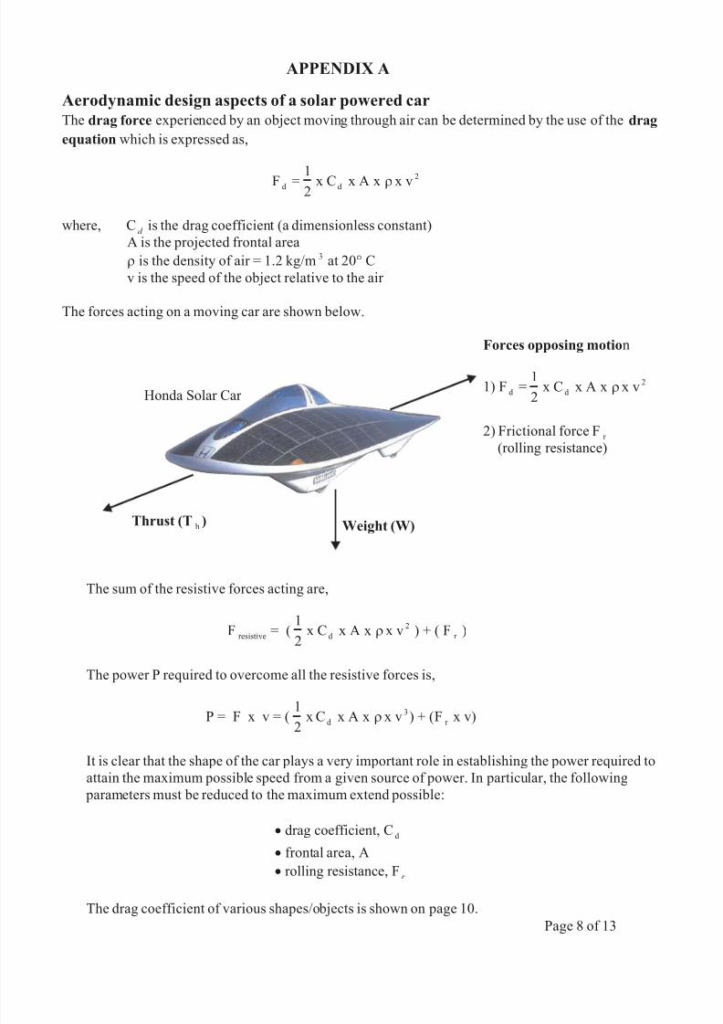
Forces opposing motion
1) Fd
=1
2x C x A x x vd
2r
2) Frictional force Fr
(rolling resistance)
Weight (W)Thrust (Th
)
The sum of the resistive forces acting are,
Fresistive
= (1
2x C x A x x v
d
2r ) + ( Fr
)
The power P required to overcome all the resistive forces is,
P = F x v = (
1
2 x C x A x x vd
3
r ) + (F r x v)
It is clear that the shape of the car plays a very important role in establishing the power required to
attain the maximum possible speed from a given source of power. In particular, the following
parameters must be reduced to the maximum extend possible:
· drag coefficient, Cd
· frontal area, A
· rolling resistance, Fr
The drag coefficient of various shapes/objects is shown on page 10.
APPENDIX A
Page 8 of 13
Aerodynamic design aspects of a solar powered car
The drag force experienced by an object moving through air can be determined by the use of the drag
equation which is expressed as,
F d =1
2x C x A x x vd
2r
where, Cd
is the drag coefficient (a dimensionless constant)
A is the projected frontal area
r is the density of air = 1.2 kg/m 3 at 20° C
v is the speed of the object relative to the air
The forces acting on a moving car are shown below.
Honda Solar Car
8/3/2019 Solar Car Design Guide Issue Logo
http://slidepdf.com/reader/full/solar-car-design-guide-issue-logo 10/14
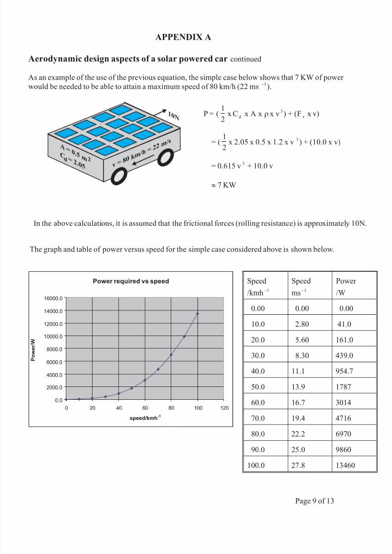
P = (1
2x C x A x x v
d
3r ) + (F r x v)
= (1
2x 2.05 x 0.5 x 1.2 x v 3 ) + (10.0 x v)
= 0.615 v 3 + 10.0 v
» 7 KW
A= 0.5 mdC
= 2.052
v = 80k m
/h= 22
m/s
10N
Aerodynamic design aspects of a solar powered car continued
As an example of the use of the previous equation, the simple case below shows that 7 KW of power
would be needed to be able to attain a maximum speed of 80 km/h (22 ms -1 ).
In the above calculations, it is assumed that the frictional forces (rolling resistance) is approximately 10N.
The graph and table of power versus speed for the simple case considered above is shown below.
Power required vs speed
0.0
2000.0
4000.0
6000.0
8000.0
10000.0
12000.0
14000.0
16000.0
0 20 40 60 80 100 120
speed/kmh-1
P o w e r / W
Speed
/kmh -1
Speed
ms -1
Power
/W
0.00 0.00 0.00
10.0 2.80 41.0
20.0 5.60 161.0
30.0 8.30 439.0
40.0 11.1 954.7
50.0 13.9 1787
60.0 16.7 3014
70.0 19.4 4716
80.0 22.2 6970
90.0 25.0 9860
100.0 27.8 13460
APPENDIX A
Page 9 of 13
8/3/2019 Solar Car Design Guide Issue Logo
http://slidepdf.com/reader/full/solar-car-design-guide-issue-logo 11/14
Power required vs speed
0.0
100.0
200.0
300.0
400.0
500.0
600.0
0 20 40 60 80 100 120
speed/kmh-1
P o w e r / W
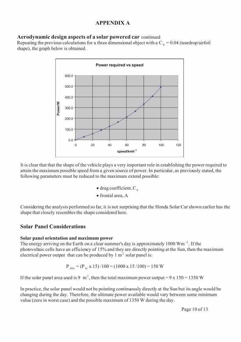
Aerodynamic design aspects of a solar powered car continued
Repeating the previous calculations for a three dimensional object with a Cd
= 0.04 (teardrop/airfoil
shape), the graph below is obtained.
It is clear that that the shape of the vehicle plays a very important role in establishing the power required to
attain the maximum possible speed from a given source of power. In particular, as previously stated, the
following parameters must be reduced to the maximum extend possible:
· drag coefficient, Cd
· frontal area, A
Considering the analysis performed so far, it is not surprising that the Honda Solar Car shown earlier has the
shape that closely resembles the shape considered here.
Solar Panel Considerations
Solar panel orientation and maximum powerThe energy arriving on the Earth on a clear summer's day is approximately 1000 Wm -2 . If the
photovoltaic cells have an efficiency of 15% and they are directly pointing at the Sun, then the maximum
electrical power output that can be produced by 1 m 2 solar panel is:
P max = (Pin
x 15) /100 = (1000 x 15 /100) = 150 W
If the solar panel area used is 9 m 2 , then the total maximum power output = 9 x 150 = 1350 W
In practice, the solar panel would not be pointing continuously directly at the Sun but its angle would be
changing during the day. Therefore, the ultimate power available would vary between some minimum
value (zero in worst case) and the possible maximum of 1350 W during the day.
APPENDIX A
Page 10 of 13
8/3/2019 Solar Car Design Guide Issue Logo
http://slidepdf.com/reader/full/solar-car-design-guide-issue-logo 12/14
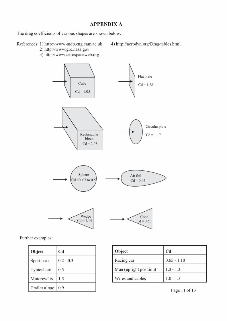
Cube
Cd = 1.05
Flat plate
Cd = 1.28
Sphere
Cd =0 .07 to 0.5
Circular plate
Cd = 1.17Rectangular block
Cd = 2.05
Air foil
Cd = 0.04
WedgeCd = 1.14
ConeCd = 0.50
Further examples:
Object Cd
Sports car 0.2 - 0.3
Typical car 0.5
Motorcyclist 1.5
Trailer alone 0.9
Object Cd
Racing car 0.65 - 1.10
Man (upright position) 1.0 - 1.3
Wires and cables 1.0 - 1.3
APPENDIX A
Page 11 of 13
The drag coefficients of various shapes are shown below.
References: 1) http://www-mdp.eng.cam.ac.uk 4) http://aerodyn.org/Drag/tables.html
2) http://www.grc.nasa.gov
3) http://www.aerospaceweb.org

8/3/2019 Solar Car Design Guide Issue Logo
http://slidepdf.com/reader/full/solar-car-design-guide-issue-logo 13/14
Various solar car designs (separate cab and panel)
APPENDIX A
Various solar car designs (unified airfoil body and panel)
Page 12 of 13
8/3/2019 Solar Car Design Guide Issue Logo
http://slidepdf.com/reader/full/solar-car-design-guide-issue-logo 14/14
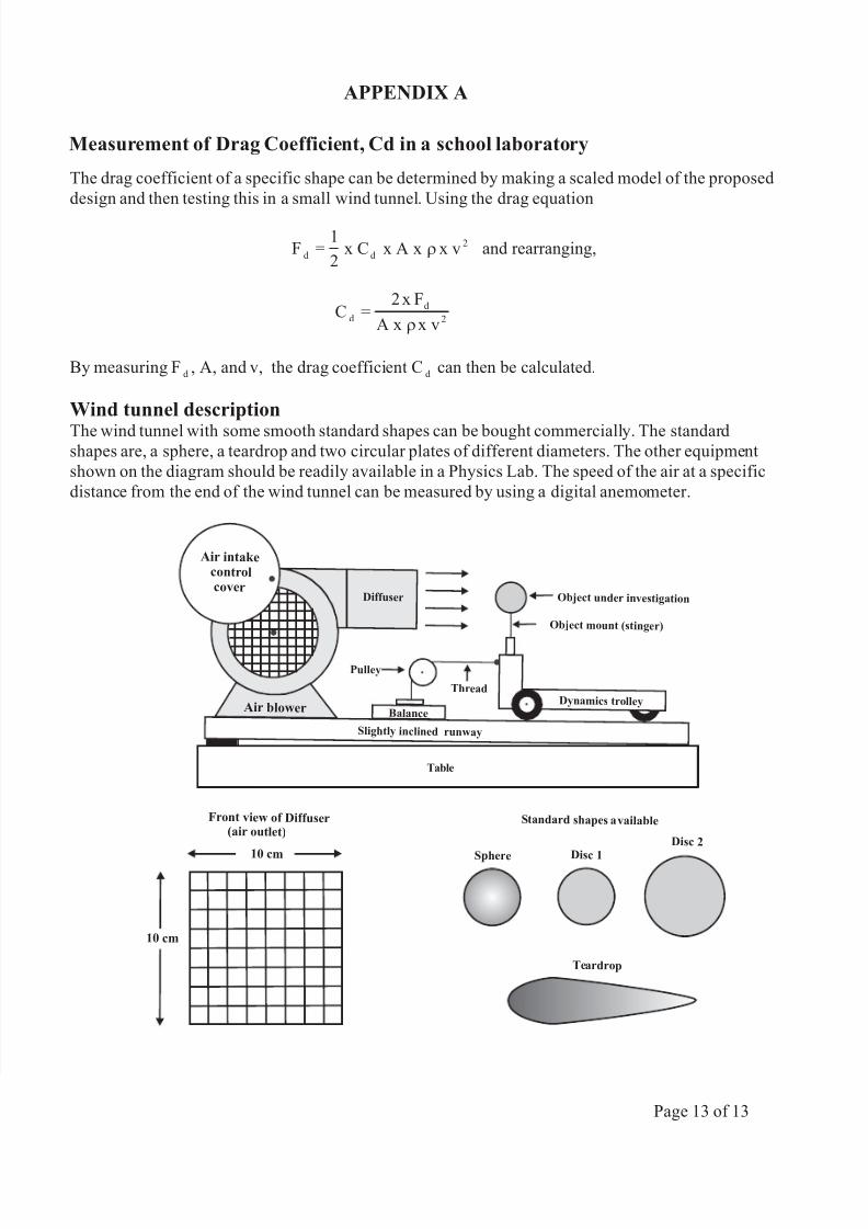
Measurement of Drag Coefficient, Cd in a school laboratory
The drag coefficient of a specific shape can be determined by making a scaled model of the proposed
design and then testing this in a small wind tunnel. Using the drag equation
Fd
=1
2x C x A x x v
d
2r and rearranging,
Cd
=2 x F
A x x v
d
2r
By measuring Fd
, A, and v, the drag coefficient Cd
can then be calculated.
Wind tunnel description
The wind tunnel with some smooth standard shapes can be bought commercially. The standardshapes are, a sphere, a teardrop and two circular plates of different diameters. The other equipment
shown on the diagram should be readily available in a Physics Lab. The speed of the air at a specific
distance from the end of the wind tunnel can be measured by using a digital anemometer.
BalanceAir blower
Dynamics trolley
Ob ject under investigation
Table
Pulley
Thread
Slightly inclined runway
Air intak econtrolcover
Dif fuser
Object mount (stinger)
SphereDis
c 1
Teardrop
Standard shapes available
Disc 2
Front view of Dif f user(air outlet)
10 cm
10 cm
APPENDIX A
Page 13 of 13