Smoke Control Manual For KMC Conquest Systems
48
Smoke Control Manual For KMC Conquest Systems KMC Controls, 19476 Industrial Drive, New Paris, IN 46553 / 877.444.5622 / Fax: 574.831.5252 / www.kmccontrols.com
Transcript of Smoke Control Manual For KMC Conquest Systems

Smoke Control Manual for KMC Conquest Systems 1 000-035-18B
Smoke Control Manual
For KMC Conquest Systems
KMC Controls, 19476 Industrial Drive, New Paris, IN 46553 / 877.444.5622 / Fax: 574.831.5252 / www.kmccontrols.com
Smoke Control Manual for KMC Conquest Systems 2 000-035-18B
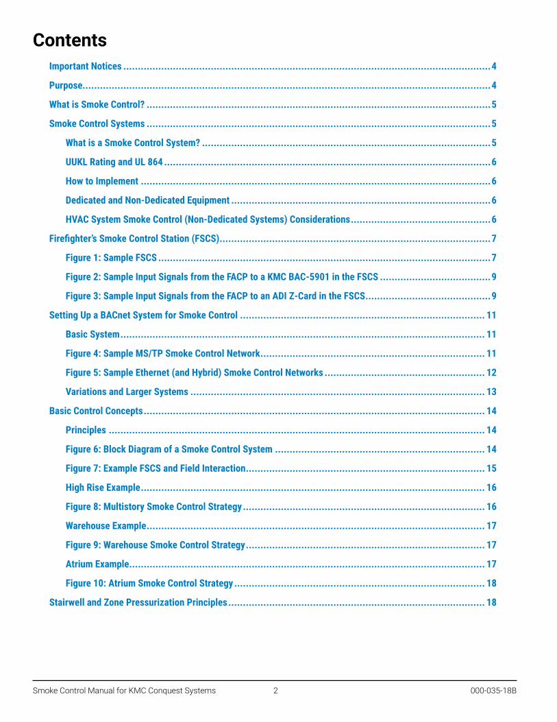
ContentsImportant Notices ..............................................................................................................................4
Purpose............................................................................................................................................4
What is Smoke Control? ......................................................................................................................5
Smoke Control Systems ......................................................................................................................5
What is a Smoke Control System? ...................................................................................................5
UUKL Rating and UL 864 ................................................................................................................6
How to Implement ........................................................................................................................6
Dedicated and Non-Dedicated Equipment .........................................................................................6
HVAC System Smoke Control (Non-Dedicated Systems) Considerations ................................................6
Firefighter’s Smoke Control Station (FSCS) .............................................................................................7
Figure 1: Sample FSCS ..................................................................................................................7
Figure 2: Sample Input Signals from the FACP to a KMC BAC-5901 in the FSCS ......................................9
Figure 3: Sample Input Signals from the FACP to an ADI Z-Card in the FSCS ...........................................9
Setting Up a BACnet System for Smoke Control .................................................................................... 11
Basic System ............................................................................................................................. 11
Figure 4: Sample MS/TP Smoke Control Network ............................................................................. 11
Figure 5: Sample Ethernet (and Hybrid) Smoke Control Networks ....................................................... 12
Variations and Larger Systems ..................................................................................................... 13
Basic Control Concepts ..................................................................................................................... 14
Principles ................................................................................................................................. 14
Figure 6: Block Diagram of a Smoke Control System ........................................................................ 14
Figure 7: Example FSCS and Field Interaction .................................................................................. 15
High Rise Example ...................................................................................................................... 16
Figure 8: Multistory Smoke Control Strategy ................................................................................... 16
Warehouse Example .................................................................................................................... 17
Figure 9: Warehouse Smoke Control Strategy .................................................................................. 17
Atrium Example .......................................................................................................................... 17
Figure 10: Atrium Smoke Control Strategy ...................................................................................... 18
Stairwell and Zone Pressurization Principles ........................................................................................ 18

Smoke Control Manual for KMC Conquest Systems 3 000-035-18B
Field Panels Wiring and Programming ................................................................................................. 19
Enclosure .................................................................................................................................. 19
Power Wiring ............................................................................................................................. 19
Figure 11: Installation Power Wiring .............................................................................................. 19
Approved Transformers ............................................................................................................... 20
Wiring and Terminal Blocks .......................................................................................................... 20
Wiring Controllers in an MS/TP Network ........................................................................................ 21
Figure 12: EIA-485 Network Wiring Details ..................................................................................... 21
Wiring Controllers in an Ethernet Network ...................................................................................... 22
Figure 13: Ethernet Network Wiring Option ..................................................................................... 22
Input and Output Wiring on Conquest Controllers and Devices ........................................................... 24
Figure 14: BAC-5900 Series Controller Typical Connections .............................................................. 24
Figure 15: CAN-5901 Module Typical Connections ........................................................................... 25
Figure 16: BAC-9300 Series Modules Typical Connections ................................................................ 26
Figure 17: BAC-5051E Router Connections ..................................................................................... 27
Programming the FSCS ............................................................................................................... 29
Programming Field Devices .......................................................................................................... 30
Writing at Priority 1 or 2 (Life Safety) in the BACnet Priority Array ..................................................... 31
Isolating the Smoke Control System from the HVAC System .............................................................. 31
Testing and Maintenance .................................................................................................................. 32
System Testing .......................................................................................................................... 32
Security and Maintenance of the System ........................................................................................ 33
Conclusion ...................................................................................................................................... 34
References ..................................................................................................................................... 35
Glossary ......................................................................................................................................... 36
Appendixes ..................................................................................................................................... 38
Device Electrical Ratings ............................................................................................................. 38
Air Handler Smoke Control Modes ................................................................................................. 41
Installation Instructions for FSCS Enclosures .................................................................................. 42
Sample FSCS and Field Panel Drawings .......................................................................................... 43

Smoke Control Manual for KMC Conquest Systems 4 000-035-18B
Important Notices©2020, KMC Controls, Inc.
All rights reserved. No part of this publication may be reproduced, transmitted, transcribed, stored in a retrieval system, or translated into any language in any form by any means without the written permission of KMC Controls.
The material in this document is for information purposes only. The contents and the product it describes are subject to change without notice.
KMC Controls, Inc. makes no representations or warranties with respect to this document. In no event shall KMC Controls, Inc. be liable for any damages, direct, or incidental, arising out of or related to the use of this document.
KMC Controls19476 Industrial DriveNew Paris, IN 46553U.S.A.TEL: 574.831.5250FAX: 574.831.8108EMAIL: [email protected]
PurposeThe purpose of this manual is to provide guidelines for control contractors (or system integrators) affiliated with KMC Controls when designing, programming, and installing KMC Conquest (Building Automation Control Network) equipment in a smoke control system.
This manual contains general information for KMC contractors/integrators on the subject of smoke management. It also provides details specific to interfacing KMC Conquest equipment with other parts of the building smoke management system. This manual includes topics on using KMC Conquest controllers to complete, test, and maintain a smoke control system.
NOTE: For specific information about the controllers and related equipment, see their respective data sheets and installation guides. (See References on page 35.)
The controllers will generally be involved in the portion of the smoke control system that operates space-conditioning equipment, such as air handlers and exhaust fans. These controllers may also be used in the Firefighters’ Smoke Control Station (FSCS).
Use of KMC Conquest controllers in any application requires special training. Contractors/integrators installing any KMC BACnet equipment are required to have attended a training course and have a solid knowledge of building automation. Smoke control system design is beyond the scope of the general BACnet training class or this guide. The design of a complete building smoke control system is a complex task that must be given great thought and planning by trained personnel.

Smoke Control Manual for KMC Conquest Systems 5 000-035-18B
What is Smoke Control?Smoke control within buildings refers to the method and system of manipulating smoke in the event of a fire. This is accomplished by using fans and dampers to control the movement of smoke. Smoke is composed of gas and small particles light enough to float in air. These properties allow smoke to be moved by guiding the air in and around a smoke-filled area. Based on automatic smoke detection, a zone containing burning material can be exhausted by fans to maintain a negative pressure. The intent is to keep the smoke from migrating to a lower pressure area within the building.
This is not always an easy task since the fire is producing heat that can cause pressures many times higher than normal building pressures. A building sprinkler system can reduce the heat produced by the fire and make smoke management systems far more effective. Sprinkler systems operate independently of smoke control systems.
To help contain the smoke, zones adjacent to the fire zone can be placed into a pressurization mode. In this mode, 100% outdoor air is supplied continuously to the areas adjacent to the fire zone while exhaust fans are disabled. This is just one method to contain the smoke. There are other methods depending on the control intent. (See, for example, Basic Control Concepts on page 14.) The method used is the decision of the company designing the project.
Smoke Control Systems
What is a Smoke Control System?A smoke control system is the combination of fans, dampers, warning devices, and other equipment that work together to perform the containment function for any smoke event at any location in a building. A properly designed smoke control system should inhibit or prevent the movement of smoke into areas of egress, exit, or other designated safe zones in a building.
Smoke control systems by necessity are building-specific. No two buildings will likely have exactly the same control requirements. The smoke control system will need to be carefully and thoroughly coordinated with the various other life safety systems in the building.
Smoke control sytems may not be necessary in every building. The decision to use a smoke control system may be based on the ability of the existing control and evacuation methods to:
• Save lives and prevent injury• Reduce property damage• Assist fire-fighting operations
A smoke control system is not a substitute for early smoke detection systems, well-marked exits, sprinkling systems, and an evacuation plan. These items should be considered the primary means of saving lives and reducing property damage. Smoke control can aid in the battle to save lives in the event of a fire by providing and maintaining a viable path of egress. Property damage can be minimized with a smoke control system by reducing the spread of smoke, a concept known as containment.

Smoke Control Manual for KMC Conquest Systems 6 000-035-18B
UUKL Rating and UL 864Underwriters Laboratories’ UUKL listing is a category code under UL 864, Control Units and Accessories for Fire Alarm Systems. UUKL is for products covered under the description “Smoke Control System Equipment.” Equipment that receives Underwriters Laboratories UUKL rating has been tested for integrity and long-term reliability. The equipment is subjected to extremes in temperature, humidity, and electrical transients and surges. This testing ensures that the devices will continuously perform even under severe and abnormal conditions.
How to ImplementBefore developing a smoke control system, determine the goals. Generally, the specific intent of a smoke control system is established in the job specifications. If questions or discrepancies concerning the specified sequence are found, work out these problems with the architect or designer as early as possible, preferably while engineering your portion of the job. This is the least expensive and most effective time to deal with life safety concerns.
Dedicated and Non-Dedicated EquipmentDedicated smoke control equipment is used for smoke manipulation only. This equipment only runs if there is a fire or a command from the FSCS. A dedicated piece of equipment can fail for some reason or become inoperable due to the power being shut off to the device. Since it is not used normally, the failure could go unnoticed until a periodic test is performed, which could be too late. Since it is not used on a daily basis, this equipment requires a weekly self-test to assure it is still in working order.
Non-dedicated smoke control equipment includes air-handling units, exhaust fans, and dampers used for daily control of space conditions for human comfort (temperature and humidity). If a failure occurs on non-dedicated equipment, the fault is more likely to get reported because occupants will complain about the space conditions. Also, a BACnet system can generate a number of different alarms to indicate some malfunction of the smoke control equipment. An air handler, for example, may be monitored for such conditions as differential pressure across the fan, current sensing on the motor, or for discharge temperature. Since the equipment is actually operating most of the time, valid information can be obtained daily or even hourly.
Alarms and occupant calls will highlight any equipment failure. Maintenance personnel are less likely to put the repair off for another day if occupants are complaining about the conditions. Thus, non-dedicated smoke control equipment is generally more reliable than dedicated equipment. KMC products are designed for non-dedicated smoke control systems.
HVAC System Smoke Control (Non-Dedicated Systems) ConsiderationsIn a system that is also used for human comfort control, smoke control functions must have the highest priority. In smoke control mode, all other building controls should be overridden. Hand-Off-Auto starter switches, freeze thermostats, duct smoke detectors, and other non-life-safety limits should be bypassed when the smoke control mode begins. The fan must run to failure in smoke control mode. However, high static limits, motor starter overloads, and other safety devices must not be bypassed. These devices, if bypassed, could create additional life and property hazards.
The air handler must be designed in such a way that the duct-pressure rating is not exceeded in smoke control mode. If the duct explodes, it will likely no longer provide effective smoke control. Special ducting or spring-loaded access doors may be necessary on high-pressure air handling systems. Coil bypass ductwork to protect coils from freezing in cold weather may also be necessary. While frozen coils may not be a high priority during a building fire, the ability to test the smoke control system without damaging the air handler is very desirable. Also, these considerations will allow recovery from false alarms without damage and downtime.

Smoke Control Manual for KMC Conquest Systems 7 000-035-18B
In a VAV system, additional sequencing may need to be added to prevent damage to ductwork that could result in a system failure. Terminal dampers should be driven open before the fan reaches its maximum speed. This will allow the air to be distributed safely to the necessary zone.
As the number of components in the signal path increases, so does the probability of a failure that will keep the end device from performing a desired action. Where life safety is involved, good practice is to keep it simple—fewer parts in series means a smaller chance of failure.
Even on well-planned construction jobs, equipment such as fire or smoke dampers can end up being covered by layers of conduit or other materials. Keep in mind on new construction that damper motors must be accessible for testing and maintenance in the future. The earlier changes can be made in the construction process the easier the task of modification or relocation for all parties involved.
Firefighter’s Smoke Control Station (FSCS)A Firefighter’s Smoke Control Station is the manual control center for all smoke control equipment in a building. It is usually installed at a main entrance or other easily accessible location. The panel front usually contains a diagram of the building with locations showing significant smoke control equipment. Switches allow the operator to modify the state of the equipment at each floor or zone. Indicators (colored LEDs) on the panel face display the status of the equipment. Any command that fails to execute properly results in an audible alarm and visual indicator.
Figure 1: Sample FSCS
As the name indicates, the operator is usually a firefighter who understands smoke control and can operate the panel in an effort to prevent loss of life and limit property damage. Manual commands given at the FSCS are the highest priority of any smoke control signal. The FSCS may control dedicated and/or non-dedicated smoke control equipment.

Smoke Control Manual for KMC Conquest Systems 8 000-035-18B
At the heart of the FSCS are the controllers. An FSCS may contain multiple controllers, with the number dependent on the point (monitored and controlled objects) requirements of the panel. The controllers are used to communicate to the control units in the field and read switch commands and display equipment status at the FSCS.
FSCS panels are usually “point hungry.” There is a high point density needed for a small area. An FSCS will typically require 6 to 8 inputs and 6 to 8 outputs for every zone. A 24 by 36 panel will only be able to control 12 to 16 zones and miscellaneous components. A zone generally is an area controlled by a single air-handling unit than can be placed into a control mode (e.g., pressurize or exhaust) from the FSCS.
Smoke control mode may be activated automatically, but it must also allow for a manual override option from the FSCS. The command for a certain action may come from a Fire Alarm Control Panel (FACP). After the requested action has completed, confirmation of the action by monitoring a feedback signal from the actuated device may be required. If the action needs to be performed manually, a switch (AUTO-MANUAL) must be available to do this, and the manual operation must take precedence over any other command. Any override switches would be on the FSCS located at an easy access point in the building such as the main entrance.
When constructing an FSCS allow for inputs for connections to a building’s FACP. Spare inputs in the FSCS should be wired to a terminal strip inside the panel. These terminals can then be used to allow dry contacts from the FACP to give automatic smoke control commands. Inputs from the FACP can be monitored by a BAC-5901 by KMC Controls or a Z-Card by ADI (Automation Displays, Inc.). (See Figure 2: Sample Input Signals from the FACP to a KMC BAC-5901 in the FSCS on page 9 and Figure 3: Sample Input Signals from the FACP to an ADI Z-Card in the FSCS on page 9.)
NOTE: Do not use fire alarm manual pull stations to initiate automatic smoke control sequences.
NOTE: Never tie in directly to a manual fire alarm pull-box to obtain location information on smoke zones. Tenants, customers, or employees at the site may pull the alarm in a zone far from the fire location. The smoke control system should receive input from the FACP, which will give commands based on heat, smoke, or sprinkler flow detection.
NOTE: The FSCS and the FACP must be installed within 20 feet of each other, they must be in the same room, and the wiring must be enclosed within conduit.

Smoke Control Manual for KMC Conquest Systems 9 000-035-18B
GND
UI3
UI5
UI4
UI6
GND
UI7
UI8
GND
UI9
UI10
GND
+B
-A MS
/TP
S
10/100E
THE
RN
ET
ON
OFF
EO
LON
OFFE
OL
+
S
EIO
–
FSCS
FACP
Figure 2: Sample Input Signals from the FACP to a KMC BAC-5901 in the FSCS
FSCS
FACP
????
Z-Card
Figure 3: Sample Input Signals from the FACP to an ADI Z-Card in the FSCS
Controller Inputs
Style “A“ (Class B) Contacts Only Initiating Circuit: 3 VDC nominal circuit voltage, 0.5 mA maximum short-circuit current, 5K ohms maximum line impedance (non-supervised).
(Contact ADI for Z-Card specifications)
NOTE: The FSCS and the FACP must be installed within 20 feet of each other, they must be in the same room, and the wiring must be enclosed within conduit connected to the controller’s enclosure.

Smoke Control Manual for KMC Conquest Systems 10 000-035-18B
Since the FSCS cover is the interface for firefighting personal, a graphic showing an overview of the building and smoke control system must be on the FSCS cover. The graphic should be a simplified building diagram with switches and indicators labeled for each zone. The graphic should clearly show where the smoke control equipment is located, what it can do, and what it currently is doing. The location of the FSCS in relation to the building layout must be clearly marked.
The operating capabilities of the equipment should be represented as modes of operation. For instance, putting an air handling unit into exhaust mode may involve shutting off the supply fan, outside damper, and return damper while starting the exhaust fan and opening the exhaust damper. Putting switches on the FSCS to perform each of these tasks individually can cause the panel to become complicated. Instead, a switch for each zone can be used to select a certain mode, and LEDs indicate each zone’s mode.
Common modes of operation are auto, pressurize, off, purge, and exhaust. Since no two modes can be on at the same time, a rotary switch can index all modes. Auto mode is the usual mode for all non-dedicated smoke control equipment.
All components used in the FSCS must be listed for smoke control use. These are components that have passed tests necessary to comply with UL standards for smoke control equipment.
All fans that part of the smoke control system must have a status indicator on the panel face. The fan status will come from differential air pressure sensing.
Also, wiring diagrams showing all connections that read the switch inputs and drive the LED outputs should be available. Indicate on the drawing that the boards will supply 12 VDC to power these LEDs.
KMC does not build FSCS panels, but KMC can assist in design and recommend suppliers authorized to build such panels. Allow at least 3 to 4 months for the application, material approval, and panel construction by a supplier.
An approved FSCS is constructed using 16 gauge steel. This UL listed panel comes with a lock on the cover to limit access to the internal components and power supply. The FSCS panel comes assembled with the following terminals for field wiring:
• 120 VAC power, 60 Hz, (VA requirement depends on the quantity of devices)• Network communications (for tying into remote devices; field-wiring for MS/TP communications requires
18 AWG twisted shielded pair)• Dry-contact inputs from the FACP
The FSCS mounting is not position sensitive. It should be mounted on a smooth, solid surface generally in a position with the door able to be opened from right to left. The panel has multiple knockouts to allow conduit attachment for running the 120 VAC power and other wiring specific to each job. Keep 120 VAC power lines separated from communications and other low voltage wires in the panel.
The FSCS should be equipped with both audible and visual indicators of communication and equipment problems. A means, such as a key switch, should be provided to silence audible alarms. The fault light, however, should remain on while a fault is detected, and if the fault is not cleared within 24 hours, the audible alarm should reactivate. Correcting the fault should automatically clear both the audible alarm and visual indicators.
When designing the smoke control system, transformers should be sized according to the requirements described in the device data sheets times the number of those devices.

Smoke Control Manual for KMC Conquest Systems 11 000-035-18B
Setting Up a BACnet System for Smoke Control
Basic SystemKMC Conquest controllers approved for smoke control use are the BAC-5900 and BAC-9300 series native BACnet Advanced Application Controllers. Programming and configuration of KMC Conquest controllers requires a PC with KMC Connect, KMC Converge, or TotalControl software. This software allows users to modify point data, view graphic displays, change programs, set user access levels, and view trend reports. A connected PC will also allow alarm messages to be printed for viewing and acknowledgment. The connected computer workstations are intended only for configuration and testing purposes, not for long-term monitoring of fire/smoke alarms.
FSCS
BAC-5051E BACnet Router
BAC-5051E BACnet Router
Controllers
Workstation Web Browser
To Other Controllerson the Smoke Control Network (Max. of 32
MS/TP Controllers on a Smoke Control Network)
Ethernet
MS/TP
Smoke Control Network on One MS/TP Trunk
Small System
Other MS/TP LANs(HVAC Control)
GN
D
UI3
UI5
UI4
UI6
GN
D
UI7
UI8
GN
D
UI9
UI1
0
GN
D
+B-A
MS/TP
S ON
OFF
EOL
ON
OFF
EOL
GN
D
UO
2
SC
UO
1
ROOMSENSOR
+ S
EIO–
GN
D
UO
4
SC
UO
3
GN
D
UO
6
SC
UO
5
GN
D
UO
8
SC
UO
7
General Purpose Controller
BACnet
24 VAC/VDCClass 250/60 HzMade in USA
1AOH
STATUS
2 3 4 5 6 7 8AOH
24 VAC/VDC ~ ––
GN
D
UI3
UI5
UI4
UI6
GN
D
UI7
UI8
GN
D
UI9
UI1
0
GN
D
+B-A
MS/TP
S ON
OFF
EOL
ON
OFF
EOL
GN
D
UO
2
SC
UO
1
ROOMSENSOR
+ S
EIO–
GN
D
UO
4
SC
UO
3
GN
D
UO
6
SC
UO
5
GN
D
UO
8
SC
UO
7
General Purpose Controller
BACnet
24 VAC/VDCClass 250/60 HzMade in USA
1AOH
STATUS
2 3 4 5 6 7 8AOH
24 VAC/VDC ~ ––
GN
D
UI3
UI5
UI4
UI6
GN
D
UI7
UI8
GN
D
UI9
UI1
0
GN
D
+B-A
MS/TP
S ON
OFF
EOL
ON
OFF
EOL
GN
D
UO
2
SC
UO
1
ROOMSENSOR
+ S
EIO–
GN
D
UO
4
SC
UO
3
GN
D
UO
6
SC
UO
5
GN
D
UO
8
SC
UO
7
General Purpose Controller
BACnet
24 VAC/VDCClass 250/60 HzMade in USA
1AOH
STATUS
2 3 4 5 6 7 8AOH
24 VAC/VDC ~ ––
GN
D
UI3
UI5
UI4
UI6
GN
D
UI7
UI8
GN
D
UI9
UI1
0
GN
D
+B-A
MS/TP
S ON
OFF
EOL
ON
OFF
EOL
GN
D
UO
2
SC
UO
1
ROOMSENSOR
+
S
EIO–
GN
D
UO
4
SC
UO
3
GN
D
UO
6
SC
UO
5
GN
D
UO
8
SC
UO
7
General Purpose Controller
BACnet
24 VAC/VDCClass 250/60 HzMade in USA
1AOH
STATUS
2 3 4 5 6 7 8AOH
24 VAC/VDC ~ ––
GN
D
UI3
UI5
UI4
UI6
GN
D
UI7
UI8
GN
D
UI9
UI1
0
GN
D
+B-A
MS/TP
S ON
OFF
EOL
ON
OFF
EOL
GN
D
UO
2
SC
UO
1
ROOMSENSOR
+
S
EIO–
GN
D
UO
4
SC
UO
3
GN
D
UO
6
SC
UO
5
GN
D
UO
8
SC
UO
7
General Purpose Controller
BACnet
24 VAC/VDCClass 250/60 HzMade in USA
1AOH
STATUS
2 3 4 5 6 7 8AOH
24 VAC/VDC ~ ––
GN
D
UI3
UI5
UI4
UI6
GN
D
UI7
UI8
GN
D
UI9
UI1
0
GN
D
+B-A
MS/TP
S ON
OFF
EOL
ON
OFF
EOL
GN
D
UO
2
SC
UO
1
ROOMSENSOR
+
S
EIO–
GN
D
UO
4
SC
UO
3
GN
D
UO
6
SC
UO
5
GN
D
UO
8
SC
UO
7
General Purpose Controller
BACnet
24 VAC/VDCClass 250/60 HzMade in USA
1AOH
STATUS
2 3 4 5 6 7 8AOH
24 VAC/VDC ~ ––
GN
D
UI3
UI5
UI4
UI6
GN
D
UI7
UI8
GN
D
UI9
UI1
0
GN
D
+B-A
MS/TP
S ON
OFF
EOL
ON
OFF
EOL
GN
D
UO
2
SC
UO
1
ROOMSENSOR
+ S
EIO–
GN
D
UO
4
SC
UO
3
GN
D
UO
6
SC
UO
5
GN
D
UO
8
SC
UO
7
General Purpose Controller
BACnet
24 VAC/VDCClass 250/60 HzMade in USA
1AOH
STATUS
2 3 4 5 6 7 8AOH
24 VAC/VDC ~ ––
GN
D
UI3
UI5
UI4
UI6
GN
D
UI7
UI8
GN
D
UI9
UI1
0
GN
D
+B-A
MS/TP
S ON
OFF
EOL
ON
OFF
EOL
GN
D
UO
2
SC
UO
1
ROOMSENSOR
+ S
EIO–
GN
D
UO
4
SC
UO
3
GN
D
UO
6
SC
UO
5
GN
D
UO
8
SC
UO
7
General Purpose Controller
BACnet
24 VAC/VDCClass 250/60 HzMade in USA
1AOH
STATUS
2 3 4 5 6 7 8AOH
24 VAC/VDC ~ ––
GN
D
UI3
UI5
UI4
UI6
GN
D
UI7
UI8
GN
D
UI9
UI1
0
GN
D
+B-A
MS/TP
S ON
OFF
EOL
ON
OFF
EOL
GN
D
UO
2
SC
UO
1
ROOMSENSOR
+ S
EIO–
GN
D
UO
4
SC
UO
3
GN
D
UO
6
SC
UO
5
GN
D
UO
8
SC
UO
7
General Purpose Controller
BACnet
24 VAC/VDCClass 250/60 HzMade in USA
1AOH
STATUS
2 3 4 5 6 7 8AOH
24 VAC/VDC ~ ––
FACP
Figure 4: Sample MS/TP Smoke Control Network

Smoke Control Manual for KMC Conquest Systems 12 000-035-18B
For smoke control, the maximum possible number of controllers in a particular installation is highly dependent on the network configuration and how the FSCS is implemented. The following are KMC’s recommendations for optimized MS/TP BACnet UUKL approved controller installations:
• The maximum number of KMC controllers (with optimized programming and on an optimized network) is 60 (including the controllers inside the FSCS).
• Inside the FSCS, one controller must be dedicated to monitor alarms from the FACP.• If you need more than 16 zones, contact KMC Controls for assistance.• Each controller can query no more than 3 network points (requests from one controller to another of a
read or write property of a BACnet object).• All BACnet controllers involved in a smoke control system should be limited to one MS/TP trunk.• The maximum wire length for EIA-485 MS/TP networks in a smoke control system is 4,000 feet total.• A KMC KMD-5567 surge suppressor (not shown in the illustration above) must be installed on the MS/
TP line at every controller and router involved in a smoke control system as well as anywhere the MS/TP cable enters or leaves the building.
MS/TP Controllers
BAC-5051E BACnet Routers
EIS8-100T Ethernet Switch
FSCSFACP
Smoke Control Network on Ethernet and Three MS/TP Trunks
To Other Controllers
on the Smoke Control Network
(Max. of 32 Controllers per Trunk)
Ethernet
Workstation Web Browser
Larger System
BAC-5051E BACnet Router
Other MS/TP LANs(HVAC Control)
GN
DU
I3
UI5
UI4
UI6
GN
D
UI7
UI8
GN
D
UI9
UI1
0G
ND
+B-A
MS/TP
S ON
OFF
EOL
ON
OFF
EOL
GN
DU
O2
SCUO
1
ROOMSENSOR
+ S
EIO–
GN
DU
O4
SCUO
3
GN
DU
O6
SCUO
5
GN
DU
O8
SCUO
7
General Purpose Controller
BACnet
24 VAC/VDCClass 250/60 HzMade in USA
1AOH
STATUS
2 3 4 5 6 7 8AOH
24 VAC/VDC ~ ––
GN
DU
I3
UI5
UI4
UI6
GN
D
UI7
UI8
GN
D
UI9
UI1
0G
ND
+B-A
MS/TP
S ON
OFF
EOL
ON
OFF
EOL
GN
DU
O2
SCUO
1
ROOMSENSOR
+ S
EIO–
GN
DU
O4
SCUO
3
GN
DU
O6
SCUO
5
GN
DU
O8
SCUO
7
General Purpose Controller
BACnet
24 VAC/VDCClass 250/60 HzMade in USA
1AOH
STATUS
2 3 4 5 6 7 8AOH
24 VAC/VDC ~ ––
GN
DU
I3
UI5
UI4
UI6
GN
D
UI7
UI8
GN
D
UI9
UI1
0G
ND
+B-A
MS/TP
S ON
OFF
EOL
ON
OFF
EOL
GN
DU
O2
SCUO
1
ROOMSENSOR
+ S
EIO–
GN
DU
O4
SCUO
3
GN
DU
O6
SCUO
5
GN
DU
O8
SCUO
7
General Purpose Controller
BACnet
24 VAC/VDCClass 250/60 HzMade in USA
1AOH
STATUS
2 3 4 5 6 7 8AOH
24 VAC/VDC ~ ––
GN
DU
I3
UI5
UI4
UI6
GN
D
UI7
UI8
GN
D
UI9
UI1
0G
ND
+B-A
MS/TP
S ON
OFF
EOL
ON
OFF
EOL
GN
DU
O2
SCUO
1
ROOMSENSOR
+ S
EIO–
GN
DU
O4
SCUO
3
GN
DU
O6
SCUO
5
GN
DU
O8
SCUO
7
General Purpose Controller
BACnet
24 VAC/VDCClass 250/60 HzMade in USA
1AOH
STATUS
2 3 4 5 6 7 8AOH
24 VAC/VDC ~ ––
GN
DU
I3
UI5
UI4
UI6
GN
D
UI7
UI8
GN
D
UI9
UI1
0G
ND
+B-A
MS/TP
S ON
OFF
EOL
ON
OFF
EOL
GN
DU
O2
SCUO
1
ROOMSENSOR
+ S
EIO–
GN
DU
O4
SCUO
3
GN
DU
O6
SCUO
5
GN
DU
O8
SCUO
7
General Purpose Controller
BACnet
24 VAC/VDCClass 250/60 HzMade in USA
1AOH
STATUS
2 3 4 5 6 7 8AOH
24 VAC/VDC ~ ––
GN
DU
I3
UI5
UI4
UI6
GN
D
UI7
UI8
GN
D
UI9
UI1
0G
ND
+B-A
MS/TP
S ON
OFF
EOL
ON
OFF
EOL
GN
DU
O2
SCUO
1
ROOMSENSOR
+ S
EIO–
GN
DU
O4
SCUO
3
GN
DU
O6
SCUO
5
GN
DU
O8
SCUO
7
General Purpose Controller
BACnet
24 VAC/VDCClass 250/60 HzMade in USA
1AOH
STATUS
2 3 4 5 6 7 8AOH
24 VAC/VDC ~ ––
GN
DU
I3
UI5
UI4
UI6
GN
D
UI7
UI8
GN
D
UI9
UI1
0G
ND
+B-A
MS/TP
S ON
OFF
EOL
ON
OFF
EOL
GN
DU
O2
SCUO
1
ROOMSENSOR
+ S
EIO–
GN
DU
O4
SCUO
3
GN
DU
O6
SCUO
5
GN
DU
O8
SCUO
7
General Purpose Controller
BACnet
24 VAC/VDCClass 250/60 HzMade in USA
1AOH
STATUS
2 3 4 5 6 7 8AOH
24 VAC/VDC ~ ––
GN
DU
I3
UI5
UI4
UI6
GN
D
UI7
UI8
GN
D
UI9
UI1
0G
ND
+B-A
MS/TP
S ON
OFF
EOL
ON
OFF
EOL
GN
DU
O2
SCUO
1
ROOMSENSOR
+ S
EIO–
GN
DU
O4
SCUO
3
GN
DU
O6
SCUO
5
GN
DU
O8
SCUO
7
General Purpose Controller
BACnet
24 VAC/VDCClass 250/60 HzMade in USA
1AOH
STATUS
2 3 4 5 6 7 8AOH
24 VAC/VDC ~ ––
GN
DU
I3
UI5
UI4
UI6
GN
D
UI7
UI8
GN
D
UI9
UI1
0G
ND
+B-A
MS/TP
S ON
OFF
EOL
ON
OFF
EOL
GN
DU
O2
SCUO
1
ROOMSENSOR
+ S
EIO–
GN
DU
O4
SCUO
3
GN
DU
O6
SCUO
5
GN
DU
O8
SCUO
7
General Purpose Controller
BACnet
24 VAC/VDCClass 250/60 HzMade in USA
1AOH
STATUS
2 3 4 5 6 7 8AOH
24 VAC/VDC ~ ––
Ethernet Controllers
EIS8-100T Ethernet Switches
Ethernet
Smoke Control Network on Ethernet Trunks
To Other LANs(HVAC Control)
To Other Controllers
and Switches
on the Smoke Control Network
10/100ETHERNET G
ND
UI3
UI5
UI4
UI6
GN
D
UI7
UI8
GN
D
UI9
UI1
0G
ND
ON
OFF
EOL
GN
DU
O2
SCUO
1
ROOMSENSOR
+ S
EIO–
GN
DU
O4
SCUO
3
GN
DU
O6
SCUO
5
GN
DU
O8
SCUO
7
General Purpose Controller
BACnet
24 VAC/VDCClass 250/60 HzMade in USA
1AOH
STATUS
2 3 4 5 6 7 8AOH
24 VAC/VDC ~ ––
10/100ETHERNET G
ND
UI3
UI5
UI4
UI6
GN
D
UI7
UI8
GN
D
UI9
UI1
0G
ND
ON
OFF
EOL
GN
DU
O2
SCUO
1
ROOMSENSOR
+ S
EIO–
GN
DU
O4
SCUO
3
GN
DU
O6
SCUO
5
GN
DU
O8
SCUO
7
General Purpose Controller
BACnet
24 VAC/VDCClass 250/60 HzMade in USA
1AOH
STATUS
2 3 4 5 6 7 8AOH
24 VAC/VDC ~ ––
10/100ETHERNET G
ND
UI3
UI5
UI4
UI6
GN
D
UI7
UI8
GN
D
UI9
UI1
0G
ND
ON
OFF
EOL
GN
DU
O2
SCUO
1
ROOMSENSOR
+ S
EIO–
GN
DU
O4
SCUO
3
GN
DU
O6
SCUO
5
GN
DU
O8
SCUO
7
General Purpose Controller
BACnet
24 VAC/VDCClass 250/60 HzMade in USA
1AOH
STATUS
2 3 4 5 6 7 8AOH
24 VAC/VDC ~ ––
Workstation Web Browser
Larger System
To Other Controllers
and Switches
on the Smoke Control Network
10/100ETHERNET G
ND
UI3
UI5
UI4
UI6
GN
D
UI7
UI8
GN
D
UI9
UI1
0G
ND
ON
OFF
EOL
GN
DU
O2
SCUO
1
ROOMSENSOR
+ S
EIO–
GN
DU
O4
SCUO
3
GN
DU
O6
SCUO
5
GN
DU
O8
SCUO
7
General Purpose Controller
BACnet
24 VAC/VDCClass 250/60 HzMade in USA
1AOH
STATUS
2 3 4 5 6 7 8AOH
24 VAC/VDC ~ ––
10/100ETHERNET G
ND
UI3
UI5
UI4
UI6
GN
D
UI7
UI8
GN
D
UI9
UI1
0G
ND
ON
OFF
EOL
GN
DU
O2
SCUO
1
ROOMSENSOR
+ S
EIO–
GN
DU
O4
SCUO
3
GN
DU
O6
SCUO
5
GN
DU
O8
SCUO
7
General Purpose Controller
BACnet
24 VAC/VDCClass 250/60 HzMade in USA
1AOH
STATUS
2 3 4 5 6 7 8AOH
24 VAC/VDC ~ ––
10/100ETHERNET G
ND
UI3
UI5
UI4
UI6
GN
D
UI7
UI8
GN
D
UI9
UI1
0G
ND
ON
OFF
EOL
GN
DU
O2
SCUO
1
ROOMSENSOR
+ S
EIO–
GN
DU
O4
SCUO
3
GN
DU
O6
SCUO
5
GN
DU
O8
SCUO
7
General Purpose Controller
BACnet
24 VAC/VDCClass 250/60 HzMade in USA
1AOH
STATUS
2 3 4 5 6 7 8AOH
24 VAC/VDC ~ ––
FSCSFACP
Figure 5: Sample Ethernet (and Hybrid) Smoke Control Networks
NOTE: The connected computer workstations are intended only for configuration and testing purposes, not for long-term monitoring of fire/smoke alarms.

Smoke Control Manual for KMC Conquest Systems 13 000-035-18B
The following are KMC’s recommendations for optimized Ethernet (BAC-5901CE and BAC-9300CE) installations:
• The maximum number of KMC controllers (with optimized programming and on an optimized network) is 60 (including the controllers inside the FSCS).
• Inside the FSCS, one controller must be dedicated to monitor alarms from the FACP.• If you need more than 16 zones, contact KMC Controls for assistance.• Each controller can query no more than 3 network points (requests from one controller to another of a
read or write property of a BACnet object).• A Contemporary Controls EIS8-100T Ethernet Switch is required for connecting to subnetworks. See the
Contemporary Controls EIS8-100T information for more details.• The maximum wire length for Ethernet networks in a smoke control system is 300 feet between
controllers.
Every controller involved in the smoke control scheme must receive the start-smoke-control-sequence command within ten seconds (as defined in section 6.4.3.6 of NFPA92). If more controllers and/or points are used, the MS/TP network may not meet timing requirements. Because of the smoke control system timing requirements, the maximum number of controllers is less than in a standard HVAC system. Moreover, this maximum is for an optimized system. If Control Basic programming is inefficient or read commands are more frequent than necessary, this may reduce the maximum number of controllers in a particular installation. For reading off-panel points without slowing down overall network traffic, use an interval (e.g., ten seconds) in Control Basic for reading such points.
Larger systems require Ethernet controllers since Ethernet is much faster than MS/TP communication.
Complete instructions for installing and optimizing networks is beyond the scope of this manual. The installer must be or become familiar with KMC BACnet systems. Training in installation and optimization of KMC BACnet systems is available from KMC Controls.
Variations and Larger SystemsUsing KMC controllers (alone) is suitable for smaller installations. For larger systems, however, the number of inputs and outputs in an FSCS can become cumbersome. Adding one or more Z-Card I/O Expansion Cards from ADI (Automation Displays, Inc.) helps simplify that aspect of the system. See Figure 3: Sample Input Signals from the FACP to an ADI Z-Card in the FSCS on page 9 and ADI (Automation Displays, Inc.) Z-Card information for more details about Z-Cards.
NOTE: A Z-Card requires a periodic test of the communications to prevent the Com Fail Light from coming on. A Control Basic program can be used to periodically trip a point for such a test.
A Z-card has a Modbus output. To interface with KMC BACnet, a 460MMBS-N34-D Real Time Automation Modbus to BACnet Gateway is used to translate protocols. See RTA (Real Time Automation) 460MMBS-N34-D information for more details.
NOTE: A Z-card and the RTA 460MMBS-N34-D devices are only used as a part of a complete FSCS and may or may not be used depending on the particular job. Contact Automation Displays, Inc. for your particular needs.

Smoke Control Manual for KMC Conquest Systems 14 000-035-18B
Basic Control Concepts
PrinciplesFigure 6: Block Diagram of a Smoke Control System on page 14 shows the simplest configuration for an FSCS being used in the smoke control loop.
FACP(or Manual Command)
FSCS
FieldController
Action
Proof
Command
Confirmation
Sensor orPull Switch Actuator
Motor
Feedback Potor Switch
NOTE: The FSCS and the FACP must be installed within 20 feet of each other, and the wiring must also be enclosed with conduit.
Figure 6: Block Diagram of a Smoke Control System
Commands may enter the FSCS automatically through an alarm initiated by an FACP. Only the first alarm from the FACP will be acted upon. Additional alarms will be ignored. It is necessary to ignore subsequent alarms and assume the first alarm is the actual smoke zone. Other alarms may occur if smoke crosses zone boundaries, but only the initial alarm remains active. An alarm from the FACP will be ignored if the FSCS has been placed in a smoke control mode manually from a firefighter.
The controller in the FSCS takes commands by reading switch positions set by the firefighter on the panel. Normally, all switches will remain in the “AUTO” position. In this mode, the FSCS panel is ignored by the HVAC system. Any switch moved from the “AUTO” position will result in a command being sent to the field controller and control device. These commands tell the field controller at the device which task or series of tasks to perform. The controller at the device sends signals out to actuators or relays to perform a given action. To complete the loop, proof of the desired action is sent back to the FSCS. The proof will come from a potentiometer or switch that makes contact when the device has reached the requested position. If the proof

Smoke Control Manual for KMC Conquest Systems 15 000-035-18B
of the action is not received within 60 seconds for fans or 75 seconds for dampers (per NFPA92 6.463.6.3), an audible alarm and visual indicator will be activated at the FSCS.
Figure 7: Example FSCS and Field Interaction on page 15 shows a damper with position feedback. The FSCS panel gives a command either from a manual switch or from an automatically activated condition (FACP). The command is transmitted on the network to the appropriate device. When the action has completed, the proof is transmitted back to the FSCS. The actuator shown is a “fail-safe” type, meaning it has the ability to drive the damper open or closed after failure of power. The actuators must be configured correctly to fail in the desired direction. (Examples in this manual may be different than any particular installation.)
Damper actuators used for smoke control should be UUKL approved and have the ability to provide feedback via approved end switches, potentiometers, or other devices. These feedback devices can be wired to tell the controller that the damper has been driven into position. After the damper actuator has been commanded to drive, an alarm should sound if the switch fails to complete the input circuit within the required time period.
Controller
Damper Actuator withPosition Feedback
* *
Figure 7: Example FSCS and Field Interaction
The construction of an FSCS is specific to each job site. The unit shown in Figure 1: Sample FSCS on page 7 and Figure 7: Example FSCS and Field Interaction on page 15 show a graphical representation of a building with mode control switches for each story and atrium. An example panel is detailed in Sample FSCS and Field Panel Drawings on page 43.
The controller is capable of reading analog signals of 0 to 12 VDC. An input configured as binary will read 0 volts as an ON condition (input shorted to the ground terminal) and full (3 volts across a pull-up resistor) voltage as an OFF condition (open). The voltage provided by the input can also be used for measuring passive devices (such as thermistors).
An emergency circuit should supply the AC line voltage to all devices in a smoke control system. An emergency circuit is generally fed by a generator or alternate source if the main power to the building is lost.

Smoke Control Manual for KMC Conquest Systems 16 000-035-18B
High Rise ExampleIn multistory buildings, a floor-by-floor containment approach is often chosen to control the flow of smoke. The floor at which the fire occurs will be placed in an exhaust mode to create a low pressure on that level. Floors above and below the smoke filled zone will be pressurized to prevent infiltration and allow time for occupants to escape safely. The stairwell is also pressurized so that occupants can leave any floor including the smoke-filled zone and enter a smoke-free passage to the outside. Stairwell pressurization can be from a constant volume fan in many applications, but in larger buildings this may need to be a variable speed or variable volume fan controlled by the static pressure at some point or points in the stairwell. If the pressure is too high, doors may not open properly, putting lives at risk. If the pressure is too low, due to doors being left open, smoke may enter the stairwell.
In the example shown in Figure 8: Multistory Smoke Control Strategy on page 16, a fire has started on the second floor. A command is sent out from the FSCS panel to activate the exhaust mode on that floor. A simple “Exhaust = ON” command is sent to the air handling unit controller on that floor. That local controller handles the logic of what to do in that mode. In this case, it has been programmed to run the exhaust fan and shut the supply fan off. The controllers on the first and third floors receive a “Pressurize = ON” command. The stairwell fan is also commanded to pressurize the stairwell tower.
Floor
ON
PressurizedAHU Controller
FSCS
VAV Controllers (Dampers Open)
OFF
FloorON
ExhaustedVAV Controllers
(Dampers Closed)
OFF
Floor
ON
PressurizedVAV Controllers (Dampers Open)
OFF
Fan Controller
ON
PressurizedStairwell
AHU Controller
AHU Controller
Figure 8: Multistory Smoke Control Strategy

Smoke Control Manual for KMC Conquest Systems 17 000-035-18B
Warehouse ExampleFor a warehouse or other building with large open areas and high ceilings, the smoke is exhausted from the top where it accumulates. The concept is to limit the depth of the smoke in order to increase the amount of time it takes to reach the escape paths.
In the example shown in Figure 9: Warehouse Smoke Control Strategy on page 17, the FSCS issues a command to the exhaust fan controller to pull smoke out of the upper area of the warehouse. At the same time, the supply fan located near the ground is instructed to bring in outside air to assist in smoke removal.
FSCS
ON
ON Controller
Controller
Figure 9: Warehouse Smoke Control Strategy
Atrium ExampleFor building atriums with large open areas, high ceilings, and exits to the outside of the building, the smoke is exhausted from the top where it accumulates. In the example shown in Figure 10: Atrium Smoke Control Strategy on page 18, the FSCS issues a command to the exhaust fan controllers to pull smoke out of the upper area of the atrium. At the same time, the ground level doors are opened (by a controller and actuator) to bring in outside air and to help evacuate occupants.

Smoke Control Manual for KMC Conquest Systems 18 000-035-18B
FSCS
ON
Controller
Controller
Doors Open
ON
Controller
Figure 10: Atrium Smoke Control Strategy
Stairwell and Zone Pressurization PrinciplesContractors designing smoke control systems must be very knowledgeable of smoke control principles. Such knowledge is beyond the scope of this manual. Refer to the latest version of NFPA92 Standard for Smoke-Control Systems Utilizing Barriers and Pressure Differences available on the National Fire Protection Agency’s web site (www.nfpa.org).

Smoke Control Manual for KMC Conquest Systems 19 000-035-18B
Field Panels Wiring and Programming
EnclosureFor smoke control applications, the controller must be mounted in a UL Listed FSCS enclosure or a listed enclosure with minimum dimensions. The minimum enclosure size is 16 x 18 x 6 inches. KMC enclosures HCO-1035 and HCO-1036 are approved for this application. (See also Installation Instructions for FSCS Enclosures on page 42.)
NOTE: Only one controller per enclosure.
Power WiringFigure 11: Installation Power Wiring on page 19 shows the mounting and wiring for a transformer and the power connector on a controller.
2"Min.
2" Min.
(L)(N)
PowerLimited
NotPowerLimited
PowerLimited
BranchCircuit
120 VAC15 A, 60 Hz
Provide 15 Amp Branch Circuit:120 VAC, 60 Hz, 60° C, Cu Wire 14 AWGPanel Disconnect Provided by Installer
Power Limited and Non-Power Limited wiring must be permanently separated by 2 inches (minimum) and shall be accomplished by clamping, routing, or equivalent means
Follow all local regulations and wiring codes when installing these products
Class 2 Wiring = Power Limited
PhaseCommon
24 VAC
Class 1 Wiring =Not Power Limited
GN
DU
I3
UI5
UI4
UI6
GN
D
UI7
UI8
GN
D
+B-A
MS/TP
S
10/100ETHERNETO
N
OFF
EOL
24 VAC/VDCSC BO6
BO5
ROOMSENSOR ~ ––
SC BO3
BO4
BO1
BO2
UO
7
UO
8U
O9
GN
DU
O10
GN
D
Controller
Figure 11: Installation Power Wiring

Smoke Control Manual for KMC Conquest Systems 20 000-035-18B
NOTE: All input and output devices must be within the same room as their connected controller, and the wiring from those devices must be inside conduit connected to the controller’s enclosure. All transformers (and their Class-2 24-VAC secondary voltage wiring) shall be inside the same enclosure as the controllers to which they supply power. All Class-1 supply voltage wiring to those transformers shall be inside conduit connected to the transformer’s and controller’s enclosure. Within the enclosure, the Class-1 supply voltage wiring shall be separate (by a minimum of 2 inches) from the power-limited Class-2 secondary voltage wiring and the input/output device wiring.
NOTE: See the corresponding installation guides for details of wiring the individual devices.
Approved TransformersUse only 24 VAC @ 60 Hz to power KMC Conquest controllers for smoke control applications, and use only approved transformers. KMC’s model XEE-6112-100 (120-to-24 VAC, 96 VA) transformer has been tested and approved for this application. All circuits, including supply voltage, are power limited. AC power is non-supervised in smoke control applications.
Wiring and Terminal BlocksController terminal blocks are removable for wiring convenience. Wire sizes 12–24 AWG can be clamped into each terminal. No more than two (16 AWG) wires can be joined at a common point.
NOTE: All circuits, including supply voltage, are power limited circuits.

Smoke Control Manual for KMC Conquest Systems 21 000-035-18B
Wiring Controllers in an MS/TP Network
S+B-A
S+B-A
S+B-A
End of
Line
End of
Line
Earth Grounded in One Place
Only
+B-A
S
+B-A
S
+B-A
S
Figure 12: EIA-485 Network Wiring Details
The MS/TP controllers are capable of communicating over shielded, two-wire, twisted pair, EIA-485 wiring. Figure 12: EIA-485 Network Wiring Details on page 21 shows the proper wiring for combining controllers on a network. The boards are wired together in a daisy-chain fashion. Any BACnet controller that has only 1 wire under the “A” terminal and 1 wire under the “B” terminal is considered to be an “End Of Line” unit, and the EOL switches should be turned on. All other boards must have End Of Line turned off. To maintain communications in case of an open conductor on the network cable, redundant wiring routed separately enhances reliability.
NOTE: Only two wires are allowed under each screw of an MS/TP terminal block.
NOTE: Loss of power or failure in one controller generally does not affect communications between the other daisy-chained MS/TP controllers on a network.
NOTE: Only UL 864 components can be connected to the smoke control network.
Smoke control schemes should allow for supervising the MS/TP EIA-485 network for integrity. The FSCS should be equipped with both audible and visual indication of communications problems. The ground fault impedance value for the supervised MS/TP EIA-485 communications circuit is 0 ohms.

Smoke Control Manual for KMC Conquest Systems 22 000-035-18B
A KMC KMD-5567 surge suppressor (NOT shown in Figure 12: EIA-485 Network Wiring Details on page 21) must be installed on the MS/TP line at every controller and router involved in a smoke control system as well as anywhere the MS/TP cable enters or leaves the building. See also Setting Up a BACnet System for Smoke Control on page 11.
Wiring Controllers in an Ethernet Network
Star Topology
EIS8-100T Switch
Conquest Controllers
Figure 13: Ethernet Network Wiring Option
Ethernet networks provide much faster communication than MS/TP networks. See Figure 13: Ethernet Network Wiring Option on page 22 and Figure 5: Sample Ethernet (and Hybrid) Smoke Control Networks on page 12.
NOTE: The connected computer workstations are intended only for configuration and testing purposes, not for long-term monitoring of fire/smoke alarms.
NOTE: For smoke control systems, use a star topology (not daisy chain) for Ethernet controller connections.
In large installations, a star topology usually requires more Ethernet switches (i.e., Contemporary Controls EIS8-100T) and longer lengths of wiring than a daisy chain topology. A star topology, however, provides maximum redundancy against a failure in system communication/control because of a sudden loss of power or damage to a controller during a fire. The disabling of one controller does not affect the other controllers in a star topology.

Smoke Control Manual for KMC Conquest Systems 23 000-035-18B
Smoke control systems should allow for supervising the Ethernet network for integrity. The FSCS should be equipped with both audible and visual indication of communications problems. The ground fault impedance value for the supervised Ethernet communications circuit is 0 ohms.
NOTE: A Transtector Data Line Surge Protector P/N 1101-1001 (not shown in the illustration above) must be installed on the Ethernet line at every controller and router involved in a smoke control system as well as anywhere the Ethernet cable enters or leaves the building.
NOTE: Only UL 864 components can be connected to the smoke control network.

Smoke Control Manual for KMC Conquest Systems 24 000-035-18B
Input and Output Wiring on Conquest Controllers and Devices
BLK
SHLD
SHLD
RED
ControllerNextTo
EthernetTo
ControllerPrevious
From
BLKR
ED
NOTE: Use 24 VAC (only) with triac outputs (HPO-6701 output override boards on a BAC-5900 series controller).
NOTE: For MS/TP wiring, turn the End Of Line switch ON at both physical ends of the network (one wire under each terminal). Connect the cable shield to earth ground at only one point.
NOTE: Use only KMC XEE-6112-100 transformers (24 VAC @ 60 Hz) to power KMC Conquest controlllers for smoke control applications. All circuits are power limited.
NOTE: For Ethernet models, connect the controller to the network with a standard Ethernet patch cord.
NOTE: Only two wires are allowed under each screw of an MS/TP terminal block. For the redundant wiring option, a wire nut or splice will need to be added for all connections that are not End of Line.
NOTE: Analog inputs accept dry contacts, 1K or 10K sensors, 0–12 VDC, or 4–20 mA.
Transtector
KMD-5567
NOTE: To use an override board instead of the default universal output on a BAC-5900 series controller, remove the jumper and insert a board in that slot. For more information, see the installation guide for the HPO-6700 output override board series.
NOTE: All output and input devices must be within the same room as their connected controller, and the wiring from those devices must be inside conduit connected to the controller’s enclosure.
JumpersOverride Boards
LineVoltage
24VAC
+ –
0–10 VDCDevice (onUniversalOutput)
GN
DU
I3
UI5
UI4
UI6
GN
D
UI7
UI8
GN
D
UI9
UI1
0G
ND
+B-A
MS/TP
S
10/100ETHERNET O
N
OFF
EOL
ON
OFF
EOL
+ –
4–20 mADevice
(onHPO-6704)
To OptionalCAN-5901
I/O ExpansionModule(s)
(must be in thesame room)
BLK
RED
SHLD
CAUTION: Do NOT connect 24 VAC to the BAC-5900 series outputs unless an HPO-6701 is installed!
NOTE: All circuits are power limited.
GN
DU
O2
SCUO
1
ROOMSENSOR
+ S
EIO–
GN
DU
O4
SCUO
3
GN
DU
O6
SCUO
5
GN
DU
O8
SCUO
7
General Purpose Controller
BACnet
24 VAC/VDCClass 250/60 HzMade in USA
1AOH
STATUS
2 3 4 5 6 7 8AOH
24 VAC/VDC ~ ––
H N
Phase Neutral
1 2 3 4 5 6 7 8
H
N
Contactor (on
HPO-6701 Triac)
LINE
EQUIP
GROUND
Figure 14: BAC-5900 Series Controller Typical Connections

Smoke Control Manual for KMC Conquest Systems 25 000-035-18B
NOTE: Up to four CAN-5901 I/O expansion modules can be used with BAC-5900 series controllers to provide up to (internal and external) 42 inputs and 40 outputs.
NOTE: For EIO wiring, turn the End Of Line switch ON at both physical ends of the network (one wire under each terminal). Connect the cable shield to earth ground at only one point.
LineVoltage
24VAC
+ –
0–10 VDCDevice (onUniversalOutput)
+ –
4–20 mADevice
(onHPO-6704)
H N
Phase Neutral
H
N
Contactor (on
HPO-6701 Triac)
NOTE: Use 24 VAC (only) with triac outputs (HPO-6701 output override boards on a CAN-5901 series controller).
NOTE: To use an override board instead of the default universal output on a CAN-5901 series controller, remove the jumper and insert a board in that slot. For more information, see the installation guide for the HPO-6700 output override board series.
NOTE: For smoke control applications, the CAN-5901 module and all output and input devices must be within the same room as their connected controller, and the wiring from those devices must be inside conduit connected to the controller’s enclosure.
JumpersOverride Boards
CAUTION: Do NOT connect 24 VAC to the CAN-5901 outputs unless an HPO-6701 is installed!
1 2 3 4 5 6 7 8
NOTE: Use only KMC XEE-6112-100 transformers (24 VAC @ 60 Hz) to power KMC Conquest controlllers for smoke control applications. All circuits are power limited.
GN
DU
O2
SCUO
1
GN
DU
O4
SCUO
3
GN
DU
O6
SCUO
5
GN
DU
O8
SCUO
7 24 VAC/VDC ~ ––
GN
DU
I1
UI3
UI2
UI4
GN
D
UI5
UI6
GN
D
UI7
UI8
GN
D
ON
OFF
EOL
+ S
EIO–
BLKSH
LD
RED
BLKR
ED
SHLD
FromBAC-5901Controller CAN-5901
NextTo
IO Module
Expansion
24 VAC/VDCClass 250/60 HzMade in USA
1AOH
STATUS
2 3 4 5 6 7 8AOH
NOTE: Cable shields are connected to each other and grounded at one end only.
NOTE: All circuits are power limited.
Figure 15: CAN-5901 Module Typical Connections

Smoke Control Manual for KMC Conquest Systems 26 000-035-18B
GN
DU
I3
UI5
UI4
UI6
GN
D
UI7
UI8
GN
D
+B-A
MS/TP
S
10/100ETHERNETO
N
OFF
EOL
PRESSURESENSOR
HIGH LOW
NOTE: Use 24 VAC (only) on triac outputs (BO1–BO6 with SCs)!
CAUTION: Do NOT connect 24 VAC to the analog outputs (UO7–UO10 and GNDs)!
NOTE: For MS/TP models, turn the End Of Line switch ON at both physical ends of the MS/TP network. Connect the cable shield to earth ground at only one point.
NOTE: For Ethernet models, connect the controller to the network with a standard Ethernet patch cord.
BAC-9300 Series Controller
LH
1/4" (6.35) FR tubing
to flow sensor
24 VAC/VDCSC BO6
BO5
ROOMSENSOR
HN LineVoltage
24 VAC
FanStart
~~
COM
PhaseNeutral
~ ––
–
SC BO3
BO4
BO1
BO2
NOTE: Use only KMC XEE-6112-100 transformers (24 VAC @ 60 Hz) to power KMC Conquest controlllers for smoke control applications. All circuits are power limited.
UO
7
UO
8U
O9
GN
DU
O10
GN
D
–+
ModReheat
NOTE: MS/TP cable shields are connected to each other and grounded at one end only.
NOTE: All output and input devices must be within the same room as their connected controller, and the wiring from those devices must be inside conduit connected to the controller’s enclosure.
BLK
SHLD
SHLD
RED
ControllerNextTo
EthernetTo
ControllerPrevious
From
BLKR
ED
NOTE: Analog inputs accept dry contacts, 1K or 10K sensors, 0–12 VDC, or 4–20 mA.
Transtector
KMD-5567
LINE
EQUIP
GROUNDNOTE: Only two wires are allowed under each screw of an MS/TP terminal block. For the redundant wiring option, a wire nut or splice will need to be added for all connections that are not End of Line.
Figure 16: BAC-9300 Series Modules Typical Connections

Smoke Control Manual for KMC Conquest Systems 27 000-035-18B
NOTE: Turn the End Of Line (EOL) switch ON at both physical ends of the MS/TP network. Otherwise, it should be OFF.
NOTE: Use Ethernet patch cords for the Ethernet network connections.
To Ethernet NetworkMS/TP Network
HN LineVoltage
24 VAC
~PhaseNeutral
–
NOTE: Use only KMC XEE-6112-100 transformers (24 VAC @ 60 Hz) to power KMC BAC-5051E routers for smoke control applications. All circuits are power limited.
+B-A
BACnet MS/TP
S
COMMREADY
EOL
ON
OFF
USB NETWORK
NOTE: MS/TP cable shields are connected to each other and grounded at one end only.
BLK
SHLD
SHLD
RED
ControllerNextTo
ControllerPrevious
FromBLKR
ED
Transtector
KMD-5567 LINE
EQUIP
GROUND
NOTE: Only two wires are allowed under each screw of an MS/TP terminal block. For the redundant wiring option, a wire nut or splice will need to be added for all connections that are not End of Line.
Figure 17: BAC-5051E Router ConnectionsThe input terminal blocks are located on the bottom when oriented as in Figure 14: BAC-5900 Series Controller Typical Connections on page 24. All input devices must be within the same room as their connected controller, and the wiring from those devices must be inside conduit connected to the controller’s enclosure.

Smoke Control Manual for KMC Conquest Systems 28 000-035-18B
Input devices should be connected between an input and a ground. Input ground terminals are located next to the input terminals.
Input types (binary dry contact, 1K ohm passive, 10K ohm passive, 0–10 VDC active, or 4–20 mA active) are selected during controller configuration.
Inputs are non-supervised circuits in smoke control applications.
The output terminal blocks are located on the top when oriented as in Figure 14: BAC-5900 Series Controller Typical Connections on page 24. All output devices must be within the same room as their connected controller, and the wiring from those devices must be inside conduit connected to the controller’s enclosure.
Conquest universal outputs (8 on BAC-5900 series and 4 on BAC-9300 series terminal blocks) have these characteristics:
• Configurable as an analog (0 to 12 VDC) object for proportional devices such as actuators or binary (0 or 12 VDC, on/off) object to energize relays, lamps, or other two-position devices.
• Each short-circuit protected universal output capable of driving up to 100 mA (at 0–12 VDC) or 100 mA total for all outputs.
• Resolution of 12-bit digital-to-analog conversion.• Wire size of 12–24 AWG, copper, in removable screw terminal blocks.
Conquest triac outputs (6 on BAC-9300 series; use HPO-6701s on BAC-5900 series)• Optically isolated zero-crossing triac output configured as a binary object• Maximum switching 24 VAC at 1.0 A for each output; maximum total for controller is 3.0 A• Wire size of12–24 AWG, copper, in removable screw terminal blocks
Outputs are non-supervised circuits in smoke control applications.
For a complete board-wiring example, see Sample FSCS and Field Panel Drawings on page 43.
For universal outputs, the DC voltage signals can—within the specification of the output—connect directly to most equipment. For loads that exceed the output specifications of a controller, including loads that require AC, use output override boards (on BAC-5900 series controllers) or external relays.
Switched Common output terminals are unconnected on BAC-5900 series controllers unless an appropriate override output board is installed. Use the Switched Common instead of Ground for BAC-9300 series triac outputs and for BAC-5900 series output override boards (HPO-6701/6704). The Switched Common terminals are isolated from the grounds used for the universal output analog circuitry in the controller.
Output override boards also offer enhanced output options. They all include a “Hand-Off-Auto” switch for manual control. They are power limited and non-supervised. The following KMC output override boards are approved for smoke control applications using BAC-5900 series controllers:
• HPO-6701 Triac (AC only): Zero-cross switching, optical isolation, 12 VAC min. and 30 VAC max. voltage, 20 mA min. current and max. current = 1 A for 1 board (0.8 A max. for 2 boards, 0.6 A max. for 3–4 boards, and 0.5 A max. for 5–8 boards).
• HPO-6704 4–20 mA (@10 VDC) current loop: Short protection, 100 ohm min. and 500 ohm max., adjustable override potentiometer (since the HPO-6704 supplies the power, it will not work with a 4–20 mA device that also supplies its own power).

Smoke Control Manual for KMC Conquest Systems 29 000-035-18B
Programming the FSCSControllers in the FSCS perform the following functions:
• Read switch inputs• Determine the proper mode for each piece of equipment• Activate panel indicators that display system conditions
The panel face of an FSCS contains switches to allow a firefighter to put floors or zones into specific modes. Each switch position is tied to an input on the control board except for the “AUTO” position. When all inputs to a controller are off, all smoke control commands are off and the field controllers resume normal operation.
The following tables are example objects in a smoke control system. All objects listed in these tables would not necessarily be used on all controllers in a smoke control system:
SMOKE CONTROL INPUTSBI# Description Name Present Value Units Object Type1 ALARM BUZZER SILENCE ALMSILNC Off Off/On Binary2 DAMPER OPEN LIMIT DMPOPEN Open Closed/Open Binary3 DAMPER CLOSE LIMIT DMPCLOSE Open Closed/Open Binary4 AHU-1 PRESSURIZE 1PRES.SW Off Off/On Binary5 AHU-1 OFF 1OFF.SW Off Off/On Binary6 AHU-1 PURGE 1PURGE.SW Off Off/On Binary7 AHU-1 EXHAUST 1EXH.SW Off Off/On Binary8 LED TEST 1LED.SW Off Off/On Binary
SMOKE CONTROL OUTPUTSBO# Description Name Present Value Units Object Type
1 AUDIBLE ALARM ALARM Off Off/On Binary23 AHU-1 AUTO LED 1AUTOLED Off Off/On Binary4 AHU-1 PRESS LED 1PRESSLED Off Off/On Binary5 AHU-1 OFF LED 1OFFLED Off Off/On Binary6 AHU-1 PURGE LED 1PURGLED Off Off/On Binary7 AHU-1 EXHAUST LED 1EXHLED Off Off/On Binary8 COMM FAULT 1COMMLED Off Off/On Binary
SMOKE CONTROL BINARY VALUESBV# Description Name Present Value Units Object type
1 AHU-1 PRESSURIZE STATUS 1_PRESS Off Off/On Binary2 AHU-1 OFF STATUS 1_OFF Off Off/On Binary3 AHU-1 PURGE STATUS 1_PURGE Off Off/On Binary4 AHU-1 EXHAUST STATUS 1_EXH Off Off/On Binary5 AHU-1 AUTO STATUS 1_AUTO Off Off/On Binary
10 EXHAUST MODE 1EXHMD Disabled Disabled/Enabled Binary11 AUTO MODE 1AUTOMD Disabled Disabled/Enabled Binary
30 SYSTEM TEST 1SYSTST Disabled Disabled/Enabled Binary
39 NETWORK COMM FINISH NETFIN Off Off/On Binary40 NETWORK COMM START NETSTART Off Off/On Binary

Smoke Control Manual for KMC Conquest Systems 30 000-035-18B
SMOKE CONTROL ANALOG VALUESAV# Description Name Present Value Units Object type29 MINIMUM NETWORK TIMER 1MINTIME Seconds Analog30 NETWORK TIMER 1NETTIME Seconds Analog31 START TIME 1START Seconds Analog32 STOP TIME 1STOP Seconds Analog33 TOTAL NETWORK TIME 1TOTAL Seconds Analog34 ALARM COUNTER 1ALMCNT Analog
The naming convention for the example is as follows:• Physical input points (switch positions) are BI#, and output points (LEDs) are BO#.• Mode statuses returned from a panel are BV#.
Each switch position should be named in software to represent its function. When one of the rotary switches is moved from the Auto position, the FSCS interprets this as a command to start a given mode. It starts the mode by turning on a variable that can be read by a field controller. When the field controller positions its associated equipment in the proper configuration to achieve this mode, it sends a confirmation back to the FSCS. When the FSCS sees that the mode has been set, it turns on an LED on the panel cover to show that the request has been completed.
For possible modes of operation, see Air Handler Smoke Control Modes on page 41.
NOTE: A visual and audible alarm (a blinking light and beeper) must indicate a fault (e.g., an action has not been achieved or communication with a controller has been lost). The visual alert must always be active as long as the error condition exists. The audible alert, however, can be silenced by a key while the error condition exists. If the error condition still exists after 24 hours, (to meet the requirements of the 10th edition of UL 864) the audible alert must be restarted.
NOTE: If a power outage occurs during an alarm event, the system must automatically (continue to) perform the required function upon restoration of power (if the alarm event is still active). This meets the requirements of the 10th edition of UL 864.
NOTE: For proper programming of a smoke control system, the installer must go through proper training on KMC controllers and programming. KMC Controls offers classes on its equipment and software. KMC Controls can also provide programming samples and assistance in programming a smoke control system.
Programming Field DevicesA simple Control Basic program can be written in the KMC BACnet FSCS to perform the required functions. For information about commands and programming, see the KMC Connect, KMC Converge, or TotalControl help systems and manuals.

Smoke Control Manual for KMC Conquest Systems 31 000-035-18B
Writing at Priority 1 or 2 (Life Safety) in the BACnet Priority ArrayIn the standard command priorities of BACnet, priority slot 1 is MANUAL Life Safety and priority slot 2 is AUTOMATIC Life Safety.
If priority levels are not specified in Control Basic, values are written to priority level (or slot) 9, but all smoke control commands should be written at priority slot 1 (“xxx@1” in Control Basic, e.g., BO1@1) or slot 2. This maintains the command until it is relinquished (e.g., by switching back to auto mode and no other alarms are active).
The relinquish command is “RLQ xxxxx” (e.g., RLQ BO1@1). This sets the present value to the value at the next highest priority in the array. If there are no other priorities with a value set, then it will go to the relinquish default.
Programs that control HVAC equipment based on human comfort or energy management must be written on lower priority slots (3–16) of the priority array, so that they cannot override any life safety commands.
Isolating the Smoke Control System from the HVAC SystemThe equipment controllers in non-dedicated control systems perform both daily HVAC and emergency smoke control functions. Both of these operations use the same hardware to perform different tasks. However, they need to be maintained as separate “systems.” In other words, the operation of the equipment for HVAC functions must not interfere with the operation of the smoke control system.
This is done using the following principles.• Always write commands at the appropriate priority level as described in Writing at Priority 1 or 2 (Life
Safety) in the BACnet Priority Array on page 31.• Isolate any component not listed for UL 864 from the smoke control bus.• Annunciate at the FSCS any interruption to the ability to perform smoke control. Any circumstance that
will prevent a smoke control command from being executed must cause a visual and audible alarm even during normal (non-smoke control) operation. A monitoring program will determine within 75 seconds if the smoke control commands can be sent.
If power is lost:• The (BAC-59xx or BAC-93xx “C” model) controller’s Real Time Clock, with (capacitor) power backup, will
maintain time and date information for 72 hours. After 72 hours, time and date information may be lost. The functions affected by this loss include schedules and trend log time and date stamps. Loss of correct time would not affect smoke control sequences in a non-dedicated system. It would affect normal HVAC operation, however, and it would be noticed and corrected by building personnel.
• Programming is not affected since it is stored in nonvolatile flash memory. After power is restored, the executive program and application programs will be restored into the RAM memory, and the system will operate normally.

Smoke Control Manual for KMC Conquest Systems 32 000-035-18B
Testing and Maintenance
System TestingA commissioning procedure takes place after the installation of the smoke control system is complete to verify that it works according to plan. Prior to installation of a smoke control system, create a test procedure that describes the sequence taking place for each scenario of the design.
Such a procedure might be represented in a chart with an area for acceptance signatures. The example chart below shows part of what such a chart of test results might look like. Every system, test procedure, and test results will be unique.
Make sure a method for verifying the end result, and perhaps important steps along the path, are specified. Just because the exhaust fan is on in a zone does not mean the required pressure differential is being maintained. Measuring the resulting zone pressures may indicate a problem or the need for a design change.
Each test condition should include a failure simulation to verify the proper alarm is triggered in installations with automatic test routines. This will confirm that all the equipment connections/configurations and software programs are correct.
SMOKE CONTROL TEST
UNITACTIVATED ZONE (WING-FLOOR)
COMMENTA-1 A-2 A-3 B-1 B-2 B-3 C-1 C-2 C-3
AHU-1 RUN RUN RUN RUN RUN RUN OFF RUN RUNAHU-2 RUN RUN RUN RUN RUN RUN OFF RUN RUNAHU-3 RUN RUN RUN RUN RUN RUN OFF RUN RUNAHU-4 RUN RUN RUN RUN RUN RUN OFF OFF OFFAHU-5 OFF OFF OFF RUN RUN RUN RUN RUN RUNAHU-6 RUN RUN RUN OFF OFF OFF OFF OFF OFFEF-A1 RUN OFF OFF X X X X X XEF-A2 OFF RUN OFF X X X X X XEF-A3 OFF OFF RUN X X X X X XEF-B1 X X X RUN OFF OFF X X XEF-B2 X X X OFF RUN OFF X X XEF-B3 X X X OFF OFF RUN X X XEF-C1 X X X X X X RUN OFF OFFEF-C2 X X X X X X OFF RUN OFFEF-C3 X X X X X X OFF OFF RUNDPR-1 OPEN OPEN OPEN OPEN CLOSE CLOSE CLOSE CLOSE CLOSEDPR-2 CLOSE CLOSE CLOSE OPEN OPEN OPEN CLOSE CLOSE CLOSEDPR-3 CLOSE CLOSE CLOSE OPEN OPEN OPEN CLOSE CLOSE CLOSEDPR-4 CLOSE CLOSE CLOSE OPEN OPEN OPEN OPEN OPEN OPEN
APPROVED“X” INDICATES ANY STATE IS LEGAL IN THIS CONDITION
After commissioning, a weekly self-test is not required, but refer to local authorities for any testing

Smoke Control Manual for KMC Conquest Systems 33 000-035-18B
requirements. KMC products are designed for non-dedicated smoke control systems that are part of normal HVAC operations. Equipment problems are normally noticed quickly by building occupants and are fixed accordingly.
Security and Maintenance of the SystemOnce the KMC BACnet system has been configured and tested, it will continue to function for many years without maintenance of any kind. Conquest controllers contain flash memory to retain programming during power outages. There are, however, precautions that can be taken to ensure the integrity of a controller against human influences.
KMC Connect, KMC Converge, and TotalControl software provide system security by requiring a user name and password to access the program. Access via user names and passwords can range from full control to monitoring only. The system administrator can, for example:
• Add or delete the names of operators that have permission to view or change a system.• Assign a password and grant permissions to individual operators.• Assign a group display that will open when an operator signs on.• Assign the highest level of write priority in a priority array that the operator may use when changing a
present value.
After the system is set-up and approved, changes in configuration and programming should not be available to typical users. Set passwords to keep unauthorized users from modifying smoke control software. User security can be set to allow/disallow users access to Control Basic programs.
NOTE: KMC Conquest controllers can be configured using NFC in a mobile device and the KMC Connect Lite app. For additional security after controller configuration is complete, NFC can be disabled using KMC Connect, KMC Converge, or TotalControl.
Control Basic programs should be written with smoke control separate from and higher in priority than daily HVAC operation. See Writing at Priority 1 or 2 (Life Safety) in the BACnet Priority Array on page 31.
Highly visible warnings will also aid in keeping inadvertent changes from taking place. Remark statements like the ones shown below can be placed at the beginning of each program to prevent accidental modification.
10 REM *** This is an example of a warning that could be included as a program header.
20 REM *** Smoke damper control - first floor central
30 REM *** DO NOT MODIFY THIS PROGRAM !!!
40 REM *** MODIFICATION OF THIS CODE SHOULD BE PERFORMED ONLY BY
50 REM *** THE SYSTEM ADMINISTRATOR !!!
Maintain a backup of all controllers on the network and a backup of the approved Control Basic code. To document all points and programs contained on a controller, you can print individual screens and the code.
NOTE: For proper programming of a smoke control system, the installer must go through proper training on KMC controllers and programming. KMC Controls offers classes on its equipment and software. KMC Controls can also provide programming samples and assistance in programming a smoke control system.

Smoke Control Manual for KMC Conquest Systems 34 000-035-18B
ConclusionA smoke control system should not be considered a primary system in the battle against fire-produced smoke. It can, however, deliver an added safety factor, with only moderate cost, by integrating it into the existing air handling system. The flexibility of KMC Conquest controllers makes them useful tools in implementing smoke control functions.
This manual is not an attempt to make smoke control system designers out of its readers. It is intended as a guide for using KMC Conquest controllers to interface with a building’s FSCS and for providing ideas on commissioning and testing of that equipment.

Smoke Control Manual for KMC Conquest Systems 35 000-035-18B
ReferencesKMC BACNET SMOKE CONTROL DEVICES AND DOCUMENTS
Product* Description
BAC-9300 Series Advanced Application Controller, Unitary
BAC-5900 Series Advanced Application Controller, General Purpose
CAN-5901 I/O Expansion Module
BAC-5051E BACnet Router
HPO-6701/6704 (2 Models of HPO-6700 Series) Output Override Boards
KMD-5567 Suppressor Module and Terminal Connector
XEE-6112-100 (1 Model of XEE-6000 Series) Transformers
THIRD-PARTY SMOKE CONTROL DEVICES AND DOCUMENTS
Product* Description
ADI (Automation Displays, Inc.) Z-Card I/O Expansion Card
Contemporary Controls EIS8-100T Ethernet Switch
RTA (Real Time Automation) 460MMBS-N34-D Modbus to BACnet Gateway
Transtector 1101-994 Ethernet Data Surge Protector
This Smoke Control Manual for KMC Conquest System can be downloaded from the KMC web site. Additional references include the following:
◆ For more detailed information, the National Fire Protection Association publication NFPA92 Smoke-Control Systems Utilizing Barriers and Pressure Differences describes the recommended practices for smoke control systems utilizing an HVAC system. NFPA 92B Smoke Management Systems in Malls, Atria, and Large Areas may also be helpful.
◆ The safety standard for smoke control systems is the UL Standard for Safety for Control Units for Fire-Protective Signaling Systems, UL 864.
◆ The National Electrical Code is an important reference when designing and constructing any control system.
◆ Another source for engineers of smoke control systems is the ASHRAE publication of Handbook of Smoke Control Engineering by John H. Klote, et al.

Smoke Control Manual for KMC Conquest Systems 36 000-035-18B
GlossaryBAC-5051E A KMC BACnet router with a single MS/TP port.
BAC-5900 KMC BACnet general purpose controller series.
BAC-9300 KMC BACnet unitary controller series.
BACnet Building Automation Control Network, a nonproprietary, open, communication protocol standard, conceived by a consortium of building managers, system users, and manufacturers under the auspices of ASHRAE. BACnet defines how information is packaged for transportation between building automation system vendors.
CAN-5901 Input/output expansion modules for the BAC-5900 series.
Commission A process of ensuring, verifying, and documenting that new equipment and systems are installed and able to operate according to the design intent.
Controller A device that changes its output based on some sensed condition (feedback).
DDC Direct Digital Control, a microprocessor-based device or network of devices that controls a system or process such as an HVAC system.
Field Units or wiring external to the main device are referred to as field units or field wiring.
Field Panel A protective metal housing containing one or more controllers. A field panel controls local devices, such as dampers and fans, and the field panel is networked to and controlled by the FSCS.
FACP Fire Alarm Control Panel, a device for receiving and announcing the location of a fire, based upon input from smoke/flame/heat detectors, manual call points, or pull stations. It also sends a signal to the FSCS to initiate programmed smoke control procedures. (This manual does not address building or installing an FACP.)
FSCS Firefighters’ Smoke Control Station, a panel for use by the fire department for monitoring and overriding smoke-control systems and equipment. It receives fire/smoke information from an FACP and may initiate automatic pressurization and depressurization of appropriate zones to contain/exhaust smoke and allow for safe evacuation of the building.
HVAC Heating, Ventilation, and Air Conditioning, a term generally used to describe a building’s comfort system.
KMC Kreuter Manufacturing Company, short for KMC Controls, which is the only privately held manufacturer of a full line of HVAC and building automation controls.
KMC Connect KMC software used as a configuration tool for rapid deployment and customization of KMC Conquest controllers.
KMC Converge A KMC application for the rapid deployment and visualization of KMC controllers on the Niagara platform.
KMC Conquest A line of advanced building automation system products from KMC Controls.
NFC Near Field Communication, a short-range wireless communication method.
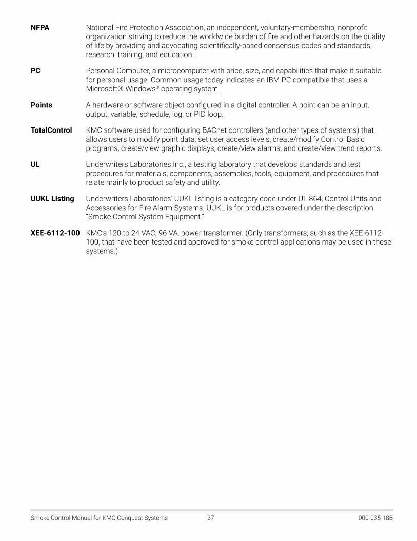
Smoke Control Manual for KMC Conquest Systems 37 000-035-18B
NFPA National Fire Protection Association, an independent, voluntary-membership, nonprofit organization striving to reduce the worldwide burden of fire and other hazards on the quality of life by providing and advocating scientifically-based consensus codes and standards, research, training, and education.
PC Personal Computer, a microcomputer with price, size, and capabilities that make it suitable for personal usage. Common usage today indicates an IBM PC compatible that uses a Microsoft® Windows® operating system.
Points A hardware or software object configured in a digital controller. A point can be an input, output, variable, schedule, log, or PID loop.
TotalControl KMC software used for configuring BACnet controllers (and other types of systems) that allows users to modify point data, set user access levels, create/modify Control Basic programs, create/view graphic displays, create/view alarms, and create/view trend reports.
UL Underwriters Laboratories Inc., a testing laboratory that develops standards and test procedures for materials, components, assemblies, tools, equipment, and procedures that relate mainly to product safety and utility.
UUKL Listing Underwriters Laboratories’ UUKL listing is a category code under UL 864, Control Units and Accessories for Fire Alarm Systems. UUKL is for products covered under the description “Smoke Control System Equipment.”
XEE-6112-100 KMC’s 120 to 24 VAC, 96 VA, power transformer. (Only transformers, such as the XEE-6112-100, that have been tested and approved for smoke control applications may be used in these systems.)

Smoke Control Manual for KMC Conquest Systems 38 000-035-18B
Appendixes
Device Electrical RatingsBAC-5900 Series General Purpose ControllerInputs, Universal (8 on Terminal Blocks)
Universal inputs Configurable as analog, binary, or accumulator objectsTermination 1K and 10K ohm sensors, 0–12 VDC, or 0–20 mA (without need for an external resistor)Resolution 16-bit analog-to-digital conversionProtection Overvoltage protection (24 VAC, continuous)Wire size 12–24 AWG, copper, in removable screw terminal blocks
Input, Dedicated Room Sensor Port
Connector Modular connector for STE-9xx1 series digital wall sensors or STE-6010/6014/6017 analog tempera-ture sensors
Cable Uses standard Ethernet patch cable up to 150 feet (45 meters)
Outputs, Universal (8 on Terminal Blocks)
Universal outputs Configurable as an analog (0 to 12 VDC) or binary object (0 or 12 VDC, on/off); alternately, an output override board is installed for devices that cannot be powered from a standard universal output
Power/protection Each short-circuit protected universal output capable of driving up to 100 mA (at 0–12 VDC) or 300 mA total for all outputs
Resolution 12-bit digital-to-analog conversionWire size 12–24 AWG, copper, in removable screw terminal blocks
Power
Supply voltage 24 VAC (60 Hz); –15%, +20%; Class 2 only; non-supervised (all circuits, including supply voltage, are power limited circuits)
Required power 14 VA, plus external loadsWire size 12–24 AWG, copper, in a removable screw terminal block
BAC-9300 Series Unitary ControllerInputs, Universal (6 on Terminal Blocks)
Universal inputs Configurable as analog, binary, or accumulator objectsTermination 1K and 10K ohm sensors, 0–12 VDC, or 0–20 mA (without need for an external resistor)Resolution 16-bit analog-to-digital conversionProtection Overvoltage protection (24 VAC, continuous)Wire size 12–24 AWG, copper, in removable screw terminal blocks
Input, Dedicated Room Sensor Port
Connector Modular connector for STE-9xx1 series digital wall sensors or STE-6010/6014/6017 analog tempera-ture sensors
Cable Uses standard Ethernet patch cable up to 150 feet (45 meters)

Smoke Control Manual for KMC Conquest Systems 39 000-035-18B
Outputs, Universal (4 on Terminal Blocks)
Universal outputs Configurable as an analog (0 to 12 VDC) or binary object (0 or 12 VDC, on/off)Power/protection Each short-circuit protected universal output capable of driving up to 100 mA (at 0–12 VDC) or 100
mA total for all outputsResolution 12-bit digital-to-analog conversionWire size 12–24 AWG, copper, in removable screw terminal blocks
Outputs, Triac (6 Binary)
Triac outputs Optically isolated zero-crossing triac output configured as a binary objectPower Maximum switching 24 VAC at 1.0 A for each output; maximum total for controller is 3.0 AWire size 12–24 AWG, copper, in removable screw terminal blocks
Power
Supply voltage 24 VAC (60 Hz); –15%, +20%; Class 2 only; non-supervised (all circuits, including supply voltage, are power limited circuits)
Required power 12 VA, plus external loadsWire size 12–24 AWG, copper, in a removable screw terminal block
CAN-5901 I/O Expansion ModuleInputs, Universal (8 on Terminal Blocks)
Universal inputs Configurable as analog, binary, or accumulator objectsTermination 1K and 10K ohm sensors, 0–12 VDC, or 0–20 mA (without need for an external resistor)Resolution 16-bit analog-to-digital conversionProtection Overvoltage protection (24 VAC, continuous)Wire size 12–24 AWG, copper, in removable screw terminal blocks
Outputs, Universal
Universal outputs Configurable as an analog (0 to 12 VDC) or binary object (0 or 12 VDC, on/off); alternately, an output override board is installed for devices that cannot be powered from a standard universal output (8 on CAN-5901)
Power/protection Each short-circuit protected universal output capable of driving up to 100 mA (at 0–12 VDC) or 300 mA total for all outputs
Resolution 12-bit digital-to-analog conversionWire size 12–24 AWG, copper, in removable screw terminal blocks
Power
Supply voltage 24 VAC (60 Hz); –15%, +20%; Class 2 only; non-supervised (all circuits, including supply voltage, are power limited circuits)
Required power 14 VA, plus external loadsWire size 12–24 AWG, copper, in a removable screw terminal block

Smoke Control Manual for KMC Conquest Systems 40 000-035-18B
BAC-5051E BACnet RouterAC supply voltage 24 VAC (–15%, +20%), 60 Hz, Class 2 only; non-supervised All circuits, including supply voltage, are
power limited circuits.Required power 12 VA
HPO-6701/6704 Output Override BoardsHPO-6701 Triac output w/ zero-cross switching (AC only)HPO-6704 4–20 mA DC (@ 10 VDC) current loop output with an adjustable override potentiometer for “Hand”
output
KMD-5567 Suppressor Module and Terminal ConnectorRequired for EIA-485 terminals of controllers in MS/TP controllers in smoke control applications.Peak Surge Current 8 x 20 µs 10 kA, 10 x 700 µs 500 A per line
XEE-6112-100 TransformerPrimary 120 VAC, 60 Hz, 96 VA
Secondary 24 VAC
NOTE: Use only 24 VAC @ 60 Hz to power KMC Conquest controllers for smoke control applications.

Smoke Control Manual for KMC Conquest Systems 41 000-035-18B
Air Handler Smoke Control ModesThe diagrams below define the equipment configuration for the various modes used in the FSCS in the example programming.
EA
OA
EA
OA
EA
OA
EA
OA
KEY
◆ EA—Exhaust air
◆ OA—Outside air
◆ 0%—Fully closed
◆ 100%—Fully open
◆ MOD—Modulating, controlling based on temperature or air flow (any position is acceptable)
◆ ON—Fan is running and moving air
◆ OFF—Fan is not running
EA
OA
AUTOMATIC
OFF
EXHAUST
PRESSURIZE
PURGE
EA

Smoke Control Manual for KMC Conquest Systems 42 000-035-18B
Installation Instructions for FSCS EnclosuresFSCS enclosures should be securely mounted to the wall. The wall should be structurally capable of supporting the weight of the enclosure. (See also Power Wiring on page 19 and Enclosure on page 19.)
All wire entries to the enclosure must be in conduit. Typical conduit entries should be located on the centerline of the sides, top, or bottom of the enclosure. Actual location of conduit entry points varies per project and reasonable variations are allowed using the following guidelines.
◆ Do not locate conduits within 1½ inches of any corner of the enclosure.
◆ Do not locate conduits behind the electronics subplate mounted in the enclosure. (See attached sketch.)
◆ Do not locate conduits where they will interfere or damage control panel electronics.
◆ Use separate conduits for power-limited and non-power-limited circuits.
◆ Locate the power input conduit near the power supply input terminals. Power supply locations vary per project.
◆ Locate conduits for data lines and optional remote fire system inputs near their associated input terminals. Locations of terminals for data lines and remote inputs vary per project.
◆ FSCS enclosures are provided from the manufacturer with transient suppressors for all external inputs including signal and power lines per the design specification of your particular job. Do NOT, under any circumstances, connect additional external circuits that are not part of the original specification to your FSCS without first consulting the factory.
1.5
SUBPLATE
NO CONDUIT WITHIN 1.5 INCHES OF A
CORNER OR BEHIND A SUBPLATE
1.5
1.5
1.51.5
1.5
1.5
1.5

Smoke Control Manual for KMC Conquest Systems 43 000-035-18B
Sample FSCS and Field Panel DrawingsThe following four pages contain sample drawings for a small FSCS and field panels. The example uses a four-story building with an air handler for each floor. There is also a stairwell fan for stair pressurization. A switch at each level allows the firefighting personnel to set each floor to the appropriate mode to isolate the smoke in the event of a fire.
In this example, all fans supply less than 2000 cfm. If fans have a capacity greater than 2000 cfm, the status of each fan must be indicated on the panel. This status must be sensed with a differential pressure sensor across the fan.
Every smoke control system is custom designed for each application. Contact KMC Controls for assistance with your design.
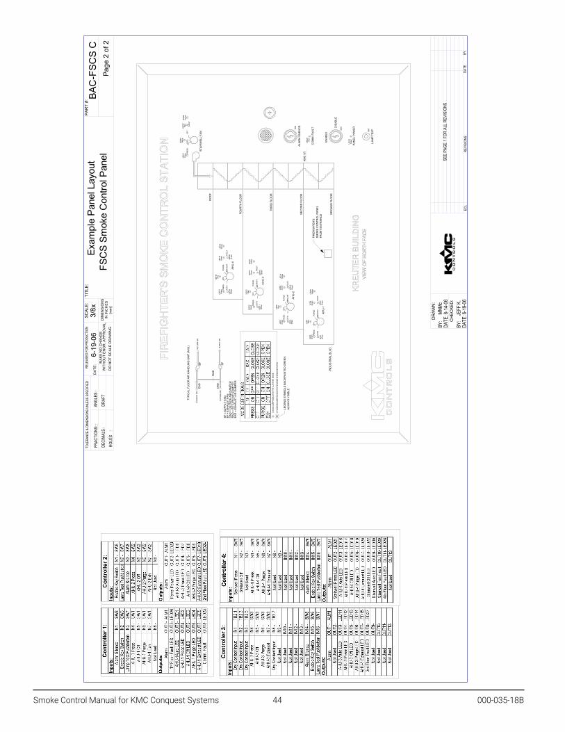
Smoke Control Manual for KMC Conquest Systems 44 000-035-18B
PRES
S.
A
UTO
OFF
FA
ULT
STAI
RW
ELL
FAN
RO
OF
FOU
RTH
FLO
OR
THIR
D F
LOO
R
SEC
ON
D F
LOO
R
GR
OU
ND
FLO
OR
IND
UST
RIA
L BL
VD.
KMC
ST.
TYPI
CAL
FLO
OR
AIR
HAN
DLI
NG
UN
IT (A
HU
)
EAD
OAD
RAD
EF SF
LEG
END
SYM
BOLS
BAC
KPAI
NTE
D G
REE
NAL
WAY
S VI
SIBL
E
EXH
AUST
AIR
OU
TSID
E AI
R
RET
UR
N A
IR
SUPP
LY A
IR
A SO
LID
LAM
P IN
DIC
ATES
TH
E C
UR
REN
T M
OD
E.
A FL
ASH
ING
LAM
P IN
DIC
ATES
TH
E M
OD
E IS
BEI
NG
INIT
IATE
D.
FIR
EFIG
HTE
R'S
SMO
KE C
ON
TRO
L PA
NEL
FRO
NT
ENTR
ANC
E
ALAR
M S
ILEN
CE
CO
MM
. FAU
LT
ENAB
LE
DIS
ABLE
PAN
EL P
OW
ER
LAM
P TE
ST
PRES
S.
OFF
PU
RG
E
AUTO
EXH
AUST
FAU
LT
AHU
-4
AHU
-3
AHU
-2
AHU
-1
PRES
S.
OFF
PU
RG
E
AUTO
EXH
AUST
FAU
LT
PRES
S.
OFF
PU
RG
E
AUTO
EXH
AUST
FAU
LT
PRES
S.
OFF
PU
RG
E
AUTO
EXH
AUST
FAU
LT
SF =
SU
PPLY
FAN
EF =
EXH
AUST
FAN
OAD
= O
UTS
IDE
AIR
DAM
PER
RAD
= R
ETU
RN
AIR
DAM
PER
EAD
= E
XHAU
ST A
IR D
AMPE
R
LED
29Ye
llow
LED
28Ye
llow
LED
27Ye
llow
LED
24Ye
llow
LED
26Ye
llow
LED
3R
ed
LED
8R
ed
LED
13R
ed
LED
18R
ed
LED
21G
reen
LED
30W
hite
LED
22R
ed
LED
16W
hite
LED
11W
hite
LED
6W
hite
LED
1W
hite
LED
2G
reen
LED
4G
reen
LED
5G
reen
LED
7G
reen
LED
9G
reen
LED
10G
reen
LED
12G
reen
LED
14G
reen
LED
15G
reen
LED
17G
reen
LED
19G
reen
LED
20G
reen
LED
25R
ed
LED
23G
reen
SW6
SW7SW
8
ANGL
ES6-
19-0
63/
8xEx
ampl
e Pa
nel L
ayou
t
FSC
S Sm
oke
Con
trol P
anel
Page
2 o
f 2
BAC
-FSC
S C
BY:
JEF
F K.
DATE
: 6-1
9-06
CH
ECKE
D:
BY:
MNM
cDA
TE: 6
-14-
06
DR
AWN
:
SEE
PAG
E 1
FOR
ALL
REVI
SION
S
PAR
T #:
DRAF
THO
LES
DECI
MAL
SFR
ACTI
ONS:
YBETAD
SNOISIVERLCE
DO
NO
T S
CA
LE D
RA
WIN
G
DA
TE:
TOLE
RANC
E &
DIME
NSIO
NS U
NLES
S SP
ECIF
IED
RELE
ASED
FOR
PRO
DUCT
ION
MA
KE
NO
CH
AN
GE
WIT
HO
UT
EN
GR
. AP
PR
OV
AL
DIM
EN
SIO
NS
IN IN
CH
ES
[mm
]
SCAL
E:TI
TLE:

Smoke Control Manual for KMC Conquest Systems 45 000-035-18B
GN
D
N.C.
TB3
GND
120V
AC60
Hz 1A
M.O.
V.No
te 2
M.O.
V.No
te 2
Inputs
from
FAC
PFir
e Alar
m Co
ntrol
Pane
lse
e Note
7
CNTR
L-1
CNTR
L-2
Not P
ower
Lim
ited
TB2
T1B1
TB1
EIO-4
EIO-3
EIO-1
EIO-2
Powe
r Lim
ited
Powe
r Lim
ited
Not P
ower
Lim
ited
120V
AC, 6
0Hz,
2.0A
Not S
uper
vised H N G
18AW
G ca
bletw
isted
, shie
lded
Note
5
Prev
ious D
evice
Next
Devic
e;12
4 Dev
ices m
ax.
on S
ubNe
twor
k
NO
TES:
1-Te
rmin
al B
lock
s; m
axim
um 2
con
duct
ors
per t
erm
inal
scr
ew.
2-Va
risto
rs in
stal
led
on 6
" 18A
WG
lead
s, c
ondu
ctor
s co
vere
d
with
hea
t-shr
ink
tubi
ng.
3-In
puts
: Ref
er to
Con
trolle
r Spe
cific
atio
ns.
4-O
utpu
ts: R
efer
to C
ontro
ller S
peci
ficat
ions
.5-
Com
mun
icat
ions
: 18A
WG
shi
elde
d pa
ir, s
uper
vise
d, p
ower
lim
ited,
m
ax. l
ine
resi
stan
ce: 1
47 o
hms
.27u
F. R
S-48
5, 5
V P-
P, 2
00m
A m
ax. s
hort
circ
uit.
C
omm
unic
atio
ns s
hiel
d m
ust b
e co
ntin
uous
, tie
d to
geth
er &
gro
unde
d at
onl
y 1
poin
t in
the
netw
ork.
6-Fi
re a
larm
inpu
ts fr
om fi
re a
larm
con
trol p
anel
(FAC
P) m
ust b
e lis
ted
for f
ire p
rote
ctiv
e si
gnal
ing
use,
ra
ted
dry
cont
act o
r 5VD
C m
ax.,
0.5m
A m
ax.,
pow
er li
mite
d, n
ot s
uper
vise
d.
ECN
BAC
CQ
FSC
SC
onqu
est P
anel
Lay
out
Smok
e C
ontro
l Pan
el E
xam
ple
5/16
x2-
20-1
9A
BY: J
EMDA
TE: 2
-20-
19
BY: J
eff K
DATE
: 2-2
0-19
H
E
D
B
C
A
INIT
IAL P
RINT
REL
EASE
2-2
0-19
J
EM
F
G
ECL:
FRAC
TION
S:
DECI
MALS
HO
LES
DR
AFT
PAR
T #:
Page
1 o
f 2
ANGL
ES
TITL
E:SC
ALE:
DIM
ENSI
ON
SIN
INC
HES
[mm
]
MAK
E N
O C
HAN
GE
WIT
HO
UT
ENG
R. A
PPR
OVA
L
RELE
ASED
FOR
PRO
DUCT
ION
TOLE
RANC
E &
DIME
NSIO
NS U
NLES
S SP
ECIF
IED
DAT
E: DO
NO
T SC
ALE
DR
AWIN
G
ECL
R
EVIS
IONS
DAT
E
B
Y
DR
AWN
:
CH
ECKE
D:

Smoke Control Manual for KMC Conquest Systems 46 000-035-18B
2" Min
.
2" M
in.
(L)
(N)
Pow
erLi
mite
d
Not
Pow
erLi
mite
d
Pow
erLi
mite
d
Bran
ch C
ircui
t12
0VAC
15A,
60H
z
Bra
nch
Circ
uit W
iring
next B
next A
TB1
CN
TRL-
1
T1
Addi
tiona
l Con
trolle
rs a
s ne
eded
NO
TES:
1-Te
rmin
al B
lock
s; m
axim
um 2
con
duct
ors
per t
erm
inal
scr
ew.
2-In
puts
: Ref
er to
Con
trolle
r Spe
cific
atio
ns.
3-O
utpu
ts: R
efer
to C
ontro
ller S
peci
ficat
ions
.4-
Com
mun
icat
ions
: 18A
WG
shi
elde
d pa
ir, s
uper
vise
d, p
ower
lim
ited,
max
.
line
resi
stan
ce: 1
47 o
hms
.27u
F. R
S-48
5, 5
V P-
P, 2
00m
A m
ax.s
hort
circ
uit.
C
omm
unic
atio
ns s
hiel
d m
ust b
e co
ntin
uous
, tie
d to
geth
er
& gr
ound
ed a
t onl
y 1
poin
t in
the
netw
ork.
5-M
inim
um e
nclo
sure
siz
e: 1
6" w
idth
x 1
8" h
eigh
t x 6
" dep
th.
INST
ALLA
TIO
N N
OTE
S (W
iring
):Pr
ovid
e 15
Am
p Br
anch
Circ
uit:
Cla
ss 1
Wiri
ng =
Not
Pow
er L
imite
d.12
0VAC
, 60
Hz
60C
, Cu
Wire
14
AWG
Pane
l Dis
conn
ect P
rovi
ded
by In
stal
ler.
Cla
ss 2
Wiri
ng =
Pow
er L
imite
d
NO
TE:
Pow
er L
imite
d &
Non
-Pow
er L
imite
d w
iring
mus
t be
perm
anen
tly s
epar
ated
by
2 in
ches
(min
imum
) & s
hall
be a
ccom
plis
hed
by c
lam
ping
, rou
ting,
or e
quiv
alen
t mea
ns.
ECN
BAC
CQ
FPW
1C
onqu
est B
ACne
t Fie
ld P
anel
Wiri
ng E
xam
ple
#15/
16x
2-20
-19
A
BY: J
EMDA
TE: 2
-20-
19
BY: J
eff K
DATE
: 2-2
0-19
H
E
D
B
C
A
INIT
IAL P
RINT
REL
EASE
2-2
0-19
J
EM
F
G
ECL:
FRAC
TION
S:
DECI
MALS
HO
LES
DR
AFT
PAR
T #:
Page
1 o
f 1
ANGL
ES
TITL
E:SC
ALE:
DIM
ENSI
ON
SIN
INC
HES
[mm
]
MAK
E N
O C
HAN
GE
WIT
HO
UT
ENG
R. A
PPR
OVA
L
RELE
ASED
FOR
PRO
DUCT
ION
TOLE
RANC
E &
DIME
NSIO
NS U
NLES
S SP
ECIF
IED
DAT
E: DO
NO
T SC
ALE
DR
AWIN
G
ECL
R
EVIS
IONS
DAT
E
B
Y
DR
AWN
:
CH
ECKE
D:
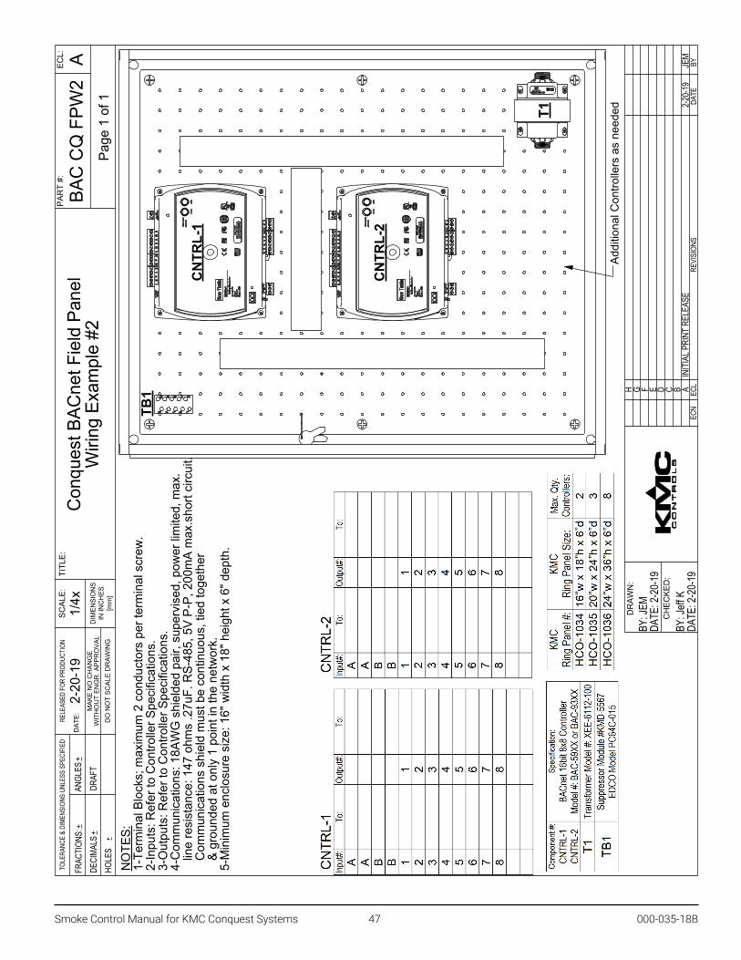
Smoke Control Manual for KMC Conquest Systems 47 000-035-18B
CNTR
L-1
T1
TB1
Addi
tiona
l Con
trolle
rs a
s ne
eded
CNTR
L-2
NO
TES:
1-Te
rmin
al B
lock
s; m
axim
um 2
con
duct
ors
per t
erm
inal
scr
ew.
2-In
puts
: Ref
er to
Con
trolle
r Spe
cific
atio
ns.
3-O
utpu
ts: R
efer
to C
ontro
ller S
peci
ficat
ions
.4-
Com
mun
icat
ions
: 18A
WG
shi
elde
d pa
ir, s
uper
vise
d, p
ower
lim
ited,
max
.
line
resi
stan
ce: 1
47 o
hms
.27u
F. R
S-48
5, 5
V P-
P, 2
00m
A m
ax.s
hort
circ
uit.
C
omm
unic
atio
ns s
hiel
d m
ust b
e co
ntin
uous
, tie
d to
geth
er
& gr
ound
ed a
t onl
y 1
poin
t in
the
netw
ork.
5-M
inim
um e
nclo
sure
siz
e: 1
6" w
idth
x 1
8" h
eigh
t x 6
" dep
th.
ECN
Con
ques
t BAC
net F
ield
Pan
elW
iring
Exa
mpl
e #2
BAC
CQ
FPW
2AEC
L:
FRAC
TION
S:
DECI
MALS
HO
LES
DR
AFT
PAR
T #:
Page
1 o
f 1
1/4x
2-20
-19
ANGL
ES
TITL
E:SC
ALE:
DIM
ENSI
ON
SIN
INC
HES
[mm
]
MAK
E N
O C
HAN
GE
WIT
HO
UT
ENG
R. A
PPR
OVA
L
RELE
ASED
FOR
PRO
DUCT
ION
TOLE
RANC
E &
DIME
NSIO
NS U
NLES
S SP
ECIF
IED
DAT
E: DO
NO
T SC
ALE
DR
AWIN
G
H
BY: J
eff K
DATE
: 2-2
0-19
CH
ECKE
D:
BY: J
EMDA
TE: 2
-20-
19
DR
AWN
:
E D BC A
INIT
IAL P
RINT
REL
EASE
2-2
0-19
J
EM
FG ECL
R
EVIS
IONS
DAT
E
B
Y

Smoke Control Manual for KMC Conquest Systems 48 000-035-18B© 2020 KMC Controls, Inc. Specifications and design subject to change without notice 000-035-18B
CNTR
L-1
T1
TB1
Addi
tiona
l Con
trolle
rs a
s ne
eded
CNTR
L-2
GND
NO
TES:
1-Te
rmin
al B
lock
s; m
axim
um 2
con
duct
ors
per t
erm
inal
scr
ew.
2-In
puts
: Ref
er to
Con
trolle
r Spe
cific
atio
ns.
3-O
utpu
ts: R
efer
to C
ontro
ller S
peci
ficat
ions
.4-
Com
mun
icat
ions
: Use
CAT
5 C
able
300
' Max
.5-
Min
imum
enc
losu
re s
ize:
16"
wid
th x
18"
hei
ght x
6" d
epth
.
ECN
Con
ques
t BAC
net F
ield
Pan
elW
iring
Exa
mpl
e #3
BAC
CQ
FPW
3AEC
L:
FRAC
TION
S:
DECI
MALS
HO
LES
DR
AFT
PAR
T #:
Page
1 o
f 1
1/4x
2-20
-19
ANGL
ES
TITL
E:SC
ALE:
DIM
ENSI
ON
SIN
INC
HES
[mm
]
MAK
E N
O C
HAN
GE
WIT
HO
UT
ENG
R. A
PPR
OVA
L
RELE
ASED
FOR
PRO
DUCT
ION
TOLE
RANC
E &
DIME
NSIO
NS U
NLES
S SP
ECIF
IED
DAT
E: DO
NO
T SC
ALE
DR
AWIN
G
H
BY: J
eff K
DATE
: 2-2
0-19
CH
ECKE
D:
BY: J
EMDA
TE: 2
-20-
19
DR
AWN
:
E D BC A
INIT
IAL P
RINT
REL
EASE
2-2
0-19
J
EM
FG ECL
R
EVIS
IONS
DAT
E
B
Y