Sixteen-Point Digital Compass
16
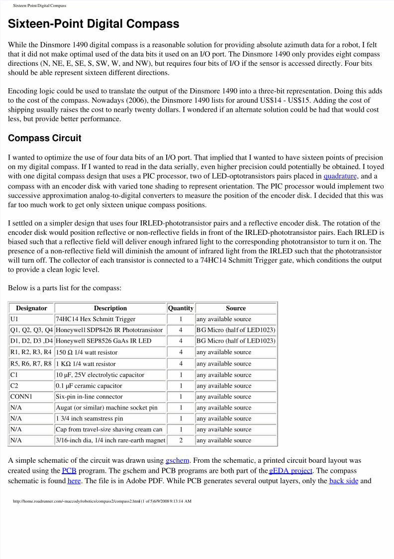
Sixteen-Point Digital Compass Sixteen-Point Digital Compass While the Dinsmore 1490 digital compass is a reasonable solution for providing absolute azimuth data for a robot, I felt that it did not make optimal used of the data bits it used on an I/O port. The Dinsmore 1490 only provides eight compass directions (N, NE, E, SE, S, SW, W, and NW), but requires four bits of I/O if the sensor is accessed directly. Four bits should be able represent sixteen different directions. Encoding logic could be used to translate the output of the Dinsmore 1490 into a three-bit representation. Doing this adds to the cost of the compass. Nowadays (2006), the Dinsmore 1490 lists for around US$14 - US$15. Adding the cost of shipping usually raises the cost to nearly twenty dollars. I wondered if an alternate solution could be had that would cost less, but provide better performance. Compass Circuit I wanted to optimize the use of four data bits of an I/O port. That implied that I wanted to have sixteen points of precision on my digital compass. If I wanted to read in the data serially, even higher precision could potentially be obtained. I toyed with one digital compass design that uses a PIC processor, two of LED-optotransistors pairs placed in quadrature, and a compass with an encoder disk with varied tone shading to represent orientation. The PIC processor would implement two successive approximation analog-to-digital converters to measure the position of the encoder disk. I decided that this was far too much work to get only sixteen unique compass positions. I settled on a simpler design that uses four IRLED-phototransistor pairs and a reflective encoder disk. The rotation of the encoder disk would position reflective or non-reflective fields in front of the IRLED-phototransistor pairs. Each IRLED is biased such that a reflective field will deliver enough infrared light to the corresponding phototransistor to turn it on. The presence of a non-reflective field will diminish the amount of infrared light from the IRLED such that the phototransistor will turn off. The collector of each transistor is connected to a 74HC14 Schmitt Trigger gate, which conditions the output to provide a clean logic level. Below is a parts list for the compass: Designator Description Quantity Source U1 74HC14 Hex Schmitt Trigger 1 any available source Q1, Q2, Q3, Q4 Honeywell SDP8426 I R Phototransistor 4 BG Micro (half of LED1023) D1, D2, D3 ,D4Honeywell SEP8526 GaAs IR LED 4 BG Micro (half of LED1023) R1, R2, R3, R4 150 Ω 1/4 watt resistor 4 any available source R5, R6, R7, R8 1 KΩ 1/4 watt resistor 4 any available source C1 10 µF, 25V electrolytic capacitor 1 any available source C2 0.1 µF ceramic capacitor 1 any available source CONN1 Six-pin in-line connector 1 any available source N/A Augat (or similar) machine socket pin 1 any available source N/A 1 3/4 inch seamstress pin 1 any available source N/A Cap from travel-size shaving cream can 1 any available source N/A 3/16-inch dia, 1/4 inch rare-earth magnet 2 any available source A simple schematic of the circuit was drawn using gschem. From the schematic, a printed circuit board layout was created using the PCB program. The gschem and PCB programs are both part of the gEDA project . The compass schematic is found here. The file is in Adobe PDF. While PCB generates several output layers, only the back side and http://home.roadrunner.com/ ~maccody/robotics/compass2/compass2.html (1 of 5)6/9/2008 9:13:14 AM
-
Upload
duncan0420 -
Category
Documents
-
view
224 -
download
0
Transcript of Sixteen-Point Digital Compass
8/13/2019 Sixteen-Point Digital Compass
http://slidepdf.com/reader/full/sixteen-point-digital-compass 1/16
ixteen-Point Digital Compass
ixteen-Point Digital Compass
hile the Dinsmore 1490 digital compass is a reasonable solution for providing absolute azimuth data for a robot, I f
at it did not make optimal used of the data bits it used on an I/O port. The Dinsmore 1490 only provides eight comp
ections (N, NE, E, SE, S, SW, W, and NW), but requires four bits of I/O if the sensor is accessed directly. Four bit
ould be able represent sixteen different directions.
coding logic could be used to translate the output of the Dinsmore 1490 into a three-bit representation. Doing this a
the cost of the compass. Nowadays (2006), the Dinsmore 1490 lists for around US$14 - US$15. Adding the cost ofipping usually raises the cost to nearly twenty dollars. I wondered if an alternate solution could be had that would c
s, but provide better performance.
ompass Circuit
wanted to optimize the use of four data bits of an I/O port. That implied that I wanted to have sixteen points of preci
my digital compass. If I wanted to read in the data serially, even higher precision could potentially be obtained. I to
th one digital compass design that uses a PIC processor, two of LED-optotransistors pairs placed in quadrature, an
mpass with an encoder disk with varied tone shading to represent orientation. The PIC processor would implement
ccessive approximation analog-to-digital converters to measure the position of the encoder disk. I decided that thistoo much work to get only sixteen unique compass positions.
ettled on a simpler design that uses four IRLED-phototransistor pairs and a reflective encoder disk. The rotation of
coder disk would position reflective or non-reflective fields in front of the IRLED-phototransistor pairs. Each IRLE
ased such that a reflective field will deliver enough infrared light to the corresponding phototransistor to turn it on.
esence of a non-reflective field will diminish the amount of infrared light from the IRLED such that the phototransi
ll turn off. The collector of each transistor is connected to a 74HC14 Schmitt Trigger gate, which conditions the ou
provide a clean logic level.
low is a parts list for the compass:
Designator Description Quantity Source
1 74HC14 Hex Schmitt Trigger 1 any available source
1, Q2, Q3, Q4 Honeywell SDP8426 IR Phototransistor 4 BG Micro (half of LED1023)
1, D2, D3 ,D4 Honeywell SEP8526 GaAs IR LED 4 BG Micro (half of LED1023)
1, R2, R3, R4 150 Ω 1/4 watt resistor 4 any available source
5, R6, R7, R8 1 KΩ 1/4 watt resistor 4 any available source
1 10 µF, 25V electrolytic capacitor 1 any available source
2 0.1 µF ceramic capacitor 1 any available source
ONN1 Six-pin in-line connector 1 any available source
/A Augat (or similar) machine socket pin 1 any available source
/A 1 3/4 inch seamstress pin 1 any available source
/A Cap from travel-size shaving cream can 1 any available source
/A 3/16-inch dia, 1/4 inch rare-earth magnet 2 any available source
simple schematic of the circuit was drawn using gschem. From the schematic, a printed circuit board layout was
eated using the PCB program. The gschem and PCB programs are both part of the gEDA project. The compass
hematic is found here. The file is in Adobe PDF. While PCB generates several output layers, only the back side and
tp://home.roadrunner.com/~maccody/robotics/compass2/compass2.html (1 of 5)6/9/2008 9:13:14 AM
8/13/2019 Sixteen-Point Digital Compass
http://slidepdf.com/reader/full/sixteen-point-digital-compass 2/16
ixteen-Point Digital Compass
ont silk layers are used for the printed circuit board and the component layout silk screen. Note that the front silk lay
e has been manipulated to form a mirror image file. This was done so that laser toner transfer method could be used
eate the component layout pattern as well as the printed circuit positive mask. These files are also in Adobe PDF.
ncoder Disk
mentioned earlier, an encoder disk is used to sense the orientation of the compass. The encoder disk rotates above
LED-phototransistor pairs. The compass magnet is attached to the encoder disk such that the rotational offset of the
coder disk indicates absolute azimuth of the compass mechanism.
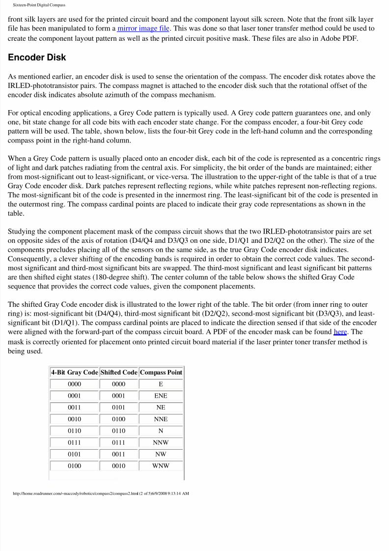
r optical encoding applications, a Grey Code pattern is typically used. A Grey code pattern guarantees one, and onl
e, bit state change for all code bits with each encoder state change. For the compass encoder, a four-bit Grey code
ttern will be used. The table, shown below, lists the four-bit Grey code in the left-hand column and the correspondi
mpass point in the right-hand column.
hen a Grey Code pattern is usually placed onto an encoder disk, each bit of the code is represented as a concentric
light and dark patches radiating from the central axis. For simplicity, the bit order of the bands are maintained; eith
om most-significant out to least-significant, or vice-versa. The illustration to the upper-right of the table is that of a
ay Code encoder disk. Dark patches represent reflecting regions, while white patches represent non-reflecting regi
e most-significant bit of the code is presented in the innermost ring. The least-significant bit of the code is presentee outermost ring. The compass cardinal points are placed to indicate their gray code representations as shown in the
ble.
udying the component placement mask of the compass circuit shows that the two IRLED-phototransistor pairs are s
opposite sides of the axis of rotation (D4/Q4 and D3/Q3 on one side, D1/Q1 and D2/Q2 on the other). The size of
mponents precludes placing all of the sensors on the same side, as the true Gray Code encoder disk indicates.
onsequently, a clever shifting of the encoding bands is required in order to obtain the correct code values. The secon
ost significant and third-most significant bits are swapped. The third-most significant and least significant bit patter
e then shifted eight states (180-degree shift). The center column of the table below shows the shifted Gray Code
quence that provides the correct code values, given the component placements.
e shifted Gray Code encoder disk is illustrated to the lower right of the table. The bit order (from inner ring to oute
g) is: most-significant bit (D4/Q4), third-most significant bit (D2/Q2), second-most significant bit (D3/Q3), and le
gnificant bit (D1/Q1). The compass cardinal points are placed to indicate the direction sensed if that side of the enco
ere aligned with the forward-part of the compass circuit board. A PDF of the encoder mask can be found here. The
ask is correctly oriented for placement onto printed circuit board material if the laser printer toner transfer method i
ing used.
4-Bit Gray Code Shifted Code Compass Point
0000 0000 E0001 0001 ENE
0011 0101 NE
0010 0100 NNE
0110 0110 N
0111 0111 NNW
0101 0011 NW
0100 0010 WNW
tp://home.roadrunner.com/~maccody/robotics/compass2/compass2.html (2 of 5)6/9/2008 9:13:14 AM
8/13/2019 Sixteen-Point Digital Compass
http://slidepdf.com/reader/full/sixteen-point-digital-compass 3/16
ixteen-Point Digital Compass
1100 1010 W
1101 1011 WSW
1111 1111 SW
1110 1110 SSW
1010 1100 S
1011 1101 SSE
1001 1001 SE
1000 1000 ESE
The pattern for a true Gray Code encoder disk.
The pattern for the shifted Gray Code encoder disk.
ompass Assembly and Testing
e compass circuit board is easily fabricated using the laser printer
ner transfer method and the circuit and component layout masks
scribed above. The assembly of the compass circuit is
aightforward, as there are few components to place on the circuit
ard.
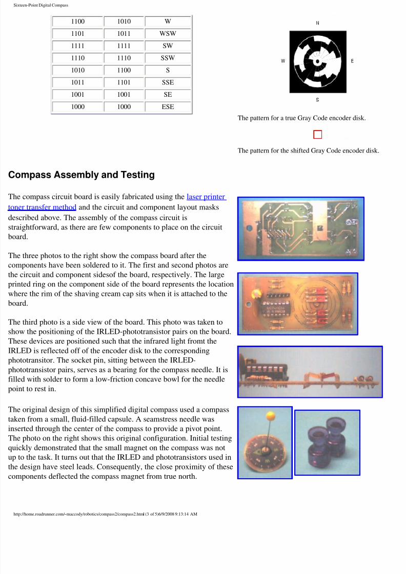
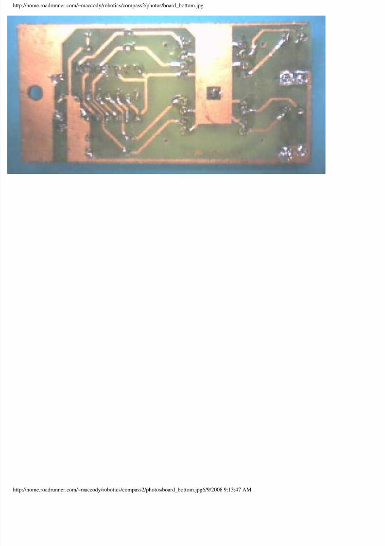
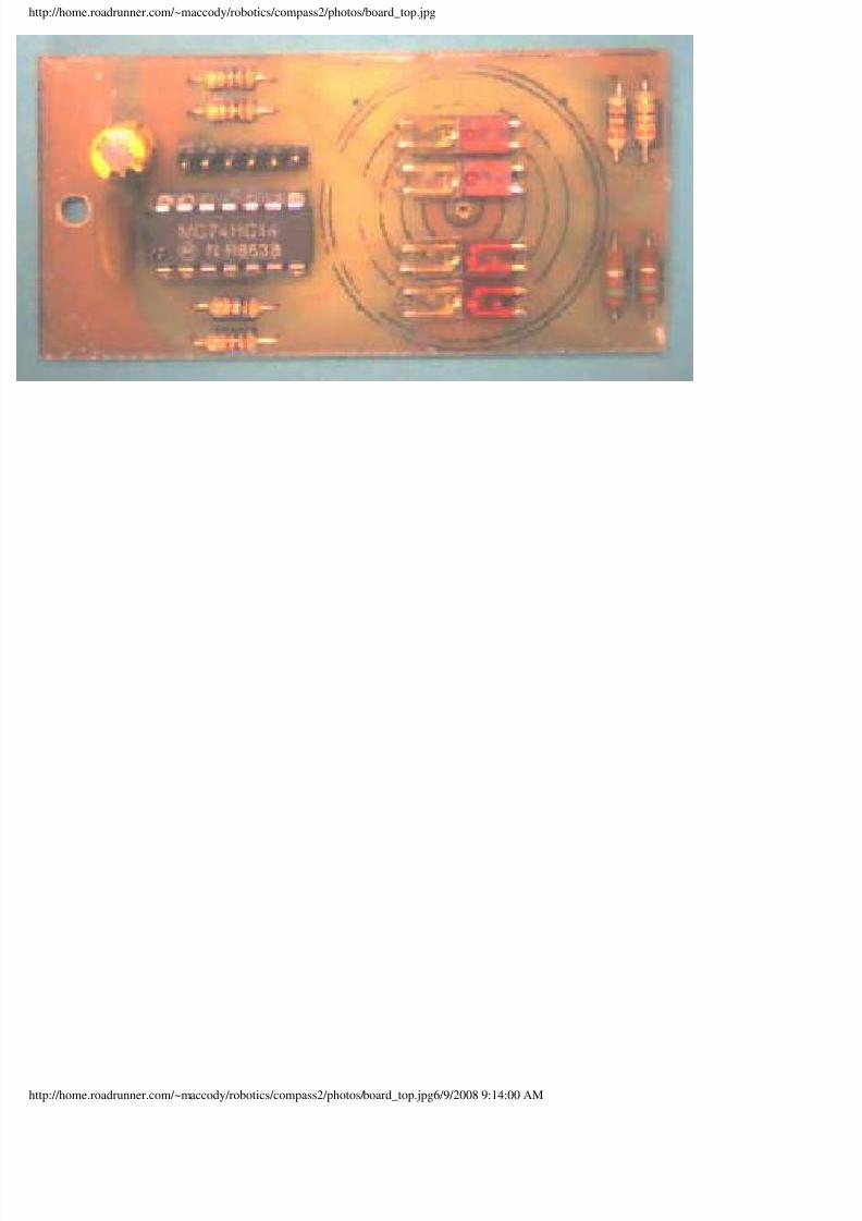
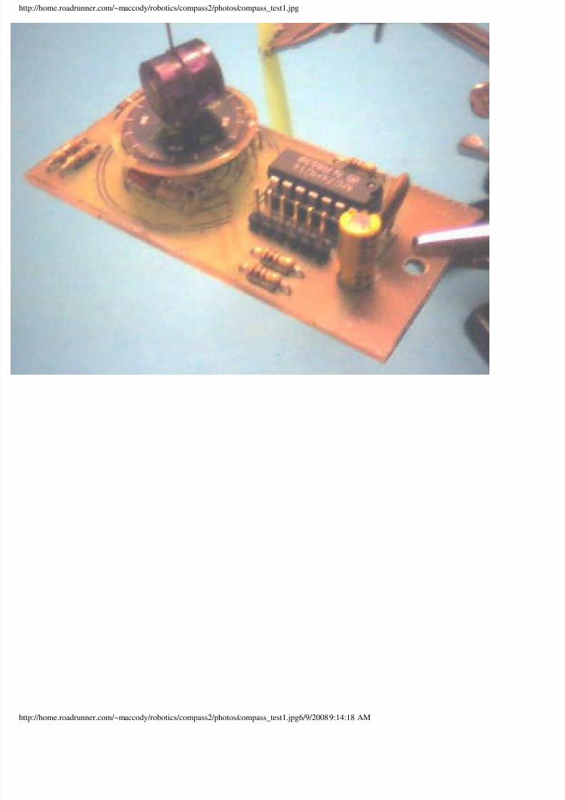
e three photos to the right show the compass board after the
mponents have been soldered to it. The first and second photos are
e circuit and component sidesof the board, respectively. The large
nted ring on the component side of the board represents the location
here the rim of the shaving cream cap sits when it is attached to the
ard.
e third photo is a side view of the board. This photo was taken to
ow the positioning of the IRLED-phototransistor pairs on the board.
ese devices are positioned such that the infrared light fromt the
LED is reflected off of the encoder disk to the corresponding
ototransitor. The socket pin, sitting between the IRLED-
ototransistor pairs, serves as a bearing for the compass needle. It is
led with solder to form a low-friction concave bowl for the needle
int to rest in.
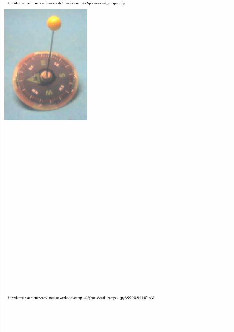
e original design of this simplified digital compass used a compass
ken from a small, fluid-filled capsule. A seamstress needle was
erted through the center of the compass to provide a pivot point.
e photo on the right shows this original configuration. Initial testing
ickly demonstrated that the small magnet on the compass was not
to the task. It turns out that the IRLED and phototransistors used in
e design have steel leads. Consequently, the close proximity of these
mponents deflected the compass magnet from true north.
tp://home.roadrunner.com/~maccody/robotics/compass2/compass2.html (3 of 5)6/9/2008 9:13:14 AM
8/13/2019 Sixteen-Point Digital Compass
http://slidepdf.com/reader/full/sixteen-point-digital-compass 4/16
ixteen-Point Digital Compass
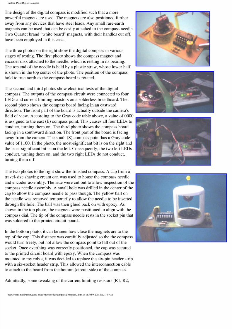
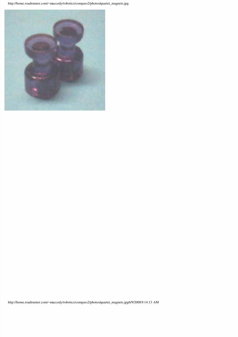
e design of the digital compass is modified such that a more
werful magnets are used. The magnets are also positioned further
way from any devices that have steel leads. Any small rare-earth
agnets can be used that can be easily attached to the compass needle.
wo Quartet brand "white board" magnets, with their handles cut off,
ve been employed in this case.
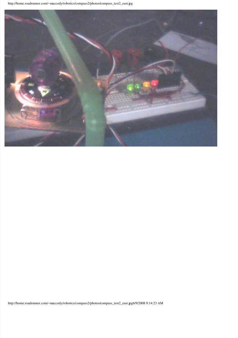
e three photos on the right show the digital compass in various
ges of testing. The first photo shows the compass magnet andcoder disk attached to the needle, which is resting in its bearing.
e top end of the needle is held by a plastic straw, whose lower half
shown in the top center of the photo. The position of the compass
ld to true north as the compass board is rotated.
e second and third photos show electrical tests of the digital
mpass. The outputs of the compass circuit were connected to four
EDs and current limiting resistors on a solderless breadboard. The
cond photo shows the compass board facing in an eastward
ection. The front part of the board is actually outside the camera's
ld of view. According to the Gray code table above, a value of 0000assigned to the east (E) compass point. This causes all four LEDs to
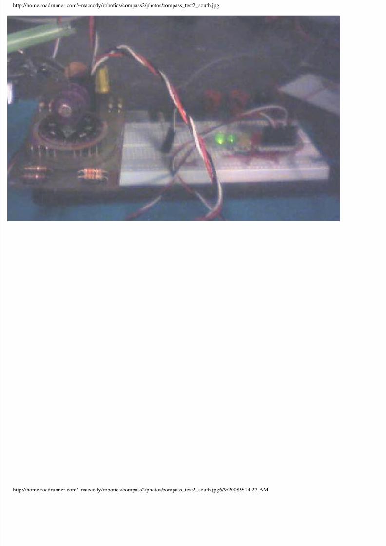
nduct, turning them on. The third photo shows the compass board
cing in a southward direction. The front part of the board is facing
way from the camera. The south (S) compass point has a Gray code
lue of 1100. In the photo, the most-significant bit is on the right and
e least-significant bit is on the left. Consequently, the two left LEDs
nduct, turning them on, and the two right LEDs do not conduct,
ning them off.
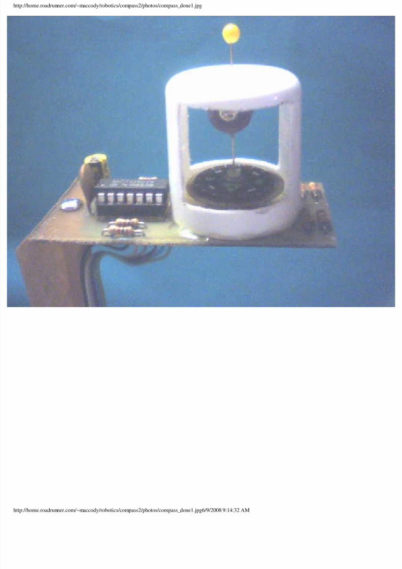
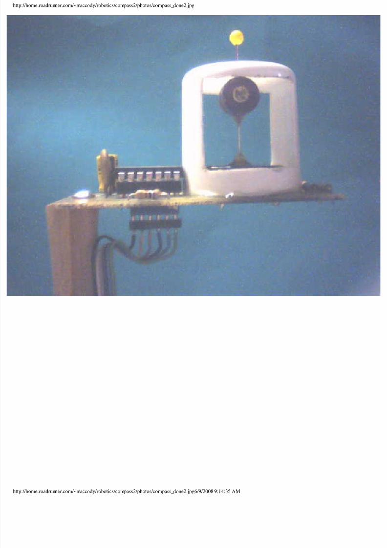
e two photos to the right show the finished compass. A cap from avel-size shaving cream can was used to house the compass needle
d encoder assembly. The side were cut out to allow inspection of the
mpass needle assembly. A small hole was drilled in the center of the
p to allow the compass needle to pass though. The yellow ball on
e needle was removed temporarily to allow the needle to be inserted
ough the hole. The ball was then glued back on with epoxy. As
own in the top photo, the magnets were positioned to align with the
mpass dial. The tip of the compass needle rests in the socket pin that
as soldered to the printed circuit board.
the bottom photo, it can be seen how close the magnets are to thep of the cap. This distance was carefully adjusted so the the compass
ould turn freely, but not allow the compass point to fall out of the
cket. Once everthing was correctly positioned, the cap was secured
the printed circuit board with epoxy. When the compass was
ounted to my robot, it was decided to replace the six-pin header strip
th a six-socket header strip. This allowed the interconnection cable
attach to the board from the bottom (circuit side) of the compass.
dmittedly, some tweaking of the current limiting resistors (R1, R2,
tp://home.roadrunner.com/~maccody/robotics/compass2/compass2.html (4 of 5)6/9/2008 9:13:14 AM

8/13/2019 Sixteen-Point Digital Compass
http://slidepdf.com/reader/full/sixteen-point-digital-compass 5/16
ixteen-Point Digital Compass
, and R4) must be performed to obtain the desired switching
rformance. I used resistors with 20% tolerance, so I ended up
cking and choosing resistors until the transistors switched properly
the encoder disk rotated. A more repeatable circuit design would
obably require resistors with better tolerance ratings (10% or 5%).
any rate, the compass sensor does work once the resistances are
operly selected.
006, 2007 Mac A. Cody
t updated Friday, March 9, 2007
tp://home.roadrunner.com/~maccody/robotics/compass2/compass2.html (5 of 5)6/9/2008 9:13:14 AM
8/13/2019 Sixteen-Point Digital Compass
http://slidepdf.com/reader/full/sixteen-point-digital-compass 6/16
ttp://home.roadrunner.com/~maccody/robotics/compass2/photos/board_bottom.jpg
ttp://home.roadrunner.com/~maccody/robotics/compass2/photos/board_bottom.jpg6/9/2008 9:13:47 AM
8/13/2019 Sixteen-Point Digital Compass
http://slidepdf.com/reader/full/sixteen-point-digital-compass 7/16
ttp://home.roadrunner.com/~maccody/robotics/compass2/photos/board_top.jpg
ttp://home.roadrunner.com/~maccody/robotics/compass2/photos/board_top.jpg6/9/2008 9:14:00 AM

8/13/2019 Sixteen-Point Digital Compass
http://slidepdf.com/reader/full/sixteen-point-digital-compass 8/16
ttp://home.roadrunner.com/~maccody/robotics/compass2/photos/board_side.jpg
ttp://home.roadrunner.com/~maccody/robotics/compass2/photos/board_side.jpg6/9/2008 9:14:04 AM
8/13/2019 Sixteen-Point Digital Compass
http://slidepdf.com/reader/full/sixteen-point-digital-compass 9/16
ttp://home.roadrunner.com/~maccody/robotics/compass2/photos/weak_compass.jpg
ttp://home.roadrunner.com/~maccody/robotics/compass2/photos/weak_compass.jpg6/9/2008 9:14:07 AM
8/13/2019 Sixteen-Point Digital Compass
http://slidepdf.com/reader/full/sixteen-point-digital-compass 10/16
ttp://home.roadrunner.com/~maccody/robotics/compass2/photos/quartet_magnets.jpg
ttp://home.roadrunner.com/~maccody/robotics/compass2/photos/quartet_magnets.jpg6/9/2008 9:14:13 AM
8/13/2019 Sixteen-Point Digital Compass
http://slidepdf.com/reader/full/sixteen-point-digital-compass 11/16
ttp://home.roadrunner.com/~maccody/robotics/compass2/photos/compass_test1.jpg
ttp://home.roadrunner.com/~maccody/robotics/compass2/photos/compass_test1.jpg6/9/2008 9:14:18 AM
8/13/2019 Sixteen-Point Digital Compass
http://slidepdf.com/reader/full/sixteen-point-digital-compass 12/16
ttp://home.roadrunner.com/~maccody/robotics/compass2/photos/compass_test2_east.jpg
ttp://home.roadrunner.com/~maccody/robotics/compass2/photos/compass_test2_east.jpg6/9/2008 9:14:23 AM
8/13/2019 Sixteen-Point Digital Compass
http://slidepdf.com/reader/full/sixteen-point-digital-compass 13/16
ttp://home.roadrunner.com/~maccody/robotics/compass2/photos/compass_test2_south.jpg
ttp://home.roadrunner.com/~maccody/robotics/compass2/photos/compass_test2_south.jpg6/9/2008 9:14:27 AM
8/13/2019 Sixteen-Point Digital Compass
http://slidepdf.com/reader/full/sixteen-point-digital-compass 14/16
8/13/2019 Sixteen-Point Digital Compass
http://slidepdf.com/reader/full/sixteen-point-digital-compass 15/16
ttp://home.roadrunner.com/~maccody/robotics/compass2/photos/compass_done2.jpg
ttp://home.roadrunner.com/~maccody/robotics/compass2/photos/compass_done2.jpg6/9/2008 9:14:35 AM

8/13/2019 Sixteen-Point Digital Compass
http://slidepdf.com/reader/full/sixteen-point-digital-compass 16/16
![[Compass point] module#1 collegeselection](https://static.fdocuments.us/doc/165x107/54b5f8cc4a7959a3098b4632/compass-point-module1-collegeselection-5584a77d56500.jpg)