Six-servo Robot Arm - RobotShop
18
Six-servo Robot Arm DAGU Hi-Tech Electronic Co., LTD www.arexx.com.cn Six-servo Robot Arm 1
Transcript of Six-servo Robot Arm - RobotShop

Six-servo Robot Arm DAGU Hi-Tech Electronic Co., LTD www.arexx.com.cn
Six-servo Robot Arm
1
Six-servo Robot Arm DAGU Hi-Tech Electronic Co., LTD www.arexx.com.cn
2
1, Introduction 1.1 , Function Briefing
Servo robot, as the name suggests, is the six servo motor-driven
robot arm. Since the arm has a few joints, we can imagine, our human arm,
in addition to shoulder, elbow, and wrist, coupled with the finger joints; there
are a lot of joints. So this robot is the same, with six servo motors to achieve
a simple structure, no one apart from so many joints, but also lack some of
nerve tissue and the nervous system, however, "dexterous hand" (which can
be complexly Assembly, handling or catching eggs), "Humanoid" robot is a
robot on the forefront.
And our six servo arm with wonderful mechanical structure, and its control
system, displayed the 6-DOF robot arm movements control principle. It uses
three pieces of 13 kg torque metal gear, a 3.2 kg, two pieces of 2.3 kg of
servo and some sophisticated combination of aluminum alloy processing
components. At present, our company's robot arm is mainly 390 mm length,
use 32-way controller to control the operation of arm action, the controllers
use atmega168 MCU, and computer RS232 COM communications, and at
the same time it can control 32 servo motors, dual - Power Supply (6 ~ 12 V
SCM power, 4.8 ~ 6 V servo motor power [servo motor power supply Road
Six-servo Robot Arm DAGU Hi-Tech Electronic Co., LTD www.arexx.com.cn
3
1-16 respectively, a 17-32 road supply port]), also a wi-fi Wireless control
module, reserve the ISP downloaded, you can download the MCU controller
program using the STK500 ISP cable.
Six-servo Robot Arm DAGU Hi-Tech Electronic Co., LTD www.arexx.com.cn
1.2, Main Board Power Connector Introduction
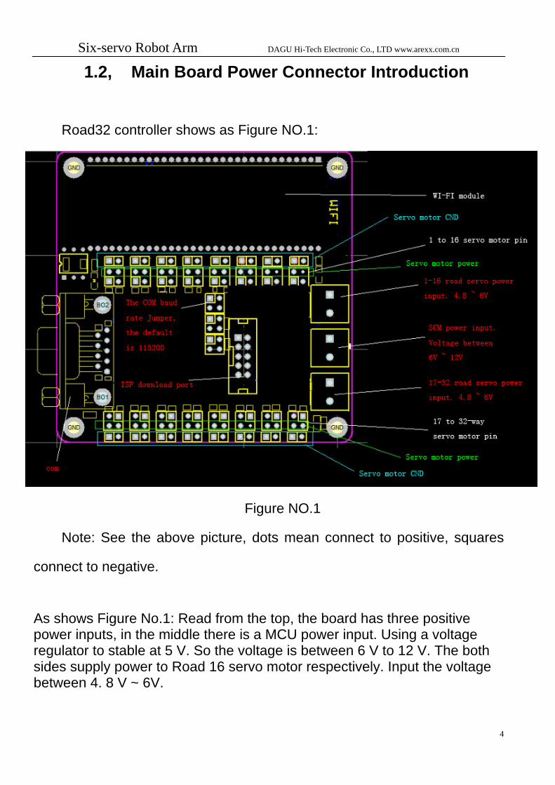
Road32 controller shows as Figure NO.1:
Figure NO.1
Note: See the above picture, dots mean connect to positive, squares
connect to negative.
As shows Figure No.1: Read from the top, the board has three positive power inputs, in the middle there is a MCU power input. Using a voltage regulator to stable at 5 V. So the voltage is between 6 V to 12 V. The both sides supply power to Road 16 servo motor respectively. Input the voltage between 4. 8 V ~ 6V.
4
Six-servo Robot Arm DAGU Hi-Tech Electronic Co., LTD www.arexx.com.cn
5
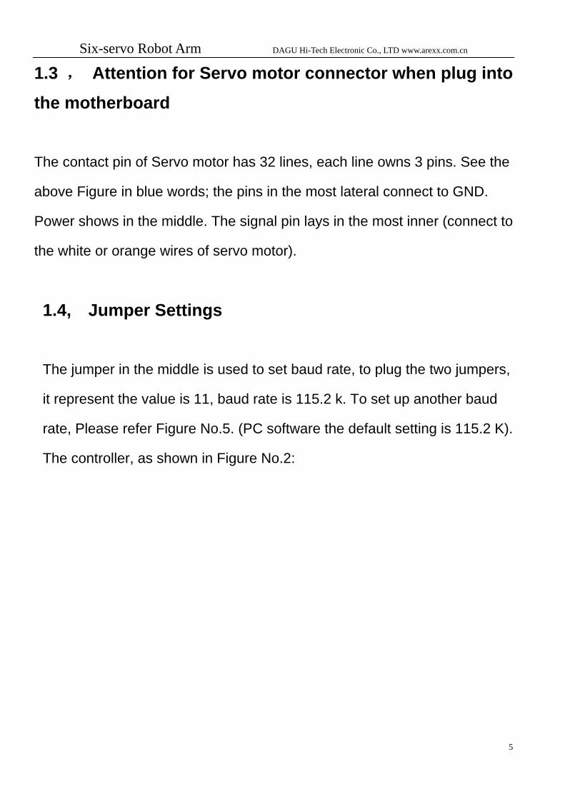
1.3 , Attention for Servo motor connector when plug into
the motherboard
The contact pin of Servo motor has 32 lines, each line owns 3 pins. See the
above Figure in blue words; the pins in the most lateral connect to GND.
Power shows in the middle. The signal pin lays in the most inner (connect to
the white or orange wires of servo motor).
1.4, Jumper Settings
The jumper in the middle is used to set baud rate, to plug the two jumpers,
it represent the value is 11, baud rate is 115.2 k. To set up another baud
rate, Please refer Figure No.5. (PC software the default setting is 115.2 K).
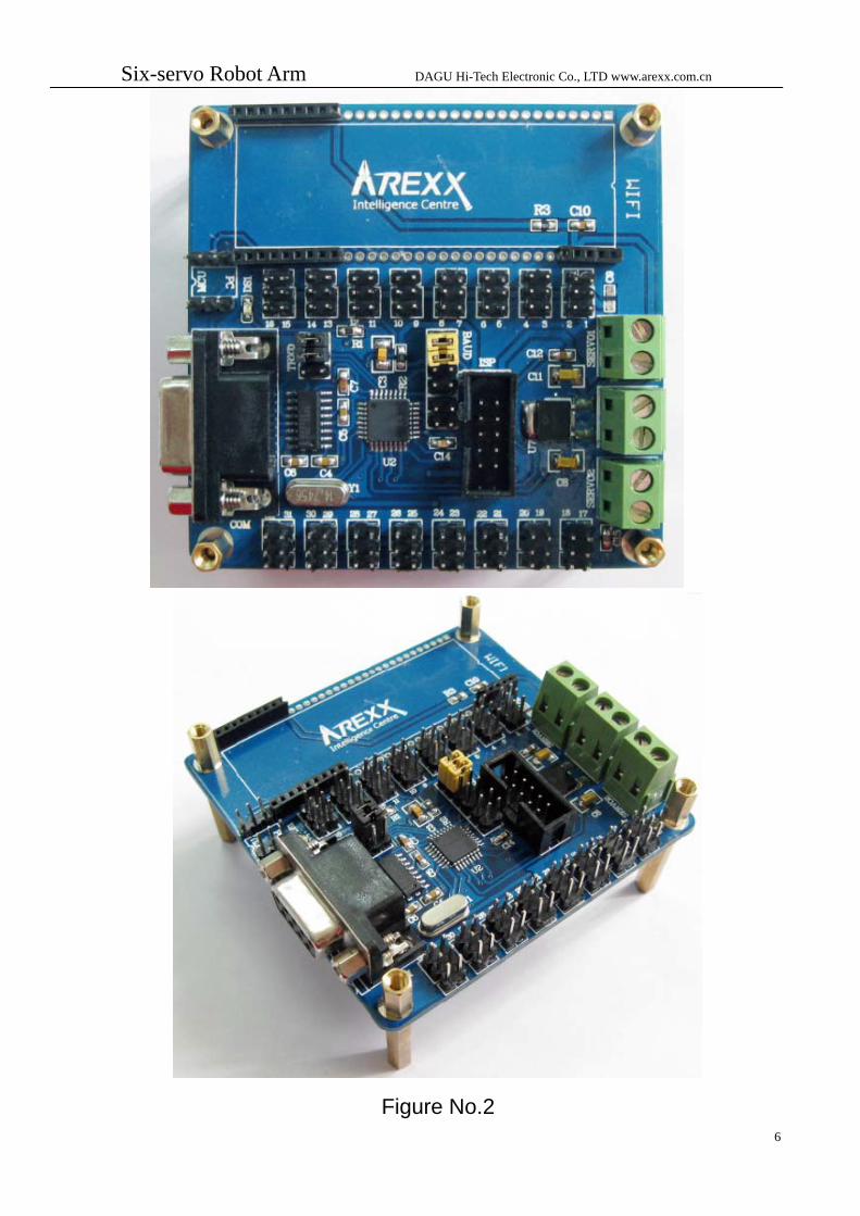
The controller, as shown in Figure No.2:
Six-servo Robot Arm DAGU Hi-Tech Electronic Co., LTD www.arexx.com.cn
Figure No.2
6
Six-servo Robot Arm DAGU Hi-Tech Electronic Co., LTD www.arexx.com.cn
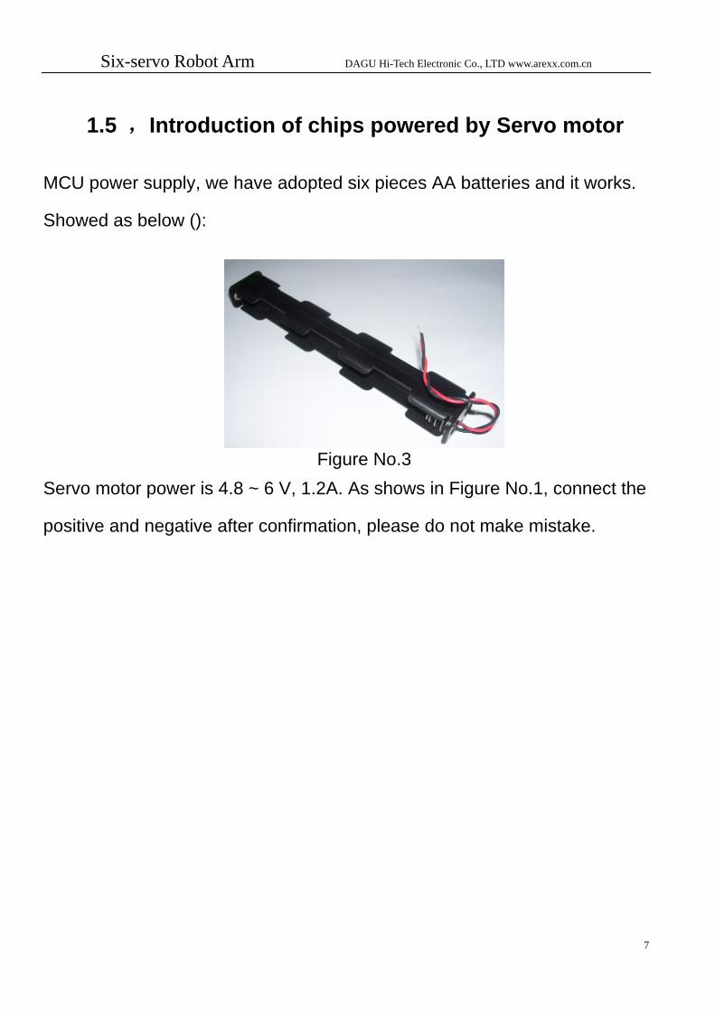
1.5 ,Introduction of chips powered by Servo motor
MCU power supply, we have adopted six pieces AA batteries and it works.
Showed as below ():
Figure No.3
Servo motor power is 4.8 ~ 6 V, 1.2A. As shows in Figure No.1, connect the
positive and negative after confirmation, please do not make mistake.
7

Six-servo Robot Arm DAGU Hi-Tech Electronic Co., LTD www.arexx.com.cn
2 Interfaces
2.1, Interface Briefing
At the same time, PC software, and just a few simple steps can make the
robot move; it is easy and fast for the operator to learn.
Figure No.4
Open the PC operating software, see the interface shown in Figure
No.5, first is to set up the port, see Figure No.5. This interface contains the 8
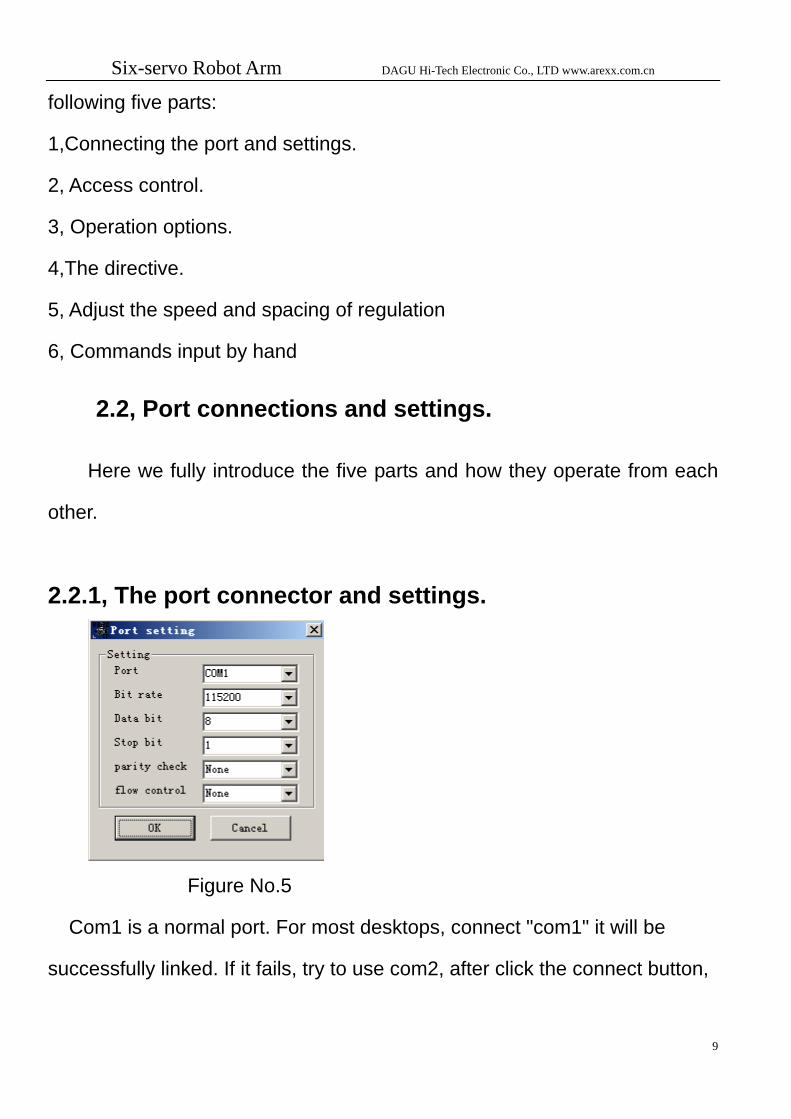
Six-servo Robot Arm DAGU Hi-Tech Electronic Co., LTD www.arexx.com.cn
following five parts:
1,Connecting the port and settings.
2, Access control.
3, Operation options.
4,The directive.
5, Adjust the speed and spacing of regulation
6, Commands input by hand 2.2, Port connections and settings.
Here we fully introduce the five parts and how they operate from each
other.
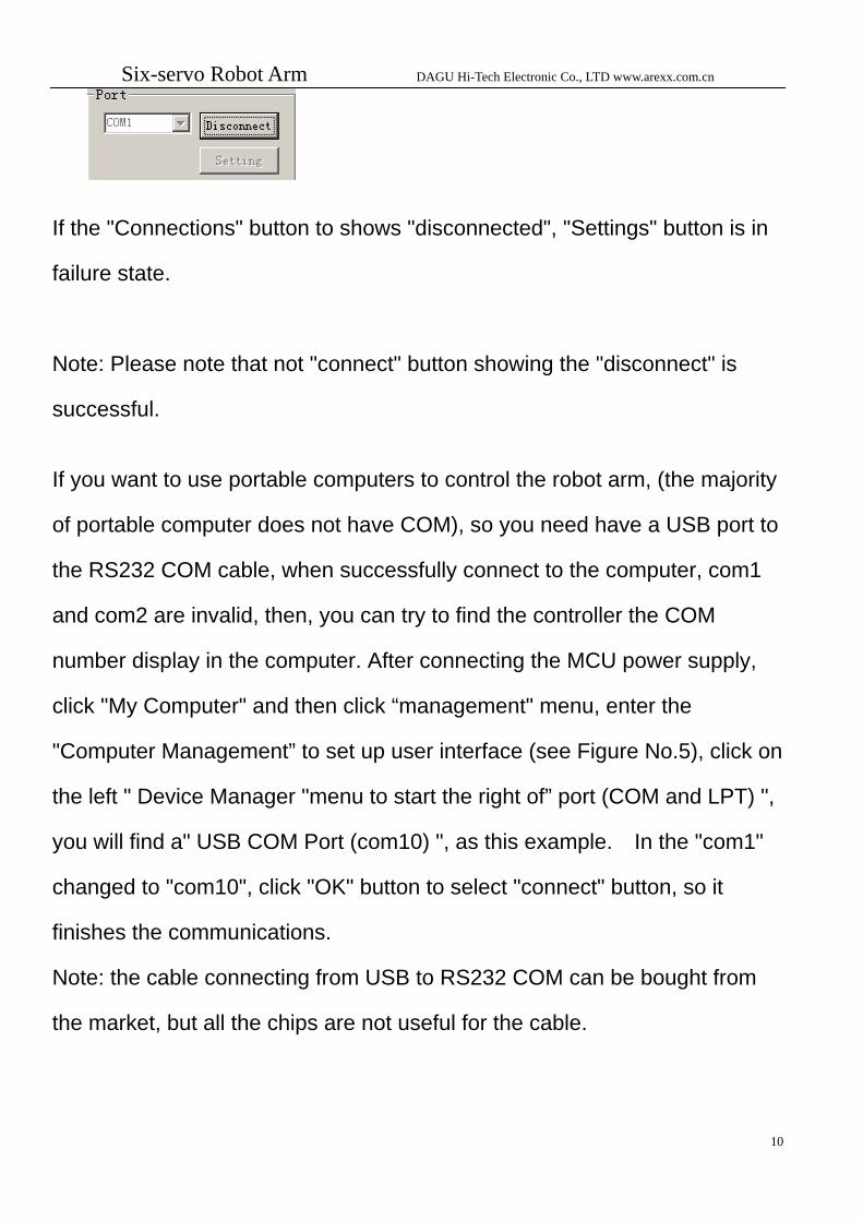
2.2.1, The port connector and settings.
Figure No.5
Com1 is a normal port. For most desktops, connect "com1" it will be
successfully linked. If it fails, try to use com2, after click the connect button,
9
Six-servo Robot Arm DAGU Hi-Tech Electronic Co., LTD www.arexx.com.cn
If the "Connections" button to shows "disconnected", "Settings" button is in
failure state.
Note: Please note that not "connect" button showing the "disconnect" is
successful. If you want to use portable computers to control the robot arm, (the majority
of portable computer does not have COM), so you need have a USB port to
the RS232 COM cable, when successfully connect to the computer, com1
and com2 are invalid, then, you can try to find the controller the COM
number display in the computer. After connecting the MCU power supply,
click "My Computer" and then click “management" menu, enter the
"Computer Management” to set up user interface (see Figure No.5), click on
the left " Device Manager "menu to start the right of” port (COM and LPT) ",
you will find a" USB COM Port (com10) ", as this example. In the "com1"
changed to "com10", click "OK" button to select "connect" button, so it
finishes the communications.
Note: the cable connecting from USB to RS232 COM can be bought from
the market, but all the chips are not useful for the cable.
10
Six-servo Robot Arm DAGU Hi-Tech Electronic Co., LTD www.arexx.com.cn
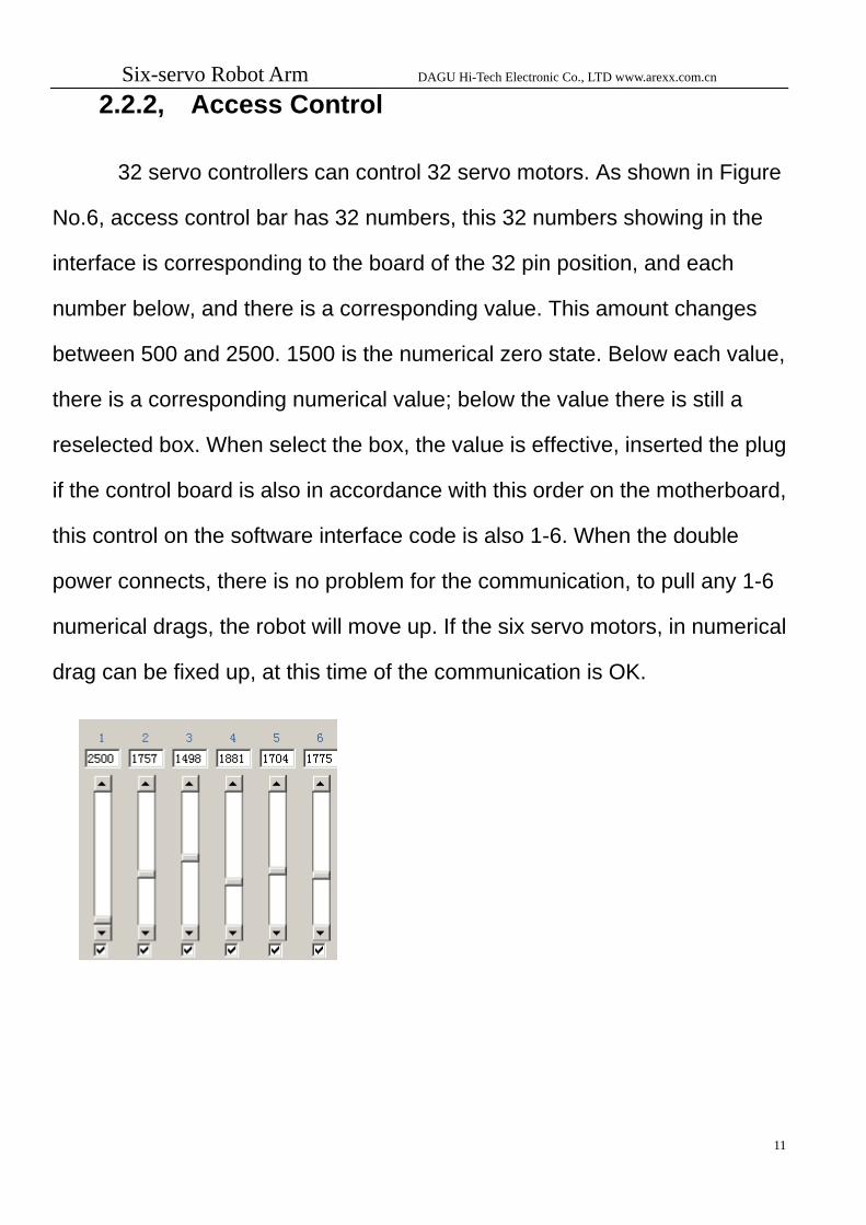
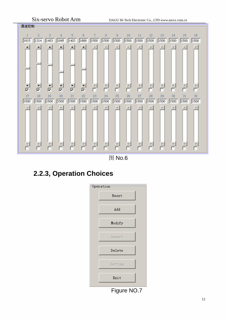
2.2.2, Access Control
32 servo controllers can control 32 servo motors. As shown in Figure
No.6, access control bar has 32 numbers, this 32 numbers showing in the
interface is corresponding to the board of the 32 pin position, and each
number below, and there is a corresponding value. This amount changes
between 500 and 2500. 1500 is the numerical zero state. Below each value,
there is a corresponding numerical value; below the value there is still a
reselected box. When select the box, the value is effective, inserted the plug
if the control board is also in accordance with this order on the motherboard,
this control on the software interface code is also 1-6. When the double
power connects, there is no problem for the communication, to pull any 1-6
numerical drags, the robot will move up. If the six servo motors, in numerical
drag can be fixed up, at this time of the communication is OK.
11
Six-servo Robot Arm DAGU Hi-Tech Electronic Co., LTD www.arexx.com.cn
12
图 No.6
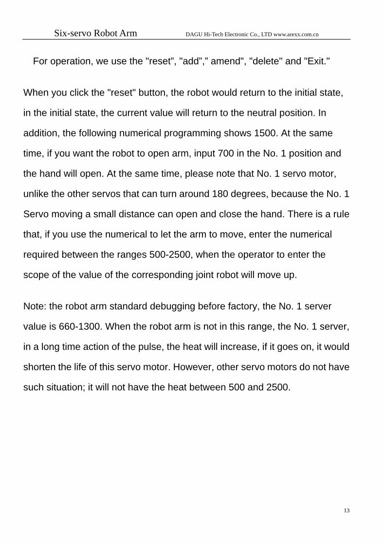
2.2.3, Operation Choices
Figure NO.7
Six-servo Robot Arm DAGU Hi-Tech Electronic Co., LTD www.arexx.com.cn
13
For operation, we use the "reset”, "add”,” amend", "delete" and "Exit."
When you click the "reset" button, the robot would return to the initial state,
in the initial state, the current value will return to the neutral position. In
addition, the following numerical programming shows 1500. At the same
time, if you want the robot to open arm, input 700 in the No. 1 position and
the hand will open. At the same time, please note that No. 1 servo motor,
unlike the other servos that can turn around 180 degrees, because the No. 1
Servo moving a small distance can open and close the hand. There is a rule
that, if you use the numerical to let the arm to move, enter the numerical
required between the ranges 500-2500, when the operator to enter the
scope of the value of the corresponding joint robot will move up.
Note: the robot arm standard debugging before factory, the No. 1 server
value is 660-1300. When the robot arm is not in this range, the No. 1 server,
in a long time action of the pulse, the heat will increase, if it goes on, it would
shorten the life of this servo motor. However, other servo motors do not have
such situation; it will not have the heat between 500 and 2500.
Six-servo Robot Arm DAGU Hi-Tech Electronic Co., LTD www.arexx.com.cn
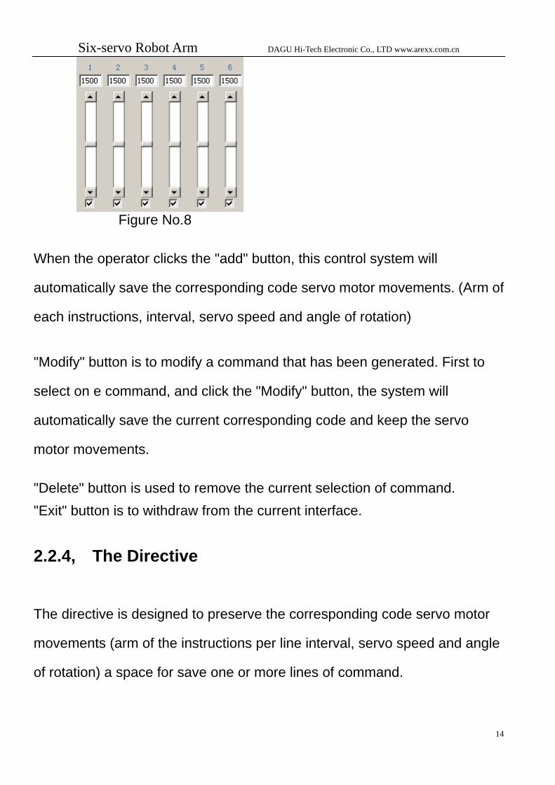
Figure No.8
When the operator clicks the "add" button, this control system will
automatically save the corresponding code servo motor movements. (Arm of
each instructions, interval, servo speed and angle of rotation)
"Modify" button is to modify a command that has been generated. First to
select on e command, and click the "Modify" button, the system will
automatically save the current corresponding code and keep the servo
motor movements. "Delete" button is used to remove the current selection of command. "Exit" button is to withdraw from the current interface.
2.2.4, The Directive
The directive is designed to preserve the corresponding code servo motor
movements (arm of the instructions per line interval, servo speed and angle
of rotation) a space for save one or more lines of command.
14
Six-servo Robot Arm DAGU Hi-Tech Electronic Co., LTD www.arexx.com.cn
2.2.5, Adjust the Speed and Spacing of Regulation Adjust the speed of each servo motor to control the rotational speed. The default system for 300 is better; making the numerical too big is bad for robot usage. Regulation time adjustment is to adjust the interval of movements.
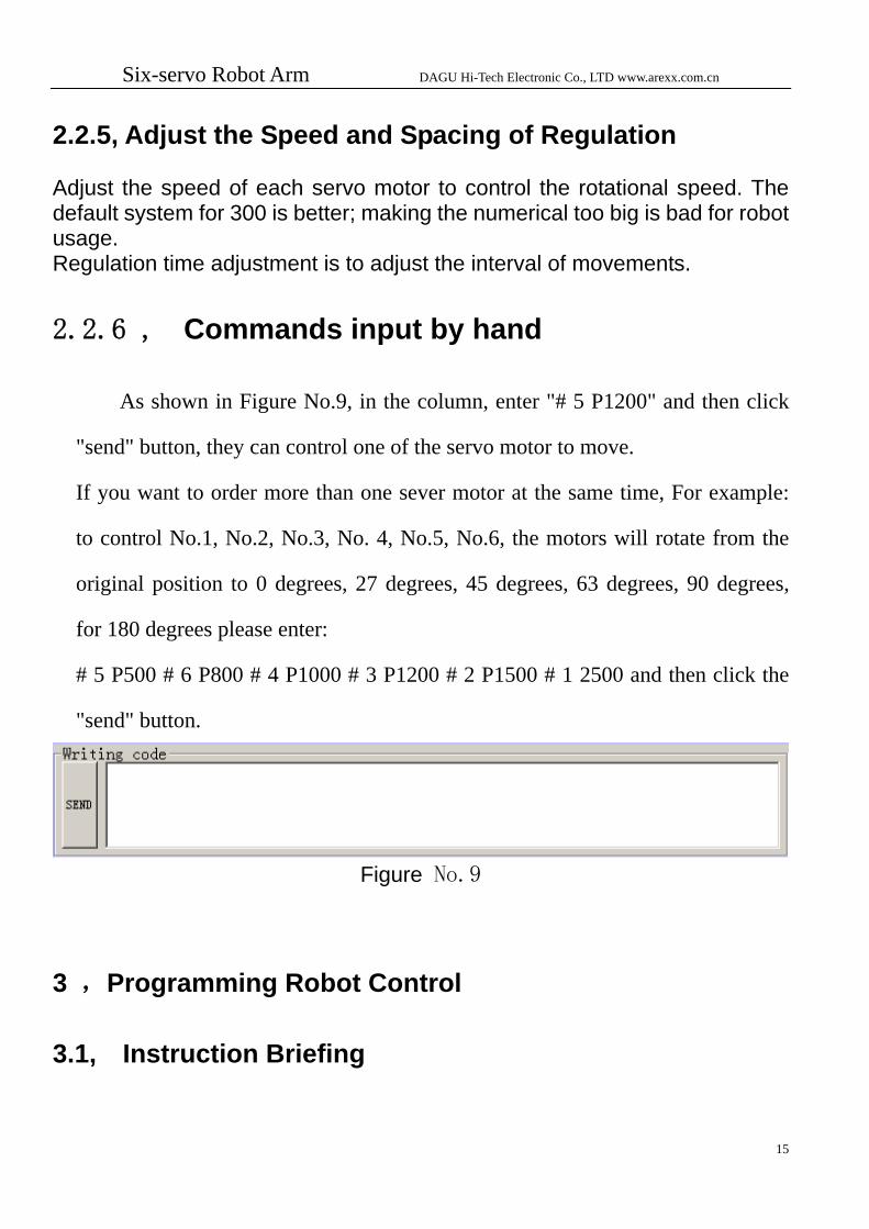
2.2.6 , Commands input by hand
As shown in Figure No.9, in the column, enter "# 5 P1200" and then click
"send" button, they can control one of the servo motor to move.
If you want to order more than one sever motor at the same time, For example:
to control No.1, No.2, No.3, No. 4, No.5, No.6, the motors will rotate from the
original position to 0 degrees, 27 degrees, 45 degrees, 63 degrees, 90 degrees,
for 180 degrees please enter:
# 5 P500 # 6 P800 # 4 P1000 # 3 P1200 # 2 P1500 # 1 2500 and then click the
"send" button.
Figure No.9
3 ,Programming Robot Control
3.1, Instruction Briefing
15
Six-servo Robot Arm DAGU Hi-Tech Electronic Co., LTD www.arexx.com.cn
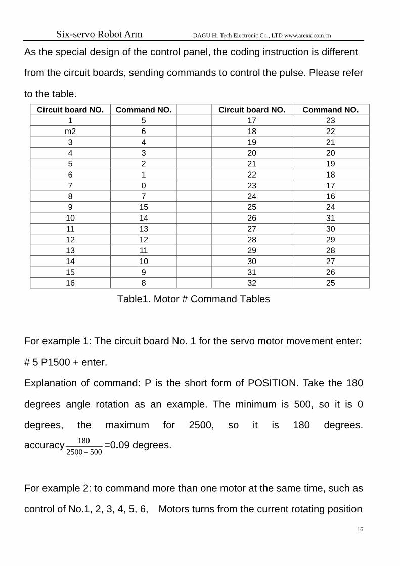
As the special design of the control panel, the coding instruction is different
from the circuit boards, sending commands to control the pulse. Please refer
to the table. Circuit board NO. Command NO. Circuit board NO. Command NO.
1 5 17 23 m2 6 18 22 3 4 19 21 4 3 20 20 5 2 21 19 6 1 22 18 7 0 23 17 8 7 24 16 9 15 25 24 10 14 26 31 11 13 27 30 12 12 28 29 13 11 29 28 14 10 30 27 15 9 31 26 16 8 32 25
Table1. Motor # Command Tables
For example 1: The circuit board No. 1 for the servo motor movement enter:
# 5 P1500 + enter.
Explanation of command: P is the short form of POSITION. Take the 180
degrees angle rotation as an example. The minimum is 500, so it is 0
degrees, the maximum for 2500, so it is 180 degrees.
accuracy5002500
180−
=0.09 degrees.
For example 2: to command more than one motor at the same time, such as
control of No.1, 2, 3, 4, 5, 6, Motors turns from the current rotating position
16

Six-servo Robot Arm DAGU Hi-Tech Electronic Co., LTD www.arexx.com.cn
17
to 0 degrees, 27 degrees, 45 degrees, 63 degrees, 90 degrees , 180
degrees, enter:
# 5 P500 # 6 P800 # 4 P1000 # 3 P1200 # 2 P1500 # 1 2500 enter
For example 3: time controlling, When controlling the NO.1 servo motor
from its current location, move 180 degrees, the total time is one second,
# 5 P2500 T1000 Enter
Explanation of command:T means time, and 1000 is 1000 ms = 1 second. If
0.5 seconds, then change to 500.
3.2, add actions, the system automatically generate coherent actions 3.2.1, through the operation column click the "Add" button to
generate coherent actions
when the arm moves to a position that is what you need, click "Add" button, it will
save the rotating angle of each servo motor(that is the robot movement situation),
the current movement speed are kept. When you save more commands, click "run"
button, can produce coherent actions.
3.2.2 To generate coherent actions by input the codes with hands
in column.
Six-servo Robot Arm DAGU Hi-Tech Electronic Co., LTD www.arexx.com.cn
18
Like the 2.2.6 operation, input the codes by hands, also allows a number of joints
work continuously.
Servo motor specifications and parameters as follows: 12KG metal gear of the servo motor: Size: 40.4 * 19.8 * 36 mm Weight: 48 g Speed: 0.22 sec/60 ° Output Torque: 13 kg • cm 3.2kg servo motor: Size: 39.5 x20.0x35.5mm Weight: 41 g Speed: 0.27 sec/60 ° Torque output: 3.2 kg • cm 3.2kg servo motor: Size: 28 x14x29.8mm Weight: 18 g Speed: 0.13 sec/60 ° Torque output: 2.3 kg • cm


![Six-servo Robot Arm - Génération Robots · Six-servo Robot Arm DAGU Hi-Tech Electronic Co., LTD 3 1-16 respectively, a 17-32 road supply port]), also a wi-fi Wireless control module,](https://static.fdocuments.us/doc/165x107/5e80785bb6264e08cd270c3d/six-servo-robot-arm-gnration-six-servo-robot-arm-dagu-hi-tech-electronic-co.jpg)