NASA-CR-166009 · A synopsis of the major activites accomplished ... Hydraulic/ Control Series...
24
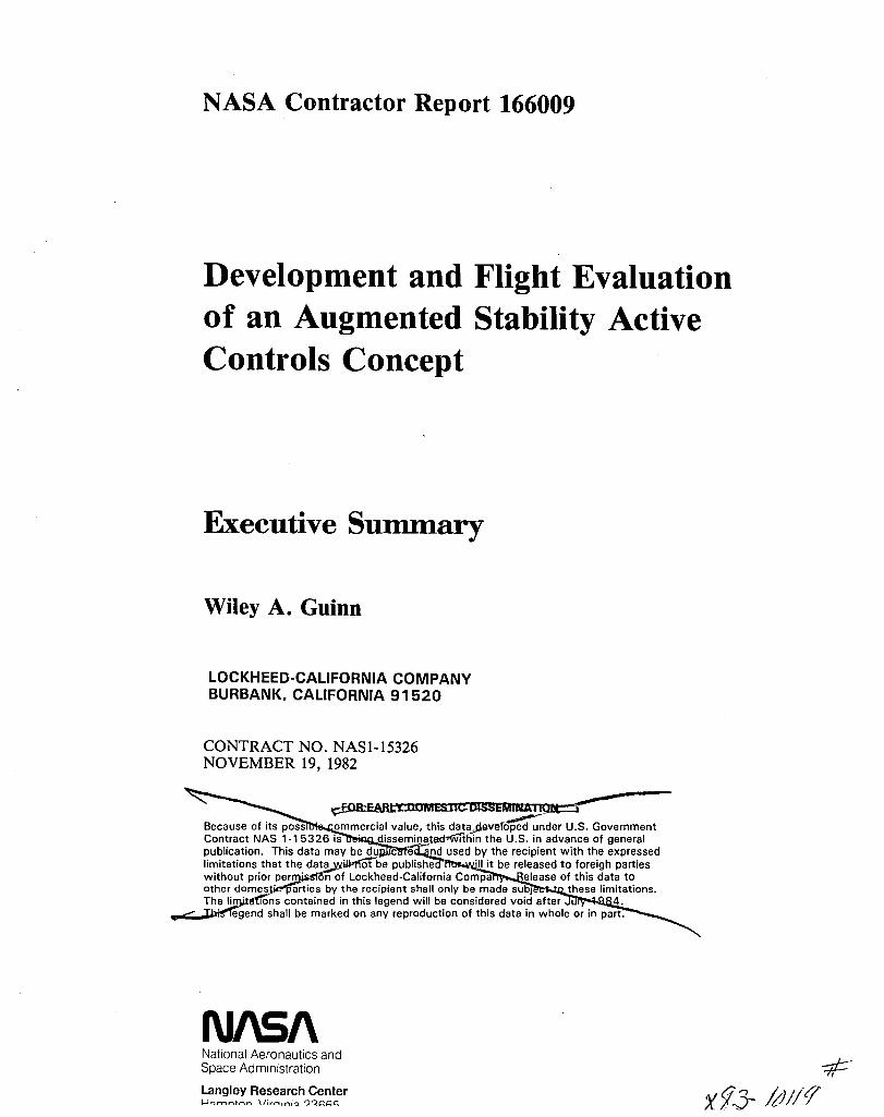
Development and Flight Evaluation of an Augmented Stability Active Controls Concept Executive Summary Wiley A. Guinn LOCKHEED-CALIFORNIA COMPANY BURBANK, CALIFORNIA 91520 CONTRACT NO. NASI-15326 NOVEMBER 19, 1982 NASA-CR-166009 19850002698 1111111111111 IIII 11111 II1I1 I1III 111111111 1111 NF01906 , DOMESTIC DISSEMlNATiolii) 'Because of its possible under U.S. Gover!1me.nt=--- Contract-NAS 1-15326 is being disseminated within the publication. Thls'-data_may be duplicated and LJsed by-tne-r'ecipient with the expressed limitations that the data-iNill=nocoe=pL.blished nor will it be released to foreigh parties without prior permission of Lockheed-California Company. Release of this data to other domestic-parties by the recipient shillionlYcbe made subject to these limitations. The limifatlons contained in this legend will be consiCl"eted_void after July 1984. -Jhislegend shall be marked on any reproduction of this datain-·whale.or in part. f: D '.1 L U..'i hhb. Ii \i,H) NI\S/\ National Aeronautics and Space Administration Langley Research Center Hampton, Virginia 23665 U,NGLEY RESEARCH CENTER liBRARY, Nl,SA Hl\i:.P.TOi:l, VIRGINIA, https://ntrs.nasa.gov/search.jsp?R=19850002698 2018-06-09T01:45:29+00:00Z
Transcript of NASA-CR-166009 · A synopsis of the major activites accomplished ... Hydraulic/ Control Series...

Development and Flight Evaluation of an Augmented Stability Active Controls Concept
Executive Summary
Wiley A. Guinn
LOCKHEED-CALIFORNIA COMPANY BURBANK, CALIFORNIA 91520
CONTRACT NO. NASI-15326 NOVEMBER 19, 1982
NASA-CR-166009 19850002698
1111111111111 IIII 11111 II1I1 I1III 111111111 1111 NF01906
, ~F.OR·EAR-lY DOMESTIC DISSEMlNATiolii)
'Because of its possible co~;;;-~~-i-a-I-~~I~.~his datad~~~loped under U.S. Gover!1me.nt=--Contract-NAS 1-15326 is being disseminated within the U.S~il1-advanC6"orgener-al publication. Thls'-data_may be duplicated and LJsed by-tne-r'ecipient with the expressed limitations that the data-iNill=nocoe=pL.blished nor will it be released to foreigh parties without prior permission of Lockheed-California Company. Release of this data to other domestic-parties by the recipient shillionlYcbe made subject to these limitations. The limifatlons contained in this legend will be consiCl"eted_void after July 1984.
-Jhislegend shall be marked on any reproduction of this datain-·whale.or in part. I-"'~
~ H~.~. ~,,'l r,,~-i11 f: ~ D '.1 L U..'i hhb. Ii \i,H) ~ ~
NI\S/\ National Aeronautics and Space Administration
Langley Research Center Hampton, Virginia 23665
U,NGLEY RESEARCH CENTER liBRARY, Nl,SA
Hl\i:.P.TOi:l, VIRGINIA,
https://ntrs.nasa.gov/search.jsp?R=19850002698 2018-06-09T01:45:29+00:00Z
NASA Contractor Report 166009
Development and Flight Evaluation of an Augmented Stability Active Controls Concept
Executive Summary
Wiley A. Guinn
LOCKHEED-CALIFORNIA COMPANY BURBANK, CALIFORNIA 91520
CONTRACT NO. NASI-15326 NOVEMBER 19, 1982
~DOMES:lJebISSEMINAIIQ.tt::l"""'" Because of its POSSI ommercial value, this dataJ1everop~d;;;der U.S. Government Contract NAS 1-15326 is . dissemiQated-wlthin the U.S. in advance of general publication. This data may be du c e nd used by the recipient with the expressed limitations that the data llM'Iotbe publishe ·11 it be released to foreigh parties without prior per· n of Lockheed-California Compa elease of this data to other domes· arties by the recipient shall only be made suo) these limitations. The ~tTOns contained in this legend will be considered void after u~
~egend shall be marked on any reproduction of this data in whole or in part. ~
NI\S/\ National Aeronautics and Space Administration
Langley Research Center '--!":HYH'"'\trH'" \/i ... "ini-:l ')~~&::~
-qp X 1.3- MI/t?
Section
1
1.1
1.2
1.3
1.4
2
2.1
2.2
2.2.1
2.2.2
2.3
2.4
3
4
LIST OF FIGURES
LIST OF TABLES
SUMMARY ...
INTRODUCTION
TABLE OF CONTENTS
Program Objectives
Rationale for Program
Background . . .
OVERVIEW OF PROGRAM
Control Law Development and System Architecture
Component Design, Fabrication, and Test
PACS Evaluation Tests
Aircraft Ground and Flight Tests
AIRCRAFT DESCRIPTION
Flight Test Aircraft Configuration
Pitch Active Control System (PACS)
PACS configuration
PACS architecture .
C.G. Management System
Downrigged Elevator
PACS FLIGHT TEST RESULTS
CONCLUSIONS AND RECOMMENDATIONS
iii
Page
v
v
1
1
1
2
2
2
5
5
6
6
6
6
6
9
9
9
16
17
Figure
1
2
3
4
5
6
7
8
9
10
11
Table
1
LIST OF FIGURES
Near-term PACS program development activities.
Flight test airplane (L-1011 SIN 1001)
Longitudinal control system with PACS.
PACS avionics system architecture ..
PACS pallet installation in aircraft sIn 1001.
C.G. management system
C.G. envelope
Elevator control drive system (ELCON 11, left side).
Stabilizer/elevator gearing.
Flight conditions
Average pilot ratings, AACS on
LIST OF TABLES
Flight Conditions
v
Page
3
7
8
10
11
12
13
14 15
17
18
16
DEVELOPHENT AND FLIGHT EVALUATION OF AN AUGHENTED STABILITY ACTIVE
CONTROLS CONCEPT -EXECUTIVE Smn1ARY
w. A. Guinn
Lockheed-California Company Burbank, California
Smft1AP-Y
A pitch active control system (PACS) was developed and flight tested on a wide body jet transport (L-10ll) with a flying-stabilizer/geared-elevator.
Modifications to the baseline aircraft included insiallati9n of the PACS, addition of a transferable water ballast system for center of gravity (c.g.) management, and downrigging the geared elevator 0.09 rad (5 deg) to provide nose down control authority for aft c.g. flight conditions. The PACS consisted of a lagged pitch rate damper to control the short period mode and a compensating feed-forward loop to enhance the control column feel characteristics.
The flight test program was conducted with three different pilots who used Cooper-Harper ratings to quantitatively express their opinion of the aircraft longitudinal handling qualities. The reference flight condition for handling quality evaluation was at 25 perc~nt mac c.g. with PACS off. Tests were performed at high speed flight conditions within the linear stability region at c.g. locations of 25, 35, 37, and 39 percent mac with PACS on and off. The handling qualities with the c.g. at 39 percent mac (+1 perGent static stability margin) and PACS on were judged to be as good as the handling qualities with the c.g. at 25 percent mac and PACS off.
This program has flight demonstrated that a pitch active control system can be designed for a wide-body jet transport which maintains the same handling qualities while the static stability margin is reduced from +15 to +1 percent mac. This technology could now be applied to current aircraft to achieve approximately 2 percent fuel savings for linear stability conditions.
INTRODUCTION
Program Objectives
In the past decade (1972 to 1982) fuel cost has increased from approximately 25 percent to 60 percent of aircraft direct operating cost (DOC). This fuel cost trend was forecast in the early 1970s. Therefore, in 1975 the U.s. Congress requested NASA to set up a program to develop fuel saving technology for commercial transports. Thus, the NASA Aircraft Energy Efficiency (ACEE) program was initiated in 1976.

2
The purpose of the ACEE program is to develop fuel saving technology for commercial transports. The primary goal of the current study was to develop a pitch active control system (PACS) that will maintain good aircraft handling qualities for relaxed static stability (RSS) flight conditons.
Rationale for Prograw
Relative to current subsonic commercial jet transports (e.g. Lockheed L-lOll); reduced area horizontal tail, flight with more aft c.g. locations, and advanced technology wing configurations can result in significant fuel savings. Potential fuel savings are reduced area tail (3 percent), more aft c.g. (2 percent for current wing and 4 percent for advanced wing concepts). The advanced wing configuration, which is not addressed during this study provides a fuel savings that is on the order of 10 percent. Implementation of these concepts to maximize fuel savings reduces the static longitudinal stability and degrades the aircraft handling qualities. Utilization of a PACS is a way to maintain the handling qualities when the fuel saving concepts are implemented.
Background
In 1977 Lockheed received an ACEE program contract for "Accelerated Development and Flight Evaluation of Active Control Concepts for Subsonic Transport Aircraft" (NASl-14690). The contract resulted in development of an aileron active control system (AACS) which was installed on the Lockheed L-lOll-500 in 1980 to allow a 5.8 percent wing span increase and the associated 3 percent fuel savings. Also, studies were conducted to evaluate benefits of a small horizontal tail and a PACS. Piloted flight simulation tests conducted on a moving base simulator showed that a lagged pitched rate damper maintained good flying qualities of the baseline airplane to near neutral static stability in heavy turbulence. This piloted simulation results provided the basis for the current program (NASl-15326) which was initiated in 1978. In May 1980 the program was restructured to test the PACS for RSS by moving the c.g. aft to within +1 percent of the neutral point.
1. OVERVIEW OF PROGRM1
During a previous NASA program (NASA Contract NASl-14690), a PACS preliminary control law was developed and tested on the L-lOll visual flight simulator (VFS) to show handling quality benefits of an active control pitch augmentation system for flight at relaxed static stability conditions. The scope of this program (NASA Contract NASl-15326) was to refine the simulated control laws, develop a PACS system, and demonstrate its capabilities by flight tests.
The activities required for development and test of the PACS are shown by the block diagram in figure 1. A synopsis of the major activites accomplished under each of the major headings shown in the figure are discussed below.

PACS failure analysis
Jl
Handling Control PACS Avionics
Hardware/ Design quality 1-+ surface ~ ~ r+ software ~ ~
architecture - analysis specification criteria requirements requirement
I--
Hydraulic/ Control Series servo ~
Non-linear r-. CSMP f-+ Control law I-- 4 mechanical r+ system ~ f-+ L-l0ll model definition specification verification analysis configuration
Wind tunnel ~
and flight test data ,Ir
Series servo tie-in
~ Linear f-+
Classical control mechanism 1-+ matrices system synthesis -. design
Analysis and test !:'Ievator flight conditions modification defined design
Stress analysis
Weight C.G. management
distrib ution -. system design requirements
PACS VFS test
Avionics Avionics system f-+ compon~nt ~
fabrication test I
I
Series Series PACS servo 1-+ servo r VSS fab ricati on test test
Tie-in I
mechanism fabrication ,
Downrigged . elevator
fabrication
• I Spare elevator
I C_G. management
~ system
1
fabrication
I
I
I Baseline I aircraft ,i
-
t--
~
to-
I--
I""-
Aircraft structure stress analysis
Inertial Loads Operation f-+ f-+ analysis analysis restrictions
~
, Flutter Safety analysis review
, Aircraft
Aircraft 1-+ ground 1-+ Flight tests modifications
tests
Figure 1. - Near-term PACS program development activities.
3

1.1 Control Law Development and System Architecture
Handling qualities criteria and flight conditions for evaluation of the PACS were established. Then, control surface rotational displacements and rates were determined. Wind tunnel tests were performed to verify that a 0.09 rad (5 deg) downrigged elevator provided sufficient nose down control for the aft c.g. flight conditions and to determine aerodynamic loads and hinge moments. Concurrent efforts were directed toward refinement of the PACS con~ trol law and development of the PACS configuration. Existing control system synthesis computer programs were utilized for control law refinement and continuous system modeling programs were used for analytical verification. The PACS configuration was designed to be compatible with the basic L-101l control system and to utilize available PACS components. The architecture was developed by determining the number of redundant components needed to satisfy reliability and safety requirements.
1.2 Component Design, Fabrication, and Test
The components to be developed were divided into four categories: Avionics system, series servo, c.g. management system, and downrigged elevator.
Avionics system mechanization required defining the system architecture. Sensors, digital computers. and associated software, and the test pallet were developed into a unified system that had a compatible interface with the electrohydraulic valves and output arm sensors of the PACS series servo. The sensors (pitch rate gyros, column force, and dynamic pressure) were available at Lockheed as were two Collins ACC-20l computers which were modified according to the refined control laws. The computers were bench tested prior to installation on the vehicle system simulator (VSS).
The series servo (National Water Lift 3010000) and the series servo tie-in mechanism designs existed prior to the start of the program. These components were fabricated during the current program and the series servo was bench tested prior to installation on the VSS.
The c.g. management system was assembled from lead ballast and water tanks that were available from the L-lOll development test program. An electrical system was designed and installed to control the water transfer and dumping.
The downrigged elevator counterbalance arms were modified to prevent interference of the counterbalance weights with the stabilizer upper panels. A spare elevator was reworked for this modification.
During the component design, fabrication,and test activities, support was provided by Loads, Vibration, Flutter, Weight, and Safety Groups as required.
5
6
1.3 PACS Evaluation Tests
Prior to flight testing, the control laws were implemented on the L-1011 moving base visual flight simulator (VFS) and evaluated by the same three pilots. The test time was about 60 hours.
After tests of the individual PACS components were satisfactorily completed, they were installed on the L-1011 vehicle systems simulator (VSS). The VSS is a full size, rigid body simulator of the L-1011. Actual aircraft parts (servos, surfaces, cables, hydraulic systems, etc.) are installed as they would be on the aircraft. Simulated PACS functional tests were conducted which corresponded to the conditions that were to be flight tested.
1.4 Aircraft Ground and Flight Tests
The PACS, c.g. management system, and downrigged elevator were installed on the aircraft and checked out. A ground vibration test was performed to investigate structural modes of the modified aircraft and coupling of the PACS with the structural modes. Flight tests included a flutter clearance test (15 hours) and handling quality evaluation tests (31 hours) with 25, 35, 37, and 39 percent mac c.g. locations. Cooper-Harper ratings were utilized by the pilots to .compare the handling qualities with PACS on and off.
2. AIRCRAFT DESCRIPTION
2.1 Flight Test Aircraft Configuration
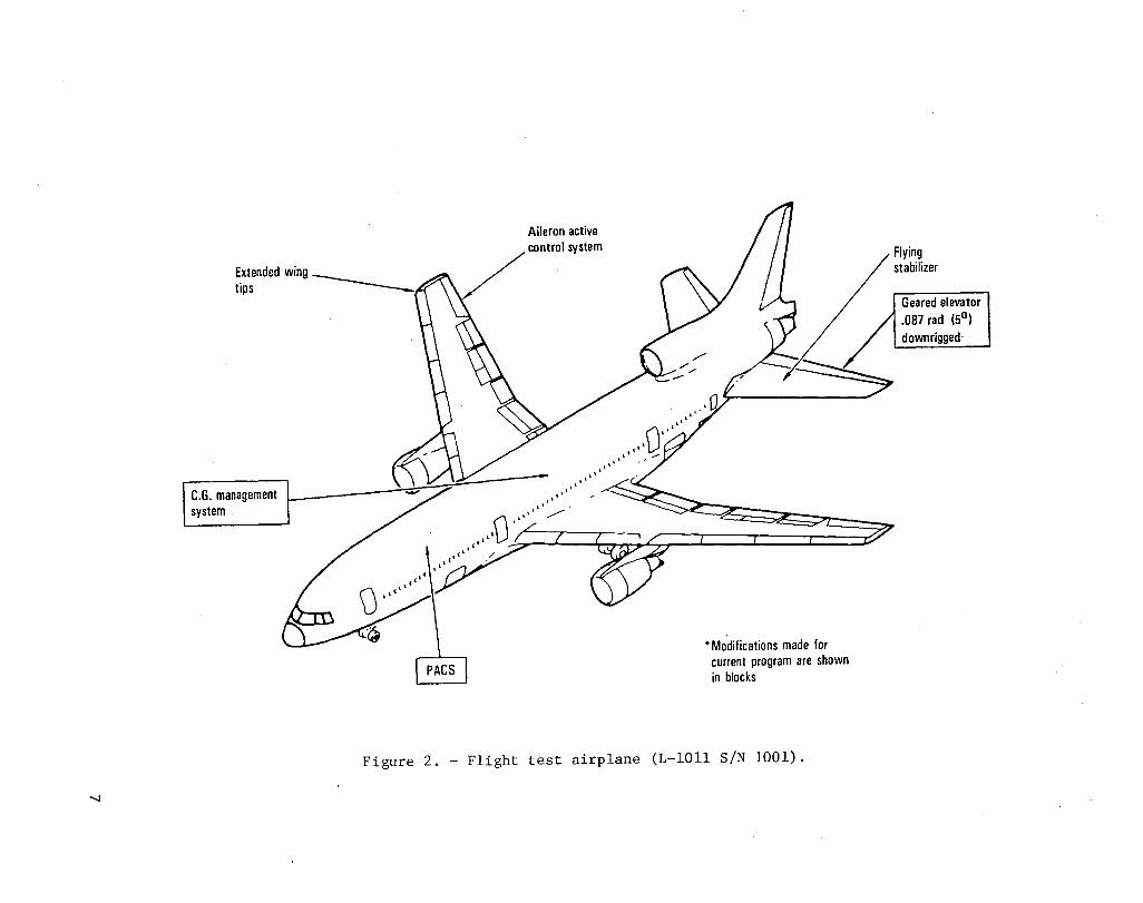
A unique version of the L-10ll aircr~ft was used throughout the PACS program analysis, design, and flight test. Features of the aircraft are shown in figure 2. The test aircraft (SiN 1001) is a basic L-10ll-l with extendedspan wing and aileron active control system (AACS) which were installed during a previous contract (NASl-14690). Modifications during this program include the items shown in the blocks: PACS, c.g. management system, and downrigged elevator.
2.2 Pitch Active Control System (PACS)
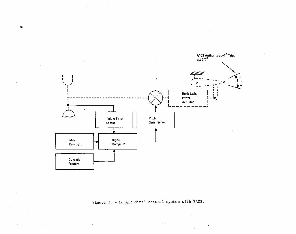
2.2.1 PACS configuration.- A simple block diagram of the longitudinal control system of the Lockheed L-1011 aircraft equipped with PACS is depicted in figure 3. The existing control system prior to installation of the PACS is represented by the dashed lines. PACS components and associated signal flow paths are represented by the solid lines. Three types of sensors provide analog signals to the digital computer. These sensors are pitch rate, column force, and dynamic pressure. The computer provides control signals to a limited authority pitch series servo. The series servo output is summed with the pilot input to drive the horizontal power actuator which rotates the stabilizer.
.....,
Aileron active
/ ""Iml ",.tom
", O ",
IlLL'" .....-
I,ll .'
" " " "
• Modifications made for current program are shown in blocks
Figure 2. - Flight test airplane (L-1011 SiN 1001) .
Flying stabilizer
Geared elevator .087 rad (5°) downrigged-
():)
I I ) \ /
'r I I . ~-----------------------------
J ... / ,
Jmmn)
Pitch Rate Gyro
Dynamic Pressure
Colum Force Sensor
Digital Computer
Pitch Series Servo
PACS Authority at _1 0 Trim is:!: 3/40
~ I • ".L_L.. _______ _ o _~ \ __ .,.-r
----- I I
r - - -~r;; S~b-:- - -1 1 f -~ Power L_ ~Ol
I Actu ator I"
~ L _________ J
Figure 3. - Longitudinal control system with PACS.

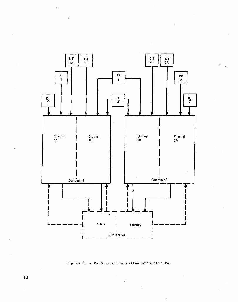
2.2.2 PACS architecture. - The architecture of the PACS is shown in figure 4. The two dual-channel computers are modified Collins ACC-20l digital computers. The column-minus-trim (C-T) signals from the force sensors have a quadruplex arrangement so that a separate signal is sent to each computer channel. The pitch rate (PR) and dynamic pressure (Q ) sensors have a triplex arrangement that provides separate signals to theCA channels and a shared signal to the B channels.
The series servo is a National Water Lift 3010000 servomechanism which has an active/standby channel arrangement. Computer 1 provides control signals to the active channel and Computer 2 provides control signals to the standby channel. The dashed lines between the series servo and the computer in figure 4 represent servo output position feedback signals.
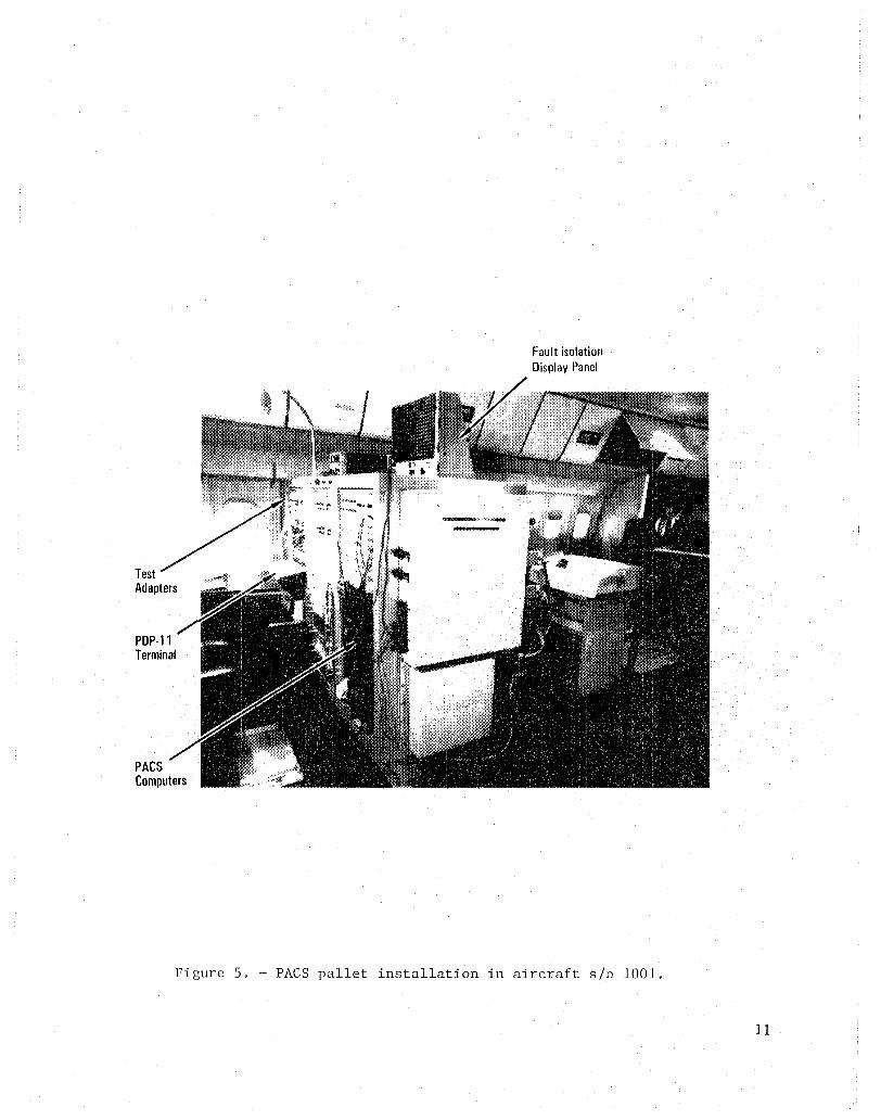
Figure 5 shows the avionics test pallet with PACS computers and associated equipment installed in the flight test aircraft. PACS computers are the block boxes installed in the near lower part of the pallet. The pallet also contains computer wiring intercept capability, magnetic core memories for PACS program storage, and a Digital Equipment Corporation PDP-II terminal for interfacing with the transfer busses of each PACS computer.
2.3 C.G. Management System
The c.g. management system consisted of fixed ballast (lead and water) and a transferable water ballast system as shown in figure 6. The transferable water ballast system was installed in the forward and center cargo compartments of the aircraft as shown in the figure.
Figure 7 shows the c.g. envelope of the aircraft. A typical example of c.g. management is shown in the figure. Starting with the operation empty weight (OEW) , the fixed lead ballast is added. Then, the fixed water ballast and transferable water are added to provide the zero fuel weight (ZFW). The remainder of the cycle shows addition of fuel, transfer of water to the aft tanks, fuel burned, and transfer of water to the forward tanks. For handling quality tests the c.g. limits were maintained between 25 and 39 percent mac.
2.4 Downrigged Elevator
The elevator was downrigged 0.087 rad (5 deg) to provide the required nose down control authority for aft c.g. flight conditions.
Each elevator on the L-I011 is independently connected by a mechanical system to the horizontal stabilizer as shown in figure 8. This system consists of a drive cable, return cable, quadrant (unsymmetrical cam), and an elevator push rod. The drive and return cables are attached to the fuselage structure at one end and the quadrant at the other end. Consequently, as the flying stabilizer is rotated over the range of +0.017 rad (+1 deg) (trailing edge down) to 0.244 rad (-14 deg), the unsymmetrical cam action of the quadrant moves the elevator push rod to rotate the elevator as shown in figure 9 for the standard and downrigged elevator configurations.
9
10
Qc 1
~
• 1 1 1 1 1 1
PR 1
Ir
Channel 1A
CoT 1A
I I I I I I I
CoT 18
Channel 18
Computer 1
I--
I
PR 3
r- Qc
3
t 1 I 1 _I _
~
,
Channel 28
CoT 28
,
I I I I I I •
CoT 2A
Ir
Com~uter 2
PR 2
Channel 2A
• I 1 1 1 I I
L------I Active Standby l _____ ..J
I L ___ ~i~e~ ___ .J
Figure 4. - PACS avionics system architecture.
Qc 2
!
PDP·ll Terminal
PACS Computers
Fault isolation Display Panel
Figure 5. - PACS pallet installation in aircraft sin 1001.
11

...... N
Lead ballast 680 kg (1500 Ibs) lead
Fixed water ballast 7 w2ter tanks 5897 kg (1300 Ibs)
Lead ballast 3629 kg (8000<lbs)
Transfer rate 453 ~ ~ l (1000 Ib/m'.) .. 6 kg/min . m time 16 . -
-----:::::--_< ___ mm ~
~... '"'y-v'"n\
water ballast 8 empty water tanks Dump rate
7257 kg (16000 Ibs) 907.2 kg/min (2000Ibs/min) time 16 min
Figure 6. C.G. Management System
Figure 6. - C.G. management system.
Lead ballast 4423 kg (9750 Ibs)

..... w
Percent mac
103
kg 103
1b 15 17 19 21 23 25 27 ~u " Y Y j' 204 (450) j i ( i
181 (400)
... ..c: ~ 159 (350)
:s:
136 (300)
113 (250)
-17 3 (-15)
-11 5 (-10)
-58 H)
Maximum TOGW
o
Moment About 0 25 mac -
Flgure 7. - C.G. envelope .
58 (5)
11 5 (10)
17 3 106 em-kg (15) 106m-lb

14
I
/
HOrizontal Stabilizer
i-~-~ //--~_= . ;/~l~'''''''''''''''''''''''~
/
_v Quadrant ~,./
~ /'./ /' / E,,,,,,,,·",,,·od ,,~ ~ ,... ~ S".,'"'' .,,0' p"ot
Downngged Elevator
Figure 8. _ Elevator control drive system (ELeON 11, left side).

rad deg
-049 (-28)
-042 (-24) /
/ -035 (-20)
/lW~ /
C / /
'" -028 (-16) / 0 ;:; / '-' ~ / Q)
-021 (-12) Standard L 1011-1 ~/ c ..... E <0 / > Q) -017 (-8) / w
/ /
-007 (-4) ./ ./
" " 0 .". ---(+4) Downng For NASA
ACEE Program
(+8) +004 0 -004 -007 -010 -014 -017 -021 -024 rad (+2) (-2) (-4) (-6) (-8) (-8) (-12) (-14) deg
Stabilizer DeflectIOn
Figure 9. - Stabilizer/elevator gearlng.
15

16
3. PACS FLIGHT TEST RESULTS
E~ght dedicated flying qualities flights were flown by three Lockheed Eng~neering Flight Test pilots to evaluate the PACS. The test aircraft was ballasted to mainta~n 25 percent mac c.g. throughout the first fly~ng qual~t~es fl~ght. During subsequent fl~ghts, the c.g. was moved progress~vely aft to a maximum of 39 percent mac.
The fl~ght condit~ons evaluated are l~sted ~n table 1 and also shown graph~cally in figure 10. The majority of testing was conducted at four representative condit~ons: low alt~tude crUlse (cond~t~on 10), h~gh altitude cruise (condltion 15), max~mum normal operatlng speed (condit~on 16), and landlng approach (condition 18). Spec~f~c tests ~ncluded w~ndup turns to evaluate maneuvering stab~l~ty and control pulses to evaluate dynam~c stabil~ty. PACS effects on trimmab~lity, fl~ght ~n turbulence and the landing approach control task were evaluated qualitatively.
Three d~fferent PACS configurat~ons were ~mplemented ~n the test aircraft and were selected individually in flight for evaluation. The flrst PACS configuration provided only pitch rate damp~ng. The second configurat~on combined pitch rate damp~ng with a feed-forward command to counteract some of the Increased maneuvering force generated by p~tch rate damping. The th~rd conf~guration comb~ned pitch rate damping with a washed-out feed-forward command to reduce the init~al force to maneuver wh~le reta~n~ng h~gher forces dur~ng longterm maneuvers. All three of these configurations were evaluated relative to the basic (PACS off) airplane.
The pilots judged PACS with pitch rate damp~ng and feed-forward washed out to be the best overall conf~guration. Tr~mmab~lity was greatly improved, maneuvering forces were ~ncreased and the maneuvering character~st~cs were substant~ally lmproved ln regions of relaxed stablllty. The feed-forward port~on of the system qu~ckened the response of the basic airplane while the pitch damper prov~ded good stabil~ty in turbulence and at relaxed stat~c stab~lity conditions. Both of these features tended to s~gn~flcantly reduce pilot workload at cruise flight cond~tions. The PACS was also found to reduce pilot workload in the landing approach, although not to the extend found ~n cru~se.
TABLE 1. - FLIGHT CONDITIONS
Flight Condition Speed Altltude/(W/o)
10 Cruise M 83 064 x 106 kg (14 x 106 1b) W/o
15 Cruise M 83 073 x 106 kg (1 6 x 10⁶ 1b) W/o
16 VMO/MMO 370 KCAS 7620 m (25,000 ttl
18 Landing (0 F = 33) 13 Vs Approach
20 Cruise M 83 077 x 106 kg (1 7 x 10⁶ 1b) W/o

103m (103ft) Flight condition 15.2 (50)
20
15
12.2 (40)
9.1 (30)
e.I "CI a ~
< 6.1 (20)
VMO
3.0 (10) Flight condition
a (O)~--~----~----~--~----~----~--~----~-----120 160 200 240 280 320 360 400 440
KEAS Va-KTS
Figure 10. - Flight conditions.
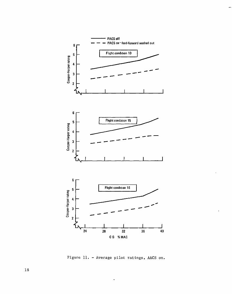
Cooper-Harper pilot ratings for the preferred PACS conf~guration are compared to the basic (PACS-off) airplane for the cruise and high-speed conditions in figure 11. The figure shows that with PACS operating, fly~ng qualit~es at 39 percent mac c.g. were rated as good as the basic airplane at 25 percent c.g.
4. CONCLUSIONS AND RECOMMENDATIONS
Analysis and test performed as part of previous programs indicate that c.g. management can be used to achieve 2 percent fuel savings for aircraft w~th current wing configurations and 4 percent fuel savings for aircraft with advanced technology wings. However, the c.g. must be moved aft which results in relaxed static stability margins and corresponding degradation of handling qualities.
This program has flight demonstrated a pitch active control system for a wide-body jet transport which allows a change in the stat~c stability margin from +15 to +1 percent mac without degradation of the aircraft handling quali~ies within the linear stability region of the flight envelope. The technology can be applied to current-wing configuration aircraft to achieve the 2 percent fuel savings (based on flight test and wind tunnel data) provided that other control systems provide the necessary control for nonlinear stability conditions.
17
18
6
01 5
c: +: f!
4 .... '" e co
~ '"
3 C. Q Q
(..) 2
6
01 5
c: +: f!
4 .... '" e co
:J: .!. 3 '" C. Q Q
(..) 2
6
01 5 c: +: co .... .... 4 '" e co
:J: .!. 3 '" Co Q Q
(..)
24
--- PACSoff PACS on-feed·forward washed out
Flight condition 10
-- --- --- ---
----------- ----
Flight condition 16
-- --- - - -28 32
C G %MAC
36 40
Figure 11. - Average pilot ratings, AACS on.

Subsequent steps to be taken in development of a PACS are to provide control for nonl1near stabil1ty condit10ns, for flight at negat1ve static stab111ty marg1ns (e.g., to -10 percent mac), and for gust load allev1ation. The 10 percent mac negative stab11ity 1S requ1red 1n order to ach1eve the 4 percent fuel sav1ngs for a1rcraft equipped w1th advanced wing configurat1ons. Operat10n at the negat1ve relaxed stat1c stab1l1ty margins require a h1gh reliab1l1ty PAGS. Hardware failures must be extremely 1mprobable for operation in adverse environments (e.g., lightn1ng strikes) and for long per10ds of t1me under commerc1al a1rl1ne operating cond1tions.
The path of technology development for a PAGS that can be 1mplemented on a future generat10n aircraft w1th advanced w1ng technology requ1res cont1nued development and fl1ght test of the advanced PAGS along with a des1gn and analysis study to prov1de the system arch1tecture and component reliab1l1ty necessary to make hazardous fa1lures extremely 1mprobable.
19

1 Report No 2 Government Accession No
NASA CR-166009 4 Title and Subtitle
Development and F11ght Evaluation of an Augmented Stability Active Controls Concept - Executive Summary
7 Author(s)
Wiley A. Guinn
9 Performing Organization Name and Address
Lockheed California Company P.O. Box 551 Burbank, Ca. 91520
12 Sponsoring Agency Name and Address
National Aeronautics and Space Administration Washington, DC 20546
15 Supplementary Notes
F. C. English was the Lockheed Program Manager.
16 Abstract
3
5
6
8
10
11
13
14
RecIpient's Catalog No
Report Date
November 19, 1982 Performing Organization Code
Performing Organization Report No
LR 30208-1 I
Work Unit No
Contract or Grant No
NAS1-15326
Type of Report and Penod Covered Contractor Report Dec 1978-Apri1 1982 Sponsoring Agency Code
This report summarizes the development and flight test of a limited authority pitch active control system (PACS) on a wide body jet transport (L-1011) with a flying horizontal stabilizer. Two dual channel digital computers and the associated software provide command signals to a dual channel series servo which controls the stabilizer power actuators. Input sensor signals to the computer are pitch rate, column-trim position, and dynamic pressure. Control laws are given for the PACS and th~ system architecture is defined. Discussions are given regarding piloted flight simulation and vehicle system simulation tests that are performed to verify control laws and system operation prior to installation on the aircraft. Modifications to the basic aircraft included installation of the PACS, addition of a c.g. management system to provide a c.g. range from 25 to 39% mac, and downrigging of the geared elevator to provide the required nose down control authority for aft c.g. flight test conditions. Three pilots used the Cooper-Harper Rating Scale to judge flying qualities of the aircraft with PACS on and off. The handling qualities with the c.g. at 39% mac (+1% stability margin) and PACS operating were judged to be as good as the handling qualities with the c.g. at 25% mac (+15% stability margin) and PACS off.
17 Key Words (Suggested by Author!s))
Active Control System, Control System, Pitch Control, Longitudinal Control, Aircraft Fuel Savings
18. Distribution Statement
19 Security Classlf (of thiS report)
Unclassified
20. Security Classlf. (of thiS page)
Unclassified
21 No of Pages
22
Available: NASA's Industrial Applications Centers 20
22 Price·

End of Document