Simplified design approach for cold-formed stainless steel ... · For the design of cold-formed...
21
Simplified design approach for cold-formed stainless steel compression members subjected to flexural buckling S.H. Lin a, * , S.I. Yen b , C.C. Weng c a Department of Civil Engineering, Minghsin University of Science and Technology, No. 1, Hsinsin Rd, Hsinfeng, Hsinchu 304, Taiwan, ROC b Power Project Group, E&C Engineering Corporation, Taipei 222, Taiwan, ROC c Department of Civil Engineering, National Chiao Tung University, Hsinchu 300, Taiwan, ROC Received 8 December 2004; accepted 26 August 2005 Abstract The design criteria of stainless steel compression member are more complicated than those of carbon steels due to the nonlinear stress strain behavior of the material. In general, the tangent modulus theory is used for the design of cold-formed stainless steel columns. The modified Ramberg–Osgood equation given in the ASCE Standard can be used to determine the tangent modulus at specified level of stresses. However, it is often tedious and time-consuming to determine the column buckling stress because several iterations are usually needed in the calculation. This paper presents new formulations to simplify the determination of flexural buckling stress without iterative process. Taylor series expansion theory is utilized in the study for numerical approximations. The proposed design formulas are presented herein and can be alternatively used to calculate the flexural buckling stress for austenitic type of cold-formed stainless steel columns. It is shown that the column strengths determined by using the proposed design formulas have good agreement with those calculated by using the ASCE Standard Specification. A design example is also included in the paper for cold-formed stainless steel column designed by using the ASCE Standard equations and the proposed design formulas. q 2005 Elsevier Ltd. All rights reserved. Keywords: Cold-formed stainless steels; Compression members; Specification; Tangent modulus; Flexural buckling; Numerical approximation Thin-Walled Structures 43 (2005) 1831–1851 www.elsevier.com/locate/tws 0263-8231/$ - see front matter q 2005 Elsevier Ltd. All rights reserved. doi:10.1016/j.tws.2005.08.006 * Corresponding author. Tel.: C886 3 5593142x3302; fax: C886 3 5573718. E-mail address: [email protected] (S.H. Lin).
Transcript of Simplified design approach for cold-formed stainless steel ... · For the design of cold-formed...

Simplified design approach for cold-formed stainless
steel compression members subjected to
flexural buckling
S.H. Lin a,*, S.I. Yen b, C.C. Weng c
a Department of Civil Engineering, Minghsin University of Science and Technology, No. 1, Hsinsin Rd, Hsinfeng,
Hsinchu 304, Taiwan, ROCb Power Project Group, E&C Engineering Corporation, Taipei 222, Taiwan, ROC
c Department of Civil Engineering, National Chiao Tung University, Hsinchu 300, Taiwan, ROC
Received 8 December 2004; accepted 26 August 2005
Abstract
The design criteria of stainless steel compression member are more complicated than those of
carbon steels due to the nonlinear stress strain behavior of the material. In general, the tangent
modulus theory is used for the design of cold-formed stainless steel columns. The modified
Ramberg–Osgood equation given in the ASCE Standard can be used to determine the tangent
modulus at specified level of stresses. However, it is often tedious and time-consuming to determine
the column buckling stress because several iterations are usually needed in the calculation. This
paper presents new formulations to simplify the determination of flexural buckling stress without
iterative process. Taylor series expansion theory is utilized in the study for numerical
approximations. The proposed design formulas are presented herein and can be alternatively used
to calculate the flexural buckling stress for austenitic type of cold-formed stainless steel columns.
It is shown that the column strengths determined by using the proposed design formulas have good
agreement with those calculated by using the ASCE Standard Specification. A design example is also
included in the paper for cold-formed stainless steel column designed by using the ASCE Standard
equations and the proposed design formulas.
q 2005 Elsevier Ltd. All rights reserved.
Keywords: Cold-formed stainless steels; Compression members; Specification; Tangent modulus; Flexural
buckling; Numerical approximation
Thin-Walled Structures 43 (2005) 1831–1851
www.elsevier.com/locate/tws
0263-8231/$ - see front matter q 2005 Elsevier Ltd. All rights reserved.
doi:10.1016/j.tws.2005.08.006
* Corresponding author. Tel.: C886 3 5593142x3302; fax: C886 3 5573718.
E-mail address: [email protected] (S.H. Lin).
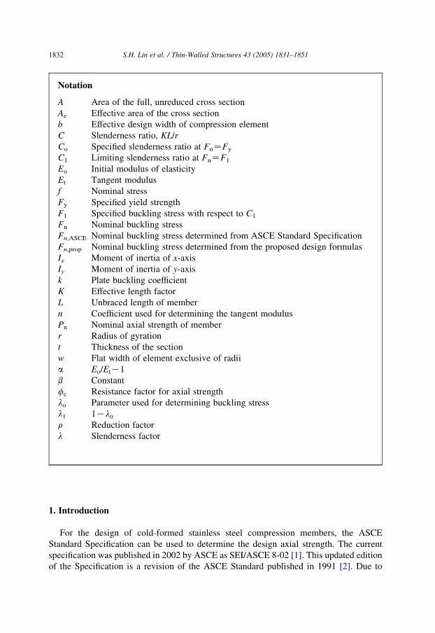
Notation
A Area of the full, unreduced cross section
Ae Effective area of the cross section
b Effective design width of compression element
C Slenderness ratio, KL/r
Co Specified slenderness ratio at FnZFy
C1 Limiting slenderness ratio at FnZF1
Eo Initial modulus of elasticity
Et Tangent modulus
f Nominal stress
Fy Specified yield strength
F1 Specified buckling stress with respect to C1
Fn Nominal buckling stress
Fn,ASCE Nominal buckling stress determined from ASCE Standard Specification
Fn,prop Nominal buckling stress determined from the proposed design formulas
Ix Moment of inertia of x-axis
Iy Moment of inertia of y-axis
k Plate buckling coefficient
K Effective length factor
L Unbraced length of member
n Coefficient used for determining the tangent modulus
Pn Nominal axial strength of member
r Radius of gyration
t Thickness of the section
w Flat width of element exclusive of radii
a Eo/EtK1
b Constant
fc Resistance factor for axial strength
lo Parameter used for determining buckling stress
l1 1Klo
r Reduction factor
l Slenderness factor
S.H. Lin et al. / Thin-Walled Structures 43 (2005) 1831–18511832
1. Introduction
For the design of cold-formed stainless steel compression members, the ASCE
Standard Specification can be used to determine the design axial strength. The current
specification was published in 2002 by ASCE as SEI/ASCE 8-02 [1]. This updated edition
of the Specification is a revision of the ASCE Standard published in 1991 [2]. Due to

a
b
cd
Str
ess
Strain
a Hot rolled carbon or low alloy steelb Cold rolled carbon low alloy steelc Annealed and flattened stainless steel
(longitudinal tension)d Annealed and flattened stainless steel (longitudinal compression)
Fig. 1. Stress–strain curves of carbon and stainless steels
S.H. Lin et al. / Thin-Walled Structures 43 (2005) 1831–1851 1833
the differences in mechanical behavior of stainless steels as compared with carbon steels as
shown in Fig. 1, the design of stainless steel compression members is more complex than
those of carbon steels. It is noted that stainless steels have gradually yielding type of
stress–strain curves with relatively low proportional limits [3,4]. Because of the nonlinear
stress-strain behavior, the design of stainless steel compression members is based on the
tangent modulus theory [5,6].
Stainless steel has different mechanical properties in longitudinal and transverse
directions for tension and compression modes of stress. As a result, different tangent
modulus, Et, are provided for different types of stainless steels in the design tables and
figures of the ASCE Specification. Tangent modulus is used to account for the inelastic
buckling of stainless steel compression components. Alternatively, it can be determined by
using the modified Ramberg–Osgood equation [7,8] given in Appendix B of the ASCE
Standard for specified types of stainless steels. Because of the nonlinear nature of tangent
modulus, the column buckling stress is determined through an iterative process until the
satisfied tolerance is reached [9,10]. This type of calculation is often tedious and time-
consuming as compared with that of hot-rolled steel column design.
To simplify the design process, this paper presents a new approach to obtain the design
formulas for determining the flexural buckling stress without successive iterations. These
formulas are developed from the tangent modulus equation obtained from the modified
Ramberg–Osgood equation. A mathematical approximating method utilizing the Taylor
series expansion theory is formulated for numerical approximation. New design formulas
are proposed for austenitic type of cold-formed stainless steel columns subjected to
flexural buckling. It is shown that the approximated solutions have a good agreement as
compared with the ASCE Standard solutions. To illustrate the simplified design approach,
a design example of cold-formed stainless steel column subjected to flexural buckling is
included in Appendix of the paper.

S.H. Lin et al. / Thin-Walled Structures 43 (2005) 1831–18511834
2. Review of ASCE design criteria
Section 3.4 of the ASCE Standard provides the design requirements to determine the
design axial strength for concentrically loaded cold-formed stainless steel compression
members. It specifies that the resultant of all loads acting on the members is an axial loads
passing through the centroid of the effective section calculated at the stress Fn. The design
axial strength, fcPn, is calculated as follows:
fc Z 0:85
Pn Z AeFn (1)
where:
AeZeffective area calculated at stress Fn
FnZthe least of the flexural, torsional, and torsional-flexural buckling stress
determined according to Sections 3.4.1–3.4.3 of the ASCE Standard, respectively.
Section 3.4.1 of the ASCE Standard specifies that, for doubly symmetric sections,
closed cross sections, and any other sections which are not subjected to torsional or
torsional–flexural buckling, the flexural buckling stress, Fn, is determined as follows:
Fn Zp2Et
ðKL=rÞ2%Fy (2)
where:
EtZtangent modulus in compression corresponding to buckling stress Fn
KL/rZslenderness ratio
FyZspecified yield strength, as given in Table 1 for austenitic type stainless steels
To calculate the flexural buckling stress in Eq. (2), it is necessary to have a proper value
of Et, which can be obtained from design tables or figures in the ASCE Standard for the
assumed stress. Alternatively, it can be determined by using analytical expression, which
is based on the modified Ramberg–Osgood equation
Et ZEoFy
Fy C0:002 nEoðFn=FyÞnK1
(3)
Table 1
ASCE specified yield strength Fy for austenitic type stainless steels [1]
Types of stress Fy, Mpa
Types 201, 301, 304, 316
Annealed 1/16 Hard 1/4 Hard 1/2Hard
Longitudinal
tension
206.9 310.3 517.1 758.5
Transverse tension 206.9 310.3 517.1 758.5
Transverse
compression
206.9 310.3 620.6 827.4
Longitudinal
compression
193.1 282.7 344.8 448.2

Table 2
ASCE specified initial modulus of elasticity Eo and coefficient n for austenitic type stainless steels [1]
Types of stress Types 201, 301, 304, 316
Annealed and1/16 Hard 1/4Hard 1/2Hard
Eo (MPa) n Eo (MPa) n Eo (MPa) n
Longitudinal tension 193100 8.31 186200 4.58 186200 4.21
Transverse tension 193100 7.78 193100 5.38 193100 6.71
Transverse compression 193100 8.63 193100 4.76 193100 4.54
Longitudinal
compression
193100 4.10 186200 4.58 186200 4.22
S.H. Lin et al. / Thin-Walled Structures 43 (2005) 1831–1851 1835
in which Eo is the initial modulus of elasticity and n is the coefficient used for determining
tangent modulus. Table 2 gives values of Eo and n for austenitic type stainless steels,
which are obtained from design tables in the ASCE Standard.
Because the buckling stress, Fn, and the tangent modulus, Et, are interdependent as self-
explanatory in Eqs. (2) and (3), the determination of flexural buckling stress, Fn, requires
iterative process. The buckling stress, Fn, is needed to determine Et in Eq. (3), but it is not
known until it has been obtained from Eq. (2). Therefore, to determine a proper value of Et,
a buckling stress is first to be assumed in Eq. (3). Then, this calculated value of Et is used to
determine the buckling stress, Fn, in Eq. (2). In view of the fact that the calculated buckling
stress is seldom equal to the first assumed buckling stress, further successive iterations are
needed to obtain the final buckling stress. This buckling stress can be achieved when a
satisfied convergence of error is reached.
For details of determining the buckling stress by using ASCE Standard design
provisions, see the design example in the appendix of the paper.
3. Simplified approach
As discussed above, for the design of cold-formed stainless steel columns, the
determination of flexural buckling stress is tiresome due to its iterative process of
calculation. As a result, a simplified approach is proposed herein to determine the flexural
buckling stress without having iterative calculations. New formulations are developed as
targets of the numerical approximation. In order to simplify the calculations, Taylor series
expansion is applied to the approximating equation. The following section gives detailed
presentations on this subject.
3.1. Initial concept
The flexural buckling stresses determined by using the ASCE design equations for
Type 304 stainless steel columns in longitudinal compression (LC) and transverse
compression (TC) are shown in Figs. 2 and 3, respectively. Nonlinear buckling stress
curves are found typical for those columns when the flexural buckling stresses are less than
Fy, which is the upper bond of Eq. (2). Thus, a linear equation is initialized in this study to
simplify these nonlinear curves.

0 50 100 150 200
Slenderness Ratio, KL/r
0
100
200
300
400
500
Fle
xura
l Buc
klin
g S
tres
s, F
n (M
Pa)
Type 304 Stainless Steel Columns(Longitudinal Compression)
Annealed1/16 Hard1/4 Hard1/2 Hard
Fig. 2. ASCE Standard flexural buckling stresses for Type 304 stainless steel columns in longitudinal
compression.
0 50 100 150 200Slenderness Ratio, KL/r
0
200
400
600
800
1000
Fle
xura
l Buc
klin
g S
tres
s, F
n (M
Pa)
Type 304 Stainless Steel Columns(Transverse Compression)
Annealed1/16 Hard1/4 Hard1/2 Hard
Fig. 3. ASCE Standard flexural buckling stresses for Type 304 stainless steel columns in transverse compression.
S.H. Lin et al. / Thin-Walled Structures 43 (2005) 1831–18511836
Slenderness Ratio, KL/r
Fle
xura
l Buc
klin
g S
tres
s in
Log
Sca
le, l
og F
n
Eq. (5)
Eq. (13)
A (C0 , logFy )
B ( C1, log F1 )log F1
C1C0
log Fy
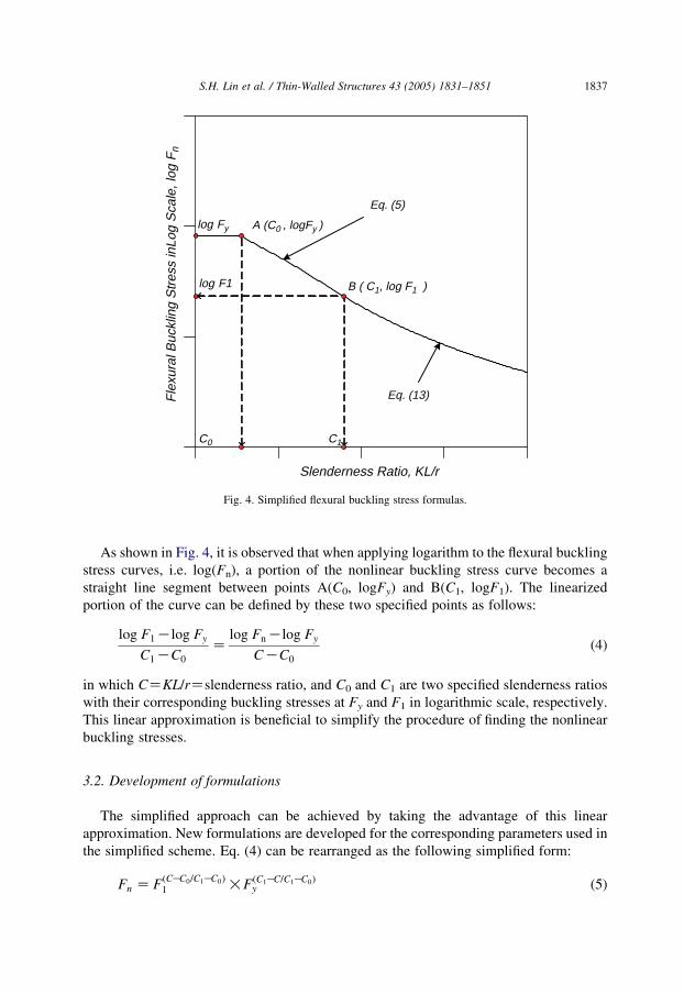
Fig. 4. Simplified flexural buckling stress formulas.
S.H. Lin et al. / Thin-Walled Structures 43 (2005) 1831–1851 1837
As shown in Fig. 4, it is observed that when applying logarithm to the flexural buckling
stress curves, i.e. log(Fn), a portion of the nonlinear buckling stress curve becomes a
straight line segment between points A(C0, logFy) and B(C1, logF1). The linearized
portion of the curve can be defined by these two specified points as follows:
log F1Klog Fy
C1KC0
Zlog FnKlog Fy
CKC0
(4)
in which CZKL/rZslenderness ratio, and C0 and C1 are two specified slenderness ratios
with their corresponding buckling stresses at Fy and F1 in logarithmic scale, respectively.
This linear approximation is beneficial to simplify the procedure of finding the nonlinear
buckling stresses.
3.2. Development of formulations
The simplified approach can be achieved by taking the advantage of this linear
approximation. New formulations are developed for the corresponding parameters used in
the simplified scheme. Eq. (4) can be rearranged as the following simplified form:
Fn Z FðCKC0=C1KC0Þ1 !FðC1KC=C1KC0Þ
y (5)

S.H. Lin et al. / Thin-Walled Structures 43 (2005) 1831–18511838
The parameters in the above equation can be obtained from the flexural buckling stress
equation in Eq. (2) and the tangent modulus equation in Eq. (3). As shown in Fig. 4, the
slenderness ratio of C0 in Eq. (5) is determined when Fn is equal to Fy. That is
Fn Z Fy Zp2Ey
ðKL=rÞ2(6)
r ðKL=rÞ2 Zp2Ey
Fy
Let
C0 Z KL=r Z p
ffiffiffiffiffiffiEy
Fy
sðfor Fn Z FyÞ (7)
where Ey is the tangent modulus at yield strength level and is equal to
Ey ZEo
1 C0:002 n Eo
Fy
(8)
The buckling stress F1 given in Eq. (5) is obtained from Eq. (3) by rearranging Et and Fn
and replacing Fn by F1 as follows:
F1 ZEoKEt
Et
� �Fy
0:002nEo
� �1=nK1
!Fy (9)
Let
a ZEoKEt
Et
ZEo
Et
K1 (10)
Then, Eq. (9) becomes
F1 ZaFy
0:002nE0
� �1=nK1
!Fy (11)
The value of F1 can be considered the proportional limit of stainless steels, which varies
with respect to the type of stainless steels.
Based on Eq. (10), the tangent modulus Et can be expressed in terms of a
Et ZEo
ð1 CaÞ(12)
Substitution of Eq. (12) into Eq. (2) yields the following general expression for the flexural
buckling stress:
Fn Zp2Et
ðKL=rÞ2Z
p2Eo
C2ð1 CaÞ(13)

S.H. Lin et al. / Thin-Walled Structures 43 (2005) 1831–1851 1839
Then, for the stress level at FnZF1, the limiting slenderness ratio of C1 can be obtained as
follows:
C1 Z p
ffiffiffiffiffiffiffiffiffiffiffiffiffiffiffiffiffiffiffiffiEo
F1ð1 CaÞ
sðfor Fn Z F1Þ (14)
The value of C1 can be considered a limiting slenderness ratio of column buckling as
shown in Fig. 4. When the KL/r ratio is greater than this limiting slenderness ratio, the
column buckling stress is calculated by Eq. (13); and when the KL/r ratio is smaller than
this limiting ratio, the column buckling stress is determined by Eq. (5).
3.3. Approximating expressions
The parameter a plays an important role in finding the buckling stress F1 in Eq. (11) and
the limiting slenderness ratio C1 in Eq. (14). When the a value is known, the determination
of buckling stress Fn in Eqs. (5) and (13) becomes straight forward without iterative
calculations. This section presents an approximating technique to evaluate the parameter aused in the equations of the proposed simplified approach.
The tangent modulus in Eq. (3) can be rewritten as
Et ZEoFy
Fy C0:002nEoðFn=FyÞnK1
ZEo
1 C0:002n Eo
Fy
� �Fn
Fy
� �nK1(15)
By comparing Eqs. (12) and (15), the parameter a can be expressed as
a Z 0:002nEo
Fy
� �Fn
Fy
� �nK1
(16)
Substituting the value of Fn in Eq. (13), Eq. (16) can be rewritten as
a Z 0:002nEo
Fny
� �p2Eo
C2ð1 CaÞ
� �nK1
(17)
From the above equation, it is noted that the parameter a can be combined to form a new
polynomial function as
f ðaÞ Z að1 CaÞnK1 Z 0:002np2
C2
� �nK1Eo
Fy
� �n
(18)
Eq. (18) is a function of a with degree of n (nZconstant coefficient, used for determining
tangent modulus as specified in ASCE Standard). Due to the complexity of the function,
approximating polynomial method is used to solve this equation. Therefore, Eq. (18) can
be approximately expressed by using Taylor series expansion as follows:
að1 CaÞnK1 ZXN
iZ0
f iðaÞ
i!ai C/ (19)
in which fi(a)is the ith derivative of the function f(a).

S.H. Lin et al. / Thin-Walled Structures 43 (2005) 1831–18511840
The correlation between both sides of Eq. (19) is carefully evaluated in order to obtain a
better approximated solution. Higher degrees of derivatives are neglected as common
engineering practice. Then, Eq. (19) can be approximately expressed as, for NZ2,
að1 CaÞnK1 ya C ðnK1Þa2 (20a)
and, for NZ3,
að1 CaÞnK1 ya C ðnK1Þa2 CðnK1ÞðnK2Þ
2a3 (20b)
Eqs. (20a) and (20b) are numerically evaluated for two specified n values as given in
Tables 3 and 4. These calculated values contain f(a)Za(1Ca)nK1,aC(nK1)a2, and aC(nK1)a2C(nK1)(nK2)a3/2 for a values varies from 0 to 0.2 at intervals of one-
hundredth. As compared with the actual values of f(a), the approximating values
calculated from Eq. (20b) provide better agreement than those calculated from Eq. (20a). It
is an obvious outcome for this typical series expansion, i.e. the more expanded terms are
used; the better approximation can be achieved. In this study, Eqs. (20a) and (20b) are
separately used to determine the a value for specified column buckling mode.
3.4. Numerical approximation
It is well known that, for columns having larger slenderness ratio, the elastic buckling
failure mode frequently controls the column strength. This buckling stress can be
Table 3
Comparisons of calculated values of Eqs. (20a) and (20b) for nZ4.58
a f(a)Za(1Ca)nK1 aC(nK1)a2aC ðnK1Þa2 C ððnK1Þ!
ðnK2Þ=2Þa3
0.00 0.00000 0.00000 0.00000
0.01 0.01036 0.01036 0.01036
0.02 0.02147 0.02143 0.02147
0.03 0.03335 0.03322 0.03335
0.04 0.04603 0.04573 0.04602
0.05 0.05954 0.05895 0.05953
0.06 0.07392 0.07289 0.07389
0.07 0.08919 0.08754 0.08913
0.08 0.10538 0.10291 0.10528
0.09 0.12253 0.11900 0.12236
0.10 0.14066 0.13580 0.14042
0.11 0.15983 0.15332 0.15946
0.12 0.18005 0.17155 0.17953
0.13 0.20136 0.19050 0.20065
0.14 0.22379 0.21017 0.22284
0.15 0.24739 0.23055 0.24614
0.16 0.27219 0.25165 0.27056
0.17 0.29823 0.27346 0.29615
0.18 0.32554 0.29599 0.32293
0.19 0.35417 0.31924 0.35091
0.20 0.38415 0.34320 0.38015

Table 4
Comparisons of calculated values of Eqs.(20a) and (20b) for nZ4.76
a f(a)Za(1Ca)nK1 aC(nK1)a2aC ðnK1Þa2 C ððnK1Þ!
ðnK2Þ=2Þa3
0.00 0.00000 0.00000 0.00000
0.01 0.01038 0.01038 0.01038
0.02 0.02155 0.02150 0.02155
0.03 0.03353 0.03338 0.03352
0.04 0.04636 0.04602 0.04635
0.05 0.06007 0.05940 0.06005
0.06 0.07470 0.07354 0.07466
0.07 0.09028 0.08842 0.09020
0.08 0.10685 0.10406 0.10672
0.09 0.12444 0.12046 0.12424
0.10 0.14310 0.13760 0.14279
0.11 0.16286 0.15550 0.16240
0.12 0.18376 0.17414 0.18311
0.13 0.20583 0.19354 0.20494
0.14 0.22913 0.21370 0.22793
0.15 0.25370 0.23460 0.25211
0.16 0.27956 0.25626 0.27751
0.17 0.30678 0.27866 0.30416
0.18 0.33539 0.30182 0.33209
0.19 0.36544 0.32574 0.36133
0.20 0.39696 0.35040 0.39191
S.H. Lin et al. / Thin-Walled Structures 43 (2005) 1831–1851 1841
determined by using Eq. (13) with a relatively small value of a. As noted in Tables 3 and 4,
the approximating values of aC(nK1)a2calculated in Eq. (20a) are very close to the
function values of f(a)Za(1Ca)nK1 when a value becomes smaller. Therefore, in this
case, Eq. (20a) is used to calculate the a value for numerical approximation. Thus, it
becomes
a C ðnK1Þa2 Z 0:002np2
C2
� �nK1Eo
Fy
� �n
(21)
This equation is a typical second order equation and can be solved by quadratic formula
a ZK1 C
ffiffiffiffiffiffiffiffiffiffiffiffiffiffiffiffiffiffiffiffiffiffiffiffiffiffiffiffiffiffiffiffiffiffiffiffiffiffiffiffiffiffiffiffiffiffiffiffiffiffiffiffiffiffiffiffiffiffiffiffiffiffiffiffiffi1 C4ðnK1Þ0:002n p2
C2
� �nK1Eo
Fy
� �nr
2ðnK1Þ(22)
This a is used for determining the buckling stress in Eq. (13) as shown in Fig. 4.
On the other hand, a relatively large a value is found to be needed for calculating the
buckling stress in the inelastic buckling mode. Because more accurate approximation is
needed for this case, Eq. (20b) is used to determine the value of a. However, this equation
cannot be solved with a simple formula. A reasonable estimation is needed to minimize the
error of the numerical approximation. It is tentatively recommended that the maximum
error between the approximating and actual values be limited to G0.3%. To meet this
convergence requirement, the following limitation is required:

S.H. Lin et al. / Thin-Walled Structures 43 (2005) 1831–18511842
ðnK1ÞðnK2Þa3=2
a C ðnK1Þa2%5% (23)
Assume that the maximum value of the parameter a determined from Eq. (23) is equal to
b. It yields
amax Z b Z1 C
ffiffiffiffiffiffiffiffiffiffiffiffiffiffiffiffiffiffiffiffiffiffiffi1 C 2ðnK2Þ
0:05ðnK1Þ
qnK2
!0:05 (24)
in which b is a constant, which depends only on the n value for different types of stainless
steels. This b value is the maximum value of a and is used to calculate the buckling stress
of F1 in Eq. (11) and the limiting slenderness ratio of C1 in Eq. (14).
4. Proposed design formulas
The flexural buckling stress of cold-formed stainless steel compression members can be
determined based on the above-mentioned simplified approach. By using the proposed
formulas, design calculation is no longer tedious because no iterative process is needed.
The following design provisions are proposed herein to determine the flexural buckling
stress, Fn, for austenitic types of cold-formed stainless steel compression members.
For doubly symmetric sections, closed cross sections, and any other sections which can
be shown not to be subjected to torsional or torsional–flexural buckling, the flexural
buckling stress, Fn, shall be determined as follows:
For KL/r%C1:
Fn Z Floy F
l1
1 %Fy (25)
For KL/rOC1:
Fn Zp2Eo
KLr
� 2ð1 CaÞ
(26)
where:
lo ZC1KKL=r
C1KCo
(27)
l1 Z 1Klo (28)
Co Z p
ffiffiffiffiffiffiEy
Fy
s(29)
C1 Z p
ffiffiffiffiffiffiffiffiffiffiffiffiffiffiffiffiffiffiffiffiEo
F1ð1 CbÞ
s(30)

S.H. Lin et al. / Thin-Walled Structures 43 (2005) 1831–1851 1843
Ey ZEo
1 C0:002n Eo
Fy
(31)
F1 Z Fy
bFy
0:002nEo
� �1=nK1
(32)
a ZK1 C
ffiffiffiffiffiffiffiffiffiffiffiffiffiffiffiffiffiffiffiffiffiffiffiffiffiffiffiffiffiffiffiffiffiffiffiffiffiffiffiffiffiffiffiffiffiffiffiffiffiffiffiffiffiffiffiffiffiffiffiffiffiffiffiffiffiffiffiffiffiffi1 C4ðnK1Þ0:002n p2
ðKL=rÞ2
h inK1Eo
Fy
� �nr
2ðnK1Þ(33)
b Z0:05 C
ffiffiffiffiffiffiffiffiffiffiffiffiffiffiffiffiffiffiffiffiffiffiffiffiffiffiffiffiffiffiffiffi0:0025 C 0:1ðnK2Þ
ðnK1Þ
qnK2
(34)
5. Comparisons and discussions
In this study, comparisons are made between the predicted flexural buckling stresses of
cold-formed stainless steel columns obtained from the ASCE Standard design equations
and the proposed simplified design formulas. Eqs. (2) and (3) are used for the ASCE
Standard predictions. The proposed design formulas provided in Section 4 of the paper are
used to determine the flexural buckling stresses. It shows that, without having iterative
calculations, the proposed equations give satisfactory predictions as compared with the
ASCE Standard results.
A commonly used Type 304, austenitic stainless steel column is used for the
comparison. The specified material properties of the column are previously given in
Table 2. The design parameters for the same materials determined from the proposed
design equations are listed in Table 5. For columns with this type of stainless steel, the
computed buckling stresses, Fn,ASCE and Fn,prop, and the ratios of Fn,prop/Fn,ASCE for
different slenderness ratios, KL/r, in longitudinal and transverse compression are given in
Tables 6 and 7, respectively. In these tables, Fn,ASCE and Fn,prop are predicted flexural
Table 5
Design parameters used in the proposed design formulas for type 304 stainless steels
Type of stress b C0 C1 F1 (MPa)
Longitudinal compression Annealed 0.1500 32.8 176.6 53.12
1/16 Hard 0.1500 32.0 137.3 87.94
1/4 Hard 0.1252 29.9 115.0 123.48
1/2 Hard 0.1429 30.2 98.4 165.91
Transverse compression Annealed 0.0526 23.2 136.1 97.72
1/16 Hard 0.0526 22.9 108.2 154.55
1/4 Hard 0.1179 27.8 80.5 259.62
1/2 Hard 0.1270 27.2 67.3 373.58

Table 6
Comparisons of flexural buckling stresses for type 304 stainless steel columns in longitudinal compression
Annealed 1/16 Hard 1/4 Hard 1/2 Hard
KL/r Fn,ASCE
(MPa)
Fn,prop
(MPa)
Fn,prop/
Fn,ASCE
Fn,ASCE
(MPa)
Fn,prop
(Mpa)
Fn,prop/
Fn,ASCE
Fn,ASCE
(MPa)
Fn,prop
(MPa)
Fn,prop/
Fn,ASCE
Fn,ASCE
(MPa)
Fn,prop
(MPa)
Fn,prop/
Fn,ASCE
20 193.1 193.1 1.00 282.7 282.7 1.00 344.4 344.5 1.00 448.2 448.2 1.00
40 173.4 181.0 1.04 249.1 258.6 1.04 296.3 305.4 1.03 378.5 388.4 1.03
60 137.4 151.2 1.10 193.7 207.2 1.07 232.1 239.9 1.03 283.4 290.3 1.02
80 114.2 126.4 1.11 156.7 166.0 1.06 186.0 188.4 1.01 215.6 217.0 1.01
100 96.9 105.6 1.09 128.4 133.0 1.04 148.2 148.0 1.00 162.2 161.5 1.00
120 82.9 88.3 1.07 105.0 106.5 1.01 116.0 115.7 1.00 121.3 121.3 1.00
140 71.0 73.8 1.04 85.5 85.1 1.00 90.1 90.1 1.00 91.8 91.8 1.00
160 60.7 61.7 1.02 69.4 69.4 1.00 70.6 70.6 1.00 71.1 71.1 1.00
180 51.7 51.5 1.00 56.7 56.6 1.00 56.3 56.3 1.00 56.5 56.5 1.00
200 44.0 43.9 1.00 46.7 46.7 1.00 45.8 45.8 1.00 45.8 45.8 1.00
AVG 1.05 1.02 1.01 1.01
COV 0.041 0.027 0.013 0.011
S.H. Lin et al. / Thin-Walled Structures 43 (2005) 1831–18511844
buckling stresses determined from the ASCE Standard and proposed design equations,
respectively.
Based on the results of comparison, it is observed that the proposed design formulas
predict slightly larger buckling stresses than those determined by the ASCE design
provisions for Type 304 annealed and 1/16 Hard stainless steel columns having medium
range of KL/r. The maximum ratio of Fn,prop/Fn,ASCE for annealed type is equal to 1.11 at
KL/rZ80, and for 1/16 Hard, the maximum ratio of Fn,prop/Fn,ASCE is equal to 1.07 at
KL/rZ60 as given in Table 6. These larger predictions of Fn,prop for annealed and 1/16
Hard types are mainly due to the relative low values of Fy and n specified in ASCE
Standard. However, for 1/4 Hard and 1/2 Hard, the proposed design formulas can provide
good predictions as compared with those obtained from the ASCE design equations. Their
Table 7
Comparisons of flexural buckling stresses for Type 304 stainless steel columns in transverse compression
Annealed 1/16 Hard 1/4 Hard 1/2 Hard
KL/r Fn,ASCE
(MPa)
Fn,prop
(MPa)
Fn,prop/
Fn,ASCE
Fn,ASCE
(MPa)
Fn,prop
(MPa)
Fn,prop/
Fn,ASCE
Fn,ASCE
(MPa)
Fn,prop
(MPa)
Fn,prop/
Fn,ASCE
Fn,ASCE
(MPa)
Fn,prop
(MPa)
Fn,prop/
Fn,ASCE
20 206.9 206.9 1.00 310.3 310.3 1.00 613.7 613.7 1.00 827.4 827.4 1.00
40 180.2 185.1 1.03 267.4 269.8 1.01 499.8 504.4 1.01 641.0 641.6 1.00
60 160.3 162.0 1.01 234.3 229.2 0.98 368.1 364.9 0.99 434.9 431.6 0.99
80 144.8 141.9 0.98 204.9 194.6 0.95 264.4 264.0 1.00 284.1 284.0 1.00
100 130.0 124.2 0.96 171.0 165.3 0.97 184.6 184.5 1.00 188.5 188.5 1.00
120 113.6 108.8 0.96 130.5 130.5 1.00 131.2 131.2 1.00 131.9 131.9 1.00
140 93.7 93.6 1.00 97.1 97.1 1.00 97.0 97.0 1.00 97.1 97.1 1.00
160 74.0 74.0 1.00 74.4 74.4 1.00 74.4 74.4 1.00 74.4 74.4 1.00
180 58.8 58.8 1.00 58.8 58.8 1.00 58.8 58.8 1.00 58.8 58.8 1.00
200 47.6 47.6 1.00 47.7 47.7 1.00 47.6 47.6 1.00 47.6 47.6 1.00
AVG 0.99 0.99 1.00 1.00
COV 0.023 0.019 0.004 0.003

0 50 100 150 200
Slenderness Ratio, KL/r
0
100
200
300
400
500
Fle
xura
l Buc
klin
g S
tres
s, F
n (M
Pa)
Type 304 Stainless Steel Columns(Longitudinal Compression)
Proposed (Annealed)Proposed (1/16Hard)Proposed (1/4Hard)Proposed (1/2Hard)ASCE (Annealed)ASCE (1/16Hard)ASCE (1/4Hard)ASCE (1/2Hard)
Fig. 5. Comparisons of flexural buckling stress curves in longitudinal compression.
S.H. Lin et al. / Thin-Walled Structures 43 (2005) 1831–1851 1845
maximum ratio of Fn,prop/Fn,ASCE is equal to 1.03 as given in Table 6. The computed
flexural buckling stresses versus slenderness ratios for Type 304 stainless steel columns,
annealed, 1/16 Hard, 1/4 Hard and 1/2 Hard in longitudinal compression, are also shown in
Fig. 5.
Table 7 gives predicted flexural buckling stresses and their corresponding stress
ratios for Type 304 stainless steels columns in transverse compression. It is found that
the proposed design equations provide good agreements with the ASCE design formulas
for annealed, 1/16 Hard, 1/4 Hard and 1/2 Hard types. The lowest ratio of Fn,prop/
Fn,ASCE for annealed type is equal to 0.96 at KL/rZ100 and 120, and for 1/16 Hard, the
lowest ratio of Fn,prop/Fn,ASCE is equal to 0.95 at KL/rZ80 as given in Table 7. For 1/4
Hard and 1/2 Hard, it is noted that the proposed design formulas provide good
predictions as compared with those obtained from the ASCE design equations. Fig. 6
shows the predicted flexural buckling stresses, Fn, versus the slenderness ratio, KL/r, for
Type 304 stainless steel columns, annealed, 1/16 Hard, 1/4 Hard and 1/2 Hard in
transverse compression.
To demonstrate the adequacy of proposed design formulas discussed above, a design
example is included in the appendix of the paper. It provides detailed calculations for
determining a cold-formed stainless steel column buckling strength by using the ASCE
Standard design equations and the proposed simplified formulas.

0 50 100 150 200Slenderness Ratio, KL/r
0
200
400
600
800
100
Fle
xura
l Buc
klin
g S
tres
s,F
n (M
Pa)
Type 304 Stainless Steel Columns(Transverse Compression)
Proposed (Annealed)Proposed (1/16 Hard)Proposed (1/4Hard)Proposed (1/2Hard)ASCE (Annealed)ASCE (1/16 Hard)ASCE (1/4 Hard)ASCE (1/2 Hard)
Fig. 6. Comparisons of flexural buckling stress curves in transverse compression.
S.H. Lin et al. / Thin-Walled Structures 43 (2005) 1831–18511846
6. Conclusions
For the design of cold-formed stainless steel compression members, the flexural
buckling stress is determined based on the tangent modulus theory. Because of the
nonlinear stress-strain behavior of the materials, the determination of flexural buckling
stress usually requires iterative process, which is often tedious and time-consuming for a
typical column design. In order to simplify the iterative calculation, newly developed
formulas utilizing the Taylor series expansion theory are proposed herein to determine
flexural buckling stress for austenitic type of cold-formed stainless steel columns. This
paper presents detailed derivations of the mathematical formulation and numerical
approximation. Comparisons are made between the predicted column flexural buckling
stresses determined from he ASCE design formulas and the proposed design equations. It
shows that the predicted flexural buckling stresses determined by the proposed design
equations are in good agreement with those calculated by the ASCE design formulas. The
proposed equations can be used as an alternative to determine the flexural buckling stress
for austenitic type of cold-formed stainless steel columns.
Acknowledgements
The financial support provided by the Minghsin University of Science and Technology
through the Project Number MUST 93-CE-006 is gratefully acknowledged.

S.H. Lin et al. / Thin-Walled Structures 43 (2005) 1831–1851 1847
Appendix. Design example
The following design example is to determine the design axial strength of a cold-
formed stainless steel column subjected to flexural buckling. The flexural buckling
stress used to calculate the design axial strength is determined by the following two
methods: (A) the design equations specified in the ASCE Standard Specification, and
(B) the proposed simplified design approach presented in the paper.
Given:
1. Square tube dimensions: 101.6 mm!101.6 mm!1.65 mm as shown in Fig. 7.
2. Sectional properties: AZ652.9 mm2, IxZIyZ1,081,369 mm4, rxZryZ40.7 mm.
3. Material properties: Type 304, 1/4-Hard stainless steel, FyZ344.8 MPa, EoZ186,
200 MPa and nZ4.58 in longitudinal compression.
4. Effective length: KxLxZKyLyZ3048 mm; and KxLx/rxZKyLy/ryZ74.9.
The sectional properties of square tubular section given above are determined by
using the information given in Part I of the AISI Cold-Formed Steel Design Manual
(2002) [11].
Solution:
101.6mm
101.
6mm
1.65mm
R=1.59
mm
w= 95.1mm
Sectional Properties: A = 652.9 mm2
Ix = Iy = 1081369 mm4
rx = ry = 40.7 mm
Effective Length:KxLx= KyLy = 3048 mm
Fig. 7. Square tube used for design example.

S.H. Lin et al. / Thin-Walled Structures 43 (2005) 1831–18511848
(A). The ASCE standard specification
The square tube is a doubly symmetric closed section, which is not subjected to
torsional or torsional-flexural buckling. The flexural buckling stress, Fn, can be determined
by Equation 3.4.1K1 of the ASCE Standard as given in Eq. (2) above. The tangent
modulus Et used for this example is determined by using the Modified Ramberg–Osgood
equation as given in Eq. (3). Due to the nature of the iterative process, try-and-error
calculations are necessary to determine the buckling stress, Fn.
For the first try, assume a buckling stress of FnZ230 MPa and its corresponding
tangent modulus in Eq. (3) is calculated as
Et Z ð186200!344:8Þ=½344:8 C0:002!4:58!186200!ð230=344:8Þ3:58�
y86167 MPa
Thus, the computed buckling stress in Eq. (2) is equal to
ðFnÞ1 Z ðp2 !86167Þ=ð74:9Þ2 Z 151:6 MPa!assumed buckling stress 230 MPa
ðN:G:Þ
Because the computed buckling stress is not close enough to the assumed value, further
iteration is needed.
For the second try, it is assumed that FnZ191 MPa. The corresponding tangent
modulus becomes
Et Z ð186200!344:8Þ=½344:8 C0:002!4:58!186200!ð191=344:8Þ3:58�
y116599 MPa
The computed buckling stress is equal to
ðFnÞ2 Z ðp2 !116599Þ=ð74:9Þ2 Z 205:1 MPaOassumed buckling stress 191 MPa
ðN:G:Þ
For the third try, it is assumed that FnZ198.1 MPa. The corresponding tangent modulus is
calculated as follows:
Et Z ð186200!344:8Þ=½344:8 C0:002!4:58!186200!ð198:1=344:8Þ3:58�
y110817 MPa
The computed buckling stress is
ðFnÞ3 Z ðp2 !110817Þ=ð74:9Þ2 Z 195:0 MPa! assumed stress 198:1 MPaðN:G:Þ
The buckling stress is repeatedly assumed until it reaches the minimum convergence to the
calculated value. After several try-and-error iterations, a buckling stress of FnZ

S.H. Lin et al. / Thin-Walled Structures 43 (2005) 1831–1851 1849
196.8 MPa is obtained, and the tangent modulus is calculated as
Et Z ð186200!344:8Þ=½344:8 C0:002!4:58 �186200!ð196:8=344:8Þ3:58�
y111872 MPa
Thus, the buckling stress is equal to
Fn Z ðp2 !111872Þ=ð74:9Þ2 Z 196:8 MPa ðO:K:Þ
To determine the effective area of the member, the design provisions of Section 2.2 in the
ASCE Standard are used to calculate the effective widths of flanges and webs of the tubular
section. Based on the results of calculation, it is found that the flanges and webs of the
section are not fully effective. The effective area of the tubular section is calculated in
accordance with the ASCE Standard provisions as follows:
k Z 4:0; f Z Fn Z 196:8 MPa
l Z1:052ffiffiffi
kp
� �w
t
� � ffiffiffiffiffiffif
Eo
s !Z 1:052=
ffiffiffiffiffiffiffi4:0
p� �ð95:1=1:65Þ
ffiffiffiffiffiffiffiffiffiffiffiffiffiffiffiffiffiffiffiffiffiffiffiffiffiffiffi196:8=186200
p
Z 0:986O0:673 (A1)
r Z1K0:22=l
lZ ð1K0:22=0:986Þ=0:986 Z 0:788 (A2)
b Z rw Z 0:788!95:1 Z 75:2 mm (A3)
Ae Z AK4ðwKbÞt Z 652:9K4ð95:1K75:2Þ!1:65 Z 521:6 mm2
The design axial strength, fcPn, is determined from Eq. (1) as
fc Z 0:85; Pn Z Ae Fn Z 521:6!196:8 Z 102651 N Z 102:7 kN
ðfcPnÞASCE Z 0:85!102:7 Z 87:3 kN
(B). The proposed simplified approach
By using the proposed design formulas presented in Section 4 of this paper, the flexural
buckling stress of cold-formed stainless steel column can be easily calculated without
iterations.
(1) Calculate the design parameters:
Design parameters used in this example are calculated from the proposed formulas as
follows:
b Z0:05 C
ffiffiffiffiffiffiffiffiffiffiffiffiffiffiffiffiffiffiffiffiffiffiffiffiffiffiffiffiffiffiffiffiffiffiffiffi0:0025 C 0:1ð4:58K2Þ
ð4:58K1Þ
q4:58K2
Z 0:1252

S.H. Lin et al. / Thin-Walled Structures 43 (2005) 1831–18511850
Ey Z186200
1 C0:002!4:58! 186200344:8
Z 31312 MPa
Co Z p
ffiffiffiffiffiffiffiffiffiffiffiffiffi31312
344:8
rZ 29:9
F1 Z 344:80:1252!344:8
0:002!4:58!186200
� �1=4:58K1
Z 123:5 MPa
C1 Z p
ffiffiffiffiffiffiffiffiffiffiffiffiffiffiffiffiffiffiffiffiffiffiffiffiffiffiffiffiffiffiffiffiffiffiffiffiffi186200
123:5ð1 C0:1252Þ
sZ 115
(2) Calculate the flexural buckling stress:
Since the column slenderness ratio KL/rZ74.9!C1, the flexural buckling stress is
determined from Eq. (25) as follows:
Fn Z Floy F
l1
1 %Fy
where:
lo ZC1KKL=r
C1KCo
Z115K74:9
115K29:9Z 0:471; and l1 Z 1 lo Z 0:529
Thus,
Fn Z 344:80:471 !123:50:529 Z 200:3 MPa
(3) Determine the effective area:
The effective area of the tubular section is calculated as follows:
k Z 4:0; f Z Fn Z 200:3 MPa
l Z1:052ffiffiffi
kp
� �w
t
� � ffiffiffiffiffiffif
Eo
s !Z 1:052=
ffiffiffiffiffiffiffi4:0
p� �ð95:1=1:65Þ
ffiffiffiffiffiffiffiffiffiffiffiffiffiffiffiffiffiffiffiffiffiffiffiffiffiffiffi200:3=186200
p
Z 0:994O0:673
r Z1K0:22=l
lZ ð1K0:22=0:994Þ=0:994 Z 0:783
b Z rw Z 0:783!95:1 Z 74:5 mm
Ae Z AK4ðwKbÞt Z 652:9K4ð95:1K74:5Þ!1:65 Z 516:9 mm2

S.H. Lin et al. / Thin-Walled Structures 43 (2005) 1831–1851 1851
(4) Find the design axial strength:
The design axial strength, fcPn, is determined as follows:
fc Z 0:85; Pn Z Ae Fn Z 516:9!200:3 Z 103535 N Z 103:5 kN
ðfPnÞprop: Z 0:85!103:5 Z 88:0 kN
This design example provides detailed calculations to determine the design axial strength
for a typical cold-formed stainless steel tubular column. Two methods are used in this
example: (A) the ASCE Standard design equations and (B) the proposed design formulas
presented herein. There is no iterative calculation used in the proposed design formulas.
The flexural buckling stress calculated from the proposed design formulas is easier than
that determined from ASCE Standard design equations. For this design example, the
design axial strength determined by using the proposed design formulas is 0.8% larger
than that found by using the design equations stipulated in the ASCE Standard.
References
[1] Specification for the design of cold-formed stainless steel structural members, (SEI/ASCE 8-02), American
Society of Civil Engineers (ASCE); 2002.
[2] Specification for the design of cold-formed stainless steel structural members, (ANSI/ASCE 8-90),
American Society of Civil Engineers (ASCE); 1991.
[3] Johnson AL, Kelsen GA. Stainless steel in structural applications, stainless steel for architecture. American
Society for Testing and Materials, STP 454; Aug. 1969.
[4] Yu WW. Cold-formed steel design. New York, NY: Wiley–Interscience; 2000.
[5] Johnston BG, editor. Guide to stability design criteria for metal structures. 3rd ed. New York, NY: Wiley;
1976.
[6] Galambos TV. Structural members and frames. Englewood Cliffs, NJ: Prentice-Hall; 1968.
[7] Ramberg W, Osgood WR. Description of stress-strain curves by three parameters. NACA technical note,
No. 902; July 1943.
[8] Hill HN. Determination of stress–strain relations from offset yield strength values. NACA tech. note, No.
927; Feb 1944.
[9] Rasmussen KJR, Rondal J. Column curves for stainless steel alloys. J Construct Steel Res 2000;54:89–107.
[10] Rasmussen KJR, Rondal J. Explicit approach to design of stainless steel columns. J Struct Eng Am Soc Civil
Eng 1997;123(7):857–63.
[11] Cold-formed steel design manual. Washington, DC: American Iron and Steel Institute; 2002.