PERFORMANCE OF LOCALLY PRODUCED COLD ... OF LOCALLY PRODUCED COLD-FORMED STEEL SECTIONS 13 2.0 THE...
17
Jurnal Teknologi, 42(B) Jun. 2005: 11–28 © Universiti Teknologi Malaysia 1,2&3 Steel Technology Centre, Faculty of Civil Engineering, Universiti Teknologi Malaysia, 81310 Skudai, Johor, Malaysia. PERFORMANCE OF LOCALLY PRODUCED COLD-FORMED STEEL SECTIONS FOR ROOF TRUSS SYSTEM MAHMOOD M. T 1 , THONG, C. M. 2 & TAN, C. S. 3 Abstract. Traditionally, timber is usually used for roof truss as a construction material. However, the use of timber is no longer popular recently due to the increase in cost, not environmental- friendly as more trees need to be cut, prone to termite attack, and lesser capacity compared with steel. Cold-formed steel section has been introduced in this paper for the construction of roof truss system as an alternative to timber truss. This paper describes experimental test results of the proposed cold-formed produced locally with the code of practice as prescribed by BS 5950 Part 5: 1987 for the use in roof truss system. The tests were also performed to meet the requirements that have been outlined by Public Works Department, Malaysia. The experimental results showed good agreement with BS 5950 Part 5. From the study it can be concluded that the proposed locally produced cold-formed steel sections and the connections are suitable to be used in the roof truss system provided that the design values should not be more than the experimental values. Keywords: Cold-formed steel section, roof truss system, section capacities, C-section, hat-section Abstrak. Secara tradisi kayu biasanya digunakan untuk kekuda bumbung sebagai bahan binaan. Walau bagaimanapun, kegunaan kayu tidak lagi mendapat sambutan kebelakangan ini disebabkan kos yang tinggi, bukan mesra alam sekitar disebabkan banyak pokok perlu ditebang, terdedah kepada serangan anai-anai dan keupayaan yang rendah dibandingkan dengan keluli. Keratan keluli terguling-sejuk telah dicadangkan di dalam kertas ini bagi pembinaan sistem bumbung kekuda sebagai pilihan lain daripada kekuda kayu. Kertas ini membincangkan keputusan uji kaji bagi cadangan keratan keluli terguling-sejuk yang dikeluarkan oleh pengeluar tempatan sebagaimana yang dinyatakan di dalam kod BS5950 Part 5:1987 bagi kegunaan sistem kekuda bumbung. Ujian- ujian ini juga adalah untuk menepati keperluan-keperluan yang telah digariskan oleh Jabatan Kerja Raya Malaysia. Keputusan-keputusan ujian dari uji kaji menunjukkan keputusan persetujuan yang baik dengan BS 5950 Part 5. Keputusan uji kaji merumuskan bahawa keratan keluli terguling sejuk keluaran tempatan dan sambungannya sesuai digunakan bagi sistem kekuda bumbung. Kata kunci: Keratan keluli terguling-sejuk, sistem kekuda bumbung, keupayaan keratan, keratan C, keratan topi 1.0 INTRODUCTION The use of light gauge construction material has been recently highlighted by Public Works Department Malaysia, especially in replacing wood for roof truss system in school buildings. Therefore, cold-formed steel section, which has been proven to be Untitled-126 02/17/2007, 00:45 11
Transcript of PERFORMANCE OF LOCALLY PRODUCED COLD ... OF LOCALLY PRODUCED COLD-FORMED STEEL SECTIONS 13 2.0 THE...
PERFORMANCE OF LOCALLY PRODUCED COLD-FORMED STEEL SECTIONS 11
Jurnal Teknologi, 42(B) Jun. 2005: 11–28© Universiti Teknologi Malaysia
1,2&3Steel Technology Centre, Faculty of Civil Engineering, Universiti Teknologi Malaysia, 81310Skudai, Johor, Malaysia.
PERFORMANCE OF LOCALLY PRODUCED COLD-FORMEDSTEEL SECTIONS FOR ROOF TRUSS SYSTEM
MAHMOOD M. T1, THONG, C. M.2 & TAN, C. S.3
Abstract. Traditionally, timber is usually used for roof truss as a construction material. However,the use of timber is no longer popular recently due to the increase in cost, not environmental-friendly as more trees need to be cut, prone to termite attack, and lesser capacity compared withsteel. Cold-formed steel section has been introduced in this paper for the construction of roof trusssystem as an alternative to timber truss. This paper describes experimental test results of theproposed cold-formed produced locally with the code of practice as prescribed by BS 5950 Part 5:1987 for the use in roof truss system. The tests were also performed to meet the requirements thathave been outlined by Public Works Department, Malaysia. The experimental results showedgood agreement with BS 5950 Part 5. From the study it can be concluded that the proposed locallyproduced cold-formed steel sections and the connections are suitable to be used in the roof trusssystem provided that the design values should not be more than the experimental values.
Keywords: Cold-formed steel section, roof truss system, section capacities, C-section, hat-section
Abstrak. Secara tradisi kayu biasanya digunakan untuk kekuda bumbung sebagai bahan binaan.Walau bagaimanapun, kegunaan kayu tidak lagi mendapat sambutan kebelakangan ini disebabkankos yang tinggi, bukan mesra alam sekitar disebabkan banyak pokok perlu ditebang, terdedahkepada serangan anai-anai dan keupayaan yang rendah dibandingkan dengan keluli. Keratankeluli terguling-sejuk telah dicadangkan di dalam kertas ini bagi pembinaan sistem bumbungkekuda sebagai pilihan lain daripada kekuda kayu. Kertas ini membincangkan keputusan uji kajibagi cadangan keratan keluli terguling-sejuk yang dikeluarkan oleh pengeluar tempatan sebagaimanayang dinyatakan di dalam kod BS5950 Part 5:1987 bagi kegunaan sistem kekuda bumbung. Ujian-ujian ini juga adalah untuk menepati keperluan-keperluan yang telah digariskan oleh JabatanKerja Raya Malaysia. Keputusan-keputusan ujian dari uji kaji menunjukkan keputusan persetujuanyang baik dengan BS 5950 Part 5. Keputusan uji kaji merumuskan bahawa keratan keluli tergulingsejuk keluaran tempatan dan sambungannya sesuai digunakan bagi sistem kekuda bumbung.
Kata kunci: Keratan keluli terguling-sejuk, sistem kekuda bumbung, keupayaan keratan, keratanC, keratan topi
1.0 INTRODUCTION
The use of light gauge construction material has been recently highlighted by PublicWorks Department Malaysia, especially in replacing wood for roof truss system inschool buildings. Therefore, cold-formed steel section, which has been proven to be
Untitled-126 02/17/2007, 00:4511
MAHMOOD M. T, THONG, C.M. & TAN, C.S.12
efficient and widely used in developed countries, is a good alternative to traditionaltimber truss system. Manufacturers have started to develop new industrial-networksystem to elaborate the process from manufacturing to construction stage while someof them still import existing technology from abroad. The need for roof truss systemusing cold-formed section have shown tremendous increase in demand in Malaysiadue to the policy changes that require the use of cold-formed steel sections for rooftruss system by Public Works Department for most of the government projects. Inorder to fulfil the technical and performance requirements which have been set bythe Public Works Department, a collaborative testing project is carried out by SteelTechnology Centre, Universiti Teknologi Malaysia, and Tong Yong Private Limited.The Steel Technology Centre provides technical and expert support in implementingthe testing, verification, analysis and design of the proposed cold-formed steel sectionfor the roof truss system.
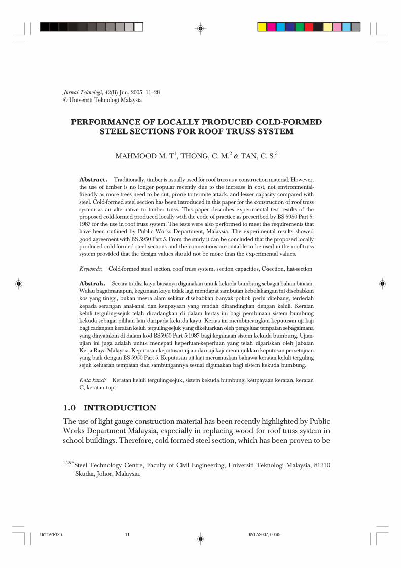
Cold-formed steel is a steel product that is formed by a steel strip or sheet ofuniform thickness, in cold state. The cold-formed steel section, which is regarded assteel strip with uniform profile along its length, is usually used in load bearingapplication [1]. The use of cold-formed steel section can be found in automobileindustry, shipbuilding, rail transport, and construction industry. In buildingconstruction, the cold-formed steel is utilised in both non-structural and structuralmembers. As non-structural members, the advantages are more on rust resistanceand aesthetic purposes. It is used as non-structural member for wall panelling,doorframes, window frames, and services. As structural members, the usage includesroof sheeting, purlins, truss members, beams, columns, and floor decking in steel-concrete composite construction. Figure 1 shows a typical model of roof truss systemformed with cold-formed steel section. A pointed screw system using a hand drill isnormally used for the installation of the connections.
Figure 1 Model of cold-formed steel roof truss system
Untitled-126 02/17/2007, 00:4512
PERFORMANCE OF LOCALLY PRODUCED COLD-FORMED STEEL SECTIONS 13
2.0 THE ADVANTAGES OF COLD-FORMED STEEL SECTION
Generally, cold-formed steel sections have several advantages over hot rolled steelsections and timber trusses. The main advantages are listed as follows [2,3]:
2.1 No Insect and Fungal Infection
The problems such as rot and discomposition due to insect and fungal infections areeliminated. Therefore, the material curing and maintenance costs, which are necessaryfor timber, could be eliminated as well.
2.2 Consistency and Accuracy of Profile
The nature of manufacturing process of cold rolling includes the ability of the desiredprofile to be maintained and repeated for as long as required with minimumtolerances. The consistency and accuracy of the profile can easily be achieved bythe use of computer control system. The quality of the section can be efficientlycontrolled in the factory, and does not depend on environmental factor as in thecase of timber.
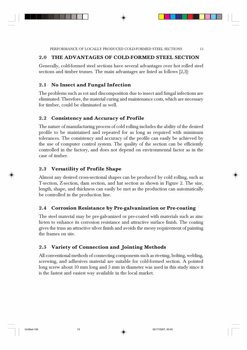
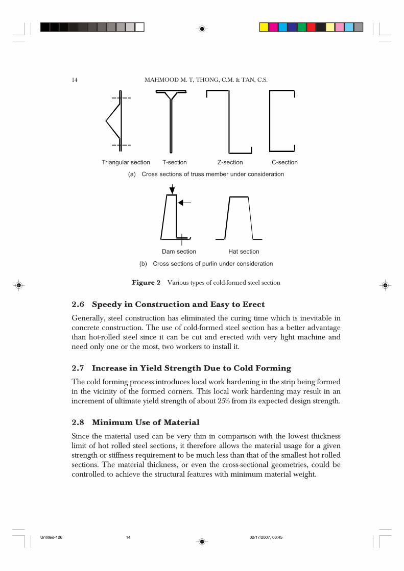
2.3 Versatility of Profile Shape
Almost any desired cross-sectional shapes can be produced by cold rolling, such asT-section, Z-section, dam section, and hat section as shown in Figure 2. The size,length, shape, and thickness can easily be met as the production can automaticallybe controlled in the production line.
2.4 Corrosion Resistance by Pre-galvanization or Pre-coating
The steel material may be pre-galvanized or pre-coated with materials such as zinchi-ten to enhance its corrosion resistance and attractive surface finish. The coatinggives the truss an attractive silver finish and avoids the messy requirement of paintingthe frames on site.
2.5 Variety of Connection and Jointing Methods
All conventional methods of connecting components such as riveting, bolting, welding,screwing, and adhesives material are suitable for cold-formed section. A pointedlong screw about 10 mm long and 5 mm in diameter was used in this study since itis the fastest and easiest way available in the local market.
Untitled-126 02/17/2007, 00:4513
MAHMOOD M. T, THONG, C.M. & TAN, C.S.14
2.6 Speedy in Construction and Easy to Erect
Generally, steel construction has eliminated the curing time which is inevitable inconcrete construction. The use of cold-formed steel section has a better advantagethan hot-rolled steel since it can be cut and erected with very light machine andneed only one or the most, two workers to install it.
2.7 Increase in Yield Strength Due to Cold Forming
The cold forming process introduces local work hardening in the strip being formedin the vicinity of the formed corners. This local work hardening may result in anincrement of ultimate yield strength of about 25% from its expected design strength.
2.8 Minimum Use of Material
Since the material used can be very thin in comparison with the lowest thicknesslimit of hot rolled steel sections, it therefore allows the material usage for a givenstrength or stiffness requirement to be much less than that of the smallest hot rolledsections. The material thickness, or even the cross-sectional geometries, could becontrolled to achieve the structural features with minimum material weight.
Figure 2 Various types of cold-formed steel section
Triangular section T-section Z-section C-section
Dam section Hat section
(a) Cross sections of truss member under consideration
(b) Cross sections of purlin under consideration
Untitled-126 02/17/2007, 00:4514
PERFORMANCE OF LOCALLY PRODUCED COLD-FORMED STEEL SECTIONS 15
2.9 Lower in Production Cost and Higher in Profit
In cold rolled process, the manufacturing costs involve the purchasing of the rollingmachine and the steel strip coils. The cost of the machine can be easily recovered inthe continuous mass production of the section. The cold formed steel roof trusssystem, which is in great demand and not enough supply locally can be consideredas having a good potential as a construction material. Therefore, the investmentrequired is relatively lower and the return back is sooner than most of otherconstruction materials.
3.0 DEVELOPMENT OF THE SECTIONS AND CONNECTIONS
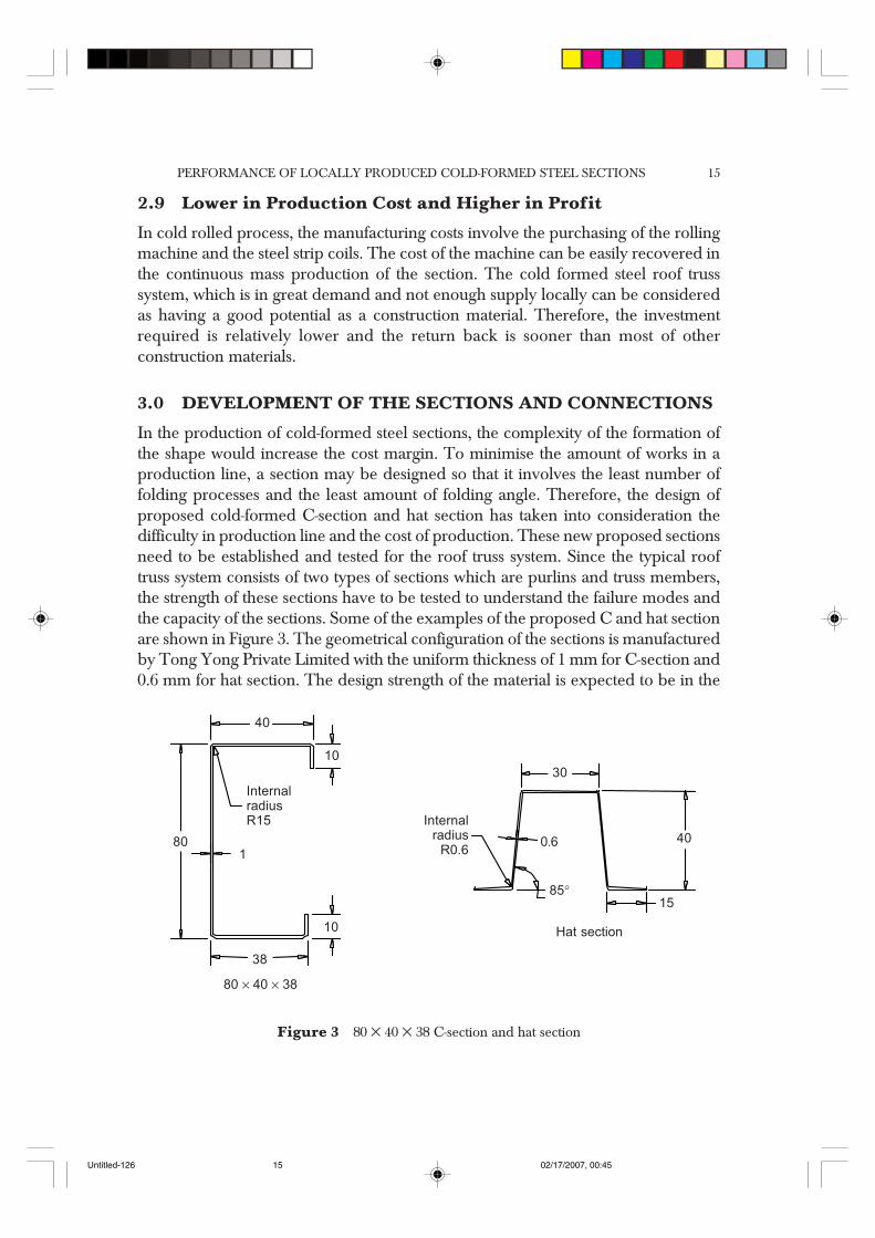
In the production of cold-formed steel sections, the complexity of the formation ofthe shape would increase the cost margin. To minimise the amount of works in aproduction line, a section may be designed so that it involves the least number offolding processes and the least amount of folding angle. Therefore, the design ofproposed cold-formed C-section and hat section has taken into consideration thedifficulty in production line and the cost of production. These new proposed sectionsneed to be established and tested for the roof truss system. Since the typical rooftruss system consists of two types of sections which are purlins and truss members,the strength of these sections have to be tested to understand the failure modes andthe capacity of the sections. Some of the examples of the proposed C and hat sectionare shown in Figure 3. The geometrical configuration of the sections is manufacturedby Tong Yong Private Limited with the uniform thickness of 1 mm for C-section and0.6 mm for hat section. The design strength of the material is expected to be in the
Figure 3 80 × 40 × 38 C-section and hat section
40
80 × 40 × 38
38
10
1
InternalradiusR15
80
10
30
40
15
0.6
85°
Internalradius
R0.6
Hat section
Untitled-126 02/17/2007, 00:4515
MAHMOOD M. T, THONG, C.M. & TAN, C.S.16
range of 250 to 300 N/mm2. The C-section is designed for tension, compression,and bending force in roof truss. For the top chord of the roof truss, the member bentdue to the loading of purlin between the nodes in the truss system. Both analyticaland experimental approaches were carried out in the study. The method of analysingthe strength of the cold-formed was based on BS5950: Part 5:1987 [5]. Experimentalwork involved testing of the individual capacities of the cold-formed section fortension, compression, bending and dynamic which are discussed later in the paper.
The cold-formed sections were connected together to form members of roof trusssystem by a group of screws that are formed as connection. The arrangement ofscrews to form connection can be classified into a group of two and four number ofscrews. These connections need to be tested for their capacity in shear, tension, andbearing. A cordless drill was used to install the screws to connect the designatedsection. However, the thickness of the connected section should not be more than 2mm as a more powerful drill may be needed to install the screw.
4.0 ANALYTICAL ANALYSIS
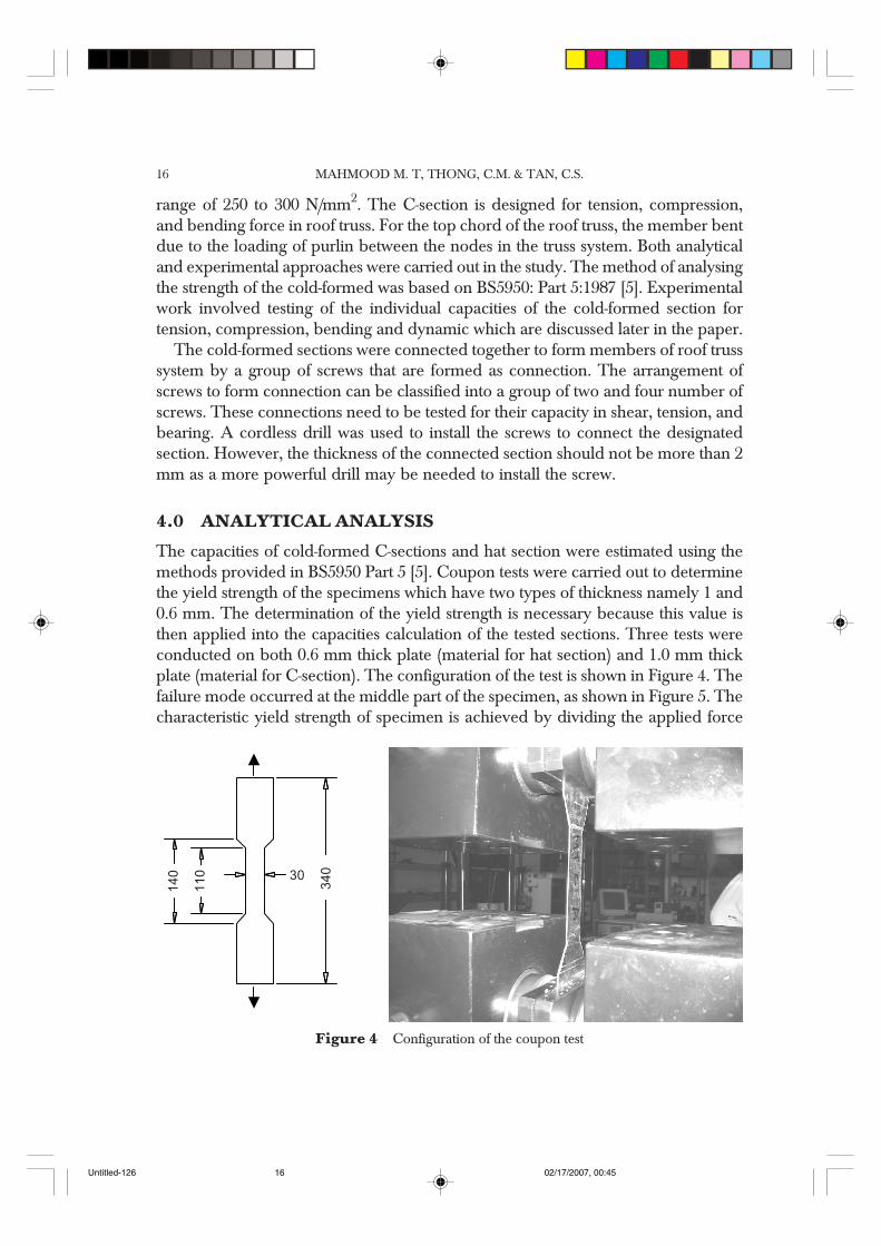
The capacities of cold-formed C-sections and hat section were estimated using themethods provided in BS5950 Part 5 [5]. Coupon tests were carried out to determinethe yield strength of the specimens which have two types of thickness namely 1 and0.6 mm. The determination of the yield strength is necessary because this value isthen applied into the capacities calculation of the tested sections. Three tests wereconducted on both 0.6 mm thick plate (material for hat section) and 1.0 mm thickplate (material for C-section). The configuration of the test is shown in Figure 4. Thefailure mode occurred at the middle part of the specimen, as shown in Figure 5. Thecharacteristic yield strength of specimen is achieved by dividing the applied force
Figure 4 Configuration of the coupon test
14
0 30
11
0
34
0
Untitled-126 02/17/2007, 00:4516
PERFORMANCE OF LOCALLY PRODUCED COLD-FORMED STEEL SECTIONS 17
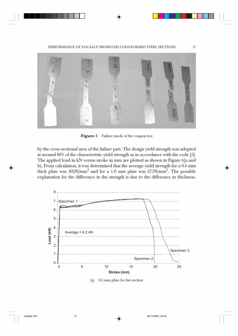
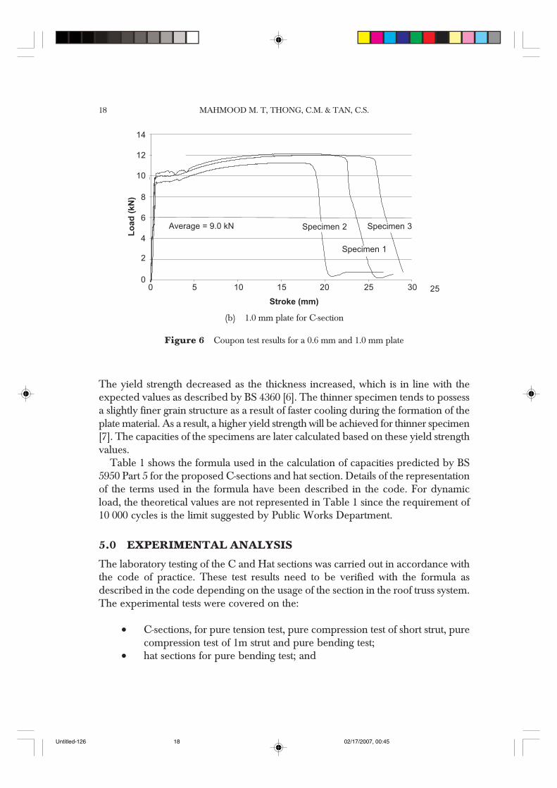
by the cross sectional area of the failure part. The design yield strength was adoptedat around 85% of the characteristic yield strength as in accordance with the code [5].The applied load in kN versus stroke in mm are plotted as shown in Figure 6(a andb). From calculation, it was determined that the average yield strength for a 0.6 mmthick plate was 302N/mm2 and for a 1.0 mm plate was 275N/mm2. The possibleexplanation for the difference in the strength is due to the difference in thickness.
Figure 5 Failure mode of the coupon test
6.2kN
(a) 0.6 mm plate for hat section
8
10500
1
2
3
4
5
6
7 Specimen 1
Average = 6.2 kN
15 20 25
Specimen 2
Specimen 3
Stroke (mm)
Lo
ad
(kN
)
Untitled-126 02/17/2007, 00:4517
MAHMOOD M. T, THONG, C.M. & TAN, C.S.18
The yield strength decreased as the thickness increased, which is in line with theexpected values as described by BS 4360 [6]. The thinner specimen tends to possessa slightly finer grain structure as a result of faster cooling during the formation of theplate material. As a result, a higher yield strength will be achieved for thinner specimen[7]. The capacities of the specimens are later calculated based on these yield strengthvalues.
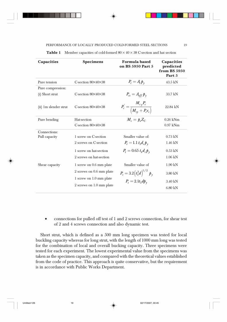
Table 1 shows the formula used in the calculation of capacities predicted by BS5950 Part 5 for the proposed C-sections and hat section. Details of the representationof the terms used in the formula have been described in the code. For dynamicload, the theoretical values are not represented in Table 1 since the requirement of10 000 cycles is the limit suggested by Public Works Department.
5.0 EXPERIMENTAL ANALYSIS
The laboratory testing of the C and Hat sections was carried out in accordance withthe code of practice. These test results need to be verified with the formula asdescribed in the code depending on the usage of the section in the roof truss system.The experimental tests were covered on the:
• C-sections, for pure tension test, pure compression test of short strut, purecompression test of 1m strut and pure bending test;
• hat sections for pure bending test; and
0
9.0kN
10500
2
4
6
8
10
12
14
Average = 9.0 kN
15 20 25
Specimen 2
Stroke (mm)
Lo
ad
(kN
)
Specimen 1
Specimen 3
25 30
(b) 1.0 mm plate for C-section
Figure 6 Coupon test results for a 0.6 mm and 1.0 mm plate
Untitled-126 02/17/2007, 00:4518
PERFORMANCE OF LOCALLY PRODUCED COLD-FORMED STEEL SECTIONS 19
Table 1 Member capacities of cold-formed 80 × 40 × 38 C-section and hat section
Capacities Specimens Formula based Capacitieson BS 5950 Part 5 predicted
from BS 5950Part 5
Pure tension C-section 80×40×38 =t t yP A p 43.5 kN
Pure compression:
(i) Short strut C-section 80×40×38 =cs eff yP A p 33.7 kN
(ii) 1m slender strut C-section 80×40×38 ( )=
+c cy'
ccy c s
M PP
M P e22.84 kN
Pure bending Hat-section =c o CM p Z 0.26 kNm
C-section 80×40×38 0.97 kNm
Connections:Pull capacity 1 screw on C-section Smaller value of: 0.73 kN
2 screws on C-section = 31 1t s yP . t d p 1.46 kN
1 screw on hat-section = 40 65t s yP . t d p 0.53 kN
2 screws on hat-section 1.06 kN
Shear capacity 1 screw on 0.6 mm plate Smaller value of 1.90 kN
2 screws on 0.6 mm plate ( )=1 23
33 2/
s yP . t d p 3.80 kN1 screw on 1.0 mm plate
= 32 1s yP . t dp 3.40 kN2 screws on 1.0 mm plate
6.80 kN
• connections for pulled off test of 1 and 2 screws connection, for shear testof 2 and 4 screws connection and also dynamic test.
Short strut, which is defined as a 500 mm long specimen was tested for localbuckling capacity whereas for long strut, with the length of 1000 mm long was testedfor the combination of local and overall bucking capacity. Three specimens weretested for each experiment. The lowest experimental value from the specimens wastaken as the specimen capacity, and compared with the theoretical values establishedfrom the code of practice. This approach is quite conservative, but the requirementis in accordance with Public Works Department.
Untitled-126 02/17/2007, 00:4519
MAHMOOD M. T, THONG, C.M. & TAN, C.S.20
5.1 Pure Tension Test
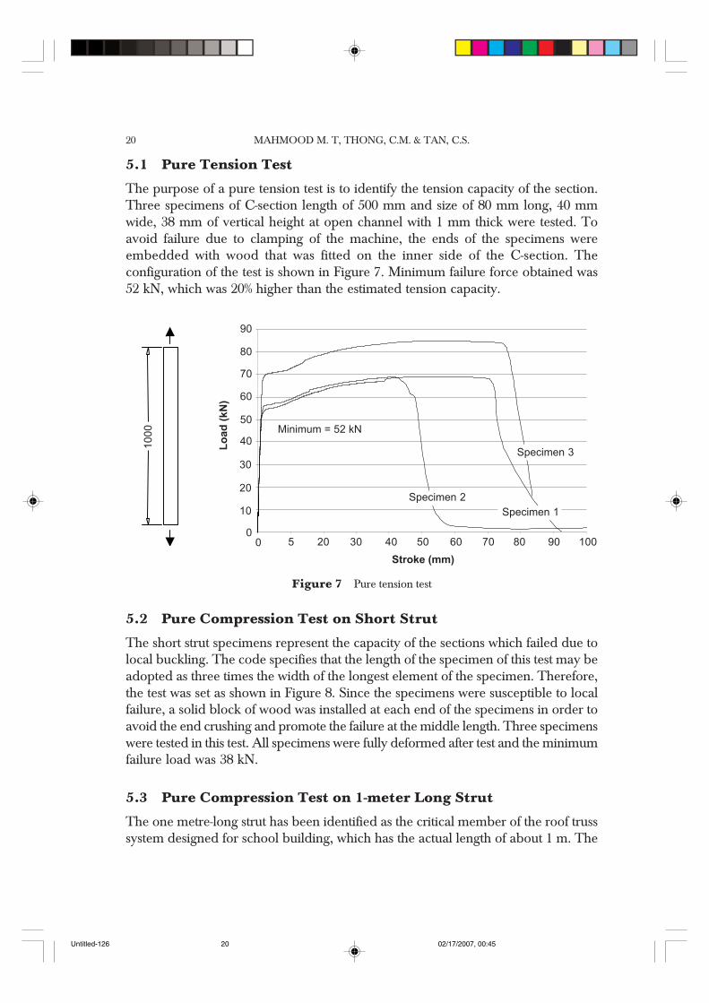
The purpose of a pure tension test is to identify the tension capacity of the section.Three specimens of C-section length of 500 mm and size of 80 mm long, 40 mmwide, 38 mm of vertical height at open channel with 1 mm thick were tested. Toavoid failure due to clamping of the machine, the ends of the specimens wereembedded with wood that was fitted on the inner side of the C-section. Theconfiguration of the test is shown in Figure 7. Minimum failure force obtained was52 kN, which was 20% higher than the estimated tension capacity.
52kN
Minimum = 52kN
Specimen 2 Specimen 1
Specimen 3
Figure 7 Pure tension test
30500
10
20
30
40
50
80
90
Minimum = 52 kN
4020 70
Specimen 2
Stroke (mm)
Lo
ad
(kN
)
Specimen 1
Specimen 3
50 60
70
60
80 90 100
5.2 Pure Compression Test on Short Strut
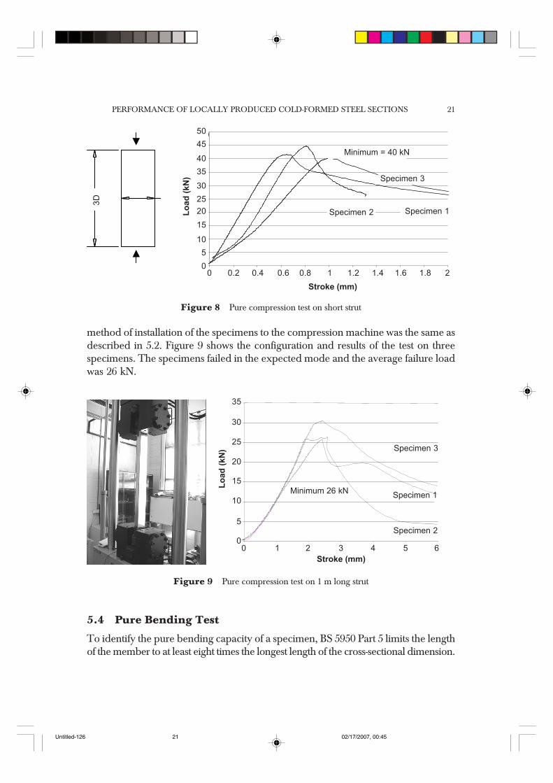
The short strut specimens represent the capacity of the sections which failed due tolocal buckling. The code specifies that the length of the specimen of this test may beadopted as three times the width of the longest element of the specimen. Therefore,the test was set as shown in Figure 8. Since the specimens were susceptible to localfailure, a solid block of wood was installed at each end of the specimens in order toavoid the end crushing and promote the failure at the middle length. Three specimenswere tested in this test. All specimens were fully deformed after test and the minimumfailure load was 38 kN.
5.3 Pure Compression Test on 1-meter Long Strut
The one metre-long strut has been identified as the critical member of the roof trusssystem designed for school building, which has the actual length of about 1 m. The
10
00
Untitled-126 02/17/2007, 00:4520
PERFORMANCE OF LOCALLY PRODUCED COLD-FORMED STEEL SECTIONS 21
method of installation of the specimens to the compression machine was the same asdescribed in 5.2. Figure 9 shows the configuration and results of the test on threespecimens. The specimens failed in the expected mode and the average failure loadwas 26 kN.
0
38kN
Specimen 1
Minimum = 40kN
Specimen 2
Specimen 3
45
0.40.200
15
20
25
30
40
50
35
Specimen 1
Minimum = 40 kN
0.6 10.8
Specimen 2
Specimen 3
Stroke (mm)
Lo
ad
(kN
)
10
5
1.41.2 1.81.6 2
Figure 8 Pure compression test on short strut
2100
15
20
25
30
35
Specimen 1Minimum 26 kN
3 54
Specimen 2
Specimen 3
Stroke (mm)
Lo
ad
(kN
)
10
5
6
Figure 9 Pure compression test on 1 m long strut
5.4 Pure Bending Test
To identify the pure bending capacity of a specimen, BS 5950 Part 5 limits the lengthof the member to at least eight times the longest length of the cross-sectional dimension.
3D
Untitled-126 02/17/2007, 00:4521
MAHMOOD M. T, THONG, C.M. & TAN, C.S.22
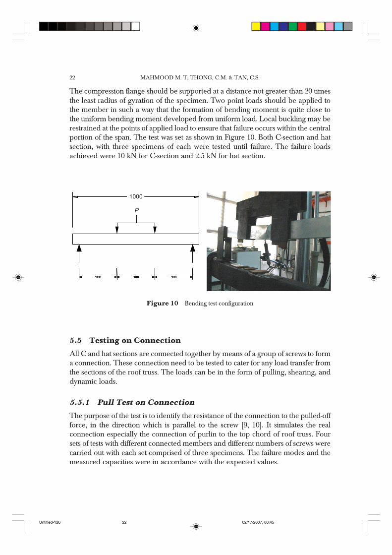
The compression flange should be supported at a distance not greater than 20 timesthe least radius of gyration of the specimen. Two point loads should be applied tothe member in such a way that the formation of bending moment is quite close tothe uniform bending moment developed from uniform load. Local buckling may berestrained at the points of applied load to ensure that failure occurs within the centralportion of the span. The test was set as shown in Figure 10. Both C-section and hatsection, with three specimens of each were tested until failure. The failure loadsachieved were 10 kN for C-section and 2.5 kN for hat section.
P
Figure 10 Bending test configuration
5.5 Testing on Connection
All C and hat sections are connected together by means of a group of screws to forma connection. These connection need to be tested to cater for any load transfer fromthe sections of the roof truss. The loads can be in the form of pulling, shearing, anddynamic loads.
5.5.1 Pull Test on Connection
The purpose of the test is to identify the resistance of the connection to the pulled-offforce, in the direction which is parallel to the screw [9, 10]. It simulates the realconnection especially the connection of purlin to the top chord of roof truss. Foursets of tests with different connected members and different numbers of screws werecarried out with each set comprised of three specimens. The failure modes and themeasured capacities were in accordance with the expected values.
1000
P
Untitled-126 02/17/2007, 00:4522
PERFORMANCE OF LOCALLY PRODUCED COLD-FORMED STEEL SECTIONS 23
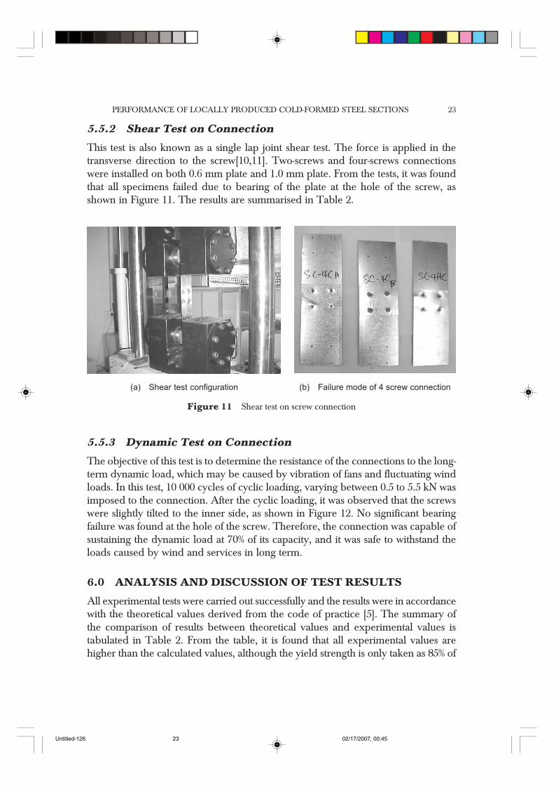
5.5.2 Shear Test on Connection
This test is also known as a single lap joint shear test. The force is applied in thetransverse direction to the screw[10,11]. Two-screws and four-screws connectionswere installed on both 0.6 mm plate and 1.0 mm plate. From the tests, it was foundthat all specimens failed due to bearing of the plate at the hole of the screw, asshown in Figure 11. The results are summarised in Table 2.
(a) Shear test configuration (b) Failure mode of 4 screw connection
Figure 11 Shear test on screw connection
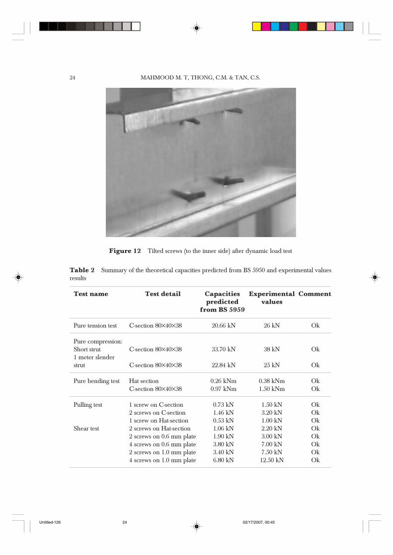
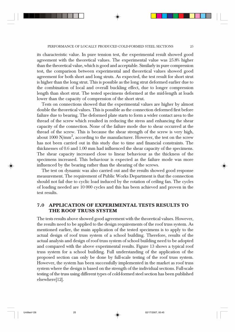
5.5.3 Dynamic Test on Connection
The objective of this test is to determine the resistance of the connections to the long-term dynamic load, which may be caused by vibration of fans and fluctuating windloads. In this test, 10 000 cycles of cyclic loading, varying between 0.5 to 5.5 kN wasimposed to the connection. After the cyclic loading, it was observed that the screwswere slightly tilted to the inner side, as shown in Figure 12. No significant bearingfailure was found at the hole of the screw. Therefore, the connection was capable ofsustaining the dynamic load at 70% of its capacity, and it was safe to withstand theloads caused by wind and services in long term.
6.0 ANALYSIS AND DISCUSSION OF TEST RESULTS
All experimental tests were carried out successfully and the results were in accordancewith the theoretical values derived from the code of practice [5]. The summary ofthe comparison of results between theoretical values and experimental values istabulated in Table 2. From the table, it is found that all experimental values arehigher than the calculated values, although the yield strength is only taken as 85% of
Untitled-126 02/17/2007, 00:4523
MAHMOOD M. T, THONG, C.M. & TAN, C.S.24
Figure 12 Tilted screws (to the inner side) after dynamic load test
Table 2 Summary of the theoretical capacities predicted from BS 5950 and experimental valuesresults
Test name Test detail Capacities Experimental Commentpredicted values
from BS 5959
Pure tension test C-section 80×40×38 20.66 kN 26 kN Ok
Pure compression:Short strut C-section 80×40×38 33.70 kN 38 kN Ok1 meter slenderstrut C-section 80×40×38 22.84 kN 25 kN Ok
Pure bending test Hat section 0.26 kNm 0.38 kNm OkC-section 80×40×38 0.97 kNm 1.50 kNm Ok
Pulling test 1 screw on C-section 0.73 kN 1.50 kN Ok2 screws on C-section 1.46 kN 3.20 kN Ok1 screw on Hat-section 0.53 kN 1.00 kN Ok
Shear test 2 screws on Hat-section 1.06 kN 2.20 kN Ok2 screws on 0.6 mm plate 1.90 kN 3.00 kN Ok4 screws on 0.6 mm plate 3.80 kN 7.00 kN Ok2 screws on 1.0 mm plate 3.40 kN 7.50 kN Ok4 screws on 1.0 mm plate 6.80 kN 12.50 kN Ok
Untitled-126 02/17/2007, 00:4524
PERFORMANCE OF LOCALLY PRODUCED COLD-FORMED STEEL SECTIONS 25
its characteristic value. In pure tension test, the experimental result showed goodagreement with the theoretical values. The experimental value was 25.8% higherthan the theoretical value, which is good and acceptable. Similarly in pure compressiontest, the comparison between experimental and theoretical values showed goodagreement for both short and long struts. As expected, the test result for short strutis higher than the long strut. This is possible as the long strut deformed earlier due tothe combination of local and overall buckling effect, due to longer compressionlength than short strut. The tested specimens deformed at the mid-length at loadslower than the capacity of compression of the short strut.
Tests on connections showed that the experimental values are higher by almostdouble the theoretical values. This is possible as the connection deformed first beforefailure due to bearing. The deformed plate starts to form a wider contact area to thethread of the screw which resulted in reducing the stress and enhancing the shearcapacity of the connection. None of the failure mode due to shear occurred at thethread of the screw. This is because the shear strength of the screw is very high,about 1000 N/mm2, according to the manufacturer. However, the test on the screwhas not been carried out in this study due to time and financial constraints. Thethicknesses of 0.6 and 1.00 mm had influenced the shear capacity of the specimens.The shear capacity increased close to linear behaviour as the thickness of thespecimens increased. This behaviour is expected as the failure mode was moreinfluenced by the bearing rather than the shearing of the screws.
The test on dynamic was also carried out and the results showed good responsemeasurement. The requirement of Public Works Department is that the connectionshould not fail due to cyclic load induced by the rotation of ceiling fan. The cyclesof loading needed are 10 000 cycles and this has been achieved and proven in thetest results.
7.0 APPLICATION OF EXPERIMENTAL TESTS RESULTS TOTHE ROOF TRUSS SYSTEM
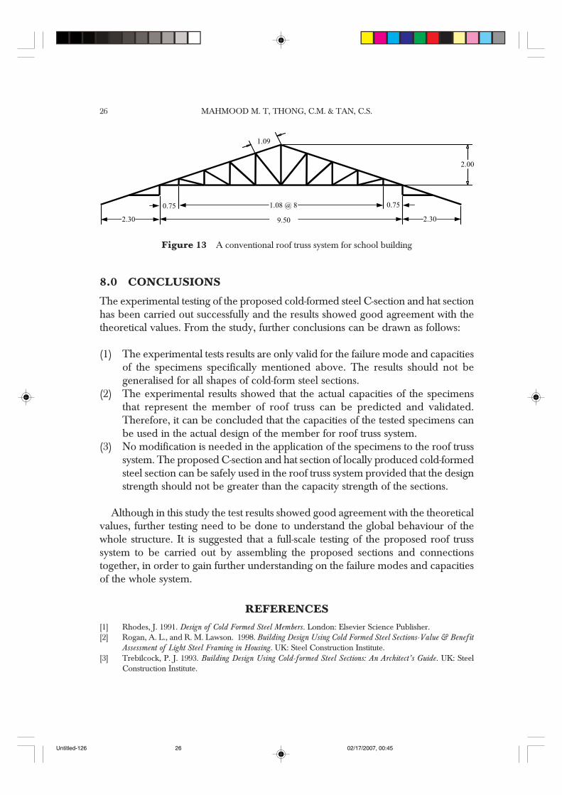
The tests results above showed good agreement with the theoretical values. However,the results need to be applied to the design requirements of the roof truss system. Asmentioned earlier, the main application of the tested specimens is to apply to theactual design of roof truss system of a school building. Therefore, results of theactual analysis and design of roof truss system of school building need to be adoptedand compared with the above experimental results. Figure 13 shows a typical rooftruss system for a school building. Full understanding of the application of theproposed section can only be done by full-scale testing of the roof truss system.However, the system has been successfully implemented in the market as roof trusssystem where the design is based on the strength of the individual sections. Full-scaletesting of the truss using different types of cold-formed steel section has been publishedelsewhere[12].
Untitled-126 02/17/2007, 00:4525
MAHMOOD M. T, THONG, C.M. & TAN, C.S.26
8.0 CONCLUSIONS
The experimental testing of the proposed cold-formed steel C-section and hat sectionhas been carried out successfully and the results showed good agreement with thetheoretical values. From the study, further conclusions can be drawn as follows:
(1) The experimental tests results are only valid for the failure mode and capacitiesof the specimens specifically mentioned above. The results should not begeneralised for all shapes of cold-form steel sections.
(2) The experimental results showed that the actual capacities of the specimensthat represent the member of roof truss can be predicted and validated.Therefore, it can be concluded that the capacities of the tested specimens canbe used in the actual design of the member for roof truss system.
(3) No modification is needed in the application of the specimens to the roof trusssystem. The proposed C-section and hat section of locally produced cold-formedsteel section can be safely used in the roof truss system provided that the designstrength should not be greater than the capacity strength of the sections.
Although in this study the test results showed good agreement with the theoreticalvalues, further testing need to be done to understand the global behaviour of thewhole structure. It is suggested that a full-scale testing of the proposed roof trusssystem to be carried out by assembling the proposed sections and connectionstogether, in order to gain further understanding on the failure modes and capacitiesof the whole system.
REFERENCES[1] Rhodes, J. 1991. Design of Cold Formed Steel Members. London: Elsevier Science Publisher.[2] Rogan, A. L., and R. M. Lawson. 1998. Building Design Using Cold Formed Steel Sections-Value & Benefit
Assessment of Light Steel Framing in Housing. UK: Steel Construction Institute.[3] Trebilcock, P. J. 1993. Building Design Using Cold-formed Steel Sections: An Architect’s Guide. UK: Steel
Construction Institute.
1.08@8
1.09
1.08 @ 8
9.50
0.75 0.75
2.30 2.30
2.00
Figure 13 A conventional roof truss system for school building
Untitled-126 02/17/2007, 00:4526
PERFORMANCE OF LOCALLY PRODUCED COLD-FORMED STEEL SECTIONS 27
[4] Grubb, P. J., and R. M. Lawson. 1997. Building Design Using Cold-formed Steel Sections: ConstructionDetailing and Practice. UK: Steel Construction Institute.
[5] British Standard Institute 1987. British Standard: Structural Use of Steelwork in Building, Part 5. Code ofPractice for Design of Cold Formed Sections. London: BS5950 Part 5: 1987
[6] British Standards Institute. 1986. BS 4360. Specification for Weldable Structural Steels.[7] Nethercot, D. A. 1991. Limit States Design of Structural Steelwork, Second Edition. 2-6 Boundary Row,
London SE1 8HN: Chapman & Hall.[8] European Convention for Constructional Steelwork. 1983. The Design and Testing of Connections in Steel
Sheeting and Sections. London: ECCS-TC7. Publication No. 21.[9] European Convention for Constructional Steelwork. 1983. Mechanical Fasteners for use in Steel Sheeting
and Sections. London: ECCS-TC7. Publication No. 35.[10] Olli K., J. Kesti, and P. Makelainen. 2001. The Behaviour of a New Type of Connection System for Light-
weight Steel Structures Applied to Roof Trusses. Techno-press: Steel and Composite Structures. 1(1): 17-32.[11] Thong, C. M. 2003. Development of New Cold-formed Steel Sections for Roof Truss System. Master
Thesis. Universiti Teknologi Malaysia.[12] Tahir, M. Md., S. Saad, A. L. Saleh, and C. K. Tan. 2003. Full-Scale Testing for Roof Truss System Using
Cold-Formed Steel Sections. Easec Asia Structural Engineering Conference EASEC09 Bali. Indonesion.16-18 Dec.
Untitled-126 02/17/2007, 00:4527