Simon Assembly Instructions Nathan Seidle : nathan ...the iron and the solder bridge. Hold still for...
5
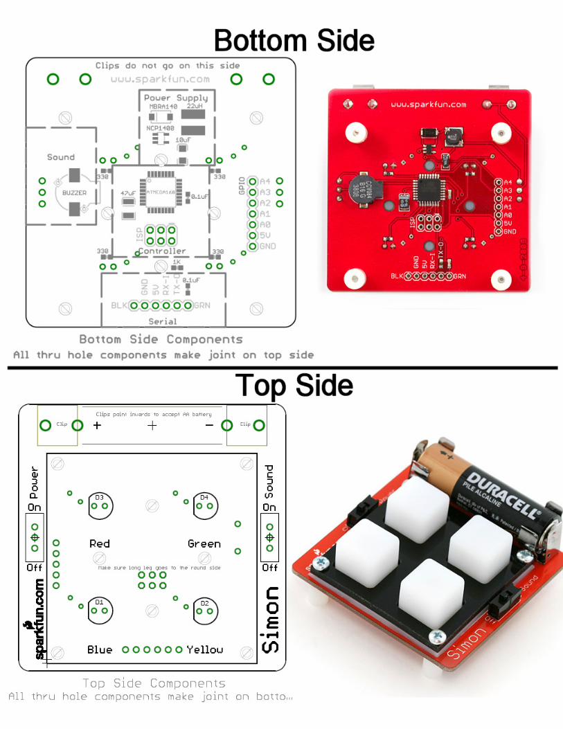
Simon Assembly Instructions Step Name Purpose Side Polarized? Marking Power Supply 1 NCP1400 DC to DC Step up Bottom No Make sure to line it up with pads on board 2 22uH Inductor Bottom No Make sure the pads on the inductor line up with pads on board 3 MBRA140 Diode Bottom Yes Line on diode matches line on silkscreen 4 47uF Tantalum Cap Bottom Yes Line on capacitor goes on rounded end of silkscreen 5 10uF Tantalum Cap Bottom Yes Line on capacitor goes on rounded end of silkscreen 6 Power Switch Top No Keep iron tip away! Plastic melts easy 7 Clip x 2 Battery Holder Top Yes Before proceeding – insert AA battery and test output voltage. Should be 5V. Remove battery before proceeding Controller 8 ATmega168 Bottom Yes Corner of IC has small circle on top side – matches silkscreen circle 9 0.1uF x 2 IC decoupling Bottom No In general, ceramic caps are not polarized and do not have an up/down 10 1K Resistor Reset pull-up Bottom No In general, resistors are not polarized but have a label on the top side 10 330 x 4 LED limiter Bottom No In general, resistors are not polarized but have a label on the top side 11 LED Top Yes Sound 12 Sound Switch Top No Keep iron tip away! Plastic melts easy 13 Buzzer Sound Bottom Yes + on buzzer matches silkscreen Mechanical 14 Button pad Buttons Top No 15 Stand offs Stand offs No Once assembled – bring to Matt or Nathan for programming Nathan Seidle : [email protected] Matt Bolton : [email protected] Push hard! Make sure the clips are pushed flat against the PCB. Make sure clips point towards each other to accept AA battery. Microcontroller LEDs Red – Green – Blue – Yellow LED housing *may not* match the silkscreen. Make sure the long leg of the LED goes into the hole next to the round side of the silkscreen indicator. Lay rubber pad over LEDs. Lay black frame on top rubber pad. Insert 4 screws through frame. Attach 4 stand offs to screws. Hold screw in place and twist stand off onto screw. Once assembled – Test that there is not continuity between pins labeled 5V and GND.
Transcript of Simon Assembly Instructions Nathan Seidle : nathan ...the iron and the solder bridge. Hold still for...

Simon Assembly Instructions
Step Name Purpose Side Polarized? Marking
Power Supply
1 NCP1400 DC to DC Step up Bottom No Make sure to line it up with pads on board2 22uH Inductor Bottom No Make sure the pads on the inductor line up with pads on board3 MBRA140 Diode Bottom Yes Line on diode matches line on silkscreen4 47uF Tantalum Cap Bottom Yes Line on capacitor goes on rounded end of silkscreen5 10uF Tantalum Cap Bottom Yes Line on capacitor goes on rounded end of silkscreen6 Power Switch Top No Keep iron tip away! Plastic melts easy
7 Clip x 2 Battery Holder Top Yes
Before proceeding – insert AA battery and test output voltage. Should be 5V.Remove battery before proceeding
Controller8 ATmega168 Bottom Yes Corner of IC has small circle on top side – matches silkscreen circle9 0.1uF x 2 IC decoupling Bottom No In general, ceramic caps are not polarized and do not have an up/down10 1K Resistor Reset pull-up Bottom No In general, resistors are not polarized but have a label on the top side
10 330 x 4 LED limiter Bottom No In general, resistors are not polarized but have a label on the top side
11 LED Top Yes
Sound12 Sound Switch Top No Keep iron tip away! Plastic melts easy13 Buzzer Sound Bottom Yes + on buzzer matches silkscreen
Mechanical14 Button pad Buttons Top No
15 Stand offs Stand offs No
Once assembled – bring to Matt or Nathan for programming
Nathan Seidle : [email protected]
Matt Bolton : [email protected]
Push hard! Make sure the clips are pushed flat against the PCB. Make sure clips point towards each other to accept AA battery.
Microcontroller
LEDs
Red – Green – Blue – Yellow
LED housing *may not* match the silkscreen. Make sure the long leg of the LED goes into the hole next to the round side of the silkscreen indicator.
Lay rubber pad over LEDs. Lay black frame on top rubber pad.
Insert 4 screws through frame. Attach 4 stand offs to screws. Hold screw in place and twist stand off onto screw.
Once assembled – Test that there is not continuity between pins labeled 5V and GND.

Soldering Workshop Review
Rating: 1 (bad) 2 3 4 5 6 7 8 9 10 (great)
How long did it take you to complete the kit?
What did you like best?
What did you like least?
Comments:
Date of workshop:
What other instructional workshops would you like to see (PCB layout, microcontrollers, etc)?
SMD Soldering Workshop
1 © 2008 www.sparkfun.com
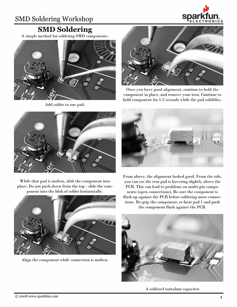
SMD Soldering A simple method for soldering SMD components.
Add solder to one pad.
While that pad is molten, slide the component into place. Do not push down from the top - slide the com-
ponent into the blob of solder horizontally.
Align the component while connection is molten.
Once you have good alignment, continue to hold the component in place, and remove your iron. Continue to hold component for 1-2 seconds while the pad solidifies.
From above, the alignment looked good. From the side, you can see the rear pad is hovering slightly above the PCB. This can lead to problems on multi-pin compo-nents (open connections). Be sure the component is
flush up against the PCB before soldering more connec-tions. Re-grip the component, re-heat pad 1 and push
the component flush against the PCB.
A soldered tantalum capacitor
SMD Soldering Workshop
2 © 2008 www.sparkfun.com
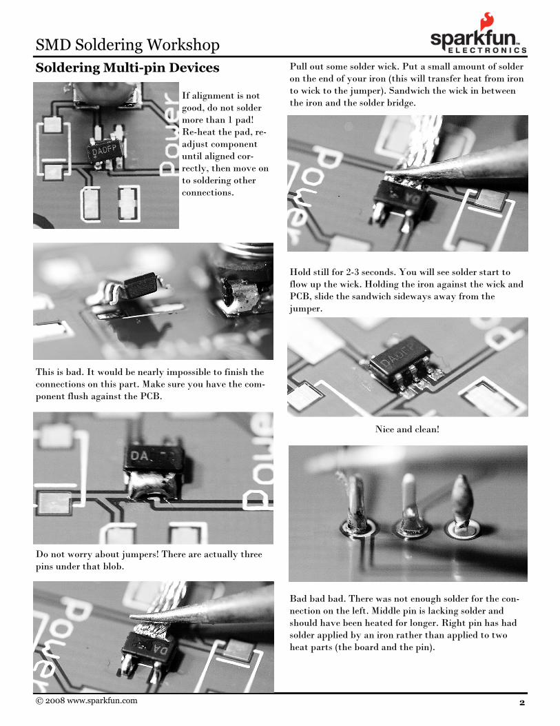
Soldering Multi-pin Devices If alignment is not good, do not solder more than 1 pad! Re-heat the pad, re-adjust component until aligned cor-rectly, then move on to soldering other connections.
This is bad. It would be nearly impossible to finish the connections on this part. Make sure you have the com-ponent flush against the PCB.
Do not worry about jumpers! There are actually three pins under that blob.
Pull out some solder wick. Put a small amount of solder on the end of your iron (this will transfer heat from iron to wick to the jumper). Sandwich the wick in between the iron and the solder bridge.
Hold still for 2-3 seconds. You will see solder start to flow up the wick. Holding the iron against the wick and PCB, slide the sandwich sideways away from the jumper.
Nice and clean!
Bad bad bad. There was not enough solder for the con-nection on the left. Middle pin is lacking solder and should have been heated for longer. Right pin has had solder applied by an iron rather than applied to two heat parts (the board and the pin).