SCA-80(Q) C11 REPLACEMENT ASSEMBLY MANUAL · Install the 24 Volt Regulator, TO-220 Package ... 12...
15
Page 1 of 15 SCA-80(Q) C11 REPLACEMENT ASSEMBLY MANUAL © 2014-2016 AkitikA, LLC All rights reserved Revision 1p05 July 3, 2016
-
Upload
nguyendien -
Category
Documents
-
view
215 -
download
1
Transcript of SCA-80(Q) C11 REPLACEMENT ASSEMBLY MANUAL · Install the 24 Volt Regulator, TO-220 Package ... 12...

Page 1 of 15
SCA-80(Q) C11 REPLACEMENT ASSEMBLY MANUAL
© 2014-2016 AkitikA, LLC All rights reserved
Revision 1p05 July 3, 2016

Page 2 of 15
Table of Contents Table of Contents................................................................................................................ 2 Table of Figures .................................................................................................................. 2 Section 1: About This Manual ............................................................................................ 3
Other SCA-80 Upgrades ................................................................................................. 3 Who Should Attempt these Projects? ............................................................................. 3 Tools You’ll Need........................................................................................................... 3 Project Overview ............................................................................................................ 4 About Components ......................................................................................................... 4 Recommended Solder ..................................................................................................... 4
Section 2: Building the Power Supply PC Board ............................................................... 5 First, Get A Soup Bowl! ............................................................................................. 5
Install the Resistors ......................................................................................................... 5 Resistor Notes ............................................................................................................. 7
Install the Diode.............................................................................................................. 7 Install U2, the TO-92 Package 17.5 Volt Regulator....................................................... 7 Install the 24 Volt Regulator, TO-220 Package.............................................................. 8 Install the Capacitors....................................................................................................... 9
Solder GJ1 in Place..................................................................................................... 9 Remove the Old Power Supply................................................................................... 9
Install the New Power Supply........................................................................................... 10 Connect the New Power Supply ............................................................................... 12
Final Test and Assembly................................................................................................... 12 Schematic.......................................................................................................................... 14
Resistor Color Code...................................................................................................... 15
Table of Figures Figure 1-A Soup Bowl Makes Assembly Easy................................................................... 5 Figure 2-Guide to component installation .......................................................................... 6 Figure 3-17.5 volt regulator comes in TO-92 package ....................................................... 7 Figure 4-Front and Back views of Q6 mounted on heat sink ............................................. 8 Figure 5-Remove these wires from C11 ............................................................................. 9 Figure 6-Mounting the power supply to the SCA80......................................................... 10 Figure 7-Showing location of C11.................................................................................... 11 Figure 8-New Power Supply Installed in SCA80(Q) ....................................................... 13 Figure 9-Close up of Assembled Circuit Board................................................................ 13 Figure 10-Schematic of C11 Replacement Electronically Regulated Power Supply for SCA-80 ............................................................................................................................. 14 Figure 11-demonstrating the resistor color code .............................................................. 15
Page 3 of 15
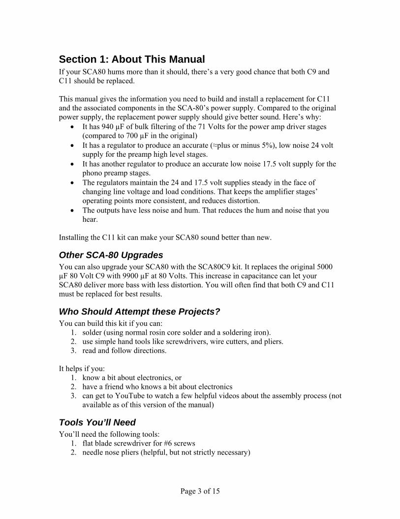
Section 1: About This Manual If your SCA80 hums more than it should, there’s a very good chance that both C9 and C11 should be replaced. This manual gives the information you need to build and install a replacement for C11 and the associated components in the SCA-80’s power supply. Compared to the original power supply, the replacement power supply should give better sound. Here’s why:
It has 940 µF of bulk filtering of the 71 Volts for the power amp driver stages (compared to 700 µF in the original)
It has a regulator to produce an accurate (≈plus or minus 5%), low noise 24 volt supply for the preamp high level stages.
It has another regulator to produce an accurate low noise 17.5 volt supply for the phono preamp stages.
The regulators maintain the 24 and 17.5 volt supplies steady in the face of changing line voltage and load conditions. That keeps the amplifier stages’ operating points more consistent, and reduces distortion.
The outputs have less noise and hum. That reduces the hum and noise that you hear.
Installing the C11 kit can make your SCA80 sound better than new.
Other SCA-80 Upgrades You can also upgrade your SCA80 with the SCA80C9 kit. It replaces the original 5000 µF 80 Volt C9 with 9900 µF at 80 Volts. This increase in capacitance can let your SCA80 deliver more bass with less distortion. You will often find that both C9 and C11 must be replaced for best results.
Who Should Attempt these Projects? You can build this kit if you can:
1. solder (using normal rosin core solder and a soldering iron). 2. use simple hand tools like screwdrivers, wire cutters, and pliers. 3. read and follow directions.
It helps if you:
1. know a bit about electronics, or 2. have a friend who knows a bit about electronics 3. can get to YouTube to watch a few helpful videos about the assembly process (not
available as of this version of the manual)
Tools You’ll Need You’ll need the following tools:
1. flat blade screwdriver for #6 screws 2. needle nose pliers (helpful, but not strictly necessary)
Page 4 of 15
3. pencil type soldering iron of 25 to 50 Watts (no huge honking soldering guns or blowtorches)
4. wire cutters and strippers 5. Magnifying glass, if you’re over 42!
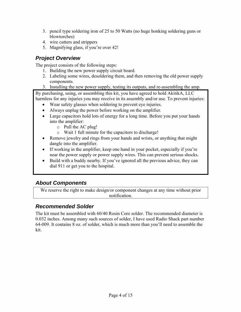
Project Overview The project consists of the following steps:
1. Building the new power supply circuit board. 2. Labeling some wires, desoldering them, and then removing the old power supply
components. 3. Installing the new power supply, testing its outputs, and re-assembling the amp.
By purchasing, using, or assembling this kit, you have agreed to hold AkitikA, LLC harmless for any injuries you may receive in its assembly and/or use. To prevent injuries:
Wear safety glasses when soldering to prevent eye injuries. Always unplug the power before working on the amplifier. Large capacitors hold lots of energy for a long time. Before you put your hands
into the amplifier: o Pull the AC plug! o Wait 1 full minute for the capacitors to discharge!
Remove jewelry and rings from your hands and wrists, or anything that might dangle into the amplifier.
If working in the amplifier, keep one hand in your pocket, especially if you’re near the power supply or power supply wires. This can prevent serious shocks.
Build with a buddy nearby. If you’ve ignored all the previous advice, they can dial 911 or get you to the hospital.
About Components We reserve the right to make design/or component changes at any time without prior
notification.
Recommended Solder The kit must be assembled with 60/40 Rosin Core solder. The recommended diameter is 0.032 inches. Among many such sources of solder, I have used Radio Shack part number 64-009. It contains 8 oz. of solder, which is much more than you’ll need to assemble the kit.
Page 5 of 15
Section 2: Building the Power Supply PC Board
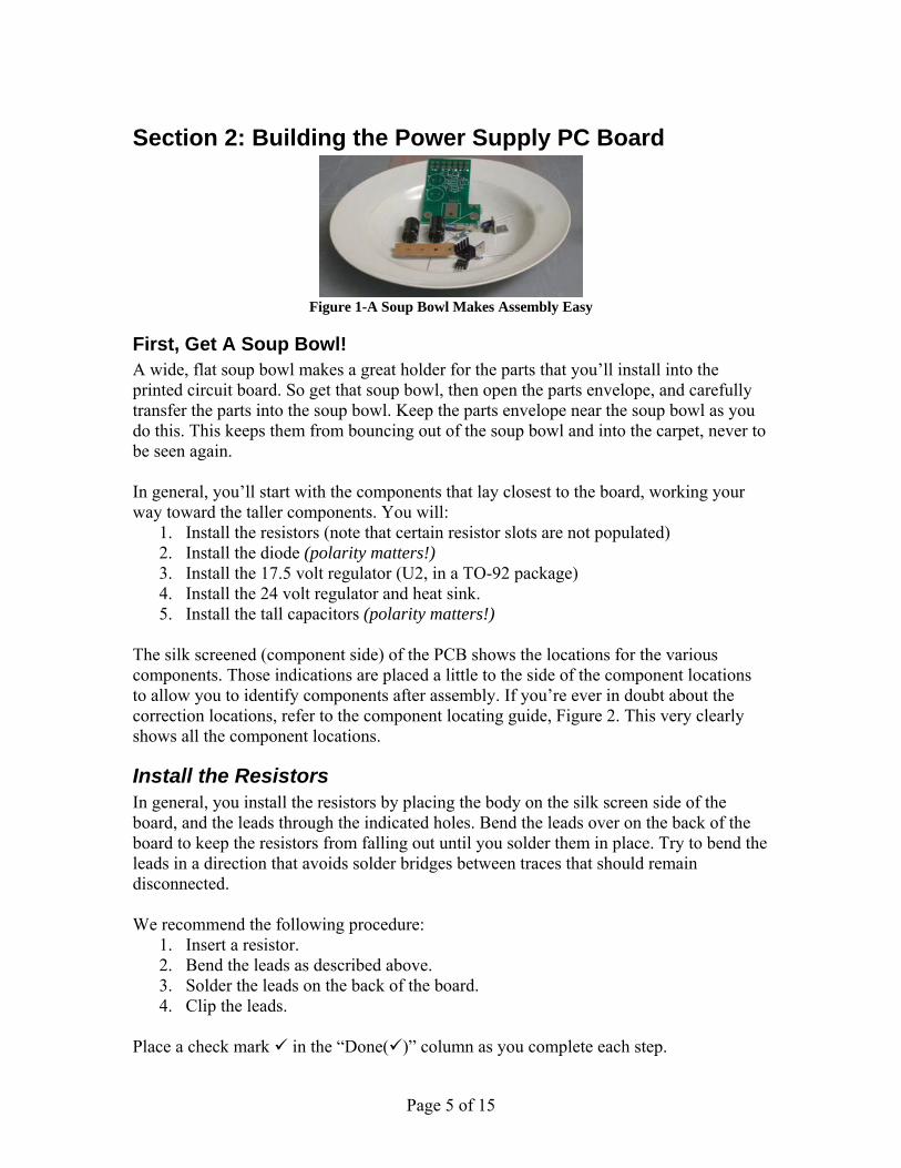
Figure 1-A Soup Bowl Makes Assembly Easy
First, Get A Soup Bowl! A wide, flat soup bowl makes a great holder for the parts that you’ll install into the printed circuit board. So get that soup bowl, then open the parts envelope, and carefully transfer the parts into the soup bowl. Keep the parts envelope near the soup bowl as you do this. This keeps them from bouncing out of the soup bowl and into the carpet, never to be seen again. In general, you’ll start with the components that lay closest to the board, working your way toward the taller components. You will:
1. Install the resistors (note that certain resistor slots are not populated) 2. Install the diode (polarity matters!) 3. Install the 17.5 volt regulator (U2, in a TO-92 package) 4. Install the 24 volt regulator and heat sink. 5. Install the tall capacitors (polarity matters!)
The silk screened (component side) of the PCB shows the locations for the various components. Those indications are placed a little to the side of the component locations to allow you to identify components after assembly. If you’re ever in doubt about the correction locations, refer to the component locating guide, Figure 2. This very clearly shows all the component locations.
Install the Resistors In general, you install the resistors by placing the body on the silk screen side of the board, and the leads through the indicated holes. Bend the leads over on the back of the board to keep the resistors from falling out until you solder them in place. Try to bend the leads in a direction that avoids solder bridges between traces that should remain disconnected. We recommend the following procedure:
1. Insert a resistor. 2. Bend the leads as described above. 3. Solder the leads on the back of the board. 4. Clip the leads.
Place a check mark in the “Done()” column as you complete each step.

Page 6 of 15
Figure 2-Guide to component installation
Designation Value Color Code Done() R1 649 Blue, Yellow, White, Black, Brown R2 - Leave this slot empty R3 649 Blue, Yellow, White, Black, Brown R4 60K4 Blue, Black, Yellow, Red, Brown R5 11K Brown, Brown, Black, Red, Brown R6 - Leave this slot empty R7 10K Brown, Black, Black, Red, Brown
Page 7 of 15
Resistor Notes All the resistors are ¼ W, 1%, Metal Film K stands for 1000. Thus, 60K4 is a short-hand that means 60,400 Ohms. Some
people like to convert the K notation to a number by: 1. Replace the K by a decimal point. 2. Multiply the resulting number by 1000.
Resistor orientation does not matter. Feel free to use a DMM (digital multi-meter) to confirm the resistor values before
installation.
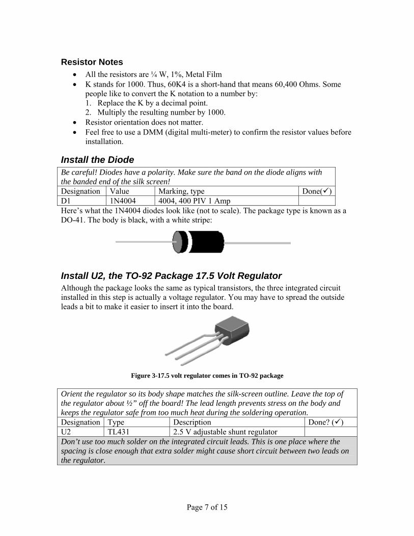
Install the Diode Be careful! Diodes have a polarity. Make sure the band on the diode aligns with the banded end of the silk screen! Designation Value Marking, type Done() D1 1N4004 4004, 400 PIV 1 Amp Here’s what the 1N4004 diodes look like (not to scale). The package type is known as a DO-41. The body is black, with a white stripe:
Install U2, the TO-92 Package 17.5 Volt Regulator Although the package looks the same as typical transistors, the three integrated circuit installed in this step is actually a voltage regulator. You may have to spread the outside leads a bit to make it easier to insert it into the board.
Figure 3-17.5 volt regulator comes in TO-92 package
Orient the regulator so its body shape matches the silk-screen outline. Leave the top of the regulator about ½” off the board! The lead length prevents stress on the body and keeps the regulator safe from too much heat during the soldering operation. Designation Type Description Done? () U2 TL431 2.5 V adjustable shunt regulator Don’t use too much solder on the integrated circuit leads. This is one place where the spacing is close enough that extra solder might cause short circuit between two leads on the regulator.
Page 8 of 15
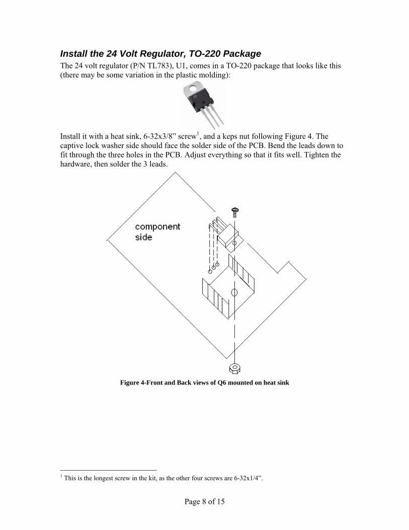
Install the 24 Volt Regulator, TO-220 Package The 24 volt regulator (P/N TL783), U1, comes in a TO-220 package that looks like this (there may be some variation in the plastic molding):
Install it with a heat sink, 6-32x3/8” screw1, and a keps nut following Figure 4. The captive lock washer side should face the solder side of the PCB. Bend the leads down to fit through the three holes in the PCB. Adjust everything so that it fits well. Tighten the hardware, then solder the 3 leads.
Figure 4-Front and Back views of Q6 mounted on heat sink
1 This is the longest screw in the kit, as the other four screws are 6-32x1/4”.

Page 9 of 15
Install the Capacitors Install the polarized electrolytic capacitors. Note that + sign on the silk-screen shows where the positive side of the capacitor should go. However, the markings on the caps prominently show the negative side. Make sure that the non-negative side of the cap connects to the hole indicated by the positive sign on the silk screen. Designation Value Marking Done? () C1 22 µF, 63 V 22 µF, 63 V, and minus sign for polarity C2 22 µF, 63 V 22 µF, 63 V, and minus sign for polarity C3 470 µF, 100
V 470 µF, 100 V, and minus sign for polarity
C4 470 µF, 100 V
470 µF, 100 V, and minus sign for polarity
Solder GJ1 in Place Insert a piece of 20 AWG wire from the component side of the board into the two holes adjacent to GJ1 on the silk screen. Solder both ends of the wire on the solder side of the PCB.
Remove the Old Power Supply 1. Disconnect the SCA-80 from your music system. 2. Unplug the power cord and allow the amp to sit for one minute before moving on.
Caution: Be sure that the power is unplugged! 120/240 VAC can be lethal! 3. Remove the 5 screws that hold the cover in place, 2 on the left side, 2 on the right
side, and one in the back. 4. Lift the cover straight up and set it aside in a safe place.
Figure 5-Remove these wires from C11

Page 10 of 15
Get masking tape and a pen so you can mark the wires that connect to C11 before removing them. Mark them as indicated in this table.
Mark Label with
Number of wires
Where wires connected Done()
3 terminal of C11, where the 4700 Ohms and 10 K Ohm resistors come together.
1 terminal of C11, the other side of the 10 K resistor 1 terminal of C11, the other side of the 4700 Ohm
resistor
4G 4 Can of C11, terminal where 4 wires come together 2G 2 Can of C11, terminal where 2 wires come together
5. Remove the two screws, nuts, and lock washers that hold C11’s clamp into the chassis. Remove C11 along with the two resistors.
6. Save the capacitor clamp, but neither the capacitor the resistors will be re-used.
Install the New Power Supply 7. Attach the mounting brackets to the assembled power supply PCB using two 6-
32x1/4” sems screws (sems screws have the captive lock washer). Make sure that they’re both straight and tight.
Figure 6-Mounting the power supply to the SCA80
8. Use the old mounting holes from C11 to fasten the brackets to the chassis. See Figure 6.

Page 11 of 15
Figure 7-Showing location of C11
Page 12 of 15
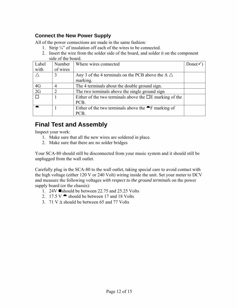
Connect the New Power Supply All of the power connections are made in the same fashion:
1. Strip ¼” of insulation off each of the wires to be connected. 2. Insert the wire from the solder side of the board, and solder it on the component
side of the board. Label with
Number of wires
Where wires connected Done()
3 Any 3 of the 4 terminals on the PCB above the A marking.
4G 4 The 4 terminals about the double ground sign. 2G 2 The two terminals above the single ground sign 1 Either of the two terminals above the E marking of the
PCB.
1 Either of the two terminals above the F marking of PCB.
Final Test and Assembly Inspect your work:
1. Make sure that all the new wires are soldered in place. 2. Make sure that there are no solder bridges
Your SCA-80 should still be disconnected from your music system and it should still be unplugged from the wall outlet. Carefully plug in the SCA-80 to the wall outlet, taking special care to avoid contact with the high voltage (either 120 V or 240 Volt) wiring inside the unit. Set your meter to DCV and measure the following voltages with respect to the ground terminals on the power supply board (or the chassis):
1. 24V should be between 22.75 and 25.25 Volts 2. 17.5 V should be between 17 and 18 Volts 3. 71 V should be between 65 and 77 Volts

Page 13 of 15
Figure 8-New Power Supply Installed in SCA80(Q)
If the voltages check out in the previous step, then: 1. Remove the AC plug from the wall outlet. 2. Wait one minute to allow the caps to discharge. 3. Put the top back on, and re-install the five screws that hold it in place. 4. Reinstall the SCA-80 to your music system.
Figure 9-Close up of Assembled Circuit Board
Page 14 of 15
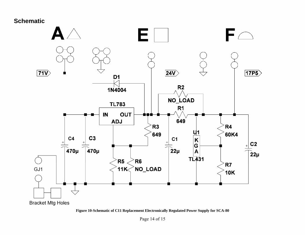
Schematic
Figure 10-Schematic of C11 Replacement Electronically Regulated Power Supply for SCA-80

Page 15 of 15
Resistor Color Code
Figure 11-demonstrating the resistor color code
Here’s an extreme close-up of a ¼ W metal film 20K (20,000) Ohm resistor, designated by the standard resistor color code. The colors map to numbers: Color Number Black 0 Brown 1 Red 2 Orange 3 Yellow 4 Green 5 Blue 6 Violet 7 Gray 8 White 9 The color band positions have the following meaning: Position Meaning 1 Left-most Digit (e.g. most significant) 2 Next digit to the right 3 Next digit to the right. 4 Number of zeros that follow the three digits, unless:
Band 4 is gold => multiply by 0.1 Band 4 is silver=> multiply by 0.01
**Yellow Tolerance: Brown =>1% Red => 2% Gold=> 5% Silver=>10% No band=>20%