Shear Strength Experiments and Design of Cold-formed Steel ...
42
2 Shear Strength Experiments and Design of Cold-formed Steel Channels with Web Holes Song Hong Pham 1 , Cao Hung Pham 2 , Colin A. Rogers 3 and Gregory J Hancock 4 Abstract In the latest North American Specification for the design of cold-formed steel (CFS) structural members and the Australian/New Zealand Standard for cold-formed steel structures, an empirical approach is specified to design beams with web holes in shear. Recently, an alternative based on the Direct Strength Method (DSM) of design for shear for perforated beams with the aspect ratio (shear- span/web-depth) of 1.0 has been proposed. This paper presents a comprehensive review of the proposal and an experimental validation using results from a test series on channels with a shear span aspect ratio of 2.0 and with various square and circular web opening sizes conducted at the University of Sydney, and other experimental data collected from the literature. It is proven that the earlier proposal reliably predicts the shear strength of CFS perforated members with central square and circular web holes and with an aspect ratio up to 2.0. An approximate equation to determine shear buckling coefficients is derived to allow shear buckling forces, an input of the DSM design equation, to be computed directly on the basis of geometrical dimensions of perforated members. Finite element models of the tests are also developed and validated to study the variation of the shear strengths with respect to the hole sizes where considerable shear strengths of members with substantially large web holes extending up to the full depths of the webs are observed. Further, the experimental shear strengths are used to calibrate the DSM-based proposal. It is confirmed that the resistance factors for shear design being used in the current North American Specification and Australian/New Zealand Standard are applicable. 1 Doctoral Candidate, School of Civil Engineering, The University of Sydney, NSW 2006, Australia. E-mail: [email protected]. 2 Senior Lecturer in Structural Engineering, School of Civil Engineering, The University of Sydney, NSW 2006, Australia. E-mail: [email protected]. 3 Associate Professor, Department of Civil Engineering and Applied Mechanics, McGill University, Canada. E-mail: [email protected] 4 Emeritus Professor and Professorial Research Fellow, School of Civil Engineering, The University of Sydney, NSW 2006, Australia. E-mail: [email protected]
Transcript of Shear Strength Experiments and Design of Cold-formed Steel ...
2
Shear Strength Experiments and Design of Cold-formed Steel Channels with Web Holes
Song Hong Pham1, Cao Hung Pham2, Colin A. Rogers3 and Gregory J Hancock4
Abstract
In the latest North American Specification for the design of cold-formed steel (CFS) structural
members and the Australian/New Zealand Standard for cold-formed steel structures, an empirical
approach is specified to design beams with web holes in shear. Recently, an alternative based on the
Direct Strength Method (DSM) of design for shear for perforated beams with the aspect ratio (shear-
span/web-depth) of 1.0 has been proposed. This paper presents a comprehensive review of the
proposal and an experimental validation using results from a test series on channels with a shear span
aspect ratio of 2.0 and with various square and circular web opening sizes conducted at the University
of Sydney, and other experimental data collected from the literature. It is proven that the earlier
proposal reliably predicts the shear strength of CFS perforated members with central square and
circular web holes and with an aspect ratio up to 2.0. An approximate equation to determine shear
buckling coefficients is derived to allow shear buckling forces, an input of the DSM design equation,
to be computed directly on the basis of geometrical dimensions of perforated members. Finite element
models of the tests are also developed and validated to study the variation of the shear strengths with
respect to the hole sizes where considerable shear strengths of members with substantially large web
holes extending up to the full depths of the webs are observed. Further, the experimental shear
strengths are used to calibrate the DSM-based proposal. It is confirmed that the resistance factors for
shear design being used in the current North American Specification and Australian/New Zealand
Standard are applicable.
1 Doctoral Candidate, School of Civil Engineering, The University of Sydney, NSW 2006, Australia. E-mail: [email protected]. 2 Senior Lecturer in Structural Engineering, School of Civil Engineering, The University of Sydney, NSW 2006, Australia. E-mail: [email protected]. 3 Associate Professor, Department of Civil Engineering and Applied Mechanics, McGill University, Canada. E-mail: [email protected] 4 Emeritus Professor and Professorial Research Fellow, School of Civil Engineering, The University of Sydney, NSW 2006, Australia. E-mail: [email protected]
jinnes
Typewritten Text
This material may be downloaded for personal use only. Any other use requires prior permission of the American Society of Civil Engineers. This material may be found at Pham SH, Pham CH, Rogers CA, Hancock GJ (2020) "Shear strength experiments and design of cold-formed steel channels with web holes", ASCE Journal of Structural Engineering 146(1): 04019173. https://doi.org/10.1061/(ASCE)ST.1943-541X.0002464
jinnes
Typewritten Text
jinnes
Typewritten Text
jinnes
Typewritten Text
jinnes
Typewritten Text
jinnes
Typewritten Text
3
Introduction
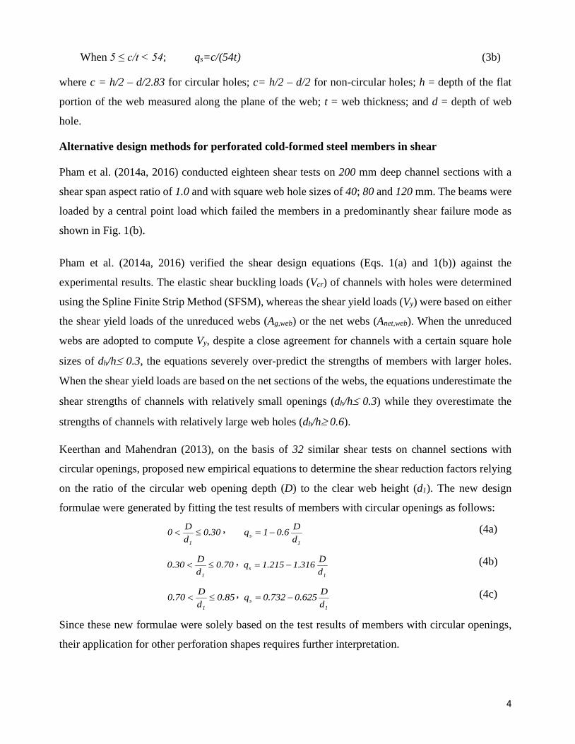
For unperforated members subjected to shear force, the design rules in the AISI S100-16 Section
G2.2 (AISI 2016) and the Australian/New Zealand Standard for cold-formed steel structures AS/NZS
4600:2018 (Standards Australia 2018) allow direct computation of the shear strength (Vn) as given
by Eqs. (1) and (2). These equations were based on those for the Direct Strength Method in Appendix
1 of the AISI S100-12 (AISI 2012) but are now applicable to all methodologies.
For 0.776λv ≤
yn VV = (1a)
For 0.776λv >
y
4.0
y
cr
4.0
y
crn V
VV
VV0.151V
−= (1b)
where
crVyV
vλ =
crV is elastic shear buckling force of CFS sections,
( )
22
w2
vcr
thν112
EAπkV
−
= (2)
kv is shear buckling coefficient of the whole section including flanges and lips assuming an
average buckling stress in the web which is given in (Pham and Hancock 2009, 2012c) for
plain lipped channels based on the Spline Finite Strip Method (SFSM), h is the depth of the
flat portion of the web, t is the thickness of the web, E is Young's modulus of steel, and ν is
Poisson's ratio of steel.
Vy is the yield shear load of the flat web, Vy = 0.6fyAw where Aw is the cross-sectional area of
the flat web element, fy is the design yield stress
However, for perforated members in shear, both the AISI S100-16 and the AS/NZS 4600:2018 still
adopt an empirical approach based on the experimental research by Shan et al. (1994), Schuster et al.
(1995), and Eiler et al. (1997). This method allows shear strengths of CFS members with web holes
to be computed as a product of a strength reduction factor (qs) and the shear strength of members
without web holes as follows:
When c/t ≥ 54; qs=1 (3a)
4
When 5 ≤ c/t < 54; qs=c/(54t) (3b)
where c = h/2 – d/2.83 for circular holes; c= h/2 – d/2 for non-circular holes; h = depth of the flat
portion of the web measured along the plane of the web; t = web thickness; and d = depth of web
hole.
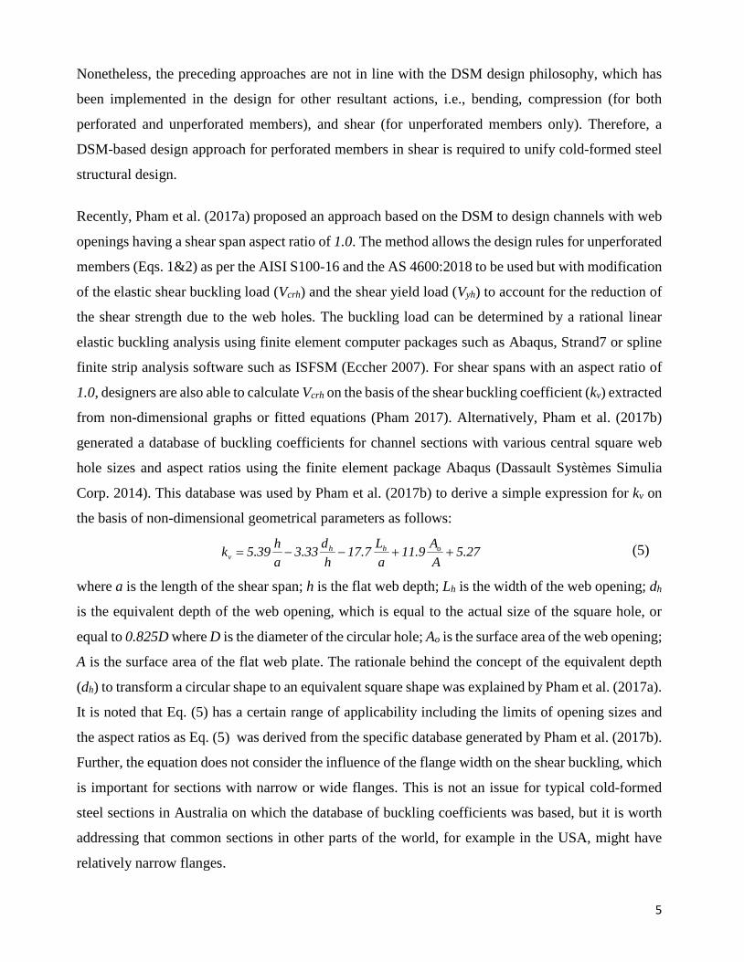
Alternative design methods for perforated cold-formed steel members in shear Pham et al. (2014a, 2016) conducted eighteen shear tests on 200 mm deep channel sections with a
shear span aspect ratio of 1.0 and with square web hole sizes of 40; 80 and 120 mm. The beams were
loaded by a central point load which failed the members in a predominantly shear failure mode as
shown in Fig. 1(b).
Pham et al. (2014a, 2016) verified the shear design equations (Eqs. 1(a) and 1(b)) against the
experimental results. The elastic shear buckling loads (Vcr) of channels with holes were determined
using the Spline Finite Strip Method (SFSM), whereas the shear yield loads (Vy) were based on either
the shear yield loads of the unreduced webs (Ag,web) or the net webs (Anet,web). When the unreduced
webs are adopted to compute Vy, despite a close agreement for channels with a certain square hole
sizes of dh/h≤ 0.3, the equations severely over-predict the strengths of members with larger holes.
When the shear yield loads are based on the net sections of the webs, the equations underestimate the
shear strengths of channels with relatively small openings (dh/h≤ 0.3) while they overestimate the
strengths of channels with relatively large web holes (dh/h≥ 0.6).
Keerthan and Mahendran (2013), on the basis of 32 similar shear tests on channel sections with
circular openings, proposed new empirical equations to determine the shear reduction factors relying
on the ratio of the circular web opening depth (D) to the clear web height (d1). The new design
formulae were generated by fitting the test results of members with circular openings as follows:
30.0dD0
1
≤< , 1
s dD6.01q −= (4a)
70.0dD30.0
1
≤< , 1
s dD316.1215.1q −= (4b)
85.0dD70.0
1
≤< , 1
s dD625.0732.0q −= (4c)
Since these new formulae were solely based on the test results of members with circular openings,
their application for other perforation shapes requires further interpretation.
5
Nonetheless, the preceding approaches are not in line with the DSM design philosophy, which has
been implemented in the design for other resultant actions, i.e., bending, compression (for both
perforated and unperforated members), and shear (for unperforated members only). Therefore, a
DSM-based design approach for perforated members in shear is required to unify cold-formed steel
structural design.
Recently, Pham et al. (2017a) proposed an approach based on the DSM to design channels with web
openings having a shear span aspect ratio of 1.0. The method allows the design rules for unperforated
members (Eqs. 1&2) as per the AISI S100-16 and the AS 4600:2018 to be used but with modification
of the elastic shear buckling load (Vcrh) and the shear yield load (Vyh) to account for the reduction of
the shear strength due to the web holes. The buckling load can be determined by a rational linear
elastic buckling analysis using finite element computer packages such as Abaqus, Strand7 or spline
finite strip analysis software such as ISFSM (Eccher 2007). For shear spans with an aspect ratio of
1.0, designers are also able to calculate Vcrh on the basis of the shear buckling coefficient (kv) extracted
from non-dimensional graphs or fitted equations (Pham 2017). Alternatively, Pham et al. (2017b)
generated a database of buckling coefficients for channel sections with various central square web
hole sizes and aspect ratios using the finite element package Abaqus (Dassault Systèmes Simulia
Corp. 2014). This database was used by Pham et al. (2017b) to derive a simple expression for kv on
the basis of non-dimensional geometrical parameters as follows:
27.5AA9.11
aL7.17
hd33.3
ah39.5k ohh
v ++−−= (5)
where a is the length of the shear span; h is the flat web depth; Lh is the width of the web opening; dh
is the equivalent depth of the web opening, which is equal to the actual size of the square hole, or
equal to 0.825D where D is the diameter of the circular hole; Ao is the surface area of the web opening;
A is the surface area of the flat web plate. The rationale behind the concept of the equivalent depth
(dh) to transform a circular shape to an equivalent square shape was explained by Pham et al. (2017a).
It is noted that Eq. (5) has a certain range of applicability including the limits of opening sizes and
the aspect ratios as Eq. (5) was derived from the specific database generated by Pham et al. (2017b).
Further, the equation does not consider the influence of the flange width on the shear buckling, which
is important for sections with narrow or wide flanges. This is not an issue for typical cold-formed
steel sections in Australia on which the database of buckling coefficients was based, but it is worth
addressing that common sections in other parts of the world, for example in the USA, might have
relatively narrow flanges.
6
In this paper, for elastic buckling analysis, the database is extended with more data points and to
cover the influence of the flange width. In total, seven hundred and sixty-eight finite element models
with central square web holes, as described in Pham et al. (2017b), were constructed and analysed,
aided by a customised Matlab code to generate the Abaqus input files, and a Python script to run the
eigenbuckling analyses using the Abaqus processor and to extract the buckling loads. The models
included 200 mm deep channel section beams with shear-span-to-web-depth aspect ratios of 1.0, 2.0
and 3.0; square hole sizes with the dh/h ratio ranging from 0.1 to 0.8; thicknesses of 1.2, 1.5, 2.4 and
3.0 mm and flange widths of 50, 60, 75 and 85 mm, i.e. the bf/h ratio ranging from 0.27 to 0.45. The
buckling coefficients were subsequently back computed, and the database was used to generate the
following equation to approximate the values of kv:
86.4h
b57.0
AA88.13
aL58.19
hd63.3
ah15.6k fohh
v +++−−= (6)
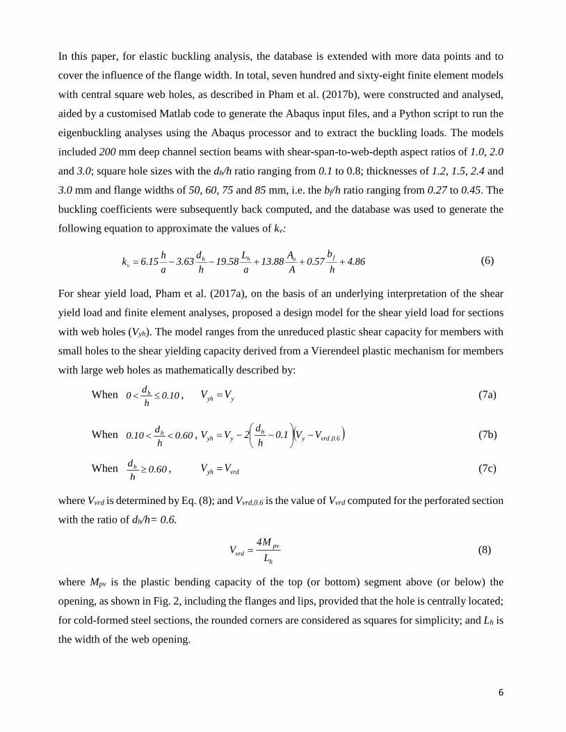
For shear yield load, Pham et al. (2017a), on the basis of an underlying interpretation of the shear
yield load and finite element analyses, proposed a design model for the shear yield load for sections
with web holes (Vyh). The model ranges from the unreduced plastic shear capacity for members with
small holes to the shear yielding capacity derived from a Vierendeel plastic mechanism for members
with large web holes as mathematically described by:
When 10.0hd0 h ≤< , yyh VV = (7a)
When 60.0hd10.0 h << , ( )6.0,vrdy
hyyh VV1.0
hd2VV −
−−= (7b)
When 60.0hdh ≥ , vrdyh VV = (7c)
where Vvrd is determined by Eq. (8); and Vvrd,0.6 is the value of Vvrd computed for the perforated section
with the ratio of dh/h= 0.6.
h
pvvrd L
M4V = (8)
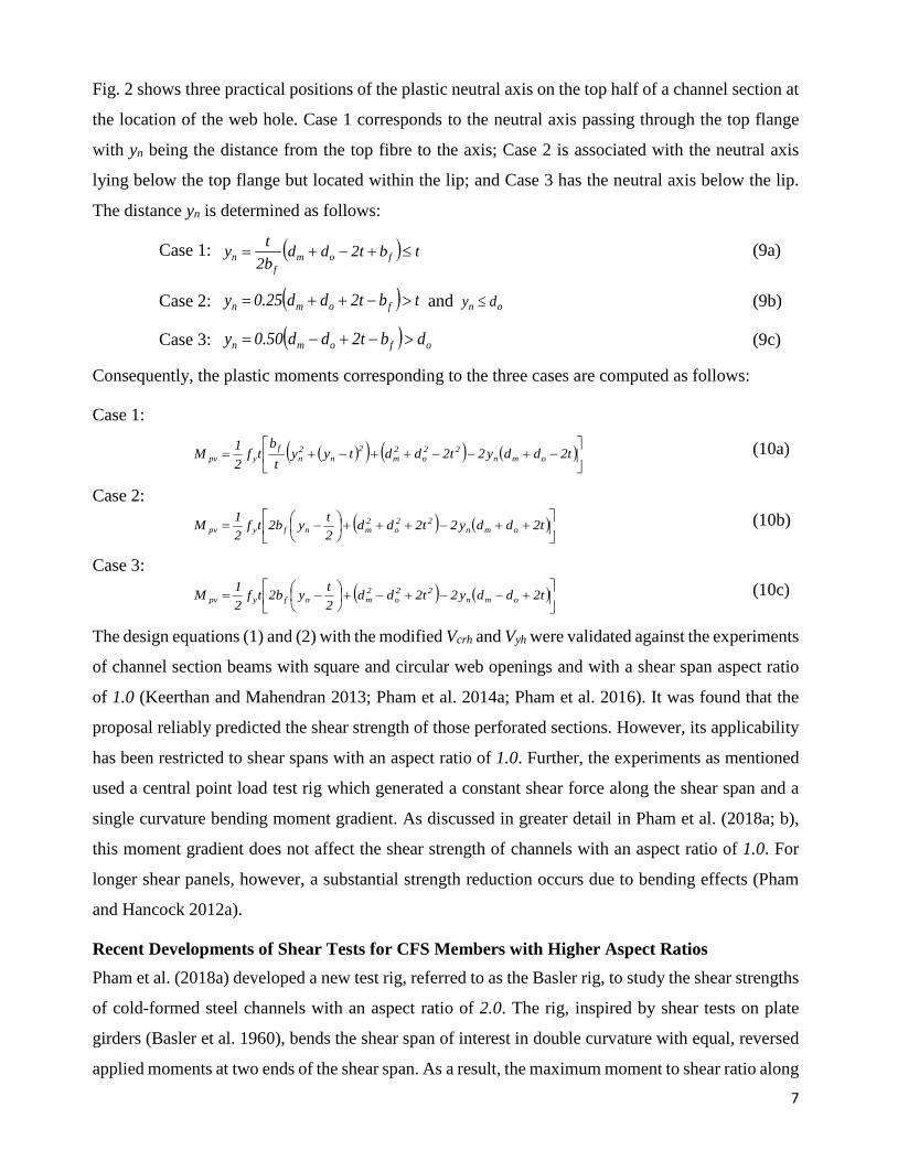
where Mpv is the plastic bending capacity of the top (or bottom) segment above (or below) the
opening, as shown in Fig. 2, including the flanges and lips, provided that the hole is centrally located;
for cold-formed steel sections, the rounded corners are considered as squares for simplicity; and Lh is
the width of the web opening.
7
Fig. 2 shows three practical positions of the plastic neutral axis on the top half of a channel section at
the location of the web hole. Case 1 corresponds to the neutral axis passing through the top flange
with yn being the distance from the top fibre to the axis; Case 2 is associated with the neutral axis
lying below the top flange but located within the lip; and Case 3 has the neutral axis below the lip.
The distance yn is determined as follows:
Case 1: ( ) tbt2ddb2ty fom
fn ≤+−+= (9a)
Case 2: ( ) tbt2dd25.0y fomn >−++= and on dy ≤ (9b)
Case 3: ( ) ofomn dbt2dd50.0y >−+−= (9c)
Consequently, the plastic moments corresponding to the three cases are computed as follows:
Case 1:
( )( ) ( ) ( )
−+−−++−+= t2ddy2t2ddtyy
tb
tf21M omn
22o
2m
2n
2n
fypv
(10a)
Case 2: ( ) ( )
++−+++
−= t2ddy2t2dd
2tyb2tf
21M omn
22o
2mnfypv
(10b)
Case 3: ( ) ( )
+−−+−+
−= t2ddy2t2dd
2tyb2tf
21M omn
22o
2mnfypv
(10c)
The design equations (1) and (2) with the modified Vcrh and Vyh were validated against the experiments
of channel section beams with square and circular web openings and with a shear span aspect ratio
of 1.0 (Keerthan and Mahendran 2013; Pham et al. 2014a; Pham et al. 2016). It was found that the
proposal reliably predicted the shear strength of those perforated sections. However, its applicability
has been restricted to shear spans with an aspect ratio of 1.0. Further, the experiments as mentioned
used a central point load test rig which generated a constant shear force along the shear span and a
single curvature bending moment gradient. As discussed in greater detail in Pham et al. (2018a; b),
this moment gradient does not affect the shear strength of channels with an aspect ratio of 1.0. For
longer shear panels, however, a substantial strength reduction occurs due to bending effects (Pham
and Hancock 2012a).
Recent Developments of Shear Tests for CFS Members with Higher Aspect Ratios Pham et al. (2018a) developed a new test rig, referred to as the Basler rig, to study the shear strengths
of cold-formed steel channels with an aspect ratio of 2.0. The rig, inspired by shear tests on plate
girders (Basler et al. 1960), bends the shear span of interest in double curvature with equal, reversed
applied moments at two ends of the shear span. As a result, the maximum moment to shear ratio along
8
the shear span is reduced to half of the ratio produced by the conventional central point load shear
tests. A test series on channel sections without web holes was carried out to verify the new test rig,
which saw a substantial shear strength enhancement, up to 40%, due to the low moment-to-shear
ratio. This philosophy was adopted for further development of a simpler and more economical test
rig, referred to as the dual actuator test rig (Pham et al. 2018b). The dual actuator rig is capable of
minimizing the bending-to-shear ratio, as does the Basler rig, but with much simpler specimen
preparation and reduced time and cost.
This paper introduces a test series on high strength cold-formed steel channels with an aspect ratio of
2.0 and with various central square and circular web holes using the newly designed dual actuator
test rig. As the details and the validation of the test rig can be found in the above-mentioned
references, only a brief introduction of the testing protocol is presented herein. Finite element models
are also developed and calibrated against the experimental results prior to being used for a parametric
study of channels with a wide range of hole sizes. The experimental results are used to validate and
extend the proposal of shear design for structures with web holes (Pham et al. 2017a) to shear spans
with aspect ratios up to 2.0. Available experimental results (Keerthan and Mahendran 2013; Pham et
al. 2014a, 2016) are combined and used to calibrate the DSM-based proposal for the design of cold-
formed steel channels with web holes in shear.
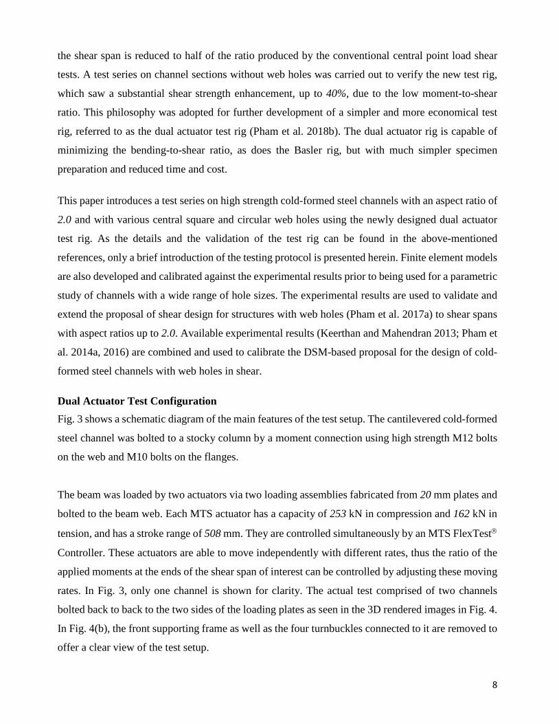
Dual Actuator Test Configuration Fig. 3 shows a schematic diagram of the main features of the test setup. The cantilevered cold-formed
steel channel was bolted to a stocky column by a moment connection using high strength M12 bolts
on the web and M10 bolts on the flanges.
The beam was loaded by two actuators via two loading assemblies fabricated from 20 mm plates and
bolted to the beam web. Each MTS actuator has a capacity of 253 kN in compression and 162 kN in
tension, and has a stroke range of 508 mm. They are controlled simultaneously by an MTS FlexTest
Controller. These actuators are able to move independently with different rates, thus the ratio of the
applied moments at the ends of the shear span of interest can be controlled by adjusting these moving
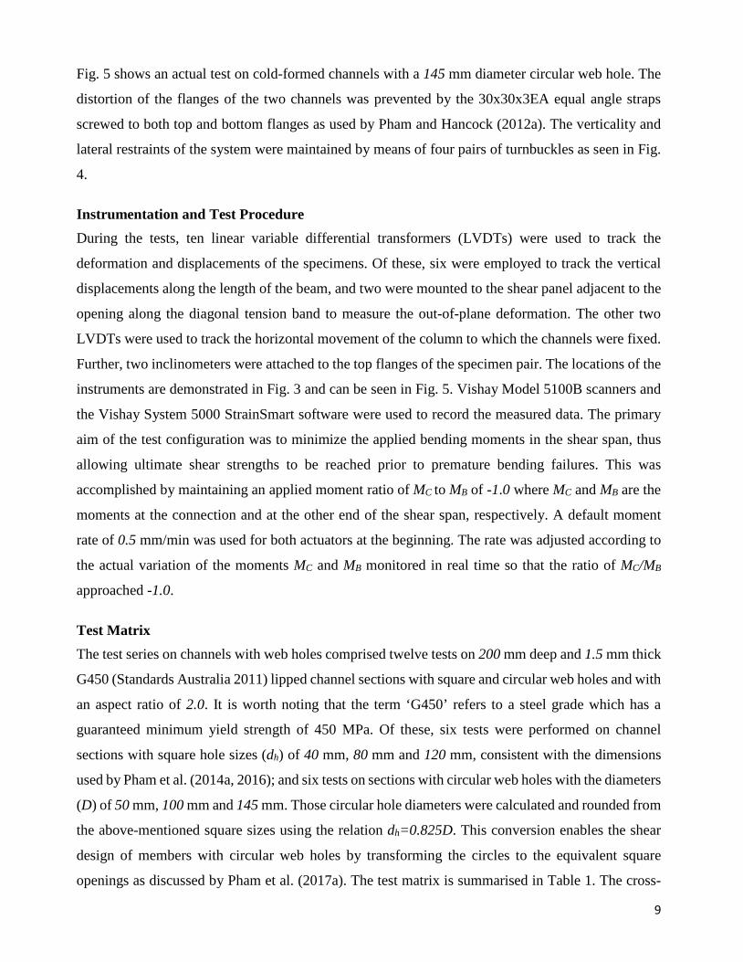
rates. In Fig. 3, only one channel is shown for clarity. The actual test comprised of two channels
bolted back to back to the two sides of the loading plates as seen in the 3D rendered images in Fig. 4.
In Fig. 4(b), the front supporting frame as well as the four turnbuckles connected to it are removed to
offer a clear view of the test setup.
9
Fig. 5 shows an actual test on cold-formed channels with a 145 mm diameter circular web hole. The
distortion of the flanges of the two channels was prevented by the 30x30x3EA equal angle straps
screwed to both top and bottom flanges as used by Pham and Hancock (2012a). The verticality and
lateral restraints of the system were maintained by means of four pairs of turnbuckles as seen in Fig.
4.
Instrumentation and Test Procedure During the tests, ten linear variable differential transformers (LVDTs) were used to track the
deformation and displacements of the specimens. Of these, six were employed to track the vertical
displacements along the length of the beam, and two were mounted to the shear panel adjacent to the
opening along the diagonal tension band to measure the out-of-plane deformation. The other two
LVDTs were used to track the horizontal movement of the column to which the channels were fixed.
Further, two inclinometers were attached to the top flanges of the specimen pair. The locations of the
instruments are demonstrated in Fig. 3 and can be seen in Fig. 5. Vishay Model 5100B scanners and
the Vishay System 5000 StrainSmart software were used to record the measured data. The primary
aim of the test configuration was to minimize the applied bending moments in the shear span, thus
allowing ultimate shear strengths to be reached prior to premature bending failures. This was
accomplished by maintaining an applied moment ratio of MC to MB of -1.0 where MC and MB are the
moments at the connection and at the other end of the shear span, respectively. A default moment
rate of 0.5 mm/min was used for both actuators at the beginning. The rate was adjusted according to
the actual variation of the moments MC and MB monitored in real time so that the ratio of MC/MB
approached -1.0.
Test Matrix The test series on channels with web holes comprised twelve tests on 200 mm deep and 1.5 mm thick
G450 (Standards Australia 2011) lipped channel sections with square and circular web holes and with
an aspect ratio of 2.0. It is worth noting that the term ‘G450’ refers to a steel grade which has a
guaranteed minimum yield strength of 450 MPa. Of these, six tests were performed on channel
sections with square hole sizes (dh) of 40 mm, 80 mm and 120 mm, consistent with the dimensions
used by Pham et al. (2014a, 2016); and six tests on sections with circular web holes with the diameters
(D) of 50 mm, 100 mm and 145 mm. Those circular hole diameters were calculated and rounded from
the above-mentioned square sizes using the relation dh=0.825D. This conversion enables the shear
design of members with circular web holes by transforming the circles to the equivalent square
openings as discussed by Pham et al. (2017a). The test matrix is summarised in Table 1. The cross-
10
sectional dimensions of individual channels are given in Tables 2 and 3 with the dimension notations
illustrated in Fig. 6. A typical test designation of “C20015- S40” is defined as follows
• “C200” indicates a channel section with the web depth of 200 mm,
• “15” indicates the thickness times 10 in mm,
• “S40” indicates a square hole size of 40 mm. Alternatively, “C50” indicates a circular hole with
the diameter (D) of 50 mm.
The material yield stress (fy) was measured by tensile coupon tests according to the Australian
Standard for metallic materials- Tensile testing at ambient temperature AS 1391-2007 (Standards
Australia 2005) and the average value is provided in Table 1.
Experimental Results
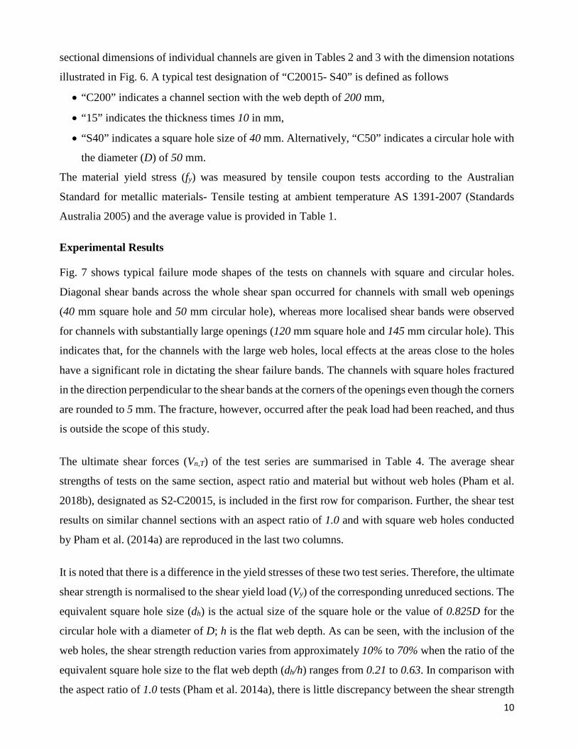
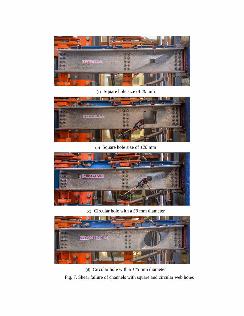
Fig. 7 shows typical failure mode shapes of the tests on channels with square and circular holes.
Diagonal shear bands across the whole shear span occurred for channels with small web openings
(40 mm square hole and 50 mm circular hole), whereas more localised shear bands were observed
for channels with substantially large openings (120 mm square hole and 145 mm circular hole). This
indicates that, for the channels with the large web holes, local effects at the areas close to the holes
have a significant role in dictating the shear failure bands. The channels with square holes fractured
in the direction perpendicular to the shear bands at the corners of the openings even though the corners
are rounded to 5 mm. The fracture, however, occurred after the peak load had been reached, and thus
is outside the scope of this study.
The ultimate shear forces (Vn,T) of the test series are summarised in Table 4. The average shear
strengths of tests on the same section, aspect ratio and material but without web holes (Pham et al.
2018b), designated as S2-C20015, is included in the first row for comparison. Further, the shear test
results on similar channel sections with an aspect ratio of 1.0 and with square web holes conducted
by Pham et al. (2014a) are reproduced in the last two columns.
It is noted that there is a difference in the yield stresses of these two test series. Therefore, the ultimate
shear strength is normalised to the shear yield load (Vy) of the corresponding unreduced sections. The
equivalent square hole size (dh) is the actual size of the square hole or the value of 0.825D for the
circular hole with a diameter of D; h is the flat web depth. As can be seen, with the inclusion of the
web holes, the shear strength reduction varies from approximately 10% to 70% when the ratio of the
equivalent square hole size to the flat web depth (dh/h) ranges from 0.21 to 0.63. In comparison with
the aspect ratio of 1.0 tests (Pham et al. 2014a), there is little discrepancy between the shear strength
11
of the tests with large web openings regardless of the aspect ratios. The difference is approximately
8.8% for the 120 mm square holes. This is contrary to the case of channels with smaller openings
where the difference in the shear strength is more substantial, approximately 16% for channels with
40 mm square holes. As a result, it can be concluded that the large aspect ratio has a noticeable
influence on the shear strength of structures with relatively small holes. The ratio, however, causes
little effect on channels with substantial web holes. This is because the local stresses around the large
holes followed by a Vierendeel failure mechanism, as discussed by Pham et al. (2017a), govern the
overall behaviour of the members. Further, it can be observed from the normalised shear strength in
Table 4 that the strength of channels with circular openings is very close to the strength of channels
with corresponding square openings. For instance, the difference is of a maximum of circa 5% for
the pair of 80 mm square hole size and 100 mm diameter circular hole. This close agreement proves
that, in terms of the shear strength, the circular holes can be transformed into square ones using the
relation dh = 0.825D.
Numerical simulation Non-linear simulations of the tests were completed using the Finite Element Method (FEM)-based
package Abaqus/Standard (Dassault Systèmes Simulia Corp. 2014). The models were calibrated
against the test results before being used for a parametric study.
Model Details The linear, 4-node doubly curved shell elements (S4R) in Abaqus’ element library were chosen to
model cold-formed sections. This element type has been proven to be reliable in capturing the post-
buckling behaviour of thin-walled sections (Pham and Hancock 2010, 2015; Pham et al. 2018a).
Meanwhile, 8-node linear brick elements (C3D8R) were selected to model other components
including the column, plates, angle stiffeners and the straps.
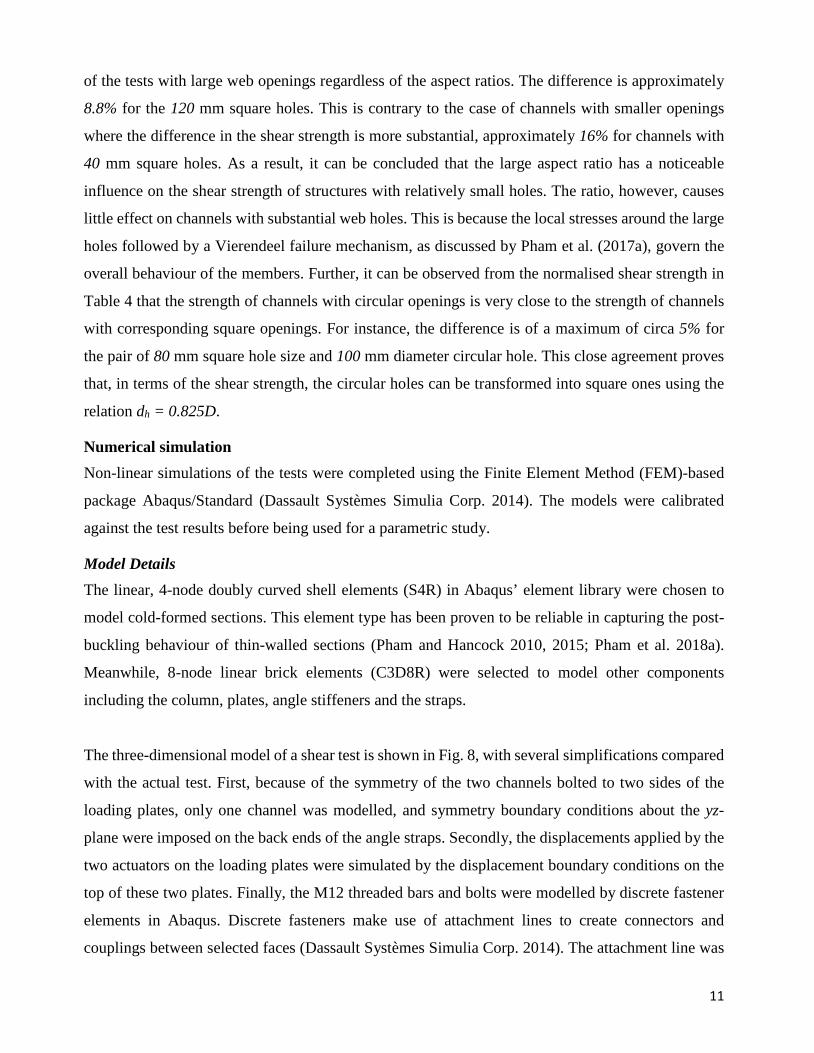
The three-dimensional model of a shear test is shown in Fig. 8, with several simplifications compared
with the actual test. First, because of the symmetry of the two channels bolted to two sides of the
loading plates, only one channel was modelled, and symmetry boundary conditions about the yz-
plane were imposed on the back ends of the angle straps. Secondly, the displacements applied by the
two actuators on the loading plates were simulated by the displacement boundary conditions on the
top of these two plates. Finally, the M12 threaded bars and bolts were modelled by discrete fastener
elements in Abaqus. Discrete fasteners make use of attachment lines to create connectors and
couplings between selected faces (Dassault Systèmes Simulia Corp. 2014). The attachment line was
12
created at the location of the bolt by projecting a point through all connected surfaces along the
direction of the bolts. A connector section was subsequently assigned to the attachment line. A
generic "cartesian + rotation" connector section was adopted, and a nonlinear elastic behaviour was
assigned for these connectors. This nonlinear elastic property was defined using the full force-
displacement curve obtained by bolted connection tests for cold-formed steel sections (Phan and
Rasmussen 2018). The actual diameters of the bolts (12 mm on the web and 10 mm on the flanges)
were accounted for by specifying the influence radius of the connectors. They are demonstrated by
the green circles in Fig. 8. The welded connection between the 20 mm web side plate as well as the
20 mm top and bottom plates and the column’s surface was modelled using a surface-to-surface tie
constraint which restrains all the translational and rotational degrees of freedom (DoF). The fixity at
the column base was simulated by imposing an “ENCASTRE” boundary condition which also
prevents all the DoFs. True stress-strain curves derived from engineering stress-strain curves obtained
by coupon tests are input to the material property of the cold-formed steel component to account for
material nonlinearity during analyses.
Validation of the FEM The accuracy of the finite element simulation is verified by both shear buckling and ultimate shear
strength analyses.
Firstly, eigenvalue buckling analyses were performed and the shear buckling loads were compared
with those obtained by the Spline Finite Strip Method (SFSM). The shape function for the SFSM is
expressed as the product of a polynomial and a spline function, typically a basic cubic B-3 spline
(Fan 1982; Fan and Cheung 1983). The method was applied by Eccher et al. (2008) for linear analysis
of perforated thin-walled structures. Pham (2017) compared the shear buckling loads of perforated
plates and of perforated channel sections with an aspect ratio of 1.0 obtained by both the SFSM and
the FEM. It was found that the two methods produce similar results despite different underlying shape
functions. Therefore, it is meaningful to use the SFSM to benchmark the FEM eigenvalue buckling
analysis.
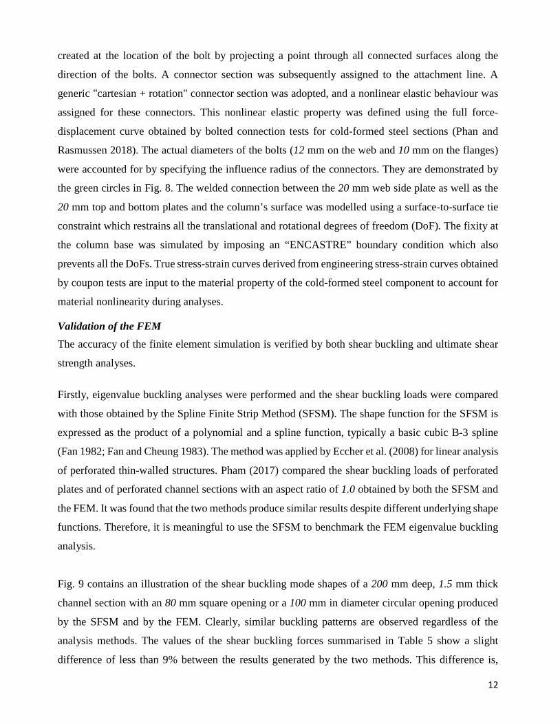
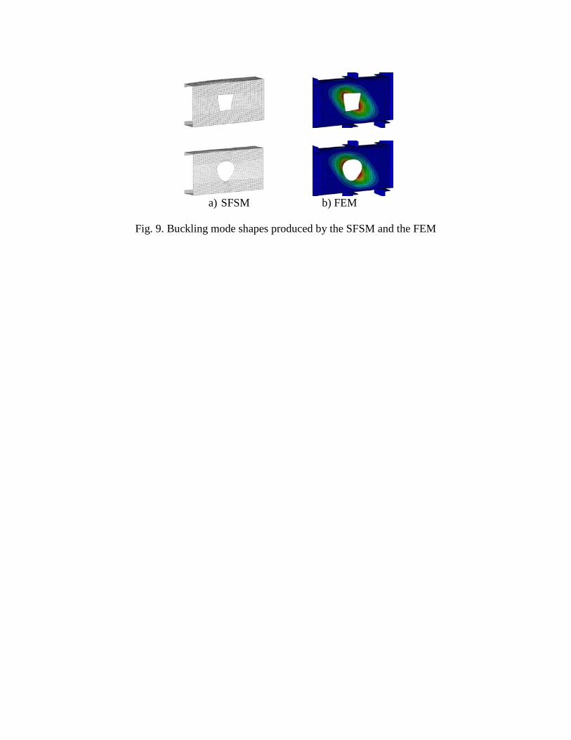
Fig. 9 contains an illustration of the shear buckling mode shapes of a 200 mm deep, 1.5 mm thick
channel section with an 80 mm square opening or a 100 mm in diameter circular opening produced
by the SFSM and by the FEM. Clearly, similar buckling patterns are observed regardless of the
analysis methods. The values of the shear buckling forces summarised in Table 5 show a slight
difference of less than 9% between the results generated by the two methods. This difference is,
13
however, expected since the FEM simulates the actual test rig which has a certain degree of rigidity
at the two ends of the shear span, as opposed to the idealised simply supported boundary conditions
used in the SFSM. Therefore, the FEM is considered as capable of capturing well the shear buckling
behaviour of cold-formed steel members.
Secondly, the ultimate shear strength analysis results including the peak shear forces, the shear failure
modes and the load versus displacement curves obtained by the FEM are compared with the
corresponding experimental outcomes. The actual dimensions of the test specimens as well as their
nonlinear material properties are input to the FE models. The sensitivity of the ultimate shear strength
to the initial geometrical imperfections is also investigated. The imperfections are incorporated into
the FE models using the normalised displacement fields obtained by buckling analyses scaled by a
factor of 0.15t or 0.64t where t is the thickness of cold-formed members. These scale factors have
been used consistently by Pham and Hancock (2010, 2012b) and Pham et al. (2014b). It was found
that the ultimate shear strengths are not sensitive to the initial geometrical imperfections, which is
also in line with the findings by the aforementioned researchers. The inclusion of the imperfections
only decreases the shear strengths by less than 1.1%. FE models with a scale factor of 0.64t produced
the shear strengths which are the best match with the experimental results, and thus it is used
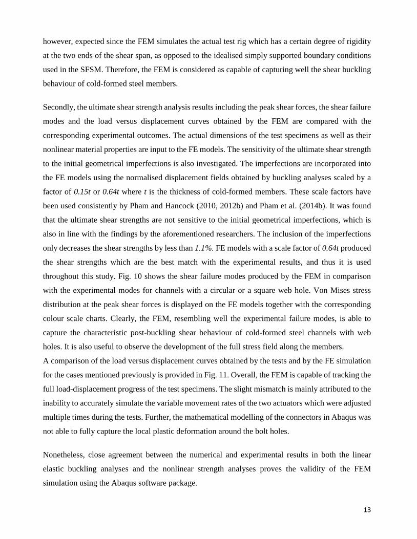
throughout this study. Fig. 10 shows the shear failure modes produced by the FEM in comparison
with the experimental modes for channels with a circular or a square web hole. Von Mises stress
distribution at the peak shear forces is displayed on the FE models together with the corresponding
colour scale charts. Clearly, the FEM, resembling well the experimental failure modes, is able to
capture the characteristic post-buckling shear behaviour of cold-formed steel channels with web
holes. It is also useful to observe the development of the full stress field along the members.
A comparison of the load versus displacement curves obtained by the tests and by the FE simulation
for the cases mentioned previously is provided in Fig. 11. Overall, the FEM is capable of tracking the
full load-displacement progress of the test specimens. The slight mismatch is mainly attributed to the
inability to accurately simulate the variable movement rates of the two actuators which were adjusted
multiple times during the tests. Further, the mathematical modelling of the connectors in Abaqus was
not able to fully capture the local plastic deformation around the bolt holes.
Nonetheless, close agreement between the numerical and experimental results in both the linear
elastic buckling analyses and the nonlinear strength analyses proves the validity of the FEM
simulation using the Abaqus software package.
14
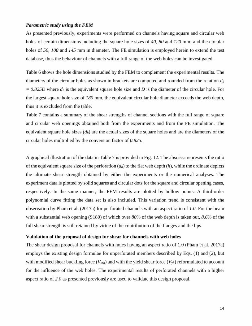
Parametric study using the FEM As presented previously, experiments were performed on channels having square and circular web
holes of certain dimensions including the square hole sizes of 40, 80 and 120 mm; and the circular
holes of 50, 100 and 145 mm in diameter. The FE simulation is employed herein to extend the test
database, thus the behaviour of channels with a full range of the web holes can be investigated.
Table 6 shows the hole dimensions studied by the FEM to complement the experimental results. The
diameters of the circular holes as shown in brackets are computed and rounded from the relation dh
= 0.825D where dh is the equivalent square hole size and D is the diameter of the circular hole. For
the largest square hole size of 180 mm, the equivalent circular hole diameter exceeds the web depth,
thus it is excluded from the table.
Table 7 contains a summary of the shear strengths of channel sections with the full range of square
and circular web openings obtained both from the experiments and from the FE simulation. The
equivalent square hole sizes (dh) are the actual sizes of the square holes and are the diameters of the
circular holes multiplied by the conversion factor of 0.825.
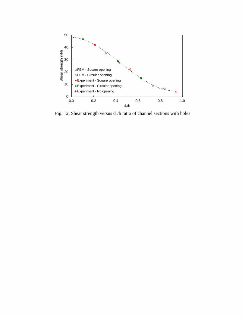
A graphical illustration of the data in Table 7 is provided in Fig. 12. The abscissa represents the ratio
of the equivalent square size of the perforation (dh) to the flat web depth (h), while the ordinate depicts
the ultimate shear strength obtained by either the experiments or the numerical analyses. The
experiment data is plotted by solid squares and circular dots for the square and circular opening cases,
respectively. In the same manner, the FEM results are plotted by hollow points. A third-order
polynomial curve fitting the data set is also included. This variation trend is consistent with the
observation by Pham et al. (2017a) for perforated channels with an aspect ratio of 1.0. For the beam
with a substantial web opening (S180) of which over 80% of the web depth is taken out, 8.6% of the
full shear strength is still retained by virtue of the contribution of the flanges and the lips.
Validation of the proposal of design for shear for channels with web holes The shear design proposal for channels with holes having an aspect ratio of 1.0 (Pham et al. 2017a)
employs the existing design formulae for unperforated members described by Eqs. (1) and (2), but
with modified shear buckling force (Vcrh) and with the yield shear force (Vyh) reformulated to account
for the influence of the web holes. The experimental results of perforated channels with a higher
aspect ratio of 2.0 as presented previously are used to validate this design proposal.
15
Table 8 contains a summary of the shear strengths predicted by the proposal compared with the
experimental shear strengths. In this table, Vn,T is the experimental shear strength of channels with
holes and with the shear span aspect ratio of 2.0; Vyh is the yield shear force determined in accordance
with Eqs. (7) and (8); Vcrh1 and Vcrh2 are the shear buckling forces determined by two methods namely
the eigen-buckling analysis using the computer package Abaqus, and the approximation using Eq.
(6) and (2), respectively. Details of the finite element eigen-buckling analysis to determine Vcrh1 was
discussed by Pham et al. (2017b). Associated shear strengths (Vn1 and Vn2) predicted by the design
proposal using the modified shear buckling forces (Vcrh1 and Vcrh2) and modified yield shear force
(Vyh) are included. The ratios of the test results (Vn,T) to the predicted values (Vn1 and Vn2) are
computed in conjunction with their mean values and coefficients of variation (CoV). It was found that
the proposed formulae predict reliably and consistently shear resistance of perforated sections
regardless of the methods used to determine the shear buckling forces, which is indicated by fairly
good mean values and low CoV. Further, shear buckling forces computed on the basis of Eq. (6)
slightly enhance the accuracy of the prediction which is credited to the favourable variation of the kv
approximation using Eq. (6) for this specific web opening range. This paper, however, uses Vcrh1
afterwards to evaluate the DSM design rules as these shear buckling forces are more accurate than
the approximate Vcrh2.
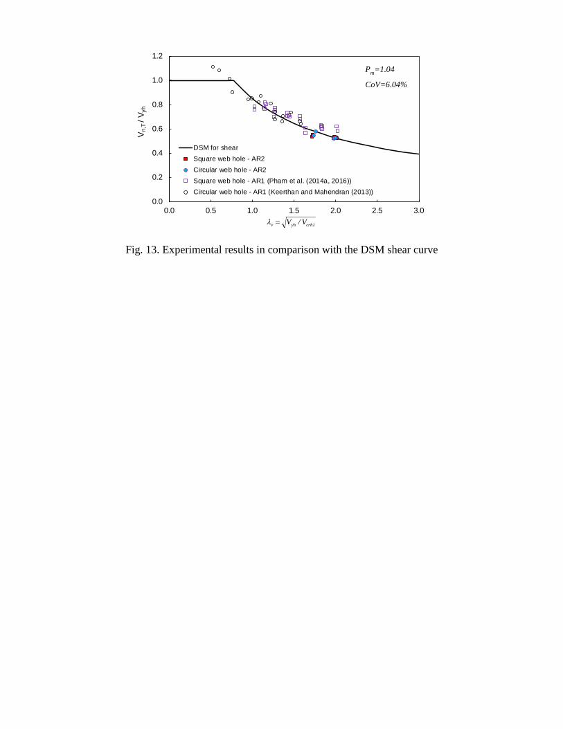
The test results are normalised and plotted against the design curve (Eq. 1) as shown in Fig. 13. The
abscissa depicts the section slenderness (λv), whereas the ordinate represents the ratio of the
experimental shear strength (Vn,T) to the modified shear yield force (Vyh). In this figure, the
experimental results of the members with an aspect ratio of 2.0, as shown in Table 8, are plotted as
the solid circles and solid squares for the tests with circular and square web holes, respectively. The
test results on perforated channels with an aspect ratio of 1.0 conducted by Pham et al. (2014a, 2016)
and by Keerthan and Mahendran (2013) are also included as hollow points. The graph clearly
indicates that the design curve for shear is able to predict well the shear strength of cold-formed steel
channel sections with circular and square web holes, and with aspect ratios up to 2.0. Furthermore,
the test results on longer shear spans seem to better follow the curve in comparison with the tests on
channels with a shear span aspect ratio of 1.0. The explanation is based on the fact that the former
test series was subjected to a minimal moment gradient, thus the shear strength was consistently close
to pure shear strength.
16
The mean value, standard deviation and the coefficient of variation of the Vn,T/ Vn1 ratios for 30 tests
of perforated channels with an aspect ratio of 1.0 (Pham et al. 2014a, 2016; Keerthan and Mahendran
2013) and 12 tests of perforated channels with an aspect ratio of 2.0 as presented in Table 8 are 1.04;
0.063 and 6.04%, respectively.
Comparison with the AISI S100-16 The AISI S100-16 Section G3 allows the shear strength of C-section webs with holes to be determined
in accordance with Section G2, with Vcr computed using Section G2.3, multiplied by the strength
reduction factor qs. It is therefore interpreted that Section G2.2 can be used to obtain the shear strength
of transversely stiffened channels using the elastic shear buckling force of the flat web alone, not the
shear buckling force of the full cross-section. The shear strength measured during the tests (Vn,T) is
compared with the strength predicted by the AISI S100-16 Section G3 (Vn,G3) in Table 9. It can be
seen that the predictions are close for channels with relatively small web openings. However, for
members with large web holes, the AISI provision for shear with holes over-estimates the shear
strength, as high as 72% above the experimental result. Further, the CoV of 16.4% indicates the
inconsistency of the prediction.
Calibration of the design proposal for channels with square and circular web holes
The resistance factor (φ) associated with the shear strength determined by the proposal as per Eqs.
(1) and (2) is computed using the AISI S100-16 Eq. K2.1.1-2 as follows:
( )2
Q2
PP2
F2
Mo VVCVVmmm ePFMC +++−= β
φφ (11)
where
Mm is the mean value of material factor with its associated coefficient of variation of VM; Fm is the mean value of fabrication factor with its associated coefficient of variation of VF; Pm is the mean value of professional factor taken as 1.04 as mentioned previously in Fig. 13; VP is the coefficient of variation of the test results, computed as the ratio of the standard deviation
of the test-to-predicted ratios to Pm. These two values are mentioned previously in Fig. 13, thus
VP takes a value of 0.061 but a minimum value of 0.065 is adopted as per the specification;
VQ is the coefficient of variation of the load effect, taken as 0.21 for the Load and Resistance Factor Design (LRFD) as specified by the AISI S100-16;
CP is the correction factor for sample size, ( )2m/mn11CP −
+= , where n=42 is the number
of tests, m=n-1=41 is the degree of freedom; as a result, CP=1.076;
17
For LRFD, the calibration coefficient ( )φC is taken as 1.52, and the target reliability index ( )oβ is
2.5 for structural members as per the AISI S100-16. The values of Mm, VM, Fm and VF are 1.192;
0.031; 1.000 and 0.010 respectively. These values are taken from 1,207 tests for steels from 1.0 mm
to 3.0 mm over a 12-month period from the mill of BlueScope Steel Ltd. (Pham and Hancock 2012a).
These are compared with the set of values extracted in the AISI S100-16 of 1.100; 0.100; 1.000 and
0.050 which show that statistical results obtained from the BlueScope Steel Ltd test program are
slightly higher and more consistent. With the target reliability index of 2.5, a resistance factor (φ) of
1.08 is obtained, which is greater than the factor of 0.95 in the AISI S100-16 and of 0.9 in the AS/NZS
4600:2018.
Conclusion This paper contains a summary of the proposal for shear design for cold-formed steel channels with
circular and square web openings having shear span aspect ratios up to 2.0. It is based on the
philosophy of the Direct Strength Method (DSM) but is general to the approach in the AISI S100-16
specification. The proposal is supported through the use of available test series of perforated channels
with a shear span aspect ratio of 1.0. It is further validated by a new experimental program on channels
with a shear span aspect ratio of 2.0 and with various square and circular opening sizes using a dual
actuator test setup. The dual actuator test rig minimizes applied bending moments along the shear
span, thus allowing ultimate shear strengths to be reached without premature flexural failures. Finite
element models were constructed, and they were calibrated using experimental data. The FEM was
used subsequently to expand the experimental database to investigate the variation of the shear
strength with respect to a wide range of web hole sizes. It was shown that once the shear buckling
force and the yield shear force are reformulated to include the influence of the web holes, the existing
design rules in the AISI S100-16 are capable of predicting reliably the shear strength of perforated
members with shear span aspect ratios up to 2.0. In addition, experimental shear strengths were used
to calibrate the design proposal for use with LRFD. It was confirmed that the current resistance factors
implemented in the AISI S100-16 and the AS/NZS 4600:2018 are sufficient.
ACKNOWLEDGEMENT
Funding provided by the Australian Research Council Discovery Project Grant DP160104640 has
been used to perform this project. The first author is supported by the University of Sydney
International Scholarship.
18
NOTATION
The following symbols are used in this paper: a = shear span (mm); bf = overall width of flange (mm); d = size of square web hole (mm); dh = equivalent size of square or circular opening (mm),
= actual size of the hole (d) for square hole, = 0.825D for the circular hole;
D = diameter of circular opening (mm); do = overall depth of lip (mm); d1 = clear depth of web (mm); h = depth of flat portion of web (mm); ho = overall depth of web (mm); kv = shear buckling coefficient; qs = shear strength reduction factor; t = thickness of cold-formed section (mm); Vcr = elastic buckling shear force of unreduced section (kN); Vcrh = elastic buckling shear force of section with web hole (kN); Vcrh1 = elastic buckling shear force of section with web hole computed by FE eigen-buckling
analysis (kN); Vcrh2 = elastic buckling shear force of section with web hole computed by approximation
method (kN); Vn,T = ultimate applied shear force obtained by experiment (kN); Vn = shear strength computed by the new design proposal (kN); Vn1 = shear strength computed by the new design proposal, using Vcrh1 (kN); Vn2 = shear strength computed by the new design proposal, using Vcrh2 (kN); Vvrd = shear yield force derived from a Vierendeel plastic mechanism (kN); Vy = shear yield force of unreduced section (kN); Vyh = shear yield force of section with web hole (kN);
REFERENCE AISI. (2012). “North American specification for the design of cold-formed steel structural
members.” Washington, D.C, U.S.A.
AISI. (2016). North American Specification for the Design of Cold-Formed Steel Structural
Members. Washington, D.C, U.S.A.
Basler, K., Yen, B.-T., Mueller, J. A., and Thürlimann, B. (1960). Web buckling tests on welded
plate girders, Part 3: Tests on plate girders subjected to shear. Fritz Engineering Laboratory,
Lehigh University, Bethlehem, Pennsylvania.
Dassault Systèmes Simulia Corp. (2014). “Abaqus/CAE.” Providence, RI, USA.
Eccher, G. (2007). “Isoparametric spline finite strip analysis of perforated thin-walled steel
structures.” The University of Sydney, Australia; University of Trento, Italy.
19
Eccher, G., Rasmussen, K. J. R., and Zandonini, R. (2008). “Linear elastic isoparametric spline
finite strip analysis of perforated thin-walled structures.” Thin-Walled Structures, 46, 242–260.
Eiler, M., Laboube, R., and Yu, W. (1997). Behavior of web elements with openings subjected to
linearly varying shear. Research report, University of Missouri-Rolla, Rolla, Missouri.
Fan, S. C. (1982). “Spline finite strip in structural analysis.” University of Hong Kong.
Fan, S. C., and Cheung, Y. K. (1983). “Static analysis of right box girder bridges by spline finite
strip method.” Proceedings of the Institution of Civil Engineers, 75(2), 311–323.
Keerthan, P., and Mahendran, M. (2013). “Experimental studies of the shear behaviour and strength
of lipped channel beams with web openings.” Thin-Walled Structures, 73, 131–144.
Pham, C. H. (2017). “Shear buckling of plates and thin-walled channel sections with holes.”
Journal of Constructional Steel Research, Elsevier Ltd, 128, 800–811.
Pham, C. H., Chin, Y. H., Boutros, P., and Hancock, G. J. (2014a). “The behaviour of cold-formed
C-sections with square holes in shear.” 22nd International Specialty Conference on Cold-
Formed Steel Structures, St. Louis, Missouri, U.S.A., 311–327.
Pham, C. H., Davis, A. F., and Emmett, B. R. (2014b). “Numerical investigation of cold-formed
lapped Z purlins under combined bending and shear.” Journal of Constructional Steel
Research, 95(0), 116–125.
Pham, C. H., and Hancock, G. J. (2009). “Shear buckling of thin-walled channel sections.” Journal
of Constructional Steel Research, Elsevier Ltd, Sydney, 65(3), 578–585.
Pham, C. H., and Hancock, G. J. (2010). “Numerical simulation of high strength cold-formed
purlins in combined bending and shear.” Journal of Constructional Steel Research, Elsevier,
66(10), 1205–1217.
Pham, C. H., and Hancock, G. J. (2012a). “Direct Strength Design of Cold-Formed C-Sections for
Shear and Combined Actions.” Journal of Structural Engineering, ASCE, 138(6), 759–768.
Pham, C. H., and Hancock, G. J. (2012b). “Tension field action for cold-formed sections in shear.”
Journal of Constructional Steel Research, 72, 168–178.
Pham, C. H., and Hancock, G. J. (2012c). “Elastic buckling of cold-formed channel sections in
shear.” Thin-Walled Structures, 61, 22–26.
Pham, C. H., and Hancock, G. J. (2015). “Numerical investigation of longitudinally stiffened web
channels predominantly in shear.” Thin-Walled Structures, 86, 47–55.
Pham, C. H., Pelosi, A., Earls, T., and Hancock, G. J. (2016). “Experimental and numerical
20
investigations of cold-formed C-sections with square holes in shear.” 23rd International
Specialty Conference on Cold-Formed Steel Structures, Baltimore, U.S.A.
Pham, S. H., Pham, C. H., and Hancock, G. J. (2017a). “Direct Strength Method of Design for
Channel Sections in Shear with Square and Circular Web Holes.” Journal of Structural
Engineering, 04017017, 1–8.
Pham, S. H., Pham, C. H., and Hancock, G. J. (2017b). “On the Design of Cold-Formed Steel
Beams with Holes in Shear Using the Direct Strength Method.” The 8th European Conference
on Steel and Composite Structures.
Pham, S. H., Pham, C. H., and Hancock, G. J. (2018a). “Experimental study of shear strength of
cold-formed channels with an aspect ratio of 2.0.” Journal of Constructional Steel Research,
Elsevier, 149, 141–152.
Pham, S. H., Pham, C. H., Rogers, C. A., and Hancock, G. J. (2018b). “Experimental studies of
cold-formed steel beams under uniform shear forces with minimal bending moments.” Eighth
International Conference on THIN-WALLED STRUCTURES ICTWS 2018, Lisbon,
Portugal.
Phan, D. K., and Rasmussen, K. J. R. (2018). “Cold-formed steel bolted and screw-fastened
connections in shear.” Eight International Conference on Thin-Walled Structures, Lisbon,
Portugal.
Schuster, R. M., Rogers, C. A., and Celli, A. (1995). “Research into cold-formed steel perforated C-
sections in shear.” Progress Report No. 1 of Phase I of CSSBI/IRAP Project, University of
Waterloo Waterloo, Ontario, Canada.
Shan, M.-Y., LaBoube, R., and Yu, W. (1994). “Behavior of web elements with openings subjected
to bending, shear and the combination of bending and shear.” Research report, University of
Missouri-Rolla, Rolla, Missouri.
Standards Australia. (2005). “AS 1391-2005. Metallic materials- Tensile testing at ambient
temperature.” Standards Australia, Sydney, Australia.
Standards Australia. (2011). “AS 1397-2011. Continuous hot-dip metallic coated steel sheet and
strip - Coatings of zinc and zinc alloyed with aluminium and magnesium.” Standards
Australia, Sydney, Australia.
Standards Australia. (2018). “AS4600 Cold-formed steel structures.” Standards
Australian/Standards New Zealand.
Figure Caption List
Fig. 1. Shear test on channel sections with web holes (Pham et al. 2014a, 2016)
Fig. 2. Practical location of plastic neutral axis on the top half of a net channel section
Fig. 3. Schematic diagram of the test setup
Fig. 4. Three-dimensional rendered images of the test setup
Fig. 5. Test specimen during loading
Fig. 6. Dimension notation of lipped channel section
Fig. 7. Shear failure of channels with square and circular web holes
Fig. 8. Finite element model of a shear test
Fig. 9. Buckling mode shapes produced by the SFSM and the FEM
Fig. 10. Shear failure modes by test and by FEM
Fig. 11. Comparison of load vs. displacement curves for perforated beam specimens
Fig. 12. Shear strength versus dh/h ratio of channel sections with holes
Fig. 13. Experimental results in comparison with the DSM shear curve
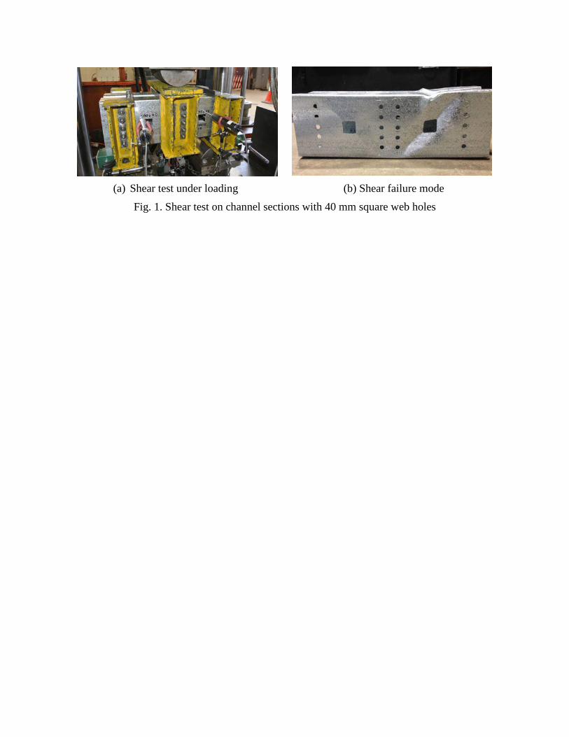
(a) Shear test under loading (b) Shear failure mode
Fig. 1. Shear test on channel sections with 40 mm square web holes
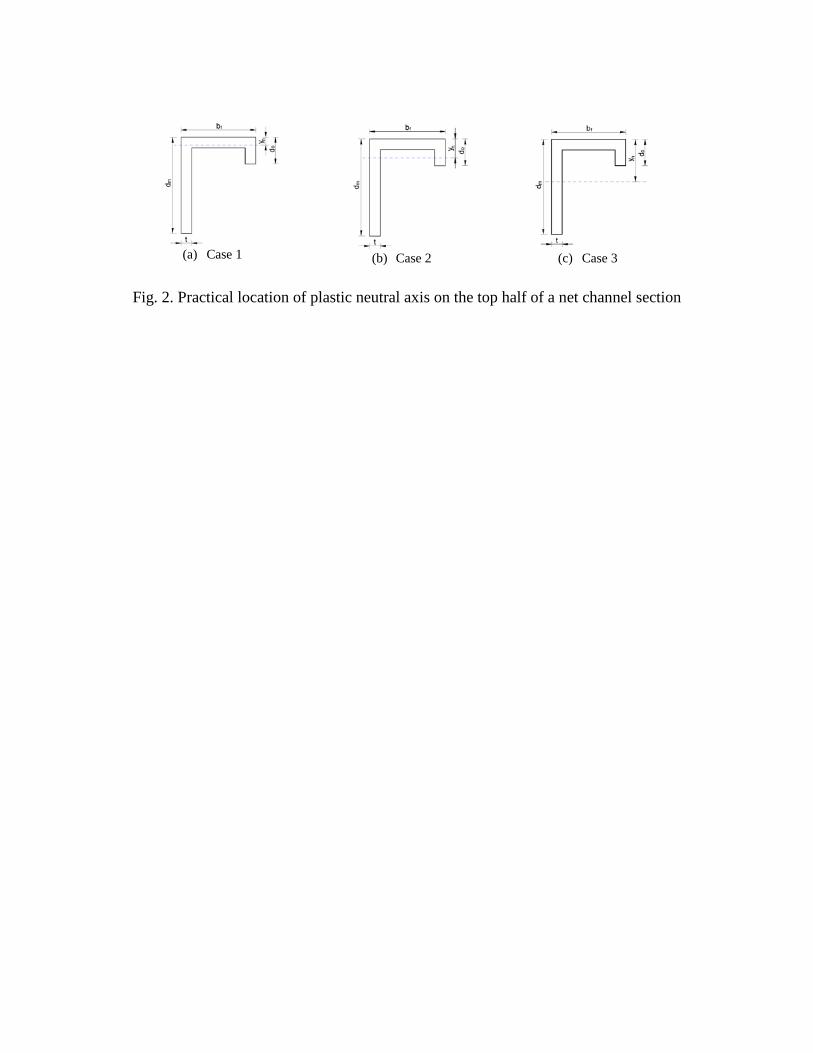
Fig. 2. Practical location of plastic neutral axis on the top half of a net channel section
(a) Case 1 (b) Case 2 (c) Case 3
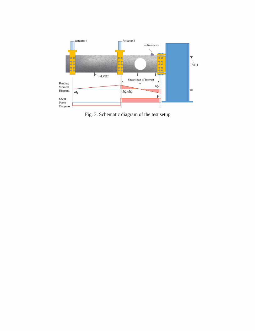
Fig. 3. Schematic diagram of the test setup
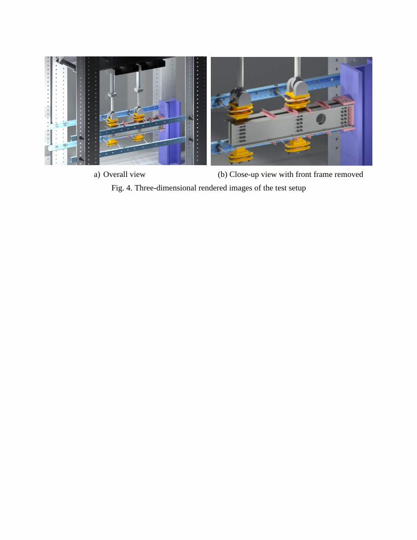
a) Overall view (b) Close-up view with front frame removed
Fig. 4. Three-dimensional rendered images of the test setup
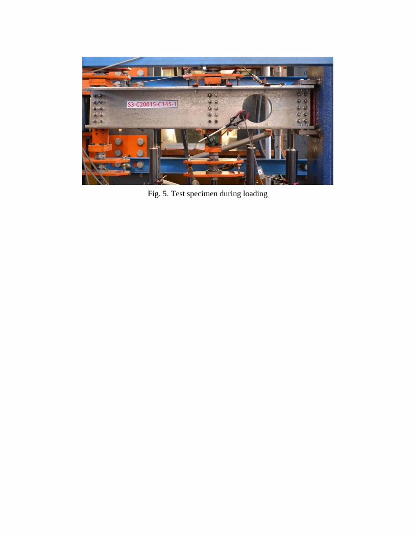
Fig. 5. Test specimen during loading
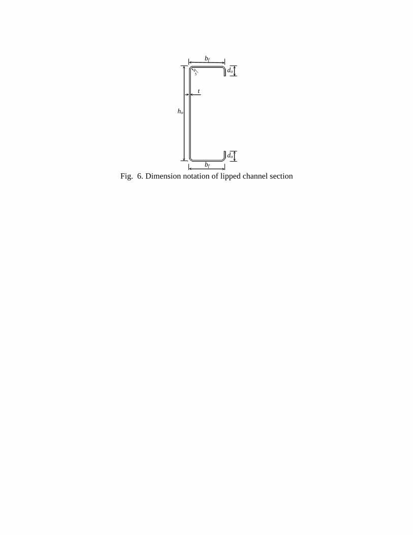
Fig. 6. Dimension notation of lipped channel section
ho
bf
bf
do
do
t
(a) Square hole size of 40 mm
(b) Square hole size of 120 mm
(c) Circular hole with a 50 mm diameter
(d) Circular hole with a 145 mm diameter
Fig. 7. Shear failure of channels with square and circular web holes
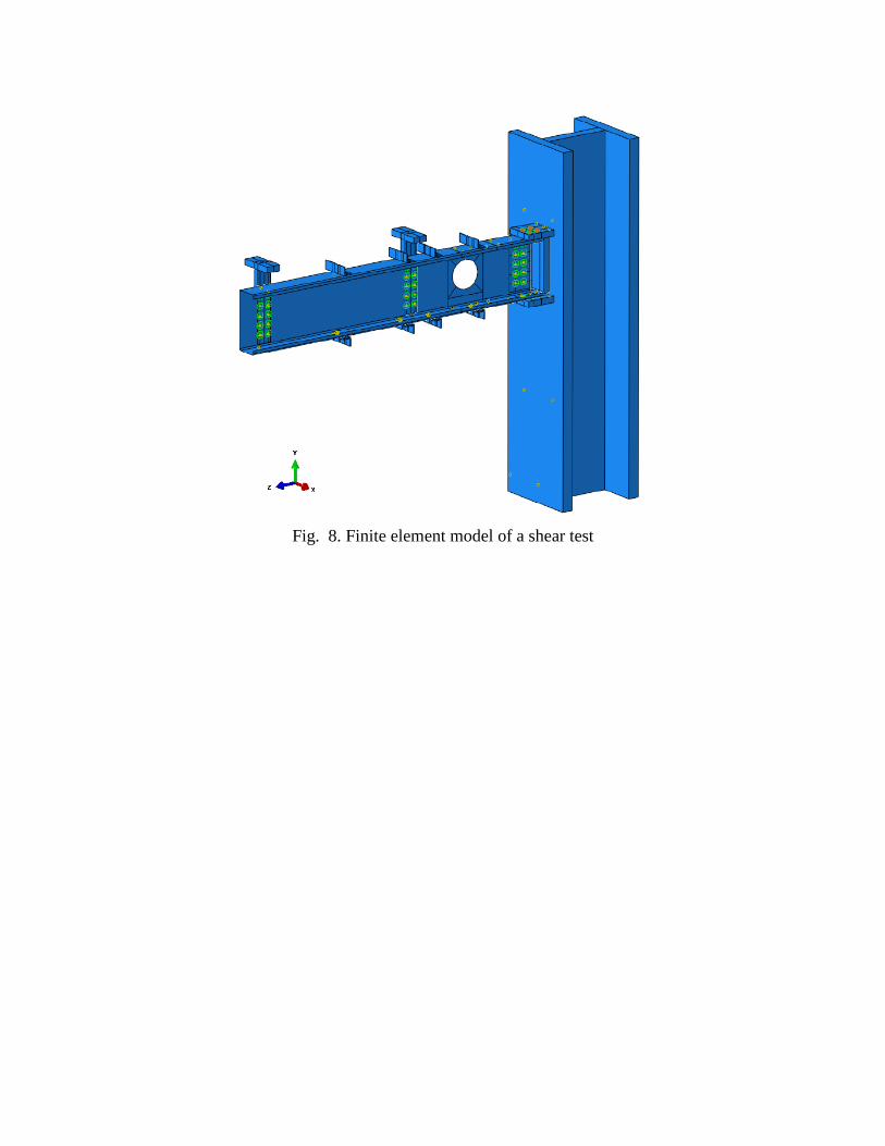
Fig. 8. Finite element model of a shear test
a) SFSM b) FEM
Fig. 9. Buckling mode shapes produced by the SFSM and the FEM
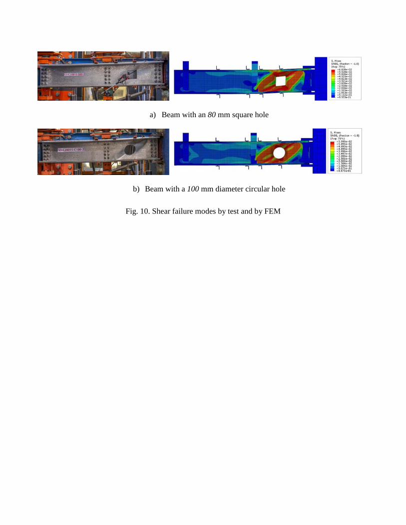
a) Beam with an 80 mm square hole
b) Beam with a 100 mm diameter circular hole
Fig. 10. Shear failure modes by test and by FEM
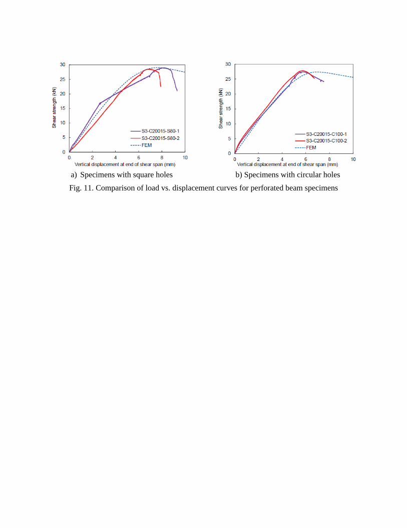
a) Specimens with square holes b) Specimens with circular holes
Fig. 11. Comparison of load vs. displacement curves for perforated beam specimens
0
10
20
30
40
50
0.0 0.2 0.4 0.6 0.8 1.0
She
ar s
treng
th (
kN)
dh/h
FEM - Square openingFEM - Circular openingExperiment - Square openingExperiment - Circular openingExperiment - No opening
Fig. 12. Shear strength versus dh/h ratio of channel sections with holes
0.0
0.2
0.4
0.6
0.8
1.0
1.2
0.0 0.5 1.0 1.5 2.0 2.5 3.0
Vn,
T / V
yhDSM for shearSquare web hole - AR2Circular web hole - AR2Square web hole - AR1 (Pham et al. (2014a, 2016))Circular web hole - AR1 (Keerthan and Mahendran (2013))
1crhyhv V/V=λ
Fig. 13. Experimental results in comparison with the DSM shear curve
Pm=1.04
CoV=6.04%
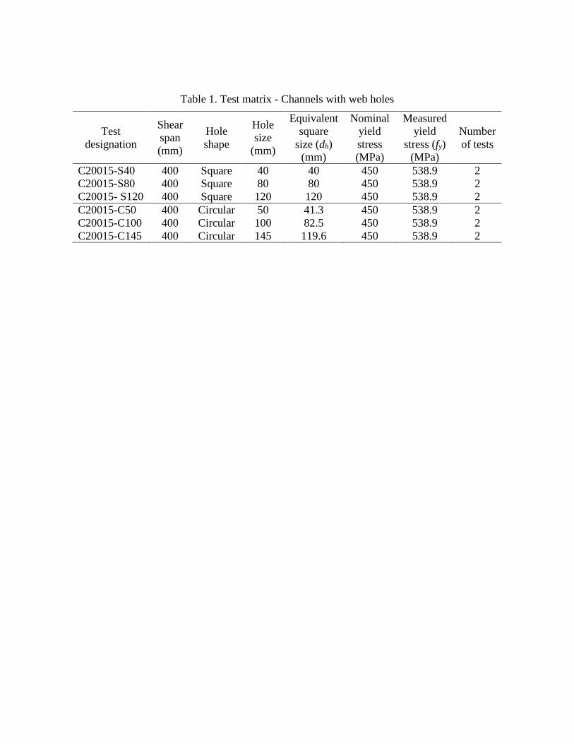
Table 1. Test matrix - Channels with web holes
Test designation
Shear span (mm)
Hole shape
Hole size
(mm)
Equivalent square
size (dh) (mm)
Nominal yield stress (MPa)
Measured yield
stress (fy) (MPa)
Number of tests
C20015-S40 400 Square 40 40 450 538.9 2 C20015-S80 400 Square 80 80 450 538.9 2 C20015- S120 400 Square 120 120 450 538.9 2 C20015-C50 400 Circular 50 41.3 450 538.9 2 C20015-C100 400 Circular 100 82.5 450 538.9 2 C20015-C145 400 Circular 145 119.6 450 538.9 2
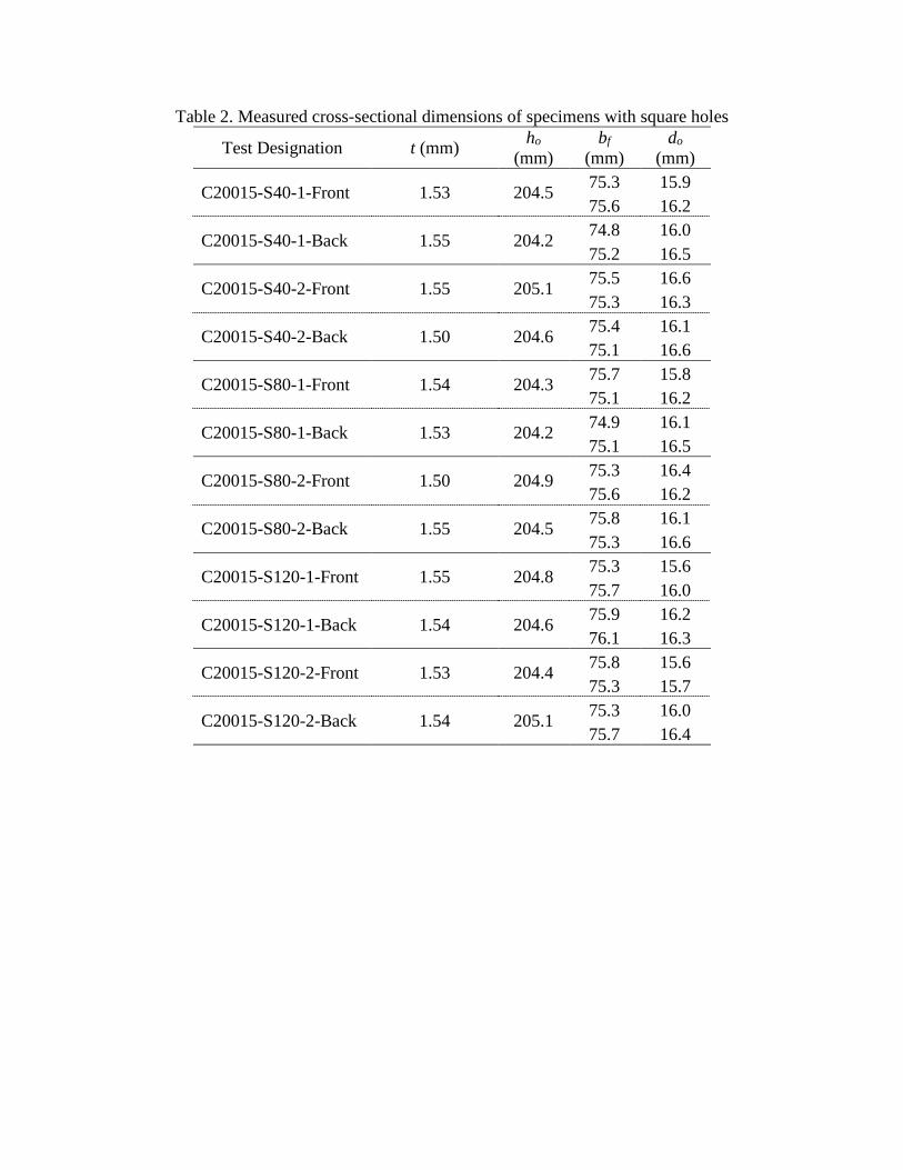
Table 2. Measured cross-sectional dimensions of specimens with square holes
Test Designation t (mm) ho (mm)
bf (mm)
do (mm)
C20015-S40-1-Front 1.53 204.5 75.3 15.9 75.6 16.2
C20015-S40-1-Back 1.55 204.2 74.8 16.0 75.2 16.5
C20015-S40-2-Front 1.55 205.1 75.5 16.6 75.3 16.3
C20015-S40-2-Back 1.50 204.6 75.4 16.1 75.1 16.6
C20015-S80-1-Front 1.54 204.3 75.7 15.8 75.1 16.2
C20015-S80-1-Back 1.53 204.2 74.9 16.1 75.1 16.5
C20015-S80-2-Front 1.50 204.9 75.3 16.4 75.6 16.2
C20015-S80-2-Back 1.55 204.5 75.8 16.1 75.3 16.6
C20015-S120-1-Front 1.55 204.8 75.3 15.6 75.7 16.0
C20015-S120-1-Back 1.54 204.6 75.9 16.2 76.1 16.3
C20015-S120-2-Front 1.53 204.4 75.8 15.6 75.3 15.7
C20015-S120-2-Back 1.54 205.1 75.3 16.0 75.7 16.4
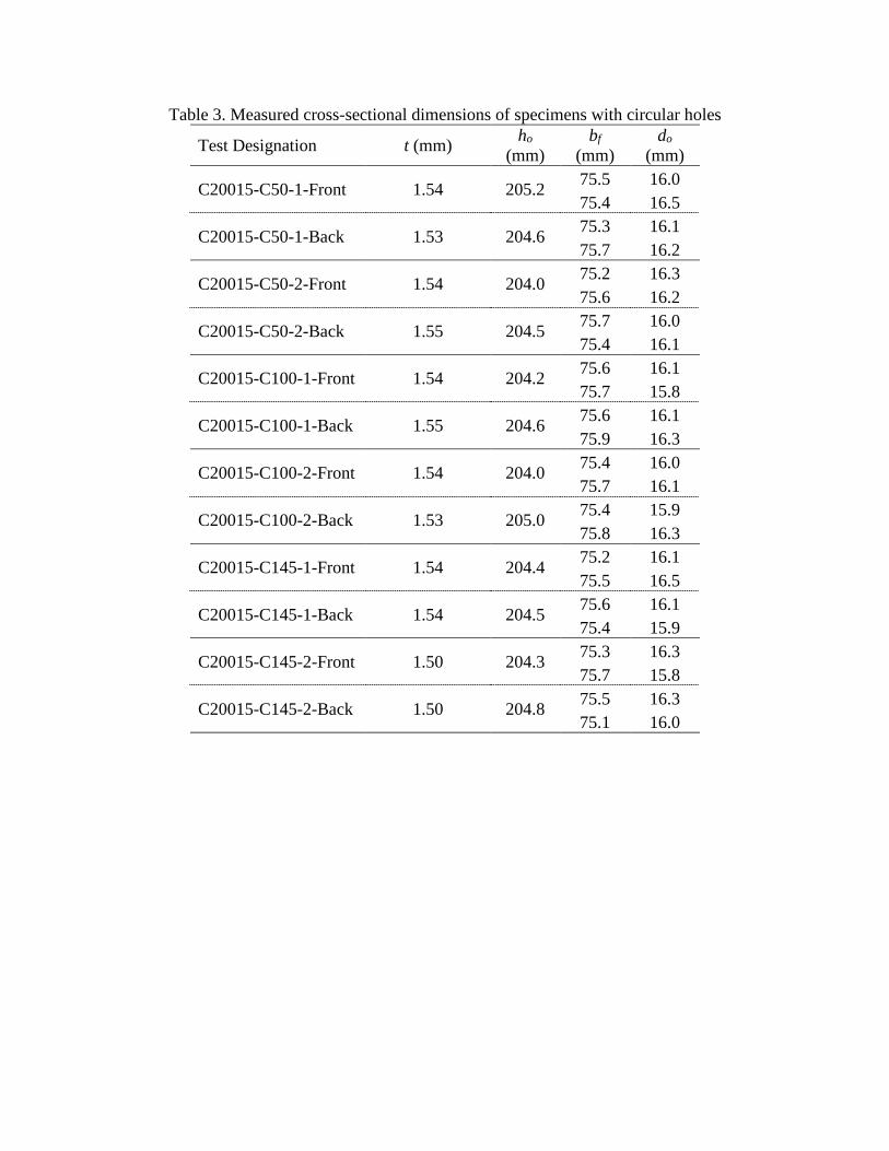
Table 3. Measured cross-sectional dimensions of specimens with circular holes
Test Designation t (mm) ho (mm)
bf (mm)
do (mm)
C20015-C50-1-Front 1.54 205.2 75.5 16.0 75.4 16.5
C20015-C50-1-Back 1.53 204.6 75.3 16.1 75.7 16.2
C20015-C50-2-Front 1.54 204.0 75.2 16.3 75.6 16.2
C20015-C50-2-Back 1.55 204.5 75.7 16.0 75.4 16.1
C20015-C100-1-Front 1.54 204.2 75.6 16.1 75.7 15.8
C20015-C100-1-Back 1.55 204.6 75.6 16.1 75.9 16.3
C20015-C100-2-Front 1.54 204.0 75.4 16.0 75.7 16.1
C20015-C100-2-Back 1.53 205.0 75.4 15.9 75.8 16.3
C20015-C145-1-Front 1.54 204.4 75.2 16.1 75.5 16.5
C20015-C145-1-Back 1.54 204.5 75.6 16.1 75.4 15.9
C20015-C145-2-Front 1.50 204.3 75.3 16.3 75.7 15.8
C20015-C145-2-Back 1.50 204.8 75.5 16.3 75.1 16.0
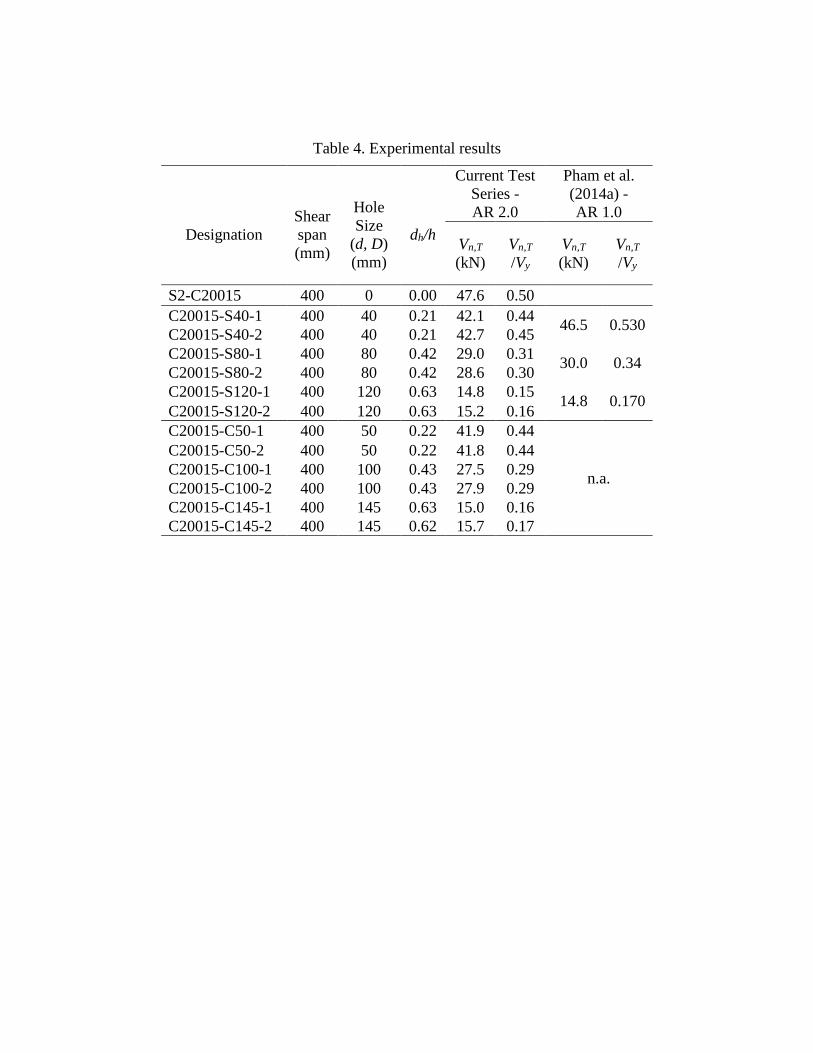
Table 4. Experimental results
Designation
Shear span (mm)
Hole Size
(d, D) (mm)
dh/h
Current Test Series - AR 2.0
Pham et al. (2014a) - AR 1.0
Vn,T (kN)
Vn,T /Vy
Vn,T (kN)
Vn,T /Vy
S2-C20015 400 0 0.00 47.6 0.50 C20015-S40-1 400 40 0.21 42.1 0.44 46.5 0.530 C20015-S40-2 400 40 0.21 42.7 0.45 C20015-S80-1 400 80 0.42 29.0 0.31 30.0 0.34 C20015-S80-2 400 80 0.42 28.6 0.30 C20015-S120-1 400 120 0.63 14.8 0.15 14.8 0.170 C20015-S120-2 400 120 0.63 15.2 0.16 C20015-C50-1 400 50 0.22 41.9 0.44
n.a.
C20015-C50-2 400 50 0.22 41.8 0.44 C20015-C100-1 400 100 0.43 27.5 0.29 C20015-C100-2 400 100 0.43 27.9 0.29 C20015-C145-1 400 145 0.63 15.0 0.16 C20015-C145-2 400 145 0.62 15.7 0.17
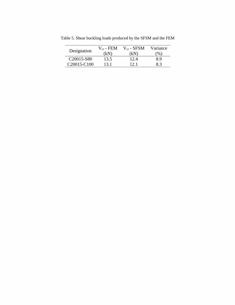
Table 5. Shear buckling loads produced by the SFSM and the FEM
Designation Vcr - FEM (kN)
Vcr - SFSM (kN)
Variance (%)
C20015-S80 13.5 12.4 8.9 C20015-C100 13.1 12.1 8.3
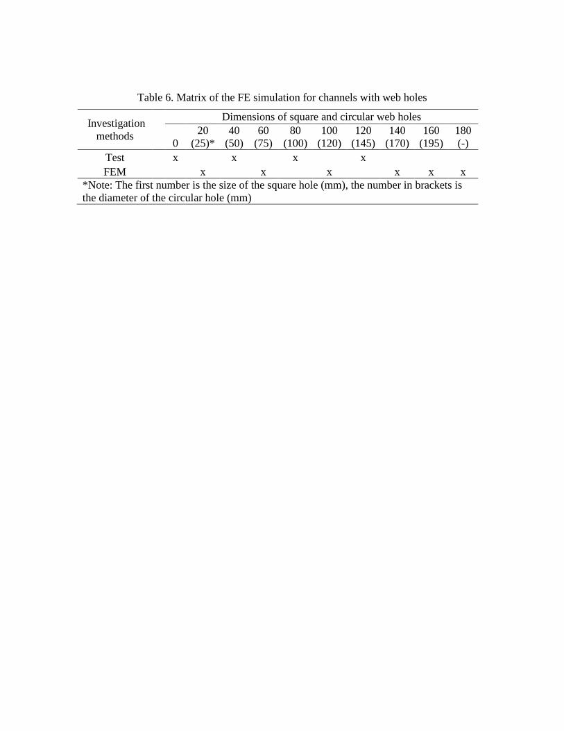
Table 6. Matrix of the FE simulation for channels with web holes
Investigation methods
Dimensions of square and circular web holes
0 20
(25)* 40
(50) 60
(75) 80
(100) 100
(120) 120
(145) 140
(170) 160
(195) 180 (-)
Test x x x x FEM x x x x x x
*Note: The first number is the size of the square hole (mm), the number in brackets is the diameter of the circular hole (mm)
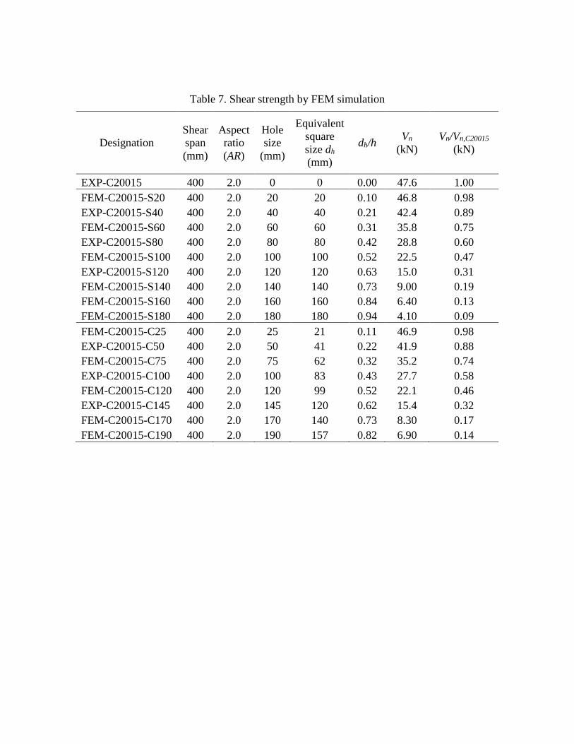
Table 7. Shear strength by FEM simulation
Designation Shear span (mm)
Aspect ratio (AR)
Hole size
(mm)
Equivalent square size dh (mm)
dh/h Vn (kN)
Vn/Vn,C20015 (kN)
EXP-C20015 400 2.0 0 0 0.00 47.6 1.00 FEM-C20015-S20 400 2.0 20 20 0.10 46.8 0.98 EXP-C20015-S40 400 2.0 40 40 0.21 42.4 0.89 FEM-C20015-S60 400 2.0 60 60 0.31 35.8 0.75 EXP-C20015-S80 400 2.0 80 80 0.42 28.8 0.60 FEM-C20015-S100 400 2.0 100 100 0.52 22.5 0.47 EXP-C20015-S120 400 2.0 120 120 0.63 15.0 0.31 FEM-C20015-S140 400 2.0 140 140 0.73 9.00 0.19 FEM-C20015-S160 400 2.0 160 160 0.84 6.40 0.13 FEM-C20015-S180 400 2.0 180 180 0.94 4.10 0.09 FEM-C20015-C25 400 2.0 25 21 0.11 46.9 0.98 EXP-C20015-C50 400 2.0 50 41 0.22 41.9 0.88 FEM-C20015-C75 400 2.0 75 62 0.32 35.2 0.74 EXP-C20015-C100 400 2.0 100 83 0.43 27.7 0.58 FEM-C20015-C120 400 2.0 120 99 0.52 22.1 0.46 EXP-C20015-C145 400 2.0 145 120 0.62 15.4 0.32 FEM-C20015-C170 400 2.0 170 140 0.73 8.30 0.17 FEM-C20015-C190 400 2.0 190 157 0.82 6.90 0.14
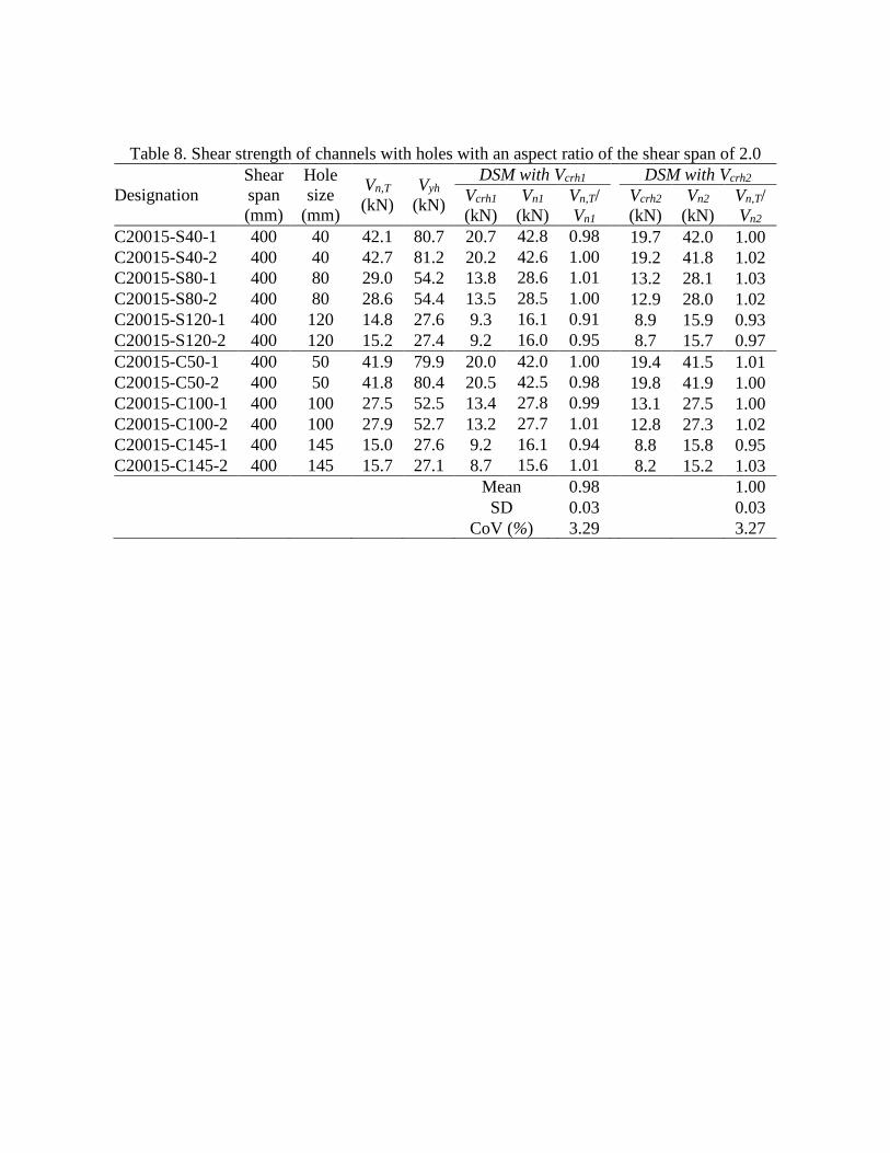
Table 8. Shear strength of channels with holes with an aspect ratio of the shear span of 2.0
Designation Shear span (mm)
Hole size
(mm)
Vn,T (kN)
Vyh (kN)
DSM with Vcrh1 DSM with Vcrh2 Vcrh1 (kN)
Vn1 (kN)
Vn,T/ Vn1
Vcrh2 (kN)
Vn2 (kN)
Vn,T/ Vn2
C20015-S40-1 400 40 42.1 80.7 20.7 42.8 0.98 19.7 42.0 1.00 C20015-S40-2 400 40 42.7 81.2 20.2 42.6 1.00 19.2 41.8 1.02 C20015-S80-1 400 80 29.0 54.2 13.8 28.6 1.01 13.2 28.1 1.03 C20015-S80-2 400 80 28.6 54.4 13.5 28.5 1.00 12.9 28.0 1.02 C20015-S120-1 400 120 14.8 27.6 9.3 16.1 0.91 8.9 15.9 0.93 C20015-S120-2 400 120 15.2 27.4 9.2 16.0 0.95 8.7 15.7 0.97 C20015-C50-1 400 50 41.9 79.9 20.0 42.0 1.00 19.4 41.5 1.01 C20015-C50-2 400 50 41.8 80.4 20.5 42.5 0.98 19.8 41.9 1.00 C20015-C100-1 400 100 27.5 52.5 13.4 27.8 0.99 13.1 27.5 1.00 C20015-C100-2 400 100 27.9 52.7 13.2 27.7 1.01 12.8 27.3 1.02 C20015-C145-1 400 145 15.0 27.6 9.2 16.1 0.94 8.8 15.8 0.95 C20015-C145-2 400 145 15.7 27.1 8.7 15.6 1.01 8.2 15.2 1.03
Mean 0.98 1.00
SD 0.03 0.03 CoV (%) 3.29 3.27
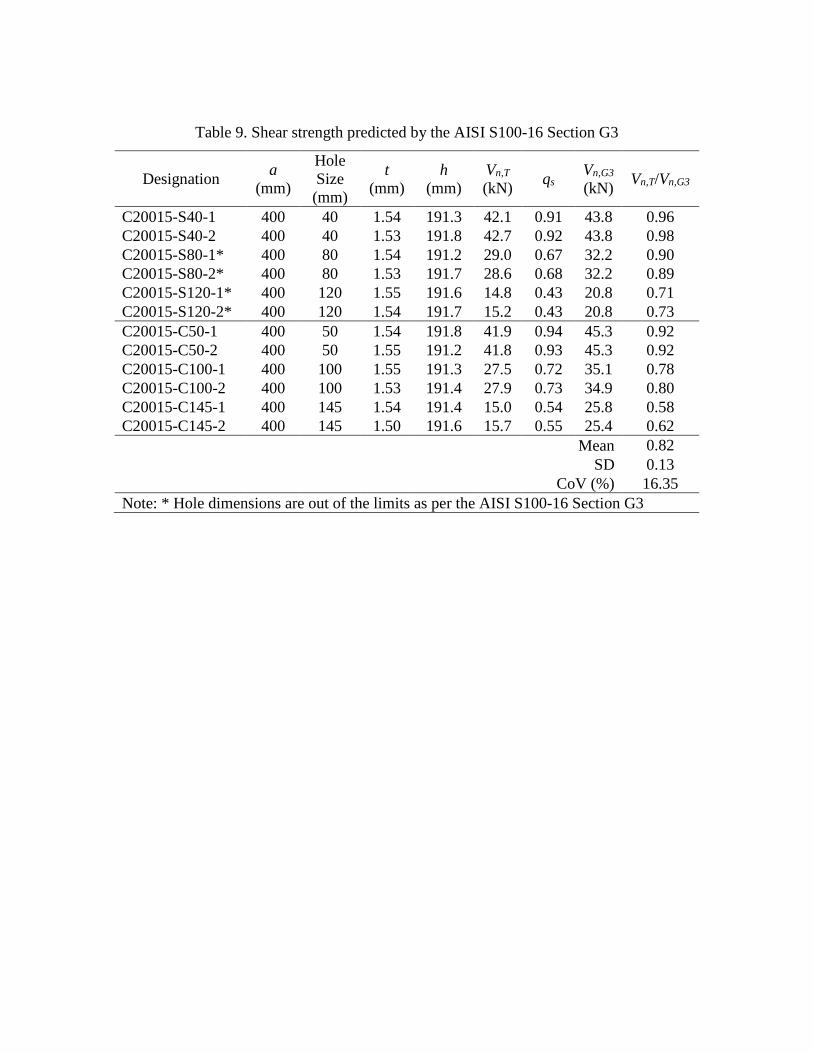
Table 9. Shear strength predicted by the AISI S100-16 Section G3
Designation a (mm)
Hole Size (mm)
t (mm)
h (mm)
Vn,T (kN) qs Vn,G3
(kN) Vn,T/Vn,G3
C20015-S40-1 400 40 1.54 191.3 42.1 0.91 43.8 0.96 C20015-S40-2 400 40 1.53 191.8 42.7 0.92 43.8 0.98 C20015-S80-1* 400 80 1.54 191.2 29.0 0.67 32.2 0.90 C20015-S80-2* 400 80 1.53 191.7 28.6 0.68 32.2 0.89 C20015-S120-1* 400 120 1.55 191.6 14.8 0.43 20.8 0.71 C20015-S120-2* 400 120 1.54 191.7 15.2 0.43 20.8 0.73 C20015-C50-1 400 50 1.54 191.8 41.9 0.94 45.3 0.92 C20015-C50-2 400 50 1.55 191.2 41.8 0.93 45.3 0.92 C20015-C100-1 400 100 1.55 191.3 27.5 0.72 35.1 0.78 C20015-C100-2 400 100 1.53 191.4 27.9 0.73 34.9 0.80 C20015-C145-1 400 145 1.54 191.4 15.0 0.54 25.8 0.58 C20015-C145-2 400 145 1.50 191.6 15.7 0.55 25.4 0.62 Mean 0.82 SD 0.13 CoV (%) 16.35 Note: * Hole dimensions are out of the limits as per the AISI S100-16 Section G3