SHEAR FRAME - STEP - Welcome · Laboratory equipment for shear experiments with consolidated ......
6
Revision state Version Date Document name Administrator 1.0 20.04.2011 ShearFrame manual_1.0 Dani Breitenstein SHEAR FRAME Laboratory equipment for shear experiments with consolidated sands and soils Completion: January 2010 Design & Fabrication: Dani Breitenstein ETH - Swiss federal institute of technology Soil and Terrestrial Environmental Physics (STEP) Universitätstrasse 16 CH-8092 Zürich Group Website: www.step.ethz.ch
Transcript of SHEAR FRAME - STEP - Welcome · Laboratory equipment for shear experiments with consolidated ......

Revision state
Version Date Document name Administrator
1.0 20.04.2011 ShearFrame manual_1.0 Dani Breitenstein
SHEAR FRAME Laboratory equipment for shear experiments with consolidated sands and soils
Completion: January 2010 Design & Fabrication: Dani Breitenstein ETH - Swiss federal institute of technology Soil and Terrestrial Environmental Physics (STEP) Universitätstrasse 16 CH-8092 Zürich Group Website: www.step.ethz.ch

Contents: 1. DEVICE AND ACCESSORY .......................................................................................................................... 3
1.1 INTRODUCTION ................................................................................................................................................ 3 1.2 DETAILS OF THE SHEAR BOX ........................................................................................................................... 4
2. SAFETY AND PRECAUTIONS ...................................................................................................................... 5
3. SPECIFICATION ............................................................................................................................................. 6

1. Device and Accessory
1.1 Introduction The process of shearing is the counter movement of two frames located on each other. The Shear Box is designed to measure acoustic emission. Therefore the maximal displacement is longer and the shear velocity can be adjusted in a broad range. The shear box can work either in a strain controlled mode with constant speed or in a load controlled mode with constant load. Additionally a piston is mount to the top frame to consolidate the observed soils or granular matter. The lower frame is longer (9) and mobile in one horizontal direction while the upper frame (10) has no degree of freedom. The upper frame’s bearings are force transducers to allow measuring all process forces in horizontal and vertical directions and correcting the calculated values for wall friction. The consolidation as well as the shear movement is measured and logged with displacement sensors. All measurements are analog are recorded with a data logger and displayed on a screen with a GUI programmed in LabView. At the bottom of the lower frame is a porous plate which allows setting suction up to 400mbar to the sample material. Suction matrix potential can be measured at two different depths below the shear plane via tensiometer. There are designated bore holes for connecting acoustic sensors inside of the soil.

1.2 Details of the Shear Box The lower Frame:
The lower frame is longer than the upper frame. Its bottom plate is a sintered stainless steel plate which is porous with an air entry value of approximately 200mbar (max. suction). The shear length can be reduced to a classical shear experiment with a separating wall so the area of the two frames is equaled (installed on picture).
Consolidation:
The consolidation stress is generated by air pressure and introduced with a pneumatic cylinder. The air pressure is adjusted with a pneumatic controller. A 3-way valve allows holding the position on a constant pressure, constant consolidation pressure or releasing pressure.
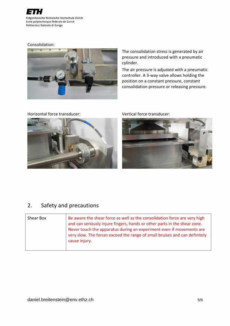
Horizontal force transducer: Vertical force transducer:
2. Safety and precautions
Shear Box Be aware the shear force as well as the consolidation force are very high and can seriously injure fingers, hands or other parts in the shear zone. Never touch the apparatus during an experiment even if movements are very slow. The forces exceed the range of small bruises and can definitely cause injury.

3. Specification
Shear Box: Upper frame:
- Area - Height Lower frame: - Area - Height - Max. suction Shearing: - Maximal displacement - Maximal shear stress - Minimal shear velocity - Maximal shear velocity Consolidation: - Maximal Pressure - Maximal Consolidation
150 x 150 72 400 x 150 72 200 250 250 0.1 200 125 25
mm mm mm mm mbar mm kN/m2 mm/min mm/min kN/m2
mm
Actuator: PERO
Spindle drive Strain controller GS - MOT A Force controller MEC 16 SCU Amplifier: SCU-Module SC-TF Software Perolog 3
Data logger: National Instruments
NI 9237 4-channel bridge module Ni cdaq chassis NI 9205 32-channel analog input module
Sensors: Displacement: - Shear Strain: - Dilation Force: - Horizontal: - Vertical: Consolidation Pressure:
Resistance, Novotechnik LWG 300LVDT LVDT, Inelta Typ ISDT50-K-2420 Beam lead cell, Omega LC703-100 Beam lead cell, Omega LC111-1K Keller LOE 2