Cold formed steel storage racks subjected to axial, shear ...
18
306 Cold formed steel storage racks subjected to axial, shear and bending interactions Selvakumar Thasan (Main and corresponding Author) Department of Civil Engineering, Government Polytechnic College Chennai 600 081 (India) [email protected] Senthil Rajendran Department of Civil Engineering, Anna University Chennai 600 025 (India) [email protected] Manuscript Code: 14010 Date of Acceptance/Reception: 05.08.2020/22.10.2019 DOI: 10.7764/RDLC.19.2.306 Abstract This research article aims to study the behaviour of expansion bolts under axial, shear and bending interaction of base plate connected cold formed steel storage racks. The uniaxial moment of rotation at the base plate connection was adopted to identify the ultimate moment of resistance and stiffness of the base plate connected to a concrete block using M10 grade anchor bolt at different range of axial loads ranging from 25% to 100% there by the design strength of upright profile was studied. The dimension of the upright and the base plate thickness has to be changed so that the extreme stability under various ranges of axial and transverse loads had been studied. Using finite element analysis software (Abaqus), a model has been created and designed to observe moment rotation characteristics, behaviour of base plate under simultaneous axial, shear and bending interactions and compared with experimental analysis. Comparative studies reveal that there was no failure in the concrete block and when the upright thickness increases, the stiffness and moment of the base plate increases despite having a similar cross section. An interaction equation was developed to find the stiffness and ultimate moment of resistance of the base plate connection. Keywords: expansion bolt, cold formed steel, moment of resistance, stiffness, distortion. Introduction In recent trends the development of structural steel using cold formed steel section plays a vital role in main frame construction of portal frames. These frames find its use in the construction of economic industrial, agricultural and residential buildings due to its lightweight and robustness. With the major claims in comparison with hot rolled steel profiles, cold formed steel possesses low cost, higly versatile with standard design procedures (AISI specification, 1996). Among various structural designs, industrial storage racks are the most prominent structures constructed using cold formed steel. It has been widely incorporated with the rational space utilization in warehouses and factories for goods storage (Freitas Freitas Souza & Silva, 2013). These rack systems have been classified as static and dynamic types. The adjustable pallet rack was found to be the commonly used static system. It consists of transversal beams and column upright which is grounded with base plate connections. This system provides the stability in down aisle direction. (Bajoria &Talikoti, 2006) The beams (stringers) have boxed cross-sections while columns (uprights) are open thin walled perforated to accept the tabs of beam end- connectors, which join beams and columns together without bolts or welds (Chung & Lp, 2003) (Figure 1). The rack members usually have perforations for assemblage, and are susceptible to the local and global instability phenomena characteristic of thin-walled structures. While the columns (uprights) present perforated open sections apt to accept the hooks of beam-end-connectors, which join beams and columns together without the need for bolts or welds. The structural deformation of the perforated thin walled columns is mainly dependent on the stiffness and moment at the base plate joints (Godley, Beale, & Feng, 2000; Godley, 2002). The behaviour of upright to base plate joints is typically non-linear. The column upright is connected to the concrete base with the use of base plate assemblies. This connection assembly need to transmit axial forces and moments to the ground. In contrast the moment and rotational stiffness directly depend on the axial force of the column (Freitas, Freitas, & Souza, 2005).
Transcript of Cold formed steel storage racks subjected to axial, shear ...

306
Cold formed steel storage racks subjected to axial, shear and bending interactions
Selvakumar Thasan (Main and corresponding Author)
Department of Civil Engineering, Government Polytechnic College Chennai 600 081 (India) [email protected]
Senthil Rajendran Department of Civil Engineering, Anna University Chennai 600 025 (India) [email protected] Manuscript Code: 14010 Date of Acceptance/Reception: 05.08.2020/22.10.2019 DOI: 10.7764/RDLC.19.2.306 Abstract This research article aims to study the behaviour of expansion bolts under axial, shear and bending interaction of base plate connected cold formed steel storage racks. The uniaxial moment of rotation at the base plate connection was adopted to identify the ultimate moment of resistance and stiffness of the base plate connected to a concrete block using M10 grade anchor bolt at different range of axial loads ranging from 25% to 100% there by the design strength of upright profile was studied. The dimension of the upright and the base plate thickness has to be changed so that the extreme stability under various ranges of axial and transverse loads had been studied. Using finite element analysis software (Abaqus), a model has been created and designed to observe moment rotation characteristics, behaviour of base plate under simultaneous axial, shear and bending interactions and compared with experimental analysis. Comparative studies reveal that there was no failure in the concrete block and when the upright thickness increases, the stiffness and moment of the base plate increases despite having a similar cross section. An interaction equation was developed to find the stiffness and ultimate moment of resistance of the base plate connection. Keywords: expansion bolt, cold formed steel, moment of resistance, stiffness, distortion.
Introduction In recent trends the development of structural steel using cold formed steel section plays a vital role in main frame construction of portal frames. These frames find its use in the construction of economic industrial, agricultural and residential buildings due to its lightweight and robustness. With the major claims in comparison with hot rolled steel profiles, cold formed steel possesses low cost, higly versatile with standard design procedures (AISI specification, 1996). Among various structural designs, industrial storage racks are the most prominent structures constructed using cold formed steel. It has been widely incorporated with the rational space utilization in warehouses and factories for goods storage (Freitas Freitas Souza & Silva, 2013). These rack systems have been classified as static and dynamic types. The adjustable pallet rack was found to be the commonly used static system. It consists of transversal beams and column upright which is grounded with base plate connections. This system provides the stability in down aisle direction. (Bajoria &Talikoti, 2006) The beams (stringers) have boxed cross-sections while columns (uprights) are open thin walled perforated to accept the tabs of beam end- connectors, which join beams and columns together without bolts or welds (Chung & Lp, 2003) (Figure 1). The rack members usually have perforations for assemblage, and are susceptible to the local and global instability phenomena characteristic of thin-walled structures. While the columns (uprights) present perforated open sections apt to accept the hooks of beam-end-connectors, which join beams and columns together without the need for bolts or welds. The structural deformation of the perforated thin walled columns is mainly dependent on the stiffness and moment at the base plate joints (Godley, Beale, & Feng, 2000; Godley, 2002). The behaviour of upright to base plate joints is typically non-linear. The column upright is connected to the concrete base with the use of base plate assemblies. This connection assembly need to transmit axial forces and moments to the ground. In contrast the moment and rotational stiffness directly depend on the axial force of the column (Freitas, Freitas, & Souza, 2005).

307
Figure 1. Typical cross section of cold form steel storage rack.
The base plate joint assembly can be bolted, brazed or semirigid connections with the column upright. The bolted connection is the most prominent fastener used in the construction of cold formed steel storage rack systems. Studies in Lewis (1991), Lim & Nethercot (2003), and Mc Donald, Heiyantuduwa & Rhodes (2008) showed that bolted moment connections between cold-formed steel members are feasible with high load bearing capacity of the structures up to 85% resistance offered by the connected members. The stiffness value of bolted joints would also decide the buckling length in member design (Vimal Mohan, Prabha, Rajasankar, Nagesh Iyer, Raviswaran, Nagendiran, & Kamalakannan, 2015). For slender structures like storage racks, sensitive to load effects, the looseness of the connection is an important factor that should be changed with robust design of semirigid joints as formulated by the RMI (Yancheng, & Young, 2014), AS 4086 (Cold-formed steel structure code AS/NZ 4600, 1996) and the BS 5950 (British Standard Institute, 1998). It is evident that the structural performance of base-plate to the upright connections depends significantly on the level of the axial load (Moen, & Schaffer, 2008; Prabha, Marimuthu, Saravanan, & Arul Jayachandran, 2010). The need for the base plate connections should be of simple design to construct and erect with enhanced stiffness and ductility. Various works related to bolted connections between cold formed steel upright and column bases with base plate connections (Yu, & Panyanouvong, 2013) Ahmad (2016) studied the industrial storage rack bolted base plate connection. Using finite element modelling, both the monotonic and cyclic responses of a typical floor connection have been investigated. Aleksander, & Lucja (2007) has analyzed that the steel storage pallet racks are three-dimensional framed structures. The aim is to find out the moment resistance and initial stiffness of storage rack joints. The results obtained using developed models are equated with the test results. Freitas, Souza, & Freitas (2010) analyzed the drive-in racks and their constituents on worldwide stability by a drive-in system. Base plate behavior is linear in the preliminary stage with high stiffness value. From a limit moment value, this stiffness fall off gradually, and the behavior of the base plate fluctuates. Baldassino, & Bernuzz (2000) had made a research on steel storage pallet racks, lateral stiffness in down-aisle direction is usually provided by base-plate connections and beam-to-column joints. It has been confirmed that the influence of the base plate joint on the rack and the need for test data of the column base restraint. Bucmys, & Sauciuvenas (2013) performed the behavior of cold formed steel connection. The results ensure that connection of the column base to a concrete slab does not modify the mechanical properties. Chung, & Lau (2001) explored a finite element model with three-dimensional solid elements were established the bearing failure of cold-formed steel bolted connections under shear. Gilbert, & Rasmussen (2011) performed the different components affecting the base plate stiffness and suggestion has been given for the location of the transducers when performing base plate tests to the EN 15512 British Standard Institute (2009). This investigation report is to determine the stiffness of the base plate. Elias, Neiva, Sarmanho, Alves, Castro, & Sarmanho (2018) performed an investigation of steel storage rack perforated uprights under axial compression. The study is to relate the ultimate loads of the experimental uprights by numerical and theoretical study. The theoretical values attained are lesser than the experimental ones and the ultimate loads, gained with the proposed buckling curve were less conservative than the DSM equations. Based on the works of Bernuzzi & Castiglioni (2008), this paper presents an extension of the structural behaviour of novel designed web stiffened and perforated cold-formed steel upright with bolted base plate connections, in particular to moment and rotational stiffness at the base plate joint connections with the upright. In order to adopt for the regression model in the proposed experimental work of thin walled web stiffened sections, an empirical design rule is proposed using Response surface method after validating against the finite element results using ABAQUS software. The proposed rule relates the rotational stiffness and moment of bolted connections directly with axial load, base plate thickness and profile thickness of cold-formed steel section through a regression coefficient.

308
Methodology Design of web stiffened Profile The web stiffened profile was designed with inclusion of perforations along the length of the upright. In accordance with the design consideration in section C3.4.1 as per AISI S 100-2007, the web crippling strength is calculated from Eq. (1 and 2). 𝑃𝑛𝑐=α𝑃𝑛 (1) Where, 𝑃𝑛𝑐= Nominal web crippling strength of C-section.
α = 1.34 (
𝐿𝑜ℎ⁄ )
0.26
0.009(ℎ𝑡⁄ )+0.3
≥ 1.0 (2)
𝐿0 = Over hang length measured from edge of bearing to the end of the member. h =Flat dimension of web measured in plane of web. t = Web thickness. 𝑃𝑛 = Nominal web crippling strength with end one flange loading as calculated by Eq.C3.4.1-1 and Tables C3.4.1-2 and C3.4.1-3. The main consideration in designing the upright of thin walled structures is to include the resistance towards buckling modes based on moment and stiffness functions. The uniform thickness of the upright sections and the relative offset from the neutral axis of their thin, wide flange elements make possible the assumption that their section properties, such as moment of inertia and section modulus, vary directly as the first power of thickness. Thus, in computation of section properties, section components may be treated as line elements. (AISI specification for the Design of cold formed steel structural members 1996). The AISC design guide is based on the resistance against plastic moment in the web, flange and lip elements of the cold formed section. The schematic view of the proposed cross-sectional web stiffened upright with perforations is shown in Figure 2 (a). Totally newly designed 20 specimens in six different profiles, whose cross section and thickness of upright having dimensions say (90 mm*70 mm*1.6 mm, 1.8 mm, 2 mm), (110 mm*75 mm*1.8 mm, 2.0 mm, 2.5 mm, 3.15 mm), (120 mm*100 mm*2.0 mm, 2.5 mm, 3.15 mm) and base plate having dimensions say (180 mm*110 mm*3.15 mm), (180 mm*125 mm*5 mm) (180 mm*150 mm*7.5 mm), (180 mm*150 mm*10 mm) are chosen for assessment. M10 grade anchor bolts are connected with an embedded length of 115 mm. Materials Two equal lengths of cold formed steel upright section (Figure 2 b and c) having around 4 times the width of the cold formed upright section connected with base plate is chosen. The base plates are standard sized connected with concrete block using an M10 grade anchor bolt. The grade of concrete block chosen is of the M20.
Figure 2. Upright and Base Plate.
(a) Schematic view of the Profile section
(b)Upright (c) Base Plate
Figure 3. Test setup, Experimental setup and Cross-sectional view of the experimental setup as per BS EN 15512-2009.

309
(a)Test setup as per BS EN 15512-2009
(b) Experimental setup – BS EN 15512-2009 (c) Cross sectional view of the experimental setup as per BS EN 15512-2009
Test Setup Base plate connections are semi-rigid where moment rotational characteristics are non – linear depending upon the factor say axial compression of the upright section and the bottom face of anchoring arrangement. The British Standard (BS EN 15512:2009) and the Australian Standard (AS 4084:2012) proposed an evaluation method, in which the moment and stiffness capacity has been computed under static loading as shown in Eq. (3 and 4). The key objective of this analytical research is to determine the behavior of the base plate of all six profiles which has been listed in Table 1 and Table 2 whose compressive strength is of 20 MPa, anchored using M 10 grade anchor bolt. The profile had been modelled using Abaqus and it is subjected to axial, shear and bending interactions, thereby the ultimate moment of resistance and stiffness of the base plate connection under different ranges of axial force say 25%, 50%, 75% and 100% shall be computed. Several analyses had been accomplished by fluctuating the thickness of the upright to 1.8 mm and 2 mm. The thickness has been varied to check whether there is any increase in the ultimate moment of resistance and stiffness of the base plate as shown in: Moment (Mbj) = (F2 l) /4+ (F1 𝜹) (3)
Rotation,Ѳbj=1
2[
𝛿3−𝛿4
𝑑12+
𝛿1−𝛿2
𝑑34] (4)
Where, 𝜹 = Mean displacement of the concrete cube, l = (l2+l1) /2, d34, d12= Distances between dial gauges. Steel rollers are placed at the bottom face of the concrete block to confirm negligible abrasion with a test setup on load situation.Two hydraulic jacks were implemented to apply the load in perpendicular and in crosswise direction simultaneously. Dial gauges are placed on the respective faces to identify the rotation of the column base and horizontal displacement of the concrete block as shown in Figure 3 (a).

310
The deformation of a base plate assembly subjected to an applied moment can be broken into four main components. Each of these deformations contributes to the total rotation of the upright and may not be prominent at the same time. The concrete block under the base plate will deform locally, the bracket of the base plate assembly will bend, the upright itself will bend and rotate relative to the base plate assembly, and a combination of flexure and yield lines will form in the base plate, allowing the assembly above the base plate to rotate as a rigid body. Concrete block shall have at least possible allowance of 50 mm with analogous faces all around the base plate. The cold form upright shall carve normal to their longitudinal axes and the faces of the block on which the upright shall remain parallel such that the axis of either upright coincides with the line of action of the load. Boundary conditions were allocated to the components of which lateral one direction is permissible and the remaining are ramped at the base of the concrete cube and at the end face of the upright and as well as at the end where base plate is connected, linear are ramped and rotations are allowed. Contact definitions assigned as tangential behavior as the base plate tend to rotate when axial cum lateral force is applied to the entire setup.Experimental test had been carried with different range of axial loads commencing from 25%, 50%, 75% and 100%. Using a hydraulic jack (F1), the load is applied to the upright profile commencing from 20kN simultaneously another load is applied at the center of concrete block transversely using hydraulic jack (F2) until the concrete block tend to crumble as shown in Figure 3 (b and c). Finite Element Modelling Using Abaqus, the above-mentioned profiles were designed as separate part with respect to the concept given in Figure 3. Properties were assigned for concrete cube, upright, base plate, and then assembled in the form, upright connected with the base plate and concrete cube on either face. Thereafter the entire model is subjected to 50 mm coarser meshing as defined in Figure 4 (a and b). Static step and timely increment at initial phase had been assigned for the entire assembly. Three reference nodes of which two at the center of upright on either face assigned as F1 (vertical direction) and the other at the center of the concrete cube assigned as F2 (horizontal direction) were chosen to impart load to the entire assembly such that it shall be distributed uniformly. Boundary conditions were assigned to the components of which lateral one direction is allowed and remaining are ramped at the base of the concrete cube and at the end face of the upright and also at the end where base plate is connected, linear are ramped and rotations are allowed. Contact definitions assigned as tangential behavior as the base plate tends to rotate when axial cum lateral force is applied to the entire assembly. Axial load (F1) commencing from 20 kN in terms of 25%, 50%, 75% and 100% in parallel connection with the increase in lateral load F2 is applied to observe the maximum distortion and also to compute the ultimate moment of resistance and stiffness capacity of the base plate. While applying the above condition to the rest of the profiles whose thickness varies, it was observed that, the ultimate moment of resistance and stiffness capacity of the base plate had been linearly increased and also the concrete cube indicates excessive distortion (lateral displacement) beyond ultimate load revealing the potential of the assembly.
Figure 4. Meshed views of the Assembly.
(a) Model view (b) Mesh view
311
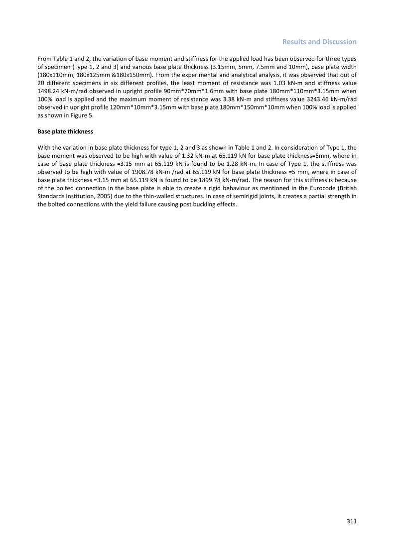
Results and Discussion From Table 1 and 2, the variation of base moment and stiffness for the applied load has been observed for three types of specimen (Type 1, 2 and 3) and various base plate thickness (3.15mm, 5mm, 7.5mm and 10mm), base plate width (180x110mm, 180x125mm &180x150mm). From the experimental and analytical analysis, it was observed that out of 20 different specimens in six different profiles, the least moment of resistance was 1.03 kN-m and stiffness value 1498.24 kN-m/rad observed in upright profile 90mm*70mm*1.6mm with base plate 180mm*110mm*3.15mm when 100% load is applied and the maximum moment of resistance was 3.38 kN-m and stiffness value 3243.46 kN-m/rad observed in upright profile 120mm*10mm*3.15mm with base plate 180mm*150mm*10mm when 100% load is applied as shown in Figure 5. Base plate thickness With the variation in base plate thickness for type 1, 2 and 3 as shown in Table 1 and 2. In consideration of Type 1, the base moment was observed to be high with value of 1.32 kN-m at 65.119 kN for base plate thickness=5mm, where in case of base plate thickness =3.15 mm at 65.119 kN is found to be 1.28 kN-m. In case of Type 1, the stiffness was observed to be high with value of 1908.78 kN-m /rad at 65.119 kN for base plate thickness =5 mm, where in case of base plate thickness =3.15 mm at 65.119 kN is found to be 1899.78 kN-m/rad. The reason for this stiffness is because of the bolted connection in the base plate is able to create a rigid behaviour as mentioned in the Eurocode (British Standards Institution, 2005) due to the thin-walled structures. In case of semirigid joints, it creates a partial strength in the bolted connections with the yield failure causing post buckling effects.

312
Table 1. Variation in moment and stiffness capacity of the specimen (A-J) for Type1, Type 2 and Type 3 Profile.
Analytical results on the behavior of steel storage racks subjected to axial, shear & bending interactions
S.No Type Description Specime
n Base Plate Axial Load
Experimental Results Analytical Results
M1
0 G
rad
e A
nch
or
Bo
lt -
2 N
os,
Em
bed
de
d L
engt
h -
11
5m
m
Moment kN-m
Stiffness (kN-m/rad)
Moment kN-m
Stiffness (kN-m/rad)
1
TYPE 1
90x70x1.6 mm
A 180x110x3.15m
m
25% 0.43 424.45 0.41 420.98
50% 0.72 717.76 0.688 712.23
75% 0.98 1296.57 1 1289.42
100% 1.03 1498.24 0.98 1464.28
2 90x70x1.8
mm B
180x110x3.15 mm
25% 0.44 305.67 0.41 300.27
50% 0.68 724.58 0.62 717.76
75% 1.03 1478.98 0.99 1456.64
100% 1.15 1798.89 1.08 1788.86
3 90x70x2.0
mm C
180x110x3.15 mm
25% 0.5 484.87 0.59 466.72
50% 0.78 776.98 0.80 770.54
75% 1.16 1609.78 1.19 1589.76
100% 1.28 1899.78 1.40 1892.26
4
TYPE 2
110x75x1.8mm
D 180x125x5.0
mm
25% 1.19 666.78 1.22 677.78
50% 1.44 1957.86 1.47 1964.46
75% 1.78 2044.49 1.82 2040.4
100% 1.96 2078.78 2.56 2072.28
5 110x75x2.0m
m E
180x125x5.0 mm
25% 1.28 862 1.29 857.7
50% 1.56 2099 1.52 2078.89
75% 1.88 2136 1.82 2103
100% 2.45 2206 2.21 2200

313
6 110x75x2.5m
m F
180x125x5.0 mm
25% 1.39 778.98 1.31 772.25
50% 1.59 2176.98 1.52 2156.78
75% 1.98 2205 1.88 2197
100% 2.3 2289 2.67 2269
7 110x75x3.15
mm G
180x125x7.5 mm
25% 1.37 1189.97 1.50 1124.64
50% 1.65 2767.67 1.76 2756.87
75% 1.97 2396.76 1.88 2377.57
100% 2.47 2539.97 2.28 2534.46
8
TYPE 3
120x100x2.0mm
H 180x150x7.5mm
25% 1.62 1401 1.56 1389
50% 1.78 2926 1.62 2882
75% 2.27 3118 2.16 3117
100% 3.19 3239 3.02 3229
9 120x100x2.5
mm I 180x150x7.5mm
25% 1.61 1400 1.66 1389
50% 1.82 2979 1.78 2969
75% 1.98 3113 1.85 3004
100% 3.11 3201 3.11 3117
10 120x100x3.15
mm J 180x150x7.5mm
25% 1.67 1319 1.77 1308
50% 2.1 2989 2.19 2978
75% 2.66 3039 2.36 3020
100% 3.26 3147 3.19 3122

314
Table 2. Variation in moment and stiffness capacity of the specimen (K-T) for Type1, Type 2 & Type 3 Profile
Analytical results on the behaviour of steel storage racks subjected to axial, shear & bending interactions
S.No Type Description Specime
n Base Plate Axial Load
Experimental Results Analytical Results
M1
0 G
rad
e A
nch
or
Bo
lt -
2 N
os,
Em
bed
de
d L
engt
h -
11
5m
m
Moment kN-m
Stiffness (kN-m/rad)
Moment kN-m
Stiffness (kN-m/rad)
1
TYPE 1
90x70x1.6 mm
K 180x110x5m
m
25% 0.48 430.1 0.45 410.32
50% 0.78 720.34 0.765 756.11
75% 1.01 1301.45 1.1 1201.33
100% 1.12 1520.12 1.255 1525.515
2 90x70x1.8
mm L
180x110x5 mm
25% 0.51 313.00 0.47 395.99
50% 0.74 733.73 0.77 816.10
75% 1.11 1499.43 1.19 1390.23
100% 1.23 1848.90 1.32 1796.68
3 90x70x2.0
mm M
180x110x5 mm
25% 0.53 487.76 0.51 470.65
50% 0.81 788.61 0.81 876.30
75% 1.16 1620.23 1.26 1504.45
100% 1.32 1908.78 1.41 1952.12
4
TYPE 2
110x75x1.8mm
N 180x125x7.5
mm
25% 1.28 678.28 1.52 807.15
50% 1.59 1964.57 1.95 2392.84
75% 1.91 2053.38 1.99 2135.1
100% 2.4 2087.3 2.52 2170.79
5 110x75x2.0m
m O
180x125x7.5 mm
25% 1.32 870 1.47 789.9
50% 1.66 2112.03 1.87 2245.08
75% 1.9 2150 1.97 2301
100% 2.53 2210.9 2.3 2378
6 110x75x2.5m
m P
180x125x7.5 mm
25% 1.41 789.6 1.38 910.98
50% 1.65 2188.78 1.88 2246.56
75% 2.1 2214.1 1.99 2297.43
100% 2.6 2346.8 2.75 2414.34

315
7 110x75x3.15
mm Q
180x125x7.5 mm
25% 1.43 1208.00 1.67 1389.20
50% 1.77 2845.41 2.12 3499.86
75% 2.16 2413.37 2.25 2485.77
100% 2.94 2604.95 3.06 2688.31
8
TYPE 3
120x100x2.0mm
R 180x150x10
mm
25% 1.65 1409.78 1.72 1356.8
50% 1.89 2987.23 2.1 2879
75% 2.47 3123.8 2.36 3067.45
100% 3.21 3234.96 2.97 3288.45
9 120x100x2.5
mm S
180x150x10mm
25% 1.68 1411.54 1.76 1358.68
50% 1.93 2991.45 2.17 2882.32
75% 2.5 3128.87 2.28 3068.48
100% 3.24 3239.96 3.11 3289.96
10 120x100x3.15
mm T
180x150x10mm
25% 1.73 1424.53 1.82 1362.28
50% 2.12 3005.67 2.24 2889.67
75% 2.76 3135.79 2.37 3077.86
100% 3.38 3243.46 3.22 3294.24

316
For Type 2, the base moment was observed to be high with value of 2.94 kN-m at 132.484 kN for base plate thickness =7.5 mm, where in case of base plate thickness =5mm at 132.484 kN is found to be 2.3 kN-m. In consideration of Type 2, the stiffness was observed to be high with value of 2604.95 kN-m /rad at 132.484 kN for base plate thickness =7.5 mm, where in case of base plate thickness =5mm at 132.484 kN is found to be 2539.97 kN-m/rad. The behaviour of base plate connections with the column upright resists the axial load based on the increase in thickness. The failure of the upright section could be observed in the outer region of the base plate with lesser thickness. This mechanism clarifies the bolted joint reaches the plastic yielding with the distortional buckling in the upright section. For Type 3, the base moment was observed to be high with value of 3.38 kN-m at 176.139 kN for base plate thickness =10 mm, where in case of base plate thickness =7.5 mm at 176.139 kN is found to be 3.26 kN-m. In case of Type 3, the stiffness was observed to be high with value of 3243.46 kN-m /rad at 176.139 kN for base plate thickness =10 mm, where in case of base plate thickness =7.5 mm at 132.484 kN is found to be 3147 kN-m/rad. Base plate width From Figure 5, it is noted for Type 1 and Type2 the base moment was observed to be high with value of 2.94 kN-m at 132.484 kN for a width of 125mm, where in case of width 110 mm at 65.119 kN is found to be 1.32 kN-m. In consideration of Type 1 and Type 2, the stiffness was observed to be high with value of 2604.95 kN-m /rad at 132.484 kN for a width of 125 mm, where in case of width 110 mm at 65.119 Kn is found to be 1908.78kN-m/rad. In Type 2 and Type3 the base moment was observed to be high with value of 3.38 kN-m at 176.139 kN for a width of 150 mm, where in case of width 125 mm at 132.484 kN is found to be 2.94 kN-m. The reason for the effective profile buckling reaches with the maximum lateral load observed when the maximum moment of the base plate joint is achieved by (Godley MHR, 2007). For Type 2 and Type 3, the stiffness was observed to be high with value of 3243.46 kN-m /rad at 176.139 kN for a width of 150 mm, where in case of width 125 mm at 132.484 kN is found to be 2604.95 kN-m/rad. In case of Type3 and Type1 the base moment was observed to be high with value of 3.38 kN-m at 176.139 kN for a width of 150 mm, where in case of width 110 mm at 65.119 kN is found to be 1.32 kN-m. Alternatively, for Type 3 and Type 1, the stiffness was observed to be high with value of 3243.46 kN-m /rad at 176.139 kN for a width of 150 mm, where in case of width 110mm at 65.119 kN is found to be 1908.78 kN-m/rad.
Figure 5. Analytical Graph for All Combination.

317

318
Profile thickness In consideration of Type 1, the Profile thickness 2 mm was observed to be high base moment with value of 1.32 kN-m at 65.119 kN, where in case of profile thickness of 1.8 mm at 65.119 kN is found to be 1.23 kN-m and profile thickness 1.6 mm at 65.119 kN is found to be 1.12 kN-m. For Type 1, the Profile thickness 2mm was observed to be high stiffness with value of 1908.78 kN-m/rad at 65.119 kN, where in case of profile thickness 1.8 mm at 65.119 Kn is found to be 1848.90 kN-m/rad and profile thickness 1.6 mm at 65.119 Kn is found to be 1520.12 kN-m/rad. In consideration of Type 2, the Profile thickness 3.15 mm was observed to be high base moment with value of 2.94 kN-m at 132.484 kN, where in case of profile thickness 2.5 mm, 2.0 mm, 1.8 mm at 132.484 kN is found to be 2.6 kN-m,2.53 kN-m, 2.4 kN-m respectively. In consideration of Type 2, the Profile thickness 3.15 mm was observed to be high stiffness with value of 2604.95 kN-m/rad at 132.484 kN, where in case of profile thickness 2.5 mm, 2.0 mm, 1.8 mm at 132.484 kN is found to be 2346.8 kN-m/rad, 2210.92 kN-m/rad, 2087.5 kN-m/rad, respectively. In case of Type 3, the Profile thickness 3.15mm was observed to be high base moment with value of 3.38 kN-m at 176.139 kN, where in case of profile thickness 2.5mm at 176.139 kN is found to be 3.24 kN-m and profile thickness 2 mm at 176.139 kN is found to be 3.21 kN-m. For Type 3, the Profile thickness 3.15 mm was observed to be high stiffness with value of 3243.46 kN-m/rad at 176.139 kN, where in case of profile thickness 2.5 mm at 176.139 kN is found to be 3239.96 kN-m/rad and profile thickness 2 mm at 176.139 kN is found to be 3234.96 kN-m/rad. In order to evaluate the Response Surface Methodology (RSM) mostly employs statistical regression method as it is practical, economical and relatively easy to use. In order to model and analyse the effect of each variables Base plate thickness, Base plate width, Profile thickness and Axial Load towards the objective functions Moment and Rotational stiffness, design of experiments for a number of parameters should be developed. This quadratic model usually refers as a regression model. Three level, four factors are used in the experiment. Therefore, the BBD required 16 numbers of experiments with 2 repetitions the two levels (high, +1 and low, −1) and coded level (0) which is the midpoint between the high and low levels can be seen in the Table 3. The proposed model was analyzed using Design expert software.

319
First, the coefficient of determination or denoted as R2 is evaluated. The R2 value is a statistical measure of how close the predicted data to the fitted regression line. The regression interaction equation has been generation with the measured coefficients with y as function of the output responses (Moment and rotational stiffness) which related to linear algebraic equation in terms of x which is the coded factor of input parameters (Profile volume, base plate thickness and axial load). Regression model The Predicted R² of 0.6651 is not as close to the Adjusted R² of 0.9947 as one might normally expect; i.e. the difference is more than 0.2 as shown in Table 4-7. A ratio of 9.871 indicates an adequate signal. Hence the proposed model is found to be significant with the experimental and analytical data. The coefficients are adjustments around that average based on the factor settings as shown in Table 4-7. The Box cox plot is shown in Figure 5 describes the statistical intervals based on normality. To define the normality of the real set data in transformation function. The real set data are not normally distributed and transformed into a normal distribution using the Box-Cox transformation. The Box-Cox transformation is Yλ where λ is value between -3 and 3.
Table 3. Design of experiments based on Box benkhen Design.
Std Run A: Profile Volume B: Base plate thickness C: Axial Load Moment Stiffness m3 mm kN kN-m kN-m/rad
8 1 0.378 6.575 195.6 3.12 3152.65 10 2 0.19404 10 13.101 1.94 3005.67 6 3 0.378 6.575 13.101 1.24 2604.35 5 4 0.01008 6.57 13.101 1.24 2604.35
17 5 0.19404 6.575 104.35 2.87 2991.35 7 6 0.01008 6.575 195.6 3.12 3152.65 2 7 0.378 3.15 104.35 1.98 1589.76
11 8 0.19404 3.15 195.6 2.46 1788.35 3 9 0.01008 10 104.35 2.93 3128.62 9 10 0.19404 3.15 13.101 0.43 424.45 4 11 0.378 10 104.35 2.93 3128.62
12 12 0.19404 10 195.6 3.22 3294.24 1 13 0.01008 3.15 104.35 1.98 1589.76
13 14 0.19404 6.575 104.35 2.87 2991.35 14 15 0.19404 6.575 104.35 2.87 2991.35 15 16 0.19404 6.575 104.35 2.87 2991.35 16 17 0.19404 6.575 104.35 2.87 2991.35
Figure 5. Box cox plot for (a) base moment, (b) rotational stiffness.
(a) Base Moment (b) Rotational Stiffness
The Lambda value is set at 1.8. The blue line indicates the transformation function for the current design space. In this case it points to a value of 1 for λ, which symbolizes the power applied to your response values. The green line indicates the best lambda value, As shown in Figure 5 (b) the blue line falls within the green line predicting the data’s in the optimal zone, so no change is necessary in the response transformation.

320
Contour plot in Figure 6 shows the interaction between Profile volume and Axial Load on the Moment. Profile volume is the significant factor responsible for effective Moment. At higher Base plate thickness, the quantum stiffness of which holds the in the column upright resulting in better Moment. At Profile volume of 0.374 m3, and Axial Load of 195.6 kN, the optimum value of 3.46 kN-m is noticed. Contour plot in Figure 6 shows the interaction between Profile volume, base plate thickness and Axial Load on Stiffness. At Profile volume 0.28602 m3, Base plate thickness of 5.89 mm and axial load of 104.35 kN, the Stiffness value is found to be increased with 3243.46 kN-m/rad.
Figure 6. Contour plots of base moment and rotational stiffness for Type1, 2 &3 upright sections.
Type 1 (Moment) Type 2 (Moment) Type 3 (Moment)
Type 1 (Stiffness) Type 2 (Stiffness) Type 3 (Stiffness)
Table 4. Interaction Equation - Experimental moment and stiffness for specimen A to J.
Specimen Moment for specimen A to J Stiffness for specimen A to J
Interaction Equation R2 Value Interaction Equation R2 Value
A y = 0.86x + 0.31 R² = 0.9619 y = 1540.5x + 30.21 R² = 0.9704
B y = 1.012x + 0.265
R² = 0.9679 y = 2149.4x - 244.58 R² = 0.9795
C y = 1.088x + 0.275 R² = 0.9815 y = 2037.9x - 72.325 R² = 0.9574
D y = 1.472x + 0.875 R² = 0.9863 y = 1726.3x + 616.91 R² = 0.6706
E y = 1.548x + 0.885 R² = 0.9578 y = 1624.3x + 820.56 R² = 0.6604
F y = 1.608x + 0.935 R² = 0.978 y = 1878.8x + 710.59 R² = 0.6835
G y = 1.9686x + 0.8438 R² = 0.9579 y = 1503.5x + 1328.2 R² = 0.4438
H y = 2.104x + 0.99 R² = 0.9557 y = 2244.8x + 1285.9 R² = 0.7118
I y = 2.1x + 1.025 R² = 0.9575 y = 2249.1x + 1287.3 R² = 0.7119
J y = 2.236x + 1.1 R² = 0.9893 y = 2234.8x + 1305.6 R² = 0.7076

321
Table 5. Interaction Equation - Analytical moment and stiffness for specimen A to J.
Specimen
Moment for specimen A to J Stiffness for specimen A to J
Interaction Equation R2 Value Interaction Equation R2 Value
A y = 1.1x + 0.205 R² = 0.9783 y = 1516.3x + 25.618 R² = 0.9965
B y = 1.1928x + 0.1895
R² = 0.9679 y = 1910.5x - 94.3 R² = 0.9954
C y = 1.2589x + 0.2109 R² = 0.9692 y = 2029x - 67.26 R² = 0.9934
D y = 1.216x + 1.235 R² = 0.9181 y = 1533.3x + 918.17 R² = 0.4699
E y = 1.036x + 1.255 R² = 0.9565 y = 1928.1x + 723.44 R² = 0.6686
F y = 1.688x + 0.945 R² = 0.9262 y = 1824.4x + 827.09 R² = 0.6922
G y = 1.7166x + 1.2017 R² = 0.9153 y = 1153.3x + 1795 R² = 0.1832
H y = 1.604x + 1.285 R² = 0.9707 y = 2393.4x + 1152.1 R² = 0.776
I y = 1.664x + 1.29 R² = 0.9 y = 2392x + 1154.9 R² = 0.7753
J y = 1.732x + 1.33 R² = 0.906 y = 2393.6x + 1160 R² = 0.7739
Table 6. Interaction Equation - Experimental moment and stiffness for specimen K to T.
Specimen Moment for specimen K toT Stiffness for specimen K to T
Interaction Equation R2 Value Interaction Equation R2 Value
K y = 0.824x + 0.275 R² = 0.9298 y = 1520.1x + 34.21 R² = 0.9678
L y = 0.992x + 0.205 R² = 0.9704 y = 2093.6x - 231.49 R² = 0.9771
M y = 1.088x + 0.25 R² = 0.9664 y = 2031x - 76.53 R² = 0.9564
N y = 1.06x + 0.93 R² = 0.9878 y = 1729.1x + 606.32 R² = 0.6695
O y = 1.532x + 0.835 R² = 0.9693 y = 1627.6x + 808.5 R² = 0.6653
P y = 1.248x + 1.035 R² = 0.9859 y = 1823.2x + 722.97 R² = 0.6608
Q y = 1.448x + 0.96 R² = 0.9804 y = 1471.6x + 1303.8 R² = 0.4529
R y = 2.08x + 0.915 R² = 0.9032 y = 2282.4x + 1244.5 R² = 0.7398
S y = 1.864x + 0.965 R² = 0.8046 y = 2214.8x + 1289 R² = 0.7011
T y = 2.132x + 1.09 R² = 0.9947 y = 2213.6x + 1240 R² = 0.671
Table 7. Interaction Equation - Analytical moment and stiffness for specimen K to T.
Specimen
Moment for specimen K toT Stiffness for specimen K to T
Interaction Equation R2 Value Interaction Equation R2 Value
K y = 0.8088x + 0.264 R² = 0.8761 y = 1482.8x + 44.955 R² = 0.9621
L y = 0.952x + 0.18 R² = 0.9552 y = 2081.9x - 235.28 R² = 0.9795
M y = 0.282x + 0.29 R² = 0.984 y = 2038.3x - 94.14 R² = 0.9606
N y = 1.748x + 0.675 R² = 0.937 y = 1703.8x + 623.87 R² = 0.6627
O y = 1.224x + 0.945 R² = 0.9865 y = 1620.4x + 797.15 R² = 0.6742
P y = 1.776x + 0.735 R² = 0.918 y = 1812.2x + 716.14 R² = 0.6614
Q y = 0.984x + 1.24 R² = 0.9566 y = 1540.1x + 1235.8 R² = 0.4604
R y = 1.968x + 0.86 R² = 0.8824 y = 2302x + 1215.5 R² = 0.7537
S y = 1.768x + 0.995 R² = 0.7086 y = 2087.6x + 1315 R² = 0.6703
T y = 1.772x + 1.27 R² = 0.9216 y = 2193.6x + 1236 R² = 0.6651
322
Conclusions From the experimental and analytical analysis, the conclusions are drawn. The setup had a similar structural condition which was stipulated in BS EN 15512:2009 and same was adopted in Abaqus finite element modelling. The parameters of design strength, moment rotation and stiffness of the base plate were investigated. Axial compressive force increases from 20kN commencing from 25% till 100% and also ultimate moment of resistance and stiffness simultaneously increased until the whole setup was subjected to termination. In Type 2, the base moment was increased by 12.2% with comparison of Type 1 profile. In comparison of Type 2 profile with Type1 profile, the stiffness was increased by 36.47%. In Type 3 Profile the base moment was increased by 14.96% with the comparison of Type 2 profile. This proves the increased load carrying capacity, higher cross section dimensions, thickness of the upright and base plate shall be chosen for best performance. Effective design of slender sections to be planned for reducing the self-weight, occupying less space, avoiding intermediate bracings. In comparison of Type 3 profile with Type2 profile, the stiffness was escalated by 24.51%. For Type 3 Profile the base moment was increased by 15.6 % with comparison of Type 1 profile. Comparing Type 3 profile with Type1 profile, the stiffness was escalated by 69.9%. With the regression analysis, the empirical relationship for the response parameters (base moment and rotational stiffness ) could be obtained with the least error value R2=0.9947 for specimen T.
Acknowledgments
The authors would like to express a deep sense of gratitude to Godrej & Boyce Mfg. Co. Ltd., Chennai for their support to conduct an experimental analysis at their Research Centre.
References Ahmad, F. (2016). The effect of connection flexibility on the seismic performance of industrial racking systems. Ph.D. Dissertation, University of
Technology, Semnatic scholar, Corpus ID 112834431 ,Sydney..
AISI specification. (1996). Design of cold-formed steel structural members. American Iron and Steel Institute. Washington (DC), USA.
Aleksander, K., & Lucjan, S. (2007). Experimental and theoretical investigations of pallet racks connections. Advanced Steel Construction, 3(2), 607-627.
Bajoria, K. M., &Talikoti, R. S. (2006). Determination of flexibility of beam-to-column connectors used in thin walled cold-formed steel pallet racking systems. Thin-Walled Structures, 44(3), 372–380.
Baldassino, N., & Bernuzzi, C. (2000). Analysis and behaviour of steel storage pallet racks. Thin Walled Structures, 37(4), 277-304.
Bernuzzi, C., & Castiglioni, C. A. (2008). Experimental analysis on the cyclic behaviour of beam-to-column joints in steel storage pallet racks. Thin-Walled Structures, 39(10), 841–859.
British Standard Institute. (1998). BS 5950: Structural use of steelwork in buildings. Part 5: Code of practice for the design of cold-formed sections.London.
British Standards Institution, (2005). Eurocode 3: design of steel structures: part 1.8: design of joints. London, UK, BS EN, 1993-1-8.
British Standard Institute. (2009). EN 15512: Steel static storage systems-adjustable pallet racking systems-principles for structural design. London, UK, BS EN, 1993-1-8.
Bucmys, Z., & Sauciuvenas, G. (2013). The behaviour of cold formed steel structure connections. Engineering Structure and Technologies, 5(3), 113-122.
Chung, K. F., & Lau, L. (2001). Experimental investigation on bolted moment connections among cold-formed steel members. Engineering Structures, 21(10), 898–911.
Chung, K. F., & lp, K. H. (2003). Finite element investigation on the structural behavior of cold formed steel bolted connections. Engineering Structures, 23(9), 1115-1125.
Cold-formed steel structure code AS/NZ 4600. (1996). Standards Australia/Standards New Zealand: Sydney.
Freitas, A.S., Freitas, M.S.R., Souza, F.T. & Silva, G.G. (2013). Theoretical and experimental analysis of perforated rack columns. Revista Escola de Minas, 66(3), 289-294.
Freitas, A.M.S., Souza, F.T., Freitas, M.S.R. (2010). Analysis and behaviour of steel storage drive in racks. Thin-Walled Structures, 48, 110-117.
Freitas, A. M. S., Freitas, M. S. R., & Souza, F. T. (2005). Analysis of steel storage rack columns. Journal of Constructional Steel Research, 61(8), 1135–1146.
Gilbert, B. P., & Rasmussen, J. R. (2011). Determination of the base plate stiffness and strength of steel storage racks. Journal of Constructional Steel Research, 67(6), 1031-1041.
Godley, M. H. R., Beale, R. G., & Feng, X. (2000). Analysis and design of down-aisle pallet rack structures. Composite and Structures, 77(4), 391–401.

323
Godley, M. H.R. (2002). The behaviour of drive-in storage structures. In Proceedings of16th international specialty conference on cold-formed steel structures, Orlando.
Godley, M.H.R. (2007). The behaviour of storage racking baseplates. In: Beale RG (Ed.) 6th international conference on steel and aluminium structures, 433–40.
Elias, GC; Neiva, LHD; Sarmanho, AMC; Alves, VN; Castro, AFBE. Sarmanho, AMC (2018). Ultimate load of steel storage systems uprights. Engineering Structures, 170 (1), 53-62.
Lewis, G. M. (1991). Stability of rack structures. Thin-Walled Structures, 12(2), 163-174.
Lim, J. B. P., & Nethercot, D. A. (2003). Ultimate strength of bolted moment- connections between cold-formed steel members. Thin-Walled Structures, 41(11), 1019–39.
McDonald, M., Heiyantuduwa, M. A., & Rhodes, J. (2008). Recent developments in the design of cold-formed steel members and structures. Thin-Walled Structures, 46 (7-9), 1047-1053.
Moen, C. D., & Schaffer, B. W. (2008). Experiments on cold-formed steel columns with holes. Thin-Walled Structures, 46(10), 1164-1182.
Prabha, P., Marimuthu, V., Saravanan, M., & Arul Jayachandran, S. (2010). Evaluation of connection flexibility in cold formed steel racks. Journal of Constructional Steel Research, 66(7): 863-872.
Vimal Mohan, P., Prabha, J., Rajasankar, R., Nagesh Iyer, R., Raviswaran, N., Nagendiran, V., & Kamalakannan, S. S. (2015). Cold-formed steel pallet rack connection: an experimental study. International Journal of Advanced Structural Engineering, 7(1), 55–68.
Yancheng, C., & Young, B. (2014). Structural behavior of cold-formed stainless steel bolted connections. Thin-Walled Structures, 83: 147-156.
Yu, C., & Panyanouvong, M. (2013). Bearing strength of cold-formed steel bolted connections with a gap. Thin-Walled Structures, 23(1): 110-115.