Shaper, slotter, planer
21
SHAPER,SLOTTER & PLANNER BIRLA VISHVAKARMA MAHAVIDHYALYA MECHANICAL ENGINEERING V.V.NAGAR Batch C-6 Created by:- 130070119051-Panchal Ketul 130070119052-Parikh Manir 130070119053-Parmar Dinesh 130070119054 -Patel Akash 130070119057 -Patel Harsh Guided By:- Prof. J.N. JAIN
-
Upload
akashpatel281996 -
Category
Engineering
-
view
1.934 -
download
0
Transcript of Shaper, slotter, planer
SHAPER,SLOTTER & PLANNER
BIRLA VISHVAKARMA MAHAVIDHYALYAMECHANICAL ENGINEERING
V.V.NAGARBatch C-6
Created by:-130070119051-Panchal Ketul130070119052-Parikh Manir130070119053-Parmar Dinesh130070119054 -Patel Akash130070119057 -Patel HarshGuided By:-Prof. J.N. JAIN
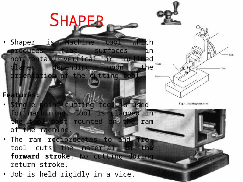
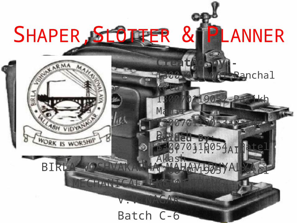
• Shaper is Machine tool which produces flat surfaces in horizontal, vertical or inclined planes depending upon the orientation of the cutting tool.
Features:• Single point cutting tool is used for
machining. Tool is clamped in the tool post mounted on the ram of the machine.
• The ram reciprocates to and fro, tool cuts the material in the forward stroke, No cutting during return stroke.
• Job is held rigidly in a vice.
SHAPER

APPLICATION DONE USING A SHAPER• Machining Horizontal Surfaces
• Machining Vertical Surfaces
• Machining Angular Surfaces
• Cutting Slots, Grooves & Key ways
• Machining irregular surfaces
• Machining Splines / Cutting Gears
4
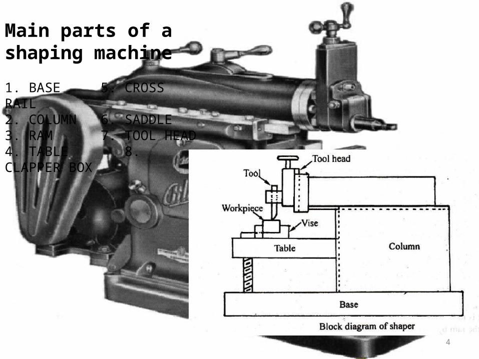
Main parts of a shaping machine
1. BASE 5. CROSS RAIL2. COLUMN 6. SADDLE3. RAM 7. TOOL HEAD4. TABLE 8. CLAPPER BOX
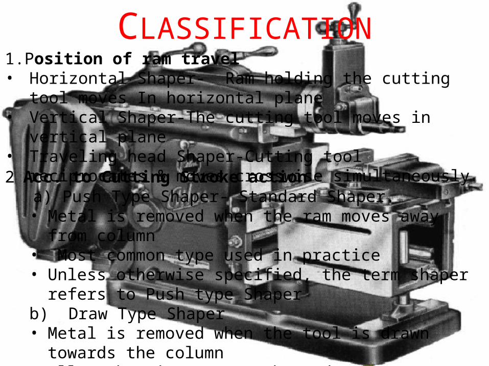
1.Position of ram travel • Horizontal Shaper- Ram holding the cutting tool moves In horizontal
plane• Vertical Shaper-The cutting tool moves in vertical plane• Traveling head Shaper-Cutting tool reciprocates & moves crosswise
simultaneously2 Acc. to Cutting Stroke action
a) Push Type Shaper- Standard Shaper. • Metal is removed when the ram moves away from column• Most common type used in practice• Unless otherwise specified, the term shaper refers to Push type
Shaper b) Draw Type Shaper• Metal is removed when the tool is drawn towards the column• Allows heavier cuts to be made• Less vibration during cutting
CLASSIFICATION
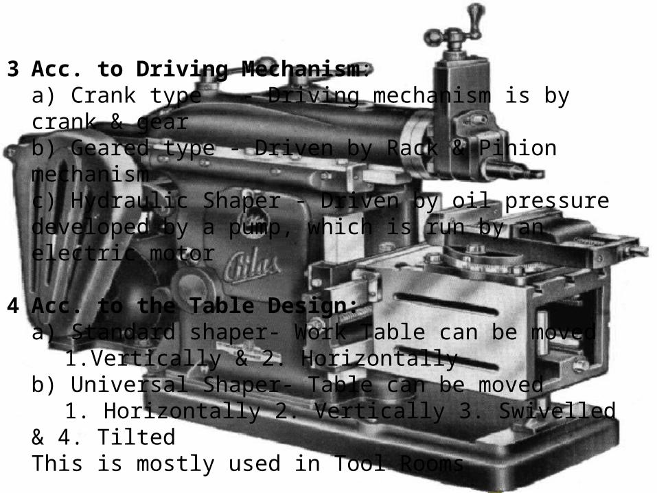
3 Acc. to Driving Mechanism: a) Crank type - Driving mechanism is by crank & gearb) Geared type - Driven by Rack & Pinion mechanism c) Hydraulic Shaper - Driven by oil pressure developed by a pump, which is run by an electric motor
4 Acc. to the Table Design:a) Standard shaper- Work Table can be moved
1.Vertically & 2. Horizontallyb) Universal Shaper- Table can be moved
1. Horizontally 2. Vertically 3. Swivelled & 4. TiltedThis is mostly used in Tool Rooms
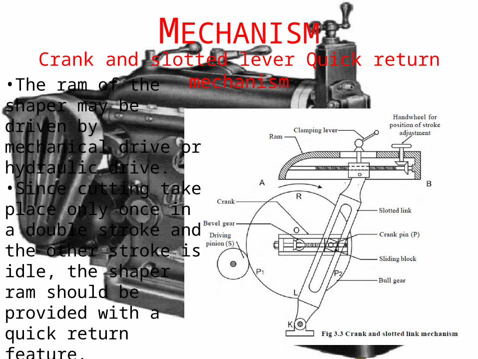
MECHANISM•The ram of the shaper may be driven by mechanical drive or hydraulic drive.•Since cutting take place only once in a double stroke and the other stroke is idle, the shaper ram should be provided with a quick return feature.•Mechanically driven shaper make use of the slotted arm quick return mechanism.
Crank and slotted lever Quick return mechanism
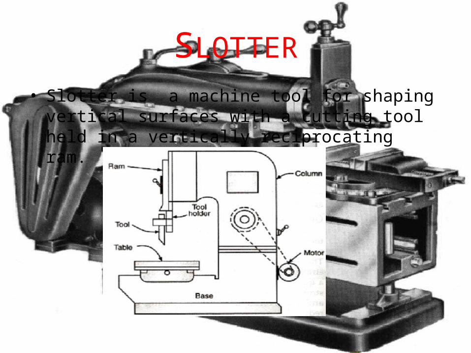
SLOTTER• Slotter is a machine tool for shaping vertical surfaces
with a cutting tool held in a vertically reciprocating ram.
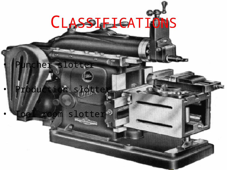
CLASSIFICATIONS
• Puncher slotter
• Production slotter
• Tool room slotter
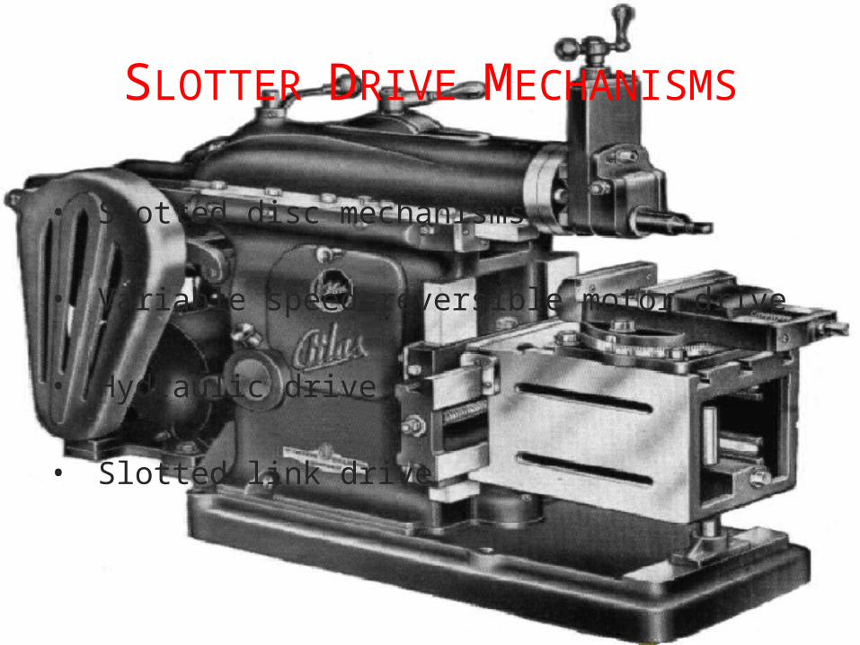
SLOTTER DRIVE MECHANISMS
• Slotted disc mechanisms
• Variable speed reversible motor drive
• Hydraulic drive
• Slotted link drive
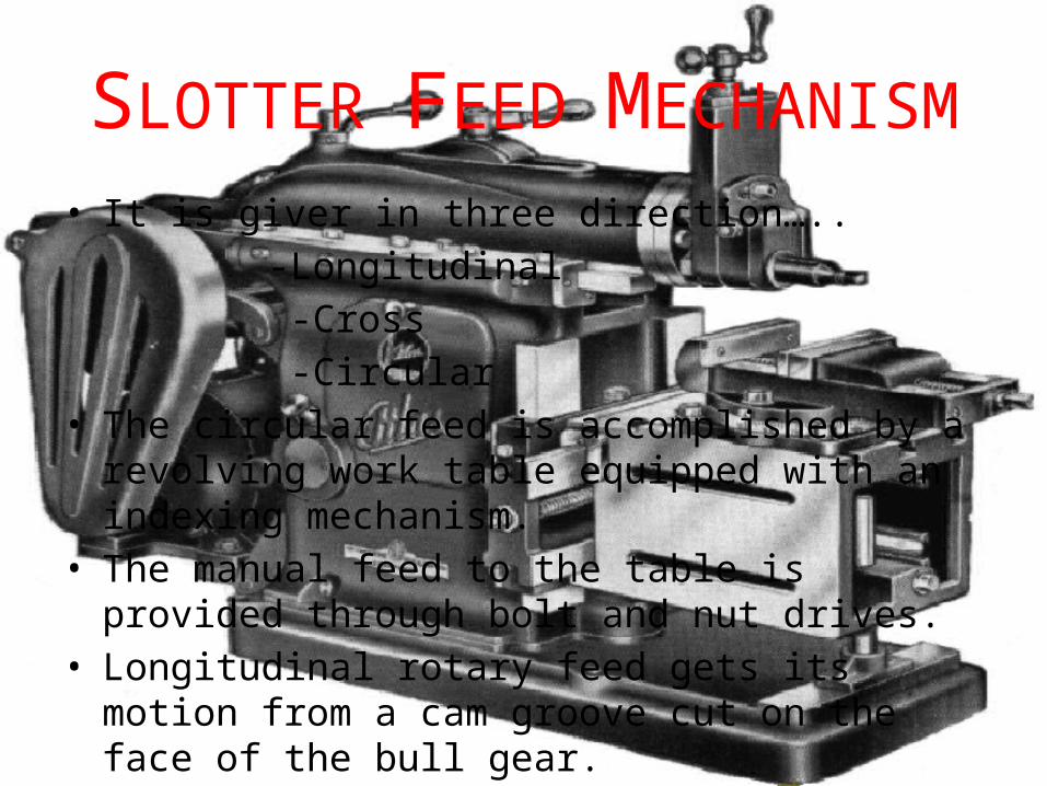
SLOTTER FEED MECHANISM• It is giver in three direction….. -Longitudinal -Cross -Circular• The circular feed is accomplished by a revolving work
table equipped with an indexing mechanism.• The manual feed to the table is provided through bolt
and nut drives.• Longitudinal rotary feed gets its motion from a cam
groove cut on the face of the bull gear.
APPLICATIONS OF SLOTTER• The following applications can be performed on the
slotter
• Cutting of internal grooves or key ways
• Cutting of internal gears
• Cutting of recesses
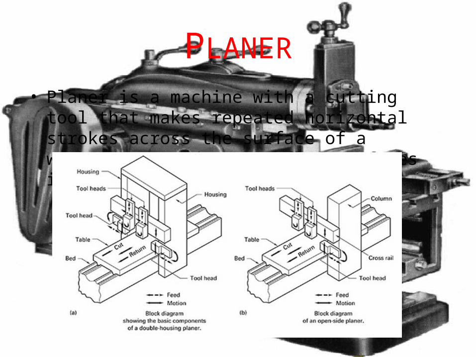
PLANER• Planer is a machine with a cutting tool that makes
repeated horizontal strokes across the surface of a workpiece: used to cut flat surfaces into metal
CLASSIFICATION OF PLANER
Planers are generalley divided into 5 types:
• Double Housing Planer• Open Side Planer• Edge Type Planer• Divide Table Planer• Pit Type Planer
DOUBLE HOUSING PLANER• It is the most common type of planer. It consists of mainly a
massive bed on which the worktable reciprocates, and two vertical columns or housing, one on each side of the bed. Each column carries a tool head that can be slide up and down on the column.
• A cross rail fitted between the two columns may carry one or two tool heads that can slide horizontally on the cross rail. All the tool heads can be clamped in position, and can be used collectively or individually depending on the requirements.
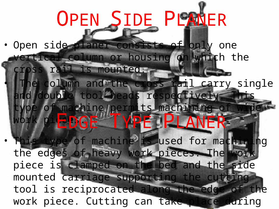
OPEN SIDE PLANER• Open side planer consists of only one vertical column or
housing on which the cross rail is mounted.• The column and the cross rail carry single and double tool
heads respectively. This type of machine permits machining of wide work pieces.
EDGE TYPE PLANER• This type of machine is used for machining the edges of heavy
work pieces. The work piece is clamped on the bed and the side mounted carriage supporting the cutting tool is reciprocated along the edge of the work piece. Cutting can take place during both directions of carriage travel.
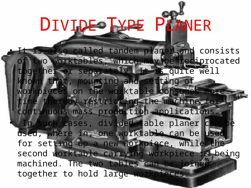
DIVIDE TYPE PLANER• It is also called tandem planer and consists of two
worktables, which may be reciprocated together or separately. It is quite well known that, mounting and setting of workpieces on the worktable consumes more time thereby restricting the machine for continuous mass production applications.
• In such cases, divided table planer can be used, where in, one worktable can be used for setting up a new workpiece, while the second worktable carrying workpiece is being machined. The two tables can be joined together to hold large workpieces.
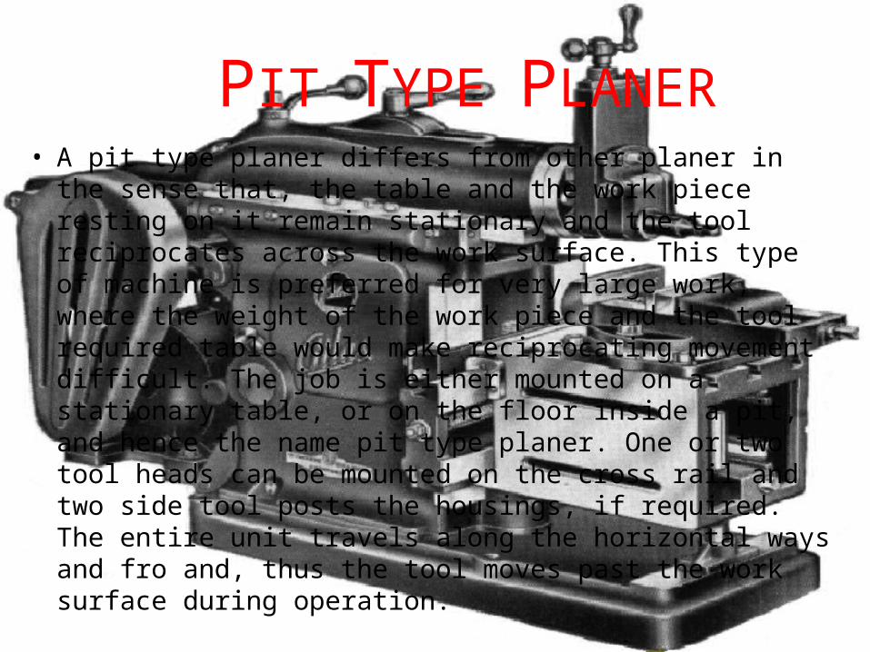
PIT TYPE PLANER• A pit type planer differs from other planer in the sense that,
the table and the work piece resting on it remain stationary and the tool reciprocates across the work surface. This type of machine is preferred for very large work, where the weight of the work piece and the tool required table would make reciprocating movement difficult. The job is either mounted on a stationary table, or on the floor inside a pit, and hence the name pit type planer. One or two tool heads can be mounted on the cross rail and two side tool posts the housings, if required. The entire unit travels along the horizontal ways and fro and, thus the tool moves past the work surface during operation.
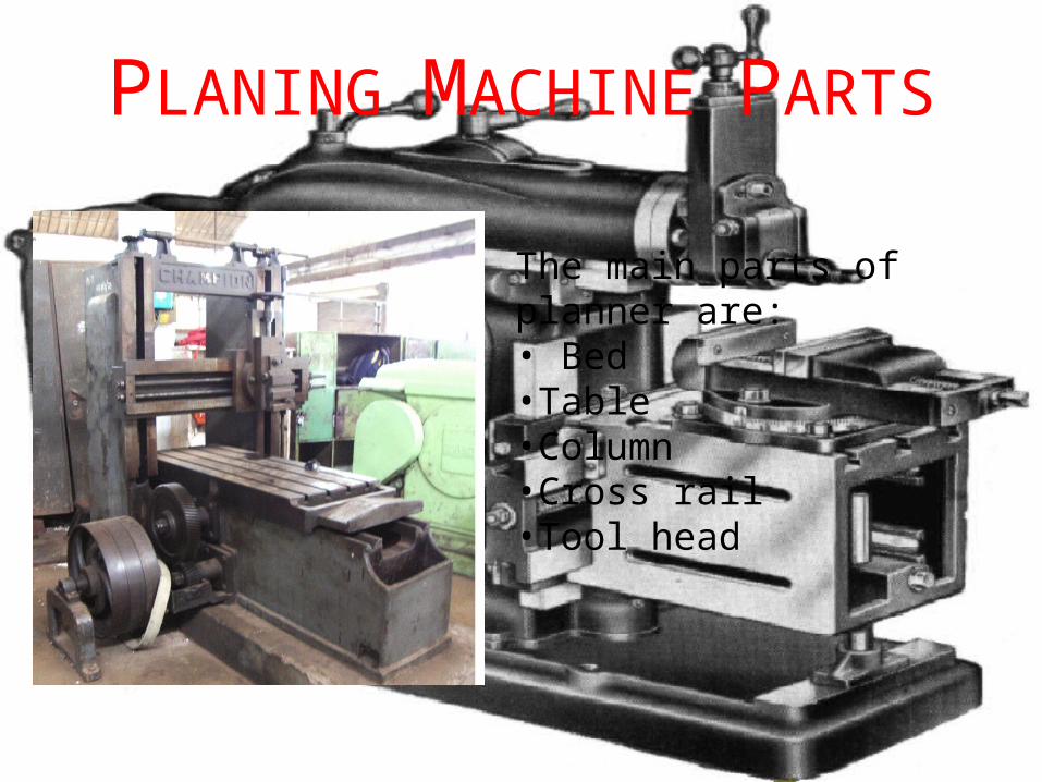
PLANING MACHINE PARTS
The main parts of planner are:• Bed•Table•Column•Cross rail•Tool head
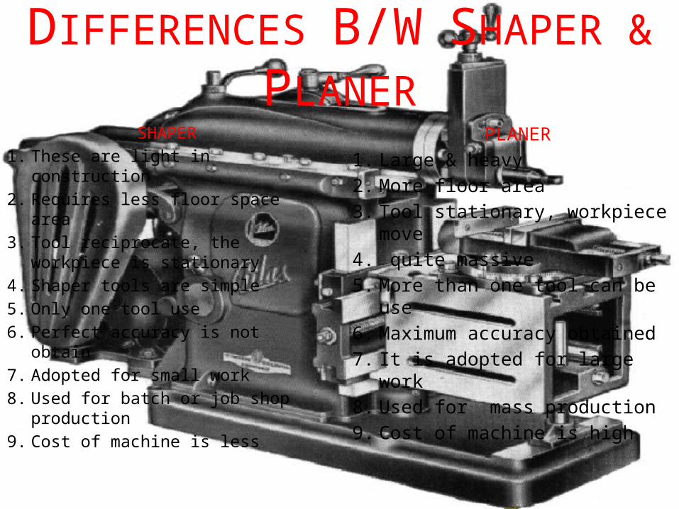
DIFFERENCES B/W SHAPER & PLANER
SHAPER1. These are light in construction2. Requires less floor space area3. Tool reciprocate, the workpiece is
stationary4. Shaper tools are simple5. Only one tool use6. Perfect accuracy is not obtain7. Adopted for small work8. Used for batch or job shop
production9. Cost of machine is less
PLANER1. Large & heavy2. More floor area3. Tool stationary, workpiece
move4. quite massive5. More than one tool can be use6. Maximum accuracy obtained7. It is adopted for large work8. Used for mass production9. Cost of machine is high
THANK YOU