
Shaft Clamping Elements - feyc.eu · PDF filePrecision transmission of torque with no backlash...
28
Shaft Clamping Elements BACK NEXT
Transcript of Shaft Clamping Elements - feyc.eu · PDF filePrecision transmission of torque with no backlash...

Shaft Clamping Elements 8
33904 Cross & Morse Shaft Clamping Cover:33904 Cross & Morse Shaft Clamping Cover 12/5/11 10:01 Page 1
BACK NEXT

The Company
T.D. Cross Ltd., reserve the right to change without notification dimensional and/or product specification shown in this catalogue, and to add or delete any product fromthe range in the interests of product development.All products shown in this catalogue are offered subject to the standard “Terms and Conditions of Sale”, copies on request. T.D. Cross Ltd., reserve copyright of thiscatalogue. No part thereof may be reproduced without prior permission.
Cross & Morse was established in 1984 through the amalgamation of two long standing and well respectedcompanies in the Power Transmission Industry, T.D. Cross and Morse Chain.
T.D. Cross & Sons was founded in 1870 in Birmingham, concentrating in the production of bicycle components underthe direction of the Cross family. They moved to the current factory site in 1950 and developed into production of apopular range of roller chain sprockets and gearing. The competitive pricing and quality of product soon establishedthe Company as a major supplier to both Agricultural and Industrial markets.
The Morse Chain Company was founded in 1894 also for the manufacture of bicycles in Pennsylvania, U.S.A. Thecompany moved into production of inverted tooth chain drives and established a manufacturing plant in London in1907, moving to the new Garden City of Letchworth, Herts. in 1918. The product range in the U.K. was developed toinclude Roller Chain and Sprockets, Couplings, Torque Limiters, Sprag Clutches and Timing Belt Drives, whilst in theU.S.A. by acquisition Morse also included the Denver Gearbox Range and the Sealmaster Bearing Products.
In 1987 Cross & Morse closed the Letchworth plant and centralised all production at the 10,000 sq. metre factory inGreat Barr, Birmingham where current production of Roller Chains, Sprockets, Gears, Timing Belt Pulleys, TorqueLimiters, Sprag Clutches and other specialised power transmission equipment is undertaken. In addition tomanufactured products, Cross & Morse are main agents for Morse-Emerson, U.S.A.; and Stieber Formsprag,Germany; providing an extensive range of power transmission products.
The company operates a policy of continued assessment to develop and improve its products and customer service.In pursuance of these objectives Cross & Morse has been successfully assessed by Lloyds, and is registered, as anapproved manufacturer of power transmission products to BS EN ISO 9001.
Roller Chain Drives Timing Belt Drives
Inverted Tooth Drives
Overload Clutches
Freewheel Clutches
Shaft Clamping Elements Sealmaster Bearings
Gears
Torque Limiters
Shaft CouplingsÆ
NEXT BACK

Cross Shaft Clamping Elements
1
Index
Contents Page
Cross Shaft Clamping Element Features 2Shaft Clamping Element Selection 3/4 Clamping Elements: Type RCK 15 - For Standard Hubs 5
Type RCK 13 - Standard General Purpose 6Type RCK 16 - Standard General Purpose 7Type RCK 70 - High Torque Units 8Type RCK 71 - High Torque Units 9Type RCK 80 - Minimal Axial Space 10Type ACE 81 - Small Axial Space/Bore Selection 11 Type RCK 40 - Original Compact Units 12/13Type RCK 10 to 12 - Maximum Torque Units 14/15Type RCK 45 - Very Compact Versatile Units 16Type RCK 61 - Compact Small Shaft Units 17Type RCK 50 - Clamping Rings 18Types CCE 54/55 - Single Nut Clamping Units 19Types RCK 19/20 - External Clamping Discs 20/21Type RCK 25 - External Clamping Units 22Type RCK 95 - Shaft Connecting Units 23
Installation and Assembly Instructions 24Formula and Conversion Factors 25
Te
l: +4
4 1
21
36
0 0
15
5 F
ax
: +4
4 1
21
32
5 1
07
9 E
ma
il: sa
les
@c
ros
sm
ors
e.c
om
NEXT BACK

2
Shaft Clamping Elements
Cross Shaft Clamping Elements provide the latest technologyin drive connection.
Cross Shaft Clamping Elements, by means of frictional forces, provide connection of all types of transmissionequipment to their respective shafts, enabling transmission of both torque and axial thrust loads. Precision taperedthrust cones within the clamping elements create high pressure between shaft and hub to securely fasten pulleys,sprockets, gears etc. Stresses in both hub and shaft are similar to heavy press fits, however, the actual stresses areeasy to calculate; and the hub can always be easily dismantled without damage to it or the shaft; only a torquewrench being required for both assembly and disassembly.Precision transmission of torque with no backlash is obtained with shaft clamping elements, without the need oftight manufacturing tolerances of mating components. Simplified designs can enable manufacturing cost reductions,coupled with easy assembly and disassembly.
Cross Shaft Clamping Elements provide an alternative method of connecting hubs to shafts to:-Tapered BushesHydraulic Clamping SystemsFine-bored Hubs, with Precision keyways and Locking SetscrewsHeavy Press FitsWelded Components
Cross Shaft Clamping Elements offer many advantages:-Easy Assembly - Hub to shaft connection is simple, only a torque wrench being required for
correct assembly.
Easy Disassembly - Just release of locking screws is all that is required on some series, others require simple positive release by tightening screws in jacking holes.
Simplified Manufacture - Parallel boring of hubs with H8 tolerance, or up to H11 on some sizes.
Lower Cost Assemblies - Eliminates costly machining of splines, keyways, and setscrews.
Long Fatigue Life - Elimination of keys prevents failure due to fretting, or notch initiatedcracking under torsional loads.
No Axial Location Required - Hubs can be positioned anywhere on shaft and locked to withstand high axial loads.
High Torque Transmission - Most series will transmit torques equivalent to shaft capacities, and forhigher torques clamping elements can be combined within one shaft/hub connection.
Small Shaft Diameters - Elimination of keyways often enables smaller diameter shafts to be used on many applications.
Freedom from Wear - Lack of moving parts means no wear. Shaft Clamping Elements can betightened and released as often as required with no wear.
Less Maintenance - Correctly assembled, Shaft Clamping Elements require no maintenance. Self locking action of most designs ensures torque transmission even if locking screws should vibrate loose during use.
True Running - Equally distributed friction locking ensures no play and high concentricity.
Shafts Remain Unmarked - Shaft Clamping Elements do not mark shafting ensuring ability of easydisassembly and assembly of components.
Timing of Drives - Infinitely variable angular positioning with simple clamping and release enables simple timing of drives.
Overload Protection - If design load is exceeded the clamping elements will slip on shaft providingprotection to other machine components.
Resistance to Contamination - When fully clamped contact surfaces are tightly pressed together preventingingress of dirt and moisture.
Sealed Joints - Clamping Elements Series RCK 50 can be used to provide fully Gastight Joints, to seal against passage of liquids or gases.
Te
l: +
44
12
1 3
60
01
55
F
ax
: +
44
12
1 3
25
10
79
E
ma
il:
sa
les
@c
ros
sm
ors
e.c
om
INDEX BACK NEXT

Te
l: +4
4 1
21
36
0 0
15
5 F
ax
: +4
4 1
21
32
5 1
07
9 E
ma
il: sa
les
@c
ros
sm
ors
e.c
om
Cross Shaft Clamping Elements
3
In order to make the best selection of a Cross Shaft Clamping Element for your application a number of factors mustbe taken into consideration. These include the shaft diameter; the outside diameter of the hub of connectingcomponent; the drive torque to be transmitted, and axial thrust loads, and tilting or bending loads, maximum shaftspeeds, operating temperature, and general design parameters and space restrictions.
Shaft Diameter:-The shaft diameter will determine the particular size of clamping element in any series, and by reference to thecatalogue details the suitability of that to meet the other parameters can be checked. Also hollow shafts must bechecked for any load carrying strength, see below.
Hub Outside Diameter:-The Hub Diameter has to be sufficient to support the stresses imposed by the shaft clamping element. The cataloguegives maximum hub diameters for medium carbon steel, but for other materials and method of determining refer below.Generally if hub diameter is over 2.5 times shaft diameter all series are suitable, but for smaller ratios consider types RCK 80, ACE 81, CCE 54 and CCE 55, and for very thin walled hubs use types RCK 19, RCK 20 and RCK 25.
Determination of Minimum Hub Diameter andMax. Hollow Shaft Bore:-The following calculations are for static conditions only, consideringonly stresses imposed by the clamping element. The hub diameter iscontrolled by the pressure applied by the outer cone of the clampingelement; the shape of the hub bore and total length of hub; and yieldstress for permanent elongation of 0.2%.
Minimum Hub Dia. Dm = D � + PhC� – PhC
Where D = Clamping element outside diameter mm� = Yield strength of material N/mm2
Ph = Surface pressure on hub N/mm2
C = Constant for Hub shape - see drawings
The tables in the catalogue give minimum hub diameters for hubsmanufactured in medium carbon steel (080M40 or C45) or other materialwhere � = 320 N/mm2. Values for � on other commonly used hubmaterials are:-
220 Grade Cast Iron � = 150 N/mm2
260 Grade Cast Iron � = 180 N/mm2
Mild Steels � = 220 N/mm2
070M55 (En9) � = 350 N/mm2
Stainless Steel � = 200 N/mm2
Aluminium � = 100 N/mm2
For hollow bored Shafting:-
Max. Bore in Shaft Dm = d � – 1.6 Ps�
Where d = Clamping element bore mmPs = Surface pressure on Shaft N/mm2
For solid shafting yield strength of material � must be higher than surface pressure Ps.
Maximum Shaft Speed:-The centrifugal forces generated by high shaft speeds can reduce torque capacity and increase stress loads on hubs.Consult Cross & Morse if speed of shaft results in outer clamping diameter D running above 25M/sec.
Operating Temperature:-Maximum temperatures should not exceed 100˚C. At temperatures above 70˚C the locking screws should berechecked after 1 hour operation, whilst assembly is still warm.
Hub Assembly Type AC=1.0
Hub Assembly Type BC=0.8
Hub Assembly Type CC=0.6
L1 � Hw � 2L1 L2 � Hw � 2L2
Where Hw = Hub WidthFor Dimensions L1 & L2 ref. Product Pages
Hw � 2L1 Hw � 2L2
Hw � 2L1 (All Types)
INDEX BACK NEXT

General Design Factors:-Never place a shaft clamping element radically inline with a bearing, as expansion due to clamping could causebearing seizure. To help final selection refer to table below for series selection.
Catalogue Page
RCK
10 to
12
RCK
13
RCK
15
RCK
16
RCK
19/2
0
RCK
25
RCK
40
RCK
45
RCK
50
CCE
54
CCE
55
RCK
61
RCK
70
RCK
71
RCK
80
RCK
81
RCK
95SERIES
Type of Load
Smooth Light Shock Medium Shock Heavy Shock
4
Shaft Clamping Selection
Drive Torque to be transmitted and Axial Thrust Loads:-The maximum effective torque Te derived from maximum Drive Torque Tm and maximum Axial Thrust Ft mustalways be less than the Torque Capacity M shown in tables for selected shaft clamping element.The maximum Drive Torque Tm must take into consideration any shock loads, and also the maximum starting torqueof drive. If the max. torque is not known, it can be estimated by applying the service factor from the table below tothe nominal drive torque Td, which can be derived from motor power P and shaft speed N r.p.m.
Drive Torque Td = 9550 P Nm Where P = Power kWN N = Shaft Speed rpm
Max. Drive Torque Tm = SF x Td Nm
Axial Thrust loads on shaft clamping elements reduces torque capacity. To determine a clamping elements capabilityto transmit both maximum torque and axial thrust loads the effective torque must be established if any axial loadingexists.
Maximum effective torque Te = Tm2
+ Nm
For correct selectionTorque Capacity M > Te (or Tm): and Axial Force Capacity F > Ft
Tilting or Bending Loads:-Always endeavour to design location of shaft clamping element directly beneath line of driving force on hub, iechain, vee belt etc. If overhang of load or force occurs the torque capacity of the clamping element can be reduced.Under no circumstances should the resultant couple force on the clamping element exceed 0.25M
Selection Factors SF
General Features of Cross Shaft Clamping Elements
Type of Motive Power
a.c. Motor direct start
d.c. Motor/a.c. Motor Invertor Control or Soft Start
Hydraulic or pneumatic motors
Internal combustion engines
3
1.5
1.2
3
3
2
1.5
3.5
3
2.5
2.5
4
4
3
3
5
FEATURE
1)Depends on design.
Ft.d2000
Ft = Max. Axial Load Nd = Shaft Diameter mm( )
2
Torque Capacity
Self Centring
Concentricity Accuracy
Axial Movement in Clamping
Hub Surface Pressures
Self Locking When Clamped
Suitable for Thin Walled Hub
Short Overall Length
Clamps Outside Hub Dia.
Cost of Assembly
Te
l: +
44
12
1 3
60
01
55
F
ax
: +
44
12
1 3
25
10
79
E
ma
il:
sa
les
@c
ros
sm
ors
e.c
om
HIGH MED MED MED HIGH HIGH MED MED LOW LOW MED LOW MED MED MED MED LOW
YES YES YES YES YES YES NO YES YES YES YES YES YES YES YES YES N/A
GOOD GOOD GOOD GOOD HIGH HIGH LOW GOOD LOW MED MED GOOD HIGH GOOD GOOD GOOD MED
NO YES NO NO NO NO NO YES NO1 NO1 NO1 YES YES NO NO NO NO
MED HIGH MED MED N/A N/A MED MED LOW LOW LOW LOW HIGH MED LOW LOW N/A
YES YES YES YES NO YES NO NO NO YES YES YES YES YES YES YES NO
NO NO NO NO YES YES NO NO YES YES YES NO NO NO YES YES N/A
NO YES YES YES YES YES YES YES YES YES YES YES NO NO NO NO NO
NO NO NO NO YES YES NO NO NO NO NO NO NO NO NO NO YES
HIGH MED LOW MED HIGH HIGH LOW LOW LOW LOW LOW LOW MED MED MED MED HIGH
14/15 6 5 7 20/21 22 12/13 16 18 19 19 17 8 9 10 11 23
INDEX BACK NEXT

Clamping Elements Type RCK 15
5
Designed for use with standardised ranges of pulleys, sprockets, and gears, theshaft clamping elements can accommodate a large range of shaft diameters witha hub of constant bore diameter. On clamping precise axial and radial position-ing is provided, combined with medium torque transmission capability.
Recommended tolerances for fulltorque transmission are:-
Shaft h8Hub H8
Clamping surfaces to be finished toRz ≤ 15 µm.
Cross & Morse can provide standardRoller Chain Sprockets finish bored toaccommodate RCK 15 shaft clampingelements, with ability to fit to eitherhub or sprocket end.
X = Distance required to removescrews, additional clearance for alankey may be required.Dimensions
Part No.
RCK15-14x55RCK15-16x55RCK15-18x55
RCK15-19x55RCK15-20x55RCK15-22x55
RCK15-24x55RCK15-25x55RCK15-28x55
RCK15-30x55RCK15-24x65RCK15-25x65
RCK15-28x65RCK15-30x65RCK15-32x65
RCK15-35x65RCK15-38x65RCK15-40x65
RCK15-30x80RCK15-32x80RCK15-35x80
RCK15-38x80RCK15-40x80RCK15-42x80
RCK15-45x80RCK15-48x80RCK15-50x80
RCK15-40x80HRCK15-45x80HRCK15-50x80H
141618
192022
242528
302425
283032
353840
303235
384042
454850
404550
555555
555555
555555
556565
656565
656565
808080
808080
808080
808080
393939
393939
393939
393939
393939
393939
414141
414141
414141
414141
171717
171717
171717
171717
171717
171717
202020
202020
202020
202020
222222
222222
222222
222222
222222
222222
252525
252525
252525
252525
313131
313131
313131
313131
313131
313131
333333
333333
333333
333333
252525
252525
252525
252525
252525
252525
252525
252525
252525
252525
282313353
372392431
470490549
588617637
725764823
902970
1029
108211551260
137014401510
162017351806
215724222700
393939
393939
393939
395151
515151
515151
727272
727272
727272
108108108
458400356
337320290
265255228
213332320
285267250
228210200
315298272
250238226
212198190
340302272
118118118
118118118
118118118
118122122
122122122
122122122
120120120
120120120
120120120
169169169
M8M8M8
M8M8M8
M8M8M8
M8M8M8
M8M8M8
M8M8M8
M8M8M8
M8M8M8
M8M8M8
M8M8M8
414141
414141
414141
414141
414141
414141
414141
414141
414141
414141
0.510.490.48
0.470.470.45
0.440.430.41
0.400.680.63
0.610.580.56
0.530.500.47
1.041.030.98
0.940.910.89
0.830.790.74
0.890.850.78
818181
818181
818181
819797
979797
979797
119119119
119119119
119119119
144144144
757575
757575
757575
758989
898989
898989
109109109
109109109
109109109
126126126
696969
696969
696969
698282
828282
828282
101101101
101101101
101101101
111111111
Dimensions mm
d D L L1 L2 L3 X
TorqueCap.
MNm
AxialForce
FkN
Approx.Weight
kg
ShaftPs
N/mm2
HubPh
N/mm2Assy
Type AAssy
Type BAssy
Type C
Size Torque
Nm
Surface Pressure Clamping Screws Min. Hub Dia* mm
*Minimum outside diameter of hubs manufactured in medium carbon steels with yield strength ≥ 320 N/mm2.
For hub types, and other materials, refer to page 3.For assembly and disassembly instructions refer to page 24.
Te
l: +4
4 1
21
36
0 0
15
5 F
ax
: +4
4 1
21
32
5 1
07
9 E
ma
il: sa
les
@c
ros
sm
ors
e.c
om
INDEX BACK NEXT

Te
l: +
44
12
1 3
60
01
55
F
ax
: +
44
12
1 3
25
10
79
E
ma
il:
sa
les
@c
ros
sm
ors
e.c
om
Dimensions
6
Clamping Elements Type RCK 13
These shaft clamping elements are very compact units capable oftransmitting medium torques. Their design ensures good concentricitybetween hubs and shafts, without any other means of location. A slightaxial movement between hub and shaft occurs during clamping. Theseunits can be installed totally within the hub providing optimum safety, andminimal axial length.
Part No.
RCK13-18x47RCK13-19x47RCK13-20x47RCK13-22x47
RCK13-24x50RCK13-25x50RCK13-28x55RCK13-30x55
RCK13-32x60RCK13-35x60RCK13-38x65RCK13-40x65
RCK13-45x75RCK13-50x80RCK13-55x85RCK13-60x90
RCK13-65x95RCK13-70x110RCK13-75x115RCK13-80x120
RCK13-85x125RCK13-90x130RCK13-95x135RCK13-100x145
RCK13-110x155RCK13-120x165RCK13-130x180RCK13-140x190
RCK13-150x200RCK13-160x210RCK13-170x225RCK13-180x235
RCK13-190x250RCK13-200x260RCK13-220x285RCK13-240x305RCK13-260x325RCK13-280x355RCK13-300x375
18192022
24252830
32353840
45505560
65707580
859095
100
110120130140
150160170180
190200220240260280300
47474747
50505555
60606565
75808590
95110115120
125130135145
155165180190
200210225235
250260285305325355375
34343434
34343434
34343434
41414141
41505050
50505056
56566468
68687878
7878888888102102
17171717
17171717
17171717
20202020
20242424
24242426
26263434
34344444
44445151516060
22222222
22222222
22222222
25252525
25303030
30303032
32324040
40404949
49495757576666
28282828
28282828
28282828
33333333
33404040
40404044
44445254
54546464
64647272728484
20202020
20202020
20202020
25252525
25303030
30303035
35353540
40405050
50505555556565
350355360400
440560625650
950105011401200
2180243030503350
4080628066807130
84509080
1058013380
14580178802595026950
32950388004130043700
577006070078100106500138500160300193200
39373636
37454543
59606060
9797
111112
126179178178
199202223268
265298399385
439485486486
607607710848101710941230
280280280268
243280250235
290268252232
285258268243
253278258248
258248258268
238248238208
228213188178
173165180182198169174
120120120123
120138128128
150150146146
168158173163
173178168168
178168178188
178178168148
168170130125
145140132154174143152
M6M6M6M6
M6M6M6M6
M6M6M6M6
M8M8M8M8
M8M10M10M10
M10M10M10M12
M12M12M12M14
M14M14M14M14
M14M14M16M16M16M18M18
14141414
14141414
14141414
35353535
35707070
707070
125
125125125190
190190190190
190190290290290400400
0.270.270.260.25
0.280.270.320.30
0.370.340.410.38
0.630.680.730.78
0.831.331.391.48
1.551.631.702.60
2.803.004.604.90
5.205.507.708.10
8.609.0012.0013.0013.9020.4021.60
70707070
74798484
100100106106
134137156158
174206206215
234233253284
290309323313
358380346355
408416442515598574629
64646465
68727777
89899595
117121135139
151177180188
202203218241
250266282280
313331315325
365375402458518516559
59595959
63657070
80808686
104109119123
133156159166
177180191210
219233249253
277292289298
330340367411456467503
Dimensions mm
d D L L1 L2 L3 X
TorqueCap.
MNm
AxialForce
FkN
Approx.Weight
kg
ShaftPs
N/mm2
HubPh
N/mm2Assy
Type AAssy
Type BAssy
Type C
Size Torque
Nm
Surface Pressure Clamping Screws Min. Hub Dia* mm
*Minimum outside diameter of hubs manufactured in medium carbon steels with yield strength ≥ 320 N/mm2.
For hub types, and other materials, refer to page 3.For assembly and disassembly instructions refer to page 24.
Recommended tolerances for fulltorque transmission are:-
Shaft h8Hub H8
Clamping surfaces to be finished toRz ≤ 15 µm.
X = Distance required to removescrews, additional clearance for alankey may be required.
INDEX BACK NEXT

Clamping Elements Type RCK 16
These clamping elements are basically to same design as RCK 13, but withincreased diameter flange to locate hub and prevent axial movements, socombining good concentricity with positive axial location. The increase infriction between the cones due to axial restriction results in torquereduction of approx 20%, but this also means reduced surface pressures toboth hub and shaft.
Dimensions
Part No.
RCK16-18x47RCK16-19x47RCK16-20x47RCK16-22x47
RCK16-24x50RCK16-25x50RCK16-28x55RCK16-30x55
RCK16-32x60RCK16-35x60RCK16-38x65RCK16-40x65
RCK16-45x75RCK16-50x80RCK16-55x85RCK16-60x90
RCK16-65x95RCK16-70x110RCK16-75x115RCK16-80x120
RCK16-85x125RCK16-90x130RCK16-95x135RCK16-100x145
RCK16-110x155RCK16-120x165RCK16-130x180RCK16-140x190
RCK16-150x200RCK16-160x210RCK16-170x225RCK16-180x235
RCK16-190x250RCK16-200x260RCK16-220x285RCK16-240x305RCK16-260x325RCK16-280x355RCK16-300x375
18192022
24252830
32353840
45505560
65707580
859095
100
110120130140
150160170180
190200220240260280300
47474747
50505555
60606565
75808590
95110115120
125130135145
155165180190
200210225235
250260285305325355375
34343434
34343434
34343434
41414141
41505050
50505056
56566468
68687878
7878888888102102
17171717
17171717
17171717
20202020
20242424
24242426
26263434
34344444
44445151516060
22222222
22222222
22222222
25252525
25303030
30303032
32324040
40404949
49495757576666
28282828
28282828
28282828
33333333
33404040
40404044
44445254
54546464
64647272728484
20202020
20202020
20202020
25252525
25303030
30303035
35353540
40405050
50505555556565
264274284314
401441490529
755824892941
1716189324032648
3188490551505490
662069608190
10100
11030136001900021800
25600313003320035000
46500490005710077800101200113300136500
29292829
33353535
47474747
76768788
98140137137
156155172202
201227292311
341391391389
489500519649778808910
215215215196
215210196186
210186191186
225205210186
196215195185
195185195205
190205186177
185174147139
132125132134145120123
93939393
107107
9898
112107112102
132127132122
132137127122
132127137145
135142137127
130150110100
12011097113127101107
M6M6M6M6
M6M6M6M6
M6M6M6M6
M8M8M8M8
M8M10M10M10
M10M10M10M12
M12M12M12M14
M14M14M14M14
M14M14M16M16M16M18M18
17171717
17171717
17171717
41414141
41838383
838383
145
145145145230
230230230230
230230360360360480480
0.280.270.260.25
0.280.270.350.32
0.380.350.410.39
0.650.690.750.80
0.851.351.421.51
1.581.661.732.64
2.843.054.704.95
5.305.607.908.30
8.809.2012.3013.3014.3021.0022.20
63636363
71717575
86859490
116122132134
147174175179
194198213236
243266284289
308349322325
371372390441495492531
60606060
66667171
80798784
106111120123
134157160164
176181193212
220239257264
280311298303
341345365408452460493
56565656
61616666
74748079
97102109114
122143147151
161166176192
201217234242
256280277284
314321343378414430460
Dimensions mm
d D L L1 L2 L3 X
TorqueCap.
MNm
AxialForce
FkN
Approx.Weight
kg
ShaftPs
N/mm2
HubPh
N/mm2Assy
Type AAssy
Type BAssy
Type C
Size Torque
Nm
Surface Pressure Clamping Screws Min. Hub Dia* mm
*Minimum outside diameter of hubs manufactured in medium carbon steels with yield strength ≥ 320 N/mm2.
For hub types, and other materials, refer to page 3.For assembly and disassembly instructions refer to page 24.
Recommended tolerances for fulltorque transmission are:-
Shaft h8Hub H8
Clamping surfaces to be finished toRz ≤ 15 µm.
X = Distance required to removescrews, additional clearance for alankey may be required.
Te
l: +4
4 1
21
36
0 0
15
5 F
ax
: +4
4 1
21
32
5 1
07
9 E
ma
il: sa
les
@c
ros
sm
ors
e.c
om
7
INDEX BACK NEXT

Te
l: +
44
12
1 3
60
01
55
F
ax
: +
44
12
1 3
25
10
79
E
ma
il:
sa
les
@c
ros
sm
ors
e.c
om
8
Clamping Elements Type RCK 70
These shaft clamping elements are designed to give optimum concentricity,both radically and axially. Similar in design to the RCK 13, but withincreased length to provide improved support, and reduced pressures onboth shaft and hub. These units must always be installed inside the hub toensure optimum concentricity. Axial movement of hub will occur duringclamping operation.
Dimensions
Part No.
RCK70-19x47RCK70-20x47RCK70-22x47RCK70-24x50
RCK70-25x50RCK70-28x55RCK70-30x55RCK70-32x60
RCK70-35x60RCK70-38x65RCK70-40x65RCK70-42x75
RCK70-45x75RCK70-48x80RCK70-50x80RCK70-55x85
RCK70-60x90RCK70-65x95RCK70-70x110RCK70-75x115
RCK70-80x120RCK70-85x125RCK70-90x130RCK70-95x135
RCK70-100x145RCK70-110x155RCK70-120x165RCK70-130x180
RCK70-140x190RCK70-150x200RCK70-160x210RCK70-170x225RCK70-180x235RCK70-190x250RCK70-200x260
19202224
25283032
35384042
4548 5055
60657075
80859095
100110120130
140150160170180190200
47474750
50555560
60656575
75808085
9095
110115
120125130135
145155165180
190200210225235250260
45454545
45454545
45454555
55555555
55556772
72727272
89898989
98989898989898
26262626
26262626
26262630
30303030
30304040
40404040
46464646
51515151515151
31313131
31313131
31313136
36363636
36364646
46464646
52525252
59595959595959
39393939
39393939
39393947
47474747
47475762
62626262
77777777
84848484848484
25252525
25252525
25252530
30303030
30303535
35353535
45454545
45454545454545
403443510607
689826865
1129
1177145115372314
2657277530113729
3949497081288694
9458111671197013950
18295201442634528135
36177434764946644452489016500068000
42444651
55595871
677677
110
118116120136
132153232232
236263266294
366366439433
517580618523543684680
228226215215
225215196225
196205196232
232213213218
194208220205
196205196205
211192211192
192201201160157192184
989893
102
102107117111
116121122137
137132132142
153137140135
127142135145
145136152137
142150150120117146141
M6M6M6M6
M6M6M6M6
M6M6M6M8
M8M8M8M8
M8M8M10M10
M10M10M10M10
M12M12M12M12
M14M14M14M14M14M14M14
17171717
17171717
17171741
41414141
41418383
83838383
145145145145
230230230230230230230
0.380.370.360.39
0.380.450.420.52
0.480.570.540.91
0.891.000.951.02
1.111.192.202.53
2.662.792.933.06
4.544.925.285.52
7.257.658.168.759.3510.8011.30
64646370
70788186
889797
119
119124124137
151150176180
183201204220
236244277284
306333349334345409417
60606065
65727480
818989
107
107113113123
135136159163
167181185197
212221246257
275297311307318367376
57575661
61676974
75828298
98103103112
121124144149
153164168178
192201221234
250267280283294331341
Dimensions mm
d D L L1 L2 L3 X
TorqueCap.
MNm
AxialForce
FkN
Approx.Weight
kg
ShaftPs
N/mm2
HubPh
N/mm2Assy
Type AAssy
Type BAssy
Type C
Size Torque
Nm
Surface Pressure Clamping Screws Min. Hub Dia* mm
*Minimum outside diameter of hubs manufactured in medium carbon steel with yield strength ≥ 320 N/mm2.
For hub types, and other materials, refer to page 3.For assembly and disassembly instructions refer to page 24.
Recommended tolerances for fulltorque transmission are:-
Shaft h8Hub H8
Clamping surfaces to be finished toRz ≤ 15 µm.
X = Distance required to removescrews, additional clearance for alankey may be required.
INDEX BACK NEXT

Clamping Elements Type RCK 71
9
The RCK 71 is a type RCK 70 with addition of a distance ring to preventaxial movement of the hub during clamping. Due to the additional frictionbetween the element and hub during clamping maximum torques arereduced, but with reduction in surface pressures also. This design can bemounted within the confines of a hub providing a stepped bore is providedto accommodate the flange.
Dimensions
Part No.
RCK71-19x47RCK71-20x47RCK71-22x47RCK71-24x50
RCK71-25x50RCK71-28x55RCK71-30x55RCK71-32x60
RCK71-35x60RCK71-38x65RCK71-40x65RCK71-42x75
RCK71-45x75RCK71-48x80RCK71-50x80RCK71-55x85
RCK71-60x90RCK71-65x95RCK71-70x110RCK71-75x115
RCK71-80x120RCK71-85x125RCK71-90x130RCK71-95x135
RCK71-100x145RCK71-110x155RCK71-120x165RCK71-130x180
RCK71-140x190RCK71-150x200RCK71-160x210RCK71-170x225RCK71-180x235RCK71-190x250RCK71-200x260
19202224
25283032
35384042
4548 5055
60657075
80859095
100110120130
140150160170180190200
47474750
50555560
60656575
75808085
9095
110115
120125130135
145155165180
190200210225235250260
45454545
45454545
45454555
55555555
55556772
72727272
89898989
98989898989898
26262626
26262626
26262630
30303030
30304040
40404040
46464646
51515151515151
31313131
31313131
31313136
36363636
36364646
46464646
52525252
59595959595959
39393939
39393939
39393947
47474747
47475762
62626262
77777777
84848484848484
25252525
25252525
25252530
30303030
30303535
35353535
45454545
45454545454545
294313362421
470578637784
843101011081892
1912213721672677
2853350057176207
670780028502
10002
13336145821908320417
24920301303252033350336004640048200
31313335
38414249
48535590
85898797
95108163166
168188189211
267265318314
356402407392373488482
228226206206
221202221197
202197234216
216221221221
197206221216
198216197187
197197216198
188198198158154150144
969697
100
110105118114
118121143135
135142143143
131142142148
139157143138
148178158143
138149149119119114110
M6M6M6M6
M6M6M6M6
M6M6M6M8
M8M8M8M8
M8M8M10M10
M10M10M10M10
M12M12M12M12
M14M14M14M14M14M14M14
17171717
17171717
17171741
41414141
41418383
83838383
145145145145
230230230230230230230
0.390.380.370.41
0.400.480.450.56
0.520.620.590.97
0.951.071.021.09
1.191.272.032.65
2.782.923.073.21
4.805.205.585.86
7.628.048.569.199.8311.3511.90
64646469
72778187
8897
105118
118129129137
139153177190
191214210214
239290283291
301331348333347363372
60606065
66727580
818994
107
107116116124
126138159170
172189189193
214250251262
272296311306319335345
56565660
62676975
75828697
97105105112
116125145153
157169171176
193219224237
248266280282295311321
Dimensions mm
d D L L1 L2 L3 X
TorqueCap.
MNm
AxialForce
FkN
Approx.Weight
kg
ShaftPs
N/mm2
HubPh
N/mm2Assy
Type AAssy
Type BAssy
Type C
Size Torque
Nm
Surface Pressure Clamping Screws Min. Hub Dia* mm
*Minimum outside diameter of hubs manufactured in medium carbon steels with yield strength ≥ 320 N/mm2.
For hub types, and other materials, refer to page 3.For assembly and disassembly instructions refer to page 24.
Recommended tolerances for fulltorque transmission are:-
Shaft h8Hub H8
Clamping surfaces to be finished toRz ≤ 15 µm.
X = Distance required to removescrews, additional clearance for alankey may be required.
Te
l: +4
4 1
21
36
0 0
15
5 F
ax
: +4
4 1
21
32
5 1
07
9 E
ma
il: sa
les
@c
ros
sm
ors
e.c
om
INDEX BACK NEXT

10
Clamping Elements Type RCK 80
Available for shaft diameters down to 6mm, these shaft clamping elementsare designed to fit into small diameter hubs, being particularly suited tolight duty, light torque applications. A spacer ring prevents axial movementduring clamping; and design ensures good levels of concentricity.For correct operation of these units, the hub diameter should not be lessthan the flange diameter D2, even though with many materials stress limitswould allow selection of smaller hub diameters.
For the unit to function correctly hub diameter should not be less than the flange outside diameter D2.*Minimum outside diameter of hubs manufactured in medium carbon steels with yield strength ≥ 320 N/mm
2.
For hub types, and other materials, refer to page 3. For assembly and disassembly instructions refer to page 24.
Dimensions
Part No.
RCK80-6x14 6 14 23 25 25.5 10 19 23 10 12 4 187 80 M3 2.2 0.04 18 18 17RCK80-8x15 8 15 24 28 28.0 12 21 24 12 28 7 197 105 M4 5 0.05 21 20 19RCK80-9x16 9 16 28 32 31.0 14 23 27 12 31 7 164 92 M4 5 0.07 22 21 19RCK80-10x16 10 16 28 32 31.0 14 23 27 12 40 8 144 90 M4 5 0.06 22 21 19RCK80-11x18 11 18 30 34 31.0 14 23 27 12 51 9 175 107 M4 5 0.09 26 24 22
RCK80-12x18 12 18 30 34 31.0 14 23 27 12 56 9 161 107 M4 5 0.08 26 24 22RCK80-14x23 14 23 35 39 31.0 14 23 27 12 64 9 138 84 M4 5 0.18 30 29 27RCK80-15x24 15 24 40 45 42.0 16 29 36 18 145 19 162 101 M6 17 0.22 34 31 29RCK80-16x24 16 24 40 45 42.0 16 29 36 18 155 19 152 101 M6 17 0.21 34 31 29RCK80-17x26 17 26 42 47 45.5 18 32 38 18 170 20 191 125 M6 17 0.21 40 36 33RCK80-18x26 18 26 42 47 44.0 18 31 38 18 158 18 160 111 M6 17 0.24 38 35 33
RCK80-19x27 19 27 43 48 44.0 18 31 38 18 199 21 152 107 M6 17 0.25 39 36 33RCK80-20x28 20 28 44 49 44.0 18 31 45 18 210 21 144 103 M6 17 0.26 39 37 34RCK80-22x32 22 32 48 54 51.0 25 38 45 18 232 21 113 78 M6 17 0.35 41 39 37RCK80-24x34 24 34 50 56 52.5 25 38 45 18 253 21 103 73 M6 17 0.36 43 41 39
RCK80-25x34 25 34 50 56 52.5 25 38 45 18 263 21 99 73 M6 17 0.40 43 41 39RCK80-28x39 28 39 55 61 52.5 25 38 45 18 428 31 111 80 M6 17 0.42 51 48 46RCK80-30x41 30 41 57 63 52.5 25 38 45 18 474 32 124 91 M6 17 0.44 55 52 49RCK80-32x43 32 43 59 65 56.0 30 43 50 18 600 38 97 72 M6 17 0.46 54 52 50
RCK80-35x47 35 47 63 69 56.0 30 43 50 18 737 42 118 88 M6 17 0.57 63 59 56RCK80-38x50 38 50 66 72 56.0 30 43 50 18 800 42 109 83 M6 17 0.60 66 62 59RCK80-40x53 40 53 69 75 58.0 32 45 52 18 947 47 109 82 M6 17 0.66 69 66 62RCK80-42x55 42 55 71 77 58.0 32 45 52 18 994 47 103 79 M6 17 0.71 71 68 64RCK80-45x59 45 59 79 85 72.0 40 56 64 22 1750 78 127 97 M8 41 1.14 81 76 71
RCK80-48x62 48 62 82 88 72.0 40 56 64 22 1867 78 119 92 M8 41 1.40 84 79 74RCK80-50x65 50 65 85 92 82.0 50 66 74 22 2431 97 127 98 M8 41 1.58 90 84 79RCK80-55x71 55 71 91 98 82.0 50 66 74 22 2674 97 105 81 M8 41 2.00 92 88 83RCK80-60x77 60 77 97 104 82.0 50 66 74 22 2917 97 95 74 M8 41 2.30 98 93 89
RCK80-65x84 65 84 104 111 82.0 50 66 74 22 3160 97 89 69 M8 41 2.50 105 100 96RCK80-70x90 70 90 115 122 101.0 60 80 91 25 4322 123 86 67 M10 83 2.83 112 107 103RCK80-75x95 75 95 119 126 101.0 60 80 91 25 6171 165 94 74 M10 83 3.10 121 115 110RCK80-80x100 80 100 124 131 106.0 65 85 96 25 7899 197 96 77 M10 83 3.27 128 122 116RCK80-85x106 85 106 130 137 106.0 65 85 96 25 8393 197 91 73 M10 83 3.50 134 128 122
RCK80-90x112 90 112 136 143 106.0 65 85 96 25 10367 230 63 51 M10 83 3.80 132 128 124RCK80-95x120 95 120 144 153 106.0 65 85 96 25 10943 230 95 75 M10 83 4.20 153 145 139RCK80-100x125 100 125 153 162 114.0 65 89 102 25 14520 290 114 91 M10 83 4.90 168 158 149RCK80-110x140 110 140 168 177 119.0 70 94 107 30 15972 290 95 75 M12 145 5.80 178 170 162RCK80-120x155 120 155 185 195 139.0 90 114 127 30 23231 387 92 71 M12 145 6.60 195 186 178
RCK80-130x165 130 165 195 205 139.0 90 114 127 30 25168 387 84 66 M12 145 7.30 204 195 187RCK80-140x175 140 175 205 215 139.0 90 114 127 30 27104 387 79 63 M12 145 7.90 214 206 197RCK80-150x185 150 185 215 225 139.0 90 114 127 30 29041 387 73 59 M12 145 8.70 223 215 207
Dimensions mm
d D L L1D1 L2D2 L3 X
TorqueCap.
MNm
AxialForce
FkN
ApproxWeight
kg
ShaftPs
N/mm2
HubPh
N/mm2Assy
Type AAssy
Type BAssy
Type C
Size Torque
Nm
Surface Pressure Clamping Screws Min. Hub Dia* mm
Recommended tolerances for fulltorque transmission are:-
Shaft h8Hub H8
Clamping surfaces to be finished toRz ≤ 15 µm.
X = Distance required to removescrews, additional clearance for alankey may be required.
Te
l: +
44
12
1 3
60
01
55
F
ax
: +
44
12
1 3
25
10
79
E
ma
il:
sa
les
@c
ros
sm
ors
e.c
om
INDEX BACK NEXT
ACE81-10x26ACE81-11x26ACE81-12x26ACE81-14x26ACE81-15x26ACE81-16x26ACE81-18x26ACE81-19x26ACE81-20x26ACE81-19x38ACE81-20x38ACE81-22x38ACE81-24x38ACE81-25x38ACE81-28x38ACE81-30x38ACE81-19x38HACE81-20x38HACE81-22x38HACE81-24x38HACE81-25x38HACE81-28x38HACE81-30x38HACE81-24x52ACE81-25x52ACE81-28x52ACE81-30x52ACE81-32x52ACE81-35x52ACE81-38x52ACE81-40x52ACE81-42x52ACE81-28x72ACE81-30x72ACE81-32x72ACE81-35x72ACE81-38x72ACE81-40x72ACE81-42x72ACE81-45x72ACE81-48x72ACE81-50x72ACE81-55x72ACE81-60x72
11
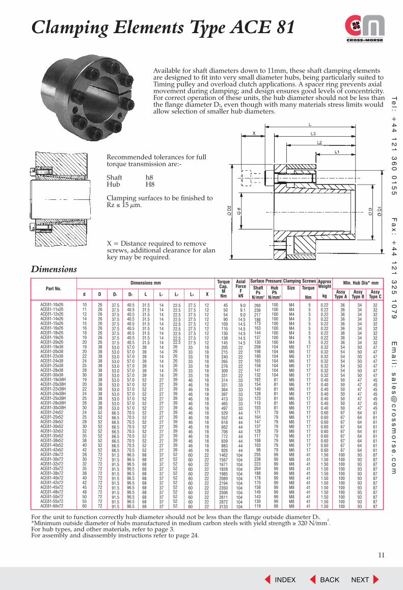
Clamping Elements Type ACE 81
Available for shaft diameters down to 11mm, these shaft clamping elementsare designed to fit into very small diameter hubs, being particularly suited toTiming pulley and overload clutch applications. A spacer ring prevents axialmovement during clamping; and design ensures good levels of concentricity.For correct operation of these units, the hub diameter should not be less thanthe flange diameter D2, even though with many materials stress limits wouldallow selection of smaller hub diameters.
Dimensions
Part No.Dimensions mm
d D L L1D1 L2D2 L3 X
TorqueCap.
MNm
AxialForce
FkN
ApproxWeight
kg
ShaftPs
N/mm2
HubPh
N/mm2
AssyType A
AssyType B
AssyType C
Size Torque
Nm
Surface Pressure Clamping Screws Min. Hub Dia* mm
For the unit to function correctly hub diameter should not be less than the flange outside diameter D2.*Minimum outside diameter of hubs manufactured in medium carbon steels with yield strength ≥ 320 N/mm
2.
For hub types, and other materials, refer to page 3. For assembly and disassembly instructions refer to page 24.
Recommended tolerances for fulltorque transmission are:-
Shaft h8Hub H8
Clamping surfaces to be finished toRz ≤ 15 µm.
X = Distance required to removescrews, additional clearance for alankey may be required.
1011121415161819201920222425283019202224252830242528303235384042283032353840424548505560
2626262626262626263838383838383838383838383838525252525252525252727272727272727272727272
40.540.540.540.540.540.540.540.540.557.057.057.057.057.057.057.057.057.057.057.057.057.057.070.570.570.570.570.570.570.570.570.596.596.596.596.596.596.596.596.596.596.596.596.5
31.531.531.531.531.531.531.531.531.53939393939393952525252525252525252525252525252686868686868686868686868
1414141414141414141414141414141427272727272727272727272727272727373737373737373737373737
27.527.527.527.527.527.527.527.527.53333333333333346464646464646464646464646464646606060606060606060606060
1212121212121212121818181818181818181818181818181818181818181818222222222222222222222222
45505490
109116130138145205215240265276309331314331364397413465497529552618662706772839883926
146215671671182819852089219423502506261128723133
9.09.19.0
14.514.514.514.514.514.52222222222222233333333333333444444444444444444
104104104104104104104104104104104104
260236217186173163144137130208198180165158141132162154140128123110103171164147137128117108103
98255238223204188178170158149143130119
100100100100100100100100100104104104104104104104
81818181818181797979797979797979999999999999999999999999
M4M4M4M4M4M4M4M4M4M6M6M6M6M6M6M6M6M6M6M6M6M6M6M6M6M6M6M6M6M6M6M6M8M8M8M8M8M8M8M8M8M8M8M8
555555555
1717171717171717171717171717171717171717171717414141414141414141414141
0.220.220.220.220.220.220.220.220.220.320.320.320.320.320.320.320.400.400.400.400.400.400.400.600.600.600.600.600.600.600.600.601.501.501.501.501.501.501.501.501.501.501.501.50
3636363636363636365454545454545450505050505050676767676767676767
100100100100100100100100100100100100
3434343434343434345050505050505047474747474747646464646464646464939393939393939393939393
3232323232323232324747474747474745454545454545616161616161616161878787878787878787878787
37.537.537.537.537.537.537.537.537.553.053.053.053.053.053.053.053.053.053.053.053.053.053.066.566.566.566.566.566.566.566.566.591.591.591.591.591.591.591.591.591.591.591.591.5
22.522.522.522.522.522.522.522.522.52626262626262639393939393939393939393939393939525252525252525252525252
Te
l: +4
4 1
21
36
0 0
15
5 F
ax
: +4
4 1
21
32
5 1
07
9 E
ma
il: sa
les
@c
ros
sm
ors
e.c
om
INDEX BACK NEXT

Te
l: +
44
12
1 3
60
01
55
F
ax
: +
44
12
1 3
25
10
79
E
ma
il:
sa
les
@c
ros
sm
ors
e.c
om
X
12
Clamping Elements Type RCK 40
These are the original type of shaft clamping elements, proven in a widerange of applications for more than 20 years. Suited to more generalapplications, this series provides medium torque transmission, which can beincreased by mounting the unit in series. This type does not provide selfcentring, and therefore other methods of centring the hub to the shaft arerequired. The units do not move axially during clamping and generally self-release when clamping screws are relaxed.
Dimensions
Part No. †
RCK40-18x47 18 47 20 17 28 18 250 28 235 92 M5 15 M8 0.26 63 59 56RCK40-19x47 19 47 20 17 28 18 265 28 235 92 M6 15 M8 0.25 63 59 56RCK40-20x47 20 47 20 17 28 18 280 28 208 92 M6 15 M8 0.24 63 59 56RCK40-22x47 22 47 20 17 28 18 310 28 192 92 M6 15 M8 0.23 63 59 56
RCK40-24x50 24 50 20 17 28 18 370 31 192 94 M6 15 M8 0.26 68 64 60RCK40-25x50 25 50 20 17 28 18 390 31 187 94 M6 15 M8 0.25 68 64 60RCK40-28x55 28 55 20 17 28 18 490 35 153 94 M6 15 M8 0.30 74 70 66RCK40-30x55 30 55 20 17 28 18 520 35 173 94 M6 15 M8 0.29 74 70 66
RCK40-32x60 32 60 20 17 28 18 680 43 205 105 M6 15 M8 0.34 84 79 73RCK40-35x60 35 60 20 17 28 18 710 41 180 105 M6 15 M8 0.32 84 79 73RCK40-38x65 38 65 20 17 28 18 880 46 176 108 M6 15 M8 0.36 92 86 80RCK40-40x65 40 65 20 17 28 18 930 47 176 108 M6 15 M8 0.34 92 86 80
RCK40-42x75 42 75 20 17 28 18 1580 75 235 123 M6 15 M8 0.60 112 103 95RCK40-45x75 45 75 24 20 34 22 1620 72 206 123 M8 37 M10 0.57 112 103 95RCK40-48x80 48 80 24 20 34 22 1690 70 186 108 M8 37 M10 0.63 114 106 98RCK40-50x80 50 80 24 20 34 22 1770 71 187 113 M8 37 M10 0.60 116 107 99
RCK40-55x85 55 85 24 20 34 22 2260 82 196 127 M8 37 M10 0.63 129 118 108RCK40-60x90 60 90 24 20 34 22 2450 82 177 120 M8 37 M10 0.69 133 123 113RCK40-65x95 65 95 24 20 34 22 3040 94 188 128 M8 37 M10 0.73 145 132 121RCK40-70x110 70 110 28 24 40 25 4560 130 206 127 M10 70 M12 1.26 167 153 140
RCK40-75x115 75 115 28 24 40 25 4820 129 191 124 M10 70 M12 1.33 173 158 146RCK40-80x120 80 120 28 24 40 25 5130 128 177 120 M10 70 M12 1.40 178 164 151RCK40-85x125 85 125 28 24 40 25 6230 147 191 127 M10 70 M12 1.49 190 174 159RCK40-90x130 90 130 28 24 40 25 6520 145 176 122 M10 70 M12 1.53 194 178 164
RCK40-95x135 95 135 28 24 40 25 7770 164 191 133 M10 70 M12 1.62 210 191 174RCK40-100x145 100 145 33 26 47 30 9460 189 193 133 M12 127 M14 2.01 226 205 187RCK40-110x155 110 155 33 26 47 30 10490 191 176 122 M12 127 M14 2.15 232 212 196RCK40-120x165 120 165 33 26 47 30 12945 216 182 132 M12 127 M14 2.35 256 233 213
RCK40-130x180 130 180 38 34 47 30 17360 267 159 115 M12 127 M14 3.51 262 242 224RCK40-140x190 140 190 38 34 52 35 20650 295 163 120 M12 127 M14 3.85 282 259 239RCK40-150x200 150 200 38 34 52 35 23815 318 164 123 M12 127 M14 4.07 300 275 253RCK40-160x210 160 210 38 34 52 35 27615 345 167 127 M12 127 M14 4.30 320 292 268
RCK40-170x225 170 225 44 38 60 40 32370 381 155 117 M14 195 M16 5.78 330 304 281RCK40-180x235 180 235 44 38 60 40 37270 414 159 122 M14 195 M16 6.05 351 322 297RCK40-190x250 190 250 52 46 68 45 45810 482 145 110 M14 195 M16 8.25 358 332 308RCK40-200x260 200 260 52 46 68 45 51600 516 148 114 M14 195 M16 8.65 377 348 323
Dimensions mm
d D L L1 H
TorqueCap.
MNm
AxialForce
FkN
ApproxWeight
kg
ExtractionScrews
Size
ShaftPs
N/mm2
HubPh
N/mm2
AssyType A
AssyType C
Size Torque
Nm
Surface Pressure Clamping Screws Min. Hub Dia* mm
Recommended tolerances for full torquetransmission are:-
Shaft h9Hub H9
As both cones are split larger tolerances,up to h11/H11 can be accommodated, butwith a reduction in torque capacity.Clamping surfaces to be finished toRz ≤ 15 µm.
If two or more elements are used in seriesthe resultant torque will be proportionallyincreased. However the minimum hub dia.must be increased to accommodate theextra stress.
X = Distance required to removescrews, additional clearance for alankey may be required.
AssyType B
*Minimum outside diameter of hubs manufactured in medium carbon steels with yield strength ≥ 320 N/mm2.
For hub types, and other materials, refer to page 3. For assembly and disassembly instructions refer to page 24.† Clamping Elements with inch bores are also available to order.
INDEX BACK NEXT

Te
l: +4
4 1
21
36
0 0
15
5 F
ax
: +4
4 1
21
32
5 1
07
9 E
ma
il: sa
les
@c
ros
sm
ors
e.c
om
Clamping Elements Type RCK 40
*Minimum outside diameter of hubs manufactured in medium carbon steels with yield strength ≥ 320 N/mm2.
For hub types, and other materials, refer to page 3. For assembly and disassembly instructions refer to page 24.† Clamping Elements with inch bores are also available to order.
X
Dimensions
Part No. †
RCK40-220x285 220 285 56 50 74 50 66800 607 145 112 M16 290 M18 11.3 411 380 353RCK40-240x305 240 305 56 50 74 50 93200 777 170 134 M16 290 M18 12.3 477 432 394RCK40-260x325 260 325 56 50 74 50 114500 881 178 143 M16 290 M18 13.3 525 472 427RCK40-280x355 280 355 66 60 86 60 141000 1007 158 124 M18 410 M20 19.3 535 490 450
RCK40-300x375 300 375 66 60 86 60 170000 1133 166 133 M18 410 M20 20.5 583 529 483RCK40-320x405 320 405 78 70 100 70 235500 1472 173 137 M20 590 M22 29.5 639 578 526RCK40-340x425 340 425 78 70 100 70 250000 1471 163 130 M20 590 M22 31.1 654 596 545RCK40-360x455 360 455 90 80 114 80 329000 1828 167 132 M22 790 M24 42.7 706 641 586
RCK40-380x475 380 475 90 80 114 80 346400 1823 158 126 M22 790 M24 44.8 721 659 605RCK40-400x495 400 495 90 80 114 80 365000 1825 150 121 M22 790 M24 46.9 738 677 624RCK40-420x515 420 515 90 80 114 80 430000 2048 160 131 M22 790 M24 49.0 795 723 661RCK40-440x545 440 545 102 90 132 90 492000 2236 149 120 M24 1000 M24 64.7 808 743 685
RCK40-460x565 460 565 102 90 132 90 514000 2235 142 116 M24 1000 M24 67.3 825 761 704RCK40-480x585 480 585 102 90 132 90 563000 2346 143 117 M24 1000 M24 70.0 859 791 732RCK40-500x605 500 605 102 90 132 90 615000 2460 144 119 M24 1000 M24 72.6 894 822 759RCK40-520x630 520 630 102 90 132 90 654000 2515 141 117 M24 1000 M24 79.2 923 851 787
RCK40-540x650 540 650 102 90 132 90 679000 2515 136 113 M24 1000 M24 81.9 941 869 806RCK40-560x670 560 670 102 90 132 90 751000 2682 140 117 M24 1000 M24 84.7 983 906 837RCK40-580x690 580 690 102 90 132 90 810000 2793 141 118 M24 1000 M24 87.4 1017 936 865RCK40-600x710 600 710 102 90 132 90 838000 2793 136 115 M24 1000 M24 90.2 1034 955 884
RCK40-620x730 620 730 102 90 132 90 901000 2906 137 116 M24 1000 M24 92.9 1069 985 911RCK40-640x750 640 750 102 90 132 90 966000 3019 138 118 M24 1000 M24 95.7 1103 1016 939RCK40-660x770 660 770 102 90 132 90 1030000 3121 131 112 M24 1000 M24 98.4 1110 1027 953RCK40-680x790 680 790 102 90 132 90 1070000 3147 128 110 M24 1000 M24 101.2 1130 1048 974
RCK40-700x810 700 810 102 90 132 90 1150000 3286 130 112 M24 1000 M24 103.9 1167 1080 1002RCK40-720x830 720 830 102 90 132 90 1190000 3306 127 110 M24 1000 M24 106.7 1188 1101 1023RCK40-740x850 740 850 102 90 132 90 1270000 3432 129 112 M24 1000 M24 109.4 1225 1133 1052RCK40-760x870 760 870 102 90 132 90 1350000 3553 129 113 M24 1000 M24 112.2 1258 1163 1079
RCK40-780x890 780 890 102 90 132 90 1390000 3564 127 111 M24 1000 M24 114.9 1278 1183 1099RCK40-800x910 800 910 102 90 132 90 1450000 3625 125 110 M24 1000 M24 117.7 1302 1207 1122RCK40-820x930 820 930 102 90 132 90 1530000 3732 126 111 M24 1000 M24 120.5 1336 1237 1149RCK40-840x950 840 950 102 90 132 90 1620000 3857 127 112 M24 1000 M24 123.2 1369 1267 1176
RCK40-860x970 860 970 102 90 132 90 1690000 3930 126 112 M24 1000 M24 126.0 1398 1293 1200RCK40-880x990 880 990 102 90 132 90 1770000 4023 126 112 M24 1000 M24 128.7 1427 1320 1225RCK40-900x1010 900 1010 102 90 132 90 1840000 4089 126 112 M24 1000 M24 131.5 1456 1347 1250RCK40-920x1030 920 1030 102 90 132 90 1900000 4130 124 111 M24 1000 M24 134.2 1479 1370 1272
RCK40-940x1050 940 1050 102 90 132 90 1990000 4234 124 111 M24 1000 M24 137.0 1508 1396 1297RCK40-960x1070 960 1070 102 90 132 90 2080000 4333 125 112 M24 1000 M24 139.7 1542 1427 1324RCK40-980x1090 980 1090 102 90 132 90 2160000 4408 125 112 M24 1000 M24 142.5 1571 1453 1349RCK40-1000x1110 1000 1110 102 90 132 90 2230000 4460 123 111 M24 1000 M24 145.2 1594 1476 1371
Dimensions mm
d D L L1 H
TorqueCap.
MNm
AxialForce
FkN
ApproxWeight
kg
ExtractionScrews
Size
ShaftPs
N/mm2
HubPh
N/mm2
AssyType A
AssyType C
Size Torque
Nm
Surface Pressure Clamping Screws Min. Hub Dia* mm
AssyType B
13
INDEX BACK NEXT

Te
l: +
44
12
1 3
60
01
55
F
ax
: +
44
12
1 3
25
10
79
E
ma
il:
sa
les
@c
ros
sm
ors
e.c
om
X
14
Clamping Elements Type RCK 10 to 12These shaft clamping elements provide maximum torque transmission from a singleunit, but, due to their large clamping surfaces clamping pressures are kept to reasonable levels. The design enables automatic centring between shaft and hub,and axial positioning of the hub does not change during clamping. Suitable forapplications with high bending loads.
These units are offered in three series. A light duty series RCK 10, a normal dutyseries RCK 11, and a Heavy duty series RCK 12 for maximum torque applications.
For thin walled hubs, such as Conveyor Drums, the surface pressure on the hub canbe reduced by reduction of the clamping torque applied to the Clamping Screwsdown to a minimum of 50%; the pressure on the outer hub and torque transmittedbeing reduced proportionaly, so that wall thickness of 12% of the internal diametercan be used.
Dimensions
Part No.
RCK 10-70x110 70 110 72 54 62 50 7270 208 245 125 M10 83 M10 2.2 166 152 140RCK 10-75x115 75 115 72 54 62 50 7780 207 236 120 M10 83 M10 2.4 171 157 145RCK 10-80x120 80 120 72 54 62 50 10350 259 268 143 M10 83 M10 2.5 194 174 158RCK 10-85x125 85 125 72 54 62 50 11000 259 259 138 M10 83 M10 2.6 198 179 163RCK 10-90x130 90 130 72 54 62 50 12800 284 265 146 M10 83 M10 2.8 213 191 172RCK 10-95x135 95 135 72 54 62 50 13500 284 254 140 M10 83 M10 2.9 216 195 177
RCK 10-100x145 100 145 84 64 72 60 19400 388 279 148 M12 145 M12 4.1 239 214 193RCK 10-110x155 110 155 84 64 72 60 21400 389 252 139 M12 145 M12 4.4 247 223 202RCK 10-120x165 120 165 84 64 72 60 25600 427 255 144 M12 145 M12 4.8 268 241 218RCK 10-130x180 130 180 94 74 82 70 35400 545 257 149 M12 145 M12 6.6 298 266 240RCK 10-140x190 140 190 94 74 82 70 40800 583 255 151 M12 145 M12 7.0 317 283 254
RCK 10-150x200 150 200 94 74 82 70 43700 583 237 144 M12 145 M12 7.5 325 292 264RCK 10-160x210 160 210 94 74 82 70 49800 623 237 145 M12 145 M12 7.9 342 307 278RCK 10-170x225 170 225 107 74 93 75 67500 794 236 146 M14 230 M14 10.6 368 330 298RCK 10-180x235 180 235 107 74 93 75 71500 794 225 140 M14 230 M14 11.1 376 339 307RCK 10-190x250 190 250 119 95 105 80 80500 847 190 118 M14 230 M14 14.6 368 339 313
RCK 10-200x260 200 260 119 95 105 80 95000 950 201 128 M14 230 M14 15.3 397 362 332RCK 10-220x285 220 285 127 100 111 90 119000 1082 204 124 M16 355 M16 19.3 429 393 361RCK 10-240x305 240 305 127 100 111 90 173500 1446 245 154 M16 355 M16 20.9 515 458 411RCK 10-260x325 260 325 127 100 111 90 197500 1519 238 152 M16 355 M16 22.6 545 485 436RCK 10-280x355 280 355 131 100 111 90 236000 1686 263 166 M20 690 M20 28.4 631 552 490
RCK 10-300x375 300 375 131 100 111 90 270000 1800 263 168 M20 690 M20 30.3 672 587 520RCK 10-320x405 320 405 156 122 136 110 360000 2250 244 154 M20 690 M20 45.3 684 608 545RCK 10-340x425 340 425 156 122 136 110 382000 2247 230 147 M20 690 M20 48.0 698 625 564RCK 10-360x455 360 455 177 140 155 120 501000 2783 231 142 M22 930 M22 65.3 733 659 598RCK 10-380x475 380 475 177 140 155 120 529000 2784 220 135 M22 930 M22 68.7 745 675 615
RCK 10-400x495 400 495 177 140 155 120 613000 3065 233 143 M22 930 M22 72.1 801 720 652RCK 10-420x515 420 515 177 140 155 120 702000 3343 245 150 M22 930 M22 75.4 856 764 688RCK 10-440x535 440 535 177 140 155 120 735000 3341 235 144 M22 930 M22 78.8 869 780 706RCK 10-460x555 460 555 177 140 155 120 769000 3343 227 139 M22 930 M22 82.2 884 798 725RCK 10-480x575 480 575 177 140 155 120 835000 3479 228 140 M22 930 M22 85.6 919 829 752
RCK 10-500x595 500 595 177 140 155 120 870000 3480 220 135 M22 930 M22 89.1 933 845 771RCK 10-520x615 520 615 177 140 155 120 1014000 3900 238 146 M22 930 M22 92.5 1006 902 814RCK 10-540x635 540 635 182 145 160 120 1053000 3900 222 136 M22 930 M22 99.0 1000 905 824RCK 10-560x655 560 655 182 145 160 120 1170000 4179 230 141 M22 930 M22 103 1051 947 859RCK 10-580x675 580 675 182 145 160 120 1210000 4172 223 137 M22 930 M22 106 1067 965 878RCK 10-600x695 600 695 182 145 160 120 1250000 4167 227 139 M22 930 M22 110 1107 999 907
Dimensions mm
d D L L1 L2
TorqueCap.
MNm
AxialForce
FkN
ApproxWeight
kg
ExtractionScrews
Size
ShaftPs
N/mm2
HubPh
N/mm2
AssyType A
AssyType C
Size Torque
Nm
Surface Pressure Clamping Screws Min. Hub Dia* mm
Recommended tolerances for full torque transmission both shaft and hub should be within the following tolerances:
Shaft h8Hub H8
Clamping surfaces to be finished toRz ≤ 15 µm.
These units ideal for mounting of wheels and belt conveyor pulleys.
X = Distance required to remove screws, additional clearance for alan key may be required.
AssyType B
*Minimum outside diameter of hubs manufactured in medium carbon steels with yield strength ≥ 320 N/mm2.
For hub types, and other materials, refer to page 3. For assembly and disassembly instructions refer to page 24.
INDEX BACK NEXT

Te
l: +4
4 1
21
36
0 0
15
5 F
ax
: +4
4 1
21
32
5 1
07
9 E
ma
il: sa
les
@c
ros
sm
ors
e.c
om
Clamping Elements TypeRCK 11 and 12
*Minimum outside diameter of hubs manufactured in medium carbon steels with yield strength ≥ 320 N/mm2.
For hub types, and other materials, refer to page 3. For assembly and disassembly instructions refer to page 24.
X
Dimensions
Part No. †
RCK 11-25x55 25 55 46 32 40 35 784 63 291 99 M6 17 M6 0.47 76 71 66RCK 11-28x55 28 55 46 32 40 35 882 63 259 99 M6 17 M6 0.43 76 71 66RCK 11-30x55 30 55 46 32 40 35 931 62 243 99 M6 17 M6 0.41 76 71 66RCK 11-35x60 35 60 60 44 54 45 1274 73 161 85 M6 17 M6 0.62 79 74 70RCK 11-38x75 38 75 62 44 54 50 2696 142 289 113 M8 41 M8 1.1 108 100 93
RCK 11-40x75 40 75 62 44 54 50 2843 142 276 113 M8 41 M8 1.1 108 100 93RCK 11-42x75 42 75 62 44 54 50 2981 142 262 113 M8 41 M8 1.0 108 100 93RCK 11-45x75 45 75 62 44 54 50 3196 142 246 113 M8 41 M8 1.0 108 100 93RCK 11-48x80 48 80 62 44 54 50 3873 161 203 96 M8 41 M8 1.1 109 102 96RCK 11-50x80 50 80 72 56 64 50 4069 163 196 96 M8 41 M8 1.2 109 102 96
RCK 11-55x85 55 85 72 56 64 50 5050 184 201 101 M8 41 M8 1.3 118 110 103RCK 11-60x90 60 90 72 56 64 50 6080 203 198 103 M8 41 M8 1.4 126 117 109RCK 11-65x95 65 95 72 56 64 50 6619 204 183 98 M8 41 M8 1.5 130 122 114RCK 11-70x110 70 110 88 70 78 60 11277 322 218 111 M10 83 M10 2.8 158 146 136RCK 11-75x115 75 115 88 70 78 60 12062 322 218 111 M10 83 M10 3.0 165 153 142
RCK 11-80x120 80 120 88 70 78 60 14219 355 210 112 M10 83 M10 3.2 173 160 149RCK 11-85x125 85 125 88 70 78 60 15102 355 210 112 M10 83 M10 3.3 180 167 155RCK 11-90x130 90 130 88 70 78 60 17455 388 203 112 M10 83 M10 3.5 187 173 161RCK 11-95x135 95 135 88 70 78 60 18338 386 203 112 M10 83 M10 3.7 195 180 167RCK 11-100x145 100 145 112 90 100 80 25791 516 196 104 M12 145 M12 5.6 203 189 177
RCK 11-110x155 110 155 112 90 100 80 31184 567 194 107 M12 145 M12 6.1 219 204 190RCK 11-120x165 120 165 112 90 100 80 39618 660 207 117 M12 145 M12 6.6 242 223 206RCK 11-130x180 130 180 130 104 116 90 50503 777 188 109 M14 230 M14 9.3 257 238 221RCK 11-140x190 140 190 130 104 116 90 63470 907 204 121 M14 230 M14 9.9 283 260 239RCK 11-150x200 150 200 130 104 116 90 72790 971 204 124 M14 230 M14 10.6 301 276 253
RCK 11-160x210 160 210 130 104 116 90 82890 1036 204 125 M14 230 M14 11.2 317 290 267RCK 11-170x225 170 225 164 134 148 110 106000 1247 178 110 M16 355 M16 16.8 322 298 277RCK 11-180x235 180 235 164 134 148 110 120900 1343 180 112 M16 355 M16 17.7 339 313 291RCK 11-190x250 190 250 164 134 148 110 131250 1382 182 113 M16 355 M16 20.6 362 334 310RCK 11-200x260 200 260 164 134 148 110 143200 1432 173 110 M16 355 M16 21.6 372 345 321
RCK 11-220x285 220 285 164 134 148 110 177500 1614 184 112 M16 355 M16 25.8 411 380 353RCK 11-240x305 240 305 164 134 148 110 210000 1750 175 110 M16 355 M16 27.9 436 404 376RCK 11-260x325 260 325 164 134 148 110 228000 1754 172 110 M16 355 M16 30.1 465 431 401RCK 11-280x355 280 355 197 165 177 130 310000 2214 166 105 M20 690 M20 45.3 499 464 433RCK 11-300x375 300 375 197 165 177 130 375000 2500 172 110 M20 690 M20 48.3 537 497 462
RCK 11-320x405 320 405 197 165 177 130 420000 2625 166 105 M20 690 M20 59.0 569 530 494RCK 11-340x425 340 425 197 165 177 130 465000 2735 163 104 M20 690 M20 62.4 595 555 518RCK 11-360x455 360 455 224 190 202 150 588000 3267 158 100 M22 930 M22 85.1 629 587 550RCK 11-380x475 380 475 224 190 202 150 650000 3421 158 101 M22 930 M22 89.5 659 615 575RCK 11-400x495 400 495 224 190 202 150 720000 3600 162 105 M22 930 M22 93.9 696 648 604
RCK 11-420x515 420 515 224 190 202 150 750000 3571 155 101 M22 930 M22 98.3 714 667 624RCK 11-440x535 440 535 224 190 202 150 790000 3591 146 96 M22 930 M22 103 729 683 642RCK 11-460x555 460 555 224 190 202 150 830000 3609 142 94 M22 930 M22 107 751 705 663RCK 11-480x575 480 575 224 190 202 150 1000000 4167 159 106 M22 930 M22 112 811 754 703RCK 11-500x595 500 595 224 190 202 150 1050000 4200 152 102 M22 930 M22 116 828 772 722
RCK 11-520x615 520 615 224 190 202 150 1170000 4500 157 106 M22 930 M22 121 868 807 752RCK 11-540x635 540 635 224 190 202 150 1200000 4444 151 103 M22 930 M22 125 887 826 772RCK 11-560x655 560 655 224 190 202 150 1300000 4643 155 106 M22 930 M22 129 924 859 801RCK 11-580x675 580 675 224 190 202 150 1390000 4793 150 103 M22 930 M22 134 942 878 821RCK 11-600x695 600 695 224 190 202 150 1480000 4933 149 103 M22 930 M22 138 970 904 845
RCK 12-320x455 320 455 307 260 280 220 776000 4850 199 112 M27 1750 M27 159 656 607 563RCK 12-340x475 340 475 307 260 280 220 920000 5412 209 120 M27 1750 M27 168 704 647 597RCK 12-360x495 360 495 307 260 280 220 1070000 5944 217 126 M27 1750 M27 177 751 686 630RCK 12-380x515 380 515 307 260 280 220 1130000 5947 206 121 M27 1750 M27 185 768 704 649
RCK 12-400x535 400 535 307 260 280 220 1190000 5950 195 117 M27 1750 M27 194 784 723 668RCK 12-420x555 420 555 307 260 280 220 1360000 6476 202 123 M27 1750 M27 203 831 762 701RCK 12-440x575 440 575 307 260 280 220 1430000 6500 194 119 M27 1750 M27 212 849 781 721RCK 12-460x595 460 595 307 260 280 220 1490000 6478 185 114 M27 1750 M27 220 865 798 740RCK 12-480x615 480 615 307 260 280 220 1820000 7583 207 130 M27 1750 M27 229 945 861 788
RCK 12-500x635 500 635 307 260 280 220 1890000 7560 199 125 M27 1750 M27 238 959 878 806RCK 12-520x655 520 655 307 260 280 220 1970000 7577 191 122 M27 1750 M27 247 977 896 826RCK 12-540x675 540 675 307 260 280 220 2190000 8111 197 126 M27 1750 M27 255 1024 936 859RCK 12-560x695 560 695 307 260 280 220 2270000 8107 190 123 M27 1750 M27 264 1040 954 878
Dimensions mm
d D L L1 L2
TorqueCap.
MNm
AxialForce
FkN
ApproxWeight
kg
ExtractionScrews
Size
ShaftPs
N/mm2
HubPh
N/mm2
AssyType A
AssyType C
Size Torque
Nm
Surface Pressure Clamping Screws Min. Hub Dia* mm
AssyType B
15
INDEX BACK NEXT
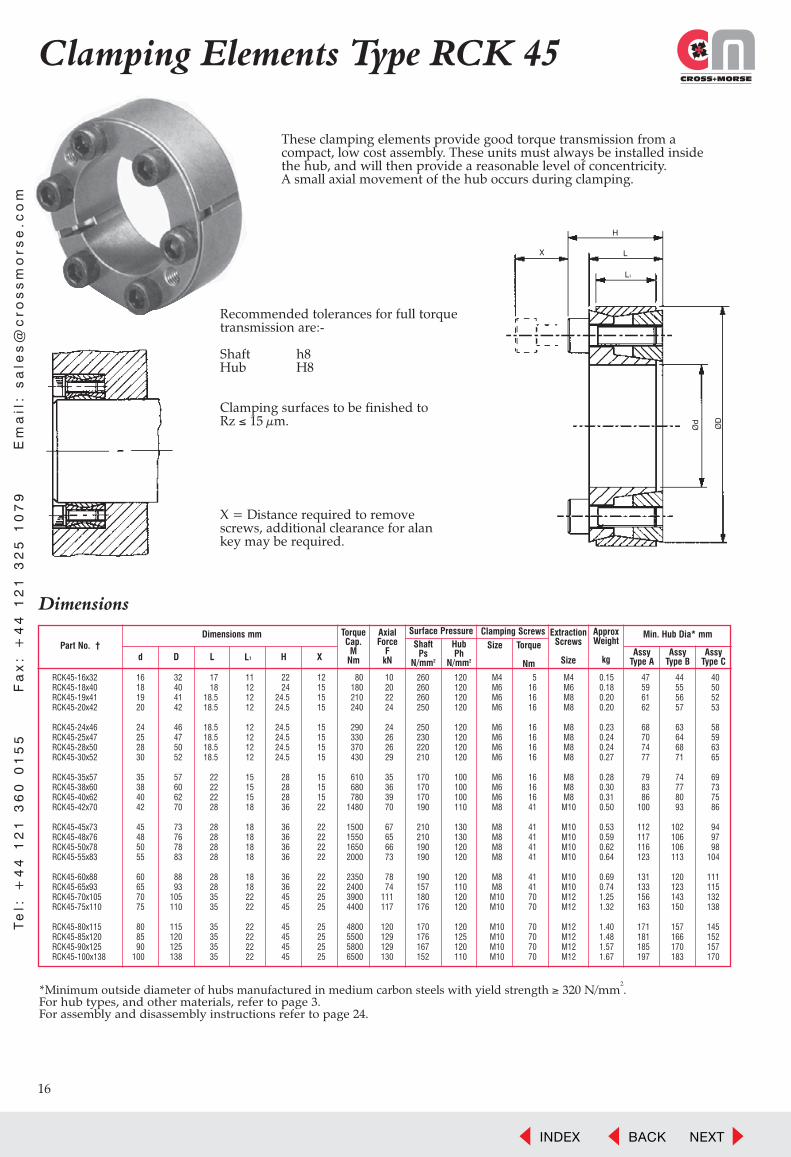
*Minimum outside diameter of hubs manufactured in medium carbon steels with yield strength ≥ 320 N/mm2.
For hub types, and other materials, refer to page 3.For assembly and disassembly instructions refer to page 24.
Clamping Elements Type RCK 45
These clamping elements provide good torque transmission from a compact, low cost assembly. These units must always be installed inside the hub, and will then provide a reasonable level of concentricity.A small axial movement of the hub occurs during clamping.
Dimensions
Recommended tolerances for full torquetransmission are:-
Shaft h8Hub H8
Clamping surfaces to be finished toRz ≤ 15 µm.
X = Distance required to removescrews, additional clearance for alankey may be required.
ØD
Ød
H
L
L1
X
Te
l: +
44
12
1 3
60
01
55
F
ax
: +
44
12
1 3
25
10
79
E
ma
il:
sa
les
@c
ros
sm
ors
e.c
om
16
XPart No. †
RCK45-16x32 16 32 17 11 22 12 80 10 260 120 M4 5 M4 0.15 47 44 40RCK45-18x40 18 40 18 12 24 15 180 20 260 120 M6 16 M6 0.18 59 55 50RCK45-19x41 19 41 18.5 12 24.5 15 210 22 260 120 M6 16 M8 0.20 61 56 52RCK45-20x42 20 42 18.5 12 24.5 15 240 24 250 120 M6 16 M8 0.20 62 57 53
RCK45-24x46 24 46 18.5 12 24.5 15 290 24 250 120 M6 16 M8 0.23 68 63 58RCK45-25x47 25 47 18.5 12 24.5 15 330 26 230 120 M6 16 M8 0.24 70 64 59RCK45-28x50 28 50 18.5 12 24.5 15 370 26 220 120 M6 16 M8 0.24 74 68 63RCK45-30x52 30 52 18.5 12 24.5 15 430 29 210 120 M6 16 M8 0.27 77 71 65
RCK45-35x57 35 57 22 15 28 15 610 35 170 100 M6 16 M8 0.28 79 74 69RCK45-38x60 38 60 22 15 28 15 680 36 170 100 M6 16 M8 0.30 83 77 73RCK45-40x62 40 62 22 15 28 15 780 39 170 100 M6 16 M8 0.31 86 80 75RCK45-42x70 42 70 28 18 36 22 1480 70 190 110 M8 41 M10 0.50 100 93 86
RCK45-45x73 45 73 28 18 36 22 1500 67 210 130 M8 41 M10 0.53 112 102 94RCK45-48x76 48 76 28 18 36 22 1550 65 210 130 M8 41 M10 0.59 117 106 97RCK45-50x78 50 78 28 18 36 22 1650 66 190 120 M8 41 M10 0.62 116 106 98RCK45-55x83 55 83 28 18 36 22 2000 73 190 120 M8 41 M10 0.64 123 113 104
RCK45-60x88 60 88 28 18 36 22 2350 78 190 120 M8 41 M10 0.69 131 120 111RCK45-65x93 65 93 28 18 36 22 2400 74 157 110 M8 41 M10 0.74 133 123 115RCK45-70x105 70 105 35 22 45 25 3900 111 180 120 M10 70 M12 1.25 156 143 132RCK45-75x110 75 110 35 22 45 25 4400 117 176 120 M10 70 M12 1.32 163 150 138
RCK45-80x115 80 115 35 22 45 25 4800 120 170 120 M10 70 M12 1.40 171 157 145RCK45-85x120 85 120 35 22 45 25 5500 129 176 125 M10 70 M12 1.48 181 166 152RCK45-90x125 90 125 35 22 45 25 5800 129 167 120 M10 70 M12 1.57 185 170 157RCK45-100x138 100 138 35 22 45 25 6500 130 152 110 M10 70 M12 1.67 197 183 170
Dimensions mm
d D L L1 H
TorqueCap.
MNm
AxialForce
FkN
ApproxWeight
kg
ExtractionScrews
Size
ShaftPs
N/mm2
HubPh
N/mm2
AssyType A
AssyType C
Size Torque
Nm
Surface Pressure Clamping Screws Min. Hub Dia* mm
AssyType B
INDEX BACK NEXT

17
Te
l: +4
4 1
21
36
0 0
15
5 F
ax
: +4
4 1
21
32
5 1
07
9 E
ma
il: sa
les
@c
ros
sm
ors
e.c
om
Clamping Elements Type RCK 61
Available for shaft diameters from 10mm, these clamping elements aredesigned for small low torque applications, providing concentric connectionof components to shafting. The thin wall design combined with low hubpressures enable use within small hub diameters. The design is intendedthat the units fit totally within the hub bore to provide safe surface. Some axial movement will occur when the units are clamped.
Recommended tolerances for full torquetransmission are:-
Shaft h8Hub H8
Clamping surfaces to be finished toRz ≤ 15 µm.
X = Distance required to removescrews, additional clearance for alankey may be required.
Clamping ScrewsSize
Surface PressureHubPh
N/mm2
ShaftPs
N/mm2XL1
Dimensions
Part No.Dimensions mm
d D L
TorqueCap.
MNm
AxialForce
FkN
ApproxWeight
kgAssy
Type AAssy
Type BAssy
Type C
Torque
Nm
Min. Hub Dia* mm
*Minimum outside diameter of hubs manufactured in medium carbon steels with yield strength ≥ 320 N/mm2.
For hub types, and other materials, refer to page 3.For assembly and disassembly instructions refer to page 24.
RCK61-5x16 5 16 13.5 11 10 5 2.0 176 55 M2.5 1.2 0.05 19 18 18RCK61-6x16 6 16 13.5 11 10 6 2.0 147 55 M2.5 1.2 0.05 19 18 18RCK61-7x17 7 17 13.5 11 10 8 2.3 134 55 M2.5 1.2 0.06 20 20 19RCK61-8x18 8 18 13.5 11 10 10 2.5 113 50 M2.5 1.2 0.07 21 20 20RCK61-9x20 9 20 15.5 13 12 15 3.3 122 55 M2.5 1.2 0.09 24 23 22
RCK61-10x20 10 20 15.5 13 12 19 3.8 90 45 M2.5 1.2 0.08 23 22 22RCK61-11x22 11 22 15.5 13 12 21 3.8 82 41 M2.5 1.2 0.09 25 24 24RCK61-12x22 12 22 15.5 13 12 23 3.8 75 41 M2.5 1.2 0.09 25 24 24RCK61-14x26 14 26 20 17 16 39 5.6 71 38 M3 2.1 0.12 29 29 28
RCK61-15x28 15 28 20 17 16 42 5.6 67 36 M3 2.1 0.13 31 31 30RCK61-16x32 16 32 21 17 16 77 9.6 108 54 M4 4.9 0.15 38 37 35RCK61-17x35 17 35 25 21 20 82 9.6 82 40 M4 4.9 0.21 40 39 38RCK61-18x35 18 35 25 21 20 87 10 78 40 M4 4.9 0.20 40 39 38
RCK61-19x35 19 35 25 21 20 91 10 74 40 M4 4.9 0.19 40 39 38RCK61-20x38 20 38 26 21 20 157 16 114 60 M5 9.7 0.21 46 44 43RCK61-22x40 22 40 26 21 20 173 16 104 57 M5 9.7 0.22 48 46 45RCK61-24x47 24 47 32 26 24 268 22 110 56 M6 17 0.31 56 54 52
RCK61-25x47 25 47 32 26 24 279 22 105 56 M6 17 0.30 56 54 52RCK61-28x50 28 50 32 26 24 468 33 141 79 M6 17 0.33 64 61 58RCK61-30x55 30 55 32 26 24 502 33 132 72 M6 17 0.40 69 66 63RCK61-32x55 32 55 32 26 24 535 33 124 72 M6 17 0.38 69 66 63
RCK61-35x60 35 60 37 31 28 781 45 125 73 M6 17 0.54 76 72 69RCK61-38x65 38 65 37 31 28 848 45 115 67 M6 17 0.63 80 77 74RCK61-40x65 40 65 37 31 28 892 45 109 67 M6 17 0.59 80 77 74RCK61-42x75 42 75 44 36 34 1272 61 121 68 M8 41 1.00 93 89 85
RCK61-45x75 45 75 44 36 34 1363 61 113 68 M8 41 0.95 93 89 85RCK61-48x80 48 80 44 36 34 1938 81 142 85 M8 41 1.07 105 99 94RCK61-50x80 50 80 44 36 34 2019 81 136 85 M8 41 1.02 105 99 94
INDEX BACK NEXT

Te
l: +
44
12
1 3
60
01
55
F
ax
: +
44
12
1 3
25
10
79
E
ma
il:
sa
les
@c
ros
sm
ors
e.c
om
18
RCK50-6x9RCK50-7x10RCK50-8x11RCK50-9x12
RCK50-10x13RCK50-12x15RCK50-13x16RCK50-14x18
RCK50-15x19RCK50-16x20RCK50-17x21RCK50-18x22
RCK50-19x24RCK50-20x25RCK50-22x26RCK50-24x28
RCK50-25x30RCK50-28x32RCK50-30x35RCK50-32x36
RCK50-35x40RCK50-36x42RCK50-38x44RCK50-40x45
RCK50-42x48RCK50-45x52RCK50-48x55RCK50-50x57
RCK50-55x62RCK50-56x24RCK50-60x68RCK50-63x71
RCK50-65x73RCK50-70x79RCK50-71x80RCK50-75x84RCK50-80x91
6789
10121314
15161718
19202224
25283032
35363840
42454850
55566063
6570717580
9101112
13151618
19202122
24252628
30323536
40424445
48525557
62646871
7379808491
4.54.54.54.5
4.54.54.56.3
6.36.36.36.3
6.36.36.36.3
6.36.36.36.3
7778
8101010
10121212
1214141417
3.73.73.73.7
3.73.73.75.3
5.35.35.35.3
5.35.35.35.3
5.35.35.35.3
6.06.06.06.6
6.68.68.68.6
8.610.410.410.4
10.412.212.212.214.8
2.43.04.77.9
9.511.413.122.3
24.327.329.832.4
49.053.066.073.0
72.086.091.0
131.0
171.0169.0181.0231.0
235.0390.0572.0602.0
670.0790.0860.0945.0
10001300134015002100
0.80.91.21.8
1.91.92.03.2
3.23.43.53.6
5.25.36.06.1
5.86.16.18.2
9.89.49.5
11.6
11.219.023.824.1
24.428.228.730.0
30.837.137.740.052.5
115105120140
135115110115
110105105100
140135135130
115115100130
125115110115
110116155150
140130125125
125125125125125
757090
105
105909090
85858580
110105115110
95100
85115
110100
95105
95105135130
125115110110
110110110110110
1.21.41.51.7
1.82.22.34.9
5.35.55.86.1
7.88.27.38.0
10.19.2
12.010.0
17.020.021.023.0
28.042.045.047.0
50.067.072.076.0
78110114118187
11.512.514.716.9
18.320.121.424.1
25.026.327.628.5
34.435.237.940.1
40.844.346.052.5
57.358.159.863.3
65.273.286.387.8
93.793.397.4
101.6
104.5113.1114.5120.2130.3
10.912.013.915.8
17.118.920.222.7
23.624.926.127.1
31.932.835.037.2
38.341.443.548.4
53.154.356.158.9
61.268.178.279.9
85.786.190.294.2
96.9104.8106.1111.4120.7
3.83.95.3
15.6
15.615.615.625.4
25.425.425.425.4
36.036.036.036.0
36.036.036.045.0
54.054.054.066.0
66.0110.0132.0132.0
132.0158.0158.0160.0
160200200220300
Clamping Elements Type RCK 50
These shaft clamping elements consist of just two conical rings whichrequire the minimum of radial space, so providing compact assemblies, andenabling use within small hub diameters. The design offers the maximumversatility of design, but does require the customer to provide their ownthrust ring assembly. Whilst only providing low torque transmission perunit they can be combined (up to 4 units) to increase torque capacity. Whenfully clamped these units provide excellent gastight sealing. Many designsof thrust rings are possible and sketches to the left are two typical designs.These units do not self centre, so require external means of centring thehub.
Dimensions
Part No. †
10.411.513.114.7
15.917.819.021.4
22.423.524.725.6
29.630.632.434.6
36.038.741.244.9
49.450.852.755.0
57.563.571.373.1
78.879.783.987.6
90.097.498.7
103.6112.2
Dimensions mm
d D L L1
TorqueCap.
MNm
AxialForce
FkN
Axial Forcenecessaryto clamp
kN
Approx.Weight
gms
ShaftPs
N/mm2
HubPh
N/mm2Assy
Type AAssy
Type BAssy
Type C
Surface Pressure Min. Hub Dia* mm
*Minimum outside diameter of hubs manufactured in medium carbon steels with yield strength ≥ 320 N/mm2.
For hub types, and other materials, refer to page 3.For assembly and disassembly instructions refer to page 24.
† Clamping Rings for shafts up to 200mm diameter are available to order.
Recommended tolerances for full torque transmission are:-
Up to 38m shaft Ø:- Shaft h6Hub H7
40mm and above shaft Ø:- Shaft h8Hub H8
Clamping surfaces to be finished to Rz ≤ 15 µm.
Factor for combining elements in one assembly.
Number of Elements Torque Capacity2 1.55M Nm3 1.86M Nm4 2.03M Nm
INDEX BACK NEXT

Locking NutThread
Surface PressureHubPh
N/mm2
ShaftPs
N/mm2L L1
19
Clamping Elements TypesCCE 54 and CCE 55
These clamping elements use a single lock nut to apply the clamping pressure, thereby enabling quick assembly and removal. The lock nut canbe secured in postition by bending over a tab of lock washer. The thin wallsof the clamping cones, combined with low hub pressures enables use withsoft materials, such as aluminium, and small hub diameters.
Dimensions
Part No.Dimensions mm
d D D2
TorqueCap.
MNm
AxialForce
FkN
TypeAssy
Type AAssy
Type BAssy
Type C
Torque
Nm
Min. Hub Dia* mm
Use type CCE 54 where axial space is restricted and torque is low.
Type CCE 55 is for higher torque transmission.
Recommended tolerances for full torque transmission are:-
Shaft h8Hub H8
Clamping surfaces to be finished toRz ≤ 15 µm.
*Minimum outside diameter of hubs manufactured in medium carbon steels with yield strength ≥ 320 N/mm2.
For hub types, and other materials, refer to page 3.For assembly and disassembly instructions refer to page 24.
Te
l: +4
4 1
21
36
0 0
15
5 F
ax
: +4
4 1
21
32
5 1
07
9 E
ma
il: sa
les
@c
ros
sm
ors
e.c
om
CCE54-14x25 14 25 32 16.5 6.5 52 7 241 135 KM4 M20 95 39 36 32CCE54-15x25 15 25 32 16.5 6.5 56 7 225 135 KM4 M20 95 39 36 32CCE54-16x25 16 25 32 16.5 6.5 60 8 211 135 KM4 M20 95 39 36 32CCE54-17x25 17 25 38 17.5 6.5 63 7 118 80 KM5 M25 160 32 31 29CCE54-18x30 18 30 38 17.5 6.5 91 10 257 154 KM5 M25 160 51 45 40
CCE54-19x30 19 30 38 17.5 6.5 96 10 243 154 KM5 M25 160 51 45 40CCE54-20x30 20 30 38 17.5 6.5 102 10 231 154 KM5 M25 160 51 45 40CCE54-24x35 24 35 45 17.5 6.5 139 12 219 150 KM6 M30 220 58 52 47CCE54-25x35 25 35 45 17.5 6.5 144 12 210 150 KM6 M30 220 58 52 47CCE54-28x40 28 40 52 18.5 6.5 215 15 249 174 KM7 M35 340 74 64 56
CCE54-30x40 30 40 52 20.0 8.0 230 15 188 141 KM7 M35 340 64 58 52CCE54-32x45 32 45 58 22.0 9.0 210 13 113 80 KM8 M40 320 58 55 52CCE54-35x45 35 45 58 22.0 9.0 331 19 199 155 KM8 M40 480 76 68 61CCE54-40x50 40 50 65 25.0 10.0 477 24 176 141 KM9 M45 680 80 72 66CCE54-45x55 45 55 70 26.0 10.0 617 27 180 147 KM10 M50 870 90 81 73
CCE54-48x60 48 60 75 26.0 10.0 669 28 171 137 KM11 M55 970 95 86 78CCE54-50x60 50 60 75 26.0 10.0 697 28 164 137 KM11 M55 970 95 86 78CCE54-55x65 55 65 80 28.0 12.0 796 29 129 109 KM12 M60 1100 93 86 80CCE54-60x70 60 70 85 29.0 12.0 946 32 130 111 KM13 M65 1300 101 93 86CCE54-70x84 70 84 98 29.5 13.5 1433 41 127 106 KM15 M75 2000 119 110 103
CCE55-14x25 14 25 32 29 17 90 13 143 80 KM4 M20 90 32 31 29CCE55-15x25 15 25 32 29 17 100 13 133 80 KM4 M20 90 32 31 29CCE55-16x25 16 25 32 29 17 80 10 94 60 KM4 M20 70 30 29 28CCE55-17x25 17 25 38 31 18 113 13 103 70 KM5 M25 90 31 30 29
CCE55-18x30 18 30 38 33 20 100 11 75 45 KM5 M25 160 35 34 33CCE55-19x30 19 30 38 33 20 105 11 71 45 KM5 M25 160 35 34 33CCE55-20x30 20 30 38 33 20 112 11 68 45 KM5 M25 160 35 34 33CCE55-24x35 24 35 45 38 25 178 15 66 45 KM6 M30 220 40 39 38CCE55-25x35 25 35 45 38 25 185 15 63 45 KM6 M30 220 40 39 38
CCE55-28x40 28 40 52 44 30 250 18 57 40 KM7 M35 340 45 44 43CCE55-30x40 30 40 52 44 30 270 18 53 40 KM7 M35 340 45 44 43CCE55-32x45 32 45 58 4 28 420 26 98 70 KM8 M40 320 56 54 51CCE55-35x45 35 45 58 45 30 390 22 58 45 KM8 M40 480 52 50 49
CCE55-40x50 40 50 65 46 30 620 31 56 45 KM9 M45 680 58 56 54CCE55-45x55 45 55 70 47 30 580 26 61 50 KM10 M50 870 64 62 60CCE55-50x60 50 60 75 47 30 880 35 60 50 KM11 M55 970 70 68 66CCE55-55x65 55 65 80 48 30 1030 37 59 50 KM12 M60 1100 76 74 71CCE55-60x70 60 70 85 50 30 1360 45 64 55 KM13 M65 1300 83 80 78
INDEX BACK NEXT
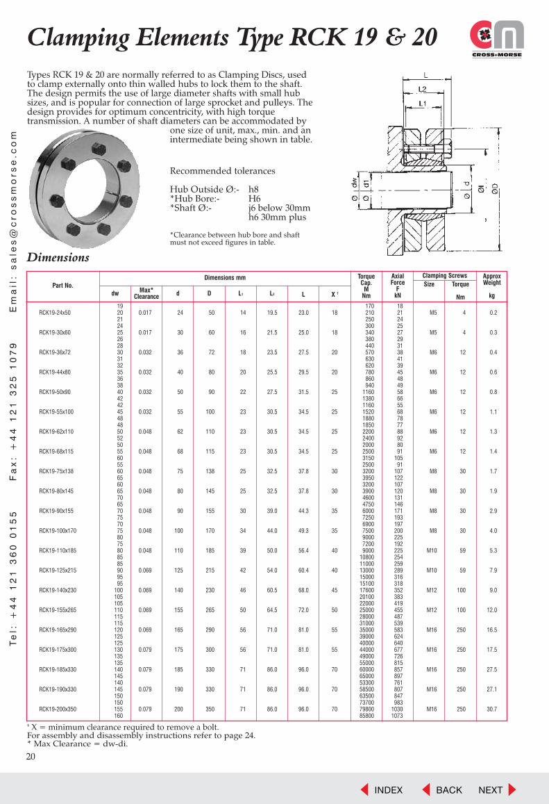
20
Clamping Elements Type RCK 19 & 20Types RCK 19 & 20 are normally referred to as Clamping Discs, usedto clamp externally onto thin walled hubs to lock them to the shaft.The design permits the use of large diameter shafts with small hubsizes, and is popular for connection of large sprocket and pulleys. Thedesign provides for optimum concentricity, with high torquetransmission. A number of shaft diameters can be accommodated by
one size of unit, max., min. and anintermediate being shown in table.
Dimensions
Part No.Dimensions mm
dw Max*Clearance d D LL1 L2 X †
TorqueCap.
MNm
AxialForce
FkN
ApproxWeight
kg
Size Torque
Nm
Clamping Screws
Recommended tolerances
Hub Outside Ø:- h8*Hub Bore:- H6*Shaft Ø:- j6 below 30mm
h6 30mm plus
*Clearance between hub bore and shaftmust not exceed figures in table.
Te
l: +
44
12
1 3
60
01
55
F
ax
: +
44
12
1 3
25
10
79
E
ma
il:
sa
les
@c
ros
sm
ors
e.c
om
19 170 18RCK19-24x50 20 0.017 24 50 14 19.5 23.0 18 210 21 M5 4 0.2
21 250 2424 300 25
RCK19-30x60 25 0.017 30 60 16 21.5 25.0 18 340 27 M5 4 0.326 380 2928 440 31
RCK19-36x72 30 0.032 36 72 18 23.5 27.5 20 570 38 M6 12 0.431 630 4132 620 39
RCK19-44x80 35 0.032 40 80 20 25.5 29.5 20 780 45 M6 12 0.636 860 4838 940 49
RCK19-50x90 40 0.032 50 90 22 27.5 31.5 25 1160 58 M6 12 0.842 1380 6642 1160 55
RCK19-55x100 45 0.032 55 100 23 30.5 34.5 25 1520 68 M6 12 1.148 1880 7848 1850 77
RCK19-62x110 50 0.048 62 110 23 30.5 34.5 25 2200 88 M6 12 1.352 2400 9250 2000 80
RCK19-68x115 55 0.048 68 115 23 30.5 34.5 25 2500 91 M6 12 1.460 3150 10555 2500 91
RCK19-75x138 60 0.048 75 138 25 32.5 37.8 30 3200 107 M8 30 1.765 3950 12260 3200 107
RCK19-80x145 65 0.048 80 145 25 32.5 37.8 30 3900 120 M8 30 1.970 4600 13165 4750 146
RCK19-90x155 70 0.048 90 155 30 39.0 44.3 35 6000 171 M8 30 2.975 7250 19370 6900 197
RCK19-100x170 75 0.048 100 170 34 44.0 49.3 35 7500 200 M8 30 4.080 9000 22575 7200 192
RCK19-110x185 80 0.048 110 185 39 50.0 56.4 40 9000 225 M10 59 5.385 10800 25485 11000 259
RCK19-125x215 90 0.069 125 215 42 54.0 60.4 40 13000 289 M10 59 7.995 15000 31695 15100 318
RCK19-140x230 100 0.069 140 230 46 60.5 68.0 45 17600 352 M12 100 9.0105 20100 383105 22000 419
RCK19-155x265 110 0.069 155 265 50 64.5 72.0 50 25000 455 M12 100 12.0115 28000 487115 31000 539
RCK19-165x290 120 0.069 165 290 56 71.0 81.0 55 35000 583 M16 250 16.5125 39000 624125 40000 640
RCK19-175x300 130 0.079 175 300 56 71.0 81.0 55 44000 677 M16 250 17.5135 49000 726135 55000 815
RCK19-185x330 140 0.079 185 330 71 86.0 96.0 70 60000 857 M16 250 27.5145 65000 897140 53300 761
RCK19-190x330 145 0.079 190 330 71 86.0 96.0 70 58500 807 M16 250 27.1150 63500 847150 73700 983
RCK19-200x350 155 0.079 200 350 71 86.0 96.0 70 79800 1030 M16 250 30.7160 85800 1073
† X = minimum clearance required to remove a bolt.For assembly and disassembly instructions refer to page 24.* Max Clearance = dw-di.
INDEX BACK NEXT

21
Clamping Elements Type RCK 19 & 20T
el: +
44
12
1 3
60
01
55
Fa
x: +
44
12
1 3
25
10
79
Em
ail: s
ale
s@
cro
ss
mo
rse
.co
m
† X = minimum clearance required to remove a bolt.For assembly and disassembly instructions refer to page 24.* Max Clearance = dw-di.
Dimensions
Part No.Dimensions mm
dw Max*Clearance d D LL1 L2 X †
TorqueCap.
MNm
AxialForce
FkN
ApproxWeight
kg
Size Torque
Nm
Clamping Screws
160 95000 1188RCK19-220x370 165 0.079 220 370 88 104 114 85 102000 1236 M16 250 40.8
170 110000 1294170 120000 1412
RCK19-240x405 180 0.090 240 405 92 109 121 90 140000 1556 M20 490 51.3190 160000 1684190 165000 1737
RCK19-260x430 200 0.090 260 430 103 120 132 100 185000 1850 M20 490 63.3210 204000 1943210 216000 2057
RCK19-280x460 220 0.090 280 460 114 134 147 112 245000 2227 M20 490 79.6230 270000 2348230 274000 2383
RCK19-300x485 240 0.090 300 485 122 142 155 120 296000 2467 M20 490 92.8245 316000 2580250 352000 2816
RCK19-330x520 260 0.101 330 520 122 142 155 120 385000 2962 M20 490 103270 420000 3111270 443000 3281
RCK19-350x580 280 0.101 350 580 140 162 175 140 480000 3429 M20 490 157285 500000 3509290 570000 3931
RCK19-380x645 300 0.101 380 645 144 168 183 140 610000 4067 M24 840 205310 660000 4258315 671000 4260
RCK19-400x680 320 0.111 400 680 144 168 183 140 695000 4344 M24 840 228330 745000 4515330 782000 4739
RCK19-420x690 340 0.111 420 690 164 188 203 160 841000 4947 M24 840 258350 902000 5154340 805000 4735
RCK19-440x750 350 0.111 440 750 177 202 217 175 861000 4920 M24 840 342360 920000 5111360 1000000 5556
RCK19-460x800 370 0.111 460 800 177 202 217 175 1073000 5800 M24 840 397380 1141000 6005380 1175000 6184
RCK19-480x800 390 0.111 480 800 188 213 228 185 1250000 6410 M24 840 404400 1312000 6560400 1314000 6570
RCK19-500x850 410 0.123 500 850 188 213 230 185 1382000 6741 M27 1250 466420 1460000 6952135 73000 1081
RCK20-185x330 140 0.079 185 330 92 112 122 90 79000 1129 M16 250 36.0145 87000 1200150 93000 1240
RCK20-200x350 155 0.079 200 350 92 112 122 90 105000 1355 M16 250 39.8160 115000 1438160 128000 1600
RCK20-220x370 165 0.079 220 370 114 134 144 110 137000 1661 M16 250 52.9170 147000 1729170 157000 1847
RCK20-240x405 180 0.090 240 405 120 144 157 120 178000 1978 M20 490 66.9190 199000 2095190 215000 2263
RCK20-260x430 200 0.090 260 430 136 160 173 135 242000 2420 M20 490 83.6210 269000 2562210 286000 2724
RCK20-280x460 220 0.090 280 460 148 172 185 145 322000 2927 M20 490 103230 356000 3096230 342000 2974
RCK20-300x485 240 0.090 300 485 152 176 189 150 377000 3142 M20 490 116250 402000 3216250 490000 3920
RCK20-340x570 260 0.101 340 570 176 200 215 175 531000 4085 M24 840 193270 579000 4289270 557000 4126
RCK20-350x580 280 0.101 350 580 176 200 215 175 605000 4321 M24 840 197290 630000 4345290 619000 4269
RCK20-380x645 300 0.101 380 645 180 204 219 180 669000 4460 M24 840 256310 720000 4645310 752000 4852
RCK20-400x680 320 0.111 400 680 188 212 227 185 789000 4931 M24 840 298330 846000 5127330 1000000 6061
RCK20-420x690 340 0.111 420 690 214 238 253 210 1070000 6294 M24 840 336350 1142000 6526340 1059000 6229
RCK20-440x750 350 0.111 440 750 224 252 269 220 1132000 6469 M27 1250 433360 1205000 6694360 1321000 7339
RCK20-460x770 370 0.111 460 770 224 252 269 220 1422000 7686 M27 1250 448380 1502000 7905380 1540000 8105
RCK20-480x800 390 0.111 480 800 246 274 291 240 1630000 8359 M27 1250 528400 1724000 8620400 1752000 8760
RCK20-500x850 410 0.123 500 850 246 274 291 240 1842000 8985 M27 1250 609420 1943000 9252
INDEX BACK NEXT
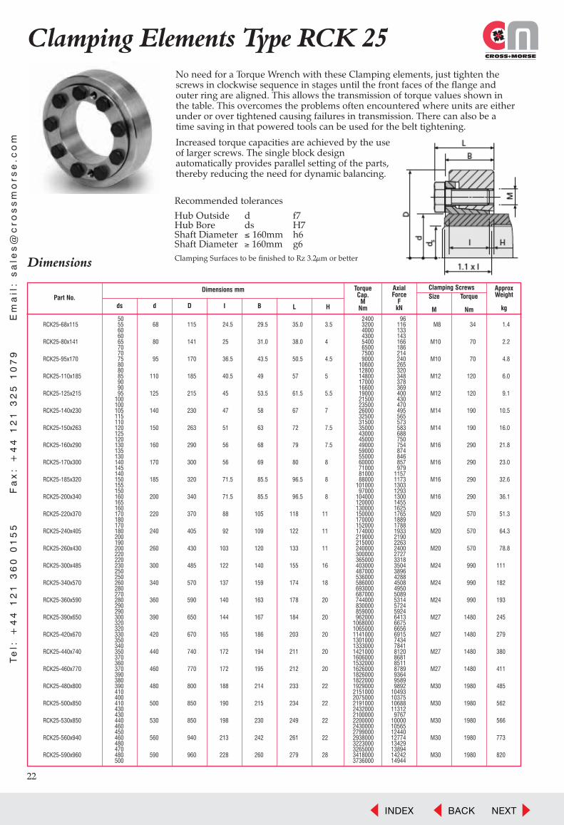
22
Clamping Elements Type RCK 25No need for a Torque Wrench with these Clamping elements, just tighten thescrews in clockwise sequence in stages until the front faces of the flange andouter ring are aligned. This allows the transmission of torque values shown in the table. This overcomes the problems often encountered where units are eitherunder or over tightened causing failures in transmission. There can also be a time saving in that powered tools can be used for the belt tightening.
Increased torque capacities are achieved by the useof larger screws. The single block design automatically provides parallel setting of the parts,thereby reducing the need for dynamic balancing.
Dimensions
Part No.Dimensions mm
ds d D LI B H
TorqueCap.
MNm
AxialForce
FkN
ApproxWeight
kg
Size
M
Torque
Nm
Clamping Screws
Recommended tolerances
Hub Outside d f7Hub Bore ds H7Shaft Diameter ≤ 160mm h6Shaft Diameter ≥ 160mm g6Clamping Surfaces to be finished to Rz 3.2µm or better
Te
l: +
44
12
1 3
60
01
55
F
ax
: +
44
12
1 3
25
10
79
E
ma
il:
sa
les
@c
ros
sm
ors
e.c
om
50 2400 96RCK25-68x115 55 68 115 24.5 29.5 35.0 3.5 3200 116 M8 34 1.4
60 4000 13360 4300 143
RCK25-80x141 65 80 141 25 31.0 38.0 4 5400 166 M10 70 2.270 6500 18670 7500 214
RCK25-95x170 75 95 170 36.5 43.5 50.5 4.5 9000 240 M10 70 4.880 10600 26580 12800 320
RCK25-110x185 85 110 185 40.5 49 57 5 14800 348 M12 120 6.090 17000 37890 16600 369
RCK25-125x215 95 125 215 45 53.5 61.5 5.5 19000 400 M12 120 9.1100 21500 430100 23500 470
RCK25-140x230 105 140 230 47 58 67 7 26000 495 M14 190 10.5115 32500 565110 31500 573
RCK25-150x263 120 150 263 51 63 72 7.5 35000 583 M14 190 16.0125 43000 688120 45000 750
RCK25-160x290 130 160 290 56 68 79 7.5 49000 754 M16 290 21.8135 59000 874130 55000 846
RCK25-170x300 140 170 300 56 69 80 8 60000 857 M16 290 23.0145 71000 979140 81000 1157
RCK25-185x320 150 185 320 71.5 85.5 96.5 8 88000 1173 M16 290 32.6155 101000 1303150 97000 1293
RCK25-200x340 160 200 340 71.5 85.5 96.5 8 104000 1300 M16 290 36.1165 120000 1455160 130000 1625
RCK25-220x370 170 220 370 88 105 118 11 150000 1765 M20 570 51.3180 170000 1889170 152000 1788
RCK25-240x405 180 240 405 92 109 122 11 174000 1933 M20 570 64.3200 219000 2190190 215000 2263
RCK25-260x430 200 260 430 103 120 133 11 240000 2400 M20 570 78.8220 300000 2727220 365000 3318
RCK25-300x485 230 300 485 122 140 155 16 403000 3504 M24 990 111250 487000 3896250 536000 4288
RCK25-340x570 260 340 570 137 159 174 18 586000 4508 M24 990 182280 693000 4950270 687000 5089
RCK25-360x590 280 360 590 140 163 178 20 744000 5314 M24 990 193290 830000 5724290 859000 5924
RCK25-390x650 300 390 650 144 167 184 20 962000 6413 M27 1480 245320 1068000 6675320 1065000 6656
RCK25-420x670 330 420 670 165 186 203 20 1141000 6915 M27 1480 279350 1301000 7434340 1333000 7841
RCK25-440x740 350 440 740 172 194 211 20 1421000 8120 M27 1480 380370 1606000 8681360 1532000 8511
RCK25-460x770 370 460 770 172 195 212 20 1626000 8789 M27 1480 411390 1826000 9364380 1822000 9589
RCK25-480x800 390 480 800 188 214 233 22 1929000 9892 M30 1980 485410 2151000 10493400 2075000 10375
RCK25-500x850 410 500 850 190 215 234 22 2191000 10688 M30 1980 562430 2432000 11312430 2100000 9767
RCK25-530x850 440 530 850 198 230 249 22 2200000 10000 M30 1980 566460 2430000 10565450 2799000 12440
RCK25-560x940 460 560 940 213 242 261 22 2938000 12774 M30 1980 773480 3223000 13429470 3265000 13894
RCK25-590x960 480 590 960 228 260 279 28 3418000 14242 M30 1980 820500 3736000 14944
INDEX BACK NEXT

23
Te
l: +4
4 1
21
36
0 0
15
5 F
ax
: +4
4 1
21
32
5 1
07
9 E
ma
il: sa
les
@c
ros
sm
ors
e.c
om
Clamping Elements Type RCK 95
Similar in design to the Clamping Discs, type RCK 19, but with the discsspaced further apart to enable connection to more than one shaft, enablinguse as a rigid shaft coupling. These units can be used to connect twoidentical diameter shafts which are perfectly aligned, or to produce a longershaft which is only mounted in two bearings. Torque capacities are suitablefor standard shafting. These units provide zero backlash shaft connectionwith advantage of fast assembly and disassembly. The design makes theunit equally suitable for horizontal and vertical shafts, capable ofwithstanding high axial loads.
For assembly and disassembly instructions refer to page 24.
Dimensions
Part No.
RCK95-17x50 17 50 56 50 200 21 110 M6 17 0.46RCK95-18x50 18 50 56 50 220 22 110 M6 17 0.45RCK95-19x50 19 50 56 50 230 22 110 M6 17 0.44RCK95-20x50 20 50 56 50 240 22 105 M6 17 0.44
RCK95-24x55 24 55 66 60 290 22 120 M6 17 0.63RCK95-25x55 25 55 66 60 450 32 110 M6 17 0.65RCK95-28x60 28 60 66 60 510 33 110 M6 17 0.75RCK95-30x60 30 60 66 60 550 33 105 M6 17 0.71
RCK95-32x63 32 63 66 60 580 33 90 M6 17 0.73RCK95-35x75 35 75 83 75 760 39 105 M8 41 1.33RCK95-38x75 38 75 83 75 850 40 100 M8 41 1.20RCK95-40x75 40 75 83 75 900 41 95 M8 41 1.19
RCK95-42x78 42 78 83 75 930 40 90 M8 41 1.28RCK95-45x85 45 85 93 85 1520 61 110 M8 41 1.72RCK95-48x90 48 90 93 85 1600 60 100 M8 41 1.90RCK95-50x90 50 90 93 85 1690 61 95 M8 41 1.88
RCK95-55x94 55 94 93 85 2430 80 110 M8 41 2.00RCK95-60x100 60 100 93 85 2680 80 95 M8 41 2.17RCK95-65x105 65 105 93 85 2900 80 90 M8 41 3.95RCK95-70x115 70 115 110 100 3720 96 90 M10 83 5.25
RCK95-75x125 75 125 110 100 3970 95 80 M10 83 5.46RCK95-80x125 80 125 110 100 4280 96 70 M10 83 5.30RCK95-90x135 90 135 110 100 5400 108 70 M10 83 5.60RCK95-100x155 100 155 132 120 8700 157 100 M12 143 7.00
Dimensions mm
d D L L1
TorqueCap.
MNm
AxialForce
FkN
ApproxWeight
gms
Shaft SurfacePressure
PsN/mm2
Size Torque
Nm
Clamping Screws
Recommended tolerances for full torque transmission shaftsshould be to h8 tolerance with surface finish Rz ≤ 15 µm.
WarningThe units are not flexiblecouplings, and must never beused as such. Any radial loadson shafts must be adequatelysupported by bearingassemblies.
INDEX BACK NEXT

24
Installation Instructions
Installation and Removal of Cross Shaft Clamping Elements
Types RCK 10, 11, 12, 13, 15, 16, 61, 70, 71, 80 and ACE81Installation:-1. Slacken all screws in element by approx. two turns.2. Remove two or three screws completely, and fit into equally spaced
sempty release thread holes. Tighten these screws lightly so as to ensure inner and outer cones are kept apart.
3. Clean all contact surfaces including screw threads, and lightly oil with clean thin unmodified oil.*
4. Insert clamping element into hub and push onto shaft and locate.5. Remove screws from release holes and replace in original holes.6. Tighten all screws finger tight and align hub.7. Tighten all screws evenly in a diametrically opposite sequence
(see typical progression in sketch) using a torque wrench, initially at halfscrew catalogue torque, then 3/4 value, and finally full torque. Check all screws at full torque until no further rotation of screws occurs.
Disassembly:-1. Slacken all clamping screws by couple of turns, completely removing as many as release holes in element.2. Fit screws in release holes and tighten in sequence as clamping to force inner and outer cones apart.3. Carefully remove hub and clamping element from shaft, and take element from hub.
Types RCK 40 and 45Installation:-1. Clean all contact surfaces, and lightly oil with clean thin unmodified mineral oil.*2. Fit hub to shaft and insert clamping element.3. Tighten all screws finger tight and align hub.4. Tighten all screws evenly in a diametrically opposite sequence (see typical progression in sketch) using a torque wrench,
initially at half catalogue torque for screw, then at 3/4 value, and finally at full torque. Check all screws are at full torqueuntil no further rotation of screws can be achieved.
Disassembly:-1. Release clamping screws in same sequence as for clamping. Element should now self release. If required lightly
tap clamping screws to aid release. If still not released remove light coloured screws completely and replace with next larger metric size and tighten these screws to jack the cones apart.
Type RCK 50Installation procedure depends detailed design, but following is typical:-1. Clean all contact surfaces, and lightly oil with clean thin unmodified mineral oil.*2. Push hub onto shaft and insert spacer sleeves and clamping ring sets according to application drawing.3. Insert distance ring if fitted and attach clamping flange lightly tightening screws. Align hub.4. Tighten all screws in a diametrically opposite sequence, in several stages up to max. torque for screw size.
Disassembly:-The taper of the individual rings is such that the assembly should automatically release when the locking screwsare slackened. If not light tapping on the hub circumference should release them.
Types CCE 54 and 55Installation:-1. Clean all contact surfaces, and lightly oil with clean unmodified mineral oil.*2. Turn locking nut anticlockwise until outer sleeve loose on inner cone.3. Position hub on shaft and insert clamping element.4. Align hub and tighten locking nut to catalogue torque value, and bend suitable tab on lock washer to prevent
further rotation.
Disassembly:-1. Release bent washertab and undo nut until sleeve loose.2. Remove clamping element, If tight give end of tab gentle tap to release.
Types RCK 19/20 and 95Installation:-1. Clean all contact surfaces, and lightly oil with clean thin unmodified mineral oil.*2. Slacken all clamping bolts by a couple of turns.3. (RCK 19/20 only) Fit clamping element on outer diameter of hub, and slide assembly onto shaft and position.
(RCK 95 only) Fit shaft ends equally into clamping element ensuring small clearance between shafts.4. Tighten all bolts in a diametrically opposite sequence, in several stages up to max. specified torque.
Disassembly:-Slacken all bolts and gently tap on bolts to release clamping element.
*WARNING: Never use, lubricant containing Molydenum or E.P. additives, synthetic lubricant, or grease.
19
3
7
52
10
4
8
6
Te
l: +
44
12
1 3
60
01
55
F
ax
: +
44
12
1 3
25
10
79
E
ma
il:
sa
les
@c
ros
sm
ors
e.c
om
INDEX BACK NEXT

Formulae and Conversion Factors
1. Motor Power (kw) P = T � n9550
2. Torque (Nm) T = 9550Pn
3. For Solid Cylinder Inertia (kg m2) I = md2
� 10-4 = � lqd4
� 10-6
800 32000
4. For Hollow Cylinder Inertia (kg m2) I = m(da2 � di2 ) � 10-4 = � lq (da4 � di4)
� 10-6
800 32000
5. Flywheel Inertia GD2 (kp m2) � 4 � I
6. Acceleration Torque (Nm) Ta = 0.105 It (n2 � n1)
ta
7. Total drive Torque (Nm) Tt = Ta + TL
alsoTt = KTs + TL
where K = IL + It
1 + K Id
8. Tooth & Belt/Chain drive speed m/Sec V =Z � p � n
60,000
9. Pull in Belt/chain (N) FL =P � 1000
V
10. Centrifugal Pull Belt/Chain FC = WV2
Useful formulae in Power Transmission Calculations
Whered = diameter - mm p = chain/belt pitch - mmda = outside diameter - mm P = Power - kwdi = inside diameter - mm q = density - kg/cm3
Fc = Centrifugal - Newtons ta = time acceleration - secsFL = Load (Power) Pull - Newtons T = Torque - NmI = Inertia - kgm2 Ta = Acceleration Torque - NmId = Inertia of Driver - kgm2 TL = Load Torque - NmIL = Inertia of Load - kgm2 Ts = Motor Starting Torque - NmIt = Total Inertia - kgm2 Tt = Total Torque - Nml = length - mm V = Velocity - m/Secm = mass - kg W = Weight - kg/mn = rotational speed - r.p.m. Z = No. Teeth in Pulleyn2 �n1 = change in speed - r.p.m.
Conversion Factors
LENGTH mm � 0.03937 = INCHES � 25.4 = mmMETRES � 3.2808 = FEET � 0.3048 = METRES
WEIGHT kg � 2.2046 = POUND f � 0.4536 = kg
FORCE N (Newton) � 0.2248 = POUND f � 4.4482 = NN (Newton) � 0.1019 = kg f � 9.807 = N
TORQUE Nm � 0.7376 = lb f ft � 1.356 = Nmkgfm � 9.8066 = Nm � 0.1019 = kgfm
POWER kW � 1.341 = HP � 0.7457 = kWkW � 1.3596 = PS � 0.7355 = kW
INERTIA kgm2 � 23.7304 = lb f ft2 � 0.04214 = kgcm2
kgcm2 � 10-4 = kg m2 � 10,000 = kgcm2
kgcm2 � 0.3417 = lb in2 � 2.9264 = kgcm2
GD2kpm � 0.25 = kg m2 � 4.0 = kpm
INDEX BACK NEXT
Shady Lane, Great Barr, Birmingham,England B44 9EU
Telephone: +44(0)121 360 0155Sales Direct: +44(0)121 325 2500
Facsimile: +44(0)121 325 1079Email: [email protected]: www.crossmorse.com
Power Transmission ProductsRoller Chain DrivesTiming Belt DrivesSilent Chain DrivesClamping ElementsOverload ClutchesTorque LimitersMounted BearingsStieber FreewheelsShaft CouplingsSprag ClutchesTensionersSprocketsPulleysGears
SCE2011©T.D.Cross Ltd.
8
33904 Cross & Morse Shaft Clamping Cover:33904 Cross & Morse Shaft Clamping Cover 12/5/11 10:01 Page 2
INDEX BACK NEXT