Serpentine Solar Design Manual - Engineering for Change
36
1 DESIGN MANUAL DIY SERPENTINE SOLAR WATER HEATING
Transcript of Serpentine Solar Design Manual - Engineering for Change
1
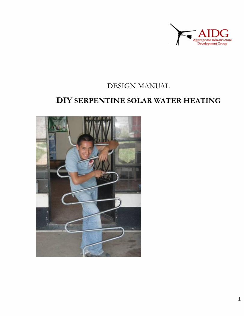
DESIGN MANUAL
DIY SERPENTINE SOLAR WATER HEATING
2
1 Abstract ...................................................................................................................................... 5
2. Introduction ............................................................................................................................... 6
2.1 Project Objectives ............................................................................................................... 6
2.2 Local Climatic Conditions .................................................................................................... 7
3. Need Identification .................................................................................................................... 8
3.1 User Constraints: Affordability ............................................................................................. 8
3.2 Solar Energy in Guatemala: General Benefits ..................................................................... 8
3.3 Urban Xela: Water Heating and Shower Habits................................................................... 9
3.4 Electricity Consumption Trends: Guatemala........................................................................ 9
3.5 Daily Domestic Water Heating Demand: Urban Xela .......................................................... 9
3.6 Projected Financial Savings ................................................................................................ 9
4. Quantified Engineering Requirements .................................................................................... 11
4.1 Thermal Requirement ........................................................................................................ 11
4.2 Collector area .................................................................................................................... 11
5 Evaluation Procedure ............................................................................................................... 12
5.1 Performance ...................................................................................................................... 12
5.2 Cost ................................................................................................................................... 12
5.3 Durability ........................................................................................................................... 12
5.4 Local Availability of Materials ............................................................................................. 12
5.5 Safety ................................................................................................................................ 12
6. Conceptual Designs ................................................................................................................ 13
6.0 Design Selection ............................................................................................................... 13
6.1 Thermo-siphon .................................................................................................................. 14
6.2 Direct Heat Exchange ....................................................................................................... 14
6.3 Frost Protection ................................................................................................................. 14
6.4 Solar Collector ................................................................................................................... 14
6.5 Hot Water Storage Tank .................................................................................................... 15
7. Final Design Selection. Comparison of feasible options ......................................................... 15
7.1 Serpentine Collectors ........................................................................................................ 15
7.1.1 Absorber pipe-work: Gal. iron vs. Copper. .................................................................. 15
7.1.2 Absorber pipe-work: Serpentine vs. Grid .................................................................... 15
7.1.3 Panel backing and framing ......................................................................................... 16
7.1.4 Glass vs. Acrylic cover ................................................................................................ 16
7.1.5 Sealing/ clamping ....................................................................................................... 16
7.2 Hot Water tanks ................................................................................................................. 16
7.2.1 Sealed Tanks .............................................................................................................. 16
7.2.2 Procuring commercially manufactured hot water tanks ............................................... 16
7.3 Solar Circuit ....................................................................................................................... 17

3
7.3.1 Anti-return valve .......................................................................................................... 17
7.3.2 Poliducto/ PVC ............................................................................................................ 17
8. Detailed Design ....................................................................................................................... 18
8.1 System Sizing (i) ............................................................................................................... 18
8.1.1. System Efficiency: ...................................................................................................... 18
8.2 System Sizing (ii) ............................................................................................................... 21
8.3 Design: Solar Collector ...................................................................................................... 21
8.3.1 Absorber .............................................................................................................. 21
8.3.2 Absorber Frame ................................................................................................... 22
8.3.3 Cover ................................................................................................................... 23
8.3.4 Insulation ............................................................................................................. 23
8.3.5 Clamps ................................................................................................................ 23
8.4 Design: Hot water Tank ..................................................................................................... 23
8.4.1 Insulation .................................................................................................................... 24
8.4.7 Weather proofing ........................................................................................................ 26
9 Further Work ............................................................................................................................ 27
9.1 Selective-Absorber Layer for the Collector. ....................................................................... 27
9.2 Increasing Collector Surface Area ..................................................................................... 27
9.3 Copper: Protection against high-temperatures .................................................................. 27
9.4 Collector „Clip Fins‟ ............................................................................................................ 28
9.5 Hot Water Tank: Sacrificial Anode ..................................................................................... 28
9.6 Increased Hot Water Tank and Collector Insulation. Heat Loss Coefficients. ................. 28
9.7 Aerator ........................................................................................................................... 29
9.8 Night time Heat Loss from Tank Inlet ............................................................................. 29
9.9 Inverted Return to the Collectors ....................................................................................... 29
9.10 Efficiency Coefficients .................................................................................................. 30
9.11 Horizontal tanks ........................................................................................................... 30
10. Material Costs in Guatemala ................................................................................................. 31
11 Conclusions ............................................................................................................................ 32
Appendix 1 Risk of Legionnaires Disease ................................................................................... 33
Appendix 2 Existing Installation Case Studies ............................................................................ 33
A2.1 Nueva Alianza Hotel ........................................................................................................ 33
A2.2 Entre-Mundos ................................................................................................................ 34
A2.2.2 Update 2010 ................................................................................................................ 35
A2.3 La Guarderia, Llanos del Pinal ........................................................................................ 35
4
Notes and Glossary: All measurements in the text are in mm unless otherwise shown. Measurements describing the positions of holes for bolts or inlet pipes etc are taken to the centre of the hole unless other-wise stated. Xela –Quetzaltenango AIDG –Appropriate Infrastructure Development Group. Xelateco – A renewable energy manufacture/ installation business set up by AIDG Guatemala Azimuth: Orientation from due South 0º. SSWH – Serpentine Solar Water Heating SWH – Solar Water Heating HG “Hierro Galvanizado”: Galvanized Pipe MDF Medium Density Fibreboard NPT: National Pipe Threading. American pipe gauge standards: http://www.engineeringtoolbox.com/npt-national-pipe-taper-threads-d_750.html °C – Degrees centigrade
References CalSolAgua Team (2007). Domestic Solar Water Heater for Developing Countries Berkley Uni Energy & Resources Group ER 291-3 CalSolAgua Team (2008). November 2009 Survey Write Up Berkley Uni Energy & Resources Group ER 291-3 B. Deus et al (2004) : ZigZag Collector, BABICO and WOT Publications B. Dana (2009): Serpentine Solar Water Heating, Guidelines for Manufacture AIDG Revision Date Author B – FinalDraft November 2009 Ben Dana [email protected]

5
1 Abstract
The Serpentine is a solar thermal collector developed as part of a low cost water heating system by the AIDG for households in Xela, Guatemala. This document outlines general design principles: thermo-siphon and direct heat exchange. Alternative solar thermal designs are evaluated and an explanation is given for our selection. The AIDG document Serpentine Solar Water Heating: Guidelines for Manufacture gives a comprehensive list of system component materials, together with detailed accounts of solar collector and hot water tank fabrication. This Design Manual provides guidance on system sizing and system efficiency estimates based on test performance. Technical refinements are ongoing in order to improve performance and safety while minimizing costs. Several modifications are recommended for future research, including:
Increasing absorber area
Improved collector sealing.
The addition of a Sacrifial Anode in the tank for corrosion protection
Increasing tank insulation and insulating pipe-work
Improving the roof-mounting structures.
Inclusion of the Inverted Return Pipe.

6
.
2. Introduction
2.1 Project Objectives
The success of the Serpentine Solar Water Heaters is based on the following criteria:
Ability to cater to domestic water heating requirements in Xela and surrounding towns
Affordability for regional households
Use of locally available materials for fabrication in the region. AIDG strives to stimulate local business and employment.
Durability over a long life-time; the product should be a viable financial investment
Minimization of Health and Safety risks.
The development of a product meeting these objectives will generate the potential for reduced use of In-line electric showers. Environmental benefits to follow include reduced stress on the Guatemalan electrical grid infrastructure; improved air quality; and Carbon Dioxide emissions reductions1.
1 According to a lifecycle analysis conducted in Australia, domestic solar water heating systems can
produce net greenhouse gas savings in 2.5 – 5 years Building Research and Information (2003) 31:34-47.

7
2.2 Local Climatic Conditions
There are two main seasons in Xela; the rainy season is May through November and the dry season is December to May. At 2333m in elevation, Xela is located within a mountain valley. Ambient temperatures typically range from15-25°C during the day and 4-10°C at night, although temperatures have dropped as low as -6°C at night, and can exceed 25°C in summer. Low temperatures at night create a design challenge in developing an affordable system which caters for early morning showers. Extra tank insulation is expensive. However, as shown by the table below the area benefits from strong solar irradiation throughout the year.
NREL CSR Solar Model Output, Cell ID =
0
1000
2000
3000
4000
5000
6000
7000
8000
Jan Feb Mar Apr May Jun Jul Aug Sep Oct Nov Dec
Month
Irra
dia
nce W
att
-Ho
urs
/M2/D
ay
Direct
Global
Latitude Tilt
Diffuse
Graph 1: Solar irradiance, Guatemalan W. Highlands (location of Xela.)
Notes: graph 1 is downloaded from http://swera.unep.net/index.php?id=35&idx=339. The following notes are given
1. Global Horizontal is the sum of direct and diffuse incident on a horizontal surface. The direct incident is the direct normal times the cosine of the zenith angle (angle between straight overhead and the sun.) So early morning and late afternoon, the direct incident will be much less than the direct normal.
2. Direct Normal is the radiation available to a concentrating mirror that tracks the sun. There is no cosine relationship, the incidence angle is assumed to be 0 at all times. So for sufficiently clear time periods, Direct Normal Irradiance (DNI) can be more than Global Horizontal Irradiance.
3. Also, DNI is easily blocked by clouds and aerosols (haze and dust). If it is somewhat cloudier in April than it is in January, you could easily have more DNI in January.
4. Latitude tilt is the optimum angle to get the most total global radiation for the entire year. However, in the summer it often is the case that horizontal is closer to the average sun angle than latitude tilt.
The data is used for system sizing; we assume minimum solar irradiance/ per day is consistently above 5kWh/ m².
8
3. Need Identification
3.1 User Constraints: Affordability
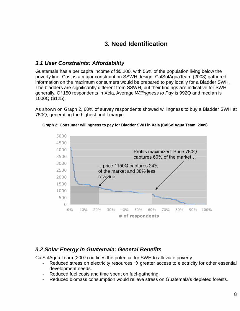
Guatemala has a per capita income of $5,200, with 56% of the population living below the poverty line. Cost is a major constraint on SSWH design. CalSolAguaTeam (2008) gathered information on the maximum consumers would be prepared to pay locally for a Bladder SWH. The bladders are significantly different from SSWH, but their findings are indicative for SWH generally. Of 150 respondents in Xela, Average Willingness to Pay is 992Q and median is 1000Q ($125). As shown on Graph 2, 60% of survey respondents showed willingness to buy a Bladder SWH at 750Q, generating the highest profit margin.
Graph 2: Consumer willingness to pay for Bladder SWH in Xela (CalSolAgua Team, 2009)
3.2 Solar Energy in Guatemala: General Benefits
CalSolAgua Team (2007) outlines the potential for SWH to alleviate poverty: - Reduced stress on electricity resources greater access to electricity for other essential
development needs. - Reduced fuel costs and time spent on fuel-gathering. - Reduced biomass consumption would relieve stress on Guatemala‟s depleted forests.
0
500
1000
1500
2000
2500
3000
3500
4000
4500
5000
0% 10% 20% 30% 40% 50% 60% 70% 80% 90% 100%
# of respondents
Willin
gn
ess t
o P
ay (
Q)
Profits maximized: Price 750Q captures 60% of the market…
…price 1150Q captures 24% of the market and 38% less revenue
9
- Reduced exposure to toxins and pollutants released from burning biomass fuels. However in rural areas reliant on biomass, water heating for showers is generally uncommon; this could limit consumer demand for SWH even at low costs.
3.3 Urban Xela: Water Heating and Shower Habits
The market for SWH is most likely to be found in the city itself and surrounding towns. Daily showering in households in Xela typically takes place early in the morning (between 5am and 8am.) The water plumbing in households is only for cold water. To heat water, families use an in-line electrical showerhead heater that is expensive to use due to the high cost of electricity. Households often have a limited electrical power supply (there are frequent power outages).
3.4 Electricity Consumption Trends: Guatemala
The benefits of reducing electrical showers are underlined by general trends. Between 1985 and 2000, total growth in electricity consumption (224%) far exceeded population growth (41%) and GDP growth (138%).1 Electricity needs are expected to increase for the foreseeable future, as Guatemala seeks to increase its standard of living and develop its economy. Growing electricity needs will force the country to become more reliant on carbon-emitting fuel sources and fuel imports, exposing it to price fluctuations in international energy markets.
3.5 Daily Domestic Water Heating Demand: Urban Xela
CalSolAgua Team estimate that three showers per day to be the norm in a typical household, with an average shower time of 7.5 minutes. This will vary obviously, with bigger families taking more showers. However optimal system design requires a balance between enhanced performance and affordability. The same group found that gravity fed showers in Guatemala can reach up to 0.06l/ second flow, in which case 27l of heated water would be required for a shower. A 100l tank is selected therefore.
3.6 Projected Financial Savings
A SSWH system with three Collectors in Xela could produce an annual energy cost savings of $41 (see Table 2). Electricity costs are higher in other parts of the country, where it‟s estimated annual savings would be as high as $115. This estimate is based on power usage for a household that takes 3 showers per day. Currently, most households rely on in-line electric shower heaters, which typically require 6 kW of power. As shown in 8.1 a three collector system could save up to 80% of electrical showering costs, representing 660kWh.
1 (paragraph Electricity Consumption Trends: Guatemala) Globalis. Global Virtual University,
http://globalis.gvu.unu.edu accessed Sept. 19, 2007.
10
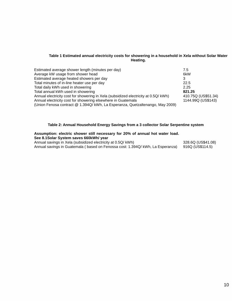
Table 1 Estimated annual electricity costs for showering in a household in Xela without Solar Water Heating.
Estimated average shower length (minutes per day) 7.5 Average kW usage from shower head 6kW Estimated average heated showers per day 3 Total minutes of in-line heater use per day 22.5 Total daily kWh used in showering 2.25 Total annual kWh used in showering 821.25 Annual electricity cost for showering in Xela (subsidized electricity at 0.5Q/ kWh) 410.75Q (US$51.34) Annual electricity cost for showering elsewhere in Guatemala (Union Fenosa contract @ 1.394Q/ kWh, La Esperanza, Quetzaltenango, May 2009)
1144.99Q (US$143)
Table 2: Annual Household Energy Savings from a 3 collector Solar Serpentine system
Assumption: electric shower still necessary for 20% of annual hot water load. See 8.1Solar System saves 660kWh/ year
Annual savings in Xela (subsidized electricity at 0.5Q/ kWh) 328.6Q (US$41.08) Annual savings in Guatemala ( based on Fenossa cost: 1.394Q/ kWh, La Esperanza) 916Q (US$114.5)
11
4. Quantified Engineering Requirements
4.1 Thermal Requirement
The daily requirement is 100l of water heated to 35ºC. 10ºC is assumed to be the starting temperature from the mains supply. This represents 3-4 showers. Energy required for water heating (kcal) = Volume x temperature difference x specific heat capacity of water 100l x 25ºC x 1kcal/ L/ ºC
2500 kCal This represents 2.91kWh1
4.2 Collector area
Solar Collector area required to meet this requirement =
Energy requirement for Water Heating Available Solar Energy/ m² x Collector Efficiency
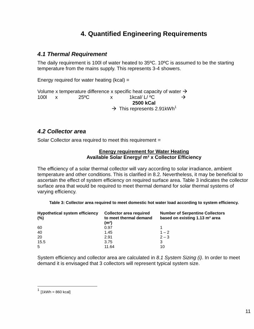
The efficiency of a solar thermal collector will vary according to solar irradiance, ambient temperature and other conditions. This is clarified in 8.2. Nevertheless, it may be beneficial to ascertain the effect of system efficiency on required surface area. Table 3 indicates the collector surface area that would be required to meet thermal demand for solar thermal systems of varying efficiency.
Table 3: Collector area required to meet domestic hot water load according to system efficiency.
Hypothetical system efficiency (%)
Collector area required to meet thermal demand (m²)
Number of Serpentine Collectors based on existing 1.13 m² area
60 0.97 1 40 1.45 1 – 2 20 2.91 2 – 3 15.5 3.75 3 5 11.64 10
System efficiency and collector area are calculated in 8.1 System Sizing (i). In order to meet demand it is envisaged that 3 collectors will represent typical system size.
1 [1kWh = 860 kcal]

12
5 Evaluation Procedure
The SSWH criteria for technological success are prioritized according to a market survey of 150 people in Xela on „Bladder‟ solar heaters conducted by CalSolAgua Team (2009). Although the „Bladders‟ are significantly different from the Serpentines the information is indicative for SWH generally.
5.1 Performance
Energy Saving was the most important issue, 83% of participants deeming this to be a very attractive feature, and 16% to be an attractive feature of the water heaters. Only 48% indicated interest in purchasing a system that wouldn‟t replace their existing water heater (it‟s estimated that electrical heating will be necessary for at least 20% of the year.) As concerns about the bladder, Timing of the hot water was listed as a Major Problem by 59% and as a problem by 31%. 58.6% were concerned about Not Enough Hot Water, counting this as a Major Problem. A further 31% of participants deemed it to be a Problem However 61% of participants expressed interest in purchasing a system even if hot water was only available during the day. This suggests a local willingness to change showering routine to make the most of SWH.
5.2 Cost
Only 18% of respondents listed Cost as the most important feature of a Solar Water Heating System; Performance was listed by 53%. However, limiting costs to 750Q would capture 60% of the market according to this survey. A focus group conducted as part of the same market research suggested that consumers would hope for a payback time of one year.
5.3 Durability
As a concern, bladder Durability was listed as Major Problem by 51% of survey correspondents, and as a Problem by 41%, making it a significant issue.
5.4 Local Availability of Materials
This issue was not raised in the survey. Relating to local business incubation, consumers may not see the relevance. However for AIDG it ranks highly, as business incubation is central to its agenda. The issue has a significant effect on cost.
5.5 Safety
Using SWH reduces electric shock risk in Guatemala. However, only 27% of participants list Safety Benefit as a Very Attractive system feature; Attractive for 54%. It‟s a lower priority than Performance and Cost. This indicates that consumers would not see hazard reduction in the SWH system itself of as worthy of extra costs. Nevertheless, safety is an essential consideration in designing the Serpentine system and shouldn‟t be compromised.
13
6. Conceptual Designs
6.0 Design Selection
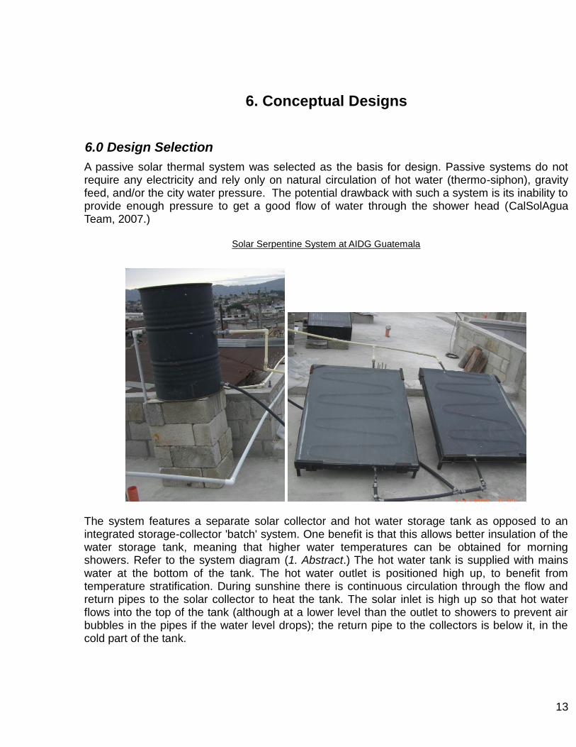
A passive solar thermal system was selected as the basis for design. Passive systems do not require any electricity and rely only on natural circulation of hot water (thermo-siphon), gravity feed, and/or the city water pressure. The potential drawback with such a system is its inability to provide enough pressure to get a good flow of water through the shower head (CalSolAgua Team, 2007.)
Solar Serpentine System at AIDG Guatemala
The system features a separate solar collector and hot water storage tank as opposed to an integrated storage-collector 'batch' system. One benefit is that this allows better insulation of the water storage tank, meaning that higher water temperatures can be obtained for morning showers. Refer to the system diagram (1. Abstract.) The hot water tank is supplied with mains water at the bottom of the tank. The hot water outlet is positioned high up, to benefit from temperature stratification. During sunshine there is continuous circulation through the flow and return pipes to the solar collector to heat the tank. The solar inlet is high up so that hot water flows into the top of the tank (although at a lower level than the outlet to showers to prevent air bubbles in the pipes if the water level drops); the return pipe to the collectors is below it, in the cold part of the tank.
14
6.1 Thermo-siphon
Circulation from the solar collector(s) to the hot water tank through thermo-siphon requires the tank to be situated above the collectors. The motive force for fluid circulation is the density difference between the collector inlet and outlet caused by heating. A gradient is necessary in the flow to the cylinder. Positioning this pipe with an upwards gradient will make thermo-siphon possible even if the collector and cylinder are at the same height. Positioning the tank above the collectors complicates installation on a pitched roof; on a flat roof it only requires provision of a sufficiently high base for the tank to be mounted on. Circulation also relies an upwards pipe gradient in the collectors themselves.
6.2 Direct Heat Exchange
The flow and return pipes between the solar collector and the tank do not constitute a closed circuit, as the fluid circulating is not separated from the water which is being heated for use. A closed 'Solar circuit' or 'Primary circuit' would require the tank to feature a heat exchanger, increasing costs. It would also need to feature a pressure release valve and an expansion vessel.
6.3 Frost Protection
This 'direct' system means that frost protection measures can not be featured. In a closed Primary circuit anti-freeze such as glycol would often be the fluid used for heat exchange, to prevent leaks caused by the expansion of freezing water. In the case of the SSWH, glycol would contaminate Domestic Hot Water and quickly reduce its concentration. However AIDG regards the risk posed by freezing in Xela, Guatemala as being low. Temperatures may drop below 0°C for up to four hours on Winter nights, but this is followed by warm day-time temperatures; it's thought that freezing conditions are not sustained long enough for damaged pipe-work to be an issue. However if this technology is used elsewhere the world, the risks of frost damage in a particular region should be assessed; if necessary the system should be modified to feature frost protection. The most basic measure would be a drain-cock at the lowest point of return pipe to the collectors, to drain the system before freezing conditions. However this requires vigilance and safe roof access.
6.4 Solar Collector
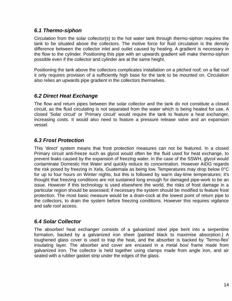
The absorber/ heat exchanger consists of a galvanized steel pipe bent into a serpentine formation, backed by a galvanized iron sheet (painted black to maximise absorption.) A toughened glass cover is used to trap the heat, and the absorber is backed by 'Termo-flex' insulating layer. The absorber and cover are encased in a metal box/ frame made from galvanized iron. The collector is held together using clamps made from angle iron, and air sealed with a rubber gasket strip under the edges of the glass.
15
6.5 Hot Water Storage Tank
Earlier prototype tanks had a metal inner tank as well as a metal outer casing. However corrosion over the years can lead to leaks, especially if there is no sacrificial anode. The current design features a plastic barrel for the inner tank (more information on the maximum safe temperatures of the plastic and how many collectors should be connected would be beneficial.) The tank is vented to prevent damage to the tank and fittings by excessive pressure and temperature build-up. A float valve cuts off the mains water supply to the tank when the maximum level is reached. This has the disadvantages of allowing heat loss through evaporation (via the air space above the ball valve), and meaning that water flow at the point of use (shower) will be poor if the pressure drop (difference in height) from the hot water tank is low. However overcoming these problems with a pressurized tank would add costs.
7. Final Design Selection. Comparison of feasible options
7.1 Serpentine Collectors
7.1.1 Absorber pipe-work: Gal. iron vs. Copper.
Prototype absorbers were built using copper for the serpentine rather than gal. iron. As copper has a high thermal conductivity, this was attempted in order to improve heat exchange. It was hoped that improving efficiency could allow collector surface area to be reduced, reducing costs. However, side by side collector testing showed only marginal temperature gains over the existing serpentine material. This may be partly due to the low thermal conductivity of the Gal. Laminar backing plate. There were practical problems as well as extra expense:
Large diameter copper (for increased flow) can be brittle therefore making the serpentine difficult to manufacture. In Guatemala it is difficult to source flexible copper which is larger than 3/8”.
Currently the pipe is attached to the absorber plate using wire. However welding copper to gal. iron, for better contact, would require welding sticks which are not available in Guatemala.
7.1.2 Absorber pipe-work: Serpentine vs. Grid
Little testing has been carried out with grid-pipe-work absorbers. One benefit of the Serpentine is the avoidance of joints in the collector itself. With a pipe-grid absorber soft-soldered joints (in the case of copper) might not withstand elevated temperatures in the collector; braising the joints would be a more specialized skill and adds expense. A grid made from Gal. iron pipe would either require specialized welding, or expensive threaded joints (again Teflon may not withstand collector temperature.) A grid would also be more time consuming to make than a serpentine. Nevertheless, a prototype grid-pipe-work absorber was built, with large diameter copper for the header and footer (for flow) and small diameter for the runners (for surface area to water ratio). The difficulty of construction was, as expected, high. The absorber was never tested on a collector because of leaks in the soldered joints.
16
7.1.3 Panel backing and framing
Earlier versions of the SSWH used backing made from Medium Density Fiberboard. This was found to absorb water (rain ingress etc.), causing swelling. Plywood and thin plastic were tried (or considered) before the development of the current design which uses Gal. Laminar for backing. In the past frames were also made from wood. However the current use of galvanized rail/ channel for the sides improves the collector‟s weather proofing and durability and a longer lifetime can be expected.
7.1.4 Glass vs. Acrylic cover
Transparent acrylic is available in Xela (Central Minera.) It was used as a collector cover in early prototypes to avoid the problem of glass breakage. It is similar in cost, but after a year loses its transparency, inhibiting solar gain.
7.1.5 Sealing/ clamping
Previously silicone was used to prevent air loss around the edges of the glass cover. However, this made it difficult to remove the glass for maintenance, leading to breakages. Unless high-temperature resistant silicone is used it is also liable to degrade. As a result the current system of brackets was developed to sandwich the collector layers together. For air tightness a rubber gasket strip is used to line the edge of the frame underneath the glass. However air gaps are still noticeable on some installations. One possible solution would be to fold the rubber gasket round the edge of the glass, and held in place under the bracket on top.
7.2 Hot Water tanks
7.2.1 Sealed Tanks
Use of a sealed/ pressurized hot water cylinder would enable hot water to be supplied at mains pressure to the showers; currently hot water supply relies on gravitational feed, reducing flow. Efficiency would also be improved by removing the need for a float valve; the air space above it currently allows hot water to evaporate and escape through the vented lid. However this would increase project costs. As well as a Pressure Release Valve and Expansion Vessel, a commercially manufactured pressurized tank may be necessary.
7.2.2 Procuring commercially manufactured hot water tanks
If these are locally available there would be the advantage of saving time and labour and providing a purpose built durable tank with corrosion-protection. The size could be selected to match system demands. However costs would be likely to mean that this would not be an option for the low-income market intended for SSWH. Tanks may only be available with a single inlet and outlet, meaning that they would have to be re-engineered to accommodate the flow and return to the collectors. Insulation may also need to be added.

17
7.3 Solar Circuit
7.3.1 Anti-return valve
An anti-return or “check valve” is usually a feature of pumped systems to prevent overnight heat loss from the tank due to „reverse thermo-siphon‟. This is when colder solar fluid flows from the collectors on the roof to the tank which is at a higher temperature.
Reverse flow should be eliminated if the tip of the collector is below the bottom fitting of the tank. Therefore it is felt that this valve can be avoided in a SSWH system. For thermo-siphon applications where there is little or no difference in level between the collector and inlet to the tank, a check valve is required to prevent backflow.
However conventional types of check-valves used in active/pumped systems would be likely to restrict thermo-siphon. In the absence of the right type of check valve, a shut off valve could be installed; either on the flow or the return depending on where height difference is the problem. It should be closed in the evening and opened first thing in the morning manually, meaning this measure may be impossible if roof access is poor. Monitoring will be necessary to ascertain whether it restricts the thermo-siphon.
7.3.2 Poliducto/ PVC
In April 2009 a test installation was carried out on the house of AIDG Interns. Poliducto (black pipe used for irrigation etc.) were used for the flow and return pipes to the solar collectors. This is not recommendable; pipes and fittings which are rated to withstand high temperatures are to be specified. However it is mentioned because of the ease of connection to different fittings: ¾” poliducto fits over ½” gal serpentine pipe snugly so that joins are carried out with plenty of PTFE tape and one or more jubilee clips fully tightened on the outside. In section 9, Further Work, design changes are proposed for future testing.
18
8. Detailed Design
8.1 System Sizing (i)
As shown in (4) Quantified Engineering Requirements, typical household thermal demand is calculated as 2.91kWh. Solar Collector area required to meet this requirement =
Energy requirement for Water Heating Available Solar Energy/ m² x Collector Efficiency
Available Solar Energy Global Solar Irradiation at the geographical location can be used, or irradiation on a tilted plane. Graph 1 (2.2 Local Climatic Conditions) represents solar irradiation data for Xela. Global solar irradiation per day at latitude tilt is consistently above 5kWh/ m².This minimum value is used for system sizing to enable the system to meet requirements for water heating during winter months.
8.1.1. System Efficiency:
To simplify matters SSWH system efficiency is taken to be:
System output (based on temperature rise in the tank) % Solar Irradiation
8.1.1.1 System Output:
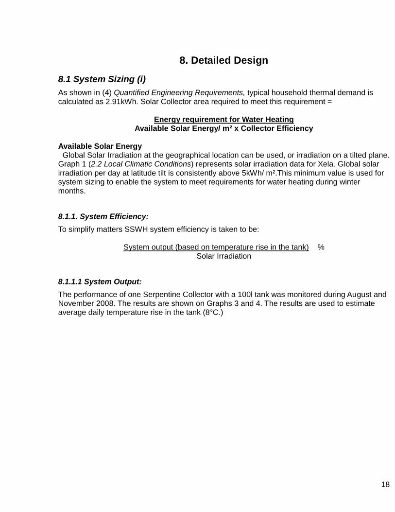
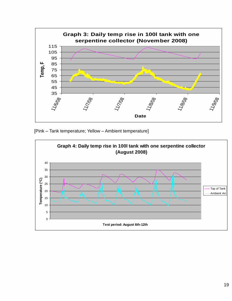
The performance of one Serpentine Collector with a 100l tank was monitored during August and November 2008. The results are shown on Graphs 3 and 4. The results are used to estimate average daily temperature rise in the tank (8°C.)
19
Graph 3: Daily temp rise in 100l tank with one
serpentine collector (November 2008)
35
45
55
65
75
85
95
105
115
11/6
/08
11/7
/08
11/7
/08
11/8
/08
11/8
/08
11/9
/08
Date
Tem
p, F
[Pink – Tank temperature; Yellow – Ambient temperature]
Graph 4: Daily temp rise in 100l tank with one serpentine collector
(August 2008)
0
5
10
15
20
25
30
35
40
Test period: August 6th-12th
Tem
pera
ture
(°C
)
Top of Tank
Ambient Air
20
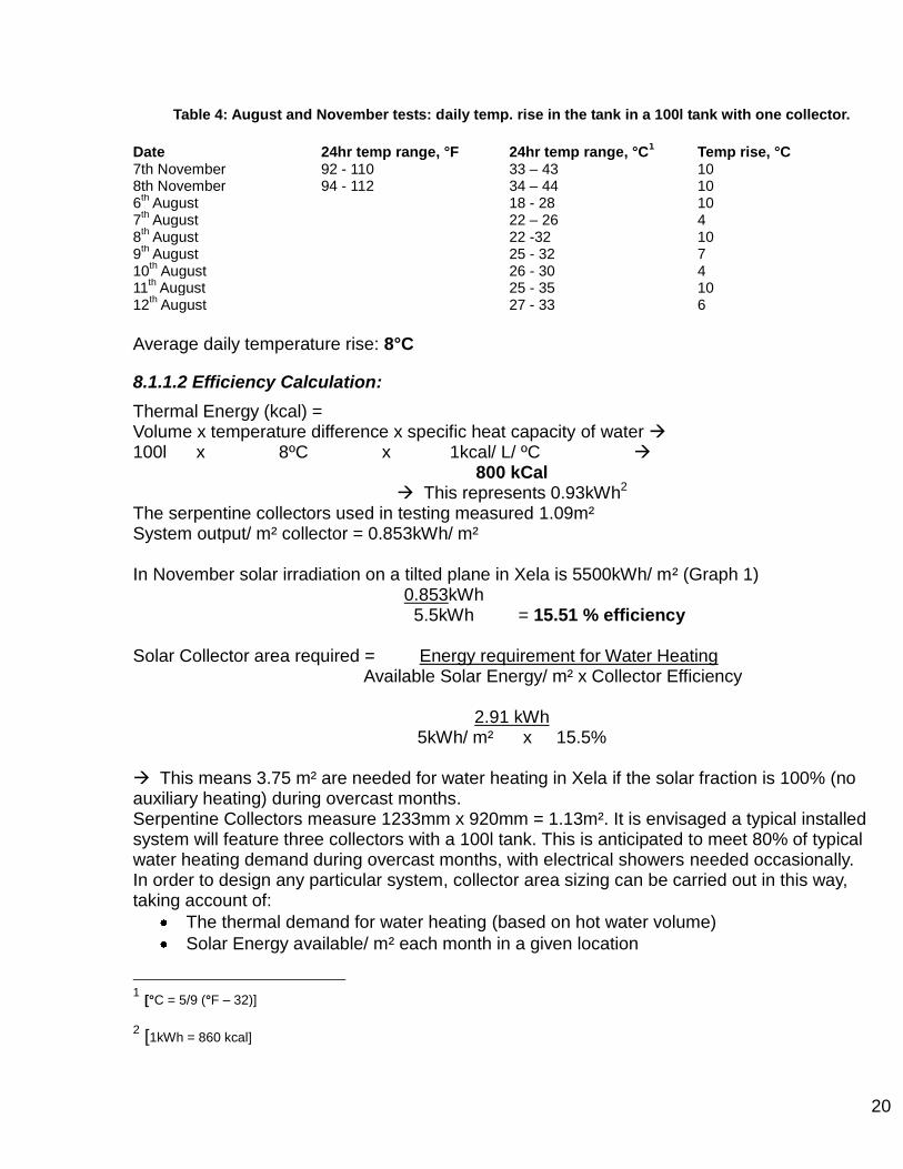
Table 4: August and November tests: daily temp. rise in the tank in a 100l tank with one collector.
Date 24hr temp range, °F 24hr temp range, °C
1 Temp rise, °C
7th November 92 - 110 33 – 43 10 8th November 94 - 112 34 – 44 10 6
th August 18 - 28 10
7th August 22 – 26 4
8th August 22 -32 10
9th August 25 - 32 7
10th August 26 - 30 4
11th August 25 - 35 10
12th August 27 - 33 6
Average daily temperature rise: 8°C
8.1.1.2 Efficiency Calculation:
Thermal Energy (kcal) = Volume x temperature difference x specific heat capacity of water 100l x 8ºC x 1kcal/ L/ ºC
800 kCal This represents 0.93kWh2
The serpentine collectors used in testing measured 1.09m² System output/ m² collector = 0.853kWh/ m² In November solar irradiation on a tilted plane in Xela is 5500kWh/ m² (Graph 1) 0.853kWh 5.5kWh = 15.51 % efficiency
Solar Collector area required = Energy requirement for Water Heating Available Solar Energy/ m² x Collector Efficiency
2.91 kWh
5kWh/ m² x 15.5%
This means 3.75 m² are needed for water heating in Xela if the solar fraction is 100% (no auxiliary heating) during overcast months. Serpentine Collectors measure 1233mm x 920mm = 1.13m². It is envisaged a typical installed system will feature three collectors with a 100l tank. This is anticipated to meet 80% of typical water heating demand during overcast months, with electrical showers needed occasionally. In order to design any particular system, collector area sizing can be carried out in this way, taking account of:
The thermal demand for water heating (based on hot water volume)
Solar Energy available/ m² each month in a given location
1 [°C = 5/9 (°F – 32)] 2 [1kWh = 860 kcal]
21
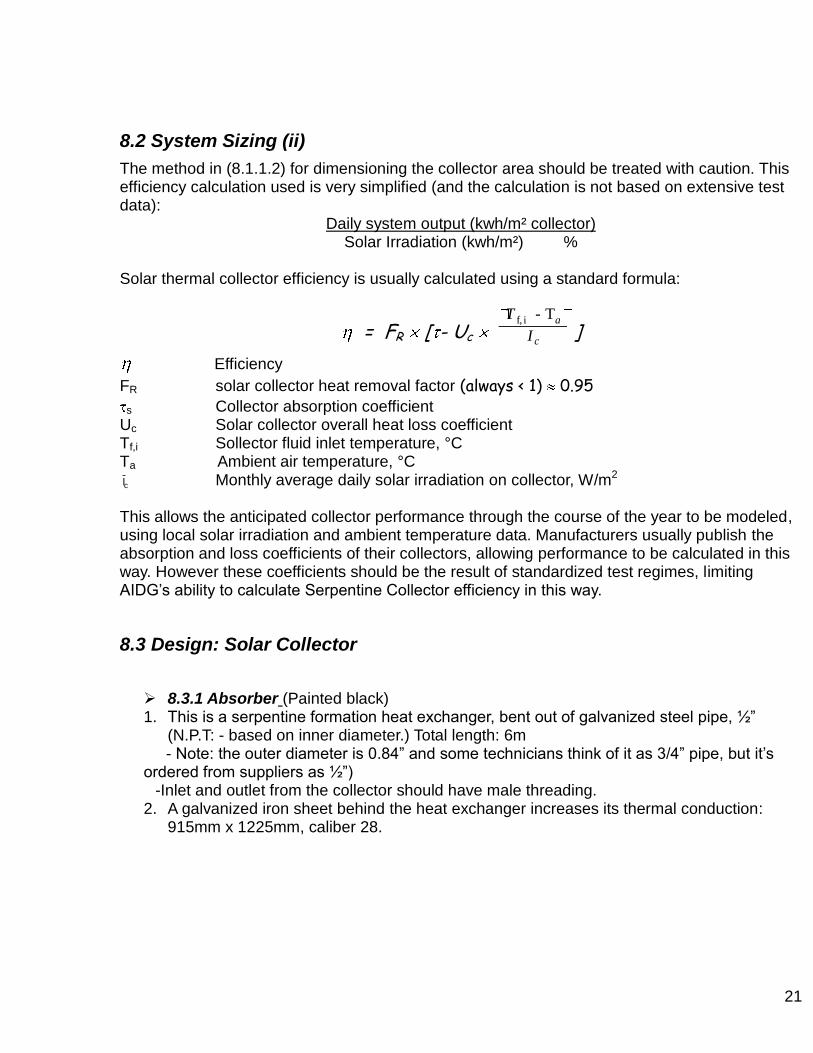
8.2 System Sizing (ii)
The method in (8.1.1.2) for dimensioning the collector area should be treated with caution. This efficiency calculation used is very simplified (and the calculation is not based on extensive test data):
Daily system output (kwh/m² collector) Solar Irradiation (kwh/m²) %
Solar thermal collector efficiency is usually calculated using a standard formula:
= FR [ - Uc T f, i - Ta
I c]
Efficiency
FR solar collector heat removal factor (always < 1) 0.95
s Collector absorption coefficient Uc Solar collector overall heat loss coefficient Tf,i Sollector fluid inlet temperature, °C Ta Ambient air temperature, °C
cI Monthly average daily solar irradiation on collector, W/m2
This allows the anticipated collector performance through the course of the year to be modeled, using local solar irradiation and ambient temperature data. Manufacturers usually publish the absorption and loss coefficients of their collectors, allowing performance to be calculated in this way. However these coefficients should be the result of standardized test regimes, limiting AIDG‟s ability to calculate Serpentine Collector efficiency in this way.
8.3 Design: Solar Collector
8.3.1 Absorber (Painted black) 1. This is a serpentine formation heat exchanger, bent out of galvanized steel pipe, ½”
(N.P.T: - based on inner diameter.) Total length: 6m - Note: the outer diameter is 0.84” and some technicians think of it as 3/4” pipe, but it‟s ordered from suppliers as ½”)
-Inlet and outlet from the collector should have male threading. 2. A galvanized iron sheet behind the heat exchanger increases its thermal conduction:
915mm x 1225mm, caliber 28.
22
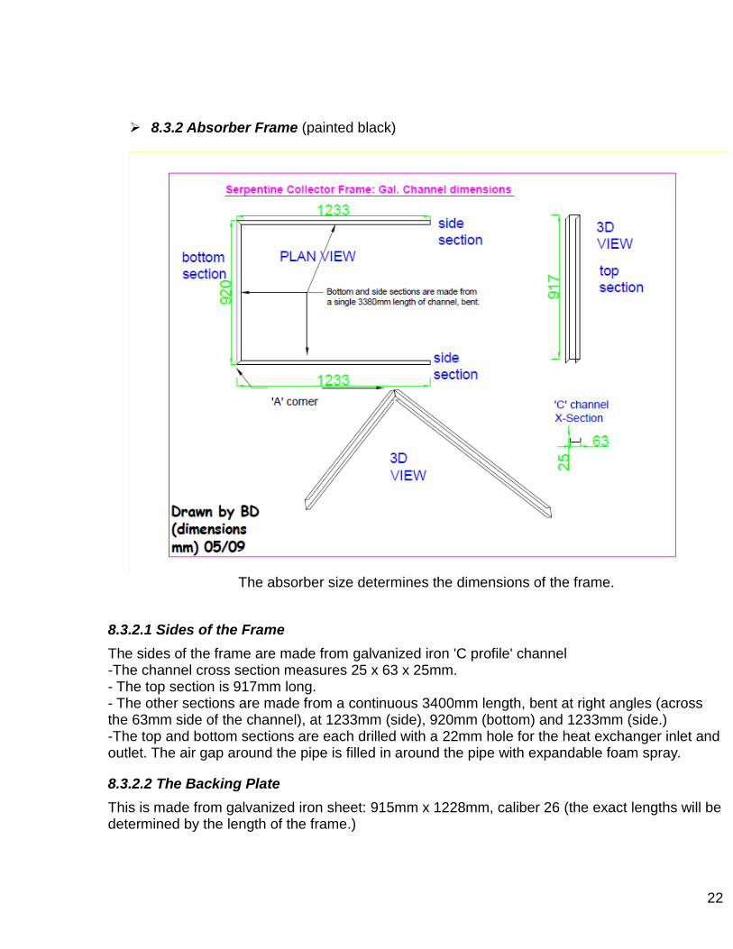
8.3.2 Absorber Frame (painted black)
The absorber size determines the dimensions of the frame.
8.3.2.1 Sides of the Frame
The sides of the frame are made from galvanized iron 'C profile' channel -The channel cross section measures 25 x 63 x 25mm. - The top section is 917mm long. - The other sections are made from a continuous 3400mm length, bent at right angles (across the 63mm side of the channel), at 1233mm (side), 920mm (bottom) and 1233mm (side.) -The top and bottom sections are each drilled with a 22mm hole for the heat exchanger inlet and outlet. The air gap around the pipe is filled in around the pipe with expandable foam spray.
8.3.2.2 The Backing Plate
This is made from galvanized iron sheet: 915mm x 1228mm, caliber 26 (the exact lengths will be determined by the length of the frame.)
23
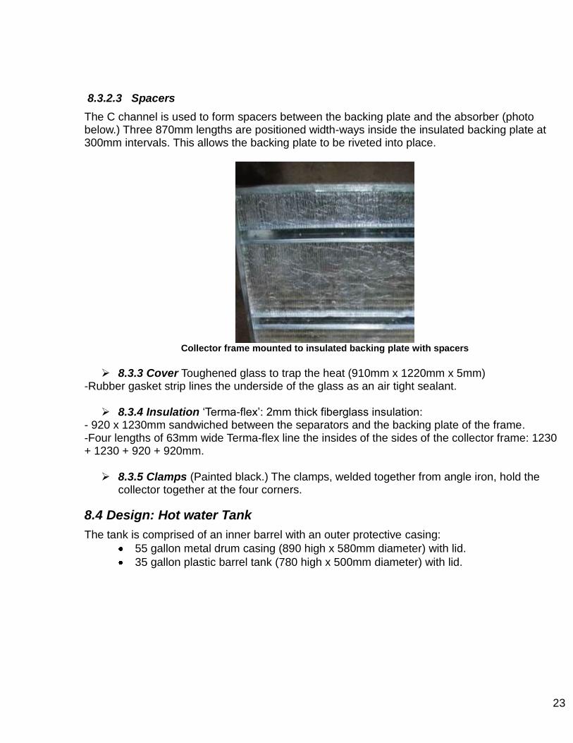
8.3.2.3 Spacers
The C channel is used to form spacers between the backing plate and the absorber (photo below.) Three 870mm lengths are positioned width-ways inside the insulated backing plate at 300mm intervals. This allows the backing plate to be riveted into place.
Collector frame mounted to insulated backing plate with spacers
8.3.3 Cover Toughened glass to trap the heat (910mm x 1220mm x 5mm)
-Rubber gasket strip lines the underside of the glass as an air tight sealant. 8.3.4 Insulation „Terma-flex‟: 2mm thick fiberglass insulation:
- 920 x 1230mm sandwiched between the separators and the backing plate of the frame. -Four lengths of 63mm wide Terma-flex line the insides of the sides of the collector frame: 1230 + 1230 + 920 + 920mm. 8.3.5 Clamps (Painted black.) The clamps, welded together from angle iron, hold the
collector together at the four corners.
8.4 Design: Hot water Tank
The tank is comprised of an inner barrel with an outer protective casing:
55 gallon metal drum casing (890 high x 580mm diameter) with lid.
35 gallon plastic barrel tank (780 high x 500mm diameter) with lid.

24
Inner hot water tank
The tank is vented for pressure release. The lid of the Inner Barrel is not air tight.
8.4.1 Insulation
Two rolls of 2mm fiberglass Termo-flex insulation (approx 1800 wide x 900mm high each) are wrapped around the inner-tank and one inside the outer drum. A cylindrical piece of polystyrene foam is used to cover the inner tank lid for extra insulation: approximately 25mm thick x 56mm diameter. 8.4.2 Inner tank hole positions for inlets1: (bottom of the tank‟s inside to hole centre)
Cold water feed – 100mm
Hot water out – 540mm
Solar Flow (hot) – 460mm
Solar Return (below it) - 95mm. 8.4.4 Outer tank hole positions for inlets: (from floor outside the tank to hole centre)
Cold water feed – 130mm
Hot water out – 570mm
Solar Flow (hot) – 490mm
Solar Return (below it) - 125mm !! Note: these positions are approximate. They are based on the Inner tank inlet positions. The exact outer tank hole positions will vary, according to the tank height difference; based on the tank thickness, insulation and the off-cuts positioned between the two. Alignment between the two tanks is easier to achieve by drilling the outer-tank first, although this method may vary inner-tank hole positions.
1 Note: These positions are thought to be optimal for the inlets but they are yet to be tested.

25
Plumbing to the tanks is carried out with ½” fittings. The holes for these inlets should be made 0.5mm larger than the fittings. Holes made in the inner tank for inlets must be sealed to prevent leaks. The outer tank forms a protective casing; inlets should be sealed to prevent ingress of rain-water (leading to rust on the inside of the drum.) Inlet heights correspond to hot water stratification in the tank. The best position for the solar flow and return inlets around the perimeter has not been investigated. However, if they are on the opposite side from the cold and hot to and from the house, this may simplify plumbing. 8.4.5 Fittings Required for Inlet Plumbing The tank inlets are sealed with „bulkhead‟ fittings. From inside of the inner tank: Couplernipple (this passes through the inner tank wall and its insulation), coupler, long nipple (this passes through the outer tank wall and its insulation) If this nipple is long enough Gal. to CPVC adaptor CPVC pipe Otherwise connect outside of the cylinder: Coupler Nipple Adaptor pipe The bulkhead fittings are made water tight with a rubber washer and then an HG washer on either side of the nipple penetrating the inner tank. If rubber washers can not be sourced they are easy to make. HG Washers are supplied according to the size of the fitting, but should be wide enough for effective sealing. During tightening the HG washer should apply even pressure on the rubber washer. High-temperature-silicone is also applied on the inside. Threaded joints are to be sealed with PTFE (Teflon, preferably the high temperature resistant variety.)
Inner hot water tank: bulkhead fitting (outside the tank)
26
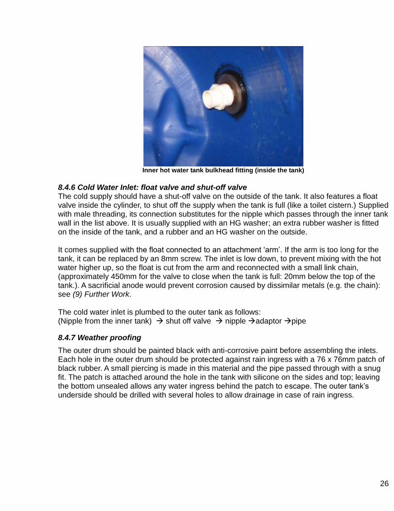
Inner hot water tank bulkhead fitting (inside the tank)
8.4.6 Cold Water Inlet: float valve and shut-off valve The cold supply should have a shut-off valve on the outside of the tank. It also features a float valve inside the cylinder, to shut off the supply when the tank is full (like a toilet cistern.) Supplied with male threading, its connection substitutes for the nipple which passes through the inner tank wall in the list above. It is usually supplied with an HG washer; an extra rubber washer is fitted on the inside of the tank, and a rubber and an HG washer on the outside. It comes supplied with the float connected to an attachment „arm‟. If the arm is too long for the tank, it can be replaced by an 8mm screw. The inlet is low down, to prevent mixing with the hot water higher up, so the float is cut from the arm and reconnected with a small link chain, (approximately 450mm for the valve to close when the tank is full: 20mm below the top of the tank.). A sacrificial anode would prevent corrosion caused by dissimilar metals (e.g. the chain): see (9) Further Work. The cold water inlet is plumbed to the outer tank as follows: (Nipple from the inner tank) shut off valve nipple adaptor pipe
8.4.7 Weather proofing
The outer drum should be painted black with anti-corrosive paint before assembling the inlets. Each hole in the outer drum should be protected against rain ingress with a 76 x 76mm patch of black rubber. A small piercing is made in this material and the pipe passed through with a snug fit. The patch is attached around the hole in the tank with silicone on the sides and top; leaving the bottom unsealed allows any water ingress behind the patch to escape. The outer tank‟s underside should be drilled with several holes to allow drainage in case of rain ingress.
27
9 Further Work
There are several system changes which would be worthy of investigation
9.1 Selective-Absorber Layer for the Collector.
Currently the absorber is painted with black anti-corrosive paint or matt black. Side by side testing could compare the increased heat transfer and reduced losses resulting from matt, chalk-board and normal anti-corrosive paints. Selective-Absorber-Layer coating could also be tested: high absorption / low emission treatment used by some flat-plate collectors on the market. TiNOX, a titanium based product, is widely used, but isn‟t available in Guatemala. It‟s manufactured by a German company which offered to send AIDG a sample TiNOX coated collector absorber plate for €189 freight cost. They quoted 22-30€/ m² for commercial supply: [email protected] +49-89-147296-0
9.2 Increasing Collector Surface Area
More prototype designs could be developed and tested based on larger absorbers. This could either focus on increased serpentine area, if it is possible to reduce the bend radius and create more bends (with a longer pipe), or increasing the collector as a whole, or a combination. Increasing the serpentine area will increase efficiency/ m² of the collector. Amplifying the collector based on its current design would perhaps generate reductions in material costs; increasing laminar size may reduce cost per m² for example.
9.3 Copper: Protection against high-temperatures
The author was very surprised about the use of plastic pipes for the flow and return pipes to the solar collectors. The solar installation sector in Europe assumes that plastic pipes and fittings are unable to withstand the high temperatures generated in the collector outlet; even PEC used for under-floor heating. Even in England, where solar irradiation is relatively low, copper or occasionally steel pipes would always be used. Sadly, although solar irradiation all over Guatemala creates the potential for high temperatures, disposable income is much lower; few households would be willing to buy a SSWH unless they are as cheap as possible. At less than 1.1m² SSWH are less than half the surface areas of typical factory-produced flat plate collectors, with higher heat loss and lower absorption. System testing in Xela with two collectors resulted in temperatures lower than the maximum that supported by CPVC. Nevertheless the author supports the use of copper for the solar circuit, especially the flow from the solar panels. Leaving the house for vacation is the classic scenario in which, with no hot water use, temperatures in the tank accumulate and can reach dangerously high levels.
28
The extra cost of ½ or ¾” copper pipe locally in Xela is still to be investigated (as well as fittings, solder etc.) Costs would also be increased by the need for pipe lagging, as bare copper pipes would waste heat; this may need to be high-temperature lagging. Normally this pipe run shouldn‟t exceed a few meters, meaning extra cost maybe marginal. The issue should be studied empirically to clarify the following question; what kind of solar irradiance (in Xela and elsewhere in Guatemala), and building occupancy conditions could mean a SSWH system generates higher temperatures than is safe for CPVC (82º C)?
9.4 Collector ‘Clip Fins’
Tests could be conducted on addition of metal fins on top of the absorber pipes. The link: http://www.builditsolar.com/Experimental/CPVCCollector/jig.htm gives info on making aluminium jigs for clip fins. The instructions are for a pipe grid and so they would need to be adapted for a serpentine absorber. Similar fins made of galvanized sheet steel were tested; the temperature difference was found to be less than 1ºC between these and the wire-tied collector. The fins, however, did not cover the whole of the absorber.
9.5 Hot Water Tank: Sacrificial Anode
Corrosion around the fittings in the tank is likely to result from contact between dissimilar metals. Even without the use of copper pipes, the metals may vary: for example between the float valve and other fittings. This will lead to poorer water quality and reduced tank life. Commercially manufactured hot tanks are often protected against corrosion by a sacrificial anode: a strip of zinc or magnesium connected to the protected metal which corrodes first and generally must oxidize nearly completely before the less active metal will corrode
A sacrificial anode is defined as a metal that is more easily oxidized than the protected metal. Electrons are stripped from the anode and conducted to the protected metal, which becomes the cathode. For this mode of corrosion protection to function there must be simultaneously present an electron pathway between the anode and the metal to be protected (e.g. a wire or direct contact) and an ion pathway (e.g., water) to form a closed circuit. To limit the effect of the corrosion on water quality possibly it should be positioned in the air space at the top of the tank.
The availability of the materials for this addition has not been investigated, nor the extra cost involved.
9.6 Increased Hot Water Tank and Collector Insulation. Heat Loss Coefficients.
Various insulation materials for the hot water tank have been considered by AIDG including coffee husks or shredded polystyrene. The current Terma-flex fibre-glass insulation sheet was probably the best idea because it is readily available, safe, and easy to cut to size and store (streamlining production.) However, it is clear from the test results in 8.1.1 that there are substantial overnight heat losses from the tank. Therefore if there is high demand for daytime showers in a household in Xela the SSWH system would struggle to meet it. Elsewhere in the world cold temperatures during the day would mean the tank would be unlikely to retain heat outside.
29
Future work should focus on an empirical heat loss calculations based on the heat loss coefficients, tank area and the temperature difference between stored water and night time temperature in Xela. This should aim to recommend the appropriate insulation material (based on U-Value/ heat loss coefficient) and thickness to retain overnight temperatures. Increasing insulation would also improve collector performance. Different prototype AIDG collectors have featured rock-wool, polystyrene board, or the current Terma-flex; however technical development would benefit from side-by side performance comparison. Even comparing their U-Values may lead to improved design.
9.7 Aerator
Use of an automatic air-vent on the highest point of the flow pipe to the cylinder would allow air bubbles to be purged. If circulation is restricted and heat-transfer is poor on a system, fit an aerator (“purgador”) and compare the results. The costs and availability in Xela are unknown. See Serpentine Solar Water Heating: Guidelines for Manufacture (4.3): System Charging.
9.8 Night time Heat Loss from Tank Inlet
At night the pipe from the solar collectors feels warm where it comes out of the tank, meaning heat loss. A conventional anti-return valve would restrict day-time thermo-siphon flow. However, testing could be done with a check valve for thermo-siphon systems; comparing dawn water tank temperatures before and after fitting, and monitoring effects on thermo-siphon flow.
9.9 Inverted Return to the Collectors
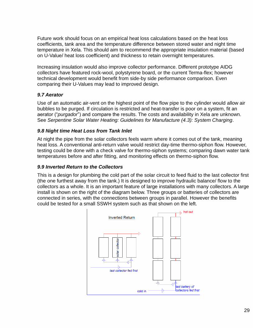
This is a design for plumbing the cold part of the solar circuit to feed fluid to the last collector first (the one furthest away from the tank.) It is designed to improve hydraulic balance/ flow to the collectors as a whole. It is an important feature of large installations with many collectors. A large install is shown on the right of the diagram below. Three groups or batteries of collectors are connected in series, with the connections between groups in parallel. However the benefits could be tested for a small SSWH system such as that shown on the left.

30
9.10 Efficiency Coefficients
Further data from system performance monitoring would allow system efficiency to be estimated more accurately. Using measured solar irradiance to calculate efficiency, rather than published data, would also be more accurate. As described in (8.2) there is a standardized formula for measuring solar collector efficiency which is less simplified. This would require calculation/ estimation of the serpentine collector‟s absorption and loss coefficients, following standardized test procedure. If it could be achieved it would substantially improve system sizing, especially for customers with large demands like a hotel.
9.11 Horizontal tanks
There are many examples of commercially manufactured thermo-siphon „kits‟ featuring an integrated mounting frame which accommodates a horizontal tank installed above the solar collectors. The advantage of developing a similar system would be reduced heat and friction losses in the connection pipe work. However skilled engineering would be required to design such a mounting frame. The design process would be time consuming and there would be no guarantee of developing a cost effective solution. One strategy might be to copy an existing mounting frame available on the market, but modifying the collector and tank dimensions would call for a high level of precision. The mounting structures, often aluminium angle, must be precisely cut/ drilled to fit together. Structural calculations would be needed to confirm that the tank would be supported without crushing itself or its insulation, or shading the collectors. Stratification may reduce the efficiency of a horizontal tank if its inlets/ outlets are not positioned carefully. One application which could benefit from research in this area is SSWH installation on pitched roofs. The need for the tank to be on a higher level than the collectors means the system can be most easily installed on a flat roof. This could be solved by developing an integrated mounting system anchored to the rafters under the tiles which would support a horizontal tank above the collectors. One of the issues involved in developing such a solution would be a weather-proof roof penetration for the pipes.
31
10. Material Costs in Guatemala
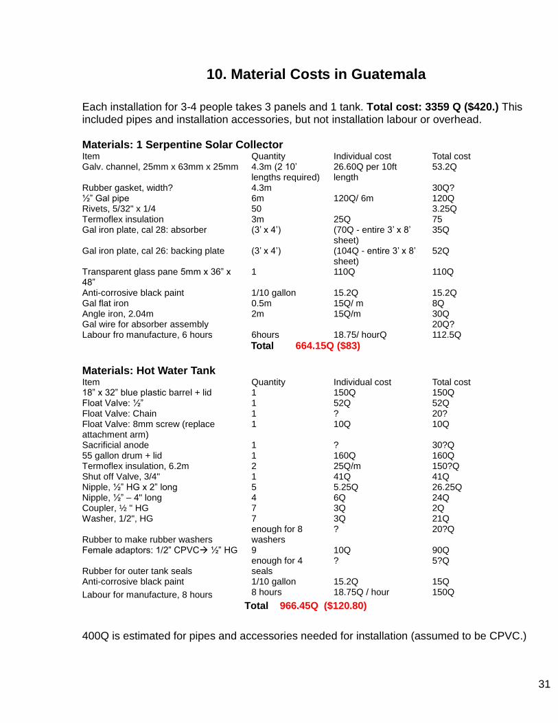
Each installation for 3-4 people takes 3 panels and 1 tank. Total cost: 3359 Q ($420.) This included pipes and installation accessories, but not installation labour or overhead. Materials: 1 Serpentine Solar Collector Item Quantity Individual cost Total cost Galv. channel, 25mm x 63mm x 25mm 4.3m (2 10‟
lengths required) 26.60Q per 10ft length
53.2Q
Rubber gasket, width? 4.3m 30Q? ½” Gal pipe 6m 120Q/ 6m 120Q Rivets, 5/32" x 1/4 50 3.25Q Termoflex insulation 3m 25Q 75 Gal iron plate, cal 28: absorber (3‟ x 4‟) (70Q - entire 3‟ x 8‟
sheet) 35Q
Gal iron plate, cal 26: backing plate (3‟ x 4‟) (104Q - entire 3‟ x 8‟ sheet)
52Q
Transparent glass pane 5mm x 36” x 48”
1 110Q 110Q
Anti-corrosive black paint 1/10 gallon 15.2Q 15.2Q Gal flat iron 0.5m 15Q/ m 8Q Angle iron, 2.04m 2m 15Q/m 30Q Gal wire for absorber assembly 20Q? Labour fro manufacture, 6 hours 6hours 18.75/ hourQ 112.5Q
Total 664.15Q ($83)
Materials: Hot Water Tank Item Quantity Individual cost Total cost 18” x 32” blue plastic barrel + lid 1 150Q 150Q Float Valve: ½” 1 52Q 52Q Float Valve: Chain 1 ? 20? Float Valve: 8mm screw (replace attachment arm)
1 10Q 10Q
Sacrificial anode 1 ? 30?Q 55 gallon drum + lid 1 160Q 160Q Termoflex insulation, 6.2m 2 25Q/m 150?Q Shut off Valve, 3/4" 1 41Q 41Q Nipple, ½” HG x 2” long 5 5.25Q 26.25Q Nipple, ½” – 4" long 4 6Q 24Q Coupler, ½ " HG 7 3Q 2Q Washer, 1/2", HG 7 3Q 21Q
Rubber to make rubber washers enough for 8 washers
? 20?Q
Female adaptors: 1/2” CPVC ½” HG 9 10Q 90Q
Rubber for outer tank seals enough for 4 seals
? 5?Q
Anti-corrosive black paint 1/10 gallon 15.2Q 15Q
Labour for manufacture, 8 hours 8 hours 18.75Q / hour 150Q
Total 966.45Q ($120.80)
400Q is estimated for pipes and accessories needed for installation (assumed to be CPVC.)
32
11 Conclusions
There is a huge gap between what Guatemalans are willing to pay for solar water heating, 1000Q (3.1), and the system cost, 3359Q. As a result the Serpentine Solar Collectors are going on the AIDG back-burner. Does this mean it is a worthless technology? As estimated in Section 3.6, a SSWH system could save up to 1145Q/ year in Guatemala, generating a phenomenal payback of less than 3 years. The technological development of SSWH has benefited from lengthy research by AIDG. The result is a durable system which consistently performs well in the Guatemalan climate; at 10% of the installed cost of domestic solar water heating in Europe. Rather than excluding the technology because of this gap, other methods of distribution could be considered. Solar water heaters at a viable cost in Guatemala are bound to have performance or durability flaws. Organizations might consider charging these rates (around 1000Q) for a proven system like SSWH, whilst sourcing external funding to subsidise the extra cost. One approach could be to exploit the incredible cost difference between SSWH and solar systems in the US and Europe and try to generate sales/ installations in these regions. Obstacles would include climatic differences and Building Regulations; but there may be long term profits which could subsidise SSWH in Guatemala. Another idea to research is solar rental in Guatemala. With the help of capital funding the systems could be rented to families at a monthly rate tied to the projected savings (1000Q per year.) In potentially 3 years the rental payments would become a continuous income source for the providing business. The SSWH development programme at AIDG has been weak on marketing and promotion. The existence of other solar thermal manufacturers/ installers in Guatemala indicates that there is a target market. There may be benefits from copying other companies‟ strategies for identifying customers and marketing. Eco-hotels have been talked about as a target market; as shown in A2.1 this would require detailed system sizing and larger tank design. Pedro, a former Xelateco engineer and our Title Page star, believes that environmental awareness is generally the issue; Guatemalans need to be better educated about environmental problems before they see the benefit of this technology. He claims that take-up would benefit more from improving performance than reducing costs. People in Guatemala like the instantaneous convenience of electric water heating and are not convinced that SSWH would work in the morning. In this case, the solution is to improve performance (e.g. tank efficiency) while becoming active in environmental education. The biggest change in the Serpentine design has been the replacement of the wooden frame with metal. Although this overcomes the durability issues of wood, the previous wood and rock-wool combination would have been a better insulator than gal. channel and Termo-flex. Possibly the optimal design would feature wooden sides with metal cladding for weather protection (with a gal lamina backing and rock-wool type insulation.)
33
Appendix 1 Risk of Legionnaires Disease
Many countries legally require hot water tanks to be maintained above 50-60° to prevent the incubation of Legionela bacteria. Water stored at 30-50° is considered high risk for the growth of this bacteria, which, transmitted by an aerosol such as a shower, can result in Legionnaires disease. Legionnaires has similar symptoms to pneumonia, and can be fatal for old or frail people. The disease is explained at: www.en.wikipedia.org/wiki/Legionnellosis.)
With no auxiliary heating provision for the tank, this Legionela prevention measure is impossible for the Solar Serpentine systems. However various alternative methods of Legionaires prevention in hot water tanks and water systems generally are available. Chlorination on a regular basis or hyper-chlorination are the most common. Use of Chlorine Dioxide, mono-chloramines and Ionization are also possible. Info is available: (http://www.ewgli.org/data/european_guidelines/eg_supplement1b.pdf.) SSWH customers should receive a System User Manual outlining Legionela risk and recomendations for prevention.
Appendix 2 Existing Installation Case Studies
A2.1 Nueva Alianza Hotel
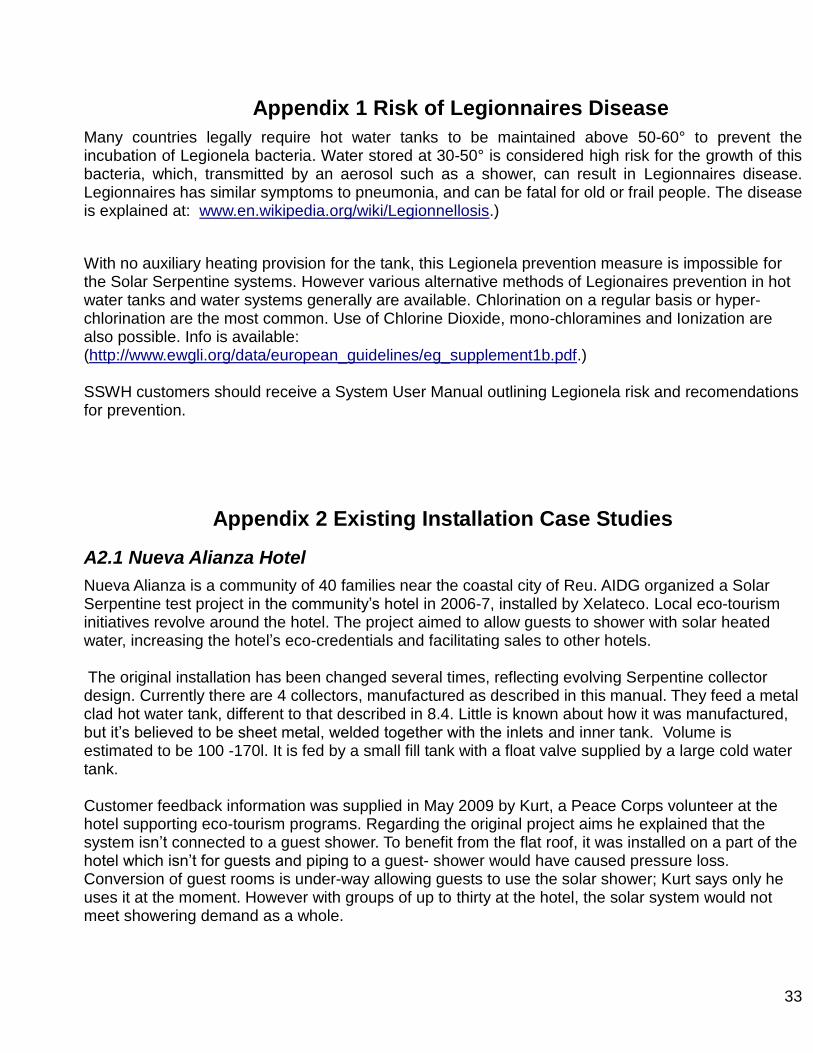
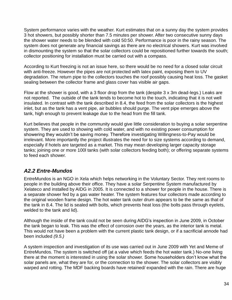
Nueva Alianza is a community of 40 families near the coastal city of Reu. AIDG organized a Solar Serpentine test project in the community‟s hotel in 2006-7, installed by Xelateco. Local eco-tourism initiatives revolve around the hotel. The project aimed to allow guests to shower with solar heated water, increasing the hotel‟s eco-credentials and facilitating sales to other hotels. The original installation has been changed several times, reflecting evolving Serpentine collector design. Currently there are 4 collectors, manufactured as described in this manual. They feed a metal clad hot water tank, different to that described in 8.4. Little is known about how it was manufactured, but it‟s believed to be sheet metal, welded together with the inlets and inner tank. Volume is estimated to be 100 -170l. It is fed by a small fill tank with a float valve supplied by a large cold water tank. Customer feedback information was supplied in May 2009 by Kurt, a Peace Corps volunteer at the hotel supporting eco-tourism programs. Regarding the original project aims he explained that the system isn‟t connected to a guest shower. To benefit from the flat roof, it was installed on a part of the hotel which isn‟t for guests and piping to a guest- shower would have caused pressure loss. Conversion of guest rooms is under-way allowing guests to use the solar shower; Kurt says only he uses it at the moment. However with groups of up to thirty at the hotel, the solar system would not meet showering demand as a whole.
34
System performance varies with the weather. Kurt estimates that on a sunny day the system provides 3 hot showers, but possibly shorter than 7.5 minutes per shower. After two consecutive sunny days the shower water needs to be blended with cold 50:50. Performance is poor in the rainy season. The system does not generate any financial savings as there are no electrical showers. Kurt was involved in dismounting the system so that the solar collectors could be repositioned further towards the south; collector positioning for installation must be carried out with a compass. According to Kurt freezing is not an issue here, so there would be no need for a closed solar circuit with anti-freeze. However the pipes are not protected with latex paint, exposing them to UV degradation. The return pipe to the collectors touches the roof possibly causing heat loss. The gasket sealing between the collector frame and glass cover has visible air gaps. Flow at the shower is good, with a 3 floor drop from the tank (despite 3 x 3m dead-legs.) Leaks are not reported. The outside of the tank tends to become hot to the touch, indicating that it is not well insulated. In contrast with the tank described in 8.4, the feed from the solar collectors is the highest inlet, but as the tank has a vent pipe, air bubbles should purge. The vent pipe emerges above the tank, high enough to prevent leakage due to the head from the fill tank. Kurt believes that people in the community would give little consideration to buying a solar serpentine system. They are used to showing with cold water, and with no existing power consumption for showering they wouldn‟t be saving money. Therefore investigating Willingness-to-Pay would be irrelevant. More importantly the project illustrates the need for to size systems according to demand, especially if hotels are targeted as a market. This may mean developing larger capacity storage tanks; joining one or more 100l tanks (with solar collectors feeding both); or offering separate systems to feed each shower.
A2.2 Entre-Mundos
EntreMundos is an NGO in Xela which helps networking in the Voluntary Sector. They rent rooms to people in the building above their office. They have a solar Serpentine System manufactured by Xelateco and installed by AIDG in 2005. It is connected to a shower for people in the house. There is a separate shower fed by a gas water heater. The system features four collectors made according to the original wooden frame design. The hot water tank outer drum appears to be the same as that of the tank in 8.4. The lid is sealed with bolts, which prevents heat loss (the bolts pass through eyelets, welded to the tank and lid). Although the inside of the tank could not be seen during AIDG‟s inspection in June 2009, in October the tank began to leak. This was the effect of corrosion over the years, as the interior tank is metal. This would not have been a problem with the current plastic tank design, or if a sacrificial annode had been included (9.5.) A system inspection and investigation of its use was carried out in June 2009 with Yet and Meme of EntreMundos. The system is switched off (at a valve which feeds the hot water tank.) No-one living there at the moment is interested in using the solar shower. Some householders don‟t know what the solar panels are, what they are for, or the connection to the shower. The solar collectors are visibly warped and rotting. The MDF backing boards have retained/ expanded with the rain. There are huge
35
gaps therefore in the collector allowing heat to escape. Not surprisingly therefore, Meme says that their performance is far worse than when they were installed. Yet thinks that a hot shower from the system wouldn‟t last more than 5 minutes; she doesn‟t really know as it isn‟t in use. The system is installed on a pitched roof, proving that this is possible; although the frame for the tank (to bring it to a higher level than the collectors) would certainly add time and expense, and it does not appear to be robustly anchored to the lower section of roof. A platform had to be built into the roof as a level base for this structure. Access is poor with little space behind and in front of the collectors; maintenance work would be dangerous without scaffolding/ edge protection. The flow and return pipes to/ from the collector were originally covered with lagging/ pipe insulation. This was originally protected against UV degradation by aluminium tape; however the tape came off and the pipe insulation broke off and flew away (people in the house thought that it was snowing!) Almost all the nuts and bolts and screws appear to be rusty; stainless steel nuts and bolts could be worth the extra cost. There is no explanatory information for building users on the solar system and it‟s benefits; identifying the solar and the gas fed shower; which valve to use for cold water mixing to limit scalding risk etc. This should be a standard feature of future installations.
A2.2.2 Update 2010
During the last months of 2009 the solar collectors and the tank were replaced by Ben Dana. The new solar collectors feature the metal framing outlined in this manual. The tank follows the plastic inner barrel design also in this manual.
A2.3 La Guarderia, Llanos del Pinal
This is a Day-Centre for Children in a village outside Xela. Their SSWH system was installed as a donation from AIDG as part of a shower block that was built at the time (2005-6.) The collectors are based on the same wooden frame design used at Entre-Mundos but have somehow survived weathering much better. The frames are not noticeably rotting, and Leticia who manages the project reports that it performs well throughout the year.
The system is used by three children for daily showering, one first thing in the morning and two in the afternoon. Showers last approximately 15 minutes. Leticia says that it can provide up to six showers a day. There is overnight heat loss, however, meaning the water is not hot enough first thing in the morning. This was much less of a problem according to Leticia before the pipe lagging broke off and flew away (as happened at EntreMundos.) There is no alternative water heating provision. Shower flow is good; even though the head difference from the tank is not great, horizontal runs are short.
Installers had to make innovative use of a very tight roof space to squeeze in 3 collectors and a tank. The collectors had to be installed slightly diagonally across the roof, and the proximity of the tank probably causes shading at some points of the day. As there is not enough space on the flat roof of the shower block the installation is extended over to an adjacent pitched lamina roof. As a result the mounting system does not appear very robust with the second collector just supported against a beam. To an outsider‟s eye this is vulnerable in a hurricane zone, but it has allowed the system to work for three years now.
36