Seismic Guidelines for Water Pipelines March 2005 · Seismic Guidelines for ... 103 8.1.14...
66
AmericanLifelinesAlliance A public-private partnership to reduce risk to utility and transportation systems from natural hazards and manmade threats Seismic Guidelines for Water Pipelines March 2005
-
Upload
nguyendieu -
Category
Documents
-
view
216 -
download
0
Transcript of Seismic Guidelines for Water Pipelines March 2005 · Seismic Guidelines for ... 103 8.1.14...

AmericanLifelinesAlliance A public-private partnership to reduce risk to utility and transportation systems from natural hazards and manmade threats
Seismic Guidelines for
Water Pipelines
March 2005
AmericanLifelinesAlliance A public-private partnership to reduce risk to utility and transportation systems from natural hazards and manmade threats
Seismic Guidelines for
Water Pipelines
March 2005
www.americanlifelinesalliance.org
This report was written under contract to the American Lifelines Alliance, a public-private partnership between the Federal Emergency Management Agency (FEMA) and the National Institute of Building Sciences (NIBS). This report was prepared by a team representing practicing engineers in the United States water utility industry and academics.
Acknowledgements The following people and their affiliations contributed to this report.
Person Affiliation
John Eidinger (Chairman) G&E Engineering Systems Inc. Bruce Maison East Bay Municipal Utility District Luke Cheng San Francisco Public Utilities Commission Frank Collins Parsons Mike Conner San Diego Water Department Craig Davis Los Angeles Department of Water & Power Mike Matson Raines, Melton and Carella, Inc. Mike O'Rourke Rennselaer Polytechnic Institute Tom O'Rourke Cornell University Alex Tang Consultant John Wesling Geomatrix Consultants Inc. Mr. Doug Honegger provided technical oversight of this project. Mr. Joseph Steller (NIBS) provided project management for this project.
G&E would also like to thank the numerous staff of the San Francisco Public Utilities Commission, East Bay Municipal Utilities District, City of San Diego Water Department, the Los Angeles Department of Water and Power, and all the other participating agencies for their generous help.
Seismic Guidelines for Water Pipelines
Prepared for: National Institute of Building Sciences
As part of the:
American Lifelines Alliance
Prepared by:
G&E Engineering Systems Inc. 6315 Swainland Rd Oakland, CA 94611
(510) 595-9453 (510) 595-9454 (fax) [email protected]
Principal Investigator:
John Eidinger
G&E Report 80.01.01, Revision 0 March, 2005
Seismic Guidelines for Water Pipelines R80.01.01 Rev. 0
March, 2005 Page i
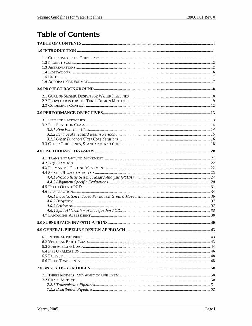
Table of Contents TABLE OF CONTENTS .................................................................................................................................... I
1.0 INTRODUCTION .........................................................................................................................................1
1.1 OBJECTIVE OF THE GUIDELINES..................................................................................................................1
1.2 PROJECT SCOPE............................................................................................................................................2
1.3 ABBREVIATIONS ..........................................................................................................................................2
1.4 LIMITATIONS................................................................................................................................................6
1.5 UNITS ...........................................................................................................................................................7
1.6 ACROBAT FILE FORMAT..............................................................................................................................7
2.0 PROJECT BACKGROUND........................................................................................................................8
2.1 GOAL OF SEISMIC DESIGN FOR WATER PIPELINES ....................................................................................8
2.2 FLOWCHARTS FOR THE THREE DESIGN METHODS.....................................................................................9
2.3 GUIDELINES CONTEXT ..............................................................................................................................12
3.0 PERFORMANCE OBJECTIVES.............................................................................................................13
3.1 PIPELINE CATEGORIES...............................................................................................................................13
3.2 PIPE FUNCTION CLASS...............................................................................................................................14
3.2.1 Pipe Function Class..........................................................................................................................14
3.2.2 Earthquake Hazard Return Periods ................................................................................................15
3.2.3 Other Function Class Considerations .............................................................................................16
3.3 OTHER GUIDELINES, STANDARDS AND CODES ........................................................................................18
4.0 EARTHQUAKE HAZARDS .....................................................................................................................20
4.1 TRANSIENT GROUND MOVEMENT ............................................................................................................21
4.2 LIQUEFACTION...........................................................................................................................................22
4.3 PERMANENT GROUND MOVEMENT ..........................................................................................................22
4.4 SEISMIC HAZARD ANALYSIS .....................................................................................................................23
4.4.1 Probabilistic Seismic Hazard Analysis (PSHA) .............................................................................24
4.4.2 Alignment Specific Evaluations .......................................................................................................28
4.5 FAULT OFFSET PGD ..................................................................................................................................31
4.6 LIQUEFACTION...........................................................................................................................................34
4.6.1 Liquefaction Induced Permanent Ground Movement ....................................................................36
4.6.2 Buoyancy ...........................................................................................................................................37
4.6.3 Settlement ..........................................................................................................................................37
4.6.4 Spatial Variation of Liquefaction PGDs .........................................................................................38
4.7 LANDSLIDE ASSESSMENT .........................................................................................................................38
5.0 SUBSURFACE INVESTIGATIONS........................................................................................................40
6.0 GENERAL PIPELINE DESIGN APPROACH......................................................................................43
6.1 INTERNAL PRESSURE .................................................................................................................................43
6.2 VERTICAL EARTH LOAD............................................................................................................................43
6.3 SURFACE LIVE LOAD.................................................................................................................................44
6.4 PIPE OVALIZATION ....................................................................................................................................46
6.5 FATIGUE .....................................................................................................................................................48
6.6 FLUID TRANSIENTS....................................................................................................................................48
7.0 ANALYTICAL MODELS..........................................................................................................................50
7.1 THREE MODELS, AND WHEN TO USE THEM.............................................................................................50
7.2 CHART METHOD ........................................................................................................................................50
7.2.1 Transmission Pipelines.....................................................................................................................51
7.2.2 Distribution Pipelines.......................................................................................................................52
Seismic Guidelines for Water Pipelines R80.01.01 Rev. 0
March, 2005 Page ii
7.2.3 Service Laterals and Hydrant Laterals ...........................................................................................53
7.2.4 Design Approach ..............................................................................................................................54
7.3 EQUIVALENT STATIC METHOD .................................................................................................................57
7.3.1 Analysis for Ground Shaking Hazard..............................................................................................57
7.3.2 Landslide and Liquefaction Permanent Ground Deformations.....................................................64
7.3.3 Analysis for Fault Crossing Ground Displacement Hazard .........................................................72
7.4 FINITE ELEMENT METHOD ........................................................................................................................74
7.4.1 Pipe Modeling Guidelines ................................................................................................................76
7.4.2 Soil Modeling Guidelines .................................................................................................................76
7.4.3 Wrinkling Limit .................................................................................................................................85
7.4.4 Tensile Strain Limit...........................................................................................................................87
8.0 TRANSMISSION PIPELINES..................................................................................................................88
8.1 SEISMIC DESIGN ISSUES RELATED TO TRANSMISSION PIPELINES ...........................................................88
8.1.1 Seismic Hazards and Geotechnical Assessment .............................................................................88
8.1.2 Pipe Materials and Wall Thickness .................................................................................................89
8.1.3 Design Earthquakes..........................................................................................................................89
8.1.4 Pipeline Alignment............................................................................................................................90
8.1.5 Soil Mitigation...................................................................................................................................90
8.1.6 Pipe Joints .........................................................................................................................................90
8.1.7 Pipe Structural Design and Analysis ...............................................................................................98
8.1.8 Pipe Supports ....................................................................................................................................99
8.1.9 Pipe Depth and Trench Backfill.....................................................................................................101
8.1.10 Pipe Bend and Thrust Block Design............................................................................................101
8.1.11 Design Features and Appurtenances...........................................................................................101
8.1.12 System Redundancy ......................................................................................................................103
8.1.13 System Modeling ...........................................................................................................................103
8.1.14 Corrosion Control ........................................................................................................................104
8.1.15 Internal Pressure and External Loads ........................................................................................105
8.1.16 Constructability.............................................................................................................................106
8.1.17 Economic Considerations ............................................................................................................106
8.1.18 Environmental Issues....................................................................................................................106
8.1.19 Public Relation or Outreach ........................................................................................................106
8.1.20 Emergency Response Planning....................................................................................................107
8.1.21 Security ..........................................................................................................................................108
8.1.22 Other Special Design Issues.........................................................................................................109
8.2 DESIGN CONSIDERATIONS AT FAULT CROSSINGS..................................................................................109
8.2.1 Fault Types and Fault Zones..........................................................................................................109
8.2.2 Orientation of Pipe with Respect to the Fault Line ......................................................................110
8.2.3 Design Earthquakes and Associated Magnitude of Fault Displacements ..................................110
8.2.4 Geotechnical Hazards ....................................................................................................................111
8.2.5 Soil-Pipeline Interaction ................................................................................................................111
8.2.6 Joints Used to Accommodate Fault Displacements......................................................................111
8.2.7 Analysis Methods ............................................................................................................................113
8.2.8 Design Redundancy ........................................................................................................................114
9.0 SUB-TRANSMISSION PIPELINES ......................................................................................................116
9.1 DESIGN USING THE CHART METHOD......................................................................................................116
9.2 FAULT, LANDSLIDE AND LIQUEFACTION ZONE CROSSINGS .................................................................117
Hazard Bypass System .............................................................................................................................117
9.2.1 Location of isolation valves for bypass relative to mapped hazard ............................................120
9.2.2 Bypass System Components ...........................................................................................................121
9.2.3 Coating System Details...................................................................................................................121
9.2.4 Purchase Specifications for Bypass System Components ............................................................122
9.2.5 Isolation Valve Approach Near Hazards ......................................................................................122
9.2.6 Automation of Isolation Valves ......................................................................................................122
Seismic Guidelines for Water Pipelines R80.01.01 Rev. 0
March, 2005 Page iii
9.3 AVOIDANCE/RELOCATION OF SUB-TRANSMISSION PIPELINE OUT OF HAZARD AREA ........................123
9.3.1 Fault Crossings ...............................................................................................................................123
9.3.2 Landslides........................................................................................................................................123
9.3.3 Areas of Potential Liquefaction .....................................................................................................124
9.4 LIQUEFACTION INDUCED SETTLEMENT ..................................................................................................124
9.4.1 Accommodating Settlements Using Semi-Restrained and Unrestrained Pipe............................124
9.4.2 Accommodating Settlements using Butt Welded Steel Pipe and Butt Fused HDPE Pipe..........124
9.5 SPECIALIZED FITTINGS AND CONNECTIONS ...........................................................................................125
10.0 DISTRIBUTION PIPELINES ...............................................................................................................132
10.1 CAST IRON PIPE .....................................................................................................................................133
10.2 DUCTILE IRON PIPE ...............................................................................................................................133
10.3 PVC PIPE ...............................................................................................................................................137
10.4 HIGH DENSITY POLYETHYLENE PIPE....................................................................................................138
10.5 PERFORMANCE OF COMMON PIPE JOINTS UNDER AXIAL LOADS .......................................................138
10.6 SEISMIC DESIGN RECOMMENDATIONS FOR DISTRIBUTION PIPELINES ...............................................139
10.7 STANDARD INSTALLATION BASED ON AWWA GUIDELINES..............................................................140
11.0 SERVICE AND HYDRANT LATERALS...........................................................................................145
11.1 TYPICAL CUSTOMER SERVICE AND FIRE HYDRANT LATERAL............................................................145
11.2 SEISMIC HAZARDS AND EFFECTS ON APPURTENANCES ......................................................................146
11.3 DESIGN FOR INERTIAL SEISMIC MOTIONS ...........................................................................................146
11.4 DESIGN FOR WAVE PROPAGATION GROUND STRAINS (PGV)............................................................148
11.5 DESIGN FOR PERMANENT GROUND DISPLACEMENT ...........................................................................148
11.5.1 Customer Services ........................................................................................................................149
11.5.2 Fire Hydrant Laterals...................................................................................................................149
12.0 OTHER COMPONENTS.......................................................................................................................156
12.1 EBAA IRON BALL JOINTS AT FAULT CROSSINGS................................................................................156
12.2 EQUIPMENT CRITERIA ...........................................................................................................................158
13.0 REFERENCES.........................................................................................................................................164
C1.0 COMMENTARY ....................................................................................................................................170
C1.1 OBJECTIVE OF THE GUIDELINES ...........................................................................................................170
C1.2 PROJECT SCOPE.....................................................................................................................................171
C1.4 LIMITATIONS .........................................................................................................................................171
C2.0 PROJECT BACKGROUND.................................................................................................................172
C2.2 HYDRODYNAMIC LOADING ..................................................................................................................172
C2.3 GUIDELINES CONTEXT..........................................................................................................................173
C3.0 PERFORMANCE OBJECTIVES........................................................................................................178
C3.1 CATEGORIES OF PIPELINES ...................................................................................................................178
C3.2 PIPE FUNCTION CLASS..........................................................................................................................179
C3.2.1 Pipe Function Class .....................................................................................................................179
C3.2.2 Earthquake Hazard Return Periods............................................................................................183
C3.2.3 Other Function Class Considerations ........................................................................................185
C3.3 OTHER GUIDELINES, STANDARDS AND CODES ...................................................................................191
C3.3.1 2003 International Building Code ..............................................................................................191
C3.3.2 ASCE 7-02. ...................................................................................................................................193
C3.3.3 1997 NEHRP provisions..............................................................................................................194
C3.3.4 1997 Uniform Building Code (UBC) ..........................................................................................194
C3.3.5 1997 JWWA Guidelines ...............................................................................................................195
C3.3.6 ASCE 1984....................................................................................................................................197
C3.3.7 ASCE-ASME 2001........................................................................................................................197

Seismic Guidelines for Water Pipelines R80.01.01 Rev. 0
March, 2005 Page iv
C3.3.8 PRCI 2004 ....................................................................................................................................197
C4.0 EARTHQUAKE HAZARDS ................................................................................................................198
C4.1 TRANSIENT GROUND MOVEMENT .......................................................................................................198
C4.2 LIQUEFACTION ......................................................................................................................................199
C4.3 PERMANENT GROUND MOVEMENT......................................................................................................200
C4.4 SEISMIC HAZARD ANALYSIS ................................................................................................................201
C4.4.1 Probabilistic Seismic Hazard Analysis (PSHA).........................................................................202
C4.4.1.1.1 Getting PGA and PGV...........................................................................................................204
C4.4.2 Design Level PGA and PGV Values ...........................................................................................205
C4.5 FAULT OFFSET ......................................................................................................................................210
C4.6 LIQUEFACTION ......................................................................................................................................213
C4.6.1 Simplified Method to Prepare a Regional Liquefaction Map ...................................................216
C4.6.2 Buoyancy ......................................................................................................................................220
C4.6.3 Settlement......................................................................................................................................220
C4.6.4 Spatial Variation of Liquefaction PGDs ....................................................................................221
C4.6.5 Application of Regional Liquefaction Map ................................................................................221
C4.7 LANDSLIDE ASSESSMENT .....................................................................................................................221
C4.8 GROUND MOTION PARAMETERS IN OTHER CODES.............................................................................226
C5.0 SUBSURFACE INVESTIGATIONS...................................................................................................228
C6.0 GENERAL PIPELINE DESIGN APPROACH.................................................................................228
C6.6 FLUID TRANSIENTS ...............................................................................................................................229
C7.0 ANALYTICAL MODELS.....................................................................................................................229
C7.1 THREE MODELS, AND WHEN TO USE THEM........................................................................................229
C7.2 CHART METHOD ...................................................................................................................................230
C7.2.1 Design Approach..........................................................................................................................230
C7.2.2 Distribution Pipelines ..................................................................................................................231
C7.2.4 Design Approach..........................................................................................................................231
C7.3 EQUIVALENT STATIC METHOD ............................................................................................................231
C7.3.1 Analysis for Ground Shaking Hazard .........................................................................................232
C7.3.2 Analysis for Landslide and Liquefaction Hazard ......................................................................234
C7.3.3 Fault Crossing Ground Displacement Hazard ..........................................................................240
C7.4.1 Pipe Modeling Guidelines ...........................................................................................................241
C7.4.2 Soil Modeling Guidelines ............................................................................................................242
C7.4.3 Wrinkling ......................................................................................................................................242
C7.4.4 Tensile Strain Limit......................................................................................................................243
C8.0 TRANSMISSION PIPELINES.............................................................................................................244
C8.1.2 Pipe Materials and Thickness .....................................................................................................244
C8.1.3 Design Earthquakes .....................................................................................................................245
C8.1.11 Isolation Valves..........................................................................................................................248
C8.1.14 Corrosion....................................................................................................................................248
C8.1.20 Emergency Response Planning .................................................................................................248
C8.2.3 Design Earthquakes and Associated Magnitude of Fault Displacements................................250
C8.2.6 Joints Used to Accommodate Fault Displacements...................................................................250
C8.2.7 Analysis Methods .........................................................................................................................250
C10.0 DISTRIBUTION PIPELINES ............................................................................................................251
C10.2 DUCTILE IRON PIPE.............................................................................................................................251
C11.0 SERVICE LATERALS........................................................................................................................252
C11.4 DESIGN FOR TRANSIENT SEISMIC GROUND STRAINS (PGV) ...........................................................252
C11.5 DESIGN FOR PERMANENT GROUND DISPLACEMENT ........................................................................252

Seismic Guidelines for Water Pipelines R80.01.01 Rev. 0
March, 2005 Page v
C11.5.2 Fire Hydrant Laterals................................................................................................................252
C12.0 OTHER COMPONENTS....................................................................................................................253
C12.2 EQUIPMENT CRITERIA ........................................................................................................................253
C13.0 REFERENCES......................................................................................................................................254
Seismic Guidelines for Water Pipelines R80.01.01 Rev. 0
March, 2005 Page 88
8.0 Transmission Pipelines Based on statistical repair rates, like breaks per mile, there have been somewhat fewer transmission pipeline failures compared to distribution pipelines failures during past earthquakes. However, we should not be misled by this information. Because of the large sizes and lack of redundancy, the consequence of the transmission pipeline failure can be much more catastrophic. Longer down time of water supply, larger amount of water release, and more damage to the affecting area are likely events after a transmission line failure. Therefore, it is important to cover all aspects of design issues when planning and designing a transmission pipeline.
Section 8 provides general description of the major seismic design issues that should be considered during the planning and design phases of a transmission pipeline project in moderate and high seismic regions. Detailed design procedures or specific detailed information are either referenced to other sections in the Guidelines or to other publications where appropriate. The designer can also use this chapter as a checklist for planning and reviewing a transmission pipeline project.
8.1 Seismic Design Issues Related to Transmission Pipelines The general approach to design of transmission pipelines covers (1) seismic hazard and geotechnical assessment, (2) pipe materials and thicknesses, (3) design earthquakes, (4) pipeline alignment, (5) soil mitigation, (6) pipe joints, (7) pipe structural design and analysis, (8) pipe supports, (9) pipe depth and trench backfill, (10) pipe bend and thrust block design, (11) appurtenances, (12) system redundancy, (13) system modeling, (14) corrosion control, (15) internal water pressure and transient control, (16) constructability, (17) economic considerations, (18) environmental issues (19) public relation and outreach, (20) emergency response planning, and (21) security, and (22) other special design issues. General discussions on these twenty-two design issues are presented in the following sections.
8.1.1 Seismic Hazards and Geotechnical Assessment
Past earthquakes indicated that site conditions such as topography, geography, terrain and soil, have great influence on seismic damage sustained by pipes.
For every transmission pipeline project (excepting Function I), a geotechnical evaluation of the seismic hazards such as liquefaction, landslide, lateral spreading, seismic settlement, seismic wave propagation and fault crossing for each geologic area along the pipeline alignment should be performed. The evaluation should also include the impact from man-made features, such as existing retaining walls, transmission towers, cuts and fills, etc.
Detailed discussions on the hazards and assessment are covered in Chapters 4 and 5.

Seismic Guidelines for Water Pipelines R80.01.01 Rev. 0
March, 2005 Page 89
8.1.2 Pipe Materials and Wall Thickness
Transmission pipelines in the US are most commonly built from steel, prestressed concrete cylinder or reinforced concrete cylinder pipe. Smaller transmission pipelines could be built using ductile iron or high density polyethylene materials. In each case the design can use gasketed or various types of restrained joints.
The material properties of welded steel pipes should meet the requirements of AWWA C200 and steel coil produced using fine grained practice and continuous cast process. Because larger diameter pipes are usually used for transmission pipelines, the ratio of nominal diameter to thickness (D/t) should not be greater than 240. Competent engineers should do the design. In areas prone to PGDs, D/t ratios will usually be lower; at locations with abrupt and large PGDs (like fault crossings), D/t ratios should usually be 90 to 100 or less. The commentary provides further discussion of D/t ratios for welded steel pipe.
The material properties of reinforced concrete cylinder pipe should meet the requirements of AWWA C300. The material properties of prestressed concrete cylinder pipe should meet the requirements of AWWA C301. They should be carefully analyzed and designed as outlined in Section 7.
One of the most important factors in designing an earthquake resistant structure is ductility of the material. Ductility refers to the ability of the material to sustain large plastic deformation without failure. Materials of high ductility include ductile iron, welded steel and some plastic. However, in earthquakes, these materials will often only perform in a ductile manner if the pipe joinery can also accommodate the forces needed to induce generally yielding in the pipe barrel.
8.1.3 Design Earthquakes
Design earthquakes should be identified and the associated ground motion developed for each geologic area along the pipeline alignment. The procedures in Section 4 establish the ground motions as a function of Pipe Class. Most transmission pipes will be Function Class III or IV, in which case the design ground motions are taken as the 975-year or 2,475-year return period events. Looked at another way, the design motions are the usually 475-year planning level earthquake used in many codes, with a percentage increase in the ground motion such that there is a lower chance of exceedance.
For very high seismic hazard areas, the owner may wish to consider two levels of earthquakes that should be evaluated, if the owner wishes to have two levels of performance goals. For example, the owner may wish the pipe to survive high likely earthquakes that might occur in the 50 to 150 year time frame. Section C8.1.3 describes this situation.
Seismic Guidelines for Water Pipelines R80.01.01 Rev. 0
March, 2005 Page 90
8.1.4 Pipeline Alignment
Liquefaction and lateral spread susceptibility, landslide potential, seismic settlement, fault crossings, and levels of expected ground motion should be considered in pipeline alignment decisions. Alternate alignments to avoid high seismic hazard potential areas, if possible, should always be investigated. The extra cost to align a pipeline to avoid a seismic hazard may be worthwhile when considering the extra post-earthquake reliability afforded.
8.1.5 Soil Mitigation
When a pipeline alignment must go through soils with high liquefaction and lateral spread susceptibility or high landslide potential, soil stabilization should be considered. Alternatives for soil mitigation in this case might be soil nailing, vibroflotation, drainage wells, pressure grouting and underpinning the pipeline.
8.1.6 Pipe Joints
It has been observed in past earthquakes that pipes with flexible and restrained joints performed better than ones with rigid (lead caulk) or non-restrained joints.
8.1.6.1 Welded Steel Pipe
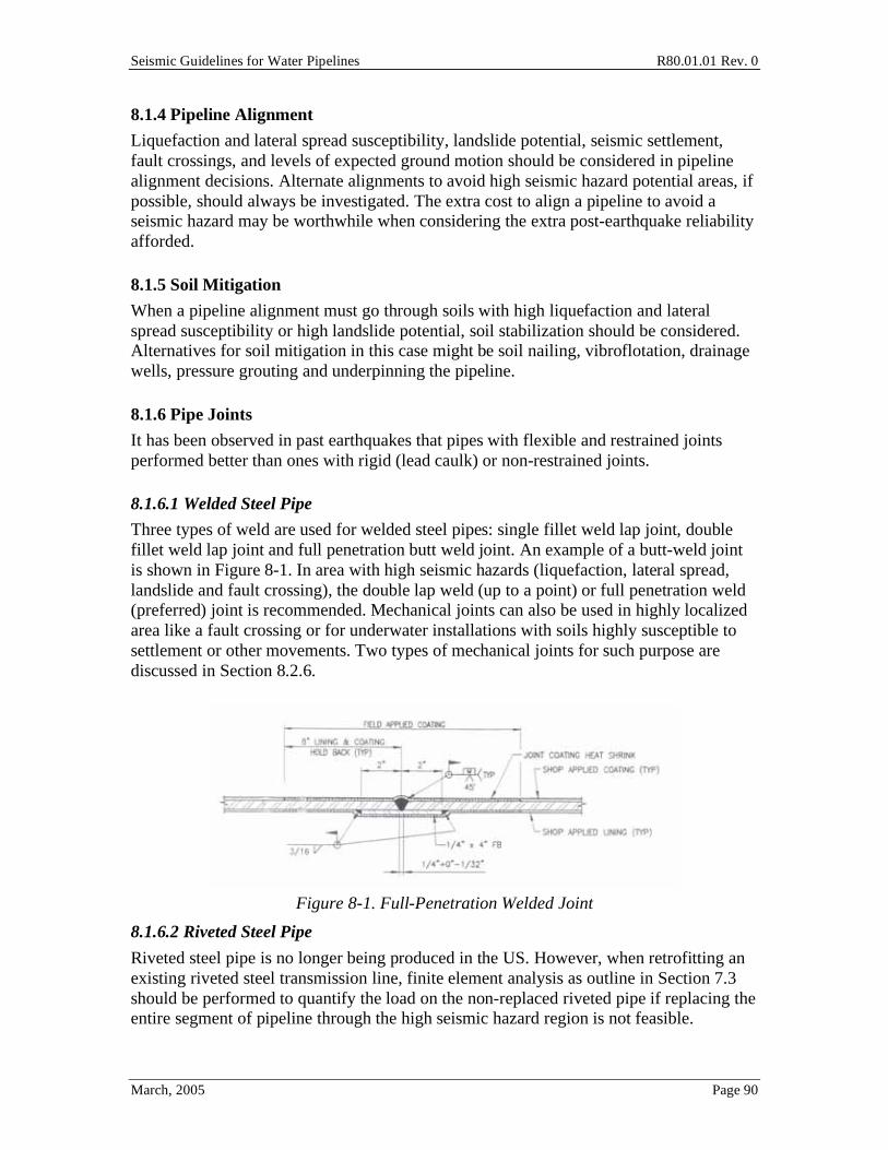
Three types of weld are used for welded steel pipes: single fillet weld lap joint, double fillet weld lap joint and full penetration butt weld joint. An example of a butt-weld joint is shown in Figure 8-1. In area with high seismic hazards (liquefaction, lateral spread, landslide and fault crossing), the double lap weld (up to a point) or full penetration weld (preferred) joint is recommended. Mechanical joints can also be used in highly localized area like a fault crossing or for underwater installations with soils highly susceptible to settlement or other movements. Two types of mechanical joints for such purpose are discussed in Section 8.2.6.
Figure 8-1. Full-Penetration Welded Joint
8.1.6.2 Riveted Steel Pipe
Riveted steel pipe is no longer being produced in the US. However, when retrofitting an existing riveted steel transmission line, finite element analysis as outline in Section 7.3 should be performed to quantify the load on the non-replaced riveted pipe if replacing the entire segment of pipeline through the high seismic hazard region is not feasible.
Seismic Guidelines for Water Pipelines R80.01.01 Rev. 0
March, 2005 Page 91
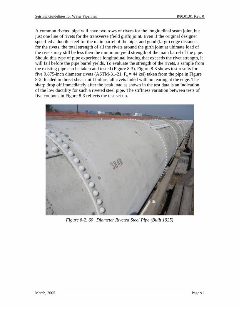
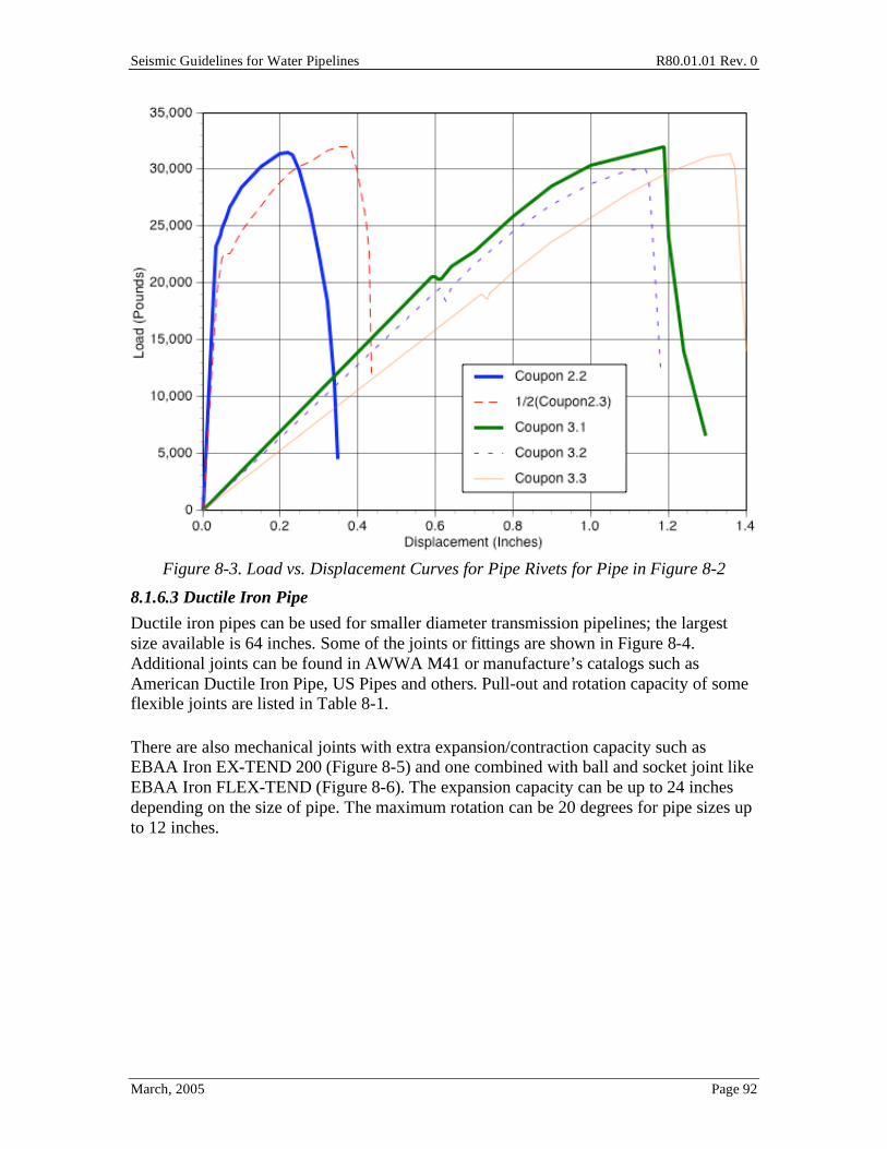
A common riveted pipe will have two rows of rivers for the longitudinal seam joint, but just one line of rivets for the transverse (field girth) joint. Even if the original designer specified a ductile steel for the main barrel of the pipe, and good (large) edge distances for the rivets, the total strength of all the rivets around the girth joint at ultimate load of the rivets may still be less then the minimum yield strength of the main barrel of the pipe. Should this type of pipe experience longitudinal loading that exceeds the rivet strength, it will fail before the pipe barrel yields. To evaluate the strength of the rivets, a sample from the existing pipe can be taken and tested (Figure 8-3). Figure 8-3 shows test results for five 0.875-inch diameter rivets (ASTM-31-21, Fu = 44 ksi) taken from the pipe in Figure 8-2, loaded in direct shear until failure; all rivets failed with no tearing at the edge. The sharp drop off immediately after the peak load as shown in the test data is an indication of the low ductility for such a riveted steel pipe. The stiffness variation between tests of five coupons in Figure 8-3 reflects the test set up.
Figure 8-2. 60" Diameter Riveted Steel Pipe (Built 1925)
Seismic Guidelines for Water Pipelines R80.01.01 Rev. 0
March, 2005 Page 92
Figure 8-3. Load vs. Displacement Curves for Pipe Rivets for Pipe in Figure 8-2
8.1.6.3 Ductile Iron Pipe
Ductile iron pipes can be used for smaller diameter transmission pipelines; the largest size available is 64 inches. Some of the joints or fittings are shown in Figure 8-4. Additional joints can be found in AWWA M41 or manufacture’s catalogs such as American Ductile Iron Pipe, US Pipes and others. Pull-out and rotation capacity of some flexible joints are listed in Table 8-1.
There are also mechanical joints with extra expansion/contraction capacity such as EBAA Iron EX-TEND 200 (Figure 8-5) and one combined with ball and socket joint like EBAA Iron FLEX-TEND (Figure 8-6). The expansion capacity can be up to 24 inches depending on the size of pipe. The maximum rotation can be 20 degrees for pipe sizes up to 12 inches.

Seismic Guidelines for Water Pipelines R80.01.01 Rev. 0
March, 2005 Page 93
Figure 8-4. Ductile Iron Pipe Joints (from DIPRA)
Seismic Guidelines for Water Pipelines R80.01.01 Rev. 0
March, 2005 Page 94
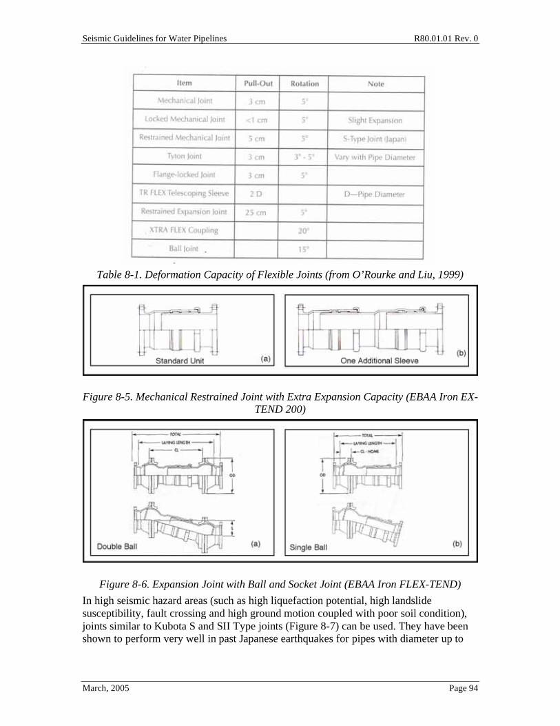
Table 8-1. Deformation Capacity of Flexible Joints (from O’Rourke and Liu, 1999)
Figure 8-5. Mechanical Restrained Joint with Extra Expansion Capacity (EBAA Iron EX-TEND 200)
Figure 8-6. Expansion Joint with Ball and Socket Joint (EBAA Iron FLEX-TEND)
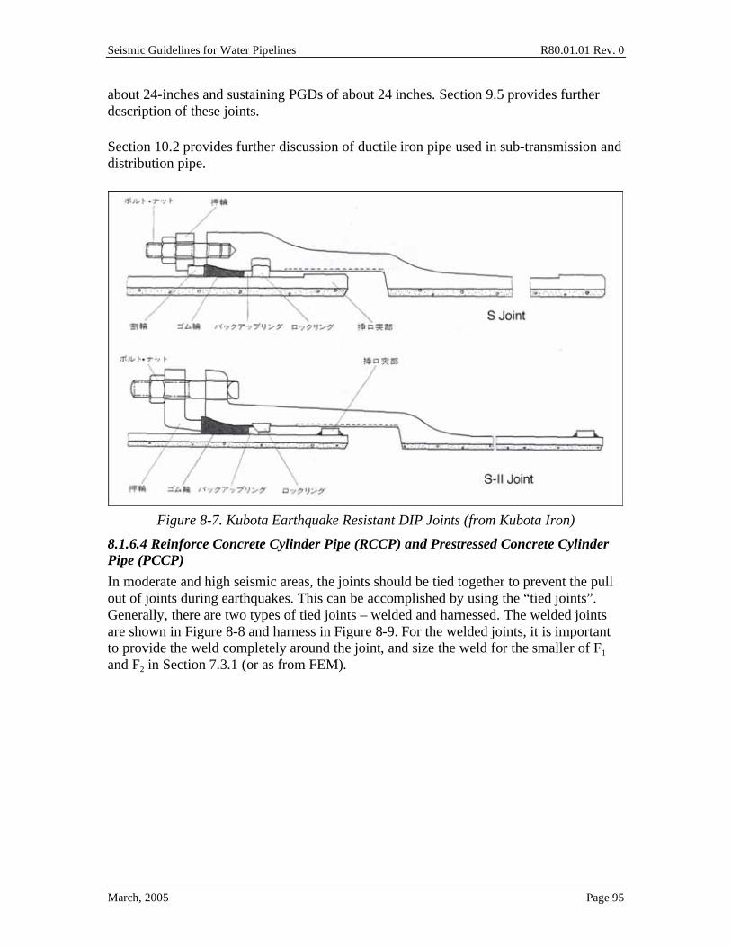
In high seismic hazard areas (such as high liquefaction potential, high landslide susceptibility, fault crossing and high ground motion coupled with poor soil condition), joints similar to Kubota S and SII Type joints (Figure 8-7) can be used. They have been shown to perform very well in past Japanese earthquakes for pipes with diameter up to
Seismic Guidelines for Water Pipelines R80.01.01 Rev. 0
March, 2005 Page 95
about 24-inches and sustaining PGDs of about 24 inches. Section 9.5 provides further description of these joints.
Section 10.2 provides further discussion of ductile iron pipe used in sub-transmission and distribution pipe.
Figure 8-7. Kubota Earthquake Resistant DIP Joints (from Kubota Iron)
8.1.6.4 Reinforce Concrete Cylinder Pipe (RCCP) and Prestressed Concrete Cylinder Pipe (PCCP)
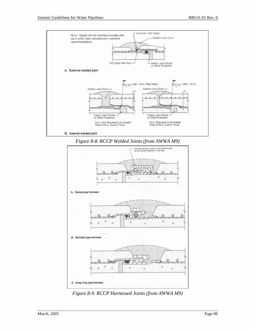
In moderate and high seismic areas, the joints should be tied together to prevent the pull out of joints during earthquakes. This can be accomplished by using the “tied joints”. Generally, there are two types of tied joints – welded and harnessed. The welded joints are shown in Figure 8-8 and harness in Figure 8-9. For the welded joints, it is important to provide the weld completely around the joint, and size the weld for the smaller of F1 and F2 in Section 7.3.1 (or as from FEM).
Seismic Guidelines for Water Pipelines R80.01.01 Rev. 0
March, 2005 Page 96
Figure 8-8. RCCP Welded Joints (from AWWA M9)
Figure 8-9. RCCP Harnessed Joints (from AWWA M9)
Seismic Guidelines for Water Pipelines R80.01.01 Rev. 0
March, 2005 Page 97
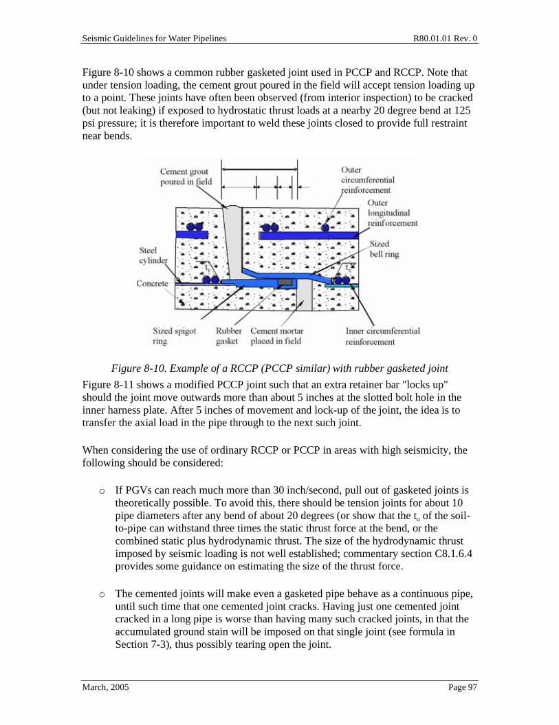
Figure 8-10 shows a common rubber gasketed joint used in PCCP and RCCP. Note that under tension loading, the cement grout poured in the field will accept tension loading up to a point. These joints have often been observed (from interior inspection) to be cracked (but not leaking) if exposed to hydrostatic thrust loads at a nearby 20 degree bend at 125 psi pressure; it is therefore important to weld these joints closed to provide full restraint near bends.
Figure 8-10. Example of a RCCP (PCCP similar) with rubber gasketed joint
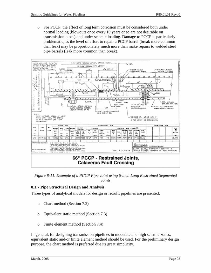
Figure 8-11 shows a modified PCCP joint such that an extra retainer bar "locks up" should the joint move outwards more than about 5 inches at the slotted bolt hole in the inner harness plate. After 5 inches of movement and lock-up of the joint, the idea is to transfer the axial load in the pipe through to the next such joint.
When considering the use of ordinary RCCP or PCCP in areas with high seismicity, the following should be considered:
o If PGVs can reach much more than 30 inch/second, pull out of gasketed joints is theoretically possible. To avoid this, there should be tension joints for about 10 pipe diameters after any bend of about 20 degrees (or show that the tu of the soil-to-pipe can withstand three times the static thrust force at the bend, or the combined static plus hydrodynamic thrust. The size of the hydrodynamic thrust imposed by seismic loading is not well established; commentary section C8.1.6.4 provides some guidance on estimating the size of the thrust force.
o The cemented joints will make even a gasketed pipe behave as a continuous pipe, until such time that one cemented joint cracks. Having just one cemented joint cracked in a long pipe is worse than having many such cracked joints, in that the accumulated ground stain will be imposed on that single joint (see formula in Section 7-3), thus possibly tearing open the joint.
Seismic Guidelines for Water Pipelines R80.01.01 Rev. 0
March, 2005 Page 98
o For PCCP, the effect of long term corrosion must be considered both under normal loading (blowouts once every 10 years or so are not desirable on transmission pipes) and under seismic loading. Damage to PCCP is particularly problematic, as the level of effort to repair a PCCP barrel (break more common than leak) may be proportionately much more than make repairs to welded steel pipe barrels (leak more common than break).
Figure 8-11. Example of a PCCP Pipe Joint using 6-inch Long Restrained Segmented Joints
8.1.7 Pipe Structural Design and Analysis
Three types of analytical models for design or retrofit pipelines are presented:
o Chart method (Section 7.2)
o Equivalent static method (Section 7.3)
o Finite element method (Section 7.4)
In general, for designing transmission pipelines in moderate and high seismic zones, equivalent static and/or finite element method should be used. For the preliminary design purpose, the chart method is preferred due its great simplicity.
Seismic Guidelines for Water Pipelines R80.01.01 Rev. 0
March, 2005 Page 99
If the chart method is chosen in a high seismic area without further validation by ESM or FEM, then at a minimum, the designer is highly advised to adopt only materials and pipe joinery with high ductility. Ductility is a very important factor in designing an earthquake-resistant structure. Pipe tension and compression must be taken into account in seismic design of continuous pipelines for transient ground strain. For general PGD loading, bending and shear (pipe ovalization) should also be considered.
For pipe bends and joints experiencing large deformation, non-linear thin shell finite element models can be used to quantify that stresses and strains are within allowables. Computer programs like ADINA, ABAQUS, ANSR and other nonlinear software are available for this type of analysis. If nonlinear performance of the pipe is expected, then care should be taken to avoid collapse of above ground components such as bends and miters, owing to their flexibility and stress intensification; without further validation, bending moments applied to above ground miters and bends should not exceed two times their elastic limits, unless they are suitably reinforced by flanges, encasement or other means.
Design of welded joints in steel transmission pipes is covered in Section 7. Section 7.3.1 discusses elastic stress limits, Section 7.4.3 discusses wrinkling strain limits, and Section 7.4.4 discusses tensile strain limits.
8.1.8 Pipe Supports
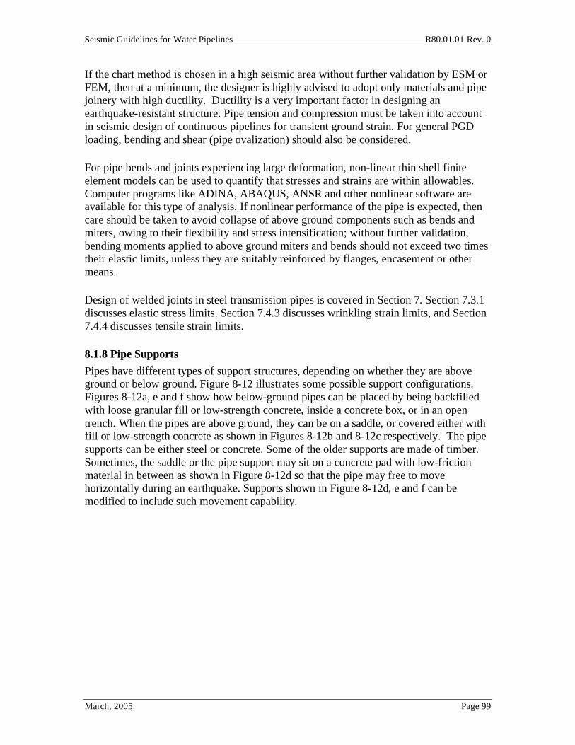
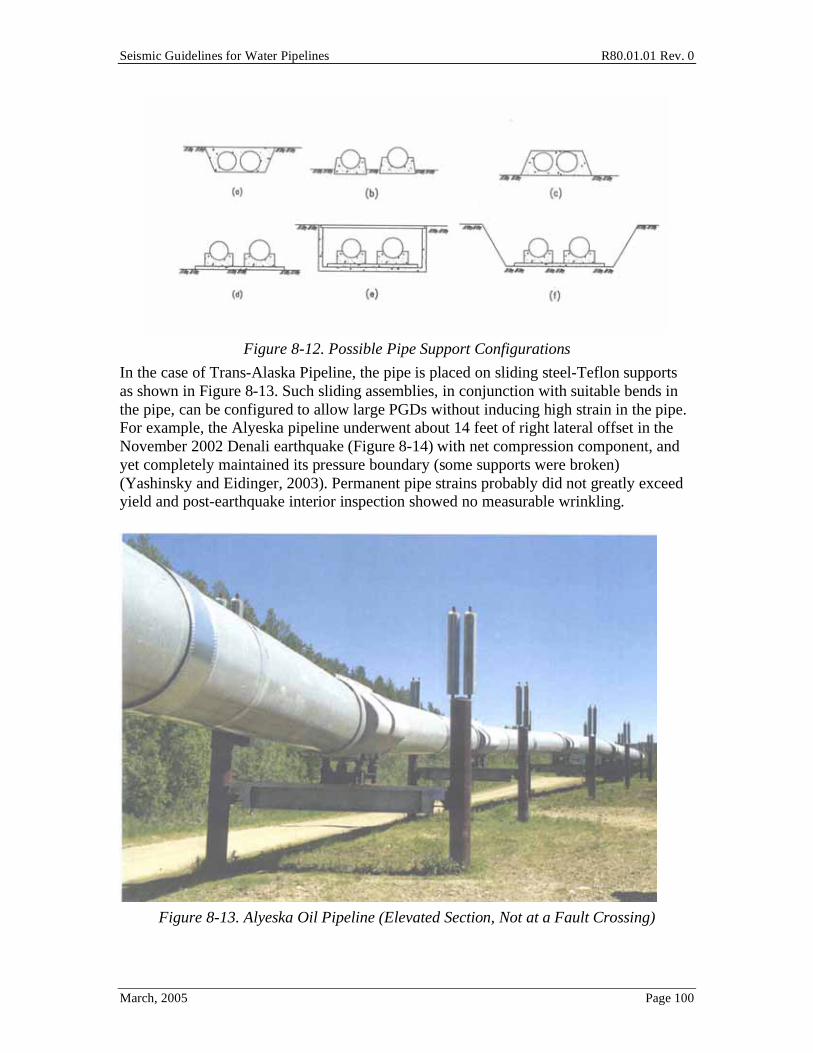
Pipes have different types of support structures, depending on whether they are above ground or below ground. Figure 8-12 illustrates some possible support configurations. Figures 8-12a, e and f show how below-ground pipes can be placed by being backfilled with loose granular fill or low-strength concrete, inside a concrete box, or in an open trench. When the pipes are above ground, they can be on a saddle, or covered either with fill or low-strength concrete as shown in Figures 8-12b and 8-12c respectively. The pipe supports can be either steel or concrete. Some of the older supports are made of timber. Sometimes, the saddle or the pipe support may sit on a concrete pad with low-friction material in between as shown in Figure 8-12d so that the pipe may free to move horizontally during an earthquake. Supports shown in Figure 8-12d, e and f can be modified to include such movement capability.
Seismic Guidelines for Water Pipelines R80.01.01 Rev. 0
March, 2005 Page 100
Figure 8-12. Possible Pipe Support Configurations
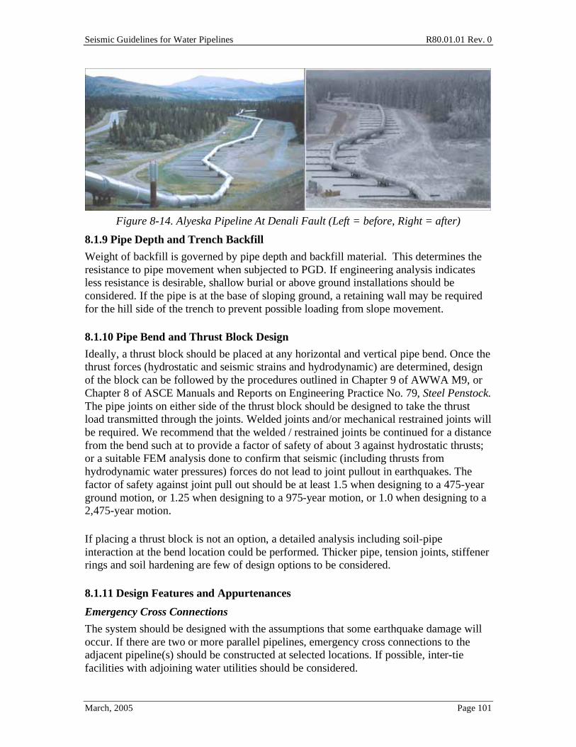
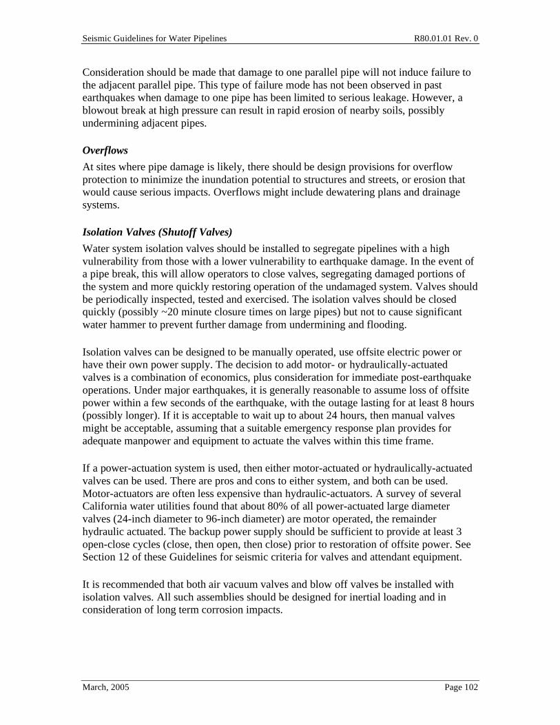
In the case of Trans-Alaska Pipeline, the pipe is placed on sliding steel-Teflon supports as shown in Figure 8-13. Such sliding assemblies, in conjunction with suitable bends in the pipe, can be configured to allow large PGDs without inducing high strain in the pipe. For example, the Alyeska pipeline underwent about 14 feet of right lateral offset in the November 2002 Denali earthquake (Figure 8-14) with net compression component, and yet completely maintained its pressure boundary (some supports were broken) (Yashinsky and Eidinger, 2003). Permanent pipe strains probably did not greatly exceed yield and post-earthquake interior inspection showed no measurable wrinkling.
Figure 8-13. Alyeska Oil Pipeline (Elevated Section, Not at a Fault Crossing)
Seismic Guidelines for Water Pipelines R80.01.01 Rev. 0
March, 2005 Page 101
Figure 8-14. Alyeska Pipeline At Denali Fault (Left = before, Right = after)
8.1.9 Pipe Depth and Trench Backfill
Weight of backfill is governed by pipe depth and backfill material. This determines the resistance to pipe movement when subjected to PGD. If engineering analysis indicates less resistance is desirable, shallow burial or above ground installations should be considered. If the pipe is at the base of sloping ground, a retaining wall may be required for the hill side of the trench to prevent possible loading from slope movement.
8.1.10 Pipe Bend and Thrust Block Design
Ideally, a thrust block should be placed at any horizontal and vertical pipe bend. Once the thrust forces (hydrostatic and seismic strains and hydrodynamic) are determined, design of the block can be followed by the procedures outlined in Chapter 9 of AWWA M9, or Chapter 8 of ASCE Manuals and Reports on Engineering Practice No. 79, Steel Penstock. The pipe joints on either side of the thrust block should be designed to take the thrust load transmitted through the joints. Welded joints and/or mechanical restrained joints will be required. We recommend that the welded / restrained joints be continued for a distance from the bend such at to provide a factor of safety of about 3 against hydrostatic thrusts; or a suitable FEM analysis done to confirm that seismic (including thrusts from hydrodynamic water pressures) forces do not lead to joint pullout in earthquakes. The factor of safety against joint pull out should be at least 1.5 when designing to a 475-year ground motion, or 1.25 when designing to a 975-year motion, or 1.0 when designing to a 2,475-year motion.
If placing a thrust block is not an option, a detailed analysis including soil-pipe interaction at the bend location could be performed. Thicker pipe, tension joints, stiffener rings and soil hardening are few of design options to be considered.
8.1.11 Design Features and Appurtenances
Emergency Cross Connections
The system should be designed with the assumptions that some earthquake damage will occur. If there are two or more parallel pipelines, emergency cross connections to the adjacent pipeline(s) should be constructed at selected locations. If possible, inter-tie facilities with adjoining water utilities should be considered.
Seismic Guidelines for Water Pipelines R80.01.01 Rev. 0
March, 2005 Page 102
Consideration should be made that damage to one parallel pipe will not induce failure to the adjacent parallel pipe. This type of failure mode has not been observed in past earthquakes when damage to one pipe has been limited to serious leakage. However, a blowout break at high pressure can result in rapid erosion of nearby soils, possibly undermining adjacent pipes.
Overflows
At sites where pipe damage is likely, there should be design provisions for overflow protection to minimize the inundation potential to structures and streets, or erosion that would cause serious impacts. Overflows might include dewatering plans and drainage systems.
Isolation Valves (Shutoff Valves)
Water system isolation valves should be installed to segregate pipelines with a high vulnerability from those with a lower vulnerability to earthquake damage. In the event of a pipe break, this will allow operators to close valves, segregating damaged portions of the system and more quickly restoring operation of the undamaged system. Valves should be periodically inspected, tested and exercised. The isolation valves should be closed quickly (possibly ~20 minute closure times on large pipes) but not to cause significant water hammer to prevent further damage from undermining and flooding.
Isolation valves can be designed to be manually operated, use offsite electric power or have their own power supply. The decision to add motor- or hydraulically-actuated valves is a combination of economics, plus consideration for immediate post-earthquake operations. Under major earthquakes, it is generally reasonable to assume loss of offsite power within a few seconds of the earthquake, with the outage lasting for at least 8 hours (possibly longer). If it is acceptable to wait up to about 24 hours, then manual valves might be acceptable, assuming that a suitable emergency response plan provides for adequate manpower and equipment to actuate the valves within this time frame.
If a power-actuation system is used, then either motor-actuated or hydraulically-actuated valves can be used. There are pros and cons to either system, and both can be used. Motor-actuators are often less expensive than hydraulic-actuators. A survey of several California water utilities found that about 80% of all power-actuated large diameter valves (24-inch diameter to 96-inch diameter) are motor operated, the remainder hydraulic actuated. The backup power supply should be sufficient to provide at least 3 open-close cycles (close, then open, then close) prior to restoration of offsite power. See Section 12 of these Guidelines for seismic criteria for valves and attendant equipment.
It is recommended that both air vacuum valves and blow off valves be installed with isolation valves. All such assemblies should be designed for inertial loading and in consideration of long term corrosion impacts.

Seismic Guidelines for Water Pipelines R80.01.01 Rev. 0
March, 2005 Page 103
Seismic or Excess Flow Activated Actuators
The isolation valves should be installed with seismic or excess flow activated actuators to prevent further damage from earthquake induced pipeline leakage or rupture. "Seismic Only" actuation (such as upon high PGA) should not be used; instead, actuation should be based on high PGA coupled with high flow / excessive pressure drop; or in many cases, only upon human operator action.
These actuators should be carefully designed to prevent unwarranted shutoff in an earthquake that does damage the pipe; or in other non-earthquake events.
Blow off (Surge) and Air Release/Vacuum Valves (Air Inlet)
Surge and/or air release valves should be considered to accommodate flows resulting from breaks that could damage the system such as a large downstream break that could result in negative pressure upstream imploding the pipe.
On large diameter pipes, blow off and air release / vacuum assemblies are often housed in circular concrete vaults (made of circular concrete pipe) overlying the transmission pipe. In areas prone to settlement PGDs, these concrete vaults can be anchored to the concrete encasement / foundations around and beneath the pipe, to avoid the potential for them displacing relative to the pipe and causing damage to the equipment within.
It is not uncommon to place air release/vacuum valves at the high points adjacent to stream crossings. If the stream embankment is prone to lateral spread, care should be take to design the concrete vault so as not to overload the pipe assembly within, or overload the transmission pipe itself. Sometimes this can be resolved by placing the concrete vault at some distance away from the creek crossing, such that it is not affected by the lateral spread.
Seismic Design of Laterals
All laterals attached to transmission pipes should be designed for seismic loads. Design procedures for appurtenances outlined in Section 11 can be followed. Air vacuum valve assemblies should be designed with special attention to avoid failures between the valve assembly and the main pipe during severe ground motion or deformation.
8.1.12 System Redundancy
Redundancy should be built into water transmission pipeline system if possible and if cost effective. Additional pipelines, multiple smaller pipelines in lieu of a single large pipeline should be considered to minimize delivery reduction due to pipe rupture. Cross connections and isolation valves as described in Section 8.1.11 should be incorporated into the system.
8.1.13 System Modeling
For a major transmission line, if the owner wishes, a system or network model for the pipeline segment being designed should be developed. The interrelationship of the

Seismic Guidelines for Water Pipelines R80.01.01 Rev. 0
March, 2005 Page 104
segment being designed to the entire system needs to be included with flow and operation perimeters determined.
In order to perform such analysis, the following information will be required:
(1) Seismic hazard mapping or assessment (liquefaction, landslide, ground motion and fault rupture) for the design segment of pipeline.
(2) Scenario earthquake(s) to be considered.
(3) System hydraulic network distribution models.
(4) Flow and operation requirements.
(5) Pipeline inventory (pipe material, size, joints, age and corrosion).
The objective of the system model analysis is able to provide the following results:
(1) Identify seismically-vulnerable segments of the pipeline.
(2) Locate potential water outage areas.
(3) Provide damage level and loss.
(4) Estimate possible repair efforts and repair times after an earthquake.
(5) Help establish suitable design criteria for the pipe to meet overall reliability targets.
With the above information, emergency response plans and mitigation procedures can then be developed.
Two examples of system models are (Eidinger, 2002a) and Ballantyne (1990).
8.1.14 Corrosion Control
Corrosion weakens the pipe’s strength. It can be a contributory cause of pipe failure during an earthquake. The corrosive environments to which a pipeline exposed could be water, atmosphere, soil, adjacent pipeline and/or structures.
Corrosion control measures include providing linings and coatings to minimize corrosion, and controlling with cathodic protection.
The pipe can be constructed with various types of materials, depending on the type of medium the pipeline carries, the internal pressure, and the dimension of the pipe, A gas pipeline is normally made of welded steel with dielectric coating and lining materials. A water transmission pipe, on the other hand, can be made of many types, such as welded steel pipe, reinforced concrete pipe, pre-stressed concrete cylinder pipe, ductile iron pipe, riveted pipe, wood-stave pipe, etc.

Seismic Guidelines for Water Pipelines R80.01.01 Rev. 0
March, 2005 Page 105
For pipelines in seismic zones prone to PGDs, selection of the interior lining and exterior coating are very important. Normally, dielectric coating and lining is more preferable than cement mortar coating and lining due to the tendency of cement mortar to crack during seismic activity.
Dielectric lining can be epoxy, polyurethane, or hot applied coal tar enamel. There are more selections for dielectric coating than the lining. In addition to these three types of material, there are also tape wrap and heat shrinkable sleeves. The tape wrap may not be a good choice for coating material due to soil stress, earth movement, and seismic activities, particularly in zones subject to PGDs; as well as its inherent weakness to construction-related damage. Tape wrap with exterior concrete armor may be preferable. In selecting the coating and lining material and the type of pipeline, a corrosion engineer should be consulted. Defects in the exterior coating will always be present after application, thus ideal protection of the pipe must include both a proper coating along with a cathodic protection system. The coating will isolate the pipe from the surrounding soil and electrically insulate most of the pipe, however, at the coating defects, the pipe will be exposed, and thus corrosion at those defects may occur. Cathodic protection, which can be by either galvanic anodes or impressed current, can prevent the exposed pipe at these defects from corroding.
Pipeline corrosion should be one of the most important things that a pipeline designer pays attention to. When designing a pipeline, one of the designer’s main concerns is that the pipe survives a seismic event. However, before any seismic event occurs, the pipeline may require excavation for leak repair if proper corrosion protection was not implemented. Dissimilar metal in the underground application can accelerate the corrosion result in unexpected leaks. Stray current interference from other DC power sources, such as a DC transit system, another cathodic protection system in the vicinity, soil corrosivity, bacteria, can be very harmful. If there is a large amount of current discharged from the pipe, a brand new pipe can leak within a few years after installation. Ground currents related to a nearby overhead electrical transmission lines can also accelerate corrosion, leading to pipe damage. There can also be safety issues when a pipeline is installed in parallel under the transmission tower.
8.1.15 Internal Pressure and External Loads
Internal water pressure should include hydrostatic and hydrodynamic pressures. The calculation procedures for water hammer effects can be found in standard hydraulics handbooks such as Handbook of Hydraulics and Hydraulic of Pipelines. Section C8.1.6.4 gives some guidance on estimation of seismically-induced hydrodynamic pressures.
The pipe also needs to be checked for external loads such as dead weight of soil, live loads, thermal loads. In some areas, the pipe needs to be checked for frost heave, nearby blasting, or other special conditions.
Seismic Guidelines for Water Pipelines R80.01.01 Rev. 0
March, 2005 Page 106
Section 6 highlights a few (but not all) of the relevant calculation checks.
8.1.16 Constructability
Construction methods should always be considered during planning and design phases. The physical site conditions and environmental issues might dictate the type of construction. The construction methods for transmission pipelines include trenching and open cut, aerial crossings, horizontal directional drilling, boring and jacking, and tunneling.
8.1.17 Economic Considerations
For transmission pipelines that are exposed to seismic hazards, part of the initial project development work should include establishment of the seismic performance criteria for the pipeline. The criteria in these Guidelines can be used for this purpose.
Meeting these criteria will involve a certain amount of cost; and earthquake-related design costs are only one of many costs. The following items might have the influence on the total cost of a transmission pipeline project: (1) pipe and casing materials availability, (2) design cost, (3) construction methods, (4) construction inspection efforts, (5) site/work area access requirements, (6) dewatering requirements, (7) right-of-way required, (8) traffic disruptions, (9) permits needed, (10) special equipment needed, (11) availability of experienced contractors, (12) contaminated soils, (13) backfill material requirements, (14) environmental impacts, (15) dust control, (16) noise reduction, (17) restoration, (18) maintenance and (19) seismic and other hazard risk.
The benefits of a pipeline include the value of the water delivered on a non-seismic basis. When considering earthquake-related design, the benefits of installing a higher quality (more seismic resistant) pipeline include the lower chance of pipe damage and attendant water loss. A comprehensive review of benefit-cost analyses for the value of water delivered post-earthquake is provided by Goettel in the ASCE Guidelines for Water Transmission Facilities (Eidinger and Avila, 1999).
8.1.18 Environmental Issues
Environmental issues have become more important for every construction project. If the project is in California, the governing laws and regulations are (a) National Environmental Policy Act (NEPA), (b) California Environmental Quality Act (CEQA), and (c) Federal and State Environmental Permits. The owner should always determine if the project is subject of NEPA and/or CEQA, and review for exemptions and complete the environmental study.
8.1.19 Public Relation or Outreach
Transmission pipelines are usually several miles long and travel through different neighborhoods in urban and rural areas. It would be prudent to present the proposed alignment and associated structures, and explain the benefits of the project and some of
Seismic Guidelines for Water Pipelines R80.01.01 Rev. 0
March, 2005 Page 107
the seismic resistance or upgrade features to the public, and solicit their input. Hopefully, by doing so, the project can avoid or minimize possible delays or unwanted lawsuits.
8.1.20 Emergency Response Planning
An emergency response plan should be in-place before the earthquake to make it part of an overall cost-effective earthquake mitigation plan.
When developing an emergency response plan, the following tasks should be considered:
(1) Establish a planning team including personnel from management, operations, safety and engineering.
(2) Complete hazards assessment and vulnerability analysis.
(3) Define emergency response categories such as
a. Minor earthquake event defined as damages confined to one location but not the whole region.
b. Moderate earthquake event defined as damages affecting multiple locations within some parts of a region and coordination among neighboring agencies might be necessary.
c. Major earthquake event defined as a disaster involving widespread damage to the whole region.
(4) Conduct condition assessment of the existing pipelines including appurtenances.
(5) Provide inventory of material for pipeline repair such as different size and material of pipes, reducers, couplings, gaskets, plates, pipe/adaptor fabrication and pipe installation/repair equipment.
(6) Conduct a survey of current staff availability.
The plan should include the following activities:
(1) Establish repair priority – In a multiple-incident or a widespread damage event, it is most important to use limited resources in the most affective way. The system model mentioned in Section 8.1.13 and knowledgeable personnel can provide very useful information for the input to establish the priority. Normally, repair priority begins with the emergency backup facilities, then moves to the sources of supply and storage, then transmission and finally distribution. Pipe repairs can not usually be done until there is water pressure available to find the damage.
Seismic Guidelines for Water Pipelines R80.01.01 Rev. 0
March, 2005 Page 108
(2) Develop repair strategy – Long term and short term repair strategies should be developed to minimize water supply interruption. For example, long term repair could be permanent fixes and short term repair could be hooking up flexible hoses at pipe rupture locations. A discussion on flexible hose and its use as a emergency bypass system is provided in Section 9.2.
(3) Set up personnel, materials and equipment requirement.
(4) Provide repair procedures.
(5) Prepare staffing and material/equipment purchasing plan.
(6) Purchase different size of pipes and reducers (or adaptors) – For emergency repairs, steel pipes are preferred as the replacement pipe because of the ease of handing.
(7) Locate stockpile sites for material and equipment – The site should be accessible, secure, in a less seismic hazard area and close to the potential pipe damage sections.
(8) Establish schedules and procedures of emergency exercises and provide training.
(9) Provide multiple locations for storage of as-built drawings and maps – the location(s) should be easily accessible during an emergency event.
(10) Establish a pipe replacement program to replace sections of aging pipeline on a regular basis (see commentary).
(11) Secure long term contracts with outside contractors for availability during a major seismic event – It might be difficult to find available contractors immediately after a major disaster.
(12) Develop a mutual aid and assistance program among utilities – One example program is the California Master Mutual Aid Agreement (MMAA). Details of the program can be found in Section 10 of Emergency Planning Guidance for Public and Private Water Utilities published by California Office of Emergency Services.
(13) Include an action item to establish a seismic upgrade program, if there is none, so that repair effort can be minimized.
8.1.21 Security
In historical context, security of water systems is not a new concept to the United States. During the 1941-1945 period, some water utilities devoted personnel to watch over surface water supplies, with concern for terrorist / war opponent impacts. Adding

Seismic Guidelines for Water Pipelines R80.01.01 Rev. 0
March, 2005 Page 109
chlorination to water supplies was partially justified as a measure to secure safe drinking water. After cessation of conflict in 1945, water utilities gradually abandoned the extra labor effort to watch over surface water supplies.
In the early 21st century, the perceived security risk to water supplies has again been elevated. In whichever way a water utility chooses to address security issues, it remains important to install new pipelines in such a manner so that security measures will not impede future repair efforts or create seismic hazards for the pipelines.
8.1.22 Other Special Design Issues
In addition to issues discussed above, other special issues might be considered:
• Waterway crossing (river/creek/channel crossing) – In this situation, liquefaction and lateral spread potential should be investigated and properly mitigated.
• Highway crossing – damage to and from the highway structure should be considered in addition to constructability.
• Bridge crossing – If the pipeline is supported by the bridge, the design of pipeline should include the response of the bridge due to seismic excitation.
• Potential impact due to failure of adjacent structures such as highway overpass, buildings, transmission towers, reservoirs and etc.
• Hydraulic transient design – Transient due to seismic load (i.e. pipe rupture or valve shut off or ground-shaking-induced water hammer) should be investigated.
8.2 Design Considerations at Fault Crossings Design considerations specific to transmission pipelines at fault crossing are: (1) fault types and fault zones, (2) orientation of the pipes with respect to the fault line, (3) design earthquakes and the associated magnitude of fault displacements, (4) geotechnical hazards, (5) soil-pipeline interaction, (6) joints used to accommodate fault displacements, i.e., expansion-contraction joints and flexible couplings, (7) analysis methods, and (8) design redundancy. These eight design considerations are discussed in the following sections.
8.2.1 Fault Types and Fault Zones
The severity of earthquake damage on a fault-crossing pipe depends on the type of fault involved. Based on a fault’s geometry and its direction of relative slip, there are three fault types: dip-slip, strike-slip, and oblique faults. Here, the strike of a fault is defined as the direction of a horizontal fault line exposed at the ground surface, and the dip is the angle at which a fault surface intercepts a horizontal plane.
Seismic Guidelines for Water Pipelines R80.01.01 Rev. 0
March, 2005 Page 110
Zones of active fault creep and subsidiary faulting are defined for the possible fault rupture region. The zone of active creep is usually defined where the most significant displacements are most likely to occur. The zone of subsidiary faulting extends on each side of the active fault creep zone. This zone consists of multiple fault planes or shear that appear to branch from, or be closely related to, the main fault trace. See Figure 4-5 for a schematic of the primary offset Zone A and the adjacent secondary offset Zones B.
8.2.2 Orientation of Pipe with Respect to the Fault Line
The orientation of a pipeline across a right-lateral strike-slip fault is the angle measured clockwise from the original pipeline position to the fault line (Figure 7-5). When a pipe’s orientation ranges from 0 to slightly less than 90 degrees, a fault movement will make the pipe elongate between anchors, and cause average axial tensile strain in the pipe; and the bending behavior will create locally high extra tension or possibly net compressive longitudinal strains. For orientations greater than about 90 degrees, the pipe will be shortened, and the resulting compressive strain can readily initiate local wrinkling (see Figure C7-2).
At all angles of crossing, a continuous pipeline will experience local bending in conjunction with axial lengthening / shortening induced tension / compression. Preferably, the crossing angle will result in sufficient axial lengthening tension to counteract the compression associated with bending.
Factors that will affect the net pipe strains given a fault offset include the pipe wall thickness, steel properties, style of backfill used in the pipe trench, friction between the pipe skin and the soil, the burial depth and the native soils behind the trench.
8.2.3 Design Earthquakes and Associated Magnitude of Fault Displacements
It should be understood that it is the owner's decision as to what is the acceptable level of performance of the pipeline, and thus the actual specification of design offset values, and allowable pipe strains, should be derived there from. However, when considering the form of Magnitude versus fault offset relationships such as Wells – Coppersmith (1994), it is generally observed that a fault that might produce a 3 to 5 foot offset at about magnitude 7, at the particular location where the pipe crosses the fault, might also produce less offset (1.5 to 3 feet) or even much larger offset (20 feet or more). In a cost effective sense, in urban environments, it might be reasonable to design the pipeline for 3 to 10 feet of offset, but availability of land, crossing of streets, etc. might make it cost prohibitive to accommodate extremely unlikely offsets of 20 feet of more. In contrast, in rural areas were land is more available, and above ground fault crossings can be tolerated, then it might not be too expensive to design for a 20 foot offset; for example, the 48-inch Alyeska oil pipeline was designed for 20 feet of offset, and survived with its pressure boundary intact, a 14 foot (by some measures, 18 foot) fault offset in the 2002 Denali earthquake in Alaska (Yashinsky and Eidinger, 2003).
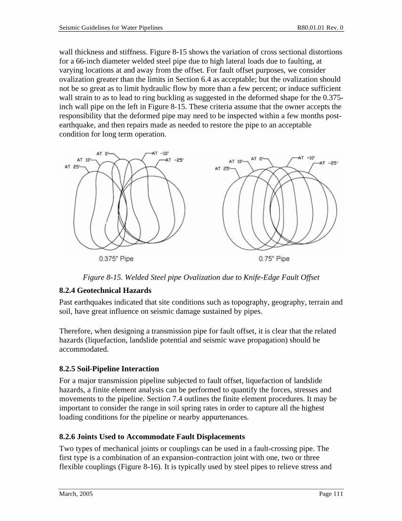
In fault crossing zones (as well as landslide and lateral spread zones), high lateral soil loading will try to ovalize a pipe, with the amount of ovalization depending upon the pipe
Seismic Guidelines for Water Pipelines R80.01.01 Rev. 0
March, 2005 Page 111
wall thickness and stiffness. Figure 8-15 shows the variation of cross sectional distortions for a 66-inch diameter welded steel pipe due to high lateral loads due to faulting, at varying locations at and away from the offset. For fault offset purposes, we consider ovalization greater than the limits in Section 6.4 as acceptable; but the ovalization should not be so great as to limit hydraulic flow by more than a few percent; or induce sufficient wall strain to as to lead to ring buckling as suggested in the deformed shape for the 0.375-inch wall pipe on the left in Figure 8-15. These criteria assume that the owner accepts the responsibility that the deformed pipe may need to be inspected within a few months post-earthquake, and then repairs made as needed to restore the pipe to an acceptable condition for long term operation.
Figure 8-15. Welded Steel pipe Ovalization due to Knife-Edge Fault Offset
8.2.4 Geotechnical Hazards
Past earthquakes indicated that site conditions such as topography, geography, terrain and soil, have great influence on seismic damage sustained by pipes.
Therefore, when designing a transmission pipe for fault offset, it is clear that the related hazards (liquefaction, landslide potential and seismic wave propagation) should be accommodated.
8.2.5 Soil-Pipeline Interaction
For a major transmission pipeline subjected to fault offset, liquefaction of landslide hazards, a finite element analysis can be performed to quantify the forces, stresses and movements to the pipeline. Section 7.4 outlines the finite element procedures. It may be important to consider the range in soil spring rates in order to capture all the highest loading conditions for the pipeline or nearby appurtenances.
8.2.6 Joints Used to Accommodate Fault Displacements
Two types of mechanical joints or couplings can be used in a fault-crossing pipe. The first type is a combination of an expansion-contraction joint with one, two or three flexible couplings (Figure 8-16). It is typically used by steel pipes to relieve stress and
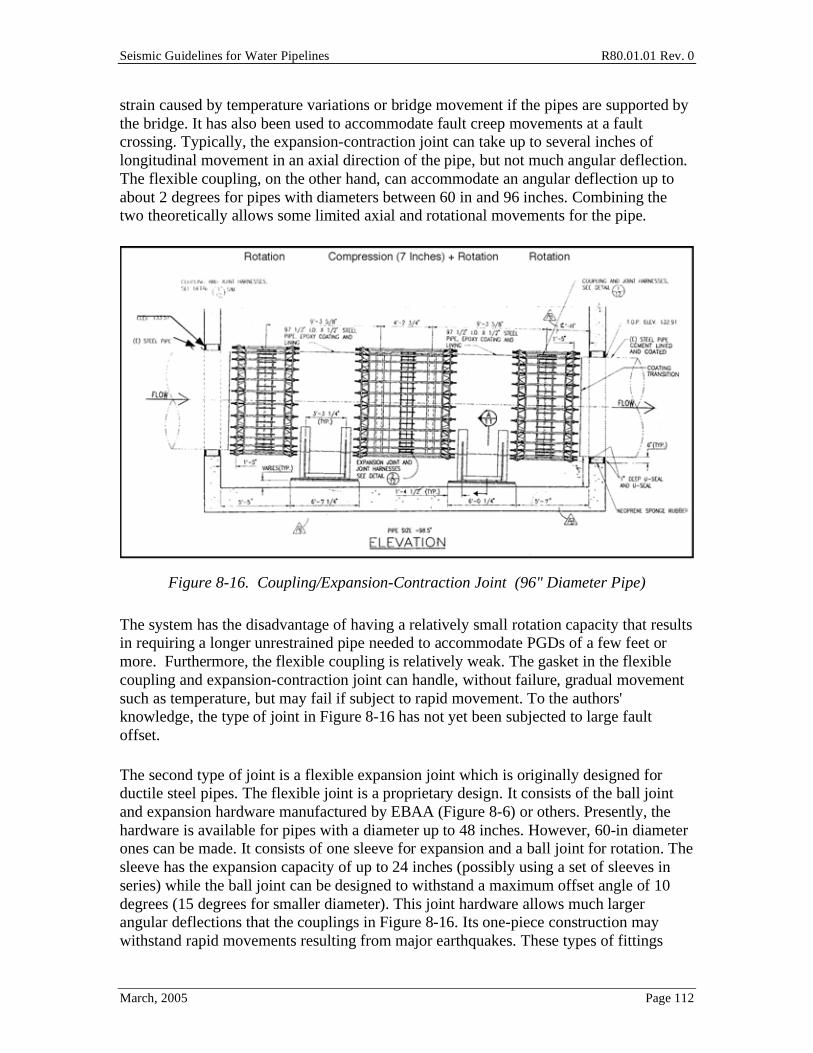
Seismic Guidelines for Water Pipelines R80.01.01 Rev. 0
March, 2005 Page 112
strain caused by temperature variations or bridge movement if the pipes are supported by the bridge. It has also been used to accommodate fault creep movements at a fault crossing. Typically, the expansion-contraction joint can take up to several inches of longitudinal movement in an axial direction of the pipe, but not much angular deflection. The flexible coupling, on the other hand, can accommodate an angular deflection up to about 2 degrees for pipes with diameters between 60 in and 96 inches. Combining the two theoretically allows some limited axial and rotational movements for the pipe.
Figure 8-16. Coupling/Expansion-Contraction Joint (96" Diameter Pipe)
The system has the disadvantage of having a relatively small rotation capacity that results in requiring a longer unrestrained pipe needed to accommodate PGDs of a few feet or more. Furthermore, the flexible coupling is relatively weak. The gasket in the flexible coupling and expansion-contraction joint can handle, without failure, gradual movement such as temperature, but may fail if subject to rapid movement. To the authors' knowledge, the type of joint in Figure 8-16 has not yet been subjected to large fault offset.
The second type of joint is a flexible expansion joint which is originally designed for ductile steel pipes. The flexible joint is a proprietary design. It consists of the ball joint and expansion hardware manufactured by EBAA (Figure 8-6) or others. Presently, the hardware is available for pipes with a diameter up to 48 inches. However, 60-in diameter ones can be made. It consists of one sleeve for expansion and a ball joint for rotation. The sleeve has the expansion capacity of up to 24 inches (possibly using a set of sleeves in series) while the ball joint can be designed to withstand a maximum offset angle of 10 degrees (15 degrees for smaller diameter). This joint hardware allows much larger angular deflections that the couplings in Figure 8-16. Its one-piece construction may withstand rapid movements resulting from major earthquakes. These types of fittings
Seismic Guidelines for Water Pipelines R80.01.01 Rev. 0
March, 2005 Page 113
have been commonly employed for accommodation of a few inches to a foot (or so) of steel tank wall uplift to attached pipes. In that type of application (commonly 12 inches to 24 inch diameter pipes), the assembly is above ground, and free from soil restraint.
For larger diameter transmission pipelines, the use of ball-and-spigot type assemblies like those in Figure 8-6 have addition constraints that can make them unsuitable for accommodating significant PGDs:
• The manufacture of the appropriate size assembly (60-inch diameter at 150 psi working pressure) has not been done through 2004, although conceptual designs have been developed. Due to pressure and size issues, the ball joint might be able to accommodate 10 degrees or rotation only.
• To accommodate a fault offset of 5 to 10 feet, and constrained to 10 degree rotations, the length of straight pipe between two ball joints gets quite large. However, in a buried pipe configuration, the straight pipe in between the two ball joints will itself be highly loaded, with possible ovalization and wrinkling issues introduced. This tendency can be reduced by placing the ball joints at closer separation distances, and using more ball joints (making a "chain".)
• As many faults have somewhat uncertain zones of deformations (A and B zones in Figure 4-5), and these zones might be from several tens of feet to a few hundred feet long, the pipe must be designed to assume offset at any location. This will often mean the placement of many ball and slip joint assemblies through the fault crossing zone. This may introduce higher construction costs then a straight butt-welded steel pipe, as well as introduce many gasket assemblies that might need to be maintained over a potentially several hundred year pipe lifetime.
• It should be recognized that the "qualification test" of typical ball-and-spigot type assemblies is typically done by pressurizing the pipe. No tests have been performed (yet) that show the nonlinear performance of a pressurized assembly to sustain fault offset loads at or larger than the design level of movement. As the amount of fault offset is an uncertain parameter, any performance-based design should consider the performance of the pipeline should larger-than-expected fault offset occur. A careful examination of the ball-and-socket and expansion joint assemblies should be done to confirm suitable stress and strain within the hardware, and gasket tolerances, at (or even somewhat above) the design offset displacements.
8.2.7 Analysis Methods
Published analysis methods for buried pipeline at fault crossing can be divided into two basic categories: simplified methods (Section 7.3) and finite element methods (section 7.4).
Seismic Guidelines for Water Pipelines R80.01.01 Rev. 0
March, 2005 Page 114
The two main simplified methods were developed by Newmark and Hall (1975) and Kennedy, Chow and Williamson (1977). Both of these methods are approximate and can be applied iteratively using hand computation. The Newmark-Hall procedure ignores local bending strain in the pipe. The Kennedy-Chow-Williamson procedure may provide a more accurate estimate of pipe strain (and higher than that predicted using the Newmark-Hall method). The Kennedy method includes the consideration of bending rigidity of a pipe. Some studies suggest that the Kennedy method might produce similar strains to those evaluated using finite element methods, under idealized conditions (constant soil parameters, constant pipe parameters, no bends, etc.). The Kennedy method is a more computationally complex than the Newmark method. In Section 7.3, we list the Newmark method, with a 2 times increase multiplier on strain to adjust for its simplicity; but this 2x multiplier may only be suitable for idealized conditions. Given that the Newmark method ignores the potential for localized bending, and that this is the observed damage mode, it is strongly advised that this simplified method be avoided for final design of any important transmission pipeline, and instead the finite element method used.
For a buried pipeline with mechanical joints or couplings, the procedures developed by O’Rourke and Trautmann (1981) can be used to evaluate the influence of different mechanical joints/couplings on pipeline performance.
Finite element methods (FEM) are more complex and require computer analysis. With widely available high-speed and large memory personal computers, this method is becoming the most preferable approach. The advantage of FEM is that the variations along the pipe and soil can be simulated and soil displacements and general loadings can be more readily applied.
The dynamic behavior of an above ground pipeline in response to an earthquake is characterized by its dynamic parameters. In general, the analysis of aboveground elements or structures can be carried out using the concept of the design response spectrum, if all stresses and strains are kept to elastic or near-elastic limits. With the availability of powerful personal computers, time-history analysis is another choice for aboveground pipeline analysis, and should be the method of choice if substantial nonlinear responses are to be considered.
8.2.8 Design Redundancy
In general, design of fault-crossing pipes has relied on strain capacity of the pipe and/or mechanical joints for earthquake resistance. With the exception of the Thames River 2.2m water pipeline (Eidinger, O'Rourke, Bachhuber 2002) and the Alyeska 48" oil pipeline (Yashinsky and Eidinger, 2003), there is little empirical evidence of the performance of large diameter pipelines across faults. Section C7.4.3 examines the wrinkling of the Thames water pipeline.
In cases where the design might be untested, or the effect of urbanization (other utilities, road crossings, unavailability of land, etc.) limits the designer's freedom, it might be
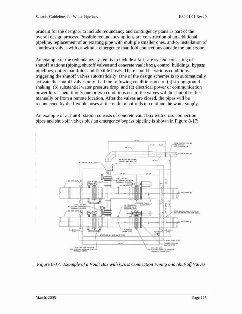
Seismic Guidelines for Water Pipelines R80.01.01 Rev. 0
March, 2005 Page 115
prudent for the designer to include redundancy and contingency plans as part of the overall design process. Possible redundancy options are construction of an additional pipeline, replacement of an existing pipe with multiple smaller ones, and/or installation of shutdown valves with or without emergency manifold connections outside the fault zone.
An example of the redundancy system is to include a fail-safe system consisting of shutoff stations (piping, shutoff valves and concrete vault box), control buildings, bypass pipelines, outlet manifolds and flexible hoses. There could be various conditions triggering the shutoff valves automatically. One of the design schemes is to automatically activate the shutoff valves only if all the following conditions occur: (a) strong ground shaking, (b) substantial water pressure drop, and (c) electrical power or communication power loss. Then, if only one or two conditions occur, the valves will be shut off either manually or from a remote location. After the valves are closed, the pipes will be reconnected by the flexible hoses at the outlet manifolds to continue the water supply.
An example of a shutoff station consists of concrete vault box with cross-connection pipes and shut-off valves plus an emergency bypass pipeline is shown in Figure 8-17:
Figure 8-17. Example of a Vault Box with Cross Connection Piping and Shut-off Valves
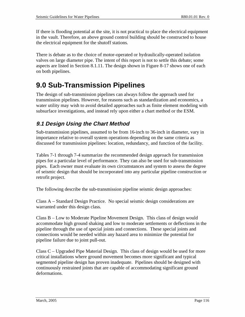
Seismic Guidelines for Water Pipelines R80.01.01 Rev. 0
March, 2005 Page 116
If there is flooding potential at the site, it is not practical to place the electrical equipment in the vault. Therefore, an above ground control building should be constructed to house the electrical equipment for the shutoff stations.
There is debate as to the choice of motor-operated or hydraulically-operated isolation valves on large diameter pipe. The intent of this report is not to settle this debate; some aspects are listed in Section 8.1.11. The design shown in Figure 8-17 shows one of each on both pipelines.
9.0 Sub-Transmission Pipelines The design of sub-transmission pipelines can always follow the approach used for transmission pipelines. However, for reasons such as standardization and economics, a water utility may wish to avoid detailed approaches such as finite element modeling with subsurface investigations, and instead rely upon either a chart method or the ESM.
9.1 Design Using the Chart Method Sub-transmission pipelines, assumed to be from 16-inch to 36-inch in diameter, vary in importance relative to overall system operations depending on the same criteria as discussed for transmission pipelines: location, redundancy, and function of the facility.
Tables 7-1 through 7-4 summarize the recommended design approach for transmission pipes for a particular level of performance. They can also be used for sub-transmission pipes. Each owner must evaluate its own circumstances and system to assess the degree of seismic design that should be incorporated into any particular pipeline construction or retrofit project.
The following describe the sub-transmission pipeline seismic design approaches:
Class A – Standard Design Practice. No special seismic design considerations are warranted under this design class. Class B – Low to Moderate Pipeline Movement Design. This class of design would accommodate high ground shaking and low to moderate settlements or deflections in the pipeline through the use of special joints and connections. These special joints and connections would be needed within any hazard area to minimize the potential for pipeline failure due to joint pull-out. Class C – Upgraded Pipe Material Design. This class of design would be used for more critical installations where ground movement becomes more significant and typical segmented pipeline design has proven inadequate. Pipelines should be designed with continuously restrained joints that are capable of accommodating significant ground deformations.
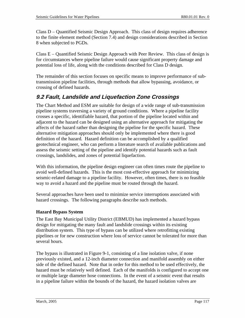
Seismic Guidelines for Water Pipelines R80.01.01 Rev. 0
March, 2005 Page 117
Class D – Quantified Seismic Design Approach. This class of design requires adherence to the finite element method (Section 7.4) and design considerations described in Section 8 when subjected to PGDs. Class E – Quantified Seismic Design Approach with Peer Review. This class of design is for circumstances where pipeline failure would cause significant property damage and potential loss of life, along with the conditions described for Class D design. The remainder of this section focuses on specific means to improve performance of sub-transmission pipeline facilities, through methods that allow bypassing, avoidance, or crossing of defined hazards.
9.2 Fault, Landslide and Liquefaction Zone Crossings The Chart Method and ESM are suitable for design of a wide range of sub-transmission pipeline systems traversing a variety of ground conditions. Where a pipeline facility crosses a specific, identifiable hazard, that portion of the pipeline located within and adjacent to the hazard can be designed using an alternative approach for mitigating the affects of the hazard rather than designing the pipeline for the specific hazard. These alternative mitigation approaches should only be implemented where there is good definition of the hazard. Hazard definition can be accomplished by a qualified geotechnical engineer, who can perform a literature search of available publications and assess the seismic setting of the pipeline and identify potential hazards such as fault crossings, landslides, and zones of potential liquefaction. With this information, the pipeline design engineer can often times route the pipeline to avoid well-defined hazards. This is the most cost-effective approach for minimizing seismic-related damage to a pipeline facility. However, often times, there is no feasible way to avoid a hazard and the pipeline must be routed through the hazard. Several approaches have been used to minimize service interruptions associated with hazard crossings. The following paragraphs describe such methods.
Hazard Bypass System
The East Bay Municipal Utility District (EBMUD) has implemented a hazard bypass design for mitigating the many fault and landslide crossings within its existing distribution system. This type of bypass can be utilized where retrofitting existing pipelines or for new construction where loss of service cannot be tolerated for more than several hours.
The bypass is illustrated in Figure 9-1, consisting of a line isolation valve, if none previously existed, and a 12-inch diameter connection and manifold assembly on either side of the defined hazard. Note that in order for this method to be used effectively, the hazard must be relatively well defined. Each of the manifolds is configured to accept one or multiple large diameter hose connections. In the event of a seismic event that results in a pipeline failure within the bounds of the hazard, the hazard isolation valves are
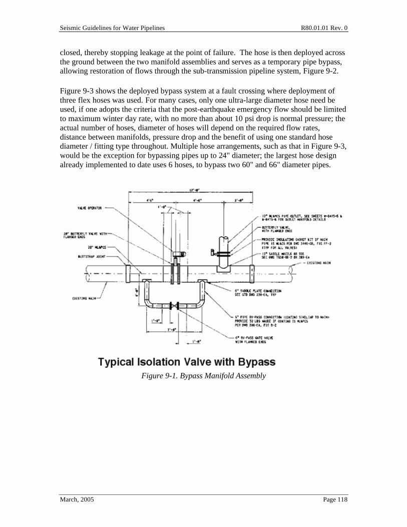
Seismic Guidelines for Water Pipelines R80.01.01 Rev. 0
March, 2005 Page 118
closed, thereby stopping leakage at the point of failure. The hose is then deployed across the ground between the two manifold assemblies and serves as a temporary pipe bypass, allowing restoration of flows through the sub-transmission pipeline system, Figure 9-2.
Figure 9-3 shows the deployed bypass system at a fault crossing where deployment of three flex hoses was used. For many cases, only one ultra-large diameter hose need be used, if one adopts the criteria that the post-earthquake emergency flow should be limited to maximum winter day rate, with no more than about 10 psi drop is normal pressure; the actual number of hoses, diameter of hoses will depend on the required flow rates, distance between manifolds, pressure drop and the benefit of using one standard hose diameter / fitting type throughout. Multiple hose arrangements, such as that in Figure 9-3, would be the exception for bypassing pipes up to 24" diameter; the largest hose design already implemented to date uses 6 hoses, to bypass two 60" and 66" diameter pipes.
Figure 9-1. Bypass Manifold Assembly
Seismic Guidelines for Water Pipelines R80.01.01 Rev. 0
March, 2005 Page 119
Figure 9-2. Hazard Bypass System – Deployed Hose Schematic
Figure 9-3. Flex Hose Attached to Manifold Outlets

Seismic Guidelines for Water Pipelines R80.01.01 Rev. 0
March, 2005 Page 120
Deployment of these hoses must be considered. Figures 9-4 and 9-5 show two types of deployment systems. The system in Figure 9-4 is preferred, as it allows for simpler storage of the hose when not is use.
Figure 9-4. Deployment Using Flaking Box
Figure 9-5. Deployment Using Hose Reel
9.2.1 Location of isolation valves for bypass relative to mapped hazard
The location of the hazard isolation valves is critical to the success of the bypass system. The pipeline engineer must work with the geotechnical engineer to identify low risk sites that have easy access and ample room for deployment of the hose and making of the connections. The Table 9-1 presents criteria for location of the hazard isolation valves.

Seismic Guidelines for Water Pipelines R80.01.01 Rev. 0
March, 2005 Page 121
Description Criteria Site location • Low seismic risk area and out of main hazard
• Easily accessible in emergency conditions by hose deployment vehicles
• Ample area for system deployment • Existing valve location, if appropriate
Hazard Isolation Valve • Existing or new • Buried with valved bypass • Valve size = pipe size • Butterfly valve AWWA C504, Class 150B, minimum
Table 9-1. Hazard Isolation Valve Minimum Criteria
9.2.2 Bypass System Components
The bypass system piping can consist of welded steel pipe, mortar-lined and mortar- or epoxy/tape-coated. The criteria for the bypass system components are included in Table 9-2. So called "large diameter flex hose" (diameter ~5-inch) will generally not provide sufficient flow rate at a reasonable pressure drop, for distances on the order of 1,000 feet between manifolds. So called "ultra large diameter flex hose" (diameter ~12-inch) can provide high flow rates at separation distances of 1,000 feet (or more). There are pros and cons with using either 5-inch or 12-inch hose, including: flow rate and pressure drop; cost; storage life; deployment effort and time; hose breakage and resultant pipe whip; etc.
Description Criteria Pipe Materials • Mortar-lined and mortar- or tape/epoxy-coated steel pipe (AWWA
C200) • Field joints should be flanged, welded, or mechanically coupled with
suitable restraint • Design for anticipated internal, external, and transient loading
conditions • Provide cathodic protection as needed
Manifold Hose Connection
• 12-inch grooved end steel pipe riser with grooved end 1/8 bend elbow and mechanical coupling adapter for hose fitting.
Manifold Pit • Precast reinforced concrete with seismic design factors suitable for site
• Traffic rated steel plate cover • Sized for easy hose deployment
12-inch Valves and Smaller
• Sized for easy hose deployment Butterfly (AWWA C504) or Gate (AWWA C509)
Flexible Hose • Super Aqueduct Fluid Delivery Hose by Kidde, Angus Flexible Pipelines Division, up to 12-inch diameter
• Typical burst pressure ~ 400 psi, operating pressure ~150 psi. Distances up to 1,000 feet or more at flow rates of up to 5,000 gpm.
• 5-inch fire hose from local Fire Department. Distances up to 1,000 feet at flow rates of up to 500 gpm
• Connections to be coordinated with manifold configuration
Table 9-2. Bypass System Components Criteria
9.2.3 Coating System Details
As with any part of a water conveyance system, proper coating and lining of pipe, valves, and appurtenances is important in achieving a long service life for the capital facilities.
Seismic Guidelines for Water Pipelines R80.01.01 Rev. 0
March, 2005 Page 122
Each owner must provide appropriate specifications and shop and field inspection to ensure that all metallic items are protected from corrosion. Cathodic protection of system components must be compatible with the cathodic protection of the sub-transmission system itself, if one exists. A qualified pipeline corrosion engineer can provide assistance and recommendations for cathodic protection and coating systems.
9.2.4 Purchase Specifications for Bypass System Components
Typically, these components would be standard AWWA-specified components, at a minimum, with additional requirements added by each owner to suit local requirements and practice.
9.2.5 Isolation Valve Approach Near Hazards
Another method for dealing with a hazard that cannot be avoided is similar to that described for the EBMUD-style bypass. The method consists of installing isolation valves at either edge of the hazard crossing, but without the manifold connections that would allow prompt bypassing of flow across the hazard. This method can be used where service disruptions can be accommodated because of redundant supply pipelines; and where the intent is to avoid de-pressurizing the remaining parts of the pipe network due to likely pipeline damage at the hazard location. In the event of a seismic event, the isolation valves near the hazard would be rapidly closed, isolating the pipeline failure from the rest of the system and thus maintaining pressures and flows in other non-damaged parts of the system. The owner would then mobilize repair crews to fix the damage and return the pipeline to service. This could take from several days to several weeks, depending on material and crew availability. In some cases, it would be prudent to stockpile spare pipe, valves, and accessories so that when an event occurs, the repair crews will have all the materials needed to put the pipeline back into service.
This approach works best for larger diameter (sub-transmission or larger) pipelines in a redundant network, and when the hazard is clearly located and clearly going to break the existing pipelines.
9.2.6 Automation of Isolation Valves
There are a few cases where automated isolation valves could be justified by an owner.
• Where isolation valves are in a remote, difficult to access location, the owner might consider automating the function of the hazard isolation valves. This could be as simple as providing for remote valve actuation capabilities or, if warranted by the particular consequences of an uncontrolled release of water, automating valve response based on local measurement of pressure or velocity/flow rate, possibly in combination with measured ground acceleration at the valve vault.
• When the impact of system depressurization is so critical that rapid isolation is needed (within several to tens of minutes) post earthquake.
Seismic Guidelines for Water Pipelines R80.01.01 Rev. 0
March, 2005 Page 123
• When the pipe failure at the hazard is likely to lead to major inundation losses, life safety impacts, erosion of nearby soils, or activation of other hazards (such as landslide).
Any automation or remote control capability for a valve would require installing an electric motor or hydraulic/pneumatic actuator on the valve. This requires a vault to house the valve and actuator. If electric motor actuator is used, a standby power source would be needed, such as a battery rack UPS system or a small generator and ATS. The hydraulic or pneumatic actuators would also require standby power, typically stored air in a receiver tank or backup power to the hydraulic pump. Other considerations include providing for multiple valve strokes to close, then open valve if system is undamaged.
9.3 Avoidance/Relocation of Sub-Transmission Pipeline Out of Hazard Area When feasible to do so, pipeline engineers should attempt to locate the pipeline facility away from fault, landslide, or potential liquefaction hazards. To do so could require considerable effort at defining the hazards. Examples of methods to avoid each of these hazards are described below.
9.3.1 Fault Crossings
Avoiding fault crossings assumes that the distribution system is not bisected by the fault or that the supply and distribution system are not separated by the fault. Avoidance strategies include rerouting away from the hazard. The hazard should be defined by a suitably qualified engineering geologist / geotechnical engineer so that routing options are clearly understood by the pipeline engineer. If the pipe must cross the fault, and the service criteria for the pipe is for the pipe to remain in service immediately post-earthquake, the common approach is to choose the pipe alignment so that the sense of fault movement will result in net tension in the pipe. If the pipe must cross the fault such that is will be put into compression (net of axial and bending strains), then careful attention should be placed to avoid endue amounts of wrinkling for steel pipe; for applications of pressure (100 psi to 150 psi) pipe up to about 24 inches in diameter, HDPE installations can provide good performance.
9.3.2 Landslides
Landslides are typically localized unstable slope areas that are readily identifiable based on geotechnical exploration or historic slide activity in the area. Landslides can be deep-seated or relatively shallow. Where a landslide is deep-seated, the pipeline engineer should look for ways around the landslide. However, if the slide is shallow, the pipeline engineer has the opportunity to install the pipeline beneath the slide plane using trenchless pipeline construction methods. Defining the slide plane is the critical criterion for establishing the depth of the pipeline. A qualified geotechnical engineer should assist in defining the base of the landslide. Exploratory borings will be required to analyze and establish the base of the slide plane.
Seismic Guidelines for Water Pipelines R80.01.01 Rev. 0
March, 2005 Page 124
9.3.3 Areas of Potential Liquefaction
Areas of potential liquefaction occur in loosely- to moderately-consolidated sandy and silty soils. Seismic ground shaking causes these soils to become “quick” and to temporarily lose their strength. Pipeline and other improvements in this kind of soil condition will lose their foundation support and likely fail if not properly designed for such conditions.
Because it is not feasible to accurately define the areal extent or relative vulnerability to seismically induced liquefaction, pipeline engineers often are not aware of areas of potential liquefaction along their proposed alignments. Where these areas have been defined to some extent, the pipeline engineer should attempt to locate critical facilities outside their influence. Where a pipeline must cross areas of potential liquefaction, the pipeline engineer could consider some in-place soil densification methods to densify the silty and sandy soils, making them less prone to liquefaction. This is a costly and disruptive process that would be most feasible in undeveloped areas with suspect soils near-surface.
9.4 Liquefaction Induced Settlement Liquefaction-induced settlement has been proven to damage many types of buried pipeline infrastructure. Where liquefaction is present, the pipeline must be able to span the area of liquefaction without pull-out at joints. A moderate amount of settlement can be accommodated using semi-restrained or unrestrained push-on (bell and spigot) type joints.
9.4.1 Accommodating Settlements Using Semi-Restrained and Unrestrained Pipe
Semi restrained joints include ductile iron pipe proprietary joints that rely on mechanical clamping to the pipe spigot for resistance to axial loads. Unrestrained joints include any kind of push-on rubber gasket bell and spigot type joint. These kinds of joints can accommodate some degree of joint deflection and joint pull-out prior to joint opening and subsequent failure of the joint. For locations with predicted settlements less than 12 inches transverse to the pipe, the Chart Method (Tables 7-2, 7-6) allows the use of unrestrained pipe for some pipe that requires seismic design. While the Chart Method allows unrestrained pipe for transverse movement, this requires the designer to be confident that the sense of the PGD will only be transverse to the axis of the pipe (such as settlement), and assumes that the PGD profile is quite gradual over the length of the pipe (i.e., not a sharp offset).
9.4.2 Accommodating Settlements using Butt Welded Steel Pipe and Butt Fused HDPE Pipe
Where the pipeline engineer and geotechnical engineer have estimated large ground settlements, segmented piping systems are less desired. Continuous pipelines are often used in these situations. Examples of this kind of system are butt-welded steel pipe and butt-fused high density polyethylene (HDPE) pipe. Each of these pipe systems is constructed to be one continuous section of pipe with the field joints achieving same or
Seismic Guidelines for Water Pipelines R80.01.01 Rev. 0
March, 2005 Page 125
better strength than the main pipe and without introducing stress concentrators such as flange connections.
The properties of steel and HDPE pipe materials provide for a ductile and flexible pipe installation that is capable of self-supporting over some distance. Butt welded steel pipe is used extensively in the petroleum and natural gas industries, though little used in the U.S. municipal industry. HDPE is becoming more popular with many municipal agencies for its chemical inertness and flexibility under a range of ground conditions.
9.5 Specialized Fittings and Connections Many special fittings and connections are available for a wide variety of pipe materials. Several of these special fittings have been designed with differential movement in mind. The application of these special fittings and connections must be specific to a specific set of conditions facing the pipeline engineer. For instance, when transitioning from a rigid structure to a buried pipeline installation, some means must be introduced to accommodate differential settlements and dissimilar responses to seismic ground shaking and movement.
The following special fittings and connections can be utilized by the pipeline engineer to provide for flexibility and to accommodate significant movement of the pipeline. These are further discussed in the following paragraphs.
• EBAA-Iron Flex-Tend Joint – provides for vertical and horizontal deflection and axial compression and expansion.
• Sleeve-Type Mechanical Couplings – provides for limited vertical and horizontal deflection.
• Bellows-type Expansion Joints – provides for axial, offset, and angular deflections
• Sleeve-type Expansion Joints – provides for axial expansion and contraction.
• Japanese Seismic Joint – provides for angular deflection in ductile iron pipe systems.
Table 9-3 is a summary of typical applications for these specialty fittings, along with selected information on the cost of the materials.

Seismic Guidelines for Water Pipelines R80.01.01 Rev. 0
March, 2005 Page 126
Connection/Joint Type and Unit Cost1
Application
Flex-Tend (Double Ball with One Sleeve)
Sleeve-Type Coupling
Bellows Expansion Joint
Sleeve-Type Expansion Joint
Japanese Seismic Joint
36-inch @ $46k 24-inch @ $12k 18-inch @ $8k
36-inch @ $2k 24-inch @ $1.5k 18-inch @ $1k
36-inch @ $7k 24-inch @ $5k 18-inch @ $3k
PGD axial up to 12 inches, sharp application
Very Good Good for PGD up to a few inches
Good for PGD up to a few inches
Good Uncertain, likely good
PGD axial over 12 inches, sharp application
Uncertain, possibly good
Not Good Not Good Good Uncertain, possibly good
PGD transverse up to 12 inches, gradual application
Very Good in string
Good for PGD up to ~2-6 inches
Good for PGD up to ~6 inches
Possibly adequate in combination w/ angular deflection joint
Very Good
PGD transverse over 12 inches, gradual application
Marginal, better in string
Not Good Uncertain Uncertain Uncertain, likely adequate
Notes: 1. Costs based on basic configuration for materials only as quoted from manufacturers in December 2004. Consult manufacturers for specific application and needs. PGD ratings are approximate and will vary based on pipe diameter and connection configuration.
Table 9-3. Summary of Special Fittings and Connections for Sub-Transmission Pipelines
Flex-Tend Joint (as manufactured by EBAA Iron)
The Flex-Tend flexible expansion joint accommodates loads on a pipeline caused by sudden or gradual differential movement associated with seismic ground shaking and permanent ground deformation. The Flex-Tend is designed to achieve up to 20 degrees of rotational movement per ball (15-degrees for moderate diameter, 10-degrees very large diameter) and a capability to configure multiple balls in a single pipe string. Multiple expansion/contraction elements can be strung together between the ball joints to achieve a desired set of design criteria. As the rotation occurs, the Flex-Tend is able to expand or contract to relieve axial stresses in the pipeline. Figure 9-6 is an illustration of a typical Flex-Tend assembly.
The Flex Tend is available in sizes from 3-inch to 48-inch in diameter and can be installed in ductile iron, steel, and PVC pipe systems. The standard design is rated up to 350-psi working pressure in sizes up to and including 24-inch, and 250-psi for sizes 30-inch and larger. The Flex-Tend is available with flanged or mechanical joint ends. Section 12.1 provides some design considerations for use of Flex-Tend joints for fault offset application.
The typical application includes structure-to-soil transitions (particularly unanchored steel water tanks with side entry pipes that enter the ground). Another good application is

Seismic Guidelines for Water Pipelines R80.01.01 Rev. 0
March, 2005 Page 127
for areas of significant soil settlements. Application of this component at fault crossings where PGD is several feet or more, can be accomplished, bit only with a string of components (depending on pipe diameter); if the fault zone is wide and the location of offset uncertain, installation of just a single such component may not afford adequate protection; the performance of the straight pipe and slip joint between the ball joints should be assessed in consideration of restrained soil conditions.
Test of the component is typically to a design pressure. Test and performance data for application to failure due to imposed PGD in buried conditions is typically not available in the manufacturer's catalogs; it is uncertain what the performance of the component will be if loaded to beyond its rotation / axial slip capacity, as to whether the component will pull apart, or suitably transfer the load to adjacent pipe.
Figure 9-6. Flex-Tend Joint (Courtesy of EBAA Iron)
Sleeve-Type Mechanical Couplings (AWWA C219)
Sleeve couplings are available from a number of manufacturers and are commonly used in the water industry. The sleeve-type coupling is shown in Figure 9-7 and consists of a steel sleeve (middle ring) that fits over the plain ends of the connecting pipes, two follower rings (end rings) that slide onto the pipe ends, o-ring rubber gaskets that seal between the pipe, the steel sleeve, and the follower rings, and threaded bolts and nuts that are used to bring the follower rings into the sleeve, exerting a clamping force through the gasket and onto the pipe ends. This is not a restrained joint and requires suitable anchorage to prevent pipe pullout when in axial tension. The coupling can accommodate a small amount of axial separation of the pipe ends and is typically installed with a small gap between the pipe ends. Typical application of sleeve-type couplings is to transition from one pipe material to another, transition different pipe outside diameters, provide some small amount of flexibility in structure to soil transitions, and to connect plain ends of pipe.

Seismic Guidelines for Water Pipelines R80.01.01 Rev. 0
March, 2005 Page 128
Sleeve type couplings are available in sizes from -inch and larger and with sleeve lengths of 3.5 inches to 10 inches. They can accommodate angular deflection up to four degrees, depending on length of the steel sleeve and diameter of the coupling and pipe. The basic manufacture and installation of sleeve-type mechanical couplings is defined by AWWA C219.
For PGDs along the axis of the pipe, the sleeve joint can accommodate the movement up to the design capacity of the sleeve. If the location of the PGD is uncertain, then every joint that might have imposed PGD should be designed to accommodate the full PGD.
Figure 9-7. Sleeve-Type Coupling (Courtesy AWWA)
Bellows-Type Expansion Joints (EJMA Standards, 8th Edition)
Bellows-type expansion joints are available from a number of manufacturers and are typically used for thermal expansion and contraction control in industrial applications. Water industry use is limited. The bellows-type coupling is shown in Figure 9-8 and consists of a stainless steel bellows tube with either flanged or butt weld ends. The bellows acts to allow relative movement of the connecting pipe ends while maintaining the pressure integrity of the joint. This is not a restrained joint and requires suitable anchorage to prevent over-deflection or extension/contraction. Typical application of

Seismic Guidelines for Water Pipelines R80.01.01 Rev. 0
March, 2005 Page 129
bellows-type couplings is to accommodate pipe movement associated with thermal loadings.
Bellows type couplings are available in sizes from 2-inch to 24-inch up to a pressure rating of 300-psi. Larger sizes are available but only at low (less than 50-psi) pressure ratings. Individual bellows couplings can accommodate axial movement of up to 1.8 inches and lateral offset of up to 0.1 inches. The basic manufacture and installation of sleeve-type mechanical couplings is defined by the standards of the Expansion Joint Manufacturer’s Association (EJMA).
Table 9-8. Bellows-Type Expansion Joint (Courtesy Flexicraft)
Sleeve-type Expansion Joints (AWWA C221)
Fabricated steel mechanical slip-type expansion joints are available from a number of manufacturers and are commonly used in the water industry to accommodate expansion and contraction of more than 0.5 inches. The sleeve-type expansion joint is shown in Figure 9-9 and consists of a steel slip pipe, body, gland, packing chamber with alternate rings of elastomeric material and lubricating rings, and follower ring. A limit ring and limit rods to limit overall expansion/contraction movement. Threaded fasteners are used to tighten the follower ring and gland, which compresses the packing to make a watertight seal. This is not a restrained joint and requires suitable anchorage to prevent pipe pullout when in axial tension. This joint also requires access for maintenance. Typical application of sleeve-type expansion joint is to accommodate greater than 0.5 inches of axial movement.
Sleeve type expansion joints are available in sizes from 3-inch to 24-inch standard, with larger sizes custom engineered by the manufacturer. They can accommodate up to 5 inches of axial movement, 10 inches when in a double configuration. Additional movement can be accommodated by putting units in series; the limit rods and attached pipe must be strong enough to transfer imposed soil loading to the adjacent expansion joint. The pressure rating of the expansion joint is defined by the purchaser and can be
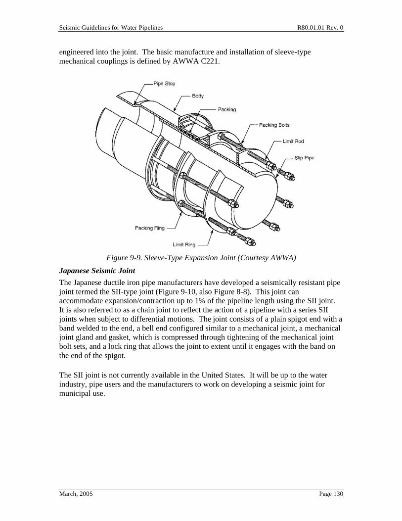
Seismic Guidelines for Water Pipelines R80.01.01 Rev. 0
March, 2005 Page 130
engineered into the joint. The basic manufacture and installation of sleeve-type mechanical couplings is defined by AWWA C221.
Figure 9-9. Sleeve-Type Expansion Joint (Courtesy AWWA)
Japanese Seismic Joint
The Japanese ductile iron pipe manufacturers have developed a seismically resistant pipe joint termed the SII-type joint (Figure 9-10, also Figure 8-8). This joint can accommodate expansion/contraction up to 1% of the pipeline length using the SII joint. It is also referred to as a chain joint to reflect the action of a pipeline with a series SII joints when subject to differential motions. The joint consists of a plain spigot end with a band welded to the end, a bell end configured similar to a mechanical joint, a mechanical joint gland and gasket, which is compressed through tightening of the mechanical joint bolt sets, and a lock ring that allows the joint to extent until it engages with the band on the end of the spigot.
The SII joint is not currently available in the United States. It will be up to the water industry, pipe users and the manufacturers to work on developing a seismic joint for municipal use.

Seismic Guidelines for Water Pipelines R80.01.01 Rev. 0
March, 2005 Page 131
Figure 9-10. Japanese SII Joint
TerraBrute Joint
The TerraBrute1 joint is a chain-type joint configured for use with C900 PVC pipe (Figure 9-11). In concept, the joint allows some amount of axial movement of the adjacent PVC pipes, before the steel rings stop against a steel insert piece. For corrosion resistance, the manufacturer reports that the steel ring and pins shown in Figure 9-11 may be replaced with polyurethane rings and stainless steel or nylon pins. Tests of this type of joint are being made by the manufacturer as of early 2005.
Figure 9-11. TerraBrute Joint
1 Courtesy Ipex, www.ipexinc.com
Seismic Guidelines for Water Pipelines R80.01.01 Rev. 0
March, 2005 Page 132
10.0 Distribution Pipelines The two most common types of pipelines used in new water pipe installations in the United States are polyvinyl chloride (PVC) and ductile iron (DI) pipes. The most common joint used in these installations (and the least expensive) is the "push-on" rubber gasketed joint. PVC pipe is relatively cheap, and is corrosion resistant. Contrary to some claims made by manufacturers, DI installations of this type have not proved to be "seismically invulnerable", as evidenced in the 1994 Northridge and 1995 Kobe earthquakes. Further, DI may be corrosion sensitive, unlike less expensive PVC materials. The DI manufacturers have responded by employing polyethylene external liners, but some owners remain skeptical than pin holes in the liners will lead to permanent damp environments, leading to more rapid corrosion than otherwise. This is not to say that PVC pipe is ideal, in that any significant bending on the pipe will often lead to tensile rupture (split), with break more common than leak.
Given these issues, the Guidelines describe alternative installations, as follows:
• Standard installation (per AWWA standards) (least expensive)
• Enhanced throw joint installation (longer travel available at gasketed joints)
• Lock-type joints (inserted binders that prevent pull apart, after the pipe is installed)
• Mechanical joints (friction-gland systems)
• Semi-restrained joints (similar to Japanese S-II type joints), which allow some axial pull and some rotation at each joint (most expensive).
The Guidelines consider relative costs for each installation; recommended range limits for ground velocity and ground deformation for each joint. As of early 2005, manufacturer's catalogs often do not include sufficient engineering data (pull out strengths, stiffnesses) to validate engineering design assumptions required when using either the ESM or FEM methods. The chart method recommendation infer certain capacities for the joints, but are still largely based on engineering judgment. It is intended that pipe manufacturer's supply more quantified information about their products, so that cost-effective and optimal design strategies can be implemented.
The images of pipe joints in this chapter were adopted from a test program for pipe joints by Meis, Maragakis and Siddharthan (2003). The images are of test assemblies (prior to test) for common size 4" to 12" CI, DI, PVC and PE pipes.
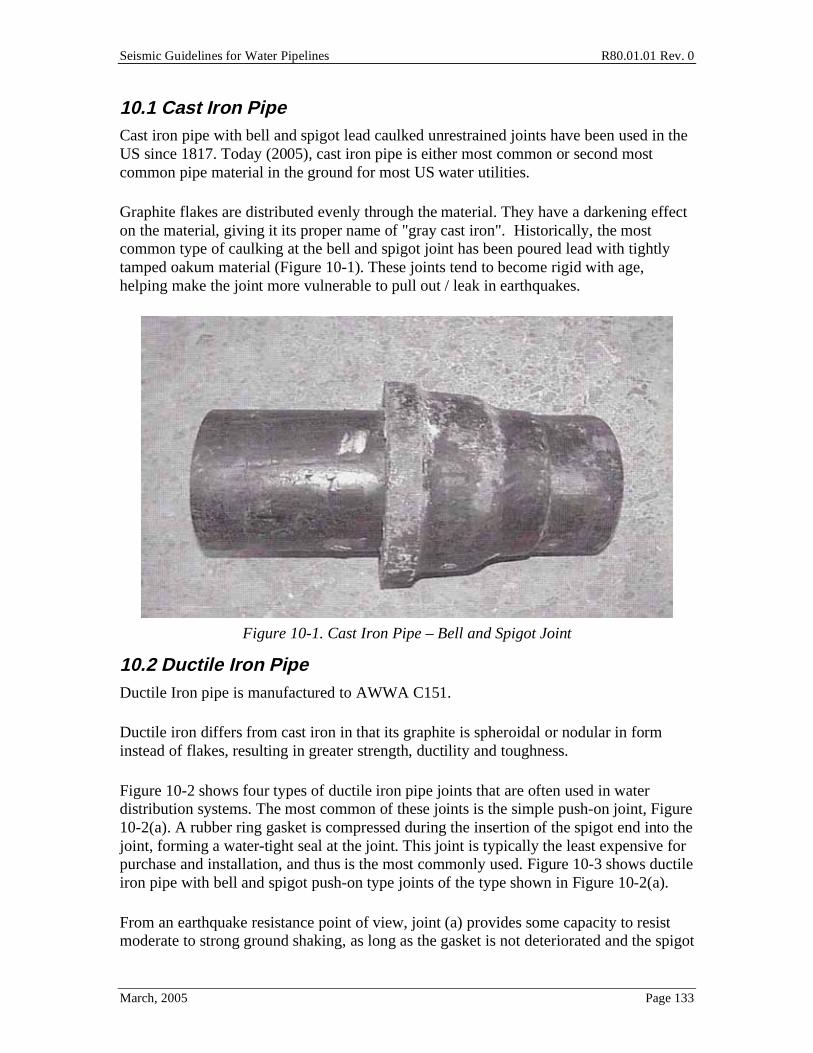
Seismic Guidelines for Water Pipelines R80.01.01 Rev. 0
March, 2005 Page 133
10.1 Cast Iron Pipe Cast iron pipe with bell and spigot lead caulked unrestrained joints have been used in the US since 1817. Today (2005), cast iron pipe is either most common or second most common pipe material in the ground for most US water utilities.
Graphite flakes are distributed evenly through the material. They have a darkening effect on the material, giving it its proper name of "gray cast iron". Historically, the most common type of caulking at the bell and spigot joint has been poured lead with tightly tamped oakum material (Figure 10-1). These joints tend to become rigid with age, helping make the joint more vulnerable to pull out / leak in earthquakes.
Figure 10-1. Cast Iron Pipe – Bell and Spigot Joint
10.2 Ductile Iron Pipe Ductile Iron pipe is manufactured to AWWA C151.
Ductile iron differs from cast iron in that its graphite is spheroidal or nodular in form instead of flakes, resulting in greater strength, ductility and toughness.
Figure 10-2 shows four types of ductile iron pipe joints that are often used in water distribution systems. The most common of these joints is the simple push-on joint, Figure 10-2(a). A rubber ring gasket is compressed during the insertion of the spigot end into the joint, forming a water-tight seal at the joint. This joint is typically the least expensive for purchase and installation, and thus is the most commonly used. Figure 10-3 shows ductile iron pipe with bell and spigot push-on type joints of the type shown in Figure 10-2(a).
From an earthquake resistance point of view, joint (a) provides some capacity to resist moderate to strong ground shaking, as long as the gasket is not deteriorated and the spigot
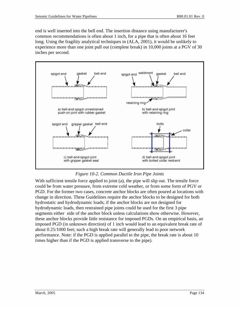
Seismic Guidelines for Water Pipelines R80.01.01 Rev. 0
March, 2005 Page 134
end is well inserted into the bell end. The insertion distance using manufacturer's common recommendations is often about 1 inch, for a pipe that is often about 16 feet long. Using the fragility analytical techniques in (ALA, 2001), it would be unlikely to experience more than one joint pull out (complete break) in 10,000 joints at a PGV of 30 inches per second.
Figure 10-2. Common Ductile Iron Pipe Joints
With sufficient tensile force applied to joint (a), the pipe will slip out. The tensile force could be from water pressure, from extreme cold weather, or from some form of PGV or PGD. For the former two cases, concrete anchor blocks are often poured at locations with change in direction. These Guidelines require the anchor blocks to be designed for both hydrostatic and hydrodynamic loads; if the anchor blocks are not designed for hydrodynamic loads, then restrained pipe joints could be used for the first 3 pipe segments either side of the anchor block unless calculations show otherwise. However, these anchor blocks provide little resistance for imposed PGDs. On an empirical basis, an imposed PGD (in unknown direction) of 1 inch would lead to an equivalent break rate of about 0.25/1000 feet; such a high break rate will generally lead to poor network performance. Note: if the PGD is applied parallel to the pipe, the break rate is about 10 times higher than if the PGD is applied transverse to the pipe).
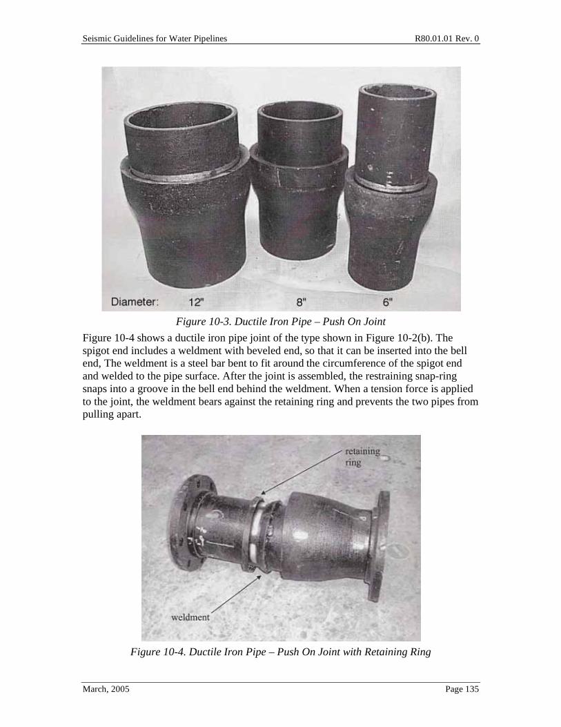
Seismic Guidelines for Water Pipelines R80.01.01 Rev. 0
March, 2005 Page 135
Figure 10-3. Ductile Iron Pipe – Push On Joint
Figure 10-4 shows a ductile iron pipe joint of the type shown in Figure 10-2(b). The spigot end includes a weldment with beveled end, so that it can be inserted into the bell end, The weldment is a steel bar bent to fit around the circumference of the spigot end and welded to the pipe surface. After the joint is assembled, the restraining snap-ring snaps into a groove in the bell end behind the weldment. When a tension force is applied to the joint, the weldment bears against the retaining ring and prevents the two pipes from pulling apart.
Figure 10-4. Ductile Iron Pipe – Push On Joint with Retaining Ring
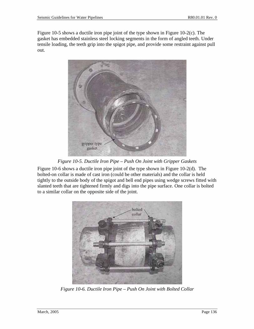
Seismic Guidelines for Water Pipelines R80.01.01 Rev. 0
March, 2005 Page 136
Figure 10-5 shows a ductile iron pipe joint of the type shown in Figure 10-2(c). The gasket has embedded stainless steel locking segments in the form of angled teeth. Under tensile loading, the teeth grip into the spigot pipe, and provide some restraint against pull out.
Figure 10-5. Ductile Iron Pipe – Push On Joint with Gripper Gaskets
Figure 10-6 shows a ductile iron pipe joint of the type shown in Figure 10-2(d). The bolted-on collar is made of cast iron (could be other materials) and the collar is held tightly to the outside body of the spigot and bell end pipes using wedge screws fitted with slanted teeth that are tightened firmly and digs into the pipe surface. One collar is bolted to a similar collar on the opposite side of the joint.
Figure 10-6. Ductile Iron Pipe – Push On Joint with Bolted Collar

Seismic Guidelines for Water Pipelines R80.01.01 Rev. 0
March, 2005 Page 137
10.3 PVC Pipe PVC pipe is a common pipe material now in use by water utilities in the US. It is manufactured to AWWA C900. Relative to DI pipe, it is lower weight, and hence somewhat easier to handle. Figure 10-7 shows a PVC pipe joint using a push-on connection.
Figure 10-7. PVC Pipe with Push On Joint
The discussion in C10.2 about fragility and break rate for DI pipe also applies for PVC pipe for wave propagation. In other words, push-on jointed PVC pipe should provide about the same level of performance as DI pipe when subjected to ground shaking. for locations where PVC pipe might be subject to PGDs, then push-on jointed PVC pipe will likely perform worse.
In areas subject to modest PGDs, PVC pipe with push-on joints can be installed with extra pipe insertion length, making for a simple "extended joint". The procedures in Section 7 can be used to estimate the required insertion length for every joint in the zone subject to PGD. Care should be taken to ensure that excessive joint rotation does not cause a split in the pipe. Restrained joints of similar types to those in Figure 10-2 are available; a joint capable of "chained" performance is described in Section 9.5.

Seismic Guidelines for Water Pipelines R80.01.01 Rev. 0
March, 2005 Page 138
10.4 High Density Polyethylene Pipe HDPE pipe is a newer pipe material now in limited use by water utilities in the US. It is manufactured to AWWA C906. HDPE is made from high density extra high molecular weight materials. HDPE pipe is commonly used for natural gas distribution lines, and sometimes for potable water pipes. Unlined HDPE pipe should not be used through contaminated soils.
The joints between segments of pipe are created by placing an elevated temperature metal plate between two pipe segments held within a clamping assembly, thus melting the plastic, and then removing the metal plate and forcing the two melted ends together. The finished joint is often called a fusion butt weld. Beads of plastic form outside and inside the pipe at the joint location.
Figure 10-7 shows a HDPE pipe with three butt welded fusion joints.
Figure 10-8. PE Pipe with Three Fusion Butt Welded Joints
10.5 Performance of Common Pipe Joints Under Axial Loads One of observed the failure mechanisms of water distribution pipes in earthquakes is the crushing (relatively rare) or pull out (more common) of pipe joints. In order to select an appropriate pipe joint for a particular pipeline installation application, the user should understand the failure mechanism.

Seismic Guidelines for Water Pipelines R80.01.01 Rev. 0
March, 2005 Page 139
While there have been many instances of pipe damage in earthquakes, it is often difficult to get accurate descriptions of the failure modes. To provide failure mechanisms under a controlled environment, Meis et al (2003) have taken typical distribution pipes and broken them in the lab.
Figure 10-9. Ductile Iron Pipe Cross Section (After Failure)
Figure 10-9 shows the failure mode for a 8-inch ductile iron joint (push-on type) under compression loading. The figure shows the failed specimen, cut in half to expose the joint. The failure is the wrinkling of the spigot pipe as it bears against the inside of the bell end. With sufficient wrinkling, the spigot end tears, and the space that holds the rubber gasket gets enlarged, end eventually the pipe leaks.
The following are some observations about the failure modes (from test):
• For DI pipe, compression failure occurs at displacements of about 0.4 cm, and always at 0.8 cm.
• For CI pipe, compression failure occurs at displacements of about 2.5 cm. CI typically can resist double the load than comparable diameter DI pipe.
• For DI pipe with joint type c (gripper teeth), tension failure occurs at pull-out displacements ranging from 1.5 cm (12-inch pipe) to 4-5 cm (6-inch to 8-inch pipe)
10.6 Seismic Design Recommendations for Distribution Pipelines Distribution systems must blanket the service area wherever development exists. As such, avoidance of larger hazards is not feasible and therefore distribution systems must
Seismic Guidelines for Water Pipelines R80.01.01 Rev. 0
March, 2005 Page 140
cross hazards. Because of the high degree of redundancy in a distribution system, through looping and multiple supply points, distribution systems can be isolated at points of damage and service restored outside the hazard area in relatively short order. Within the hazard area, damage may be so extensive that repairs will take time and full service will be slow to return. Using the concept presented in Section 9.0 for bypassing flow around damage zones, owners can establish temporary services using fire hoses connected to hydrants and isolation valves to serve undamaged areas or initially repaired areas.
Distribution pipelines are assumed to be less than 16-inch in diameter. Tables 7-5 through 7-19 summarize the recommended design approach for distribution pipeline facilities for a particular level of performance. The following describe the distribution pipeline seismic design approaches:
Class A – Standard Design Practice. No special seismic design considerations are warranted under this design class. Where additional valves are noted, the requirement would be for isolation valves to effectively isolate the hazard area from non-hazard areas and provide enough flexibility in bringing service back into hazard areas as repairs progress.
Class B – Restrained Joint Design. This class of design would accommodate low to moderate settlements or deflections in the pipeline through the use of restrained joints and connections, which would be needed within any hazard area to minimize the potential for pipeline failure due to joint pull-out. Provide additional valves (generally under 500-foot spacing, 4 valves at 4-way crossings, 3 valves at tees, adjacent to each hazard zone, etc.)
Class C – Upgraded Pipe Material Design. This class of design would be used for more critical installations where ground movement becomes more significant and typical segmented pipeline design has proven inadequate. Pipelines can be designed with ductile welded steel pipe or HDPE pipe, which would have continuously restrained joints that are capable of accommodating significant ground deformations. Restrained joint PVC and ductile iron pipe may be appropriate, augmented by enhanced-throw joints, lock ring joints, or other means that prevent pipe pull-out with ground motion and deformation.
Class D – Quantified Seismic Design Approach. This class of design requires adherence to the methodology and approach described in Section 7.4. This class of design is reserved for critical distribution facilities and high risk hazard conditions. The design may ultimately be similar to Class C, but with increased knowledge of the extent of the geotechnical hazard and the PGV and PGD demands on the pipe and pipe joints. Bypass systems (flex hose with valves) may be a suitable alternative.
10.7 Standard Installation Based on AWWA Guidelines In most areas of the United States, standard practice for installation of new distribution system pipelines relies primarily on PVC or DI pipe. A few utilities use other materials,
Seismic Guidelines for Water Pipelines R80.01.01 Rev. 0
March, 2005 Page 141
such as welded steel pipe (in high seismic hazard areas), and HDPE pipe (limited usage since mid 1990s, used in high PGD hazard areas).
The standard of practice for PVC and DI materials is described in good detail in AWWA Manual 23: PVC Pipe – Design and Installation and AWWA Manual 41: Ductile-Iron Pipe and Fittings. These publications define the methodology and approach for design of pipe systems for the respective materials. Owners should refer to these publications when undertaking design of distribution system projects using these two materials.
Both PVC and DI pipe design typically utilizes push-on rubber gasketed joints, except at fittings and valves. This type of design is appropriate, even for high ground shaking hazard areas, as long as good soils and geology exist (low chance for PGDs).
Where soils and geology are not favorable, the Guidelines suggest that some form of extended or restrained joints be used with DI or PVC pipe. Alternatively, welded steel pipe or HDPE pipe can be used, both exhibiting superior resistance to pull-out due to welded or fused joints, which creates continuous pipe (not segmented) construction. Alternatively, bypass systems might be installed.
Welded steel pipe is another common distribution system material. When constructed using welded joints, this material can provide good resistance to seismically induced ground motion and permanent ground deformations. Smaller diameter steel pipe (generally 20-inch and smaller) must use only single lap welded joints, as it is near impossible to fillet weld from the inside. Single lap-welds are not sufficiently ductile to withstand settlements much over 12 inches (perpendicular to the pipe) or 2 to 3 inches (parallel to the pipe). Double lap-welded pipe joints (generally impractical for smaller diameter pipe) are much better for ductility than single-lap welded pipe. Use of butt-welded joints provides a major increment of strength and ductility to withstand substantial amounts of ground movement transverse and parallel to the pipe. The standard of practice for welded steel pipe is described in good detail in AWWA Manual 11. Manual 11 does not suitably cover seismic loading.
For HDPE pipe, AWWA publishes a standard specification, AWWA C906 – AWWA Standard for Polyethylene (PE) Pressure Pipe and Fittings, 4-inch (100 mm) through 63-inch (1,575 mm), for Water Distribution and Transmission. This specification describes the material and workmanship requirements for HDPE pipe. Each manufacturer has a standard design and installation manual that owners should refer to when undertaking design of an HDPE pipeline.
As noted in Tables 7-5 through 7-8, improved system performance (post seismic event) can be achieved through use of distribution system redundancy and strategically located isolation valves that allow the system to be brought back into service after isolating out the damaged areas after the seismic event.
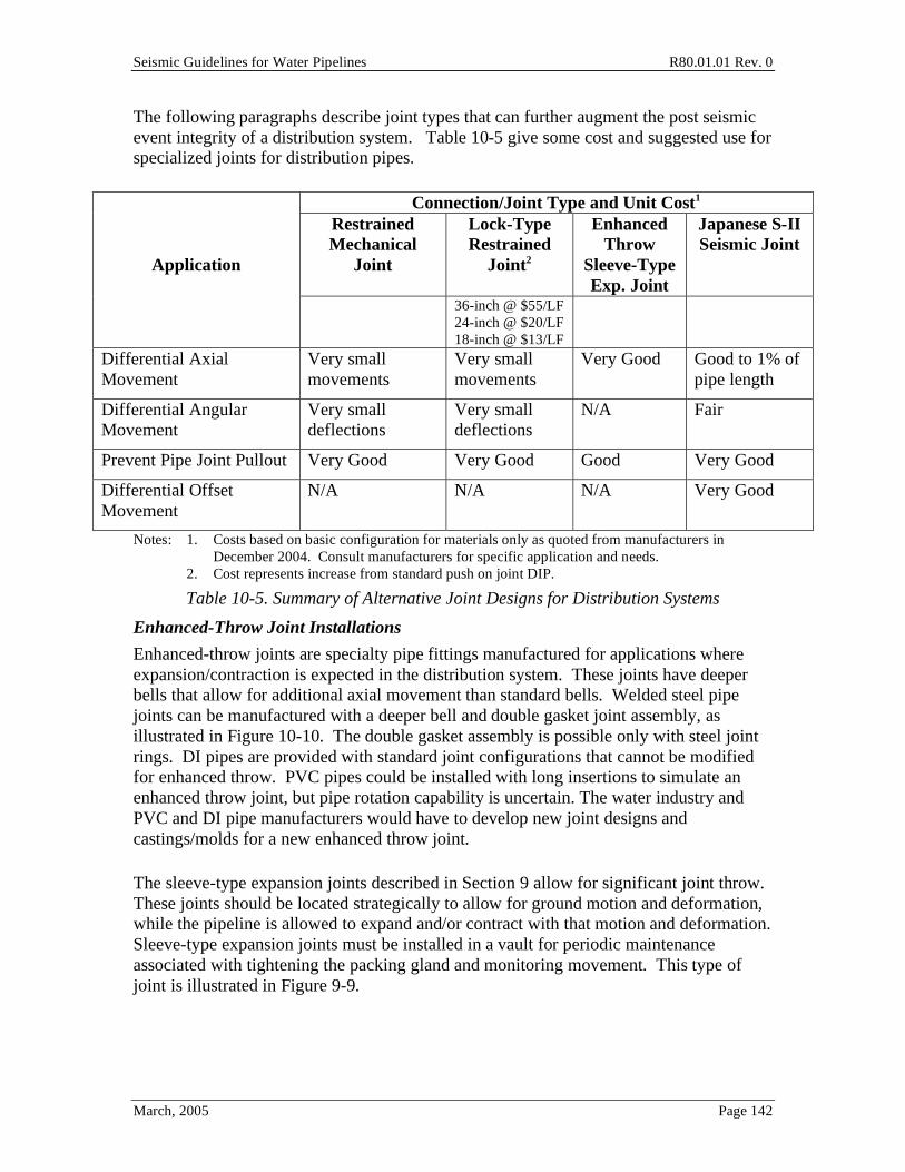
Seismic Guidelines for Water Pipelines R80.01.01 Rev. 0
March, 2005 Page 142
The following paragraphs describe joint types that can further augment the post seismic event integrity of a distribution system. Table 10-5 give some cost and suggested use for specialized joints for distribution pipes.
Connection/Joint Type and Unit Cost1
Application
Restrained Mechanical
Joint
Lock-Type Restrained
Joint2
Enhanced Throw
Sleeve-Type Exp. Joint
Japanese S-II Seismic Joint
36-inch @ $55/LF 24-inch @ $20/LF 18-inch @ $13/LF
Differential Axial Movement
Very small movements
Very small movements
Very Good Good to 1% of pipe length
Differential Angular Movement
Very small deflections
Very small deflections
N/A Fair
Prevent Pipe Joint Pullout Very Good Very Good Good Very Good
Differential Offset Movement
N/A N/A N/A Very Good
Notes: 1. Costs based on basic configuration for materials only as quoted from manufacturers in December 2004. Consult manufacturers for specific application and needs.
2. Cost represents increase from standard push on joint DIP.
Table 10-5. Summary of Alternative Joint Designs for Distribution Systems
Enhanced-Throw Joint Installations
Enhanced-throw joints are specialty pipe fittings manufactured for applications where expansion/contraction is expected in the distribution system. These joints have deeper bells that allow for additional axial movement than standard bells. Welded steel pipe joints can be manufactured with a deeper bell and double gasket joint assembly, as illustrated in Figure 10-10. The double gasket assembly is possible only with steel joint rings. DI pipes are provided with standard joint configurations that cannot be modified for enhanced throw. PVC pipes could be installed with long insertions to simulate an enhanced throw joint, but pipe rotation capability is uncertain. The water industry and PVC and DI pipe manufacturers would have to develop new joint designs and castings/molds for a new enhanced throw joint.
The sleeve-type expansion joints described in Section 9 allow for significant joint throw. These joints should be located strategically to allow for ground motion and deformation, while the pipeline is allowed to expand and/or contract with that motion and deformation. Sleeve-type expansion joints must be installed in a vault for periodic maintenance associated with tightening the packing gland and monitoring movement. This type of joint is illustrated in Figure 9-9.
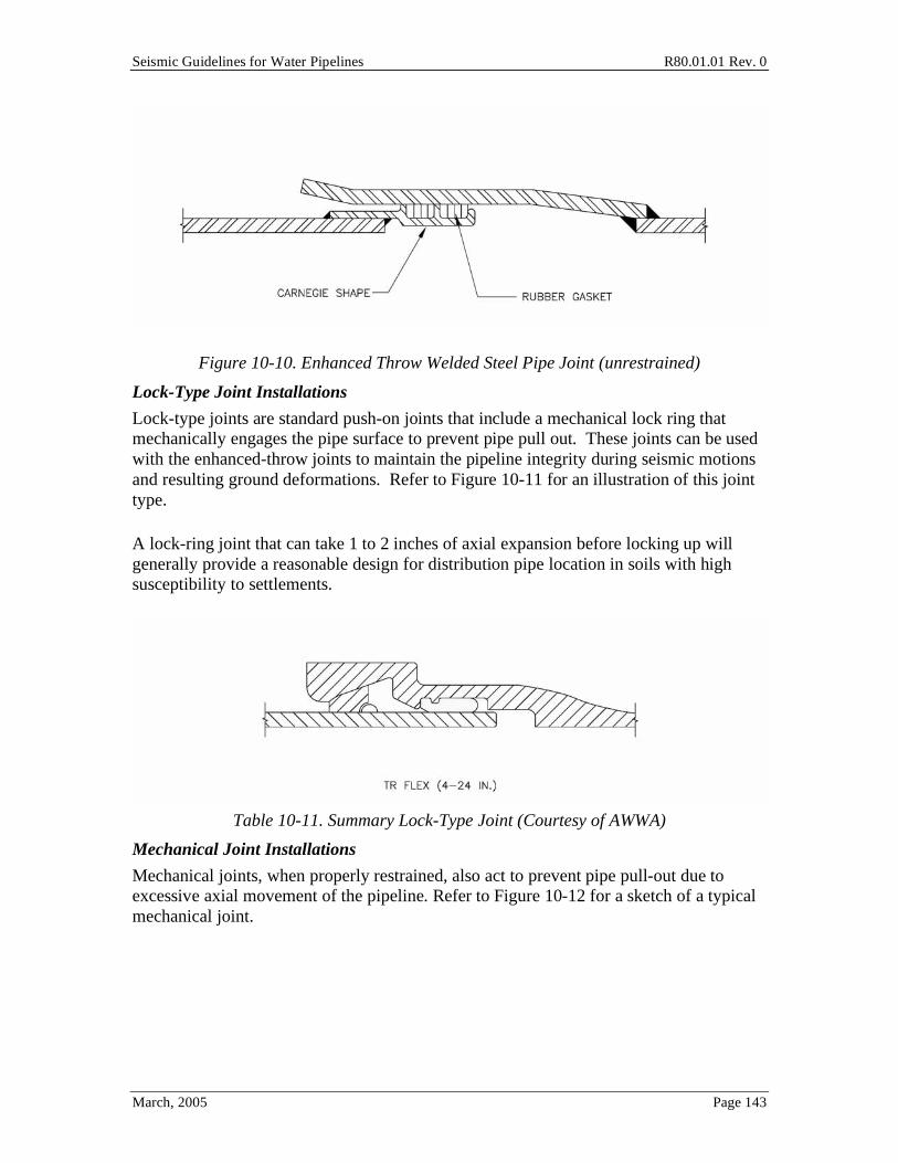
Seismic Guidelines for Water Pipelines R80.01.01 Rev. 0
March, 2005 Page 143
Figure 10-10. Enhanced Throw Welded Steel Pipe Joint (unrestrained)
Lock-Type Joint Installations
Lock-type joints are standard push-on joints that include a mechanical lock ring that mechanically engages the pipe surface to prevent pipe pull out. These joints can be used with the enhanced-throw joints to maintain the pipeline integrity during seismic motions and resulting ground deformations. Refer to Figure 10-11 for an illustration of this joint type.
A lock-ring joint that can take 1 to 2 inches of axial expansion before locking up will generally provide a reasonable design for distribution pipe location in soils with high susceptibility to settlements.
Table 10-11. Summary Lock-Type Joint (Courtesy of AWWA)
Mechanical Joint Installations
Mechanical joints, when properly restrained, also act to prevent pipe pull-out due to excessive axial movement of the pipeline. Refer to Figure 10-12 for a sketch of a typical mechanical joint.
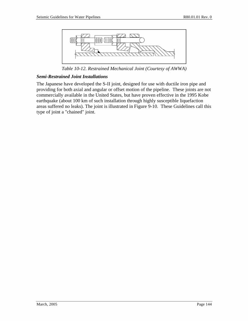
Seismic Guidelines for Water Pipelines R80.01.01 Rev. 0
March, 2005 Page 144
Table 10-12. Restrained Mechanical Joint (Courtesy of AWWA)
Semi-Restrained Joint Installations
The Japanese have developed the S-II joint, designed for use with ductile iron pipe and providing for both axial and angular or offset motion of the pipeline. These joints are not commercially available in the United States, but have proven effective in the 1995 Kobe earthquake (about 100 km of such installation through highly susceptible liquefaction areas suffered no leaks). The joint is illustrated in Figure 9-10. These Guidelines call this type of joint a "chained" joint.