
Sediment Basin Design Basics w/ Surface Dewatering Devices · Sediment Basin Design Basics w/...
16
Oklahoma DOT E&SC Workshop June 13, 2016 Module 4: Sed Basin Design Basics 1 Sediment Basin Design Basics w/ Surface Dewatering Devices Sediment Removal • Gravity; Stokes Law – Particle diameter. – Liquid viscosity = f(temperature). – Particle density = 2.65 g/cc (165 #/ft 3 ) • Assumptions: – Water velocity = Zero (0); quiescent – Water temperature = 68ºF – Laminar flow; Reynolds No. < 0.5 ) 1 ( 18 1 2 SG g d V s 0.00000001 0.00000100 0.00010000 0.01000000 1.00000000 100.00000000 0.1 1 10 100 1000 10000 Particle Diameter, D (microns) Settling Velocity, Vs (ft/s) CLAY SILT SAND GRAVEL 435 ft 2 /cfs Settling Velocity
Transcript of Sediment Basin Design Basics w/ Surface Dewatering Devices · Sediment Basin Design Basics w/...

Oklahoma DOT E&SC Workshop June 13, 2016
Module 4: Sed Basin Design Basics 1
Sediment Basin Design Basics w/ Surface Dewatering Devices
Sediment Removal• Gravity; Stokes Law
– Particle diameter.– Liquid viscosity = f(temperature).– Particle density = 2.65 g/cc (165 #/ft3)
• Assumptions:– Water velocity = Zero (0); quiescent– Water temperature = 68ºF– Laminar flow; Reynolds No. < 0.5
)1(
18
1 2
SGgd
Vs
0.00000001
0.00000100
0.00010000
0.01000000
1.00000000
100.00000000
0.1 1 10 100 1000 10000
Particle Diameter, D (microns)
Se
ttli
ng
Ve
loc
ity
, V
s (
ft/s
)
CLAY
SILT
SAND
GRAVEL
435 ft2/cfs
Settling Velocity
Oklahoma DOT E&SC Workshop June 13, 2016
Module 4: Sed Basin Design Basics 2
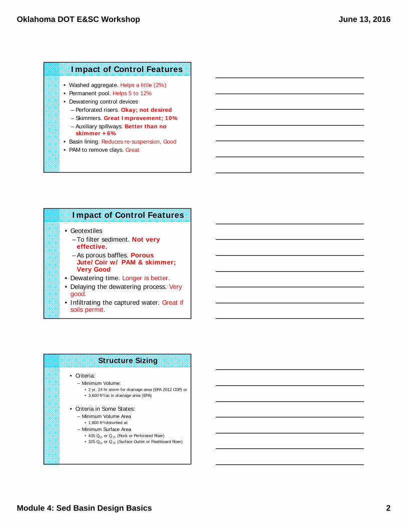
Impact of Control Features
• Washed aggregate. Helps a little (2%)• Permanent pool. Helps 5 to 12%• Dewatering control devices
– Perforated risers. Okay; not desired– Skimmers. Great Improvement; 10%– Auxiliary spillways. Better than no
skimmer +6%• Basin lining. Reduces re-suspension, Good• PAM to remove clays. Great
Impact of Control Features
• Geotextiles– To filter sediment. Not very
effective.– As porous baffles. Porous
Jute/Coir w/ PAM & skimmer; Very Good
• Dewatering time. Longer is better.• Delaying the dewatering process. Very
good.• Infiltrating the captured water. Great if
soils permit.
Structure Sizing
• Criteria:– Minimum Volume:
• 2 yr, 24 hr storm for drainage area (EPA 2012 CGP) or• 3,600 ft3/ac in drainage area (EPA)
• Criteria in Some States:– Minimum Volume Area
• 1,800 ft3/disturbed ac
– Minimum Surface Area• 435 Q10 or Q 25 (Rock or Perforated Riser)• 325 Q10 or Q 25 (Surface Outlet or Flashboard Riser)

Oklahoma DOT E&SC Workshop June 13, 2016
Module 4: Sed Basin Design Basics 3
Sizing Example
• Determine the minimum volume and surface area for a Temporary Sediment Trap serving a 1.2-acre road construction site with a 2 acre watershed with a Q10 = 7 cfs.
• Solution:– Minimum Volume = 3600(2) = 7200 ft3
– Minimum Surface Area = 435(7) = 3045 ft2
Controlling Discharge
• Rock outlet• Perforated Riser• Skimmer• Flashboard riser
Rock Outlet
• When sediment laden water gets to the rock (porous) outlet, sediment remains in suspension.
Oklahoma DOT E&SC Workshop June 13, 2016
Module 4: Sed Basin Design Basics 4
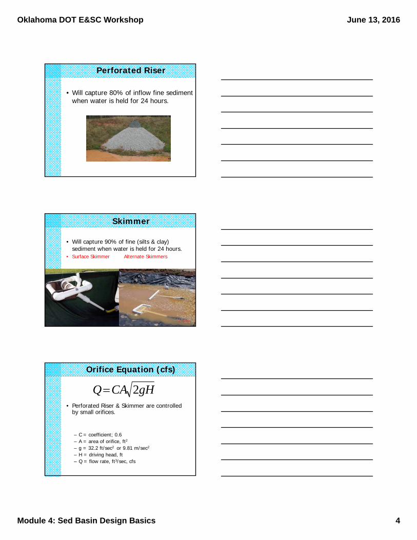
Perforated Riser
• Will capture 80% of inflow fine sediment when water is held for 24 hours.
Skimmer
• Will capture 90% of fine (silts & clay) sediment when water is held for 24 hours.
• Surface Skimmer Alternate Skimmers
Orifice Equation (cfs)
• Perforated Riser & Skimmer are controlled by small orifices.
– C = coefficient; 0.6– A = area of orifice, ft2
– g = 32.2 ft/sec2 or 9.81 m/sec2
– H = driving head, ft– Q = flow rate, ft3/sec, cfs
gHCAQ 2

Oklahoma DOT E&SC Workshop June 13, 2016
Module 4: Sed Basin Design Basics 5
Orifice Equation (gpm)• Alternate form (gpm):
– Where D = diameter, inches– H = head, ft– Last example: D = 0.75 in, H = 1.5 ft
HDQ 212
gpmHDQ 1.85.1)75.0(1212 22
Orifice Equation Example• A skimmer has a 2-in orifice and a head of
0.25 ft. What is the skimmer’s discharge rate?• Solution: D = 2 in; H = 0.25 ft
gpmHDQ 2425.0)2(1212 22
Orifice Equation (ft3/d)• Alternate form (ft3/d):
– Where D = diameter, inches– H = head, ft– Last example: D = 2 in, H = 0.25 ft
HDQ 22310
dftHDQ /462025.0)2(23102310 322

Oklahoma DOT E&SC Workshop June 13, 2016
Module 4: Sed Basin Design Basics 6
Surface Skimmer Sizing
• Determine the desired outflow rate, Q (ft3/d) based on:– Volume of the basin, V in ft3
– Desired dewatering time, td in days.
dt
VQ
• Example: Dewater 21,000 ft3 in 3 days.
days
ft
t
VQ
d 3
21000 3
Select skimmer based on desired flow rate from Table 4-1
0.50097,9788.00.41751,8406.00.33332,8325.00.33320,1094.00.2509,7743.00.2086,2342.50.1673,2832.00.1251,7281.5
Driving Head (ft)
Max. Outflow
Rate (ft3/d)
Skimmer Diameter (in)
Table 4-1
Skimmer Orifice Sizing
• Apply the orifice equation to size the orifice diameter & radius
– If we use a 3-inch skimmer (H = 0.250 ft), we can size the orifice as:
inchesH
QD 5.2
250.02310
7000
2310
inchesDr 3.12/5.22/

Oklahoma DOT E&SC Workshop June 13, 2016
Module 4: Sed Basin Design Basics 7
Flashboard Riser
• Works like a skimmer but with more labor.
Dewatering Via Infiltration
• Can be effective into sandy soils.
• Compute the dewatering time knowing:– The soil’s infiltration rate (permeability)– Depth of water in basin
)()/(_
)(_hours
I
D
hrinrateonInfiltrati
inchesdepthwaterTd
Infiltration Rate
– Equals the soil’s permeability• Given by NRCS in ranges; ex. 0.6 to 2.0 in/hr.
– Use permeability from slowest permeable soil horizon; usually B or C horizon.
– Use the lower value.– That’s the lowest value from slowest
layer.

Oklahoma DOT E&SC Workshop June 13, 2016
Module 4: Sed Basin Design Basics 8
Dewatering Time
• Example: 10,000 ft3 basin has a design depth of 1.5 feet. Soil has I = 0.6 in/hr.
ft
inx
hrin
ft
hrinI
inDTd 1
12
/6.0
5.1
)/(
)(
Emergency Spillway
Emergency Spillway
12.05
10.04
8.03
6.02
4.01
Minimum Emergency Spillway Width orBroad Crested Weir Length (ft)Drainage Area (acres)

Oklahoma DOT E&SC Workshop June 13, 2016
Module 4: Sed Basin Design Basics 9
Weir Equation
• Flow from an emergency spillway or a flashboard riser is controlled by the weir equation.
• Where:– L = width of the weir, ft– H = the driving head (1 ft max), ft– Q = flow rate, cfs
5.15.2 LHQ
Weir Equation Example
• How wide should an emergency spillway be to carry Q10 = 20 cfs with a maximum head of 0.5 ft.
Sediment Control BMPs• Coir Fiber Baffles • Rock Sediment Dams• Skimmer Basin• Tiered Skimmer Basin• Riser Basin• Infiltration Basin
Oklahoma DOT E&SC Workshop June 13, 2016
Module 4: Sed Basin Design Basics 10
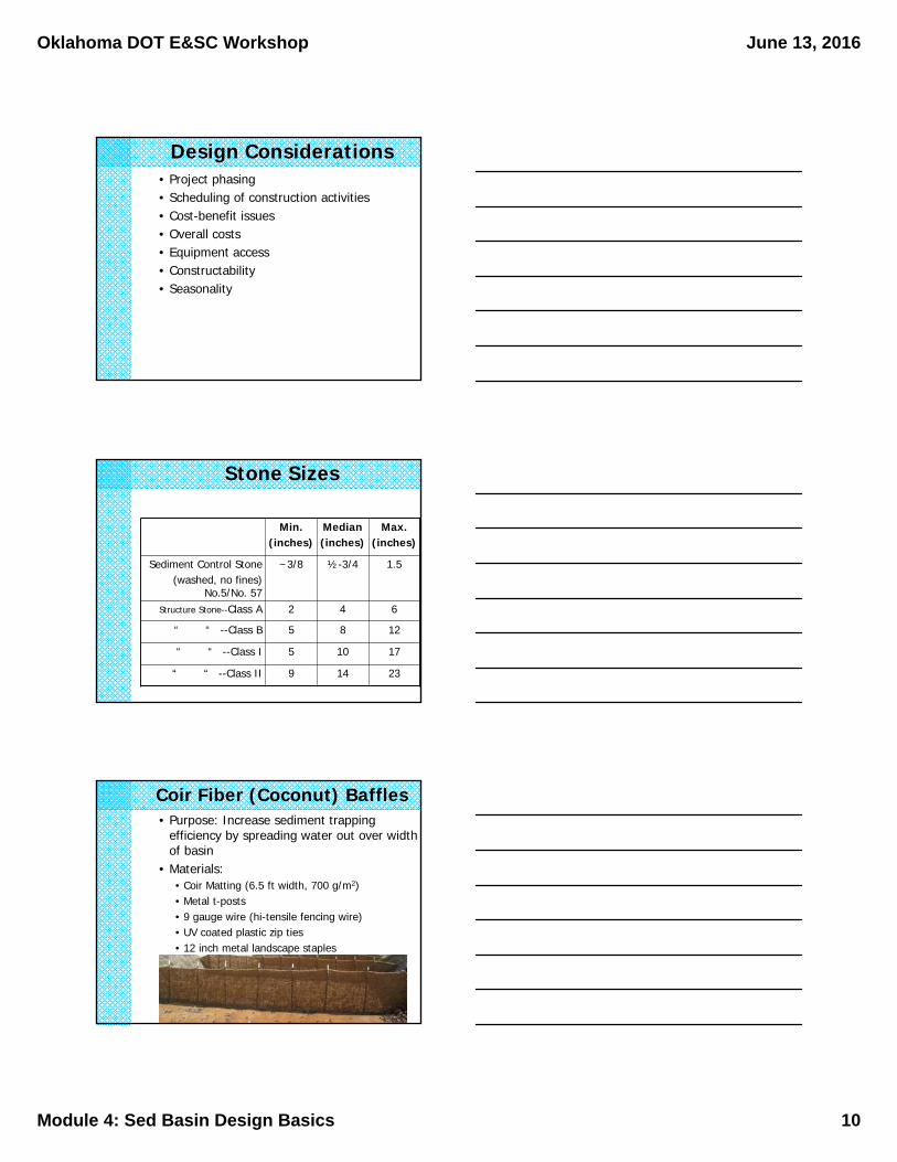
• Project phasing• Scheduling of construction activities• Cost-benefit issues• Overall costs • Equipment access• Constructability• Seasonality
Design Considerations
Stone Sizes
Min.(inches)
Median(inches)
Max.(inches)
Sediment Control Stone(washed, no fines)
No.5/No. 57
~3/8 ½-3/4 1.5
Structure Stone--Class A 2 4 6
“ “ --Class B 5 8 12
“ “ --Class I 5 10 17
“ “ --Class II 9 14 23
Coir Fiber (Coconut) Baffles• Purpose: Increase sediment trapping
efficiency by spreading water out over width of basin
• Materials: • Coir Matting (6.5 ft width, 700 g/m2)• Metal t-posts• 9 gauge wire (hi-tensile fencing wire)• UV coated plastic zip ties• 12 inch metal landscape staples

Oklahoma DOT E&SC Workshop June 13, 2016
Module 4: Sed Basin Design Basics 11
Coir Fiber (Coconut) Baffles
• Large rock dam with weir outlet
• Location: site perimeter• Drainage area < 10ac• Surf. Area: 435Q10 or Q25• Volume: 3600ft3/ac• Class I structure stone• Sediment control stone
on inlet face• Earthen walls built above
grade• L:W ratio range 2:1-5:1
Temporary Rock Sediment Dam-Type A
Temporary Rock Sediment Dam-Type A

Oklahoma DOT E&SC Workshop June 13, 2016
Module 4: Sed Basin Design Basics 12
Temp. Rock Sediment Dam – Type B
• Small rock dam with weir outlet
• Location: site perimeter• Drainage area < 5ac
• Surf. Area: 435Q10 or Q25
• Volume: 3600ft3/ac
• Class B structure stone
• Sediment control stone face
• 3 coir baffles• Earthen walls built
above grade• L:W ratio range
2:1-5:1
Temp. Rock Sediment Dam – Type B
Skimmer Basin w/ Baffles• Rectangular basin• 3 coir baffles • Location: site perimeter• Drainage area < 10ac• Surf. Area: 325Q10 or Q25• Volume: 1800 ft3/ac• Surface outlet devices
– Surface Skimmer– Weir
• Earthen walls (above grade)• L:W ratio range 3:1-5:1• Drawdown in 2-3 days
(top 2 ft only)• Max depth to weir, 3 ft

Oklahoma DOT E&SC Workshop June 13, 2016
Module 4: Sed Basin Design Basics 13
Skimmer Basin w/ Baffles
Skimmer Basin Detail
3’
Not to Scale
1/4L1/2L
3/4LL = 3W min
1’ min
Emer Spwy
Filter Fabric
Coir Fiber Mat
9’ min
6’ mi
Coir Porous Baffles
Steel Posts
12 inch Slope
Drain Pipe3:1 max
1.5:1 max
1’ min
Skimmer
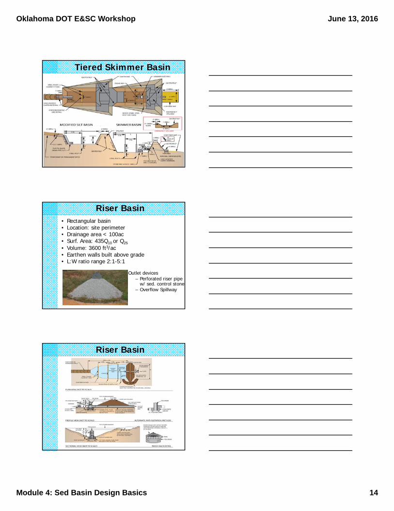
Tiered Skimmer Basin• Rectangular basin• 2 basins at diff. elev.• 3 coir baffles • Location: site perimeter• Drainage area < 10ac• Surf. Area: 325Q10 or Q25• Volume: 1800 ft3/ac• Surface outlet devices
– Skimmer– Weir
• Earthen walls built above grade
• L:W ratio range 3:1-5:1
Oklahoma DOT E&SC Workshop June 13, 2016
Module 4: Sed Basin Design Basics 14
Tiered Skimmer Basin
Riser Basin• Rectangular basin• Location: site perimeter• Drainage area < 100ac• Surf. Area: 435Q10 or Q25• Volume: 3600 ft3/ac• Earthen walls built above grade• L:W ratio range 2:1-5:1
Outlet devices– Perforated riser pipe
w/ sed. control stone– Overflow Spillway
Riser Basin
Oklahoma DOT E&SC Workshop June 13, 2016
Module 4: Sed Basin Design Basics 15
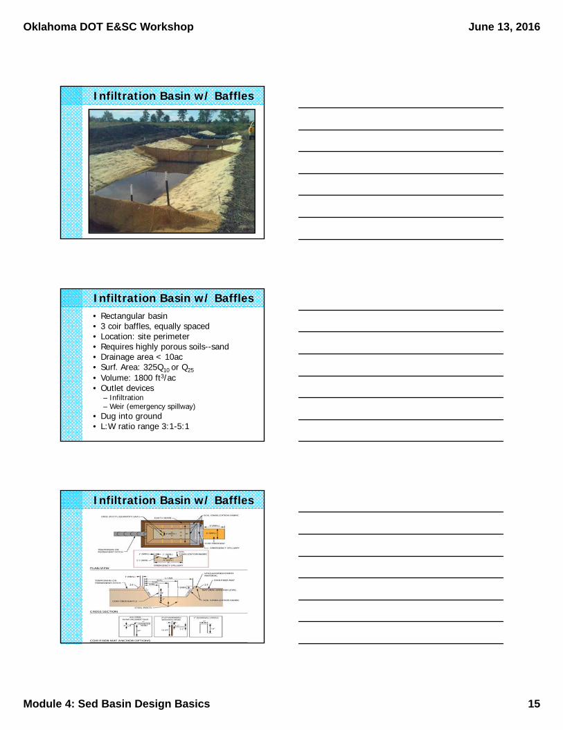
Infiltration Basin w/ Baffles
Infiltration Basin w/ Baffles• Rectangular basin• 3 coir baffles, equally spaced • Location: site perimeter• Requires highly porous soils--sand• Drainage area < 10ac• Surf. Area: 325Q10 or Q25• Volume: 1800 ft3/ac• Outlet devices
– Infiltration– Weir (emergency spillway)
• Dug into ground• L:W ratio range 3:1-5:1
Infiltration Basin w/ Baffles
Oklahoma DOT E&SC Workshop June 13, 2016
Module 4: Sed Basin Design Basics 16
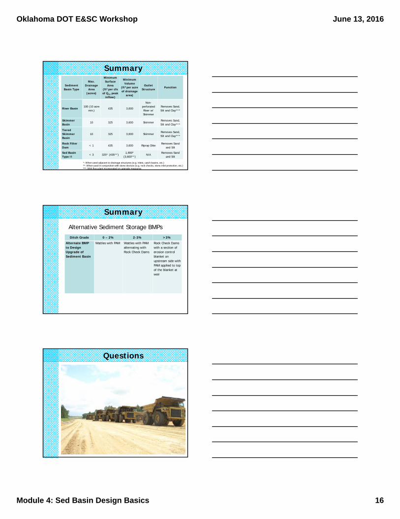
Summary
Sediment Basin Type
Max. Drainage
Area (acres)
Minimum Surface
Area (ft2 per cfsof Q10 peak
inflow)
Minimum Volume
(ft3 per acre of drainage
area)
Outlet Structure
Function
Riser Basin100 (10 acre
min.)435 3,600
Non-perforated Riser w/ Skimmer
Removes Sand, Silt and Clay***
Skimmer Basin
10 325 3,600 SkimmerRemoves Sand, Silt and Clay***
Tiered Skimmer Basin
10 325 3,600 SkimmerRemoves Sand, Silt and Clay***
Rock FilterDam
< 1 435 3,600 Riprap DikeRemoves Sand
and Silt
Sed Basin Type II
< 3 325* (435**)1,800*
(3,600**)N/A
Removes Sand and Silt
*- When used adjacent to drainage structures (e.g. inlets, catch basins, etc.)**- When used in conjunction with stone devices (e.g. rock checks, stone inlet protection, etc.)***- With flocculant incorporated on upgrade measures
Summary
Ditch Grade 0 – 2% 2-3% >3%
Alternate BMP to Design Upgrade of Sediment Basin
Wattles with PAM Wattles with PAM alternating with Rock Check Dams
Rock Check Dams with a section of erosion control blanket on upstream side with PAM applied to top of the blanket at weir
Alternative Sediment Storage BMPs
Questions