
SECTION MANUAL TRANSAXLE... · a: 68 mm (2.68 in) dia. b: 60 mm (2.36 in) dia. KV38102510 (—)...
70
MT-1 MANUAL TRANSAXLE C TRANSMISSION/TRANSAXLE CONTENTS D E F G H I J K L M SECTION A B MT PRECAUTIONS ......................................................... 3 Caution .................................................................... 3 PREPARATION .......................................................... 4 Special Service Tools .............................................. 4 Commercial Service Tools ....................................... 6 NOISE, VIBRATION, AND HARSHNESS (NVH) TROUBLESHOOTING ............................................... 7 NVH Troubleshooting Chart .................................... 7 DESCRIPTION ........................................................... 8 Cross-sectional View ............................................... 8 DOUBLE-CONE SYNCHRONIZER ..................... 9 TRIPLE-CONE SYNCHRONIZER ....................... 9 REVERSE GEAR ................................................. 9 M/T OIL .................................................................... 10 Replacement ......................................................... 10 DRAINING .......................................................... 10 FILLING .............................................................. 10 Checking ............................................................... 10 OIL LEAKAGE AND OIL LEVEL ........................ 10 SIDE OIL SEAL ........................................................ 11 Removal and Installation ........................................ 11 REMOVAL ........................................................... 11 INSTALLATION ................................................... 11 POSITION SWITCH ................................................. 12 Checking ............................................................... 12 BACK-UP LAMP SWITCH ................................. 12 PARK/NEUTRAL POSITION SWITCH .............. 12 CONTROL LINKAGE .............................................. 13 Removal and Installation of Control Device and Cable ..................................................................... 13 AIR BREATHER HOSE ........................................... 15 Removal and Installation ....................................... 15 TRANSAXLE ASSEMBLY ....................................... 16 Removal and Installation ....................................... 16 REMOVAL .......................................................... 16 INSTALLATION .................................................. 17 Component Parts .................................................. 19 CASE AND HOUSING COMPONENTS ............ 19 GEAR COMPONENTS ...................................... 20 SHIFT CONTROL COMPONENTS ................... 22 FINAL DRIVE COMPONENTS (RS6F51A) ........ 23 FINAL DRIVE COMPONENTS (RS6F51H) ....... 24 Disassembly and Assembly ................................... 24 DISASSEMBLY .................................................. 24 ASSEMBLY ........................................................ 28 Adjustment ............................................................. 35 INPUTSHAFT END PLAY .................................. 35 DIFFERENTIAL SIDE BEARING PRELOAD ..... 36 MAINSHAFT END PLAY .................................... 37 REVERSE IDLER GEAR END PLAY ................. 38 INPUT SHAFT AND GEARS ................................... 40 Disassembly and Assembly ................................... 40 DISASSEMBLY .................................................. 40 INSPECTION AFTER DISASSEMBLY ............... 41 ASSEMBLY ........................................................ 42 MAINSHAFT AND GEARS ...................................... 47 Disassembly and Assembly ................................... 47 DISASSEMBLY .................................................. 47 INSPECTION AFTER DISASSEMBLY ............... 48 ASSEMBLY ........................................................ 51 REVERSE IDLER SHAFT AND GEARS ................. 56 Disassembly and Assembly ................................... 56 DISASSEMBLY .................................................. 56 INSPECTION AFTER DISASSEMBLY ............... 56 ASSEMBLY ........................................................ 57 FINAL DRIVE (RS6F51A) ........................................ 58 Disassembly and Assembly ................................... 58 PRE-INSPECTION ............................................. 58 DISASSEMBLY .................................................. 58 INSPECTION AFTER DISASSEMBLY ............... 59 ASSEMBLY ........................................................ 59 FINAL DRIVE (RS6F51H) ........................................ 62 Disassembly and Assembly ................................... 62 DISASSEMBLY .................................................. 62 INSPECTION AFTER DISASSEMBLY ............... 62 ASSEMBLY ........................................................ 62 SHIFT CONTROL .................................................... 64 Inspection .............................................................. 64 SHIFT FORK ...................................................... 64 SERVICE DATA AND SPECIFICATIONS (SDS) ..... 65
Transcript of SECTION MANUAL TRANSAXLE... · a: 68 mm (2.68 in) dia. b: 60 mm (2.36 in) dia. KV38102510 (—)...

MT-1
MANUAL TRANSAXLE
C TRANSMISSION/TRANSAXLE
CONTENTS
D
E
F
G
H
I
J
K
L
M
SECTION
A
B
MT
PRECAUTIONS .......................................................... 3Caution ..................................................................... 3
PREPARATION ........................................................... 4Special Service Tools ............................................... 4Commercial Service Tools ........................................ 6
NOISE, VIBRATION, AND HARSHNESS (NVH) TROUBLESHOOTING ................................................ 7
NVH Troubleshooting Chart ..................................... 7DESCRIPTION ............................................................ 8
Cross-sectional View ................................................ 8DOUBLE-CONE SYNCHRONIZER ...................... 9TRIPLE-CONE SYNCHRONIZER ........................ 9REVERSE GEAR .................................................. 9
M/T OIL ..................................................................... 10Replacement .......................................................... 10
DRAINING ........................................................... 10FILLING ............................................................... 10
Checking ................................................................ 10OIL LEAKAGE AND OIL LEVEL ......................... 10
SIDE OIL SEAL .........................................................11Removal and Installation .........................................11
REMOVAL ............................................................11INSTALLATION ....................................................11
POSITION SWITCH .................................................. 12Checking ................................................................ 12
BACK-UP LAMP SWITCH .................................. 12PARK/NEUTRAL POSITION SWITCH ............... 12
CONTROL LINKAGE ............................................... 13Removal and Installation of Control Device and Cable ...................................................................... 13
AIR BREATHER HOSE ............................................ 15Removal and Installation ........................................ 15
TRANSAXLE ASSEMBLY ........................................ 16Removal and Installation ........................................ 16
REMOVAL ........................................................... 16INSTALLATION ................................................... 17
Component Parts ................................................... 19CASE AND HOUSING COMPONENTS ............. 19GEAR COMPONENTS ....................................... 20SHIFT CONTROL COMPONENTS .................... 22
FINAL DRIVE COMPONENTS (RS6F51A) ......... 23FINAL DRIVE COMPONENTS (RS6F51H) ........ 24
Disassembly and Assembly .................................... 24DISASSEMBLY ................................................... 24ASSEMBLY ......................................................... 28
Adjustment .............................................................. 35INPUTSHAFT END PLAY ................................... 35DIFFERENTIAL SIDE BEARING PRELOAD ...... 36MAINSHAFT END PLAY ..................................... 37REVERSE IDLER GEAR END PLAY .................. 38
INPUT SHAFT AND GEARS .................................... 40Disassembly and Assembly .................................... 40
DISASSEMBLY ................................................... 40INSPECTION AFTER DISASSEMBLY ................ 41ASSEMBLY ......................................................... 42
MAINSHAFT AND GEARS ....................................... 47Disassembly and Assembly .................................... 47
DISASSEMBLY ................................................... 47INSPECTION AFTER DISASSEMBLY ................ 48ASSEMBLY ......................................................... 51
REVERSE IDLER SHAFT AND GEARS .................. 56Disassembly and Assembly .................................... 56
DISASSEMBLY ................................................... 56INSPECTION AFTER DISASSEMBLY ................ 56ASSEMBLY ......................................................... 57
FINAL DRIVE (RS6F51A) ......................................... 58Disassembly and Assembly .................................... 58
PRE-INSPECTION .............................................. 58DISASSEMBLY ................................................... 58INSPECTION AFTER DISASSEMBLY ................ 59ASSEMBLY ......................................................... 59
FINAL DRIVE (RS6F51H) ......................................... 62Disassembly and Assembly .................................... 62
DISASSEMBLY ................................................... 62INSPECTION AFTER DISASSEMBLY ................ 62ASSEMBLY ......................................................... 62
SHIFT CONTROL ..................................................... 64Inspection ............................................................... 64
SHIFT FORK ....................................................... 64SERVICE DATA AND SPECIFICATIONS (SDS) ...... 65

MT-2
General Specifications ............................................ 65TRANSAXLE ....................................................... 65FINAL GEAR ....................................................... 66
Gear End Play ........................................................ 66Clearance Between Baulk Ring and Gear .............. 66
3RD, 4TH, 5TH, 6TH & REVERSE BAULK RING ... 661ST AND 2ND BAULK RING .............................. 67
Available Snap Rings .............................................. 676TH BUSHING .................................................... 67
Available C-rings ..................................................... 67MAINSHAFT C-RING .......................................... 67
Available Thrust Washers ....................................... 68INPUT SHAFT THRUST WASHER ..................... 68
Available Adjusting Shims .......................................68MAINSHAFT ADJUSTING SHIM .........................68INPUT SHAFT REAR BEARING ADJUSTING SHIM ....................................................................68MAINSHAFT REAR BEARING ADJUSTING SHIM ....................................................................69REVERASE IDLER GEAR ADJUSTING SHIM ...696TH MAIN GEAR ADJUSTING SHIM ..................69
Available Shims ......................................................69BEARING PRELOAD ...........................................69DIFFERENTIAL SIDE BEARING ADJUSTING SHIM(S) ...............................................................69

PRECAUTIONS
MT-3
D
E
F
G
H
I
J
K
L
M
A
B
MT
PRECAUTIONS PFP:00001
Caution ECS006RA
● Do not reuse transaxle oil, once it has been drained.● Check oil level, and drain and refill transaxle oil with the vehicle on level ground.● During removal or installation, keep inside of transaxle clean of dust and dirt.● Check for the correct installation orientation prior to removal or disassembly. If mating marks are required,
be certain they do not interfere with the function of the parts they are applied to.● In principle, tighten bolts or nuts gradually in several steps working diagonally and from inside to outside
as applicable. If a tightening sequence is specified, follow it as specified.● Be careful not to damage the sliding surfaces and mating surfaces of parts.

MT-4
PREPARATION
PREPARATION PFP:00002
Special Service Tools ECS006RB
The actual shapes of the Kent-Moore tools may differ from those of the special tools illustrated here.
Tool number(Kent-Moore No.)Tool name
Description
KV381054S0(J34286)Puller
Side bearing outer race removalMainshaft front bearing removal
ST35321000( — )Drift
Input shaft oil seal installationReverse main gear installation1st bushing installation1st-2nd synchronizer hub installation2nd bushing installation3rd main gear installationa: 49 mm (1.93 in) dia.b: 41 mm (1.61 in) dia.
ST30720000(J25405)Drift
Differential oil seal installationDifferential side bearing outer race installationMainshaft rear bearing installationDifferential side bearing installationa: 77 mm (3.03 in) dia.b: 55.5 mm (2.185 in) dia.
ST33200000(J26082)Drift
Mainshaft front bearing installation6th bushing installation4th main gear installation5th main gear installation6th main gear installationa: 60 mm (2.36 in) dia.b: 44.5 mm (1.752 in) dia.
ST33061000(J8107-2)Drift
Bore plug installationDifferential side bearing removala: 38 mm (1.50 in) dia.b: 28.5 mm (1.122 in) dia.
ST33052000( — )Drift
Welch plug installationInput shaft rear bearing removal5th bushing, thrust washer, 4th input gear, 4th gear bushing, 3rd-4th synchronizer hub and 3rd input gear removalInput shaft front bearing installation6th input gear and 6th bushing removalMainshaft rear bearing removal4th main gear and 5th main gear removal6th main gear removala: 22 mm (0.87 in) dia.b: 28 mm (1.10 in) dia.
ZZA0601D
ZZA1000D
ZZA0811D
ZZA1002D
ZZA1000D
ZZA1023D
PREPARATION
MT-5
D
E
F
G
H
I
J
K
L
M
A
B
MT
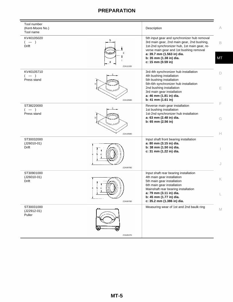
KV40105020( — )Drift
5th input gear and synchronizer hub removal3rd main gear, 2nd main gear, 2nd bushing, 1st-2nd synchronizer hub, 1st main gear, re-verse main gear and 1st bushing removala: 39.7 mm (1.563 in) dia.b: 35 mm (1.38 in) dia.c: 15 mm (0.59 in)
KV40105710( — )Press stand
3rd-4th synchronizer hub installation4th bushing installation5th bushing installation5th-6th synchronizer hub installation2nd bushing installation3rd main gear installationa: 46 mm (1.81 in) dia.b: 41 mm (1.61 in)
ST38220000( — )Press stand
Reverse main gear installation1st bushing installation1st-2nd synchronizer hub installationa: 63 mm (2.48 in) dia.b: 65 mm (2.56 in)
ST30032000(J26010-01)Drift
Input shaft front bearing installationa: 80 mm (3.15 in) dia.b: 38 mm (1.50 in) dia.c: 31 mm (1.22 in) dia.
ST30901000(J26010-01)Drift
Input shaft rear bearing installation4th main gear installation5th main gear installation6th main gear installationMainshaft rear bearing installationa: 79 mm (3.11 in) dia.b: 45 mm (1.77 in) dia.c: 35.2 mm (1.386 in) dia.
ST30031000(J22912-01)Puller
Measuring wear of 1st and 2nd baulk ring
Tool number(Kent-Moore No.)Tool name
Description
ZZA1133D
ZZA1058D
ZZA1058D
ZZA0978D
ZZA0978D
ZZA0537D

MT-6
PREPARATION
Commercial Service Tools ECS006RC
KV40101630(J35870)Drift
Reverse main gear installationa: 68 mm (2.68 in) dia.b: 60 mm (2.36 in) dia.
KV38102510( — )Drift
1st bushing installation1st-2nd synchronizer hub installationDifferential side bearing installationa: 71 mm (2.80 in) dia.b: 65 mm (2.56 in) dia.
Tool number(Kent-Moore No.)Tool name
Description
ZZA1003D
ZZA0838D
Tool name Description
Puller Each bearing gear and bushing removal
Power tool Loosening bolts and nuts
Puller Each bearing gear and bushing removal
Pin punch Each retaining pin removal and installationTip: 4.5 mm (0.177 in) dia.
ZZB0823D
PBIC0190E
NT077
ZZA0815D

NOISE, VIBRATION, AND HARSHNESS (NVH) TROUBLESHOOTING
MT-7
D
E
F
G
H
I
J
K
L
M
A
B
MT
NOISE, VIBRATION, AND HARSHNESS (NVH) TROUBLESHOOTING PFP:00003
NVH Troubleshooting Chart ECS006RD
Use the chart below to help you find the cause of the symptom. The numbers indicate the order of the inspec-tion. If necessary, repair or replace these parts.
Reference page
MT-
10
MT-
10
MT-
10
MT-
11
MT-
13
MT-
64
MT-
48, M
T-41
Suspected parts (possible cause)
(oil
leve
l is
low
)
(wro
ng o
il)
(oil
leve
l is
high
)
Gas
ket (
dam
aged
)
Oil
seal
(w
orn
or d
amag
ed)
O-R
ing
(wor
n or
dam
aged
)
Con
trol
dev
ice
and
cabl
e (w
orn)
Che
ck p
lug
retu
rn s
prin
g an
d ch
eck
ball
(wor
n or
dam
aged
)
Shi
ft fo
rk (
wor
n)
Gea
r (w
orn
or d
amag
ed)
Bea
ring
(wor
n or
dam
aged
)
Bau
lk r
ing
(wor
n or
dam
aged
)
Inse
rt s
prin
g, s
hifti
ng in
sert
(da
mag
ed)
Symptom
Noise 1 2 3 3
Oil leakage 3 1 2 2 2
Hard to shift or will not shift 1 1 2 3 3
Jumps out of gear 1 2 3 3

MT-8
DESCRIPTION
DESCRIPTION PFP:00000
Cross-sectional View ECS006RE
WCIA0201E
DESCRIPTION
MT-9
D
E
F
G
H
I
J
K
L
M
A
B
MT
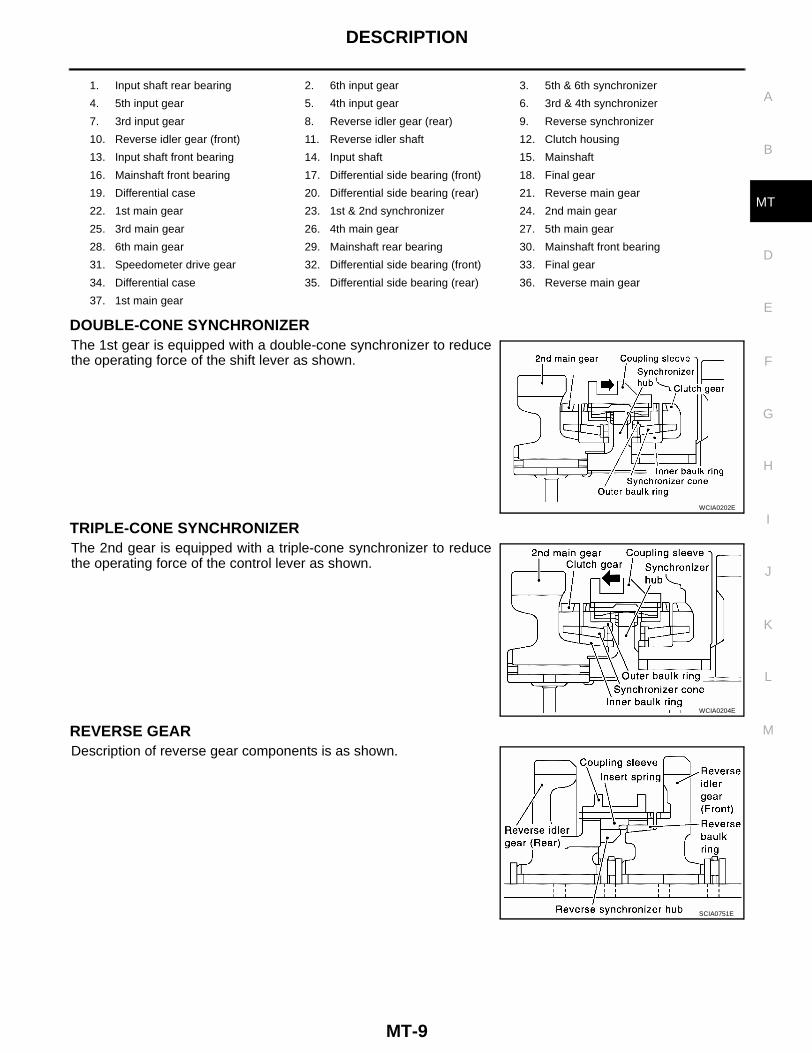
DOUBLE-CONE SYNCHRONIZERThe 1st gear is equipped with a double-cone synchronizer to reducethe operating force of the shift lever as shown.
TRIPLE-CONE SYNCHRONIZERThe 2nd gear is equipped with a triple-cone synchronizer to reducethe operating force of the control lever as shown.
REVERSE GEARDescription of reverse gear components is as shown.
1. Input shaft rear bearing 2. 6th input gear 3. 5th & 6th synchronizer
4. 5th input gear 5. 4th input gear 6. 3rd & 4th synchronizer
7. 3rd input gear 8. Reverse idler gear (rear) 9. Reverse synchronizer
10. Reverse idler gear (front) 11. Reverse idler shaft 12. Clutch housing
13. Input shaft front bearing 14. Input shaft 15. Mainshaft
16. Mainshaft front bearing 17. Differential side bearing (front) 18. Final gear
19. Differential case 20. Differential side bearing (rear) 21. Reverse main gear
22. 1st main gear 23. 1st & 2nd synchronizer 24. 2nd main gear
25. 3rd main gear 26. 4th main gear 27. 5th main gear
28. 6th main gear 29. Mainshaft rear bearing 30. Mainshaft front bearing
31. Speedometer drive gear 32. Differential side bearing (front) 33. Final gear
34. Differential case 35. Differential side bearing (rear) 36. Reverse main gear
37. 1st main gear
WCIA0202E
WCIA0204E
SCIA0751E
MT-10
M/T OIL
M/T OIL PFP:KLD20
Replacement ECS006RF
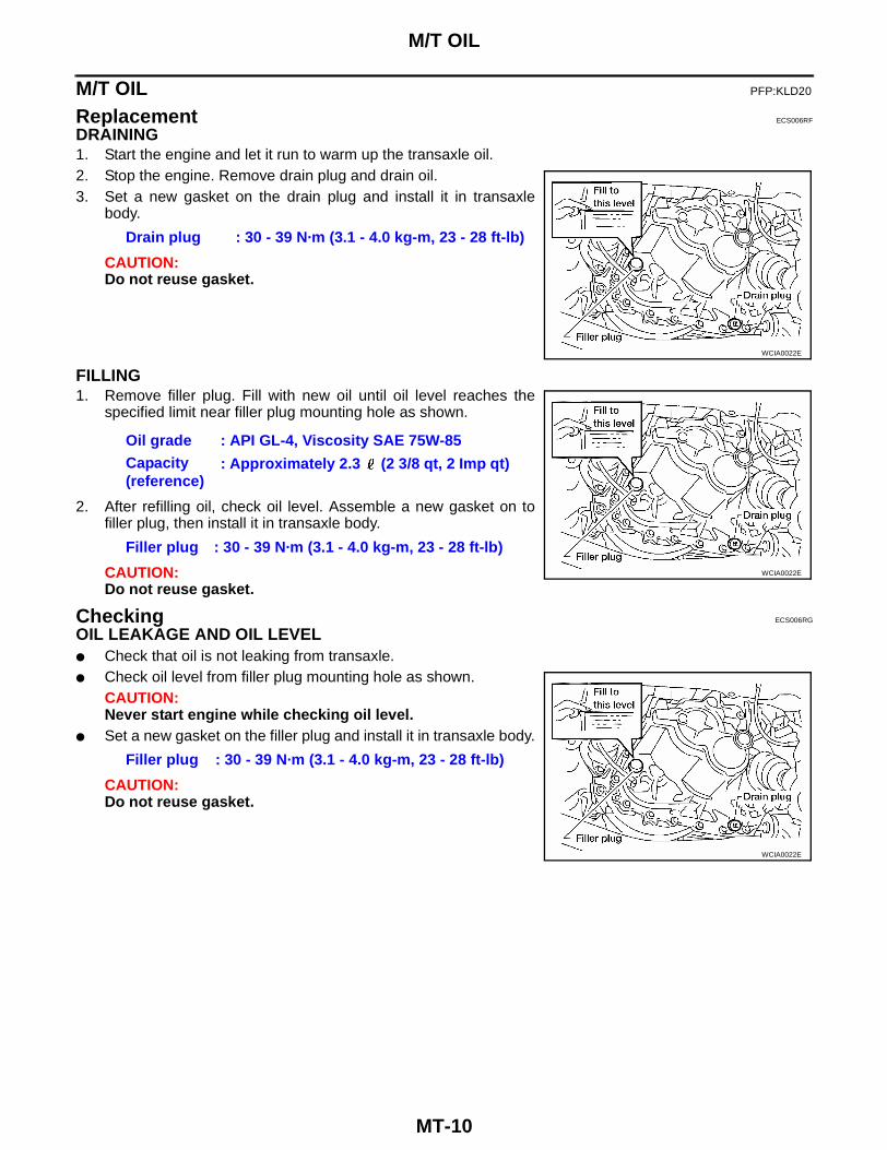
DRAINING1. Start the engine and let it run to warm up the transaxle oil.2. Stop the engine. Remove drain plug and drain oil.3. Set a new gasket on the drain plug and install it in transaxle
body.
CAUTION:Do not reuse gasket.
FILLING1. Remove filler plug. Fill with new oil until oil level reaches the
specified limit near filler plug mounting hole as shown.
2. After refilling oil, check oil level. Assemble a new gasket on tofiller plug, then install it in transaxle body.
CAUTION:Do not reuse gasket.
Checking ECS006RG
OIL LEAKAGE AND OIL LEVEL● Check that oil is not leaking from transaxle.● Check oil level from filler plug mounting hole as shown.
CAUTION:Never start engine while checking oil level.
● Set a new gasket on the filler plug and install it in transaxle body.
CAUTION:Do not reuse gasket.
Drain plug : 30 - 39 N·m (3.1 - 4.0 kg-m, 23 - 28 ft-lb)
WCIA0022E
Oil grade : API GL-4, Viscosity SAE 75W-85Capacity (reference)
: Approximately 2.3 (2 3/8 qt, 2 Imp qt)
Filler plug : 30 - 39 N·m (3.1 - 4.0 kg-m, 23 - 28 ft-lb)
WCIA0022E
Filler plug : 30 - 39 N·m (3.1 - 4.0 kg-m, 23 - 28 ft-lb)
WCIA0022E
SIDE OIL SEAL
MT-11
D
E
F
G
H
I
J
K
L
M
A
B
MT
SIDE OIL SEAL PFP:32113
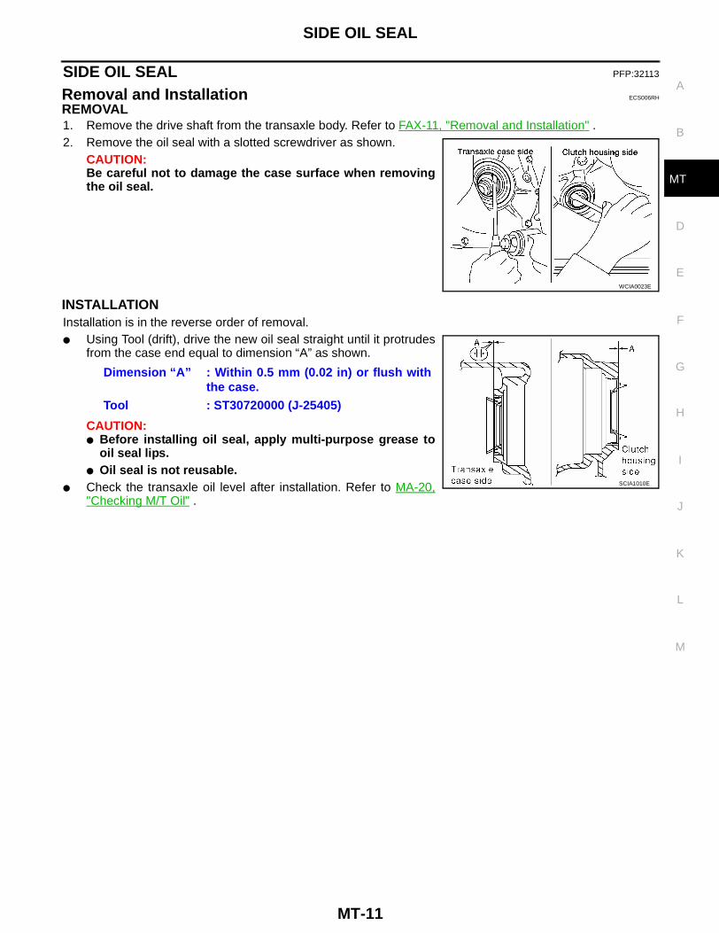
Removal and Installation ECS006RH
REMOVAL1. Remove the drive shaft from the transaxle body. Refer to FAX-11, "Removal and Installation" .2. Remove the oil seal with a slotted screwdriver as shown.
CAUTION:Be careful not to damage the case surface when removingthe oil seal.
INSTALLATIONInstallation is in the reverse order of removal.● Using Tool (drift), drive the new oil seal straight until it protrudes
from the case end equal to dimension “A” as shown.
CAUTION:● Before installing oil seal, apply multi-purpose grease to
oil seal lips.● Oil seal is not reusable.
● Check the transaxle oil level after installation. Refer to MA-20,"Checking M/T Oil" .
WCIA0023E
Dimension “A” : Within 0.5 mm (0.02 in) or flush withthe case.
Tool : ST30720000 (J-25405)
SCIA1010E
MT-12
POSITION SWITCH
POSITION SWITCH PFP:32005
Checking ECS006RI
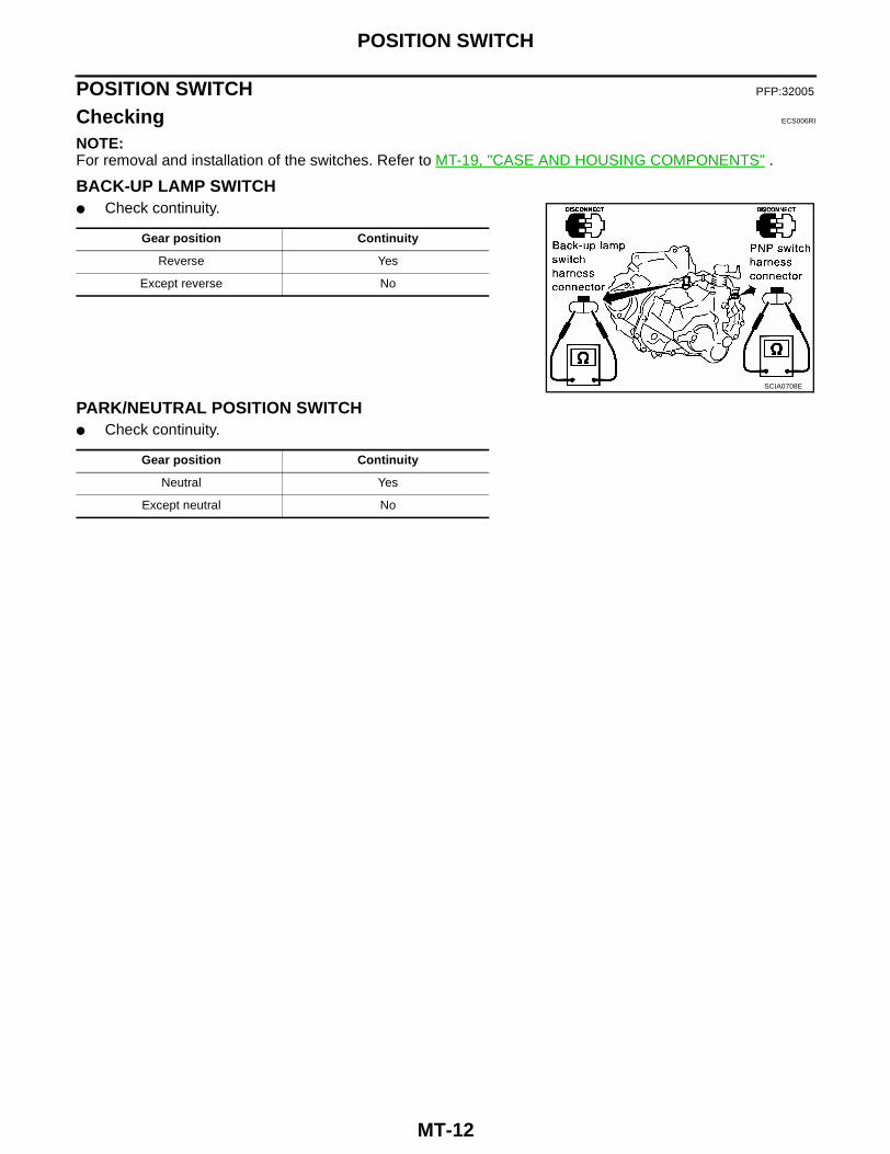
NOTE:For removal and installation of the switches. Refer to MT-19, "CASE AND HOUSING COMPONENTS" .
BACK-UP LAMP SWITCH● Check continuity.
PARK/NEUTRAL POSITION SWITCH● Check continuity.
Gear position Continuity
Reverse Yes
Except reverse No
SCIA0708E
Gear position Continuity
Neutral Yes
Except neutral No

CONTROL LINKAGE
MT-13
D
E
F
G
H
I
J
K
L
M
A
B
MT
CONTROL LINKAGE PFP:34103
Removal and Installation of Control Device and Cable ECS006RJ
1. Snap pin 2. Washer 3. Cable
4. Manual lever 5. Shift cable 6. Lock plate
7. Control device assembly 8. Lock plate 9. Select cable
10. Shift cable 11. Control lever knob 12. Control lever
WCIA0203E
MT-14
CONTROL LINKAGE
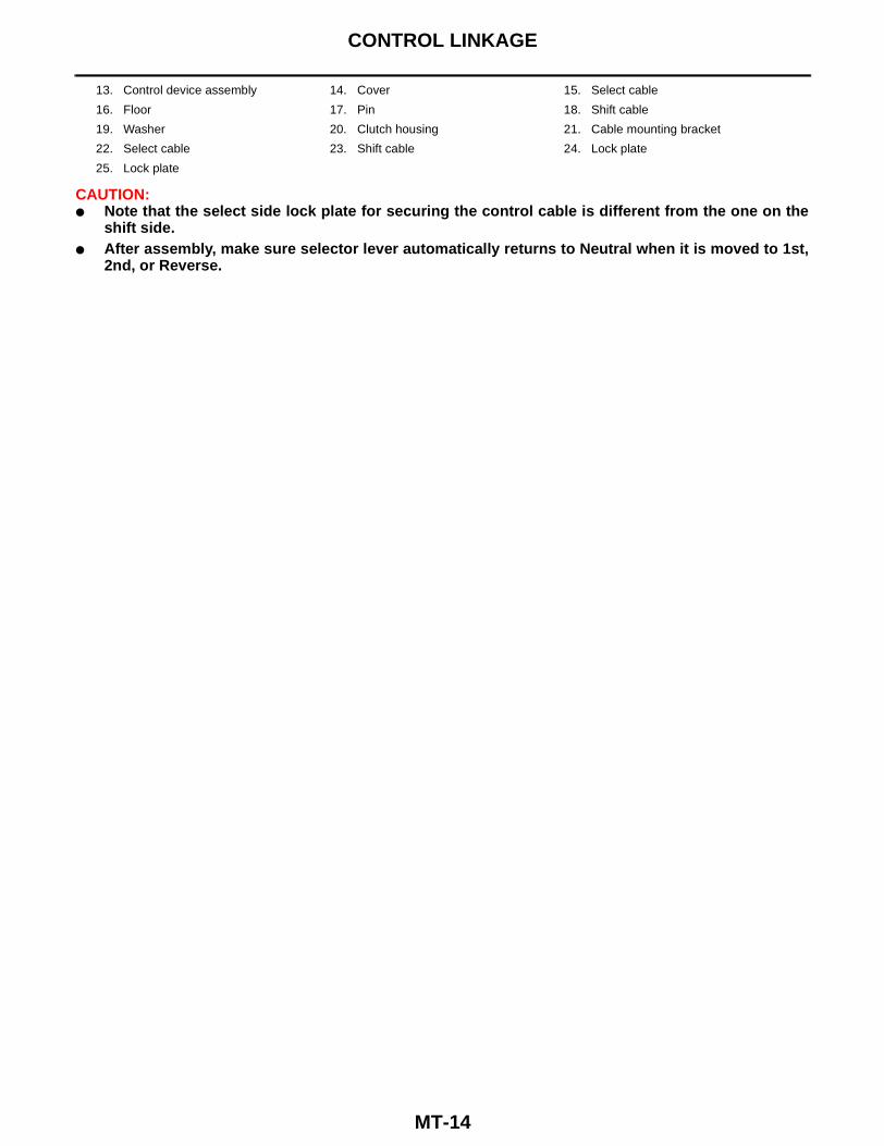
CAUTION:● Note that the select side lock plate for securing the control cable is different from the one on the
shift side.● After assembly, make sure selector lever automatically returns to Neutral when it is moved to 1st,
2nd, or Reverse.
13. Control device assembly 14. Cover 15. Select cable
16. Floor 17. Pin 18. Shift cable
19. Washer 20. Clutch housing 21. Cable mounting bracket
22. Select cable 23. Shift cable 24. Lock plate
25. Lock plate
AIR BREATHER HOSE
MT-15
D
E
F
G
H
I
J
K
L
M
A
B
MT
AIR BREATHER HOSE PFP:31098
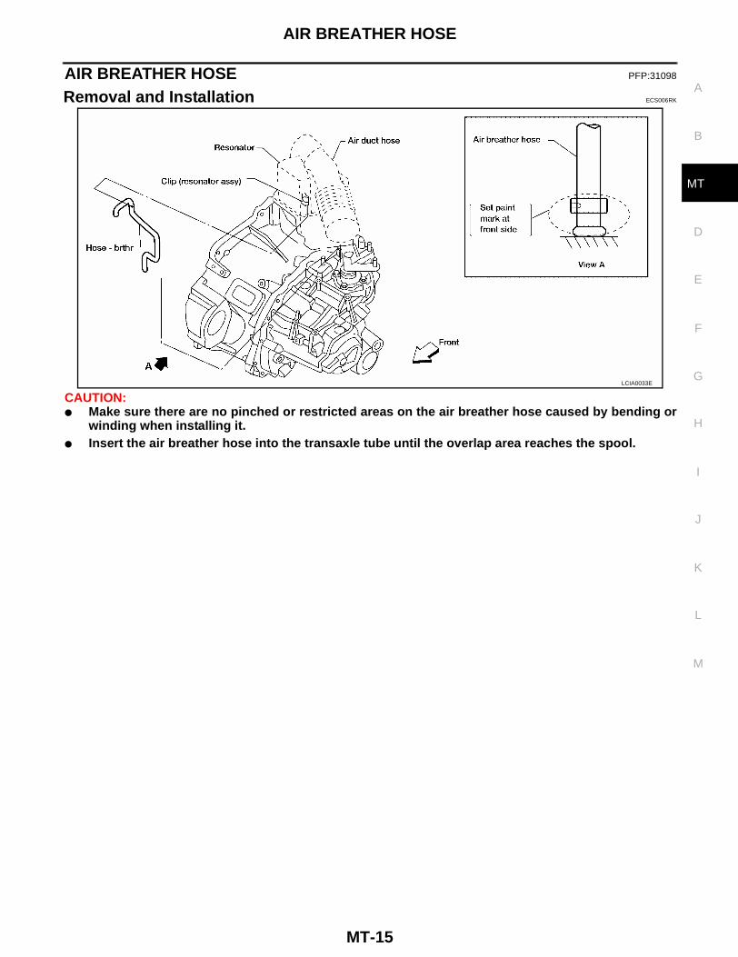
Removal and Installation ECS006RK
CAUTION:● Make sure there are no pinched or restricted areas on the air breather hose caused by bending or
winding when installing it.● Insert the air breather hose into the transaxle tube until the overlap area reaches the spool.
LCIA0033E
MT-16
TRANSAXLE ASSEMBLY
TRANSAXLE ASSEMBLY PFP:32010
Removal and Installation ECS006RL
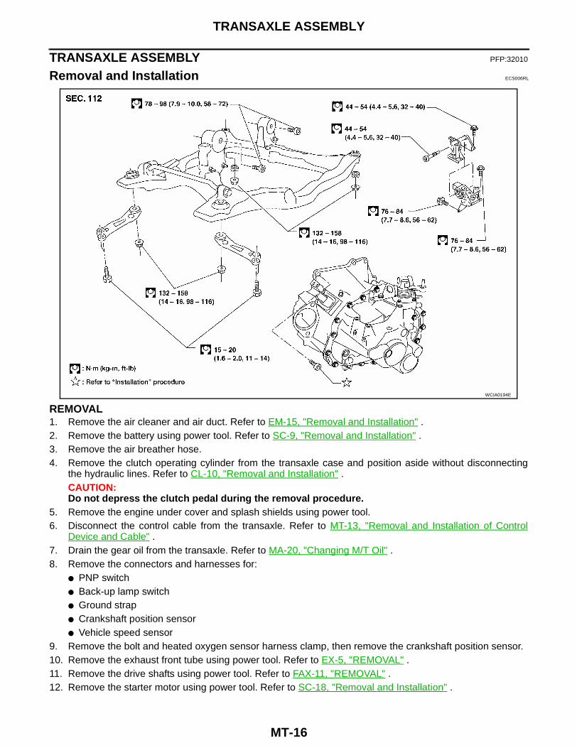
REMOVAL1. Remove the air cleaner and air duct. Refer to EM-15, "Removal and Installation" .2. Remove the battery using power tool. Refer to SC-9, "Removal and Installation" .3. Remove the air breather hose.4. Remove the clutch operating cylinder from the transaxle case and position aside without disconnecting
the hydraulic lines. Refer to CL-10, "Removal and Installation" .CAUTION:Do not depress the clutch pedal during the removal procedure.
5. Remove the engine under cover and splash shields using power tool.6. Disconnect the control cable from the transaxle. Refer to MT-13, "Removal and Installation of Control
Device and Cable" .7. Drain the gear oil from the transaxle. Refer to MA-20, "Changing M/T Oil" .8. Remove the connectors and harnesses for:
● PNP switch● Back-up lamp switch● Ground strap● Crankshaft position sensor● Vehicle speed sensor
9. Remove the bolt and heated oxygen sensor harness clamp, then remove the crankshaft position sensor.10. Remove the exhaust front tube using power tool. Refer to EX-5, "REMOVAL" .11. Remove the drive shafts using power tool. Refer to FAX-11, "REMOVAL" .12. Remove the starter motor using power tool. Refer to SC-18, "Removal and Installation" .
WCIA0194E
TRANSAXLE ASSEMBLY
MT-17
D
E
F
G
H
I
J
K
L
M
A
B
MT
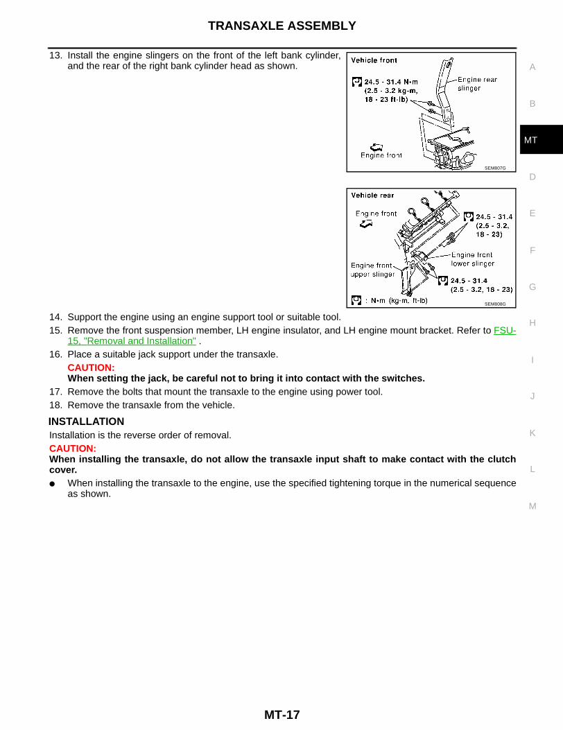
13. Install the engine slingers on the front of the left bank cylinder,and the rear of the right bank cylinder head as shown.
14. Support the engine using an engine support tool or suitable tool.15. Remove the front suspension member, LH engine insulator, and LH engine mount bracket. Refer to FSU-
15, "Removal and Installation" .16. Place a suitable jack support under the transaxle.
CAUTION:When setting the jack, be careful not to bring it into contact with the switches.
17. Remove the bolts that mount the transaxle to the engine using power tool.18. Remove the transaxle from the vehicle.
INSTALLATIONInstallation is the reverse order of removal.CAUTION:When installing the transaxle, do not allow the transaxle input shaft to make contact with the clutchcover.● When installing the transaxle to the engine, use the specified tightening torque in the numerical sequence
as shown.
SEM807G
SEM808G

MT-18
TRANSAXLE ASSEMBLY
● After installation, check the transaxle oil level, and check for any leaks and any loose mechanisms.
Bolt No. 1 2 3 4 5 6 7 8 9 10
“ ” mm (in) 52 (2.05) 113 (4.45) 40 (1.57)
Tightening torqueN·m (kg-m, ft-lb)
70 - 79 (7.1 - 8.1, 52 - 58) 36 - 47 (3.7 - 4.7, 27 - 34)
WCIA0193E
TRANSAXLE ASSEMBLY
MT-19
D
E
F
G
H
I
J
K
L
M
A
B
MT
Component Parts ECS006RM
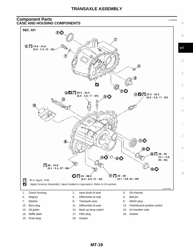
CASE AND HOUSING COMPONENTS
1. Clutch housing 2. Input shaft oil seal 3. Oil channel
4. Magnet 5. Differential oil seal 6. Ball pin
7. Washer 8. Transaxle case 9. Welch plug
10. Bore plug 11. Differential oil seal 12. Park/Neutral position switch
13. Oil gutter 14. Back-up lamp switch 15. Air breather tube
16. Baffle plate 17. Filler plug 18. Gasket
19. Drain plug 20. Gasket
SCIA1062E

MT-20
TRANSAXLE ASSEMBLY
GEAR COMPONENTS
1. Input shaft front bearing 2. Input shaft 3. Needle bearing
4. 3rd input gear 5. 3rd baulk ring 6. Spread spring
7. 3rd & 4th shifting insert 8. 3rd & 4th synchronizer hub 9. 4th baulk ring
10. 3rd & 4th coupling sleeve 11. Bushing 12. Needle bearing
13. 4th input gear 14. Thrust washer 15. Bushing
16. Needle bearing 17. 5th input gear 18. 5th baulk ring
19. 5th & 6th shifting insert 20. 5th & 6th synchronizer hub 21. 5th & 6th coupling sleeve
22. Baulk ring 23. 6th input gear 24. Needle bearing
25. Bushing 26. Snap ring 27. Input shaft rear bearing
28. Oil channel 29. Input shaft rear bearing adjusting shim
30. Retaining pin
31. Reverse idler shaft 32. Thrust bearing 33. Needle bearing
34. Reverse idler gear (Front) 35. Reverse baulk ring 36. Reverse coupling sleeve
37. Insert spring 38. Reverse idler gear (Rear) 39. Reverse idler gear adjusting shim
SCIA0956E
TRANSAXLE ASSEMBLY
MT-21
D
E
F
G
H
I
J
K
L
M
A
B
MT
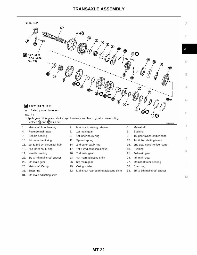
1. Mainshaft front bearing 2. Mainshaft bearing retainer 3. Mainshaft
4. Reverse main gear 5. 1st main gear 6. Bushing
7. Needle bearing 8. 1st inner baulk ring 9. 1st gear synchronizer cone
10. 1st outer baulk ring 11. Spread spring 12. 1st & 2nd shifting insert
13. 1st & 2nd synchronizer hub 14. 2nd outer baulk ring 15. 2nd gear synchronizer cone
16. 2nd inner baulk ring 17. 1st & 2nd coupling sleeve 18. Bushing
19. Needle bearing 20. 2nd main gear 21. 3rd main gear
22. 3rd & 4th mainshaft spacer 23. 4th main adjusting shim 24. 4th main gear
25. 5th main gear 26. 6th main gear 27. Mainshaft rear bearing
28. Mainshaft C-ring 29. C-ring holder 30. Snap ring
31. Snap ring 32. Mainshaft rear bearing adjusting shim 33. 5th & 6th mainshaft spacer
34. 6th main adjusting shim
SCIA0957E

MT-22
TRANSAXLE ASSEMBLY
SHIFT CONTROL COMPONENTS
1. Reverse shift fork 2. Shifter cap 3. Reverse fork rod
4. Reverse lever assembly 5. 5th & 6th bracket 6. 5th & 6th fork rod
7. 5th & 6th shift fork 8. Retaining pin 9. 3rd & 4th bracket
10. 3rd & 4th shift fork 11. 3rd & 4th fork rod 12. 1st & 2nd shift fork
13. 1st & 2nd bracket 14. 1st & 2nd fork rod 15. Shift check sleeve
16. Inter lock pin 17. Check ball 18. Shift check sleeve
19. Check spring 20. Check plug 21. Control assembly
22. O-ring 23. Shift check 24. Stopper bolt
25. Stopper ring 26. Reverse bracket fork rod 27. Reverse bracket
SCIA0958E

TRANSAXLE ASSEMBLY
MT-23
D
E
F
G
H
I
J
K
L
M
A
B
MT
FINAL DRIVE COMPONENTS (RS6F51A)
1. Differential side bearing adjusting shim
2. Differential side bearing outer race 3. Differential side bearing
4. Final gear 5. Differential case 6. Speedometer drive gear
7. Speedometer stopper 8. Differential side bearing 9. Differential side bearing outer race
10. Pinion mate thrust washer 11. Pinion mate gear 12. Side gear thrust washer
13. Side gear 14. Pinion mate shaft 15. Lock pin
WCIA0206E
MT-24
TRANSAXLE ASSEMBLY
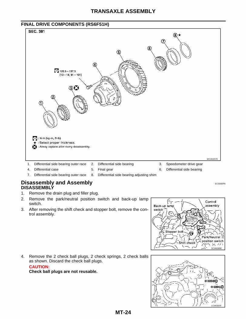
FINAL DRIVE COMPONENTS (RS6F51H)
Disassembly and Assembly ECS006RN
DISASSEMBLY1. Remove the drain plug and filler plug.2. Remove the park/neutral position switch and back-up lamp
switch.3. After removing the shift check and stopper bolt, remove the con-
trol assembly.
4. Remove the 2 check ball plugs, 2 check springs, 2 check ballsas shown. Discard the check ball plugs.CAUTION:Check ball plugs are not reusable.
1. Differential side bearing outer race 2. Differential side bearing 3. Speedometer drive gear
4. Differential case 5. Final gear 6. Differential side bearing
7. Differential side bearing outer race 8. Differential side bearing adjusting shim
WCIA0207E
SCIA0389E
LCIA0302E

TRANSAXLE ASSEMBLY
MT-25
D
E
F
G
H
I
J
K
L
M
A
B
MT
5. Remove the transaxle case fixing bolts as shown.
6. Remove the bore plug.CAUTION:Be careful not to damage transaxle case.
7. While spreading the snap ring of the mainshaft rear bearing located at bore plug hole, remove the tran-saxle case.
8. Remove the oil gutter and baffle plate.9. Remove the snap ring, mainshaft rear bearing adjusting shim, and input shaft rear bearing adjusting shim
from the transaxle case.
10. Remove the differential side bearing outer race (transaxle caseside) using Tool as shown, and then remove the adjusting shim.
11. Remove the welch plug with a suitable punch and hammer asshown.
12. Remove the differential oil seal with a suitable tool as shown.
13. Remove the magnet from the clutch housing.
SCIA0983E
SCIA1021E
SCIA0402E
SCIA0397E

MT-26
TRANSAXLE ASSEMBLY
14. Remove the reverse check ball plug, reverse check spring, reverse shift check sleeve, and check ball.Discard the check ball.CAUTION:● Do not reuse the check ball plug.● Do not drop the check ball.
15. With the shift lever in 5th position, remove the bracket bolts fromthe reverse lever assembly as shown. Lift the reverse leverassembly to remove.CAUTION:Retain the shifter cap for installation.
16. Pull out the reverse fork rod then remove the reverse shift fork.17. Remove the retaining pin of the reverse bracket.
18. Pull out the reverse lever and the reverse bracket fork rod.19. Remove the check ball (2 pieces) and the interlock pin.20. Shift the 3rd-4th fork rod to the 3rd position. Remove the retain-
ing pin of the 5th-6th shift fork using a pin punch.
21. Remove the stopper rings for the 5th-6th bracket.
22. Pull out the 5th-6th fork rod and remove the 5th-6th shift fork and the 5th-6th bracket.23. Remove the check balls (2 pieces) and interlock pin.
SCIA0960E
SCIA0961E
SCIA0962E
SCIA0963E
TRANSAXLE ASSEMBLY
MT-27
D
E
F
G
H
I
J
K
L
M
A
B
MT
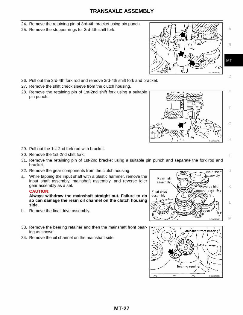
24. Remove the retaining pin of 3rd-4th bracket using pin punch.25. Remove the stopper rings for 3rd-4th shift fork.
26. Pull out the 3rd-4th fork rod and remove 3rd-4th shift fork and bracket.27. Remove the shift check sleeve from the clutch housing.28. Remove the retaining pin of 1st-2nd shift fork using a suitable
pin punch.
29. Pull out the 1st-2nd fork rod with bracket.30. Remove the 1st-2nd shift fork.31. Remove the retaining pin of 1st-2nd bracket using a suitable pin punch and separate the fork rod and
bracket.32. Remove the gear components from the clutch housing.a. While tapping the input shaft with a plastic hammer, remove the
input shaft assembly, mainshaft assembly, and reverse idlergear assembly as a set.CAUTION:Always withdraw the mainshaft straight out. Failure to doso can damage the resin oil channel on the clutch housingside.
b. Remove the final drive assembly.
33. Remove the bearing retainer and then the mainshaft front bear-ing as shown.
34. Remove the oil channel on the mainshaft side.
SCIA0393E
SCIA0394E
SCIA0964E
SCIA0400E

MT-28
TRANSAXLE ASSEMBLY
35. Remove the differential oil seal (clutch housing side) using Toolas shown.
36. Remove the differential side bearing outer race (clutch housingside) using Tool as shown.
37. Remove the input shaft oil seal using a suitable tool as shown.CAUTION:Do not damage the clutch housing sealing surface.
ASSEMBLY1. Install a new input shaft oil seal from the clutch housing end of
the side, to the depth of 1.8 - 2.8 mm (0.071 - 0.110 in) usingTool as shown.CAUTION:Oil seals are not reusable.
SMT117E
SMT116E
SCIA0398E
SCIA1022E

TRANSAXLE ASSEMBLY
MT-29
D
E
F
G
H
I
J
K
L
M
A
B
MT
2. Install a new differential oil seal using Tool (drift) as shown.CAUTION:Oil seals are not reusable.
3. Install the oil channel on the mainshaft side as shown.CAUTION:Position the oil channel with the orientation as shown, forinstallation.
4. Install the mainshaft front bearing using Tool (drift) as shown.CAUTION:Position the mainshaft front bearing with the orientation asshown, for installation
5. Install the mainshaft front bearing retainer.CAUTION:Install the bearing retainer with the punched surface facingup.
6. Install the differential side bearing outer race using Tool asshown.
SCIA1023E
SCIA0986E
SCIA1024E
Retainer bolt : 6.27 - 8.33 N·m (0.64 - 0.84 kg-m, 56 - 73 in-lb)
SCIA0400E
SCIA1063E
MT-30
TRANSAXLE ASSEMBLY
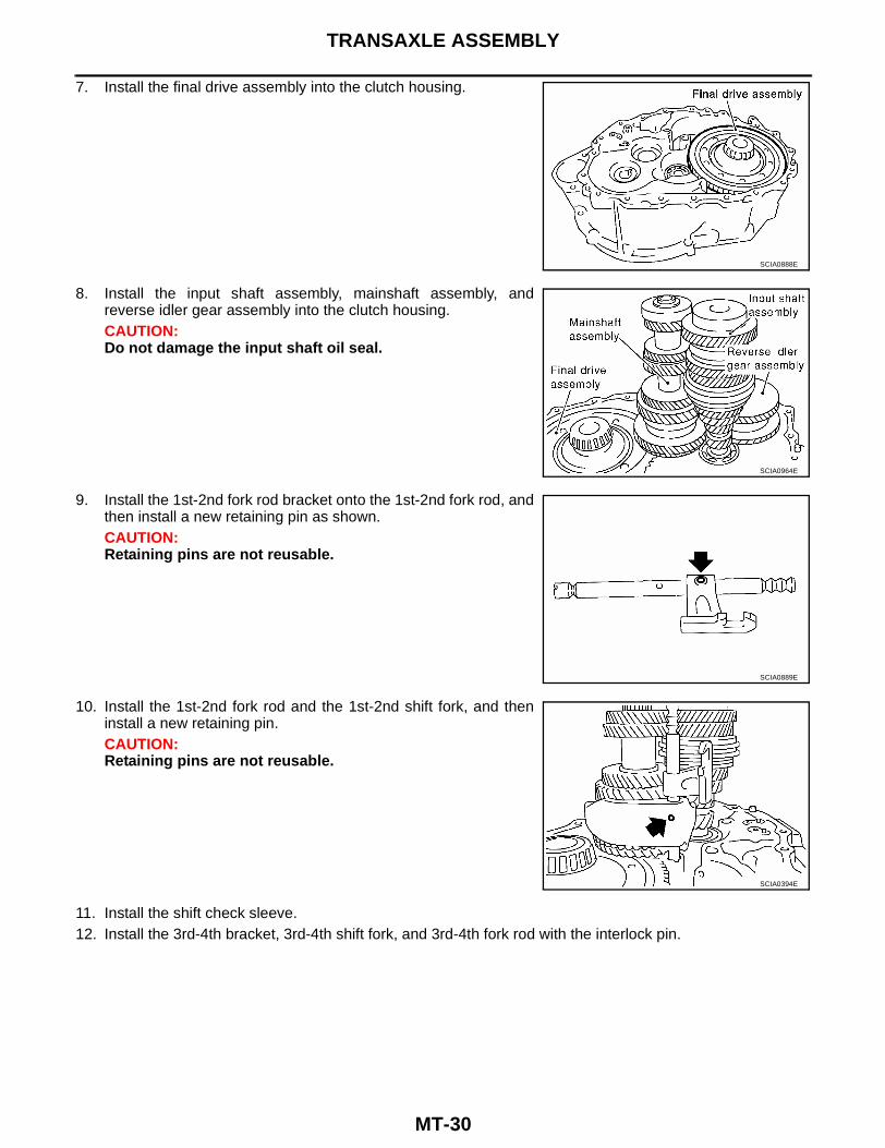
7. Install the final drive assembly into the clutch housing.
8. Install the input shaft assembly, mainshaft assembly, andreverse idler gear assembly into the clutch housing.CAUTION:Do not damage the input shaft oil seal.
9. Install the 1st-2nd fork rod bracket onto the 1st-2nd fork rod, andthen install a new retaining pin as shown.CAUTION:Retaining pins are not reusable.
10. Install the 1st-2nd fork rod and the 1st-2nd shift fork, and theninstall a new retaining pin.CAUTION:Retaining pins are not reusable.
11. Install the shift check sleeve.12. Install the 3rd-4th bracket, 3rd-4th shift fork, and 3rd-4th fork rod with the interlock pin.
SCIA0888E
SCIA0964E
SCIA0889E
SCIA0394E
TRANSAXLE ASSEMBLY
MT-31
D
E
F
G
H
I
J
K
L
M
A
B
MT
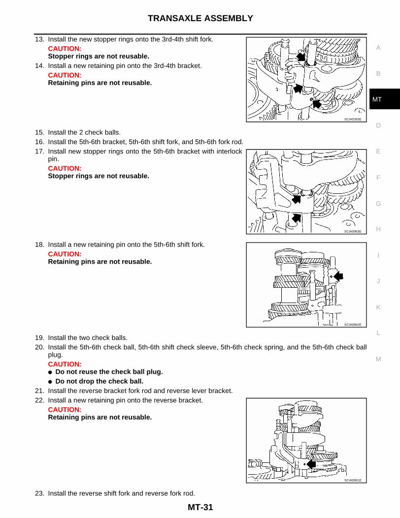
13. Install the new stopper rings onto the 3rd-4th shift fork.CAUTION:Stopper rings are not reusable.
14. Install a new retaining pin onto the 3rd-4th bracket.CAUTION:Retaining pins are not reusable.
15. Install the 2 check balls.16. Install the 5th-6th bracket, 5th-6th shift fork, and 5th-6th fork rod.17. Install new stopper rings onto the 5th-6th bracket with interlock
pin.CAUTION:Stopper rings are not reusable.
18. Install a new retaining pin onto the 5th-6th shift fork.CAUTION:Retaining pins are not reusable.
19. Install the two check balls.20. Install the 5th-6th check ball, 5th-6th shift check sleeve, 5th-6th check spring, and the 5th-6th check ball
plug.CAUTION:● Do not reuse the check ball plug.● Do not drop the check ball.
21. Install the reverse bracket fork rod and reverse lever bracket.22. Install a new retaining pin onto the reverse bracket.
CAUTION:Retaining pins are not reusable.
23. Install the reverse shift fork and reverse fork rod.
SCIA0393E
SCIA0963E
SCIA0962E
SCIA0961E

MT-32
TRANSAXLE ASSEMBLY
24. Install the reverse lever assembly using the following steps:a. Install the shifter cap onto the reverse lever assembly cam, and then install them onto the reverse shift
fork.CAUTION:Do not drop the shifter cap.
b. While lifting the reverse shift fork, align the cam with the reversebracket.
c. Tighten the bracket bolts to specification, and install the reverselever assembly.
25. Install the check ball, reverse shift check sleeve, reverse check spring, and the reverse check ball plug.CAUTION:● Do not reuse the check ball plug.● Do not drop the check ball.
26. Install the magnet onto the clutch housing.27. Install the selected input shaft adjusting shim onto the input shaft.
● For selection of adjusting shims, refer to MT-35, "INPUTSHAFT END PLAY" .28. Install the baffle plate and oil gutter.29. Install the transaxle case using the following steps:a. Install the selected mainshaft rear bearing adjusting shim into the transaxle case.
● For selection of adjusting shims, refer to MT-37, "MAINSHAFT END PLAY" .b. Temporarily install the snap ring of the mainshaft rear bearing into the transaxle case.
CAUTION:Do not reuse the snap ring.
c. Apply sealant to the mating surfaces of the transaxle case andclutch housing as shown. Use Genuine Anaerobic Liquid Gasketor equivalent. Refer to GI-43, "RECOMMENDED CHEMICALPRODUCTS AND SEALANTS" .CAUTION:Remove any old sealant adhering to the mounting surfaces.Also remove any moisture, oil, or foreign material adheringto the sealant application and mounting surfaces.
SCIA0965E
Bracket bolts : 11.8 - 15.6 N·m (1.2 - 1.5 kg-m, 9 - 11 ft-lb)
SCIA0960E
SCIA0891E

TRANSAXLE ASSEMBLY
MT-33
D
E
F
G
H
I
J
K
L
M
A
B
MT
d. Using a snap ring of the mainshaft rear bearing temporarily,install the transaxle case over the clutch housing as shown.
e. Through the bore plug mounting hole, with the snap ringstretched, lift up the mainshaft assembly from the controlassembly mounting hole.
f. Securely install the snap ring onto the mainshaft rear bearing asshown.
g. Tighten the “A” bolts (gold) and new “B” bolts (black) to specifi-cation.
CAUTION:Always replace the "B" bolts as they are self-sealing bolts.
h. Install the control assembly using new O-rings.CAUTION:Do not reuse the O-ring.
i. Install a new shift check and a new stopper bolt.CAUTION:Shift check and stopper bolt are not reusable.
SCIA0892E
SCIA0893E
“A” Bolt : 50.0 - 53.9 N-m (5.1 - 5.4 kg-m, 37 - 39 ft-lb)“B” Bolt : 63.0 - 66.9 N-m (6.5 - 6.8 kg-m, 47 - 49 ft-lb)
SCIA1064E

MT-34
TRANSAXLE ASSEMBLY
30. Install a new bore plug using Tool (drift) as shown.CAUTION:Bore plugs are not reusable.
31. Install the new welch plug using Tool (drift).CAUTION:Do not reuse the welch plug
32. Install the 2 check balls, 2 check springs, and the 2 new checkball plugs.CAUTION:Check ball plugs are not reusable.
33. Apply sealant to the threads of the neutral switch and reverselamp switch. Then install them into the transaxle case. Refer toMT-19, "CASE AND HOUSING COMPONENTS" . Use GenuineAnaerobic Liquid Gasket or equivalent. Refer to GI-43, "REC-OMMENDED CHEMICAL PRODUCTS AND SEALANTS" .
34. Install new gaskets onto the drain plug and filler plug, and then install them into the transaxle case.CAUTION:● Gaskets are not reusable.● After oil is filled, tighten filler plug to specification. Refer to MT-19, "CASE AND HOUSING COM-
PONENTS" .
SCIA1025E
SMT131E
LCIA0302E
SCIA0895E

TRANSAXLE ASSEMBLY
MT-35
D
E
F
G
H
I
J
K
L
M
A
B
MT
Adjustment ECS006RO
INPUTSHAFT END PLAY● When adjusting the input shaft end play, select the adjusting
shim for the input shaft bearing. To select the correct thicknessfor the adjusting shim, measure the clearance between the tran-saxle case and input shaft rear bearing.
● Calculate the dimension “O” (thickness of adjusting shim) usingthe following steps to adjust the input shaft rear bearing for thespecified end play.
CAUTION:Only 1 adjusting shim can be selected.
Adjusting Shims
1. Using a depth micrometer and straight edge, measure thedimension "O1 " between the transaxle case end face andmounting face of the adjusting shim as shown.
SCIA1001E
End play : 0 - 0.06 mm (0 - 0.0024 in)Dimension “O” = (O1 - O2 ) + End play
“O” : Thickness of adjusting shim“O1 ”
: Distance between transaxle case end face and mounting face of adjusting shim
“O2” : Distance between clutch housing case end face and end face of input shaft rear bearing
Shim thickness Part number Shim thickness Part number Shim thickness Part number
0.40 mm (0.0157 in)0.44 mm (0.0173 in)0.48 mm (0.0189 in)0.52 mm (0.0205 in)0.56 mm (0.0220 in)0.60 mm (0.0236 in)0.64 mm (0.0252 in)0.68 mm (0.0268 in)0.72 mm (0.0283 in)0.76 mm (0.0299 in)0.80 mm (0.0315 in)0.84 mm (0.0331 in)
32225 8H50032225 8H50132225 8H50232225 8H50332225 8H50432225 8H50532225 8H50632225 8H50732225 8H50832225 8H50932225 8H51032225 8H511
0.88 mm (0.0346 in)0.92 mm (0.0362 in)0.96 mm (0.0378 in)1.00 mm (0.0396 in)1.04 mm (0.0409 in)1.08 mm (0.0425 in)1.12 mm (0.0441 in)1.16 mm (0.0457 in)1.20 mm (0.0472 in)1.24 mm (0.0488 in)1.28 mm (0.0504 in)1.32 mm (0.0520 in)
32225 8H51232225 8H51332225 8H51432225 8H51532225 8H51632225 8H51732225 8H51832225 8H51932225 8H52032225 8H52132225 8H52232225 8H523
1.36 mm (0.0520 in)1.40 mm (0.0551 in)1.44 mm (0.0567 in)1.48 mm (0.0583 in)1.52 mm (0.0598 in)1.56 mm (0.0614 in)1.60 mm (0.0630 in)1.64 mm (0.0646 in)
32225 8H52432225 8H56032225 8H56132225 8H56232225 8H56332225 8H56432225 8H56532225 8H566
SCIA1002E

MT-36
TRANSAXLE ASSEMBLY
2. Using a depth micrometer and straight edge, measure thedimension "O2 " between the clutch housing case end face andend face of the input shaft rear bearing as shown.
3. Install the selected input shaft rear bearing adjusting shim onto the input shaft.
DIFFERENTIAL SIDE BEARING PRELOAD● When adjusting differential side bearing preload, select adjust-
ing shim for differential side bearing. To select adjusting shim,measure clearance “L” between transaxle case and differentialside bearing outer race.
● Calculate dimension “L” (thickness of adjusting shim) using thefollowing procedure to meet specification of preload for differen-tial side bearing.
CAUTION:Up to only 2 adjusting shims can be selected.
Adjusting Shim
1. Using a depth micrometer and straight edge, measure thedimension “L1 ” between the clutch housing case end face andmounting face of the adjusting shim as shown.
SCIA1004E
Preload : 0.15 - 0.21 mm (0.0059 - 0.0083 in)Dimension “L” = (“L1 ” - “L2 ”) + Preload
“L” : Thickness of adjusting shim“L1 ”
: Distance between clutch housing case end face and mounting face of adjusting shim
“L2 ”
: Distance between differential side bearing and transaxle case
SCIA0896E
Shim thickness Part number
0.48 mm (0.0189 in)0.52 mm (0.0205 in)0.56 mm (0.0220 in)0.60 mm (0.0236 in)0.64 mm (0.0252 in)0.68 mm (0.0268 in)0.72 mm (0.0283 in)0.76 mm (0.0299 in)0.80 mm (0.0315 in)0.84 mm (0.0331 in)0.88 mm (0.0346 in)0.92 mm (0.0362 in)
31438 80X0031438 80X0131438 80X0231438 80X0331438 80X0431438 80X0531438 80X0631438 80X0731438 80X0831438 80X0931438 80X1031438 80X11
SCIA1078E

TRANSAXLE ASSEMBLY
MT-37
D
E
F
G
H
I
J
K
L
M
A
B
MT
2. Install the outer race onto the differential side bearing on the final gear side. Holding the outer race hori-zontally by hand, rotate the final gear five times or more (for smooth movement of the bearing roller).
3. Using a depth micrometer and straight edge, measure thedimension “L2 ” between the differential side bearing outer raceand transaxle case end face as shown.
4. Install the selected adjusting shim and then the differential sidebearing outer race using Tool as shown.
MAINSHAFT END PLAY● When adjusting the mainshaft end play, select the adjusting
shim for the mainshaft rear bearing. To select the adjustingshim, measure clearance “M” between the transaxle case andmainshaft rear bearing.
● Calculate the dimension “P” (thickness of adjusting shim) usingthe following procedure to meet specification of end play formainshaft rear bearing.
CAUTION:Only 1 adjusting shim can be selected.
SCIA1079E
SCIA1026E
End play : 0 - 0.06 mm (0 - 0.0024 in)Dimension “P” = “M” + End play
“P” : Thickness of adjusting shim“M” : Distance between mainshaft rear bearing
and transaxle case
SCIA0904E

MT-38
TRANSAXLE ASSEMBLY
Adjusting Shim
1. Install the mainshaft assembly to the clutch housing.2. Install the snap ring to the transaxle case.3. Install the transaxle case to clutch housing, and temporarily assemble them with fixing bolts. Temporarily
install the snap ring to the mainshaft rear bearing.4. Install the dial gauge to the snap ring access hole, and expand
the snap ring as shown. Lift the mainshaft assembly through thecontrol assembly installation hole, and push it against the tran-saxle case. This state shall be defined as base. Moving the dis-tance of the mainshaft assembly, with the snap ring installed onthe main bearing, becomes “M”.
REVERSE IDLER GEAR END PLAY● When adjusting the reverse idler gear end play, select the
adjusting shim for the reverse idler gear. To select the correctthickness of adjusting shim, measure the clearance between thetransaxle case and reverse idler gear.
● Calculate the dimension “Q” (thickness of adjusting shim) usingthe following steps to adjust the end play of the reverse idlergear to specification.
CAUTION:Only 1 adjusting shim can be selected.
Shim thickness Part number
0.44 mm (0.0173 in)0.48 mm (0.0189 in)0.52 mm (0.0205 in)0.56 mm (0.0220 in)0.60 mm (0.0236 in)0.64 mm (0.0252 in)0.68 mm (0.0268 in)0.72 mm (0.0283 in)0.76 mm (0.0299 in)0.80 mm (0.0315 in)0.84 mm (0.0331 in)0.88 mm (0.0346 in)0.92 mm (0.0362 in)0.96 mm (0.0378 in)1.00 mm (0.0396 in)1.04 mm (0.0409 in)1.08 mm (0.0425 in)
32238 8H51032238 8H51132238 8H51232238 8H51332238 8H51432238 8H51532238 8H51632238 8H51732238 8H51832238 8H51932238 8H52032238 8H52132238 8H52232238 8H52332238 8H52432238 8H56032238 8H561
SCIA1017E
End play : 0.04 - 0.14 mm (0.0016 - 0.0055 in)Dimension “Q” = (“Q1 ” - “Q2 ”) + End play
“Q” : Thickness of adjusting shim“Q1 ” : Distance between transaxle case end face
and mounting face of adjusting shim“Q2 ” : Distance between clutch housing case end
face and end face of reverse idler gear
SCIA1007E
TRANSAXLE ASSEMBLY
MT-39
D
E
F
G
H
I
J
K
L
M
A
B
MT
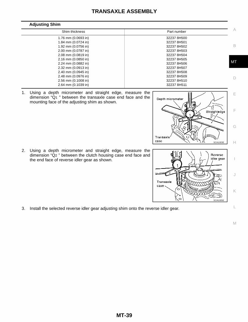
Adjusting Shim
1. Using a depth micrometer and straight edge, measure thedimension “Q1 ” between the transaxle case end face and themounting face of the adjusting shim as shown.
2. Using a depth micrometer and straight edge, measure thedimension “Q2 ” between the clutch housing case end face andthe end face of reverse idler gear as shown.
3. Install the selected reverse idler gear adjusting shim onto the reverse idler gear.
Shim thickness Part number
1.76 mm (0.0693 in)1.84 mm (0.0724 in)1.92 mm (0.0756 in)2.00 mm (0.0787 in)2.08 mm (0.0819 in)2.16 mm (0.0850 in)2.24 mm (0.0882 in)2.32 mm (0.0913 in)2.40 mm (0.0945 in)2.48 mm (0.0976 in)2.56 mm (0.1008 in)2.64 mm (0.1039 in)
32237 8H50032237 8H50132237 8H50232237 8H50332237 8H50432237 8H50532237 8H50632237 8H50732237 8H50832237 8H50932237 8H51032237 8H511
SCIA1003E
SCIA1005E
MT-40
INPUT SHAFT AND GEARS
INPUT SHAFT AND GEARS PFP:32200
Disassembly and Assembly ECS006RP
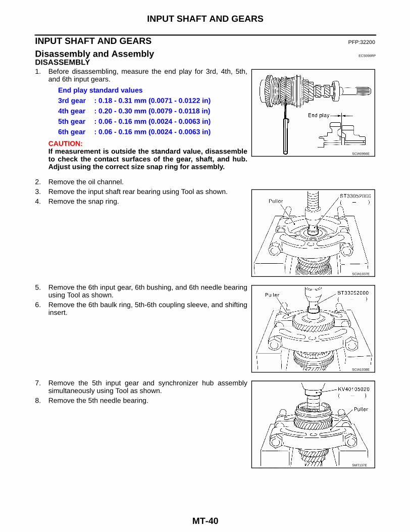
DISASSEMBLY1. Before disassembling, measure the end play for 3rd, 4th, 5th,
and 6th input gears.
CAUTION:If measurement is outside the standard value, disassembleto check the contact surfaces of the gear, shaft, and hub.Adjust using the correct size snap ring for assembly.
2. Remove the oil channel.3. Remove the input shaft rear bearing using Tool as shown.4. Remove the snap ring.
5. Remove the 6th input gear, 6th bushing, and 6th needle bearingusing Tool as shown.
6. Remove the 6th baulk ring, 5th-6th coupling sleeve, and shiftinginsert.
7. Remove the 5th input gear and synchronizer hub assemblysimultaneously using Tool as shown.
8. Remove the 5th needle bearing.
End play standard values3rd gear : 0.18 - 0.31 mm (0.0071 - 0.0122 in)4th gear : 0.20 - 0.30 mm (0.0079 - 0.0118 in)5th gear : 0.06 - 0.16 mm (0.0024 - 0.0063 in)6th gear : 0.06 - 0.16 mm (0.0024 - 0.0063 in)
SCIA0966E
SCIA1037E
SCIA1038E
SMT137E

INPUT SHAFT AND GEARS
MT-41
D
E
F
G
H
I
J
K
L
M
A
B
MT
9. Remove the 5th bushing, thrust washer, 4th input gear, 4th nee-dle bearing, 4th bushing, 4th baulk ring, 3rd-4th synchronizerhub assembly, 3rd baulk ring, and 3rd input gear simultaneouslyusing Tool as shown.
10. Remove the 3rd needle bearing.
11. Remove the input shaft front bearing using Tool as shown.
INSPECTION AFTER DISASSEMBLYInput Shaft and GearInspect the components for the following conditions as shown. Ifnecessary, replace them with new ones.● Damage, peeling, dent, uneven wear, or bending of the input
shaft.● Excessive wear, damage, or peeling of the input gears.
SynchronizerCheck the items below. If necessary, replace them with new ones.● Damage and excessive wear of the contact surfaces of coupling
sleeve, synchronizer hub, and shifting insert.● Coupling sleeve and synchronizer hub must move smoothly as
shown.
SCIA1030E
SCIA0920E
SMT636A
SMT387A

MT-42
INPUT SHAFT AND GEARS
● If any cracks, damage, or excessive wear is found on the camface of baulk ring or working face of the insert as shown, replaceit.
Baulk ring clearance● Press the baulk ring against cone, and measure clearance
between baulk ring and cone. If measurement is below limit,replace it with a new one.
BearingCheck the items below. If necessary, replace them with new ones.● Damage and rough rotation of the bearing as shown.
ASSEMBLY1. Install the 3rd needle bearing.2. Install the 3rd input gear and 3rd baulk ring.3. Install the spread spring, shifting insert, and a new 3rd-4th synchronizer hub onto the 3rd-4th coupling
sleeve.CAUTION:● Install with orientation of the synchronizer hub as shown.● Do not reuse the 3rd-4th synchronizer hub.
SMT867D
Clearance - standard3rd and 4th : 0.9 - 1.45 mm (0.035 - 0.0571 in)5th and 6th : 0.95 - 1.4 mm (0.0374 - 0.055 in)Limit : 0.7 mm (0.028 in)
SMT140
MTF0041D
SCIA0921E

INPUT SHAFT AND GEARS
MT-43
D
E
F
G
H
I
J
K
L
M
A
B
MT
● Install with orientation of coupling sleeve as shown.
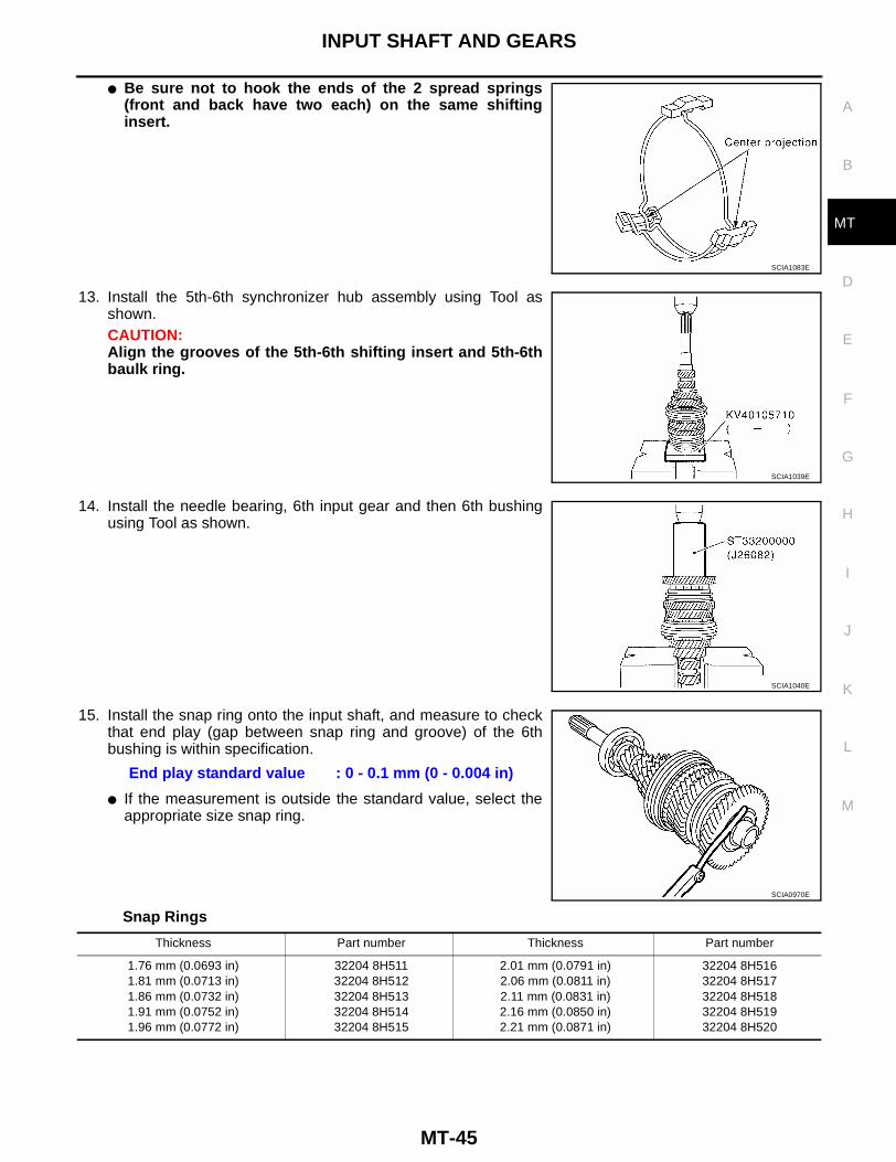
● Be sure not to hook the ends of the 2 spread springs(front and back have two each) on the same shiftinginsert.
4. Install 3rd-4th synchronizer hub assembly using Tool as shown.CAUTION:Align grooves of shifting insert and 3rd baulk ring.
5. Install the 4th bushing using Tool as shown.6. Install the 4th baulk ring.7. Install the 4th input gear and 4th needle bearing.
SCIA0993E
SCIA1083E
SCIA1031E
SCIA1032E

MT-44
INPUT SHAFT AND GEARS
8. Measure the dimension “C2 ” as shown. Select a thrust washerso that dimension “C2 ” satisfies standard dimension specifica-tion. Then install the thrust washer onto the input shaft.
CAUTION:Only 1 thrust washer can be selected.
Thrust Washer
9. Install the 5th bushing using Tool as shown.10. Install the 5th needle bearing and 5th input gear.11. Install the 5th baulk ring.
12. Install the synchronizer assembly onto a new 5th-6th synchro-nizer hub.CAUTION:● Install with the orientation of the synchronizer hub as
shown.● Do not reuse the 5th-6th synchronizer hub.
Standard for dimension “C2 ” : 154.7 - 154.8 mm (6.091 - 6.094 in)
SCIA0925E
Thickness Part number Thickness Part number
3.84 mm (0.1512 in)3.90 mm (0.1535 in)3.96 mm (0.1559 in)
32347 8H50032347 8H50132347 8H502
4.02 mm (0.1583 in)4.08 mm (0.1606 in)4.14 mm (0.1630 in)
32347 8H50332347 8H50432347 8H505
SCIA1033E
SCIA0921E
INPUT SHAFT AND GEARS
MT-45
D
E
F
G
H
I
J
K
L
M
A
B
MT
● Be sure not to hook the ends of the 2 spread springs(front and back have two each) on the same shiftinginsert.
13. Install the 5th-6th synchronizer hub assembly using Tool asshown.CAUTION:Align the grooves of the 5th-6th shifting insert and 5th-6thbaulk ring.
14. Install the needle bearing, 6th input gear and then 6th bushingusing Tool as shown.
15. Install the snap ring onto the input shaft, and measure to checkthat end play (gap between snap ring and groove) of the 6thbushing is within specification.
● If the measurement is outside the standard value, select theappropriate size snap ring.
Snap Rings
SCIA1083E
SCIA1039E
SCIA1040E
End play standard value : 0 - 0.1 mm (0 - 0.004 in)
SCIA0970E
Thickness Part number Thickness Part number
1.76 mm (0.0693 in)1.81 mm (0.0713 in)1.86 mm (0.0732 in)1.91 mm (0.0752 in)1.96 mm (0.0772 in)
32204 8H51132204 8H51232204 8H51332204 8H51432204 8H515
2.01 mm (0.0791 in)2.06 mm (0.0811 in)2.11 mm (0.0831 in)2.16 mm (0.0850 in)2.21 mm (0.0871 in)
32204 8H51632204 8H51732204 8H51832204 8H51932204 8H520
MT-46
INPUT SHAFT AND GEARS
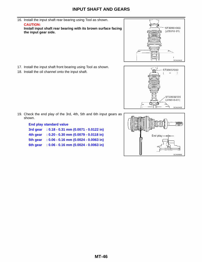
16. Install the input shaft rear bearing using Tool as shown.CAUTION:Install input shaft rear bearing with its brown surface facingthe input gear side.
17. Install the input shaft front bearing using Tool as shown.18. Install the oil channel onto the input shaft.
19. Check the end play of the 3rd, 4th, 5th and 6th input gears asshown.
SCIA1041E
SCIA1042E
End play standard value3rd gear : 0.18 - 0.31 mm (0.0071 - 0.0122 in)4th gear : 0.20 - 0.30 mm (0.0079 - 0.0118 in)5th gear : 0.06 - 0.16 mm (0.0024 - 0.0063 in)6th gear : 0.06 - 0.16 mm (0.0024 - 0.0063 in)
SCIA0966E

MAINSHAFT AND GEARS
MT-47
D
E
F
G
H
I
J
K
L
M
A
B
MT
MAINSHAFT AND GEARS PFP:32241
Disassembly and Assembly ECS006RQ
DISASSEMBLY1. Before disassembling, measure the end play of 1st and 2nd
main gears as shown.
CAUTION:If the measurement is outside the standard value, disas-semble to check the contact surfaces of gear, shaft, andhub. Adjust with the snap ring at assembly.
2. Remove the snap ring.3. Remove the C-ring holder, and then mainshaft C-ring as shown.
4. Remove the mainshaft rear bearing, adjust shim, and 6th maingear using Tool as shown.
5. Remove the 5th-6th mainshaft spacer.
6. Remove the 4th main gear and 5th main gear simultaneouslyusing Tool as shown.
7. Remove the adjusting shim.8. Remove the 3rd-4th mainshaft spacer.
End play standard value1st gear : 0.20 - 0.30 mm (0.0079 - 0.0118 in)2nd gear : 0.06 - 0.16 mm (0.0024 - 0.0063 in)
SCIA0973E
SCIA0974E
SCIA1056E
SCIA1044E

MT-48
MAINSHAFT AND GEARS
9. Remove the 3rd main gear, 2nd main gear, 2nd gear needlebearing, 2nd bushing, 1st-2nd synchronizer assembly, 1st maingear, reverse main gear, 1st gear needle bearing, and 1st bush-ing simultaneously using Tool as shown.
INSPECTION AFTER DISASSEMBLYMainshaft and GearsCheck the items listed as shown. If necessary, replace them withnew ones.● Damage, peeling, dent, uneven wear, bending, and other non-
standard conditions of the mainshaft.● Excessive wear, damage, peeling, and other non-standard con-
ditions of the mainshaft gears.
SynchronizerCheck the items listed as shown. If necessary, replace them withnew ones.● Damage, unusual wear on contact surfaces of coupling sleeve,
synchronizer hub, and shifting insert.● Coupling sleeve and synchronizer hub must move smoothly as
shown.
● If any cracks, damage, or excessive wear is found on the camface of baulk ring or working face of the insert, replace it.
SCIA1045E
SMT640A
SMT387A
SMT867D
MAINSHAFT AND GEARS
MT-49
D
E
F
G
H
I
J
K
L
M
A
B
MT
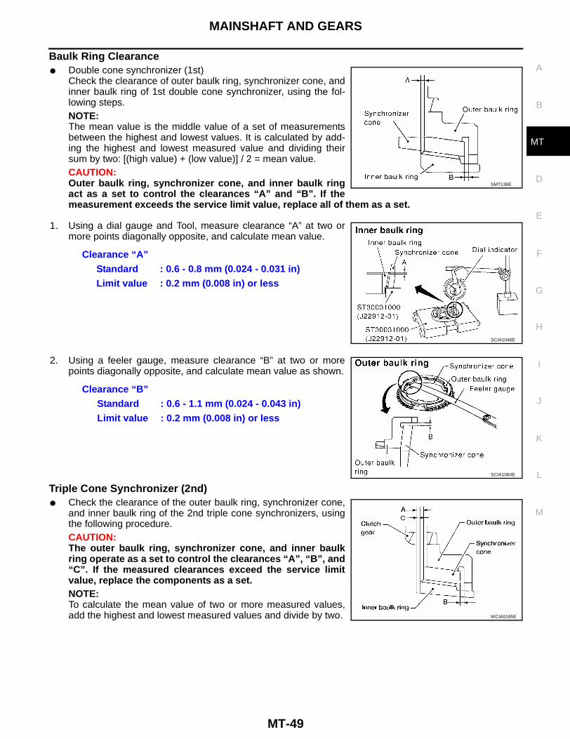
Baulk Ring Clearance● Double cone synchronizer (1st)
Check the clearance of outer baulk ring, synchronizer cone, andinner baulk ring of 1st double cone synchronizer, using the fol-lowing steps.NOTE:The mean value is the middle value of a set of measurementsbetween the highest and lowest values. It is calculated by add-ing the highest and lowest measured value and dividing theirsum by two: [(high value) + (low value)] / 2 = mean value.CAUTION:Outer baulk ring, synchronizer cone, and inner baulk ringact as a set to control the clearances “A” and “B”. If themeasurement exceeds the service limit value, replace all of them as a set.
1. Using a dial gauge and Tool, measure clearance “A” at two ormore points diagonally opposite, and calculate mean value.
2. Using a feeler gauge, measure clearance “B” at two or morepoints diagonally opposite, and calculate mean value as shown.
Triple Cone Synchronizer (2nd)● Check the clearance of the outer baulk ring, synchronizer cone,
and inner baulk ring of the 2nd triple cone synchronizers, usingthe following procedure.CAUTION:The outer baulk ring, synchronizer cone, and inner baulkring operate as a set to control the clearances “A”, “B”, and“C”. If the measured clearances exceed the service limitvalue, replace the components as a set.NOTE:To calculate the mean value of two or more measured values,add the highest and lowest measured values and divide by two.
SMT138E
Clearance “A”Standard : 0.6 - 0.8 mm (0.024 - 0.031 in)Limit value : 0.2 mm (0.008 in) or less
SCIA1046E
Clearance “B”Standard : 0.6 - 1.1 mm (0.024 - 0.043 in)Limit value : 0.2 mm (0.008 in) or less
SCIA1084E
WCIA0195E

MT-50
MAINSHAFT AND GEARS
1. Press the baulk ring on to the clutch gear taper cone by hand,then measure the clearance “A” at two or more points diagonallyopposite with a feeler gauge, and then calculate the mean value.
2. Measure clearances “B” at two or more points diagonally oppo-site with a feeler gauge, and then calculate the mean value.
3. Press the baulk ring on to the clutch gear taper cone by hand,then measure the clearance “C” at two or more points diagonallyopposite with a feeler gauge, and then calculate the mean value.
BearingCheck the items below. If necessary, replace them with new ones.● Damage and rough rotation of the bearing as shown.
Clearance “A”Standard : 0.6 - 1.2 mm (0.024 - 0.047 in)Limit : 0.3 mm (0.012 in)
LCIA0298E
Clearance “B”Standard : 0.6 - 1.1 mm (0.024 - 0.043 in)Limit : 0.2 mm (0.008 in)
SCIA1084E
Clearance “C”Standard : 0.7 - 1.1 mm (0.028 - 0.043 in)Limit : 0.3 mm (0.012 in)
LCIA0300E
MTF0041D
MAINSHAFT AND GEARS
MT-51
D
E
F
G
H
I
J
K
L
M
A
B
MT
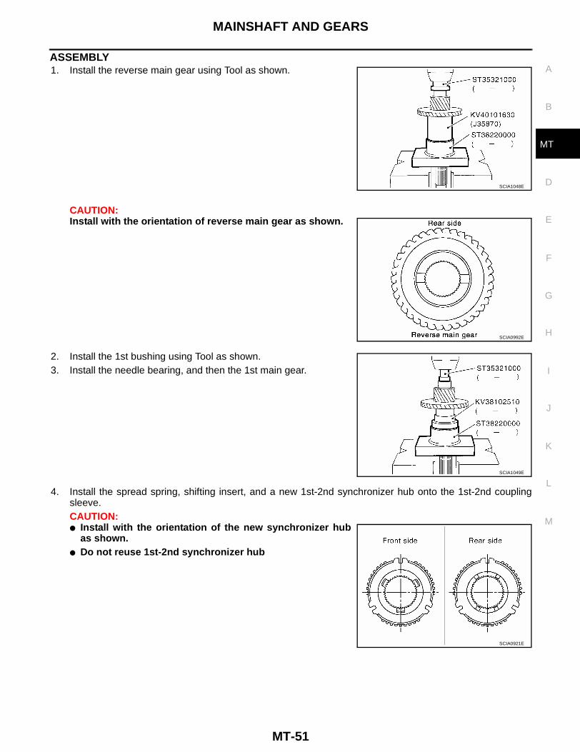
ASSEMBLY1. Install the reverse main gear using Tool as shown.
CAUTION:Install with the orientation of reverse main gear as shown.
2. Install the 1st bushing using Tool as shown.3. Install the needle bearing, and then the 1st main gear.
4. Install the spread spring, shifting insert, and a new 1st-2nd synchronizer hub onto the 1st-2nd couplingsleeve.CAUTION:● Install with the orientation of the new synchronizer hub
as shown.● Do not reuse 1st-2nd synchronizer hub
SCIA1048E
SCIA0992E
SCIA1049E
SCIA0921E

MT-52
MAINSHAFT AND GEARS
● Install with the orientation of coupling sleeve as shown.
● Do not hook the ends of the two spread springs (frontand back have two each) on the same shifting insert.
5. Install the 1st gear synchronizer assembly onto the mainshaft,and the synchronizer hub assembly onto the mainshaft usingTool as shown.CAUTION:● Outer baulk ring, synchronizer cone, and inner baulk ring
on the 2nd gear-side must have been removed.● Install the coupling sleeve with the proper orientation.
6. Install the 2nd bushing using Tool as shown.7. Install the outer baulk ring, synchronizer cone, and inner baulk
ring on 2nd gear-side.8. Install the 2nd needle bearing and 2nd gear.
9. Install the 3rd main gear.CAUTION:Install the 3rd main gear with the orientation as shown.
10. Install the 3rd-4th mainshaft spacer.
SCIA0989E
SCIA1083E
SCIA1050E
SCIA1051E
SCIA1052E
MAINSHAFT AND GEARS
MT-53
D
E
F
G
H
I
J
K
L
M
A
B
MT
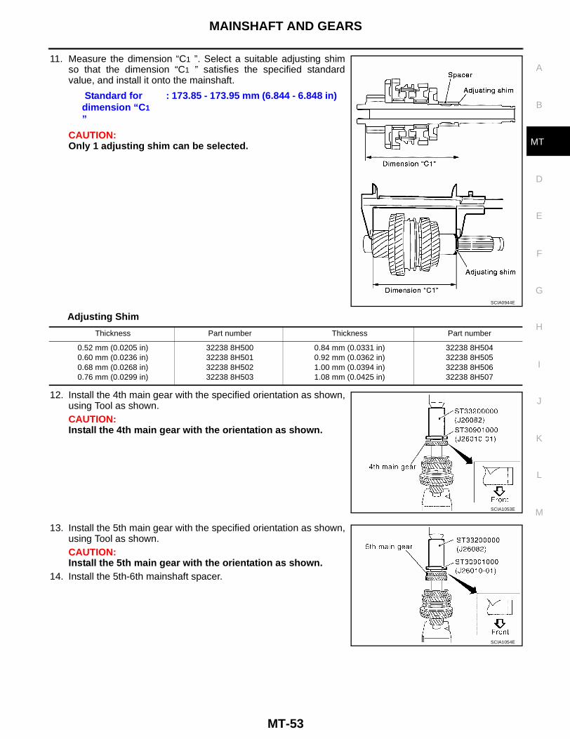
11. Measure the dimension “C1 ”. Select a suitable adjusting shimso that the dimension “C1 ” satisfies the specified standardvalue, and install it onto the mainshaft.
CAUTION:Only 1 adjusting shim can be selected.
Adjusting Shim
12. Install the 4th main gear with the specified orientation as shown,using Tool as shown.CAUTION:Install the 4th main gear with the orientation as shown.
13. Install the 5th main gear with the specified orientation as shown,using Tool as shown.CAUTION:Install the 5th main gear with the orientation as shown.
14. Install the 5th-6th mainshaft spacer.
Standard for dimension “C1 ”
: 173.85 - 173.95 mm (6.844 - 6.848 in)
SCIA0944E
Thickness Part number Thickness Part number
0.52 mm (0.0205 in)0.60 mm (0.0236 in)0.68 mm (0.0268 in)0.76 mm (0.0299 in)
32238 8H50032238 8H50132238 8H50232238 8H503
0.84 mm (0.0331 in)0.92 mm (0.0362 in)1.00 mm (0.0394 in)1.08 mm (0.0425 in)
32238 8H50432238 8H50532238 8H50632238 8H507
SCIA1053E
SCIA1054E

MT-54
MAINSHAFT AND GEARS
15. Install the 6th main gear using Tool as shown.
16. Select the 6th main adjusting shim and then install it onto the mainshaft.● Calculate thickness “S” of 6th main adjusting shim by proce-
dure below so that end play dimension between 6th maingear and mainshaft rear bearing becomes the dimensionspecified.
CAUTION:Only 1 adjusting shim can be selected.
Adjusting Shim
a. Using a height gauge, measure the dimension “S1 ” and “S2 ” as shown.b. Install the selected 6th main adjusting shim to the mainshaft.17. Install the mainshaft rear bearing using Tool as shown.
SCIA1057E
End play : 0 - 0.1 mm (0 - 0.004 in)Dimension “S” = (“S1 ” - “S2 ”) + End play
“S” : Thickness of adjusting shim“S1 ”
: Dimension from mainshaft standard face to mainshaft rear bearing press-fit end face
“S2 ”
: Dimension from mainshaft standard face to 6th main gear end face
SCIA0995E
Thickness Part number Thickness Part number
0.88 mm (0.0346 in)0.96 mm (0.0378 in)1.04 mm (0.0409 in)1.12 mm (0.0441 in)
32237 8H56032237 8H56132237 8H56232237 8H563
1.20 mm (0.0472 in)1.28 mm (0.0504 in)1.36 mm (0.0535 in)
32237 8H56432237 8H56532237 8H566
SCIA1058E

MAINSHAFT AND GEARS
MT-55
D
E
F
G
H
I
J
K
L
M
A
B
MT
18. Install the C-ring onto the mainshaft, and check that the end playof mainshaft rear bearing meets specifications.
● If the measurement is outside the specified standard value,reselect a new C-ring.
C-Ring
19. Fit the C-ring holder, and install the snap ring as shown.
20. Check the end play of 1st and 2nd main gears as shown.
End play standard value : 0 - 0.06 mm (0 - 0.0024 in)
SCIA0979E
Thickness Part number Thickness Part number
2.535 mm (0.0866 in)2.565 mm (0.1010 in)2.595 mm (0.1022 in)2.625 mm (0.1033 in)2.655 mm (0.1045 in)2.685 mm (0.1057 in)2.715 mm (0.1069 in)2.745 mm (0.1081 in)2.775 mm (0.1093 in)2.805 mm (0.1104 in)
32348 8H80032348 8H80132348 8H80232348 8H80332348 8H80432348 8H80532348 8H80632348 8H80732348 8H80832348 8H809
2.835 mm (0.1116 in)2.865 mm (0.1128 in)2.895 mm (0.1140 in)2.925 mm (0.1152 in)2.955 mm (0.1163 in)2.985 mm (0.1175 in)3.015 mm (0.1187 in)3.045 mm (0.1199 in)3.075 mm (0.1211 in)
32348 8H81032348 8H81132348 8H81232348 8H81332348 8H81432348 8H81532348 8H81632348 8H81732348 8H818
SCIA0974E
End play standard value1st gear : 0.20 - 0.30 mm (0.0079 - 0.0118 in)2nd gear : 0.06 - 0.16 mm (0.0024 - 0.0063 in)
SCIA0973E
MT-56
REVERSE IDLER SHAFT AND GEARS
REVERSE IDLER SHAFT AND GEARS PFP:32281
Disassembly and Assembly ECS006RR
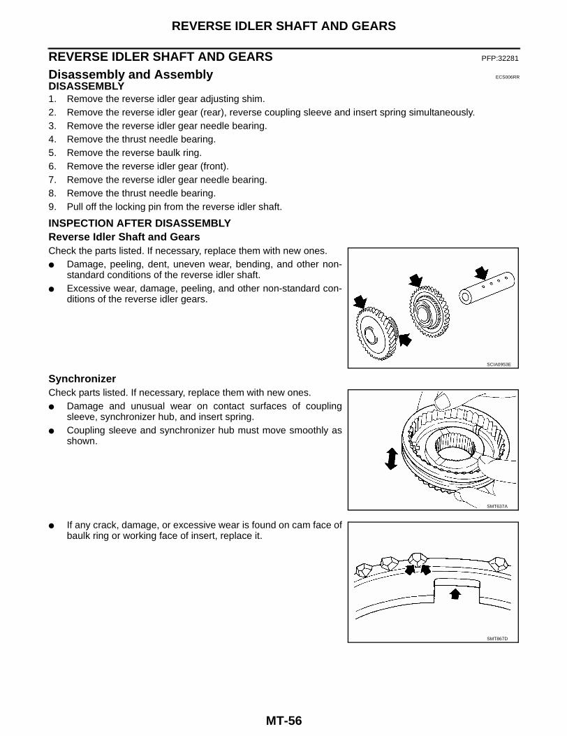
DISASSEMBLY1. Remove the reverse idler gear adjusting shim.2. Remove the reverse idler gear (rear), reverse coupling sleeve and insert spring simultaneously.3. Remove the reverse idler gear needle bearing.4. Remove the thrust needle bearing.5. Remove the reverse baulk ring.6. Remove the reverse idler gear (front).7. Remove the reverse idler gear needle bearing.8. Remove the thrust needle bearing.9. Pull off the locking pin from the reverse idler shaft.
INSPECTION AFTER DISASSEMBLYReverse Idler Shaft and GearsCheck the parts listed. If necessary, replace them with new ones.● Damage, peeling, dent, uneven wear, bending, and other non-
standard conditions of the reverse idler shaft.● Excessive wear, damage, peeling, and other non-standard con-
ditions of the reverse idler gears.
SynchronizerCheck parts listed. If necessary, replace them with new ones.● Damage and unusual wear on contact surfaces of coupling
sleeve, synchronizer hub, and insert spring.● Coupling sleeve and synchronizer hub must move smoothly as
shown.
● If any crack, damage, or excessive wear is found on cam face ofbaulk ring or working face of insert, replace it.
SCIA0953E
SMT637A
SMT867D

REVERSE IDLER SHAFT AND GEARS
MT-57
D
E
F
G
H
I
J
K
L
M
A
B
MT
Baulk ring clearance● Press the baulk ring against the cone, and measure the clear-
ance between the baulk ring and cone as shown. If the mea-surement is below the specified limit, replace it with a new one.
BearingCheck the parts listed. If necessary, replace them with new ones.● Damage and rough rotation of the bearing.
ASSEMBLYAssembly is in the reverse order of disassembly.CAUTION:● Install the insert spring with the orientation as shown.
Baulk ring to gear clearanceStandard : 0.95 - 1.4 mm (0.0374 - 0.055 in)Limit value : 0.7 mm (0.028 in)
SMT140
SCIA0954E

MT-58
FINAL DRIVE (RS6F51A)
FINAL DRIVE (RS6F51A) PFP:38411
Disassembly and Assembly ECS006S6
PRE-INSPECTION1. Clean final drive assembly sufficiently to prevent side gear thrust washer, differential case, side gear, and
other parts from sticking by gear oil.2. Upright the differential case so that the side gear to be measured faces upward.3. Place final drive adapter and dial indicator onto side gear using
Tool as shown.
4. Move side gear up and down, and measure the clearance asshown.
CAUTION:There must be no resistance and the gears must rotatefreely.
5. If the clearance measured is not within specification, adjust the clearance by changing the thrust washerthickness.
6. Turn the differential case upside down, and measure the clearance between the side gear and differentialcase on the other side to the same specifications, adjust using a thrust washer as necessary.
DISASSEMBLY1. Remove the mounting bolts and then separate the final gear from the differential case.2. Remove speedometer drive gear.3. Using Tool and puller, remove differential side bearing (clutch
housing side) as shown.
WCIA0143E
Clearance between side gear and differential case
: 0.1 - 0.2 mm (0.004 - 0.008 in)
SMT611A
SCIA1019E

FINAL DRIVE (RS6F51A)
MT-59
D
E
F
G
H
I
J
K
L
M
A
B
MT
4. Using Tool and puller, remove differential side bearing (transaxlecase side) as shown.
5. Using a pin punch, pull out lock pin and pinion mate shaft asshown.
6. Rotate pinion mate gears, and remove pinion mate gears, pinion mate thrust washers, side gears, andside gear thrust washers from differential case.
INSPECTION AFTER DISASSEMBLYGear, Washer, Shaft and CaseCheck side gears, side gear thrust washers, pinion mate shaft, pin-ion mate gears, pinion mate thrust washers and differential case asshown. If necessary, replace with new parts.
BearingCheck for bearing damage and rough rotation as shown. If neces-sary, replace with new parts.CAUTION:When replacing tapered roller bearing, replace outer and innerraces as a set.
ASSEMBLY1. Apply gear oil to sliding area of differential case, each gear, and thrust washer.
SCIA1060E
SCIA0908E
MTK0135D
SPD715
MT-60
FINAL DRIVE (RS6F51A)
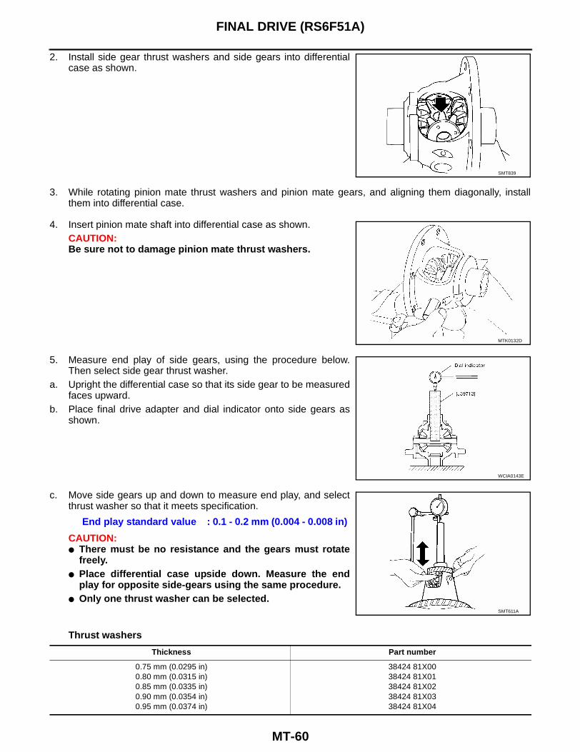
2. Install side gear thrust washers and side gears into differentialcase as shown.
3. While rotating pinion mate thrust washers and pinion mate gears, and aligning them diagonally, installthem into differential case.
4. Insert pinion mate shaft into differential case as shown.CAUTION:Be sure not to damage pinion mate thrust washers.
5. Measure end play of side gears, using the procedure below.Then select side gear thrust washer.
a. Upright the differential case so that its side gear to be measuredfaces upward.
b. Place final drive adapter and dial indicator onto side gears asshown.
c. Move side gears up and down to measure end play, and selectthrust washer so that it meets specification.
CAUTION:● There must be no resistance and the gears must rotate
freely.● Place differential case upside down. Measure the end
play for opposite side-gears using the same procedure. ● Only one thrust washer can be selected.
Thrust washers
SMT839
MTK0132D
WCIA0143E
End play standard value : 0.1 - 0.2 mm (0.004 - 0.008 in)
SMT611A
Thickness Part number
0.75 mm (0.0295 in)0.80 mm (0.0315 in)0.85 mm (0.0335 in)0.90 mm (0.0354 in)0.95 mm (0.0374 in)
38424 81X0038424 81X0138424 81X0238424 81X0338424 81X04

FINAL DRIVE (RS6F51A)
MT-61
D
E
F
G
H
I
J
K
L
M
A
B
MT
6. Drive a new lock pin into the pinion mate shaft using a pin punchas shown.CAUTION:Do not reuse the lock pin.
7. Install differential side bearing (transaxle case side) using Toolas shown.
8. Align and install speedometer drive gear onto differential caseas shown.
9. Install differential side bearing (clutch housing side) using Toolas shown.
10. Install the final gear into the differential case, and tighten thefinal gear bolts to specification.
SCIA0908E
SCIA1061E
SMT842D
SCIA1018E
Final gear bolts : 122.5 - 137.5 N·m (13 - 14 kg-m, 91 - 101 ft-lb)
SCIA0912E

MT-62
FINAL DRIVE (RS6F51H)
FINAL DRIVE (RS6F51H) PFP:38411
Disassembly and Assembly ECS006RS
DISASSEMBLY1. Remove the mounting bolts. Then, separate the final gear from the differential case.2. Remove the speedometer drive gear.3. Using a puller and Tool (drift), remove the differential side bear-
ing (clutch housing side) as shown.
4. Using a puller and Tool (drift), remove the differential side bear-ing (transaxle case side) as shown.
INSPECTION AFTER DISASSEMBLYBearingCheck for bearing damage and rough rotation as shown. If neces-sary, replace with a new one.CAUTION:When replacing the tapered roller bearing, replace the outer andinner races as a set.
ASSEMBLY1. Using Tool (drift), install the differential side bearing (transaxle
case side) as shown.
SCIA1019E
SCIA1060E
SPD715
SCIA1061E

FINAL DRIVE (RS6F51H)
MT-63
D
E
F
G
H
I
J
K
L
M
A
B
MT
2. Align and install the speedometer drive gear onto the differentialcase as shown.
3. Using Tool (drift), install the differential side bearing (clutchhousing side) as shown.
4. Install the final gear into the differential case, and tighten thefinal gear bolts to specification.
SMT842D
SCIA1018E
Final gear bolts : 122.5 - 137.5 N·m (13 - 14 kg-m, 91 - 101 ft-lb)
SCIA0912E

MT-64
SHIFT CONTROL
SHIFT CONTROL PFP:32982
Inspection ECS006RT
● Check the contact surfaces and sliding area for wear, damage,or bending as shown. If necessary, replace the parts.
SHIFT FORK● Check if the width of the shift fork hook (sliding area with cou-
pling sleeve) is within specification, as shown.
Shift Fork
SCIA0913E
SMT801D
Item One-side wear specification Sliding width of new part
1st & 2nd 0.2 mm (0.008 in)7.80 - 7.93 mm
(0.3071 - 0.3122 in)
3rd & 4th 0.2 mm (0.008 in)7.80 - 7.93 mm
(0.3071 - 0.3122 in)
5th & 6th 0.2 mm (0.008 in)6.10 - 6.23 mm
(0.2402 - 0.2453 in)
Reverse 0.2 mm (0.008 in)12.80 - 12.93 mm
(0.5039 - 0.5091 in)
SERVICE DATA AND SPECIFICATIONS (SDS)
MT-65
D
E
F
G
H
I
J
K
L
M
A
B
MT
SERVICE DATA AND SPECIFICATIONS (SDS) PFP:00030
General Specifications ECS006RU
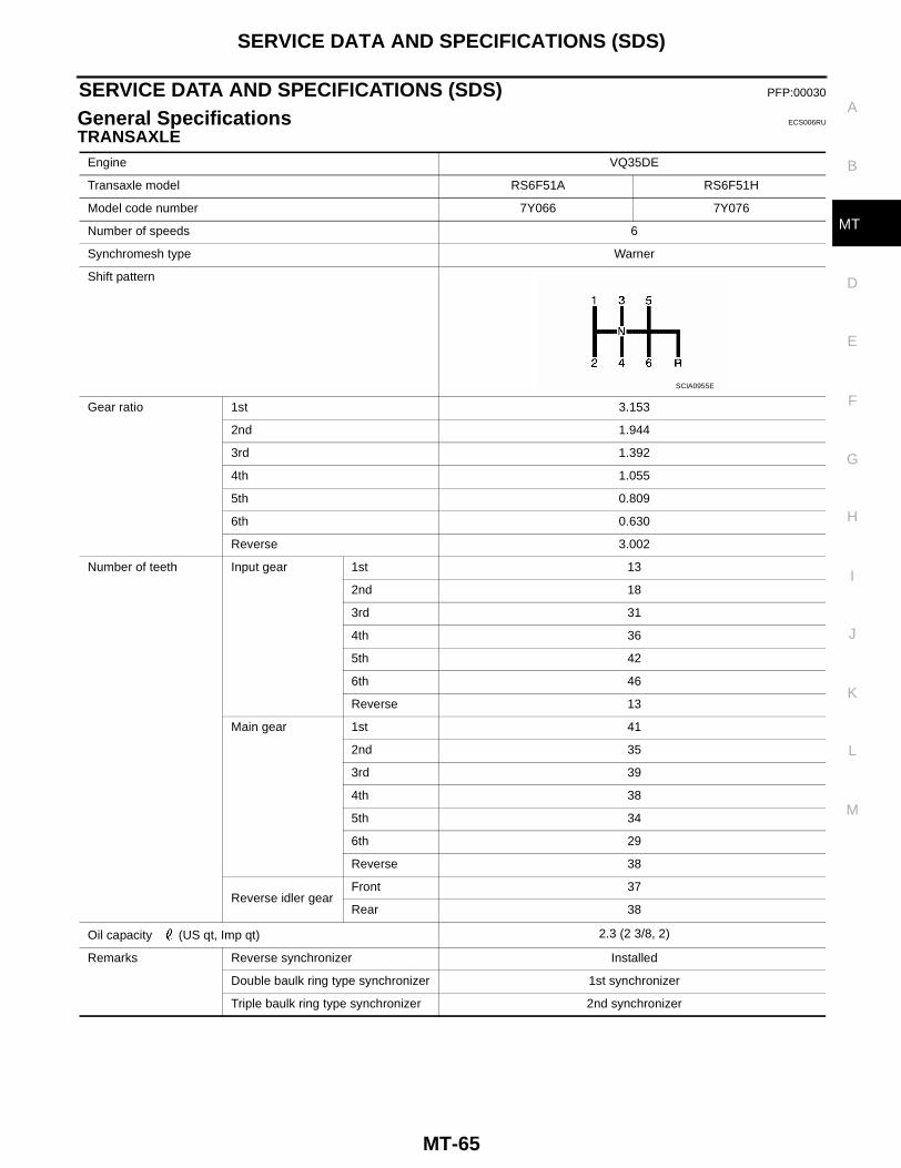
TRANSAXLEEngine VQ35DE
Transaxle model RS6F51A RS6F51H
Model code number 7Y066 7Y076
Number of speeds 6
Synchromesh type Warner
Shift pattern
Gear ratio 1st 3.153
2nd 1.944
3rd 1.392
4th 1.055
5th 0.809
6th 0.630
Reverse 3.002
Number of teeth Input gear 1st 13
2nd 18
3rd 31
4th 36
5th 42
6th 46
Reverse 13
Main gear 1st 41
2nd 35
3rd 39
4th 38
5th 34
6th 29
Reverse 38
Reverse idler gear Front 37
Rear 38
Oil capacity (US qt, Imp qt) 2.3 (2 3/8, 2)
Remarks Reverse synchronizer Installed
Double baulk ring type synchronizer 1st synchronizer
Triple baulk ring type synchronizer 2nd synchronizer
SCIA0955E
MT-66
SERVICE DATA AND SPECIFICATIONS (SDS)
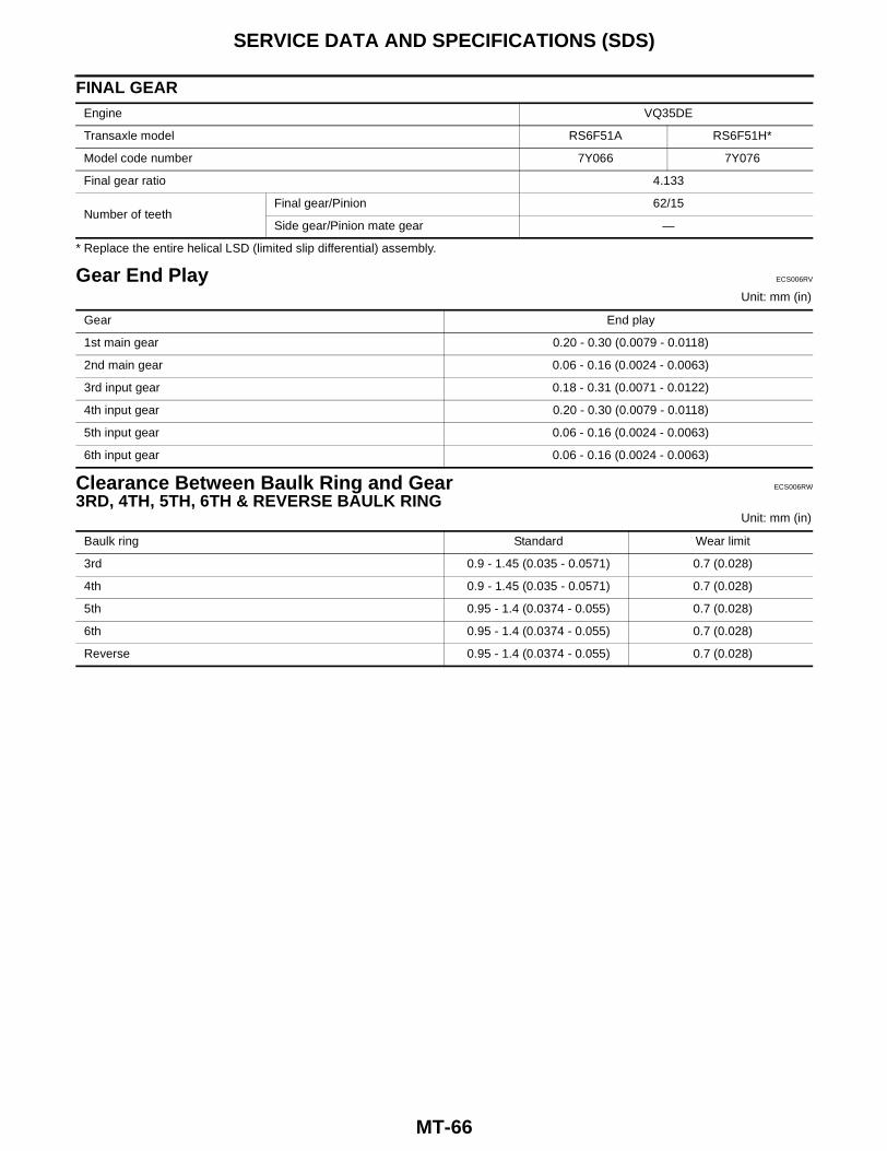
FINAL GEAR
* Replace the entire helical LSD (limited slip differential) assembly.
Gear End Play ECS006RV
Unit: mm (in)
Clearance Between Baulk Ring and Gear ECS006RW
3RD, 4TH, 5TH, 6TH & REVERSE BAULK RINGUnit: mm (in)
Engine VQ35DE
Transaxle model RS6F51A RS6F51H*
Model code number 7Y066 7Y076
Final gear ratio 4.133
Number of teethFinal gear/Pinion 62/15
Side gear/Pinion mate gear —
Gear End play
1st main gear 0.20 - 0.30 (0.0079 - 0.0118)
2nd main gear 0.06 - 0.16 (0.0024 - 0.0063)
3rd input gear 0.18 - 0.31 (0.0071 - 0.0122)
4th input gear 0.20 - 0.30 (0.0079 - 0.0118)
5th input gear 0.06 - 0.16 (0.0024 - 0.0063)
6th input gear 0.06 - 0.16 (0.0024 - 0.0063)
Baulk ring Standard Wear limit
3rd 0.9 - 1.45 (0.035 - 0.0571) 0.7 (0.028)
4th 0.9 - 1.45 (0.035 - 0.0571) 0.7 (0.028)
5th 0.95 - 1.4 (0.0374 - 0.055) 0.7 (0.028)
6th 0.95 - 1.4 (0.0374 - 0.055) 0.7 (0.028)
Reverse 0.95 - 1.4 (0.0374 - 0.055) 0.7 (0.028)
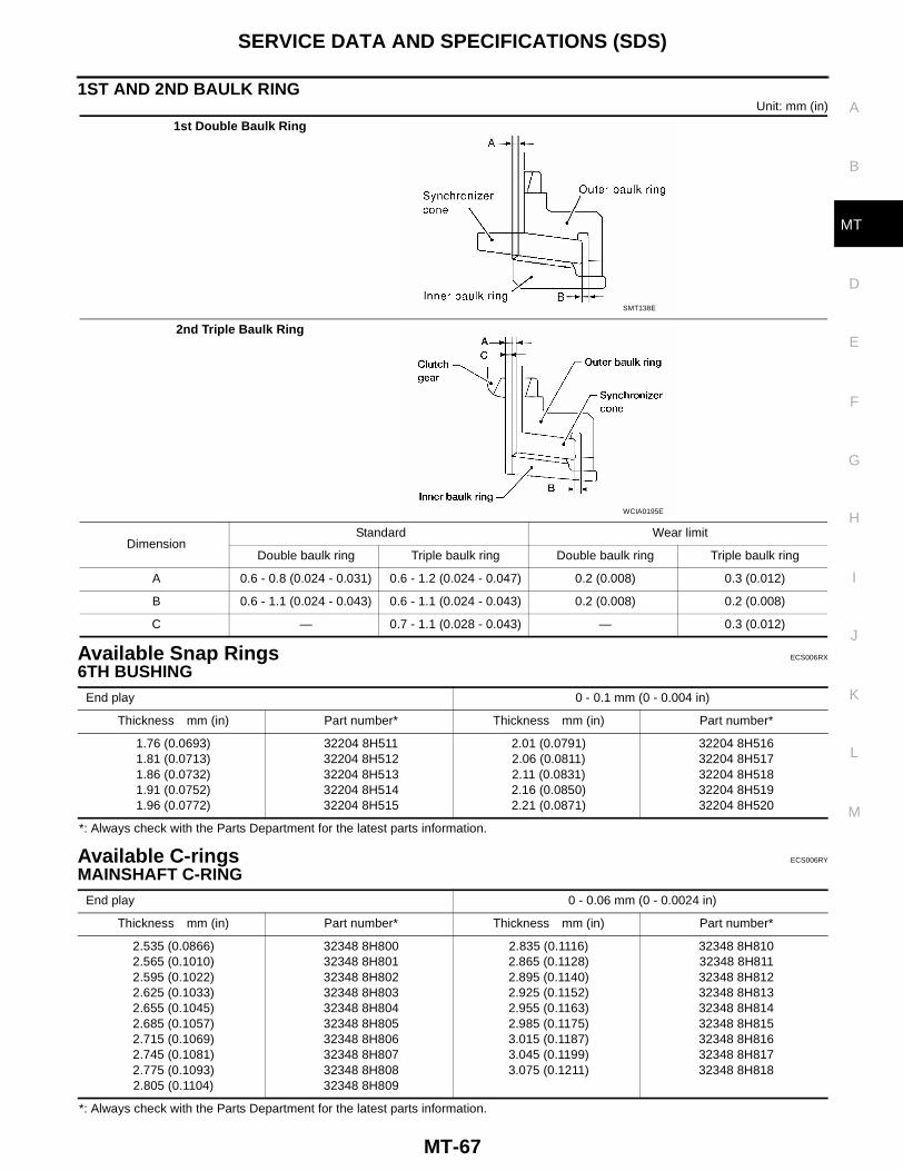
SERVICE DATA AND SPECIFICATIONS (SDS)
MT-67
D
E
F
G
H
I
J
K
L
M
A
B
MT
1ST AND 2ND BAULK RINGUnit: mm (in)
Available Snap Rings ECS006RX
6TH BUSHING
*: Always check with the Parts Department for the latest parts information.
Available C-rings ECS006RY
MAINSHAFT C-RING
*: Always check with the Parts Department for the latest parts information.
1st Double Baulk Ring
2nd Triple Baulk Ring
DimensionStandard Wear limit
Double baulk ring Triple baulk ring Double baulk ring Triple baulk ring
A 0.6 - 0.8 (0.024 - 0.031) 0.6 - 1.2 (0.024 - 0.047) 0.2 (0.008) 0.3 (0.012)
B 0.6 - 1.1 (0.024 - 0.043) 0.6 - 1.1 (0.024 - 0.043) 0.2 (0.008) 0.2 (0.008)
C — 0.7 - 1.1 (0.028 - 0.043) — 0.3 (0.012)
SMT138E
WCIA0195E
End play 0 - 0.1 mm (0 - 0.004 in)
Thickness mm (in) Part number* Thickness mm (in) Part number*
1.76 (0.0693)1.81 (0.0713)1.86 (0.0732)1.91 (0.0752)1.96 (0.0772)
32204 8H51132204 8H51232204 8H51332204 8H51432204 8H515
2.01 (0.0791)2.06 (0.0811)2.11 (0.0831)2.16 (0.0850)2.21 (0.0871)
32204 8H51632204 8H51732204 8H51832204 8H51932204 8H520
End play 0 - 0.06 mm (0 - 0.0024 in)
Thickness mm (in) Part number* Thickness mm (in) Part number*
2.535 (0.0866)2.565 (0.1010)2.595 (0.1022)2.625 (0.1033)2.655 (0.1045)2.685 (0.1057)2.715 (0.1069)2.745 (0.1081)2.775 (0.1093)2.805 (0.1104)
32348 8H80032348 8H80132348 8H80232348 8H80332348 8H80432348 8H80532348 8H80632348 8H80732348 8H80832348 8H809
2.835 (0.1116)2.865 (0.1128)2.895 (0.1140)2.925 (0.1152)2.955 (0.1163)2.985 (0.1175)3.015 (0.1187)3.045 (0.1199)3.075 (0.1211)
32348 8H81032348 8H81132348 8H81232348 8H81332348 8H81432348 8H81532348 8H81632348 8H81732348 8H818

MT-68
SERVICE DATA AND SPECIFICATIONS (SDS)
Available Thrust Washers ECS006RZ
INPUT SHAFT THRUST WASHER
*: Always check with the Parts Department for the latest parts information.
Available Adjusting Shims ECS006S0
MAINSHAFT ADJUSTING SHIM
*: Always check with the Parts Department for the latest parts information.
INPUT SHAFT REAR BEARING ADJUSTING SHIM
Standard length “C2” 154.7 - 154.8 mm (6.091 - 6.094in)
Thickness mm (in) Part number* Thickness mm (in) Part number*
3.84 (0.1512)3.90 (0.1535)3.96 (0.1559)
32347 8H50032347 8H50132347 8H502
4.02 (0.1583)4.08 (0.1606)4.14 (0.1630)
32347 8H50332347 8H50432347 8H505
SCIA1008E
Standard length “C1” 173.85 - 173.95 mm (6.844 - 6.848in)
Thickness mm (in) Part number* Thickness mm (in) Part number*
0.52 (0.0205)0.60 (0.0236)0.68 (0.0268)0.76 (0.0299)
32238 8H50032238 8H50132238 8H50232238 8H503
0.84 (0.0331)0.92 (0.0362)1.00 (0.0394)1.08 (0.0425)
32238 8H50432238 8H50532238 8H50632238 8H507
SCIA1009E
End play 0 - 0.06 mm (0 - 0.0024 in)
Thickness mm (in) Part number* Thickness mm (in) Part number* Thickness mm (in) Part number*
0.40 (0.0157)0.44 (0.0173)0.48 (0.0189)0.52 (0.0205)0.56 (0.0220)0.60 (0.0236)0.64 (0.0252)6.68 (0.0268)0.72 (0.0283)0.76 (0.0299)0.80 (0.0315)0.84 (0.0331)
32225 8H50032225 8H50132225 8H50232225 8H50332225 8H50432225 8H50532225 8H50632225 8H50732225 8H50832225 8H50932225 8H51032225 8H511
0.88 (0.0346)0.92 (0.0362)0.96 (0.0378)1.00 (0.0396)1.04 (0.0409)1.08 (0.0425)1.12 (0.0441)1.16 (0.0457)1.20 (0.0472)1.24 (0.0488)1.28 (0.0504)1.32 (0.0520)
32225 8H51232225 8H51332225 8H51432225 8H51532225 8H51632225 8H51732225 8H51832225 8H51932225 8H52032225 8H52132225 8H52232225 8H523
1.36 (0.0520)1.40 (0.0551)1.44 (0.0567)1.48 (0.0583)1.52 (0.0598)1.56 (0.0614)1.60 (0.0630)1.64 (0.0646)
32225 8H52432225 8H56032225 8H56132225 8H56232225 8H56332225 8H56432225 8H56532225 8H566

SERVICE DATA AND SPECIFICATIONS (SDS)
MT-69
D
E
F
G
H
I
J
K
L
M
A
B
MT
*: Always check with the Parts Department for the latest parts information.
MAINSHAFT REAR BEARING ADJUSTING SHIM
*: Always check with the Parts Department for the latest parts information.
REVERASE IDLER GEAR ADJUSTING SHIM
*: Always check with the Parts Department for the latest parts information.
6TH MAIN GEAR ADJUSTING SHIM
*: Always check with the Parts Department for the latest parts information.
Available Shims ECS006S1
— Differential Side Bearing Preload and Adjusting Shim —
BEARING PRELOAD
*: Install shims which are “deflection of differential case” + “L” in thickness.
DIFFERENTIAL SIDE BEARING ADJUSTING SHIM(S)
*: Always check with the Parts Department for the latest parts information.
End play 0 - 0.06 mm (0 - 0.0024 in)
Thickness mm (in) Part number* Thickness mm (in) Part number*
0.44 (0.0173)0.48 (0.0189)0.52 (0.0205)0.56 (0.0220)0.60 (0.0236)0.64 (0.0252)0.68 (0.0268)0.72 (0.0283)0.76 (0.0299)
32238 8H51032238 8H51132238 8H51232238 8H51332238 8H51432238 8H51532238 8H51632238 8H51732238 8H518
0.80 (0.0315)0.84 (0.0331)0.88 (0.0346)0.92 (0.0362)0.96 (0.0378)1.00 (0.0396)1.04 (0.0409)1.08 (0.0425)
32238 8H51932238 8H52032238 8H52132238 8H52232238 8H52332238 8H52432238 8H56032238 8H561
End play 0.04 - 0.14 mm (0.0016 - 0.0055 in)
Thickness mm (in) Part number* Thickness mm (in) Part number*
1.76 (0.0693)1.84 (0.0724)1.92 (0.0756)2.00 (0.0787)2.08 (0.0819)2.16 (0.0850)
32237 8H50032237 8H50132237 8H50232237 8H50332237 8H50432237 8H505
2.24 (0.0882)2.32 (0.0913)2.40 (0.0945)2.48 (0.0976)2.56 (0.1008)2.64 (0.1039)
32237 8H50632237 8H50732237 8H50832237 8H50932237 8H51032237 8H511
End play 0 - 0.1 mm (0 - 0.004 in)
Thickness mm (in) Part number* Thickness mm (in) Part number*
0.88 (0.0346)0.96 (0.0378)1.04 (0.0409)1.12 (0.0441)
32237 8H56032237 8H56132237 8H56232237 8H563
1.20 (0.0472)1.28 (0.0504)1.36 (0.0520)
32237 8H56432237 8H56532237 8H566
Differential side bearing preload: L* 0.15 - 0.21 mm (0.0059 - 0.0083)
Thickness mm (in) Part number* Thickness mm (in) Part number*
0.48 (0.0189)0.52 (0.0205)0.56 (0.0220)0.60 (0.0236)0.64 (0.0252)0.68 (0.0268)
31438 80X0031438 80X0131438 80X0231438 80X0331438 80X0431438 80X05
0.72 (0.0283)0.76 (0.0299)0.80 (0.0315)0.84 (0.0331)0.88 (0.0346)0.92 (0.0362)
31438 80X0631438 80X0731438 80X0831438 80X0931438 80X1031438 80X11
MT-70
SERVICE DATA AND SPECIFICATIONS (SDS)


![Sika AnchorFix -2 · PDF fileAnchor dia d [mm] Hole dia d o [mm] Hole depth h o =h ef [mm] Brush size Characteristic distances Min concrete thickness h min [mm] Resin vol [ml] Max](https://static.fdocuments.us/doc/165x107/5a7a26c27f8b9a4b198db337/sika-anchorfix-2-dia-d-mm-hole-dia-d-o-mm-hole-depth-h-o-h-ef-mm-brush-size.jpg)


