INSTALLATION INSTRUCTIONS: Viewline 110 mm - vdo …€¦ · VDO does not guarantee the data to...
9
10/14 1-9 1 GB INSTALLATION INSTRUCTIONS: Viewline 110 mm TU00-0758-5307102 Technische Änderungen vorbehalten - Technical details subject to change TU00-0758-5307102 GPS Speedometer Safety information • The product was developed, manufactured and inspected according to the basic safety requirements of EC Guidelines and state-of-the-art technology. • The unit is designed for use in the leisure marine market. • The instrument is designed for use in grounded vehicles and machines as well as in pleasure boats, including non-classified commercial shipping. • Use our product only as intended. Use of the product for reasons other than its intended use may lead to personal injury, property damage or environmental damage. Before installation, check the vehicle documentation for vehicle type and any possible special features! • Use the assembly plan to learn the location of the fuel/hydraulic/ compressed air and electrical lines! • Note possible modifications to the vehicle, which must be considered during installation! • To prevent personal injury, property damage or environmental damage, basic knowledge of motor vehicle/shipbuilding electronics and mechanics is required. • Make sure that the engine cannot start unintentionally during installation! • Modifications or manipulations to VDO products can affect safety. Consequently, you may not modify or manipulate the product! • When removing/installing seats, covers, etc., ensure that lines are not damaged and plug-in connections are not loosened! • Note all data from other installed instruments with volatile electronic . Safety during installation: • During installation, ensure that the product’s components do not affect or limit vehicle functions. Avoid damaging these components! • Only install undamaged parts in a vehicle! • During installation, ensure that the product does not impair the field of vision and that it cannot impact the driver’s or passenger’s head! • A specialized technician should install the product. If you install the product yourself, wear appropriate work clothing. Do not wear loose clothing, as it may get caught in moving parts. Protect long hair with a hair net. • When working on the on-board electronics, do not wear metallic or conductive jewelry such as necklaces, bracelets, rings, etc. • If work on a running engine is required, exercise extreme caution. Wear only appropriate work clothing as you are at risk of personal injury, resulting from being crushed or burned. • Before beginning, disconnect the negative terminal on the battery, otherwise you risk a short circuit. If the vehicle is supplied by aux- iliary batteries, you must also disconnect the negative terminals on these batteries! Short circuits can cause fires, battery explosions and damages to other electronic systems. Please note that when you disconnect the battery, all volatile electronic memories lose their input values and must be reprogrammed. • If working on gasoline boat motors, let the motor compartment fan run before beginning work. • Pay attention to how lines and cable harnesses are laid so that you do not drill or saw through them! • Do not install the product in the mechanical and electrical airbag area! • Do not drill holes or ports in load-bearing or stabilizing stays or tie bars! • When working underneath the vehicle, secure it according to the specifications from the vehicle manufacturer. • Note the necessary clearance behind the drill hole or port at the installation location. Required mounting depth: 65 mm. • Drill small ports; enlarge and complete them, if necessary, using taper milling tools, saber saws, keyhole saws or files. Debur edges. Follow the safety instructions of the tool manufacturer. • Use only insulated tools, if work is necessary on live parts. • Use only the multimeter or diode test lamps provided, to measure voltages and currents in the vehicle/machine or boat. Use of conven- tional test lamps can cause damage to control units or other elec- tronic systems. • The electrical indicator outputs and cables connected to them must be protected from direct contact and damage. The cables in use must have sufficient insulation and electric strength and the contact points must be safe from touch. • Use appropriate measures to also protect the electrically conductive parts on the connected consumer from direct contact. Laying metal- lic, uninsulated cables and contacts is prohibited. Safety after installation: • Connect the ground cable tightly to the negative terminal of the battery. • Reenter/reprogram the volatile electronic memory values. • Check all functions. • Use only clean water to clean the components. Note the Ingress Protection (IP) ratings (IEC 60529). Electrical connection: • Note cable cross-sectional area! • Reducing the cable cross-sectional area leads to higher current density, which can cause the cable cross-sectional area in question to heat up! • When installing electrical cables, use the provided cable ducts and harnesses; however, do not run cables parallel to ignition cables or to cables that lead to large electricity consumers. • Fasten cables with cable ties or adhesive tape. Do not run cables over moving parts. Do not attach cables to the steering column! • Ensure that cables are not subject to tensile, compressive or shearing forces. • If cables are run through drill holes, protect them using rubber sleeves or the like. • Use only one cable stripper to strip the cable. Adjust the stripper so that stranded wires are not damaged or separated. • Use only a soft soldering process or commercially available crimp connector to solder new cable connections! • Make crimp connections with cable crimping pliers only. Follow the safety instructions of the tool manufacturer. • Insulate exposed stranded wires to prevent short circuits. • Caution: Risk of short circuit if junctions are faulty or cables are damaged. • Short circuits in the vehicle network can cause fires, battery explo- sions and damages to other electronic systems. Consequently, all power supply cable connections must be provided with weldable connectors and be sufficiently insulated. • Ensure ground connections are sound. • Faulty connections can cause short circuits. Only connect cables according to the electrical wiring diagram. • If operating the instrument on power supply units, note that the power supply unit must be stabilized and it must comply with the following standard: DIN EN 61000, Parts 6-1 to 6-4. Disclaimer: • The GPS Speed data (speed, course, position, time) is for information only. VDO does not guarantee the data to always be accurate, correct or available. No smoking! No open fire or lights!
Transcript of INSTALLATION INSTRUCTIONS: Viewline 110 mm - vdo …€¦ · VDO does not guarantee the data to...

10/14 1-9 1GB
INSTALLATION INSTRUCTIONS: Viewline 110 mm
TU00-0758-5307102
Technische Änderungen vorbehalten - Technical details subject to change
TU00-0758-5307102
GPS Speedometer
Safety information• The product was developed, manufactured and inspected
according to the basic safety requirements of EC Guidelines and state-of-the-art technology.
• The unit is designed for use in the leisure marine market.• The instrument is designed for use in grounded vehicles and
machines as well as in pleasure boats, including non-classified commercial shipping.
• Use our product only as intended. Use of the product for reasons other than its intended use may lead to personal injury, property damage or environmental damage. Before installation, check the vehicle documentation for vehicle type and any possible special features!
• Use the assembly plan to learn the location of the fuel/hydraulic/ compressed air and electrical lines!
• Note possible modifications to the vehicle, which must be considered during installation!
• To prevent personal injury, property damage or environmental damage, basic knowledge of motor vehicle/shipbuilding electronics and mechanics is required.
• Make sure that the engine cannot start unintentionally during installation!
• Modifications or manipulations to VDO products can affect safety. Consequently, you may not modify or manipulate the product!
• When removing/installing seats, covers, etc., ensure that lines are not damaged and plug-in connections are not loosened!
• Note all data from other installed instruments with volatile electronic .
Safety during installation:• During installation, ensure that the product’s components do not
affect or limit vehicle functions. Avoid damaging these components!• Only install undamaged parts in a vehicle! • During installation, ensure that the product does not impair the field
of vision and that it cannot impact the driver’s or passenger’s head! • A specialized technician should install the product. If you install the
product yourself, wear appropriate work clothing. Do not wear loose clothing, as it may get caught in moving parts. Protect long hair with a hair net.
• When working on the on-board electronics, do not wear metallic or conductive jewelry such as necklaces, bracelets, rings, etc.
• If work on a running engine is required, exercise extreme caution. Wear only appropriate work clothing as you are at risk of personal injury, resulting from being crushed or burned.
• Before beginning, disconnect the negative terminal on the battery, otherwise you risk a short circuit. If the vehicle is supplied by aux-iliary batteries, you must also disconnect the negative terminals on these batteries! Short circuits can cause fires, battery explosions and damages to other electronic systems. Please note that when you disconnect the battery, all volatile electronic memories lose their input values and must be reprogrammed.
• If working on gasoline boat motors, let the motor compartment fan run before beginning work.
• Pay attention to how lines and cable harnesses are laid so that you do not drill or saw through them!
• Do not install the product in the mechanical and electrical airbag area!
• Do not drill holes or ports in load-bearing or stabilizing stays or tie bars!
• When working underneath the vehicle, secure it according to the specifications from the vehicle manufacturer.
• Note the necessary clearance behind the drill hole or port at the installation location. Required mounting depth: 65 mm.
• Drill small ports; enlarge and complete them, if necessary, using taper milling tools, saber saws, keyhole saws or files. Debur edges. Follow the safety instructions of the tool manufacturer.
• Use only insulated tools, if work is necessary on live parts. • Use only the multimeter or diode test lamps provided, to measure
voltages and currents in the vehicle/machine or boat. Use of conven-tional test lamps can cause damage to control units or other elec-tronic systems.
• The electrical indicator outputs and cables connected to them must be protected from direct contact and damage. The cables in use
must have sufficient insulation and electric strength and the contact points must be safe from touch.
• Use appropriate measures to also protect the electrically conductive parts on the connected consumer from direct contact. Laying metal-lic, uninsulated cables and contacts is prohibited.
Safety after installation:• Connect the ground cable tightly to the negative terminal of the
battery. • Reenter/reprogram the volatile electronic memory values. • Check all functions. • Use only clean water to clean the components. Note the Ingress
Protection (IP) ratings (IEC 60529).
Electrical connection:• Note cable cross-sectional area! • Reducing the cable cross-sectional area leads to higher current
density, which can cause the cable cross-sectional area in question to heat up!
• When installing electrical cables, use the provided cable ducts and harnesses; however, do not run cables parallel to ignition cables or to cables that lead to large electricity consumers.
• Fasten cables with cable ties or adhesive tape. Do not run cables over moving parts. Do not attach cables to the steering column!
• Ensure that cables are not subject to tensile, compressive or shearing forces.
• If cables are run through drill holes, protect them using rubber sleeves or the like.
• Use only one cable stripper to strip the cable. Adjust the stripper so that stranded wires are not damaged or separated.
• Use only a soft soldering process or commercially available crimp connector to solder new cable connections!
• Make crimp connections with cable crimping pliers only. Follow the safety instructions of the tool manufacturer.
• Insulate exposed stranded wires to prevent short circuits. • Caution: Risk of short circuit if junctions are faulty or cables are
damaged. • Short circuits in the vehicle network can cause fires, battery explo-
sions and damages to other electronic systems. Consequently, all power supply cable connections must be provided with weldable connectors and be sufficiently insulated.
• Ensure ground connections are sound. • Faulty connections can cause short circuits. Only connect cables
according to the electrical wiring diagram. • If operating the instrument on power supply units, note that the
power supply unit must be stabilized and it must comply with the following standard: DIN EN 61000, Parts 6-1 to 6-4.
Disclaimer:• The GPS Speed data (speed, course, position, time) is for
information only. VDO does not guarantee the data to always be accurate, correct or available.
No smoking! No open fire or lights!

10/14 1-9 2
1
2
3
4
5
0,3 m
1 2
GB
INSTALLATION INSTRUCTIONS: Viewline 110 mm
TU00-0758-5307102
Technische Änderungen vorbehalten - Technical details subject to change
TU00-0758-5307102
GPS Speedometer
Procedures for installing VDO Viewline instruments
Recommended installationThe GPS Speed gauge is ideally suited for horizontal mounting. Vertical mounting is also possible, however performance may be impaired.The gauge can be installed in open vessels as well as cabins. For cabin installations the signal will be stronger if the gauge can “see” the sky. Objects or a narrow view may disrupt the signal. It is recommended to verify the GPS signal strength (via the GPS signal indication on the LCD) in the chosen mounting area before drilling/cutting holes in the dash panel.
If installing the instrument near a magnetic compass, note the magnetic safe distance to the compass.
Before beginning, turn off the ignition and remove the ignition key. If necessary, remove the main circuit switch.
Disconnect the negative terminal on the battery. Make sure the battery cannot unintentionally restart.
• Before taking any action, disconnect the negative terminal on the battery, otherwise you risk a short circuit. If the vehicle is supplied by auxiliary batteries, you must also disconnect the negative terminals on these batteries! Short circuits can cause fires, battery explosions and damages to other electronic systems. Please note that when you disconnect the battery all volatile electronic memories lose their input values and must be reprogrammed.
Place the new front ring on the instrument, rotate it until the ring’s lip locks into the slots in the housing, and press the front ring until it is flush with the instru-ment glass.
The following rings may be installed as alternatives to the supplied front ring:Front ring, flat; black A2C53210745 Front ring, flat; white A2C53210746 Front ring, flat; chrome A2C53210747 Front ring, triangular; black A2C53210763 Front ring, triangular; white A2C53210764 Front ring, triangular; chrome A2C53210765 Front ring, round; black A2C53210749 Front ring, round; white A2C53210760 Front ring, round; chrome A2C53210761

10/14 1-9 3
6
0,5...20 mm
8
2
1
1,5...3 mm
7
9
GB
INSTALLATION INSTRUCTIONS: Viewline 110 mm
TU00-0758-5307102
Technische Änderungen vorbehalten - Technical details subject to change
TU00-0758-5307102
GPS Speedometer
• Do not drill holes or ports in load-bearing or stabilizing stays or tie bars! • Note the necessary clearance behind the drill hole or port at the installation location. Required
mounting depth: 65 mm. • Drill small ports; enlarge and complete them, if necessary using taper milling tools, saber saw,
keyhole saw or file. Debur edges. Follow the safety instructions of the tool manufacturer.
Conventional assembly. (Instrument is put into the drill hole from the front). The panel width may be within a range of 0.5 to 20 mm. The drill hole must have a diameter of 111 mm.
dia.
111
mm
dia.
105
,4 m
m
Place the flush mount seal A2C53215642 on the instrument glass. Put the instrument into the drill hole from the back. Adjust the instrument so that the gauge is level and fasten it to the stud bolts on the rear side of the panel using the flush mount fixing bracket A2C59510864.
If the instrument will be mounted flush (i.e., from the back so that the instrument glass and the panel form one plane), the front ring must be removed. Press the instrument glass with both thumbs while at the same time pressing the front ring forward from the instrument with both index fingers. Note the use of a tool in the adjacent figure.
Flush assembly.The recommended panel thickness is 1.5 to 3 mm. The drill hole must have a diameter of 105.4 mm. Ensure that the installation location is level and has no sharp edges.
• Do not drill holes or ports in load-bearing or stabilizing stays or tie bars!• Note the necessary clearance behind the drill hole or port at the installation location. Required mounting depth:
65 mm. • Drill small ports; enlarge and complete them, if necessary using taper milling tools, saber saw, keyhole saw
or file. Debur edges. Follow the safety instructions of the tool manufacturer.

10/14 1-9 4
10
5
14
8
GB
INSTALLATION INSTRUCTIONS: Viewline 110 mm
TU00-0758-5307102
Technische Änderungen vorbehalten - Technical details subject to change
TU00-0758-5307102
GPS Speedometer
Depending on the configuration, insert the cable into the 8-pin contact housing according to the following pin assignment. The contacts must audibly lock into place.
8-pin contact housing Pin 1 – Power (Term. 30) – 12 VDC batteryPin 2 – Term. 31 - groundPin 3 – Input 1.3 mode switchPin 4 – ignition (Term. 15) – 12 VDC keyPin 5 – input 1.5-configuration pinPin 6 – illuminationPin 7 – NMEA 2000®, CAN highPin 8 – NMEA 2000®, CAN low
14-pin contact housingPins - unassigned
Now insert the plug into the gauge. Note the inverse polarity protection nose in the process.
1 PGN 129025 Position, rapid update2 PGN 129026 COG & SOG, rapid update3 PGN 129033 Time & Date (time only)4 PGN 060928 ISO Address Claim
NMEA 2000® compatibleThe instrument will provide the following information:
The signal lines are not electronically isolated from power lines.

10/14 1-9 5
11
12
INSTALLATION INSTRUCTIONS: Viewline 110 mm
GBTU00-0758-5307102
Technische Änderungen vorbehalten - Technical details subject to change
TU00-0758-5307102
GPS Speedometer
Connector set, 8-pin - A2C59510850
Use the following connector cable to connect the instrument: Connector cable - A2C95822600The connector cable is designed for a cable cross-section of 0.25 - 0.5 mm2. For other cross-sections, please use contacts made by Tyco. Single contacts: Tyco No. 1355718-1 for 0.14 – 0.22 mm2 Tyco No. 963729-1 for 0.5 – 0.75 mm2 Strip: Tyco No. 1355717-1 for 0.14 – 0.22 mm2 Tyco No. 963715-1 for 0.5 – 0.75 mm2 Create a crimp connection using the contacts and the corresponding cables. Follow the instructions of the hand pliers manufacturer. Use the following for this: Hand pliers Tyco No. 539635-1 And the tool Tyco No. 539682-2 for these hand pliers. Pay special attention to whether the crimp barrel clutches all individual wires in the cable, otherwise you risk a short circuit!
Electrical connection:• Note cable cross-sectional area!• Reducing the cable cross-sectional area leads to higher current
density, which can cause the cable cross-sectional area in question to heat up!
• When installing electrical cable, use the provided cable ducts and harnesses, however, do not run cables parallel to ignition cables or to cables that lead to large electricity consumers.
• Fasten cables with cable ties or adhesive tape. Do not run cables over moving parts. Do not attach cables to the steering column!
• Ensure that cables are not subject to tensile, compressive or shearing forces.
• If cables are run through drill holes, protect them using rubber sleeves or the like.
• Use only one cable stripper to strip the cable. Adjust the stripper so that stranded wires are not damaged or separated.
• Only use a soft soldering process or commercially available crimp connector to solder new cable connections!
• Only make crimp connections with cable crimping pliers. Follow the safety instructions of the tool manufacturer.
• Insulate exposed stranded wires to prevent short circuits.• Caution: Risk of short circuit if junctions are faulty or cables are
damaged. • Short circuits in the vehicle network can cause fires, battery explo-
sions and damages to other electronic systems. Consequently, all power supply cable connections must be provided with weldable connectors and sufficiently insulated.
• Ensure ground connections are sound. • Faulty connections can cause short circuits. Only connect cables
according to the electrical wiring diagram.• If operating the instrument on power supply units, note that the
power supply unit must be stabilized and it must comply with the following standard: DIN EN 61000, Parts 6-1 to 6-4.
30 - terminal 30 - steady-state plus 12 V15 - terminal 15 - connected (ignition) plus31 - terminal 31 - groundF1 - fuse 5A quick-responseC1 - 8-pin MQS connectorC2 - NMEA 2000® MicroC M12 maleC3 - bullet connectors 4mmConfig - configuration pinsMode - m ode button You must comply with the wiring diagram.
ConfigurationUnit Bridge Cable colormph none —kn B blue/white - blackkmh A blue/white - yellow/red
Designations in the wiring diagram:
Connector cablePart number: A2C95822600 – this item is included in the purchase of a GSP Speed
Install the mode button in a convenient position and connect it as shown. The mode button must be installed to access the configuration menu and switch through display modes…

10/14 1-9 6
15
16
17
*13
14
Reconnect the battery after inspecting the connection.
If necessary, replace the main circuit switch. Turn on the ignition and conduct a functional test. Reprogram other instruments that may have lost their saved settings.
Place the bracket on the stud bolt and hand-tighten the knurled nut.* Make sure the seal lays flat between the panel and
the front ring (see Fig. 13).
• Please note that when you disconnect the battery all vola-tile electronic memories lose their input values and must be reprogrammed.
GB
INSTALLATION INSTRUCTIONS: Viewline 110 mm
TU00-0758-5307102
Technische Änderungen vorbehalten - Technical details subject to change
TU00-0758-5307102
GPS Speedometer
Align the instrument and hand-tighten the fastening nut. Ensure that the nut is not tightened with a torque greater than 400 Ncm. * Make sure the seal lays flat between the panel and
the front ring.
If you would like to omit the fastening nut, you may use the part set A2C59510854 as an alternative. This is recommended if the installation location is subject to vibratory loads. Screw the stud bolts into the provided drill holes in the enclosure. Max. stud bolt torque is 1.5 Nm.
10/14 1-9 7
18
GB
INSTALLATION INSTRUCTIONS: Viewline 110 mm
TU00-0758-5307102
Technische Änderungen vorbehalten - Technical details subject to change
TU00-0758-5307102
GPS Speedometer
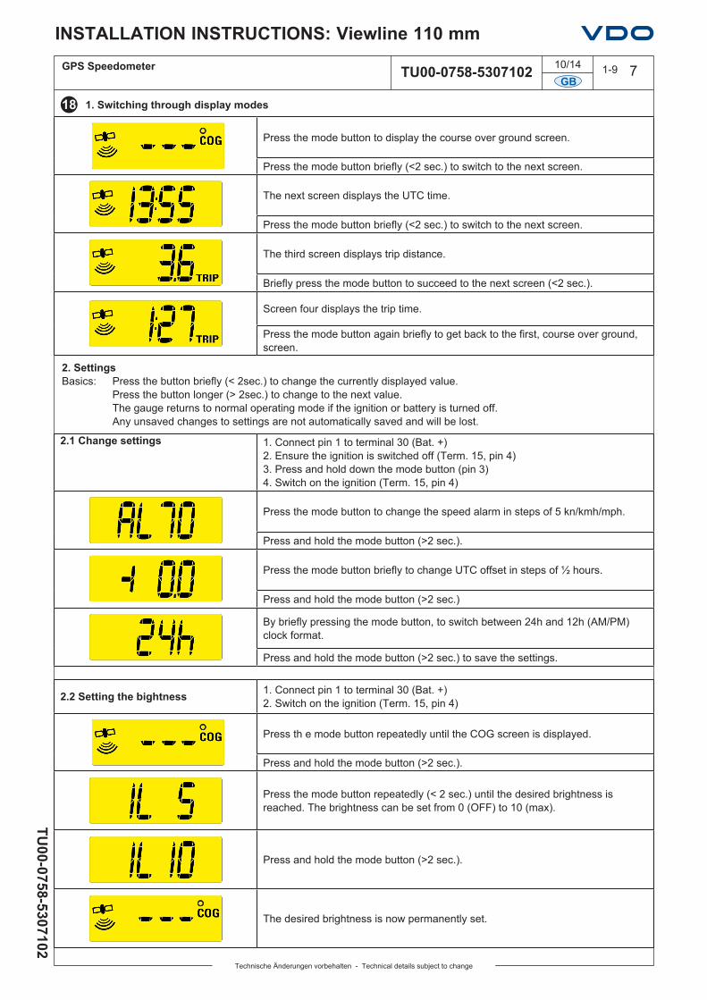
2. SettingsBasics: Press the button briefly (< 2sec.) to change the currently displayed value. Press the button longer (> 2sec.) to change to the next value. The gauge returns to normal operating mode if the ignition or battery is turned off. Any unsaved changes to settings are not automatically saved and will be lost.
2.1 Change settings 1. Connect pin 1 to terminal 30 (Bat. +) 2. Ensure the ignition is switched off (Term. 15, pin 4) 3. Press and hold down the mode button (pin 3) 4. Switch on the ignition (Term. 15, pin 4)
Press the mode button to change the speed alarm in steps of 5 kn/kmh/mph.
Press and hold the mode button (>2 sec.).
Press the mode button briefly to change UTC offset in steps of ½ hours.
Press and hold the mode button (>2 sec.)
By briefly pressing the mode button, to switch between 24h and 12h (AM/PM) clock format.
Press and hold the mode button (>2 sec.) to save the settings.
Press the mode button to display the course over ground screen.
Press the mode button briefly (<2 sec.) to switch to the next screen.
The next screen displays the UTC time.
Press the mode button briefly (<2 sec.) to switch to the next screen.
The third screen displays trip distance.
Briefly press the mode button to succeed to the next screen (<2 sec.).
Screen four displays the trip time.
Press the mode button again briefly to get back to the first, course over ground, screen.
1. Switching through display modes
2.2 Setting the bightness 1. Connect pin 1 to terminal 30 (Bat. +)2. Switch on the ignition (Term. 15, pin 4)
Press th e mode button repeatedly until the COG screen is displayed.
Press and hold the mode button (>2 sec.).
Press the mode button repeatedly (< 2 sec.) until the desired brightness is reached. The brightness can be set from 0 (OFF) to 10 (max).
Press and hold the mode button (>2 sec.).
The desired brightness is now permanently set.

10/14 1-9 8
3. In Operation
3.1 Signal strength indicator Function
Gauge searching for GPS signal (no fix).
Gauge has a fix, but data may be inaccurate.
Gauge has a fix, but signal is weak.
Gauge has a fix, signal is strong.
The strength of the signal and the time it takes to register depends on the signal quality, which can be influenced by the mounting position, weather, reflections, and large objects such as buildings or mountains.
3.3 Trip time Function
Activated (counting) At speeds above 2.6 kmh (1.6 mph/1.4 knots).
Maximum value 99 hours 59 minutes → 99:59.
Time separator blinking (1Hz) Trip time is available, trip time is being counted.
Time separator permanently on Trip time is not being counted (speed below threshold or no fix).
3.4 Trip distance Function
Activated (counting) At speeds above 2.6 kmh (1.6 mph/1.4 knots).
Maximum value 999.9 km/mi/nm → 999.9.
Trip separator blinking (1Hz) Trip distance is available, trip distance is being counted.
Trip separator permanently on Trip distance is not being counted (speed below threshold or no fix).
3.5 Warning light Function
Warning light on continuously for 1 second Battery (Pin 1) and ignition (Pin 4) are switched on.
Warning light permanently on When the programmable speed limit is exceeded. When the gauge is in programming mode.
Warning light Slow blinking (1Hz) Speed is higher than maximum indication range (35 or 70 kmh/mph/kn).
Warning light Fast blinking (2Hz) 5 times GPS signal was lost (no fix).
GB
INSTALLATION INSTRUCTIONS: Viewline 110 mm
TU00-0758-5307102
Technische Änderungen vorbehalten - Technical details subject to change
TU00-0758-5307102
GPS Speedometer
3.2 Analogue speed indication
At speeds lower than 2.6 kmh (1.6 mph/1.4 knots) the COG screen displays “---“ and the pinpoint indicators remains in the zero position.

10/14 1-9 9
20
21
19
GB
INSTALLATION INSTRUCTIONS: Viewline 110 mm
TU00-0758-5307102
Technische Änderungen vorbehalten - Technical details subject to change
TU00-0758-5307102
GPS Speedometer
Important: Clean the instrument glass and front frame with water only. Do not use chemical agents.
Accessories / Spare partsBush contacts 0.25 – 0.5 mm2 A2C59510846Bush housing, 8-pin A2C59510847Hand pliers Tyco No. 539635-1Tool for hand pliers Tyco No. 539682-2.Single contacts 0.14 – 0.22 mm2 Tyco No. 1355718-1Single contacts 0.5 – 0.75 mm2 Tyco No. 963729-1Strip 0.14 – 0.22 mm2 Tyco No. 1355717-1Strip 0.25 – 0.5 mm2 Tyco No. 928999-1
Bezel
Strip 0.5 – 0.75 mm2 Tyco No. 963715-1Bracket assembly mounting set A2C59510854 Flush mount fixing bracket A2C59510864Flush mount seal A2C53215642Push button A2C59512684Fastening nut A2C53238881Protective connector cap, 8 pin A2C53324664Protective connector cap, 14 pin A2C53324671
Black White ChromeRound A2C53210749 A2C53210760 A2C53210761Flat A2C53210745 A2C53210746 A2C53210747Triangular A2C53210763 A2C53210764 A2C53210765
3.3 Resetting the day counter 1. Connect pin 1 to terminal 30 (Bat. +) 2. Switch on the ignition (Term. 15, pin 4)
Press the mode button repeatedly until the trip distance is displayed.
Press and hold the mode button for longer (>2 sec.).
Trip is now deleted.
3.7 Resetting the trip hour 1. Connect pin 1 to terminal 30 (Bat. +) 2. Switch on the ignition (Term. 15, pin 4)
Press the mode button repeatedly until the trip time is displayed.
Press and hold the mode button for longer (>2 sec.).
Trip is now deleted.