
SECTION 9 DETAILING OF MEMBERS AND PARTICULAR RULES …web.ist.utl.pt/guilherme.f.silva/EC/EC2 -...
74
Page 157 prEN 1992-1 (Final draft) Ref. No. prEN 1992-1 (October 2001) SECTION 9 DETAILING OF MEMBERS AND PARTICULAR RULES 9.1 General (1)P The requirements for safety, serviceability and durability are satisfied by following the rules given in this section in addition to the general rules given elsewhere. (2) The detailing of members should be consistent with the design models adopted. (3) Minimum areas of reinforcement are given in order to prevent a brittle failure, wide cracks and also to resist forces arising from restrained actions. Note 1: The rules given in this section are mainly applicable to buildings and mainly valid for reinforced concrete. Note 2: All minimum and maximum values for reinforcement areas given in this section are subject to a National Annex 9.2 Beams 9.2.1 Longitudinal reinforcement 9.2.1.1 Minimum and maximum reinforcement areas (1) The minimum area of longitudinal tension reinforcement, A s,min , is given by Expression (9.1): A s,min = d b f f t yk ctm 26 , 0 but not less than 0,0013b t d (9.1) Where: b t denotes the mean width of the tension zone; for a T-beam with the flange in compression, only the width of the web is taken into account in calculating the value of b t . f ctm should be determined with respect to the relevant strength class according to Table 3.1. Alternatively, for secondary elements, where some risk of brittle failure may be accepted, A s,min may be taken as 1,2 times the area required in ULS verification. Note 1: See also 7.3 for area of longitudinal tension reinforcement to control cracking. Note 2: The minimum value for reinforcement area given in this sub-clause is subject to a National Annex. (2) Sections containing less reinforcement than that given by Expression (9.1) should be considered as unreinforced (see Section 12). (3) The cross-sectional areas of the tension reinforcement or the compression reinforcement should not normally be greater than 0,04A c outside lap locations. Note: The maximum value for reinforcement area given in this sub-clause is subject to a National Annex.
Transcript of SECTION 9 DETAILING OF MEMBERS AND PARTICULAR RULES …web.ist.utl.pt/guilherme.f.silva/EC/EC2 -...
Page 157prEN 1992-1 (Final draft)
Ref. No. prEN 1992-1 (October 2001)
SECTION 9 DETAILING OF MEMBERS AND PARTICULAR RULES
9.1 General
(1)P The requirements for safety, serviceability and durability are satisfied by following therules given in this section in addition to the general rules given elsewhere.
(2) The detailing of members should be consistent with the design models adopted.
(3) Minimum areas of reinforcement are given in order to prevent a brittle failure,wide cracks and also to resist forces arising from restrained actions.
Note 1: The rules given in this section are mainly applicable to buildings and mainly valid for reinforcedconcrete.
Note 2: All minimum and maximum values for reinforcement areas given in this section are subject to aNational Annex
9.2 Beams
9.2.1 Longitudinal reinforcement
9.2.1.1 Minimum and maximum reinforcement areas
(1) The minimum area of longitudinal tension reinforcement, As,min, is given byExpression (9.1):
As,min = dbff
tyk
ctm26,0 but not less than 0,0013btd (9.1)
Where:bt denotes the mean width of the tension zone; for a T-beam with the flange
in compression, only the width of the web is taken into account incalculating the value of bt.
fctm should be determined with respect to the relevant strength classaccording to Table 3.1.
Alternatively, for secondary elements, where some risk of brittle failure may beaccepted, As,min may be taken as 1,2 times the area required in ULS verification.
Note 1: See also 7.3 for area of longitudinal tension reinforcement to control cracking.Note 2: The minimum value for reinforcement area given in this sub-clause is subject to a National Annex.
(2) Sections containing less reinforcement than that given by Expression (9.1) shouldbe considered as unreinforced (see Section 12).
(3) The cross-sectional areas of the tension reinforcement or the compressionreinforcement should not normally be greater than 0,04Ac outside lap locations.
Note: The maximum value for reinforcement area given in this sub-clause is subject to a National Annex.
Page 158prEN 1992-1 (Final draft)
Ref. No. prEN 1992-1 (October 2001)
(4) For members prestressed with permanently unbonded tendons or with externalprestressing cables, it should be verified that the ultimate bending capacity islarger than the flexural cracking moment. A capacity of 1,15 times the crackingmoment is sufficient.
9.2.1.2 Other detailing arrangements
(1) In monolithic construction, even when simple supports have been assumed indesign, the section at supports should be designed for a bending moment arisingfrom partial fixity of at least 15% of the maximum bending moment in the span.
Note 1: The minimum value for reinforcement area given in this sub-clause is subject to a National Annex.Note 2: The minimum area of longitudinal reinforcement section defined in 9.2.1.1 (1) applies.
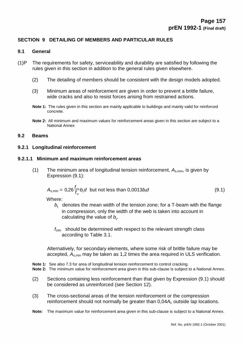
(2) At intermediate supports of continuous beams, the total area of tensionreinforcement As of a flanged cross-section should be spread over the effectivewidth of flange (see 5.3.2). Part of it may be concentrated over the web width(See Figure 9.1).
Figure 9.1: Placing of tension reinforcement in flanged cross-section.
9.2.1.3 Curtailment of longitudinal tension reinforcement
(1) Sufficient reinforcement should be provided at all sections to resist the envelopeof the acting tensile force, including the effect of inclined cracks in webs andflanges.
(2) For members with shear reinforcement the additional tensile force Ftd should becalculated according to 6.2.3 (7). For members without shear reinforcement theadditional tensile force may be estimated by shifting the moment curve a distanceal = d according to 6.2.2 (4). This "shift rule" may also be used as an alternativefor members with shear reinforcement, where:
al = z (cot θ - cot α)/2 (symbols defined in 6.2.3) (9.2)
The additional tensile force is illustrated in Figure 9.2.
bw
hf
beff1 beff2
beff
As
Page 159prEN 1992-1 (Final draft)
Ref. No. prEN 1992-1 (October 2001)
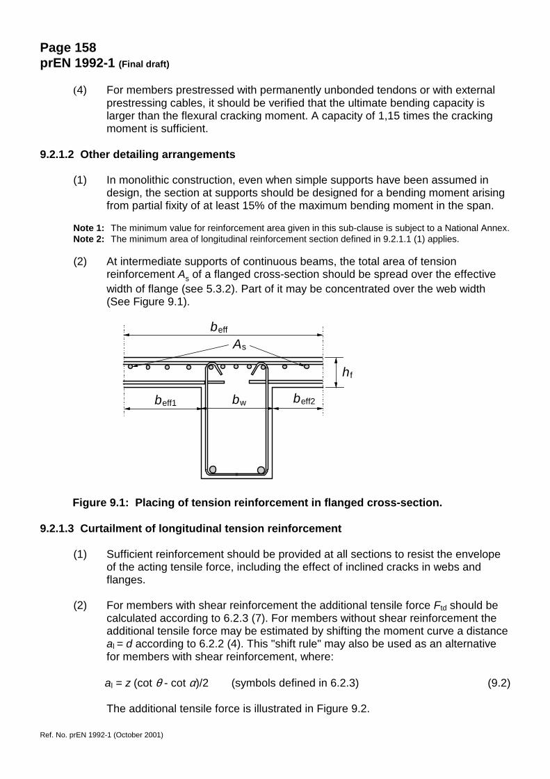
(3) The resistance of bars within their anchorage lengths may be taken into account,assuming a linear variation of force, see Figure 9.2. As a conservativesimplification this contribution may be ignored.
(4) The anchorage length of a bent-up bar which contributes to the resistance toshear should be not less than 1,3 lbd in the tension zone and 0,7 lbd in thecompression zone. It is measured from the point of intersection of the axes of thebent-up bar and the longitudinal reinforcement.
A - Envelope of MEd/z + NEd B - acting tensile force Fs C - resisting tensile force FRs
Figure 9.2: Illustration of the curtailment of longitudinal reinforcement, taking intoaccount the effect of inclined cracks and the resistance ofreinforcement within anchorage lengths
9.2.1.4 Anchorage of bottom reinforcement at an end support
(1) The area of steel provided over supports with little or no end fixity assumed indesign, should be at least 25% of the area of steel provided in the span.
Note : The minimum value for reinforcement area given in this sub-clause is subject to a National Annex.
(2) The force to be anchored may be determined according to 6.2.3 (7) (memberswith shear reinforcement) including the contribution of the axial load if any, oraccording to the shift rule:
FE = VEd . al / z + NEd (9.3)
where NEd = axial load, positive in tension; al see 9.2.1.3 (2).
al∆Ftd
al
A
B C
lbd
lbd
lbd
lbd
lbd lbd
lbd
lbd∆Ftd
Page 160prEN 1992-1 (Final draft)
Ref. No. prEN 1992-1 (October 2001)
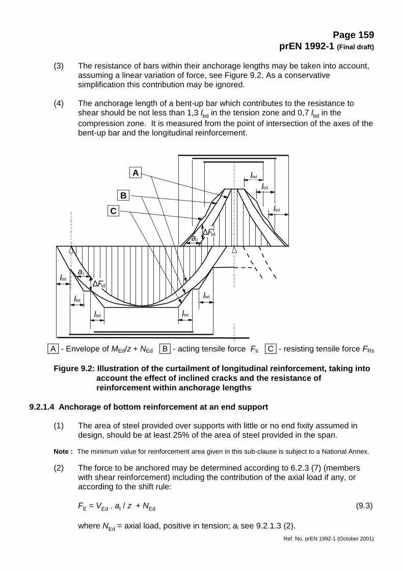
(3) The anchorage length is lbd according to 8.4.4, measured from the line of contactbetween beam and support. Transverse pressure may be taken into account fordirect support. See Figure 9.3.
a) Direct support: Beam supported bywall or column
b) Indirect support: Beam intersecting anothersupporting beam
Figure 9.3: Anchorage of bottom reinforcement at end supports
9.2.1.5 Anchorage of bottom reinforcement at intermediate supports
(1) The area of reinforcement given in 9.2.1.4 (1) applies.
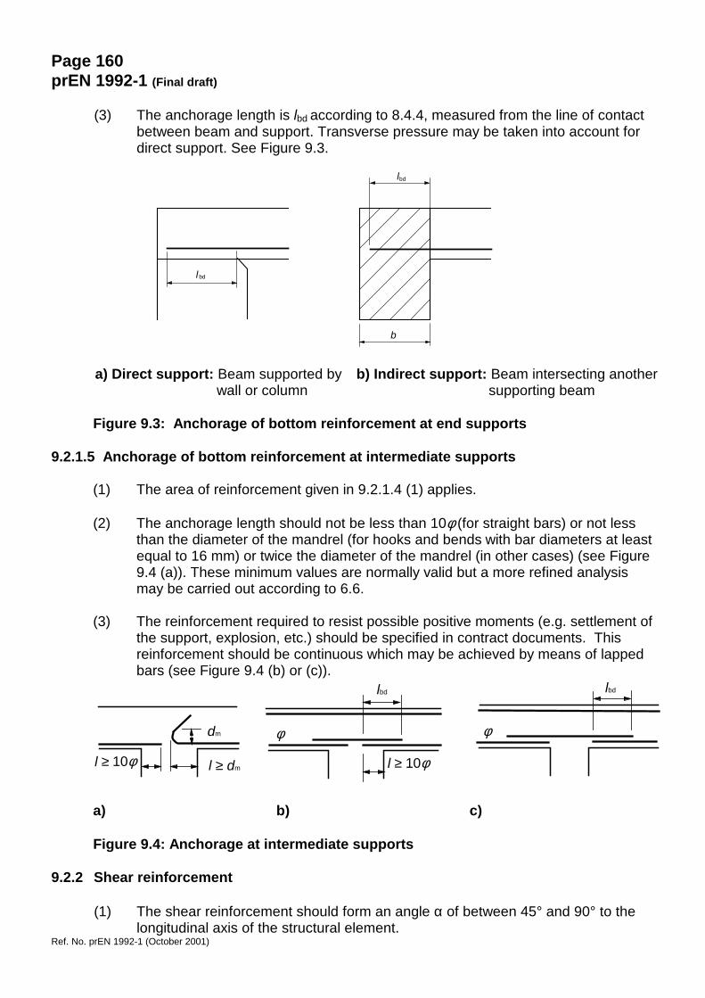
(2) The anchorage length should not be less than 10φ (for straight bars) or not lessthan the diameter of the mandrel (for hooks and bends with bar diameters at leastequal to 16 mm) or twice the diameter of the mandrel (in other cases) (see Figure9.4 (a)). These minimum values are normally valid but a more refined analysismay be carried out according to 6.6.
(3) The reinforcement required to resist possible positive moments (e.g. settlement ofthe support, explosion, etc.) should be specified in contract documents. Thisreinforcement should be continuous which may be achieved by means of lappedbars (see Figure 9.4 (b) or (c)).
a) b) c)
Figure 9.4: Anchorage at intermediate supports
9.2.2 Shear reinforcement
(1) The shear reinforcement should form an angle α of between 45° and 90° to thelongitudinal axis of the structural element.
φ
lbd
dm
l ≥ 10φ l ≥ dm
φ
lbd
l ≥ 10φ
lbd
b
lbd
Page 161prEN 1992-1 (Final draft)
Ref. No. prEN 1992-1 (October 2001)
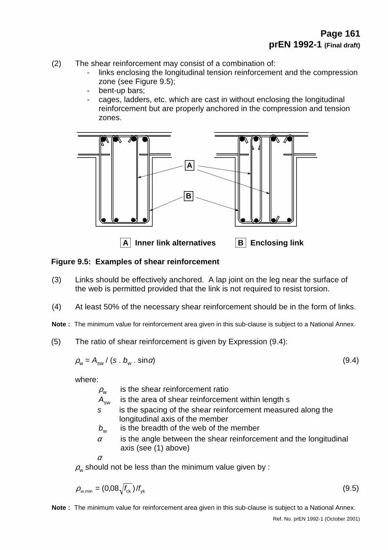
(2) The shear reinforcement may consist of a combination of:- links enclosing the longitudinal tension reinforcement and the compression
zone (see Figure 9.5);- bent-up bars;- cages, ladders, etc. which are cast in without enclosing the longitudinal
reinforcement but are properly anchored in the compression and tensionzones.
A Inner link alternatives B Enclosing link
Figure 9.5: Examples of shear reinforcement
(3) Links should be effectively anchored. A lap joint on the leg near the surface ofthe web is permitted provided that the link is not required to resist torsion.
(4) At least 50% of the necessary shear reinforcement should be in the form of links.
Note : The minimum value for reinforcement area given in this sub-clause is subject to a National Annex.
(5) The ratio of shear reinforcement is given by Expression (9.4):
ρw = Asw / (s . bw . sinα) (9.4)
where:ρw is the shear reinforcement ratioAsw is the area of shear reinforcement within length ss is the spacing of the shear reinforcement measured along the
longitudinal axis of the memberbw is the breadth of the web of the memberα is the angle between the shear reinforcement and the longitudinal
axis (see (1) above)α
ρw should not be less than the minimum value given by :
ykckw,min /)08,0( ff=ρ (9.5)
Note : The minimum value for reinforcement area given in this sub-clause is subject to a National Annex.
A
B
Page 162prEN 1992-1 (Final draft)
Ref. No. prEN 1992-1 (October 2001)
(6) The maximum longitudinal spacing smax between shear assemblies is:
smax = 0,75d (1 + cot α ) (9.6)
where α is the inclination of the shear reinforcement to the longitudinal axis ofthe beam.
Note : The maximum value for longitudinal spacing given in this sub-clause is subject to a NationalAnnex.
(7) The maximum longitudinal spacing of bent-up bars is defined by:
smax = 0,6 d (1 + cot α) (9.7)
Note : The maximum value for longitudinal spacing given in this sub-clause is subject to a NationalAnnex.
(8) The transverse spacing of the legs in a series of shear links should not exceed:
smax = 0,75d ≤ 600 mm (9.8)
Note : The maximum value for transverse spacing given in this sub-clause is subject to a National Annex.
(9) Any compression longitudinal reinforcement (diameter φ) which is included in theresistance calculation should be held by transverse reinforcement with spacingnot greater than 15φ.
9.2.3 Torsion reinforcement
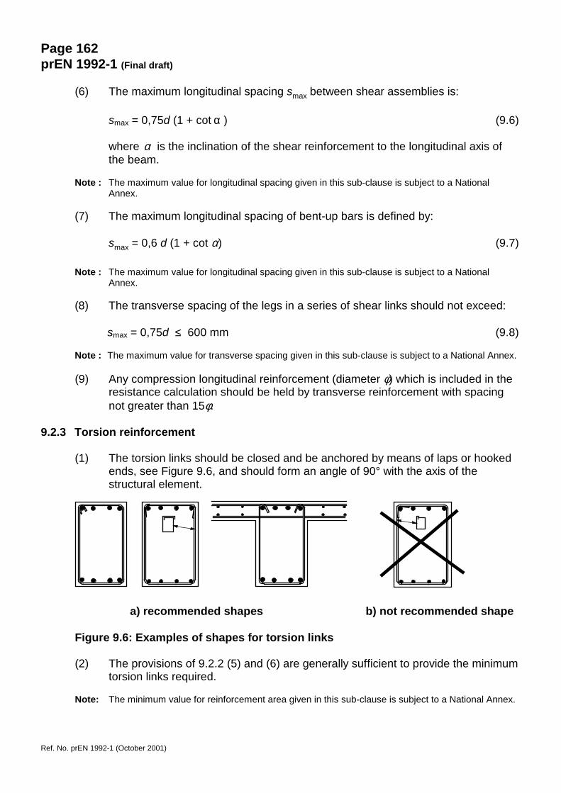
(1) The torsion links should be closed and be anchored by means of laps or hookedends, see Figure 9.6, and should form an angle of 90° with the axis of thestructural element.
a) recommended shapes b) not recommended shape
Figure 9.6: Examples of shapes for torsion links
(2) The provisions of 9.2.2 (5) and (6) are generally sufficient to provide the minimumtorsion links required.
Note: The minimum value for reinforcement area given in this sub-clause is subject to a National Annex.

Page 163prEN 1992-1 (Final draft)
Ref. No. prEN 1992-1 (October 2001)
(3) The longitudinal spacing of the torsion links should not exceed u / 8 (see 6.3.2,Figure 6.11, for the notation), or the requirement in 9.2.2 (6) or the lesserdimension of the beam cross-section.
(4) The longitudinal bars should be so arranged that there is at least one bar at eachcorner, the others being distributed uniformly around the inner periphery of thelinks, with a spacing not greater than 350 mm.
9.2.4 Surface reinforcement
(1) It may be necessary to provide surface reinforcement either to control cracking orto ensure adequate resistance to spalling of the cover.
(2) Surface reinforcement to resist spalling should be used where:- bars with diameter greater than 32 mm or- bundled bars with equivalent diameter greater than 32 mm (see 8.8)
The surface reinforcement should consist of wire mesh or small diameter bars,and be placed outside the links as indicated in Figure 9.7.
x is the depth of the neutral axis at ULS
Figure 9.7: Example of surface reinforcement
(3) The area of surface reinforcement As,surf should be not less than 0,01 Act,ext in thetwo directions parallel and orthogonal to the tension reinforcement in the beam.
Act,ext is the area of the tensile concrete external to the links (see Figure 9.7).
Note: The minimum value for reinforcement area given in this sub-clause is subject to a National Annex.
(4) Where the cover to reinforcement is greater than 70 mm, for enhanced durabilitysimilar surface reinforcement should be used, with an area of 0,005 Act,ext in eachdirection.
(5) The minimum cover needed for the surface reinforcement is given in 4.4.1.2.
As,surf ≥≥≥≥ 0,01 Act,ext
st ≤ 150 mm
A ct,ext
As,surf
sl ≤ 150 mm
x
(d - x) ≤ 600 mm
Page 164prEN 1992-1 (Final draft)
Ref. No. prEN 1992-1 (October 2001)
(6) The longitudinal bars of the surface reinforcement may be taken into account aslongitudinal bending reinforcement and the transverse bars as shearreinforcement provided that they meet the requirements for the arrangement andanchorage of these types of reinforcement.
9.2.5 Indirect supports
(1) Where a beam is supported by a beam instead of a wall or column, reinforcementshould be provided and designed to resist the mutual reaction. Thisreinforcement is in addition to that required for other reasons. This rule alsoapplies to a slab not supported at the top of a beam.
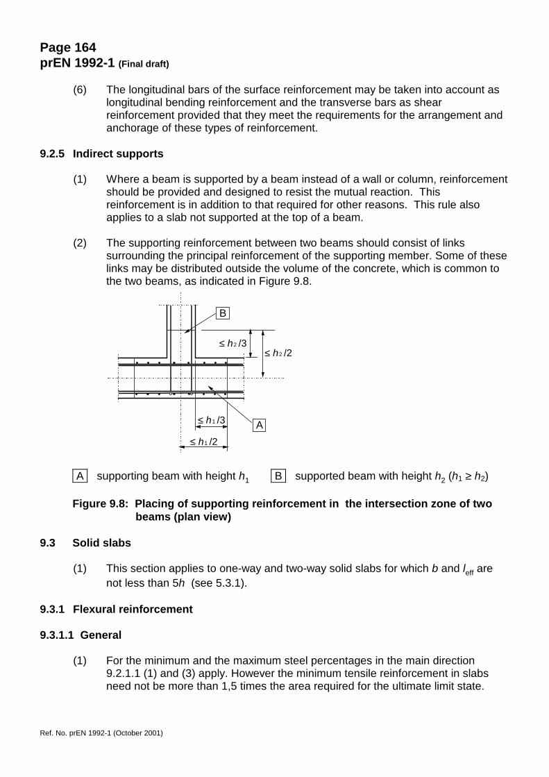
(2) The supporting reinforcement between two beams should consist of linkssurrounding the principal reinforcement of the supporting member. Some of theselinks may be distributed outside the volume of the concrete, which is common tothe two beams, as indicated in Figure 9.8.
A supporting beam with height h1 B supported beam with height h2 (h1 ≥ h2)
Figure 9.8: Placing of supporting reinforcement in the intersection zone of twobeams (plan view)
9.3 Solid slabs
(1) This section applies to one-way and two-way solid slabs for which b and leff arenot less than 5h (see 5.3.1).
9.3.1 Flexural reinforcement
9.3.1.1 General
(1) For the minimum and the maximum steel percentages in the main direction9.2.1.1 (1) and (3) apply. However the minimum tensile reinforcement in slabsneed not be more than 1,5 times the area required for the ultimate limit state.
≤ h /31
≤ h /21
B
A
≤ h /32
≤ h /22
Page 165prEN 1992-1 (Final draft)
Ref. No. prEN 1992-1 (October 2001)
(2) Generally secondary transverse reinforcement of not less than 20% of theprincipal reinforcement should be provided in one way slabs. In areas nearsupports transverse reinforcement to principal top bars is not necessary wherethere is no transverse bending moment.
(3) The rules for the maximum spacing of bars are as follows:- for the principal reinforcement, 3h ≤ 400 mm, where h is the total depth of
the slab;- for the secondary reinforcement, 3,5h ≤ 450 mm .
(4) In areas with concentrated loads or areas of maximum moment those provisionsbecome respectively:- for the principal reinforcement, 2h ≤ 250 mm- for the secondary reinforcement, 3h ≤ 400 mm .
(5) The rules given in 9.2.1.3 (1) to (3), 9.2.1.4 (1) to (3) and 9.2.1.5 (1) to (2) alsoapply but with al = d.
9.3.1.2 Reinforcement in slabs near supports
(1) In simply supported slabs, half the calculated span reinforcement should continueup to the support and be anchored therein in accordance with 8.4.4.
Note: Curtailing and anchoring reinforcement may be carried out according to 9.2.1.3, 9.2.1.4 and9.2.1.5.
(2) Where partial fixity occurs along an edge of a slab, but is not taken into account inthe analysis, the top reinforcement should be capable of resisting at least 25% ofthe maximum moment in the adjacent span. This reinforcement should at least0,2 times the length of the adjacent span, measured from the face of the support.It should be continuous across internal supports and anchored at end supports.At an end support the moment to be resisted may be reduced to 15% of themaximum moment in the adjacent span.
9.3.1.3 Corner reinforcement
(1) If the detailing arrangements at a support are such that lifting of the slab at acorner is restrained, suitable reinforcement should be provided.
9.3.1.4 Reinforcement at the free edges
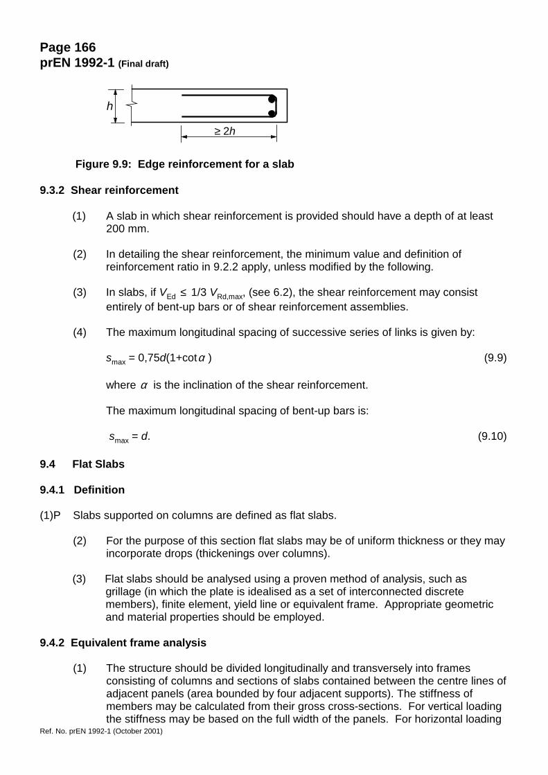
(1) Along a free (unsupported) edge, a slab should normally contain longitudinal andtransverse reinforcement, generally arranged as shown in Figure 9.9.
(2) The normal reinforcement provided for a slab may act as edge reinforcement.
Page 166prEN 1992-1 (Final draft)
Ref. No. prEN 1992-1 (October 2001)
Figure 9.9: Edge reinforcement for a slab
9.3.2 Shear reinforcement
(1) A slab in which shear reinforcement is provided should have a depth of at least200 mm.
(2) In detailing the shear reinforcement, the minimum value and definition ofreinforcement ratio in 9.2.2 apply, unless modified by the following.
(3) In slabs, if VEd ≤ 1/3 VRd,max, (see 6.2), the shear reinforcement may consistentirely of bent-up bars or of shear reinforcement assemblies.
(4) The maximum longitudinal spacing of successive series of links is given by:
smax = 0,75d(1+cotα ) (9.9)
where α is the inclination of the shear reinforcement.
The maximum longitudinal spacing of bent-up bars is:
smax = d. (9.10)
9.4 Flat Slabs
9.4.1 Definition
(1)P Slabs supported on columns are defined as flat slabs.
(2) For the purpose of this section flat slabs may be of uniform thickness or they mayincorporate drops (thickenings over columns).
(3) Flat slabs should be analysed using a proven method of analysis, such asgrillage (in which the plate is idealised as a set of interconnected discretemembers), finite element, yield line or equivalent frame. Appropriate geometricand material properties should be employed.
9.4.2 Equivalent frame analysis
(1) The structure should be divided longitudinally and transversely into framesconsisting of columns and sections of slabs contained between the centre lines ofadjacent panels (area bounded by four adjacent supports). The stiffness ofmembers may be calculated from their gross cross-sections. For vertical loadingthe stiffness may be based on the full width of the panels. For horizontal loading
≥ 2h
h
Page 167prEN 1992-1 (Final draft)
Ref. No. prEN 1992-1 (October 2001)
40% of this value should be used to reflect the increased flexibility of thecolumn/slab joints in flat slab structures compared to that of column/beam joints.Total load on the panel should be used for the analysis in each direction.
(2) The total bending moments obtained from analysis should be distributed acrossthe width of the slab. In elastic analysis negative moments tend to concentratetowards the centre lines of the columns.
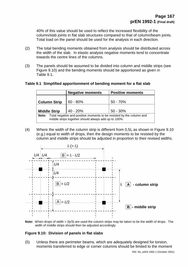
(3) The panels should be assumed to be divided into column and middle strips (seeFigure 9.10) and the bending moments should be apportioned as given inTable 9.1.
Table 9.1 Simplified apportionment of bending moment for a flat slab
Negative moments Positive moments
Column Strip 60 - 80% 50 - 70%
Middle Strip 40 - 20% 50 - 30%Note: Total negative and positive moments to be resisted by the column and
middle strips together should always add up to 100%.
(4) Where the width of the column strip is different from 0,5lx as shown in Figure 9.10(e.g.) equal to width of drops, then the design moments to be resisted by thecolumn and middle strips should be adjusted in proportion to their revised widths.
A - column strip
B - middle strip
Note: When drops of width > (ly/3) are used the column strips may be taken to be the width of drops. Thewidth of middle strips should then be adjusted accordingly.
Figure 9.10: Division of panels in flat slabs
(5) Unless there are perimeter beams, which are adequately designed for torsion,moments transferred to edge or corner columns should be limited to the moment
lx (> ly)
ly
ly/4 ly/4
ly/4
ly/4
= lx - ly/2
= ly/2
= ly/2 A
B
B
Page 168prEN 1992-1 (Final draft)
Ref. No. prEN 1992-1 (October 2001)
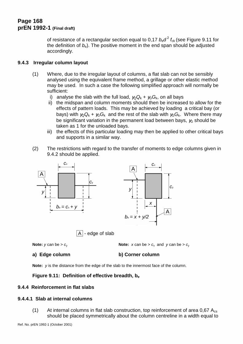
of resistance of a rectangular section equal to 0,17 bed 2 fck (see Figure 9.11 forthe definition of be). The positive moment in the end span should be adjustedaccordingly.
9.4.3 Irregular column layout
(1) Where, due to the irregular layout of columns, a flat slab can not be sensiblyanalysed using the equivalent frame method, a grillage or other elastic methodmay be used. In such a case the following simplified approach will normally besufficient: i) analyse the slab with the full load, γQQk + γGGk, on all bays ii) the midspan and column moments should then be increased to allow for the
effects of pattern loads. This may be achieved by loading a critical bay (orbays) with γQQk + γGGk and the rest of the slab with γGGk. Where there maybe significant variation in the permanent load between bays, γG should betaken as 1 for the unloaded bays.
iii) the effects of this particular loading may then be applied to other critical baysand supports in a similar way.
(2) The restrictions with regard to the transfer of moments to edge columns given in9.4.2 should be applied.
A - edge of slab
Note: y can be > cy Note: x can be > cx and y can be > cy
a) Edge column b) Corner column
Note: y is the distance from the edge of the slab to the innermost face of the column.
Figure 9.11: Definition of effective breadth, be
9.4.4 Reinforcement in flat slabs
9.4.4.1 Slab at internal columns
(1) At internal columns in flat slab construction, top reinforcement of area 0,67 Acsshould be placed symmetrically about the column centreline in a width equal to
cx
cy
y
be = cx + y
A
cx
cyy
A
be = x + y/2
x
A
Page 169prEN 1992-1 (Final draft)
Ref. No. prEN 1992-1 (October 2001)
half that of the column strip. Acs represents the area of reinforcement required toresist the negative moment in the column strip (see Figure 9.10).
(2) Bottom reinforcement (≥ 2 bars) in each orthogonal direction should be providedat internal columns and this reinforcement should pass through the column.
9.4.4.2 Slab at edge columns
(1) Reinforcement perpendicular to a free edge required to transmit bendingmoments from the slab to an edge column should be placed within the effectivebreadth be shown in Figure 9.11.
9.4.4.3 Punching shear reinforcement
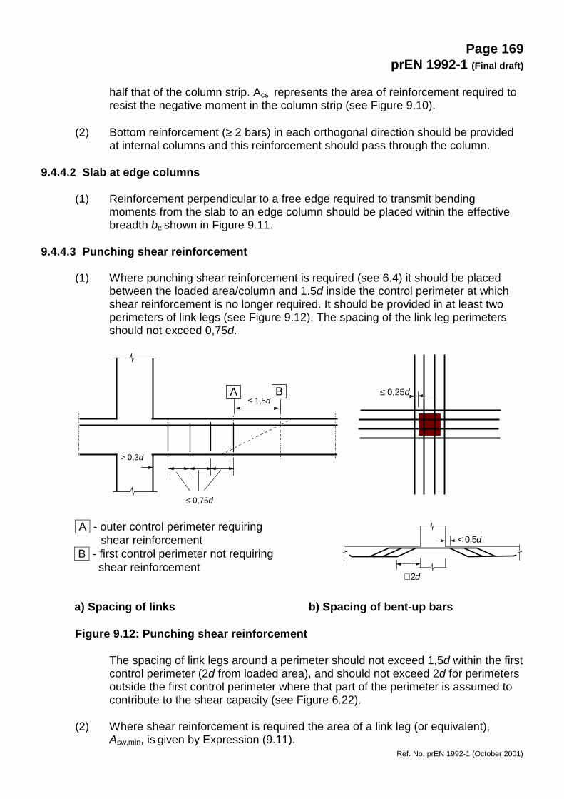
(1) Where punching shear reinforcement is required (see 6.4) it should be placedbetween the loaded area/column and 1.5d inside the control perimeter at whichshear reinforcement is no longer required. It should be provided in at least twoperimeters of link legs (see Figure 9.12). The spacing of the link leg perimetersshould not exceed 0,75d.
A - outer control perimeter requiringshear reinforcement
B - first control perimeter not requiring shear reinforcement
a) Spacing of links b) Spacing of bent-up bars
Figure 9.12: Punching shear reinforcement
The spacing of link legs around a perimeter should not exceed 1,5d within the firstcontrol perimeter (2d from loaded area), and should not exceed 2d for perimetersoutside the first control perimeter where that part of the perimeter is assumed tocontribute to the shear capacity (see Figure 6.22).
(2) Where shear reinforcement is required the area of a link leg (or equivalent),Asw,min, is given by Expression (9.11).
< 0,5d
≅ 2d
≤ 0,25d
≤ 0,75d
> 0,3d
A B ≤ 1,5d
Page 170prEN 1992-1 (Final draft)
Ref. No. prEN 1992-1 (October 2001)
Asw,min ⋅ (1,5⋅sinα + cosα)/(sr⋅ st) ≥ (0,8 ⋅√(fck·fck0))/fyk (9.11)
where :α angle between the shear reinforcement and the main steel (i.e. for
vertical links α = 90° and sin α = 1)sr spacing of shear links in the radial directionst spacing of shear links in the tangential directionfck0 reference strength to be taken as 1 MPa
(3) Bent-up bars passing through the loaded area or at a distance not exceeding0,25d from this area may be used as shear reinforcement.
(4) The distance between the face of a support, or the circumference of a loadedarea, and the nearest shear reinforcement taken into account in the designshould not exceed d/2. This distance should be taken at the level of the tensilereinforcement; if only a single line of bent-up bars is provided, their slope may bereduced to 30°.
9.5 Columns
(1) This clause deals with columns for which the larger dimension h is not greaterthan 4 times the smaller dimension b.
9.5.1 Longitudinal reinforcement
(1) Bars should have a diameter of not less than 8 mm.
Note: The minimum diameter given in this sub-clause is subject to a National Annex.
(2) The minimum amount of total longitudinal reinforcement As,min should be derivedfrom the following condition:
yd
Eds,min
10,0f
NA = or 0,002 Ac whichever is the greater (9.12)
where:fyd is the design yield strength of the reinforcementNEd is the design axial compression force
Note: The minimum reinforcement area given in this sub-clause is subject to a National Annex.
(3) The area of reinforcement should not exceed 0,04 Ac outside lap locations unlessit can be shown that the integrity of concrete is not affected, and that the fullstrength is achieved at ULS. This limit should be increased to 0,08 Ac at laps.
Note: The maximum reinforcement area given in this sub-clause is subject to a National Annex.
(4) For columns having a polygonal cross-section, at least one bar should be placedat each corner. The number of longitudinal bars in a circular column should not beless than four.
Page 171prEN 1992-1 (Final draft)
Ref. No. prEN 1992-1 (October 2001)
9.5.2 Transverse reinforcement
(1) The diameter of the transverse reinforcement (links, loops or helical spiralreinforcement) should not be less than 6 mm or one quarter of the maximumdiameter of the longitudinal bars, whichever is the greater. The diameter of thewires of welded mesh fabric for transverse reinforcement should not be less than5 mm.
(2) The transverse reinforcement should be anchored adequately.
(3) The spacing of the transverse reinforcement along the column should not exceedthe lesser of the following three distances:
- 20 times the minimum diameter of the longitudinal bars- the lesser dimension of the column- 400 mm
Note : The maximum spacing given in this sub-clause is subject to a National Annex.
(4) The maximum spacing required in (3) should be reduced by a factor 0,6:
(i) in sections within a distance equal to the larger dimension of the columncross-section above or below a beam or slab;
(ii) near lapped joints, if the maximum diameter of the longitudinal bars isgreater than 14 mm. A minimum of 3 bars evenly placed in the lap lengthis required.
(5) Where the direction of the longitudinal bars changes, (e.g. at changes in columnsize), the spacing of transverse reinforcement should be calculated, takingaccount of the lateral forces involved. These effects may be ignored if the changeof direction is less than or equal to 1 in 12.
(6) Every longitudinal bar or bundled bars placed in a corner should be held bytransverse reinforcement. No bar within a compression zone should be furtherthan 150 mm from a restrained bar.
9.6 Walls
9.6.1 General
(1) This clause refers to reinforced concrete walls with a length to thickness ratio of 4or more and in which the reinforcement is taken into account in the strengthanalysis. The amount and proper detailing of reinforcement may be derived froma strut-and-tie model (see 6.5). For walls subjected predominantly to out-of-planebending the rules for slabs apply (see 9.3).
9.6.2 Vertical reinforcement
(1) The area of the vertical reinforcement should be between 0,002 Ac and 0,04 Acoutside lap locations unless it can be shown that the concrete integrity is not
Page 172prEN 1992-1 (Final draft)
Ref. No. prEN 1992-1 (October 2001)
affected and that the full strength is achieved at ULS. The limits may be doubledat laps.
Note: The minimum value for reinforcement area given in this sub-clause is subject to a National Annex.
(2) Where the minimum area of reinforcement controls in design, half of this areashould be located at each face.
(3) The distance between two adjacent vertical bars shall not exceed 3 times the wallthickness or 400 mm whichever is the lesser.
9.6.3 Horizontal reinforcement
(1) Horizontal reinforcement running parallel to the faces of the wall (and to the freeedges) should be provided at each surface. It should not be less than either 25%of the vertical reinforcement or 0,001 Ac.
Note: The minimum value for reinforcement area given in this sub-clause is subject to a National Annex.
(2) The spacing between two adjacent horizontal bars should not be greater than400 mm.
9.6.4 Transverse reinforcement
(1) In any part of a wall where the total area of the vertical reinforcement in the twofaces exceeds 0,02 Ac, transverse reinforcement in the form of links should beprovided in accordance with the requirements for columns (see 9.4.2).
(2) Except for welded wire mesh and bars of diameter φ ≤ 16 mm used with concretecover larger than 2φ , where main reinforcements are placed at the nearest of wallfaces, transverse reinforcement should also be provided in the form of links at anumber of 4 per m2 of wall area.
9.7 Deep beams
(1) Deep beams (for definition see 5.3.1 (2), (3)) should normally be provided with anorthogonal reinforcement mesh near each face, with a minimum of 0,075% butnot less than as=150 mm²/min in each face and each direction.
Note: The minimum reinforcement area given in this sub-clause is subject to a National Annex.
(2) The distance between two adjacent bars of the mesh should not exceed thelesser of twice the wall thickness or 300 mm.
(3) Reinforcement, corresponding to the ties considered in the design model, shouldbe fully anchored for equilibrium in the node, see 6.5.4, by bending the bars, byusing U-hoops or by anchorage devices, unless a sufficient length is availablebetween the node and the end of the beam permitting an anchorage length of lbd.

Page 173prEN 1992-1 (Final draft)
Ref. No. prEN 1992-1 (October 2001)
(4) Deep beams should be provided with distributed reinforcement close to eachface. This may consist of an orthogonal mesh for each face with at least 0,001 Acin each direction.
Note: The minimum value for reinforcement area given in this sub-clause is subject to a National Annex.
9.8 Foundations
9.8.1 Pile caps
(1) The distance from the outer edge of the pile to the edge of the pile cap should besuch that the tie forces in the pile cap can be properly anchored. The expecteddeviation of the pile on site should be taken into account.
(2) Reinforcement in a pile cap should be calculated either by using strut-and-tie orflexural methods as appropriate.
(3) The main tensile reinforcement to resist the action effects should be concentratedin the stress zones between the tops of the piles. If the area of this reinforcementis at least equal to the minimum reinforcement, evenly distributed bars along thebottom surface of the member may be omitted. Also the sides and the top surfaceof the member may be unreinforced if there is no risk of tension developing inthese parts of the member.
(4) Welded transverse bars may be used for the anchorage of the tensionreinforcement. In this case the transverse bar may be considered to be part of thetransverse reinforcement in the anchorage zone of the reinforcement barconsidered.
(5) The compression caused by the support reaction from the pile may be assumedto spread at 45 degree angles from the edge of the pile (see Figure 9.13). Thiscompression may be taken into account when calculating the anchorage length.
A - compressed area
Figure 9.13: Compressed area increasing the anchorage capacity
9.8.2 Column and wall footings
(1) The main reinforcement should be anchored in accordance with the requirementsof 8.4 and 8.5. In footings the design model shown in 9.8.2.1 may be used.
45
50 mm
A
Page 174prEN 1992-1 (Final draft)
Ref. No. prEN 1992-1 (October 2001)
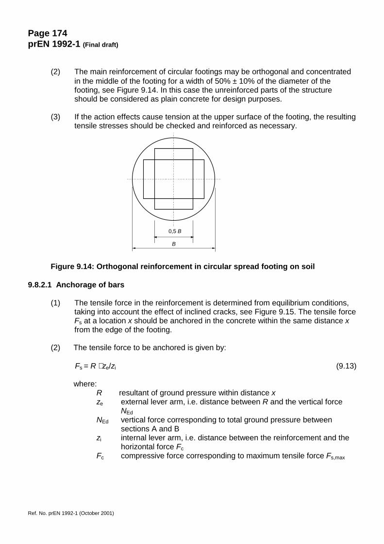
(2) The main reinforcement of circular footings may be orthogonal and concentratedin the middle of the footing for a width of 50% ± 10% of the diameter of thefooting, see Figure 9.14. In this case the unreinforced parts of the structureshould be considered as plain concrete for design purposes.
(3) If the action effects cause tension at the upper surface of the footing, the resultingtensile stresses should be checked and reinforced as necessary.
Figure 9.14: Orthogonal reinforcement in circular spread footing on soil
9.8.2.1 Anchorage of bars
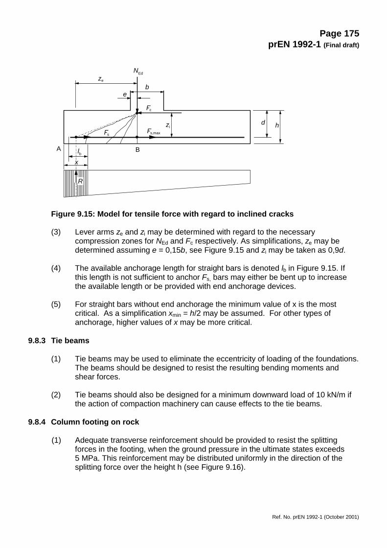
(1) The tensile force in the reinforcement is determined from equilibrium conditions,taking into account the effect of inclined cracks, see Figure 9.15. The tensile forceFs at a location x should be anchored in the concrete within the same distance xfrom the edge of the footing.
(2) The tensile force to be anchored is given by:
Fs = R ⋅ ze/zi (9.13)
where:R resultant of ground pressure within distance xze external lever arm, i.e. distance between R and the vertical force
NEdNEd vertical force corresponding to total ground pressure between
sections A and Bzi internal lever arm, i.e. distance between the reinforcement and the
horizontal force FcFc compressive force corresponding to maximum tensile force Fs,max
0,5 B
B
Page 175prEN 1992-1 (Final draft)
Ref. No. prEN 1992-1 (October 2001)
Figure 9.15: Model for tensile force with regard to inclined cracks
(3) Lever arms ze and zi may be determined with regard to the necessarycompression zones for NEd and Fc respectively. As simplifications, ze may bedetermined assuming e = 0,15b, see Figure 9.15 and zi may be taken as 0,9d.
(4) The available anchorage length for straight bars is denoted lb in Figure 9.15. Ifthis length is not sufficient to anchor Fs, bars may either be bent up to increasethe available length or be provided with end anchorage devices.
(5) For straight bars without end anchorage the minimum value of x is the mostcritical. As a simplification xmin = h/2 may be assumed. For other types ofanchorage, higher values of x may be more critical.
9.8.3 Tie beams
(1) Tie beams may be used to eliminate the eccentricity of loading of the foundations.The beams should be designed to resist the resulting bending moments andshear forces.
(2) Tie beams should also be designed for a minimum downward load of 10 kN/m ifthe action of compaction machinery can cause effects to the tie beams.
9.8.4 Column footing on rock
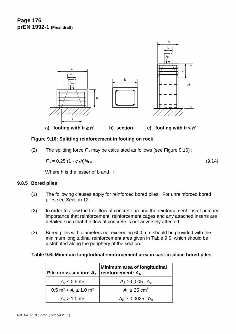
(1) Adequate transverse reinforcement should be provided to resist the splittingforces in the footing, when the ground pressure in the ultimate states exceeds5 MPa. This reinforcement may be distributed uniformly in the direction of thesplitting force over the height h (see Figure 9.16).
A Blbx
R
FsFs,max
Fc
zi
e
ze
NEd
b
d h
Page 176prEN 1992-1 (Final draft)
Ref. No. prEN 1992-1 (October 2001)
a) footing with h ≥≥≥≥ H b) section c) footing with h < H
Figure 9.16: Splitting reinforcement in footing on rock
(2) The splitting force FS may be calculated as follows (see Figure 9.16) :
FS = 0,25 (1 - c /h)NEd (9.14)
Where h is the lesser of b and H
9.8.5 Bored piles
(1) The following clauses apply for reinforced bored piles. For unreinforced boredpiles see Section 12.
(2) In order to allow the free flow of concrete around the reinforcement it is of primaryimportance that reinforcement, reinforcement cages and any attached inserts aredetailed such that the flow of concrete is not adversely affected.
(3) Bored piles with diameters not exceeding 600 mm should be provided with theminimum longitudinal reinforcement area given in Table 9.6, which should bedistributed along the periphery of the section.
Table 9.6: Minimum longitudinal reinforcement area in cast-in-place bored piles
Pile cross-section: Ac
Minimum area of longitudinalreinforcement: AS
Ac ≤ 0,5 m² AS ≥ 0,005 ⋅ Ac
0,5 m² < Ac ≤ 1,0 m² AS ≥ 25 cm2
Ac > 1,0 m² AS ≥ 0,0025 ⋅ Ac
H
h
H
H
bc
bc
bNEd
NEd
Page 177prEN 1992-1 (Final draft)
Ref. No. prEN 1992-1 (October 2001)
(4) The minimum diameter for the longitudinal bars should not be less than 16 mm.Piles should have at least 6 longitudinal bars. The clear distance between barsshould not exceed 200 mm measured along the periphery of the pile.
Note: These detailing limitations are subject to a National Annex.
(5) For the detailing of longitudinal and transverse reinforcement in bored piles, seeEN 1536.
9.9 Regions with discontinuity in geometry or action
P(1) D-Regions shall be designed with strut-and-tie models according to section 6.5 anddetailed according to the rules given in Section 8. The following simple rules are deemedto satisfy this requirement.
P(2) The reinforcement, corresponding to the ties, shall be fully anchored by an anchorage oflbd according to 8.4.
9.9.1 Frame corners
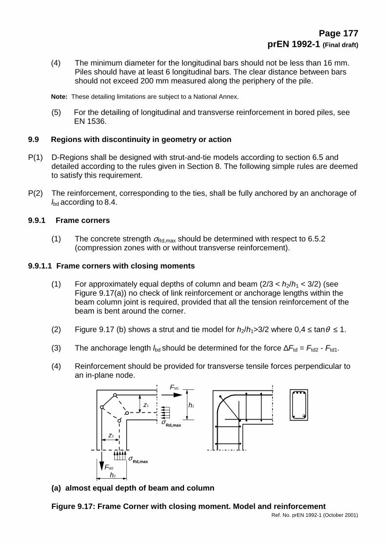
(1) The concrete strength σRd,max should be determined with respect to 6.5.2(compression zones with or without transverse reinforcement).
9.9.1.1 Frame corners with closing moments
(1) For approximately equal depths of column and beam (2/3 < h2/h1 < 3/2) (seeFigure 9.17(a)) no check of link reinforcement or anchorage lengths within thebeam column joint is required, provided that all the tension reinforcement of thebeam is bent around the corner.
(2) Figure 9.17 (b) shows a strut and tie model for h2/h1>3/2 where 0,4 ≤ tanθ ≤ 1.
(3) The anchorage length lbd should be determined for the force ∆Ftd = Ftd2 - Ftd1.
(4) Reinforcement should be provided for transverse tensile forces perpendicular toan in-plane node.
(a) almost equal depth of beam and column
Figure 9.17: Frame Corner with closing moment. Model and reinforcement
z1
z2
Ftd1
h2
σ Rd,max
h1
σ Rd,maxFtd2
Page 178prEN 1992-1 (Final draft)
Ref. No. prEN 1992-1 (October 2001)
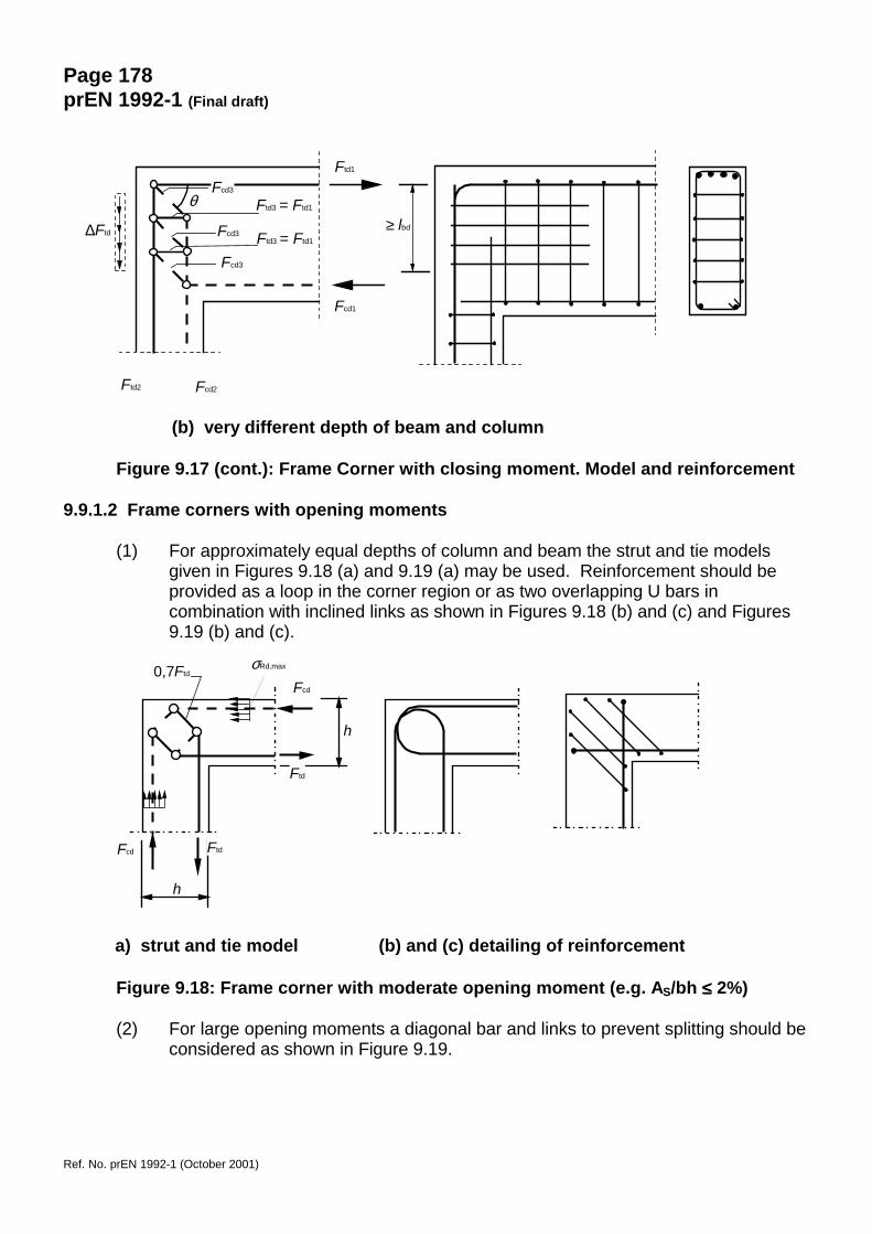
(b) very different depth of beam and column
Figure 9.17 (cont.): Frame Corner with closing moment. Model and reinforcement
9.9.1.2 Frame corners with opening moments
(1) For approximately equal depths of column and beam the strut and tie modelsgiven in Figures 9.18 (a) and 9.19 (a) may be used. Reinforcement should beprovided as a loop in the corner region or as two overlapping U bars incombination with inclined links as shown in Figures 9.18 (b) and (c) and Figures9.19 (b) and (c).
a) strut and tie model (b) and (c) detailing of reinforcement
Figure 9.18: Frame corner with moderate opening moment (e.g. AS/bh ≤≤≤≤ 2%)
(2) For large opening moments a diagonal bar and links to prevent splitting should beconsidered as shown in Figure 9.19.
∆Ftd
θ
Ftd2
Ftd1
Fcd1
Fcd2
Ftd3 = Ftd1
Ftd3 = Ftd1
Fcd3
Fcd3
Fcd3
≥ lbd
h
h
σRd,max 0,7Ftd
Fcd
Ftd
Fcd Ftd
Page 179prEN 1992-1 (Final draft)
Ref. No. prEN 1992-1 (October 2001)
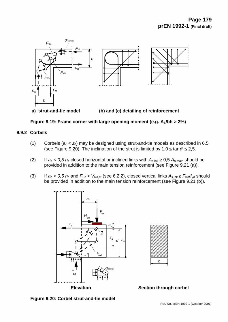
a) strut-and-tie model (b) and (c) detailing of reinforcement
Figure 9.19: Frame corner with large opening moment (e.g. AS/bh > 2%)
9.9.2 Corbels
(1) Corbels (ac < z0) may be designed using strut-and-tie models as described in 6.5(see Figure 9.20). The inclination of the strut is limited by 1,0 ≤ tanθ ≤ 2,5.
(2) If ac < 0,5 hc closed horizontal or inclined links with As,lnk ≥ 0,5 As,main should beprovided in addition to the main tension reinforcement (see Figure 9.21 (a)).
(3) If ac > 0,5 hc and FEd > VRd,ct (see 6.2.2), closed vertical links As,lnk ≥ Fwd/fyd shouldbe provided in addition to the main tension reinforcement (see Figure 9.21 (b)).
Elevation Section through corbel
Figure 9.20: Corbel strut-and-tie model
h
h
σRd,max Ftd2
Fcd
Ftd
Ftd3
Ftd1
FtdFcd
FEdHEd
FEd
Ftd
ac
σRd,max
1
2θ
Fwd
dz0
aH
hc
b
Page 180prEN 1992-1 (Final draft)
Ref. No. prEN 1992-1 (October 2001)
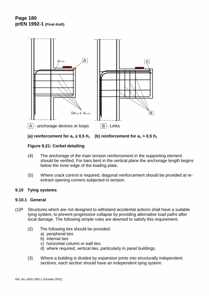
A - anchorage devices or loops B - Links
(a) reinforcement for ac ≤≤≤≤ 0,5 hc (b) reinforcement for ac > 0,5 hc
Figure 9.21: Corbel detailing
(4) The anchorage of the main tension reinforcement in the supporting elementshould be verified. For bars bent in the vertical plane the anchorage length beginsbelow the inner edge of the loading plate.
(5) Where crack control is required, diagonal reinforcement should be provided at re-entrant opening corners subjected to tension.
9.10 Tying systems
9.10.1 General
(1)P Structures which are not designed to withstand accidental actions shall have a suitabletying system, to prevent progressive collapse by providing alternative load paths afterlocal damage. The following simple rules are deemed to satisfy this requirement.
(2) The following ties should be provided:a) peripheral tiesb) internal tiesc) horizontal column or wall tiesd) where required, vertical ties, particularly in panel buildings.
(3) Where a building is divided by expansion joints into structurally independentsections, each section should have an independent tying system.
A As,main
ΣAs,lnk ≥ As,main
A
B
Page 181prEN 1992-1 (Final draft)
Ref. No. prEN 1992-1 (October 2001)
(4) In the design of the ties the reinforcement may be assumed to be acting at itscharacteristic strength and capable of carrying tensile forces defined in thefollowing clauses.
(5) Reinforcement provided for other purposes in columns, walls, beams and floorsmay be regarded as providing part of or the whole of these ties depending on theloading case considered.
9.10.2 Proportioning of ties
(1) Ties are intended as a minimum and not as an additional reinforcement to thatrequired by structural analysis as per section 5.1.3 and other actions.
9.10.2.1 Peripheral ties
(1) At each floor and roof level an effectively continuous peripheral tie within 1,2 mfrom the edge should be provided. The tie may include reinforcement used aspart of the internal tie.
(2) The peripheral tie should be capable of resisting a tensile force:
Ftie = li⋅10 kN/m ≤ 70 kN (9.15)
where:Ftie tie force (here: tension)li length of the end-span
(3) Structures with internal edges (e.g. atriums, courtyards, etc.) should haveperipheral ties in the same way as external edges which shall be fully anchored.
9.10.2.2 Internal ties
(1) These ties should be at each floor and roof level in two directions approximatelyat right angles. They should be effective continuous throughout their length andshould be anchored to the peripheral ties at each end, unless continuing ashorizontal ties to columns or walls.
(2) The internal ties may, in whole or in part, be spread evenly in the slabs or may begrouped at or in beams, walls or other appropriate positions. In walls they shouldbe within 0,5 m from the top or bottom of floor slabs, see Figure 9.22.
(3) In each direction, internal ties should be capable of resisting a design value oftensile force Ftie (in kN per metre width) equal to:
Ftie = 20 kN/m (9.16)
(4) In floors without screeds where ties cannot be distributed across the spandirection, the transverse ties may be grouped along the beam lines. In this casethe minimum force on an internal beam line is:
Page 182prEN 1992-1 (Final draft)
Ref. No. prEN 1992-1 (October 2001)
Ftie = (l1 + l2)/ 2 ⋅20 kN/ m ≤ 70 kN (9.17)
where:l1, l2 are the span lengths (in m) of the floor slabs on either side of the beam
(see Figure 9.22)
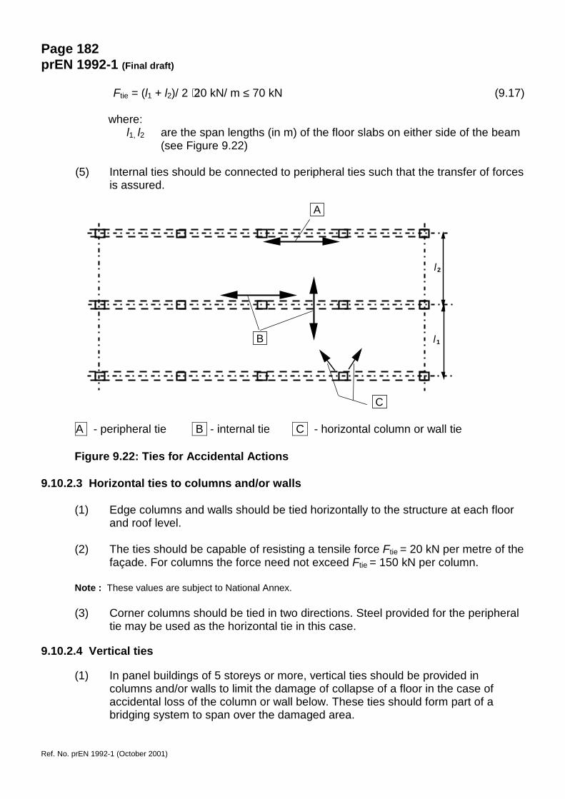
(5) Internal ties should be connected to peripheral ties such that the transfer of forcesis assured.
A - peripheral tie B - internal tie C - horizontal column or wall tie
Figure 9.22: Ties for Accidental Actions
9.10.2.3 Horizontal ties to columns and/or walls
(1) Edge columns and walls should be tied horizontally to the structure at each floorand roof level.
(2) The ties should be capable of resisting a tensile force Ftie = 20 kN per metre of thefaçade. For columns the force need not exceed Ftie = 150 kN per column.
Note : These values are subject to National Annex.
(3) Corner columns should be tied in two directions. Steel provided for the peripheraltie may be used as the horizontal tie in this case.
9.10.2.4 Vertical ties
(1) In panel buildings of 5 storeys or more, vertical ties should be provided incolumns and/or walls to limit the damage of collapse of a floor in the case ofaccidental loss of the column or wall below. These ties should form part of abridging system to span over the damaged area.
A
B
C
l1
l2

Page 183prEN 1992-1 (Final draft)
Ref. No. prEN 1992-1 (October 2001)
(2) Normally, continuous vertical ties should be provided from the lowest to thehighest level, capable of carrying the load in the accidental design situation,acting on the floor above the column/wall accidentally lost. Other solutions e.g.based on the diaphragm action remaining wall elements and/or on membraneaction in floors, may be used if equilibrium and sufficient deformation capacity canbe verified.
(3) Where a column or wall is supported at its lowest level by an element other than afoundation (e.g. beam or flat slab) accidental loss of this element should beconsidered in the design and a suitable alternative load path should be provided.
9.10.3 Continuity and anchorage of ties
(1)P Ties in two horizontal directions shall be effectively continuous and anchored at theperimeter of the structure.
(2) Ties may be provided wholly within the insitu concrete topping or at connections.Where ties are not continuous in one plane, the bending effects resulting from theeccentricities should be considered.
(3) Ties should not normally be lapped in narrow joints between precast units.Mechanical anchorage should be used in these cases.

Page 184prEN 1992-1 (Final draft)
Ref. No. prEN 1992-1 (October 2001)
SECTION 10 ADDITIONAL RULES FOR PRECAST CONCRETE ELEMENTS ANDSTRUCTURES
10.1 General
(1)P The rules in this section apply to buildings made partly or entirely of precast concreteelements, and are supplementary to the rules in other sections. Additional mattersrelated to detailing, production and assembly are covered by specific product standards.
Note: Headings are numbered 10 followed by the number of the corresponding main section. Headings of lowerlevel are numbered consecutively, without connection to sub-headings in previous sections.
10.1.1 Special terms used in this section
- precast element: element manufactured in compliance with a specific CEN productstandard or other regulatory document valid in the place of use, and in a factory or aplace other than the final position in the structure, protected from adverse weatherconditions
- composite element: element comprising in-situ and precast concrete with or withoutreinforcement connectors
- rib and block floors: consist of precast ribs (or beams) with an infill between them,made of blocks, hollow clay pots or other forms of permanent shuttering, with orwithout an in-situ topping
- diaphragms: plane members which are subjected to in-plane forces; may consist ofseveral precast units connected together
- ties: in the context of precast structures, ties are tensile members, effectivelycontinuous, placed in floors, walls or columns
- isolated precast members: members for which, in case of failure, no secondary meansof load transfer is available
- transient situations in precast concrete construction include• demoulding• transport to the storage yard• storage (support and load conditions)• transport to site• erection (hoisting)• construction (assembly)
10.2 Basis of design, fundamental requirements
(1)P In design and detailing of precast concrete elements and structures, the following shallbe considered specifically:
- transient situations (see 10.1.1)- bearings; temporary and permanent- connections and joints between elements
(2) Where relevant, dynamic effects in transient situations should be taken intoaccount. In the absence of an accurate analysis, static effects may be multipliedby an appropriate factor.
(3) Where required, mechanical devices should be detailed in order to allow ease ofassembly, inspection and replacement.
Page 185prEN 1992-1 (Final draft)
Ref. No. prEN 1992-1 (October 2001)
10.3 Materials
10.3.1 Concrete
10.3.1.1 Strength
(1) For precast elements in continuous production, subjected to an appropriatequality control system according to the product standards, with the concretetensile strength tested, a statistical analysis of test results may be used as a basisfor the evaluation of the tensile strength that is used for serviceability limit statesverifications, as an alternative to Table 3.1.
(2) Intermediate strength classes within Table 3.1 may be used.
(3) In the case of heat curing of precast concrete elements, the compressive strengthof concrete at an age t before 28 days, fcm(t), may be estimated from Expression(3.3) in which the concrete age t is substituted by the temperature adjustedconcrete age obtained by Expression (B.10) of Annex B.
Note: The coefficient βcc(t) should be limited to 1.
For the effect of heat curing Expression (10.1) may be used:
)1log()128log(
)( pp
cmpcmcmpcm +−
+−−
+= ttt
ffftf (10.1)
Where fcmp is the mean compressive strength after the heat curing (i.e. at therelease of the prestress), measured by testing of samples at the time tp (tp < t),that went through the same heat treatment with the precast elements.
10.3.1.2 Creep and shrinkage
(1) In the case of a heat curing of the precast concrete elements, it is permitted toestimate the values of creep deformations according to the maturity function,Expression (B.10) of Annex B.
(2) In order to calculate the creep deformations, the age of concrete at loading t0 (indays) in Expression (B.5) should be replaced by the equivalent concrete ageobtained by Expressions (B.9) and (B.10) of Annex B.
(3) In precast elements subject to heat during it may be assumed that:a) the shrinkage strain is not significant andb) autogenous shrinkage strain is nil.
10.3.2 Prestressing steel
10.3.2.2 Technological properties of prestressing steel
(1)P For pre-tensioned members, the effect on the relaxation losses of increasing thetemperature while curing the concrete, shall be considered.
Note: The relaxation is accelerated during the application of a thermal curing when a thermal strain is introducedat the same time. Finally, the relaxation rate is reduced at the end of the treatment.
Page 186prEN 1992-1 (Final draft)
Ref. No. prEN 1992-1 (October 2001)
(2) An equivalent time teq should be added to the time after tensioning t in therelaxation time functions, given in 3.3.2(7), to cater for the effects of the heattreatment on the prestress loss due to the relaxation of the prestressing steel. Theequivalent time can be estimated from Expression (10.3):
( )( ) i1
∆max
20
eq ∆2020
14,1i
max
tTT
tn
it
T
� −−
==
−
(10.3)
where teq is the equivalent time (in hours)T(∆ti) is the temperature (in °C) during the time interval ∆tiTmax is the maximum temperature (in °C) during the heat treatment
10.5 Structural analysis, general provisions
10.5.1 General
(1)P The analysis shall account for:
- the behaviour of the structural units at all stages of construction using the appropriategeometry and properties for each stage, and their interaction with other elements (e.g.composite action with in-situ concrete, other precast units);
- the behaviour of the structural system influenced by the behaviour of the connectionsbetween elements, with particular regard to actual deformations and strength ofconnections;
- the uncertainties influencing restraints and force transmission between elementsarising from deviations in geometry and in the positioning of units and bearings.
(2) Beneficial effects of horizontal restraint caused by friction due to the weight of anysupported element may only be used in non seismic zones (using γG,inf) andwhere:- the friction is not solely relied upon for overall stability of the structure;- the bearing arrangements preclude the possibility of accumulation of irreversible
sliding of the elements, such as caused by uneven behaviour under alternateactions (e.g. cyclic thermal effects on the contact edges of simply supportedelements);
- the possibility of significant impact loading is eliminated
(3) The effects of horizontal movements should be considered in design with respectto the resistance of the structure and the integrity of the connections.
10.5.2 Losses of prestress
(1) In the case of heat curing of precast concrete elements, the lessening of thetension in the tendons and the restrained dilatation of the concrete due to thetemperature, induce a specific thermal loss ∆Pθ. This loss may be estimated bythe Expression (10.4):
Page 187prEN 1992-1 (Final draft)
Ref. No. prEN 1992-1 (October 2001)
)(5,0∆ omaxcppθ TTEAP −= α (10.4)Where
Ap is the cross-section of tendonsEp is the elasticity modulus of tendonsαc is the linear coefficient of thermal expansion for concrete (see 3.1.2)Tmax − T0 is the difference between the maximum and initial temperature in
the concrete near the tendons, in °C
Note: Any loss of prestress, ∆Pθ, caused by elongation due to heat curing may be ignored if preheating ofthe tendons is applied.
10.9 Particular rules for design and detailing
10.9.1 Restraining moments in slabs
(1) Restraining moments may be resisted by top reinforcement placed in the toppingor in plugs in open cores of hollow core units. In the former case the horizontalshear in the connection should be checked according to 6.2.5. In the latter casethe transfer of force between the in situ concrete plug and the hollow core unitshould be verified according to 6.2.5. The length of the top reinforcement shouldbe in accordance with 9.2.1.3.
(2) Unintended restraining effects at the supports of simply supported slabs shouldbe considered by special reinforcement and/or detailing.
10.9.2 Wall to floor connections
(1) In wall elements installed over floor slabs, reinforcement should normally beprovided for possible eccentricities and concentrations of the vertical load at theend of the wall. For floor elements see 10.9.1 (2).
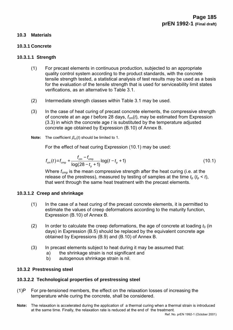
(2) No specific reinforcement is required provided the vertical load is ≤ 0,5h.fcd, whereh is the wall thickness, see Figure 10.1. The load may be increased to 0,6h.fcdwith reinforcement according to Figure 10.1, having diameter φ ≥ 6 mm andspacing s not greater than the lesser of h and 200 mm. For higher loads,reinforcement should be designed according to (1).
Figure 10.1: Example of reinforcement in a wall over a connection between twofloor slabs.
sh
φ
Page 188prEN 1992-1 (Final draft)
Ref. No. prEN 1992-1 (October 2001)
10.9.3 Floor systems
(1)P The detailing of floor systems shall be consistent with assumptions in analysis anddesign. Relevant product standards shall be considered.
(2)P Where transverse load distribution between adjacent units has been taken into account,appropriate shear connection shall be provided.
(3)P The effects of possible restraints of precast units shall be considered, even if simplesupports have been assumed in design.
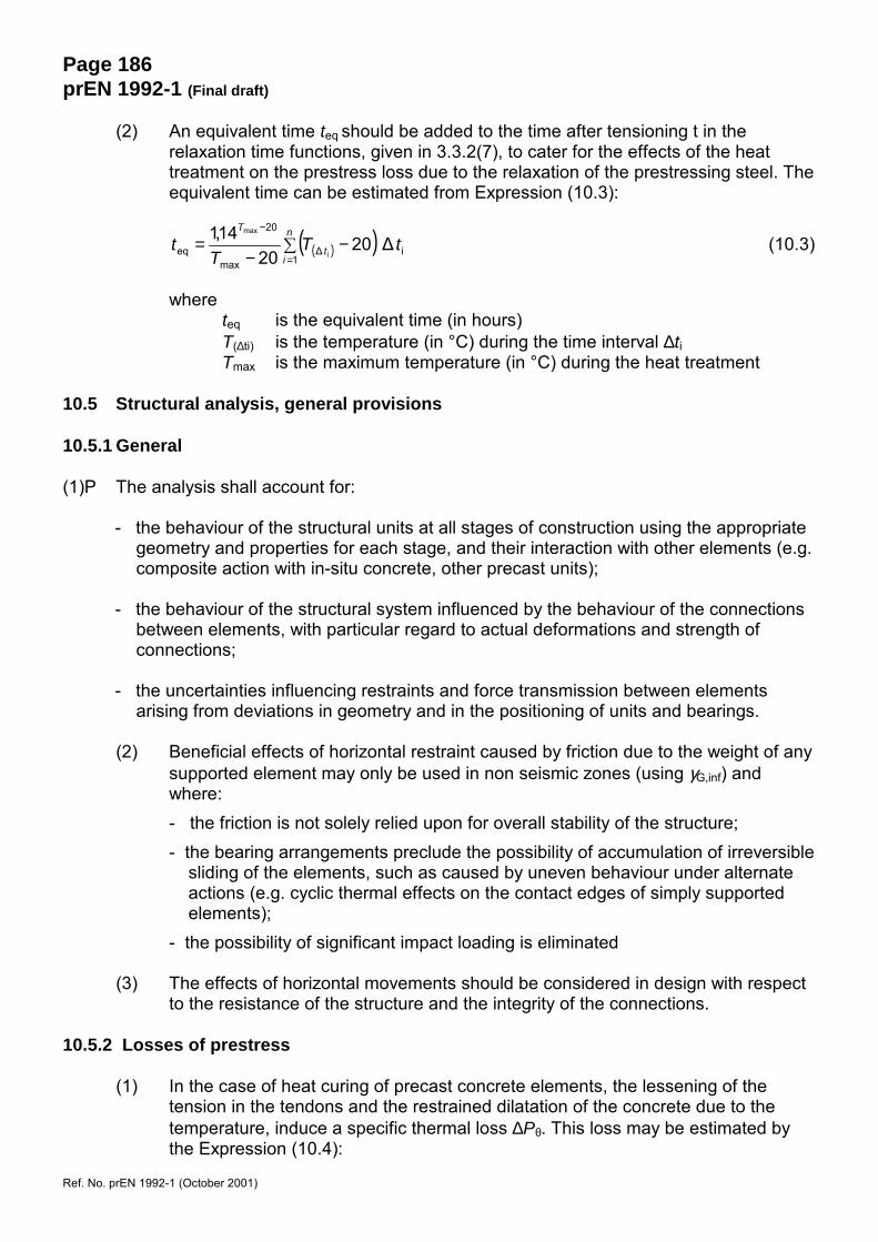
(4) Shear transfer in connections may be achieved in different ways. Three maintypes shown in Figure 10.2.
(5) Transverse distribution of loads should be based on analysis or tests, taking intoaccount possible load variations between precast elements. The resulting shearforce between floor units should be considered in the design of connections andadjacent parts of elements (e.g. outside ribs or webs).
For floors with uniformly distributed load, and in the absence of a more accurateanalysis, this shear force may be taken as:
vEd = qEd⋅be (10.5)
where: qEd is the design value of imposed loadbe is the length along the connection and may be taken as 0,5 m
a) concreted or groutedconnections
b) welded or boltedconnections (this showsone type of weldedconnection as anexample)
c) reinforced topping.(vertical reinforcementconnectors to topping maybe required to ensureshear transfer at ULS)
Figure 10.2: Examples of connections for shear transfer
(6) Where precast floors are assumed to act as diaphragms to transfer horizontalloads to bracing units, the following should be considered:- the diaphragm should form part of a realistic structural model, taking into
account the deformation compatibility with bracing units,- the effects of horizontal deformations should be taken into account for all
parts of the structure involved in the transfer of horizontal loads,- the diaphragm should be reinforced for the tensile forces assumed in the
structural model,- stress concentrations at openings and connections should be taken into
account in the detailing of reinforcement.
Page 189prEN 1992-1 (Final draft)
Ref. No. prEN 1992-1 (October 2001)
(7) Transverse reinforcement for shear transfer across connections in the diaphragmmay be concentrated along supports, forming ties consistent with the structuralmodel. This reinforcement may be placed in the topping, if it exists.
(8) Precast units with a topping of at least 40 mm may be designed as compositemembers, if shear in the interface is verified according to 6.2.5. The precast unitshould be checked at all stages of construction, before and after composite actionhas become effective.
(9) Transverse reinforcement for bending and other action effects may lie entirelywithin the topping. The detailing should be consistent with the structural model,e.g. if two-way spanning is assumed.
(10) Webs or ribs in isolated slab units (i.e. units which are not connected for sheartransfer) should be provided with shear reinforcement as for beams.
(11) Floors with ribs and blocks without topping may be analysed as solid slabs, ifthere are transverse ribs at a spacing sT according to Table 10.1.
(12) In diaphragm action between slab elements, the average longitudinal shear stressvRdi should be limited to 0,1 MPa for very smooth surfaces, and to 0,15 MPa forsmooth and rough surfaces.
Table 10.1: Maximum spacing of transverse ribs for the analysis of floors with ribsand block as solid slabs. sL = spacing of longitudinal ribs, lL = length(span) of longitudinal ribs, d = thickness of ribbed floor
Type of imposed loading sL ≤ lL/8 sL > lL/8
Residential load, snow load not relevant sT ≤ 12 d
Other loads sT ≤ 10 d sT ≤ 8 d
10.9.4 Connections and supports for precast elements
10.9.4.1 Materials
(1)P Materials used for connections shall be:- stable and durable for the lifetime of the structure- chemically and physically compatible- protected against adverse chemical and physical influences- fire resistant to match the fire resistance of the structure.
(2)P Supporting pads shall have strength and deformation properties in accordance with the
design assumptions. (3)P Metal fastenings for claddings, other than in environmental classes X0 and XC1
(Table 4.1) and not protected against the environment, shall be of corrosion resistantmaterial. If inspection is possible, coated material may also be used.
Page 190prEN 1992-1 (Final draft)
Ref. No. prEN 1992-1 (October 2001)
(4)P Before undertaking welding, annealing or cold forming the suitability of the material shallbe verified.
10.9.4.2 General rules for design and detailing of connections (1)P Connections shall be able to resist action effects consistent with design assumptions, to
accommodate the necessary deformations and ensure robust behaviour of the structure. (2)P Premature splitting or spalling of concrete at the ends of elements shall be prevented,
taking into account- relative movements between elements- tolerances- assembly requirements- ease of execution- ease of inspection
(3) Resistance and stiffness of connections may be based on analysis or tests.Imperfections should be taken into account. Design values based on tests shouldallow for unfavourable deviations from testing conditions.
10.9.4.3 Connections transmitting compressive forces
(1) Shear forces may be ignored in compression connections if they are less than10% of the compressive force.
(2) For connections with bedding materials like mortar, concrete or polymers, relativemovement between the connected surfaces should be prevented duringhardening of the material.
(3) Connections without bedding material (dry connections) should only be usedwhere an appropriate quality of workmanship can be achieved. The average bea-ring stress between plane surfaces should not exceed 0,3 fcd. Dry connectionsincluding curved (convex) surfaces should be designed with due consideration ofthe geometry.
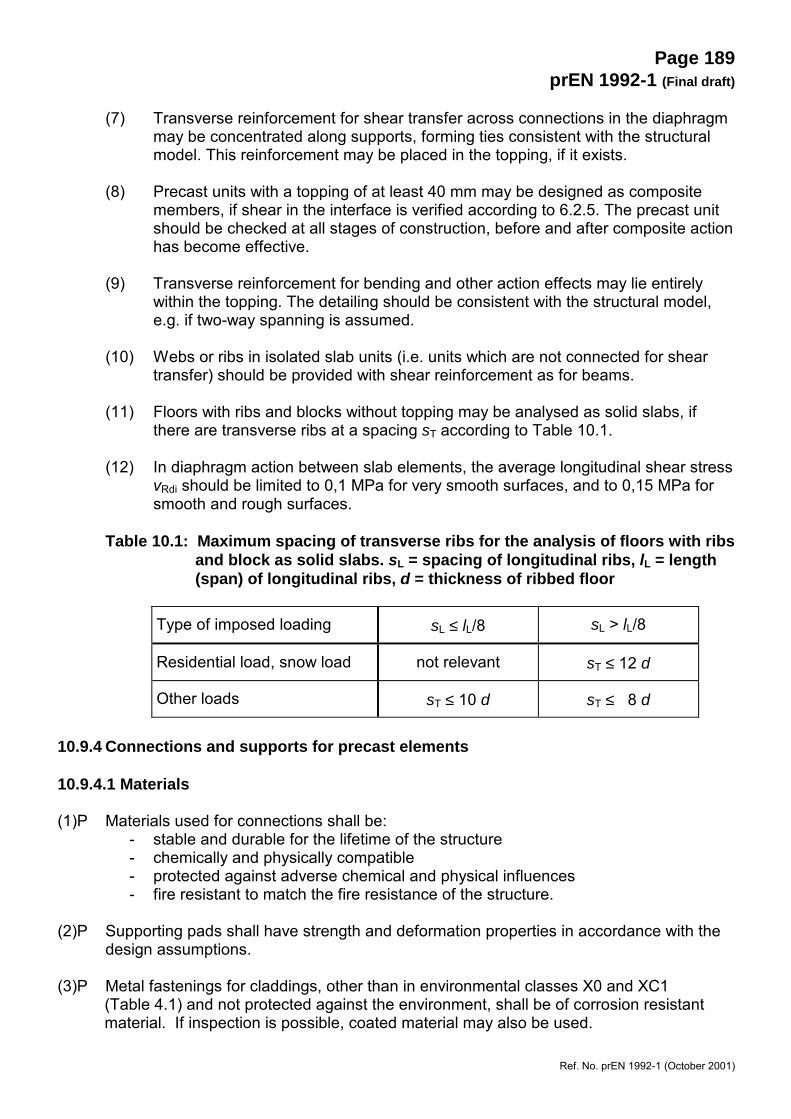
(4) Transverse tensile stresses in adjacent elements should be considered. Theymay be due to concentrated compression according to Figure 10.3a, or to theexpansion of soft padding according to Figure 10.3b. Reinforcement in case a)may be designed and located according to 6.5. Reinforcement in case b) shouldbe placed close to the surfaces of the adjacent elements.
(5) In the absence of more accurate models, reinforcement in case b) may becalculated in accordance with Expression (10.6):
As = 0,25 (t / h) FEd / fyd (10.6)
where:As reinforcement area in each surfacet thickness of paddingh dimension in direction of reinforcement FEd compressive force in connection
Page 191prEN 1992-1 (Final draft)
Ref. No. prEN 1992-1 (October 2001)
a) Concentrated bearing b) Expansion of soft padding
Figure 10.3: Transverse tensile stresses at compression connections.
(6) The maximum capacity of compression connections can be determined accordingto 6.7, or by testing, see 6.2.5.
10.9.4.4 Connections transmitting shear forces
(1) For shear transfer in interfaces between two concretes, e.g. a precast elementand in situ concrete, see 6.2.5.
10.9.4.5 Connections transmitting bending moments or tensile forces
(1)P Reinforcement shall be continuous across the connection and anchored in the adjacentelements.
(2) Continuity may be obtained by, for example- lapping of bars- grouting of reinforcement into holes- overlapping reinforcement loops- welding of bars or steel plates- prestressing- mechanical devices (threaded or filled sleeves)- swaged connectors
10.9.4.6 Half joints
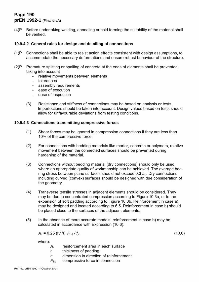
(1) Half joints may be designed using strut-and-tie models according to 6.5. Twoalternative models and reinforcements are indicated in Figure 10.4. The twomodels may be combined.
Page 192prEN 1992-1 (Final draft)
Ref. No. prEN 1992-1 (October 2001)
Note: The figure shows only the main features of strut-and-tie models.
Figure 10.4: Indicative models for reinforcement in half joints.
10.9.4.7 Anchorage of reinforcement at supports
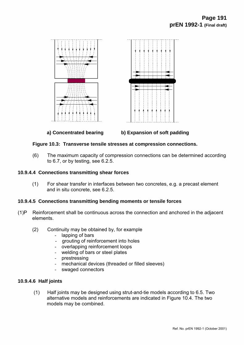
(1) Reinforcement in supporting and supported members should be detailed toensure anchorage in the respective node, allowing for tolerances. An example isshown in Figure 10.5.
The effective bearing length a1 is controlled by a distance d (see Figure 10.5)from the edge of the respective elements where:
d = c + ∆a2 with horizontal loops or otherwise end anchored barsd = c + ∆a2+ r with vertically bent bars
Here c is concrete cover and ∆a2 is a tolerance; see Figure 10.5 and 10.9.6.2 fordefinitions.
Figure 10.5: Example of detailing of reinforcement in support
10.9.5 Bearings
10.9.5.1 General
(1)P The proper functioning of bearings shall be ensured by reinforcement in adjacentmembers, limitation of bearing stress and measures to account for movement orrestraint.
r
d c> a + ∆a1 3
c
r
> a + ∆a1 2 d
Page 193prEN 1992-1 (Final draft)
Ref. No. prEN 1992-1 (October 2001)
(2)P For bearings which do not permit sliding or rotation without significant restraint, actionsdue to creep, shrinkage, temperature, misalignment, lack of plumb etc. shall be takeninto account in the design of adjacent members.
(3) The effects of (2)P may require transverse reinforcement in supporting andsupported members, and/or continuity reinforcement for tying elements together.They may also influence the design of main reinforcement in such members.
(4)P Bearings shall be designed and detailed to ensure correct positioning, taking intoaccount production and assembling tolerances.
(5)P Possible effects of prestressing anchorages and their recesses shall be taken intoaccount.
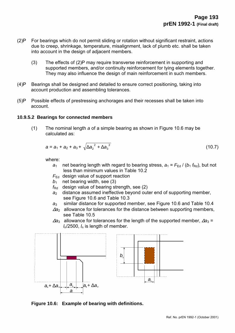
10.9.5.2 Bearings for connected members
(1) The nominal length a of a simple bearing as shown in Figure 10.6 may becalculated as:
a = a1 + a2 + a3 + 23
22 aa ∆+∆ (10.7)
where:a1 net bearing length with regard to bearing stress, a1 = FEd / (b1 fRd), but not
less than minimum values in Table 10.2FEd design value of support reactionb1 net bearing width, see (3)fRd design value of bearing strength, see (2)a2 distance assumed ineffective beyond outer end of supporting member,
see Figure 10.6 and Table 10.3a3 similar distance for supported member, see Figure 10.6 and Table 10.4∆a2 allowance for tolerances for the distance between supporting members,
see Table 10.5∆a3 allowance for tolerances for the length of the supported member, ∆a3 =
ln/2500, ln is length of member.
Figure 10.6: Example of bearing with definitions.
a + ∆a2 2a1
aa + ∆a3 3
b1
a1
Page 194prEN 1992-1 (Final draft)
Ref. No. prEN 1992-1 (October 2001)
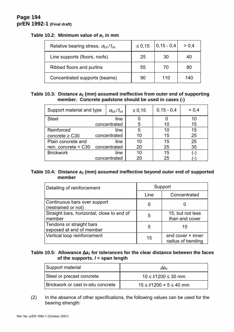
Table 10.2: Minimum value of a1 in mm
Relative bearing stress, σEd / fcd ≤ 0,15 0,15 - 0,4 > 0,4
Line supports (floors, roofs) 25 30 40
Ribbed floors and purlins 55 70 80
Concentrated supports (beams) 90 110 140
Table 10.3: Distance a2 (mm) assumed ineffective from outer end of supportingmember. Concrete padstone should be used in cases (-)
Support material and type σEd / fcd ≤ 0,15 0,15 - 0,4 > 0,4
Steel line 0 0 10concentrated 5 10 15
Reinforced line 5 10 15concrete ≥ C30 concentrated 10 15 25Plain concrete and line 10 15 25rein. concrete < C30 concentrated 20 25 35Brickwork line 10 15 (-)
concentrated 20 25 (-)
Table 10.4: Distance a3 (mm) assumed ineffective beyond outer end of supportedmember
Detailing of reinforcement Support
Line ConcentratedContinuous bars over support(restrained or not) 0 0
Straight bars, horizontal, close to end ofmember 5 15, but not less
than end coverTendons or straight barsexposed at end of member 5 15
Vertical loop reinforcement 15 end cover + innerradius of bending
Table 10.5: Allowance ∆∆∆∆a2 for tolerances for the clear distance between the facesof the supports. l = span length
Support material ∆a2
Steel or precast concrete 10 ≤ l/1200 ≤ 30 mm
Brickwork or cast in-situ concrete 15 ≤ l/1200 + 5 ≤ 40 mm
(2) In the absence of other specifications, the following values can be used for thebearing strength:

Page 195prEN 1992-1 (Final draft)
Ref. No. prEN 1992-1 (October 2001)
fRd = 0,4 fcd for dry connections (see 10.9.5.3 (3) for definition)
fRd = fbed ≤ 0,85 fcd for all other cases
wherefcd the lowest design strength of supported and supporting memberfbed design strength of bedding material
(3) If measures are taken to obtain a uniform distribution of the bearing pressure, e.g.with mortar, neoprene or similar pads, the design bearing width b1 may be takenas the actual width of the bearing. Otherwise, and in the absence of a moreaccurate analysis, b1 should be limited to 600 mm.
10.9.5.3 Bearings for isolated members
(1)P The nominal length shall be 20 mm greater than for non-isolated members.
(2)P If the bearing allows movements in the support, the net bearing length shall be increasedto cover possible movements.
(3)P If a member is tied other than at the level of its bearing, the net bearing length a1 shallbe increased to cover the effect of possible rotation around the tie.
10.9.6 Pocket foundations
(1)P Concrete pockets shall be capable of transferring vertical actions, bending moments andhorizontal shears from columns to the soil. The pocket shall be large enough to enable agood concrete filling below and around the column.
10.9.6.1 Pockets with keyed surfaces
(1) Pockets expressly wrought with indentations or keys may be considered to actmonolithically with the column.
(2) Where vertical tension due to moment transfer occurs careful detailing of theoverlap reinforcement of the column and the foundation is needed, allowing forthe separation of the lapped bars. The lap length according to 8.6 should beincreased by at least the horizontal distance between bars in the column and inthe foundation (see Figure 10.7 (a) ) Adequate horizontal reinforcement for thelapped splice should be provided.
(3) The punching shear design should be as for monolithic column/foundationconnections according to 6.4, as shown in Figure 10.7 (a), provided the sheartransfer between the column and footing is verified. Otherwise the punchingshear design should be as for pockets with smooth surfaces.
Page 196prEN 1992-1 (Final draft)
Ref. No. prEN 1992-1 (October 2001)
10.9.6.2 Pockets with smooth surfaces
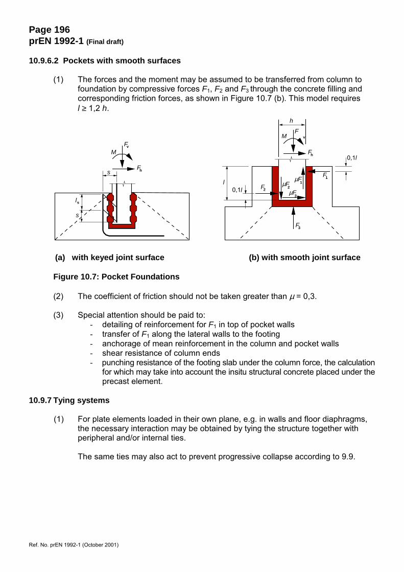
(1) The forces and the moment may be assumed to be transferred from column tofoundation by compressive forces F1, F2 and F3 through the concrete filling andcorresponding friction forces, as shown in Figure 10.7 (b). This model requiresl ≥ 1,2 h.
(a) with keyed joint surface (b) with smooth joint surface
Figure 10.7: Pocket Foundations
(2) The coefficient of friction should not be taken greater than µ = 0,3.
(3) Special attention should be paid to:- detailing of reinforcement for F1 in top of pocket walls- transfer of F1 along the lateral walls to the footing- anchorage of mean reinforcement in the column and pocket walls- shear resistance of column ends- punching resistance of the footing slab under the column force, the calculation
for which may take into account the insitu structural concrete placed under theprecast element.
10.9.7 Tying systems
(1) For plate elements loaded in their own plane, e.g. in walls and floor diaphragms,the necessary interaction may be obtained by tying the structure together withperipheral and/or internal ties.
The same ties may also act to prevent progressive collapse according to 9.9.
ls
s
s
M
F
Fv
h
MF
v
Fh
h
F1
F2
F3
µF2
µF1
µF3
0,1l
0,1ll
Page 197prEN 1992-1 (Final draft)
Ref. No. prEN 1992-1 (October 2001)
SECTION 11 LIGHTWEIGHT AGGREGATE CONCRETE STRUCTURES
11.1 General
(1)P This section provides additional requirements for lightweight aggregate concrete.Reference is made to the other Sections (1 to 9 and 11) of this document and theAnnexes.
Note. Headings are numbered 11 followed by the number of thecorresponding main section. Headings of lowerlevel are numbered consecutively, without connection to sub-headings in previous sections. If alternativesare given for Expressions, Figures or Tables in the other sections, the original reference numbers are alsoprefixed by 11.
11.1.1 Scope
(1)P All clauses of the Sections 1 to 9 and 11 are generally applicable, unless they aresubstituted by special clauses given in this section. In general, where strength valuesoriginating from Table 3.1 are used in Expressions, those values have to be replaced bythe corresponding values for lightweight concrete, given in this section in Table 11.3.1
(2)P Section 10 applies to all concretes with closed structure made with natural or artificialmineral lightweight aggregates, unless reliable experience indicates that provisionsdifferent from those given can be adopted safely.
(3) This section does not apply to aerated concrete either autoclaved or normallycured nor lightweight aggregate concrete with an open structure.
(4)P Lightweight aggregate concrete is concrete having a closed structure and an oven-drydensity of not more than 2200 kg/m3 consisting of or containing a proportion of artificialor natural lightweight aggregates having a particle density of less than 2000 kg/m3
11.1.7 Special symbols
1(P) The following symbols are used specially for lightweight concrete:
LC The strength classes of lightweight aggregate concrete are preceded by thesymbol LC
ηE conversion factor for calculating the modulus of elasticityη1 coefficient for determining tensile strengthη2 coefficient for determining creep coefficientη3 coefficient for determining drying shrinkageρ oven-dry density of lightweight aggregate concrete in kg/m3
For the mechanical properties an additional subscript l (lightweight) is used.
11.2 Basis of design
1(P) Section 2 is valid for lightweight concrete without modifications.
Page 198prEN 1992-1 (Final draft)
Ref. No. prEN 1992-1 (October 2001)
11.3 Materials
11.3.1 Concrete
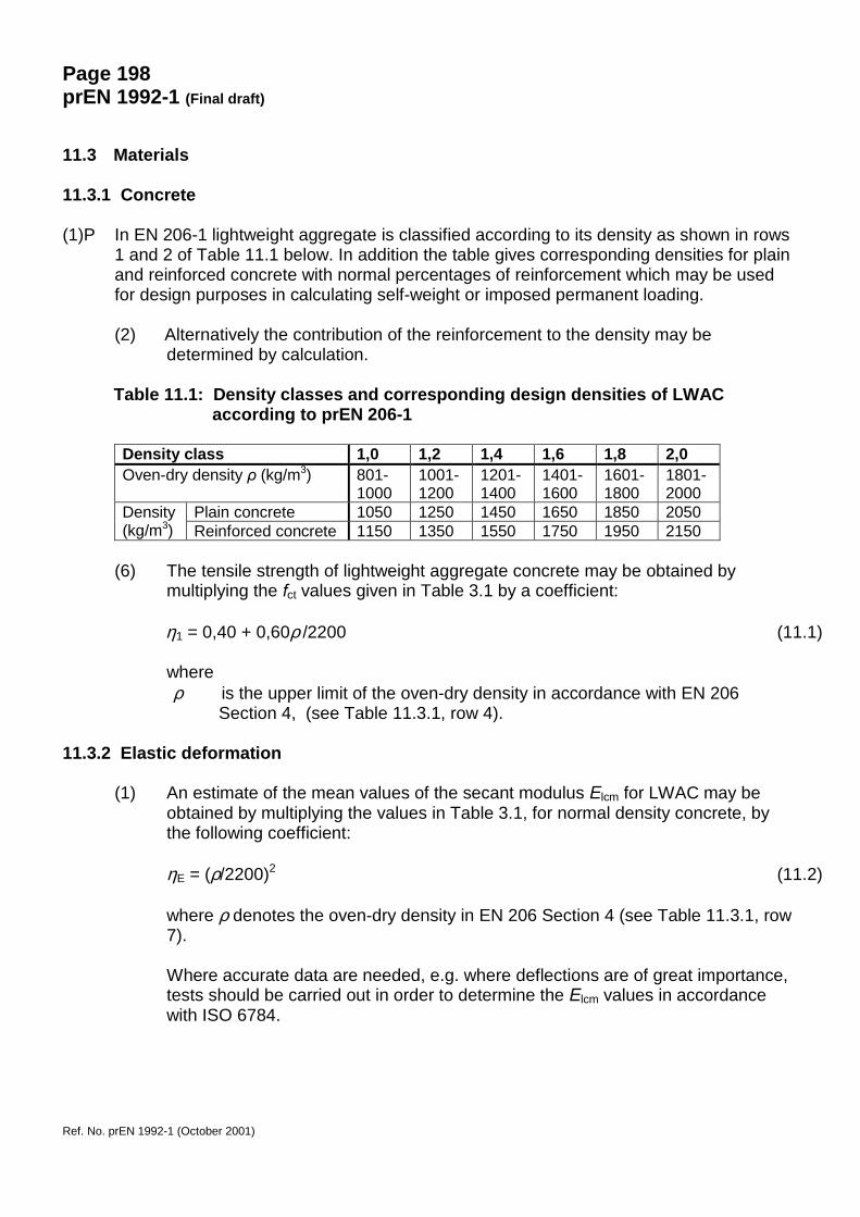
(1)P In EN 206-1 lightweight aggregate is classified according to its density as shown in rows1 and 2 of Table 11.1 below. In addition the table gives corresponding densities for plainand reinforced concrete with normal percentages of reinforcement which may be usedfor design purposes in calculating self-weight or imposed permanent loading.
(2) Alternatively the contribution of the reinforcement to the density may bedetermined by calculation.
Table 11.1: Density classes and corresponding design densities of LWACaccording to prEN 206-1
Density class 1,0 1,2 1,4 1,6 1,8 2,0Oven-dry density ρ (kg/m3) 801-
10001001-1200
1201-1400
1401-1600
1601-1800
1801-2000
Plain concrete 1050 1250 1450 1650 1850 2050Density(kg/m3) Reinforced concrete 1150 1350 1550 1750 1950 2150
(6) The tensile strength of lightweight aggregate concrete may be obtained bymultiplying the fct values given in Table 3.1 by a coefficient:
η1 = 0,40 + 0,60ρ /2200 (11.1)
whereρ is the upper limit of the oven-dry density in accordance with EN 206
Section 4, (see Table 11.3.1, row 4).
11.3.2 Elastic deformation
(1) An estimate of the mean values of the secant modulus Elcm for LWAC may beobtained by multiplying the values in Table 3.1, for normal density concrete, bythe following coefficient:
ηE = (ρ/2200)2 (11.2)
where ρ denotes the oven-dry density in EN 206 Section 4 (see Table 11.3.1, row7).
Where accurate data are needed, e.g. where deflections are of great importance,tests should be carried out in order to determine the Elcm values in accordancewith ISO 6784.
Page 199prEN
1992-1 (Final draft)
Ref. N
o. prEN 1992-1 (O
ctober 2001)
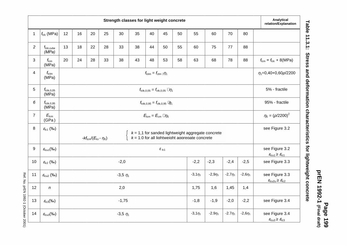
Table 11.3.1: Stress and deformation characteristics for lightw
eight concrete
Analyticalrelation/Explanation
flcm = flck + 8(MPa)
η1=0,40+0,60ρ/2200
5% - fractile
95% - fractile
ηE = (ρ/2200)2
see Figure 3.2
see Figure 3.2εlcu1 ≥ εlc1
see Figure 3.3
see Figure 3.3εlcu2u ≥ εlc2
see Figure 3.4
see Figure 3.4εlcu3 ≥ εlc3
80
88
88
-2,5
-2,6η1
1,4
-2,2
-2,6η1
70
77
78
-2,4
-2,7η1
1,45
-2,0
-2.7η1
60
75
68
-2,3
-2,9η1
1,6
-1,9
-2.9η1
55
60
63
-2,2
-3,1η1
1,75
-1,8
-3,1η1
50
55
58
45
50
53
40
44
48
35
38
43
30
33
38
25
28
33
20
22
28
16
18
24
12
13
20
flctm = fctm ⋅ η1
flctk,0,05 = fctk,0,05 ⋅ η1
flctk,0,95 = fctk,0,95 ⋅η1
Elcm = Ecm ⋅ ηE
-kflcm/(Elci - ηE)
�
ε lc1
-2,0
-3,5 η1
2,0
-1,75
-3,5 η1
flck (MPa)
flck,cube(MPa)
flcm(MPa)
flctm(MPa)
flctk,0,05(MPa)
flctk,0,95(MPa)
Elcm(GPa )
εlc1 (‰)
εlcu1(‰)
εlc2 (‰)
εlcu2 (‰)
n
εlc3(‰)
εlcu3(‰)
Strength classes for light weight concrete
1
2
3
4
5
6
7
8
9
10
11
12
13
14
k = 1,1 for sanded lightweight aggregate concretek = 1,0 for all lightweight aggregate concrete
Page 200prEN 1992-1 (Final draft)
Ref. No. prEN 1992-1 (October 2001)
(4)P The coefficient of thermal expansion of LWAC depends mainly on the type of aggregateused and varies over a wide range between about 4⋅10-6 and 14⋅10-6/K
For design purposes where thermal expansion is of no great importance, the coefficientof thermal expansion may be taken as 8⋅10-6/K.
The differences between the coefficients of thermal expansion of steel and lightweightaggregate concrete need not be considered in design.
11.3.3 Creep and shrinkage
(1) For lightweight aggregate concrete the creep coefficient φ may be assumed equalto the value of normal density concrete multiplied by a factor (ρ /2200)2.
The creep strains so derived should be multiplied by a factor η2:
η2 = 1,3 for flck ≤ LC16/20 = 1,0 for flck ≥ LC20/25
(2) The final drying shrinkage values for lightweight concrete can be obtained bymultiplying the values for normal density concrete in Table 3.2 by a factor η3:
η3 = 1,5 for flck ≤ LC16/20 = 1,2 for flck ≥ LC20/25
(3) The Expressions (3.10) and (3.11), which provide information for autogenousshrinkage, give maximum values for lightweight aggregate concretes, where nosupply of water from the aggregate to the drying microstructure is possible. Ifwater-saturated, or even partially saturated lightweight aggregate is used, theautogenous shrinkage values will be considerably reduced.
11.3.4 Stress-strain relations for structural analysis
(1) For lightweight aggregate concrete the values εc1 and εcu1 given in Figure 3.2should be substituted by ε lc1 and ε lcu1 given in Table 11.3.1.
11.3.5 Design compressive and tensile strengths
(1)P The value of the design compressive strength is defined as:
flcd = αlcc flck / γc (11.3.15)
where γc is the partial safety factor for concrete, see 2.4.1.4, and αlcc is a coefficientaccording to 3.1.6 (1)P which may be assumed to be 0,85, unless specified otherwise.
(2)P The value of the design tensile strength is defined as
flctd = αlct flctk / γc (11.3.16)
Page 201prEN 1992-1 (Final draft)
Ref. No. prEN 1992-1 (October 2001)
where γc is the partial safety factor for concrete, see 2.4.1.4 and αlct is a coefficient according to3.1.6 (2)P, which may be assumed to be 0,85 unless specified otherwise.
Note: The values of αlcc and αlct are subject to a National Annex.
11.3.6 Stress-strain relations for the design of sections
(1) For lightweight aggregate concrete the values εc2 and εcu2 given in Figure 3.3should be replaced with the values of εlc2 and εlcu2 given in Table 11.3.1.
(2) For lightweight aggregate concrete the values εc3 and εcu3 given in Figure 3.4should be replaced with the values of εlc3 and εlcu3 given in Table 11.3.1.
11.3.7 Confined concrete
(2) If more precise data are not available, the stress-strain relation shown inFigure 3.6 may be used, with increased characteristic strength and strainsaccording to:
flck,c = flck (1,0 + kσ2/flck) (11.3.24)
with k = 1,1 for sanded lightweight aggregate concretek = 1,0 for all lightweight aggregate concrete
εlc2,c = εlc2 (flckc/flck)2 (11.3.26)εlcu2,c = εlcu2 + 0,2σ2/flck (11.3.27)
where εlc2 and εlcu2 follow from Table 11.3.1.
11.4 Durability and cover to reinforcement
11.4.1 Environmental conditions
(2) For lightweight aggregate concrete in Table 4.1 the same indicative strengthclasses can be used as for normal density concrete.
11.4.2 Concrete cover and properties of concrete
(3/4)P For lightweight aggregate concrete the values of minimum concrete cover given inTable 4.2 shall be increased by 5 mm.
11.5 Structural analysis
1(P) This section is valid for lightweight aggregate concrete without modification.

Page 202prEN 1992-1 (Final draft)
Ref. No. prEN 1992-1 (October 2001)
11.6 Ultimate limit states
11.6.1 Members not requiring design shear reinforcement
(1) The design value of the shear capacity of a lightweight concrete member withoutshear reinforcement VlRd,ct follows from:
(2)
VlRd,ct = [c
15,0γ
η1k(100ρl flck)1/3 – 0,15 σcp] bwd ≥ dbσf wcplctd )15,035,0( − (11.6.2)
where ρ 1 need not be taken smaller than 0,5%,
η1 is defined in Expression (11.1) and flck is taken from Table 11.3.1.
(5) At a distance 0,5d ≤ x< 2,0d from the edge of a support the shear capacity may beincreased to:
VlRd,ct = [c
15,0γ
η1k (100ρl flck)1/3 (xd2 ) – 0,15 σcp]bwd (11.6.4)
where η1 is defined in Expression (11.1), flck is taken from Table 11.3.1 and νfollows from Expression (11.6.5).
11.6.2.4 Members requiring design shear reinforcement
(3) The reduction factor ν for the crushing capacity of the concrete struts is
ν = 0,50η1 (1 – flck/250) (11.6.5)
11.6.3 Torsion
11.6.3.2 Design procedure
(3) In Expression (6.30) for lightweight concrete ν is defined according to Expression(11.6.5)
11.6.4 Punching
11.6.4.4 Slabs or column bases without punching shear reinforcement
(1) The punching shear resistance per unit area of a lightweight concrete slab followsfrom
VRd,c = cγ15,0 k η1(100ρl flck )1/3 – 0,10σcp ≥ (0,4flctd – 0,10σcp) (11.6.48)
where η1 is defined in Expression (11.1)
(4) The punching shear capacity of lightweight concrete column bases follows from
Page 203prEN 1992-1 (Final draft)
Ref. No. prEN 1992-1 (October 2001)
VlRd = c
15,0γ
η1k (100ρl flck)1/3 2d/a ≥ adf 24,0 lctd ⋅ (11.6.51)
where η1 is defined in Expression (11.1), and ρ1 ≥ 0,005
11.6.4.5 Slabs or column bases containing punching shear reinforcement
(1) In the zone with shear reinforcement the punching shear resistance is given by
αsin15,175,0 ywdsw1r
lRd,clRd,cs fAduS
dvv ���
����
����
����
�+= (11.6.53)
where vlRd,c is defined in Expression (11.6.48)
(2) Adjacent to the column the punching shear capacity is limited to a maximum of
lcdmax,lRdEd
Ed 5,0 fvdu
Vv0
ν=≤= (11.6.54)
where ν is defined in Expression (11.6.5)
11.6.5 Partially loaded areas
(1) For a uniform distribution of load on an area Ac0 (see Figure 6.29) theconcentrated resistance force may be determined as follows:
[ ] ��
���
�⋅⋅≤⋅⋅=2200
0,3/ 0clcd44000c1clcd0cRduρρ
AfAAfAF (11.6.67)
11.7 Serviceability limit states
(1)P The basic ratios of span/effective depth for reinforced concrete members without axialcompression, given in Table 7.4, should be reduced by a factor 15.0
Eη when applied toLWAC.
11.8 Detailing of reinforcement - General
11.8.1 Permissible mandrel diameters for bent bars
(2) For normal density concrete the mandrel size should be restricted to the valuesgiven in Table 8.2, in order to avoid splitting of the concrete behind bends, hooksand loops. For lightweight aggregate concrete those values should be increasedby 50%.
Page 204prEN 1992-1 (Final draft)
Ref. No. prEN 1992-1 (October 2001)
11.8.2 Ultimate bond stress
(2) The design value of the ultimate bond stress for bars in lightweight concrete maybe calculated using Expression 8.2, by substituting the value flcd for fcd, withflcd = flctk,0,05/γc. The values for flctk,0,05 are found in Table 11.3.1.
11.9 Detailing of members and particular rules
(1) The diameter of bars embedded in LWAC should not normally exceed 32 mm. ForLWAC bundles of bars should not consist of more than two bars.
11.12 Plain and lightly reinforced concrete structures
(1)P This section shall be applied to lightweight aggregate concrete without modifications.
Page 205prEN 1992-1 (Final draft)
Ref. No. prEN 1992-1 (October 2001)
SECTION 12 PLAIN AND LIGHTLY REINFORCED CONCRETE STRUCTURES
12.1 General
(1)P This section provides additional rules for plain and lightly reinforced concrete structures.
Note: Headings are numbered 12 followed by the number of the corresponding main section. Headings of lowerlevel are numbered consecutively, without reference to subheadings in previous sections.
(2) This Section applies to members, for which the effect of dynamic actions may beignored. It does not apply to the effects such as those from rotating machines andtraffic loads. It includes such members as:
- plain concrete members mainly subjected to compression other than that due toprestressing, e.g. walls, columns, arches, vaults, and tunnels;
- plain concrete strip and pad footings for foundations;
- plain concrete retaining walls;
- piles whose diameter is ≥ 600 mm and where NEd/Ac ≤ 0,3fck.
(3) Where members are made with lightweight aggregate concrete with closedstructure according to Section 11 or for precast concrete elements and structurescovered by this Standard, the design rules should be modified accordingly.
(4) Members using plain concrete do not preclude the provision of steelreinforcement needed to satisfy serviceability and/or durability requirements, norreinforcement in certain parts of the members. This reinforcement may be takeninto account for the verification of local ultimate limit states as well as for thechecks of the serviceability limit states.
12.2 Basis of design
12.2.1 Additional partial safety factors for materials
(1)P Due to the less ductile properties of plain concrete, αcc in Expression (3.13) shall betaken as 0,8 and αct in Expression (3.4) should both be taken as 0,8.
12.3 Materials
12.3.1 Concrete: additional design assumptions
(1) When tensile stresses are considered for the design resistance of plain concretemembers, the stress strain diagram (see 3.1.7) may be extended up to the tensiledesign strength using Expression (3.15) or a linear relationship.
fctd = αct fctk,0,05/γc (12.1)
Page 206prEN 1992-1 (Final draft)
Ref. No. prEN 1992-1 (October 2001)
(2) Fracture mechanic methods may be used provided it can be shown that they leadto the required level of safety.
12.5 Structural analysis: general provisions
12.5.1 Ultimate limit states
(1)P Since plain concrete members have limited ductility, linear analysis with redistribution ora plastic approach to analysis, e.g. methods without an explicit check of the deformationcapacity, shall not be used unless their application can be justified.
(2) Structural analysis may be based on the non-linear or the linear elastic theory. Inthe case of a non-linear analysis (e.g. fracture mechanics) a check of thedeformation capacity should be carried out.
12.6 Ultimate limit states for bending and axial force
12.6.1 Design resistance to bending and axial force
(1) In the case of walls, subject to the provision of adequate construction details andcuring, the imposed deformations due to temperature or shrinkage may beignored.
(2) The resisting compressive design normal force, NRd, of a rectangularcross-section with a uni-axial eccentricity e in the direction of hw, is given by:
NRd = fcd × b × hw × (1-2e/hw) (12.2)
where:fcd design compressive strengthb overall width of the cross-sectionhw overall depth of the cross-sectione eccentricity of NEd in the direction hw.
12.6.2 Local failure
(1)P Unless measures to avoid local tensile failure of the cross-section have been taken, themaximum eccentricity of the axial force NEd in a cross-section shall be limited to avoidlarge cracks.
12.6.3 Shear
(1) In plain concrete members account may be taken of the concrete tensile strengthin the ultimate limit state for shear, provided that either by calculations or byexperience brittle failure can be excluded and adequate resistance can beensured.
(2) In a cross-section Ac of a plain concrete member subjected to a shear force VEdand a normal compressive force NEd acting over an effective section Ac,eff thecomponents of the design stress should be taken as :
Page 207prEN 1992-1 (Final draft)
Ref. No. prEN 1992-1 (October 2001)
σcp = NEd / Ac,eff (12.3)
τcp = VEd / Ac,eff (12.4)
and it should be verified that:
τcp ≤ fcvd
where:if σcp ≤ σc,lim fcvd = ctdcp
2ctd ff σ+ (12.5)
if σcp > σc,lim fcvd = 2
lim,ccpctdcp
2ctd 2
ff ���
����
� −−+
σσσ (12.6)
σc,lim = fcd − 2 (12.7)
where:fcvd concrete design strength in shear and compressionfcd concrete design strength in compressionfctd concrete design strength in tension
(3) A concrete member may be considered to be uncracked in the ultimate limit stateif either it remains completely under compression or if the principal concretetensile stress σct1 does not exceed fctd.
12.6.4 Torsion
(1) Cracked members should not normally be designed to resist torsional momentsunless it can be justified otherwise.
12.6.5 Ultimate limit states induced by structural deformation (buckling)
12.6.5.1 Slenderness of columns and walls
(1) The slenderness of a column or wall is given by
λ = l0/i (12.8)
where:i minimum radius of gyrationl0 effective length of the member which can be assumed to be:
l0 = β ⋅ lw (12.9)
where:lw clear height of the memberβ coefficient which depends on the support conditions:
for columns β = 1 should in general be assumed;
( )cdctdctd fff +
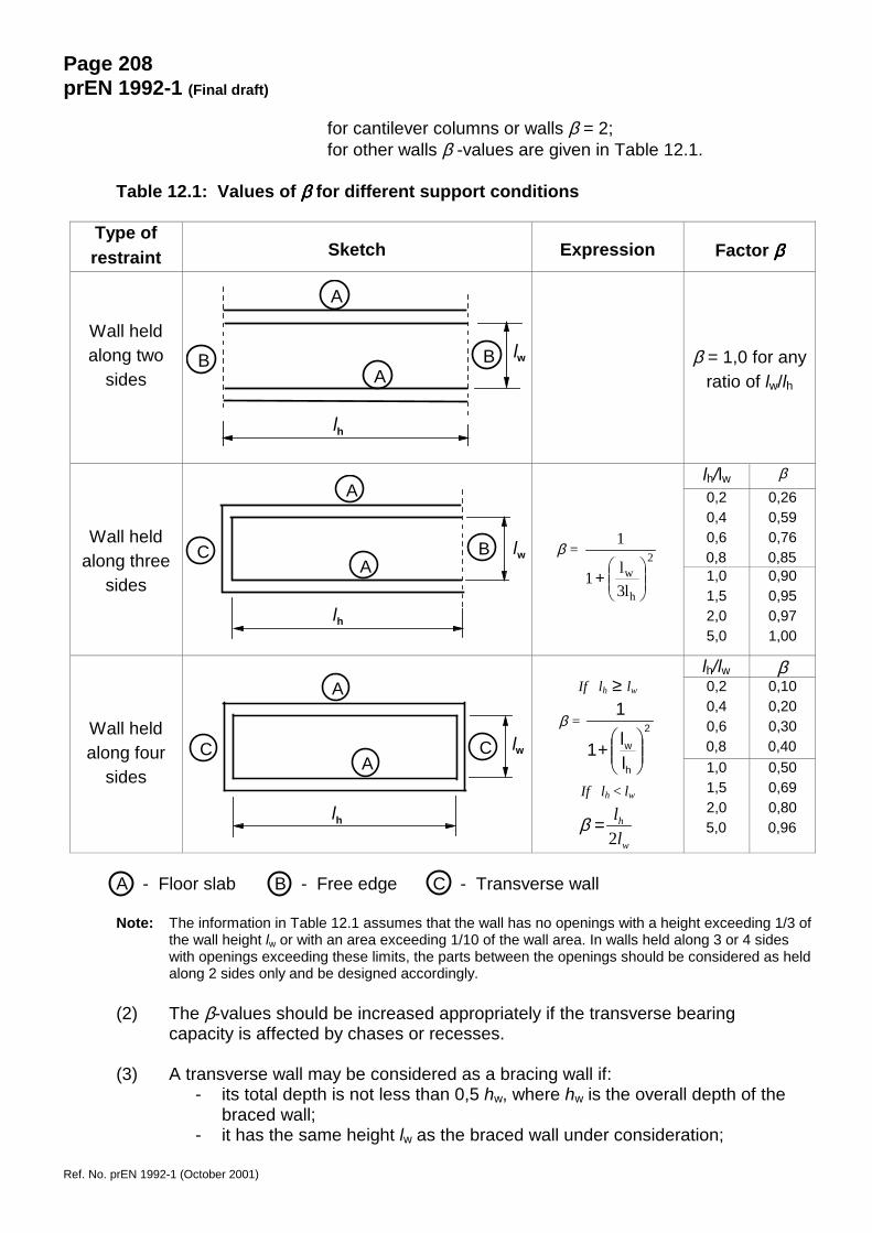
Page 208prEN 1992-1 (Final draft)
Ref. No. prEN 1992-1 (October 2001)
for cantilever columns or walls β = 2;for other walls β -values are given in Table 12.1.
Table 12.1: Values of ββββ for different support conditions
Type ofrestraint Sketch Expression Factor ββββ
Wall heldalong two
sidesβ = 1,0 for any
ratio of lw/lh
lh/lw β0,20,40,60,8
0,260,590,760,85
Wall heldalong three
sides
β = 2
h
w
l3l1
1
���
����
�+ 1,0
1,52,05,0
0,900,950,971,00
lh/lw β0,20,40,60,8
0,100,200,300,40
Wall heldalong four
sides
If lh ≥ lw
β = 2
h
w
ll1
1
���
����
�+
If lh < lw
β =w
h
ll
2
1,01,52,05,0
0,500,690,800,96
A - Floor slab B - Free edge C - Transverse wall
Note: The information in Table 12.1 assumes that the wall has no openings with a height exceeding 1/3 ofthe wall height lw or with an area exceeding 1/10 of the wall area. In walls held along 3 or 4 sideswith openings exceeding these limits, the parts between the openings should be considered as heldalong 2 sides only and be designed accordingly.
(2) The β-values should be increased appropriately if the transverse bearingcapacity is affected by chases or recesses.
(3) A transverse wall may be considered as a bracing wall if:- its total depth is not less than 0,5 hw, where hw is the overall depth of the
braced wall;- it has the same height lw as the braced wall under consideration;
lwA
lh
A
B B
lh
lwA
A
C B
lh
lwA
A
C C
Page 209prEN 1992-1 (Final draft)
Ref. No. prEN 1992-1 (October 2001)
- its length lht is at least equal to lw / 5, where lw denotes the clear height ofthe braced wall;
- within the length lht the transverse wall has no openings.
(4) In the case of a wall connected along the top and bottom in flexurally rigidmanner by in-situ concrete and reinforcement, so that the edge moments can befully resisted, the values for β given in Table 12.1 may be factored by 0,85.
(5) The slenderness of walls in plain concrete cast in-situ should generally notexceed λ = 86 ( e.g. l0/hw = 25). However, for compression members withl0/hw < 2.5, second order analysis is not necessary.
12.6.5.2 Simplified design method for walls and columns
(1) In the absence of a more rigorous approach, the resisting design axial force NRdof a slender member in plain concrete may be calculated using Expression(12.2) in which the eccentricity, e, includes the additional eccentricity, ea,covering the effects of geometric imperfections and creep. ea may bedetermined as follows:
ea = (C/Ecm)(l0 - 2,5hw) (12.10)
whereC factor which may be taken as 0,33 GPa if more accurate
information is not availablel0 Effective length of member (see Expression (12.9))hw overall depth of the cross-section
12.7 Serviceability limit states
(1) Particular care is needed where stresses due to structural restraint are expectedto occur.
(2) The following measures to ensure adequate serviceability should be considered:
a) with regard to crack formation:
- limitation of concrete tensile stresses to acceptable values;- provision of subsidiary structural reinforcement (surface reinforcement, tying
system where necessary);- provision of joints;- methods of concrete technology (e.g. appropriate concrete composition, curing);- choice of appropriate method of construction.
b) with regard to limitation of deformations:
- a minimum section size (see 12.9 below);- limitation of slenderness in the case of compression members.
(3) Any reinforcement provided in plain concrete members, although not taken intoaccount for load bearing purposes, shall comply with 4.4.1.
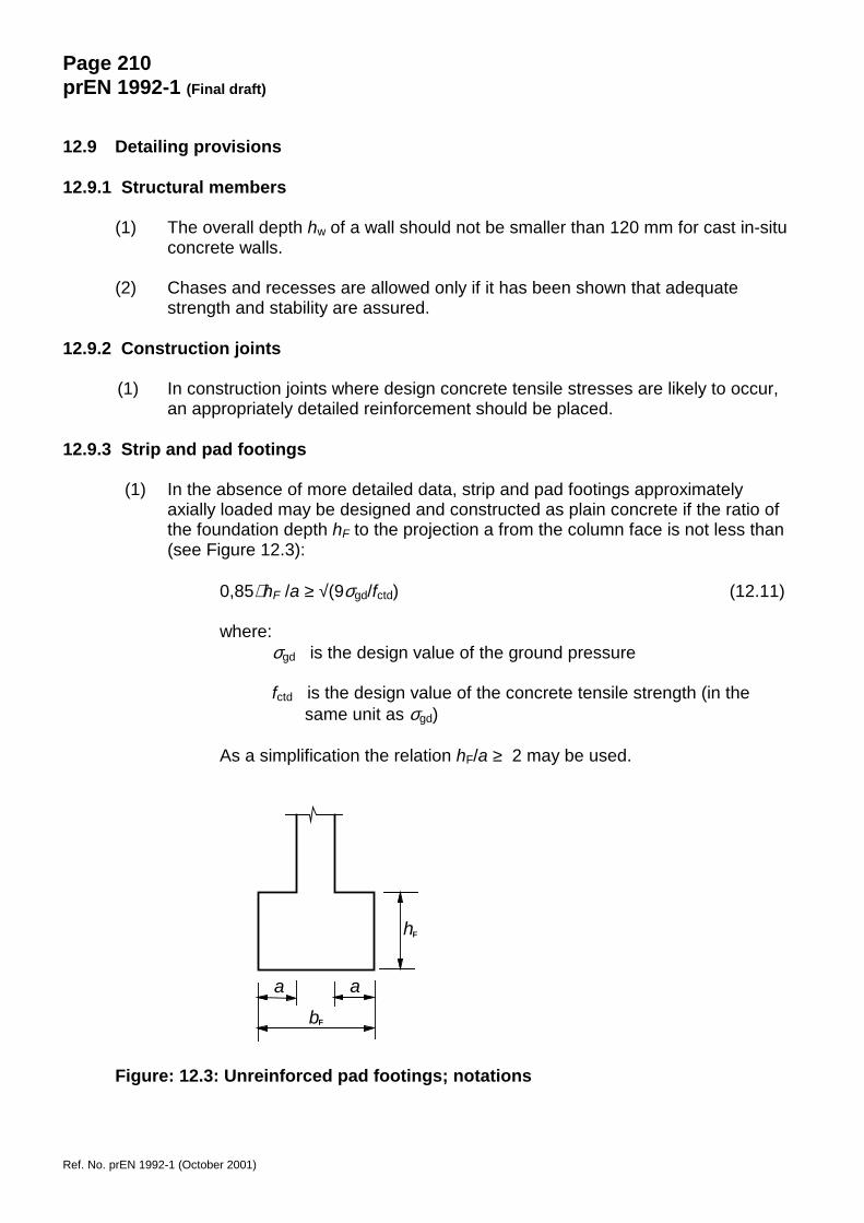
Page 210prEN 1992-1 (Final draft)
Ref. No. prEN 1992-1 (October 2001)
12.9 Detailing provisions
12.9.1 Structural members
(1) The overall depth hw of a wall should not be smaller than 120 mm for cast in-situconcrete walls.
(2) Chases and recesses are allowed only if it has been shown that adequatestrength and stability are assured.
12.9.2 Construction joints
(1) In construction joints where design concrete tensile stresses are likely to occur,an appropriately detailed reinforcement should be placed.
12.9.3 Strip and pad footings
(1) In the absence of more detailed data, strip and pad footings approximatelyaxially loaded may be designed and constructed as plain concrete if the ratio ofthe foundation depth hF to the projection a from the column face is not less than(see Figure 12.3):
0,85⋅ hF /a ≥ √(9σgd/fctd) (12.11)
where:σgd is the design value of the ground pressure
fctd is the design value of the concrete tensile strength (in thesame unit as σgd)
As a simplification the relation hF/a ≥ 2 may be used.
Figure: 12.3: Unreinforced pad footings; notations
a a
bF
hF

Page 211prEN 1992-1 (Final draft)
Ref. No. prEN 1992-1 (October 2001)
Annex A (informative)
Modification of partial factors for materials
A.1 General
(1) The partial factors for materials given in Table 2.2 of 2.2.5 correspond togeometric tolerances of Class 1 in ENV 13670-1 Execution of concrete structuresand normal level of workmanship and inspection (e.g. Inspection Class 2 in ENV13670-1).
(2) Recommendations for reduced partial factors for materials are given in thisInformative Annex (see Annex B of EN 1990 Basis of design). More detailed ruleson control procedures may be given in National rules or product standards forprecast elements.
A.2 In-situ concrete structures
A.2.1 Reduction based on quality control and reduced tolerances
(1) If execution is subjected to a quality control system, which ensures thatunfavourable deviations of cross-section dimensions are within the tightenedtolerances given in Table A.1, the partial safety factor for reinforcement may bereduced to
γs = 1,10
(2) Under the condition given in (1), and if the coefficient of variation of the concretestrength is shown not to exceed 10 %, the partial safety factor for concrete may bereduced to:
γc = 1,4
Note: The quality control system is subject to National rules.
Table A.1: Tightened tolerances
Tightened tolerances (mm)h or b (mm) Cross-section dimension
±∆h, ∆b (mm)Position of reinforcement
+∆c (mm)≤ 150 5 5400 10 10
≥ 2500 30 20Note 1: Linear interpolation may be used for intermediate values.Note 2: +∆c refers to the mean value of reinforcing bars or prestressing tendons in
the cross-section or over a width of one metre (e.g. slabs and walls).
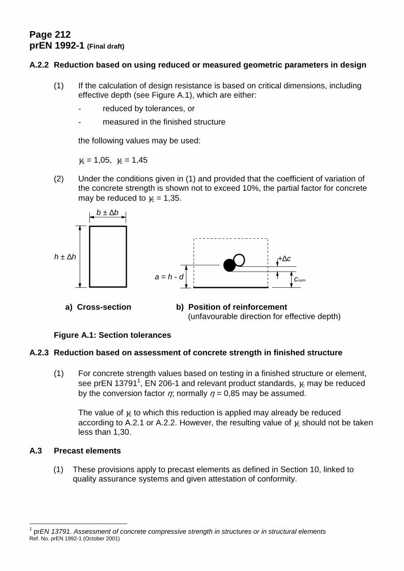
Page 212prEN 1992-1 (Final draft)
Ref. No. prEN 1992-1 (October 2001)
A.2.2 Reduction based on using reduced or measured geometric parameters in design
(1) If the calculation of design resistance is based on critical dimensions, includingeffective depth (see Figure A.1), which are either:- reduced by tolerances, or- measured in the finished structure
the following values may be used:
γs = 1,05, γc = 1,45
(2) Under the conditions given in (1) and provided that the coefficient of variation ofthe concrete strength is shown not to exceed 10%, the partial factor for concretemay be reduced to γc = 1,35.
a) Cross-section b) Position of reinforcement (unfavourable direction for effective depth)
Figure A.1: Section tolerances
A.2.3 Reduction based on assessment of concrete strength in finished structure
(1) For concrete strength values based on testing in a finished structure or element,see prEN 137911, EN 206-1 and relevant product standards, γc may be reducedby the conversion factor η; normally η = 0,85 may be assumed.
The value of γc to which this reduction is applied may already be reducedaccording to A.2.1 or A.2.2. However, the resulting value of γc should not be takenless than 1,30.
A.3 Precast elements
(1) These provisions apply to precast elements as defined in Section 10, linked toquality assurance systems and given attestation of conformity.
1 prEN 13791. Assessment of concrete compressive strength in structures or in structural elements
b ± ∆b
a = h - d
+∆c
cnom
h ± ∆h

Page 213prEN 1992-1 (Final draft)
Ref. No. prEN 1992-1 (October 2001)
A.3.1 Partial factors for actions
(1) For elements in transient design situations, the following partial safety factors maybe applied at the ultimate limit states:
γG = 1,15 = γQ = 1,15
However, actions due to crane lifting and to the adhesion of the concrete to theformwork need to be considered.
(2) For loading conditions other than transient, the coefficient γG relative to the self-weight of the structural elements might be reduced, according to possibleallowances given in EN 1990, Sections 4.1.2 (3) and 6.4.3.2.
A.3.2 Partial factors for materials
(1) Reduced values of γc and γs may be used, if justified by adequate controlprocedures and endorsed by relevant documents, such as the specific productstandards. The tables below indicate amounts and conditions of possiblereductions.
Table A.2: Partial factors for concrete
Reduced γγγγc Specific conditions
γc ⋅ 1
( ≥ 1,50)
- the relevant dimensions comply with 4.3.1.1 of EN 13369 “Commonrules for precast concrete products”;
- the potential strength of concrete complies with 4.2.2 of EN 13369
γc ⋅ 0,93
( ≥ 1,40)
- the relevant dimensions comply with 4.3.1.1 of EN 13369 and the actualcross-section dimensions do not deviate more than 4% (≤ 10 mm) fromthe specified dimensions, or the actual tolerances are included in thecalculation;
- the potential strength of concrete complies with 4.2.2 of EN 13369, withcoefficient of variation ≤ 0,10;
- the demonstration of compliance (see 6.1.1 of EN 13369) is applied onboth the above requirements and assessed by a third party (see 6.1.2.1of EN 13369).
γc ⋅ 0,87
( ≥ 1,30)
as above, plus- the concrete strength derived from tests on cores extracted from the
finished product complies with 4.2.2 of EN 13369, with coefficient ofvariation ≤ 0,15.
Note: γc is the value assumed for the partial safety factor of concrete, as defined for the persistent andtransient design situation in Table 2.4 .
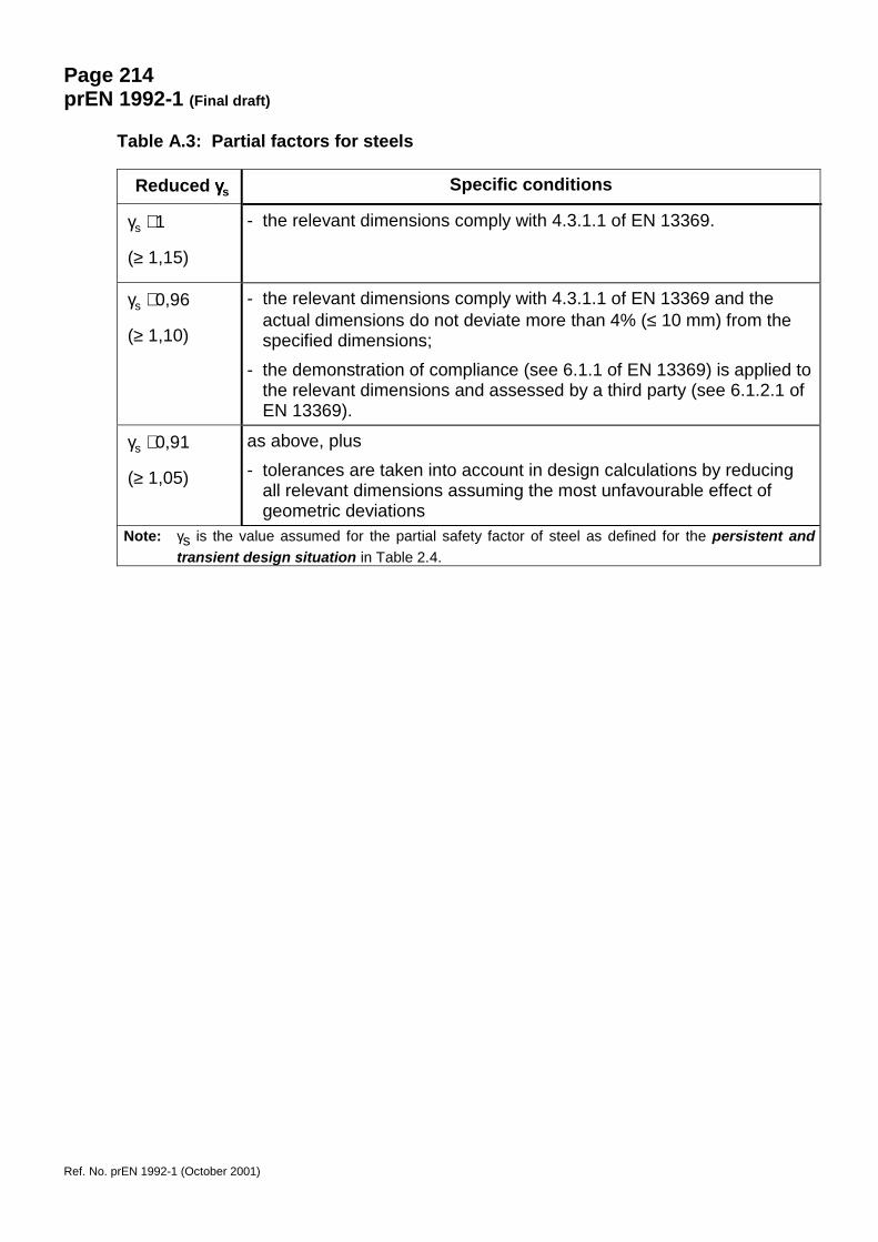
Page 214prEN 1992-1 (Final draft)
Ref. No. prEN 1992-1 (October 2001)
Table A.3: Partial factors for steels
Reduced γγγγs Specific conditions
γs ⋅ 1
(≥ 1,15)
- the relevant dimensions comply with 4.3.1.1 of EN 13369.
γs ⋅ 0,96
(≥ 1,10)
- the relevant dimensions comply with 4.3.1.1 of EN 13369 and theactual dimensions do not deviate more than 4% (≤ 10 mm) from thespecified dimensions;
- the demonstration of compliance (see 6.1.1 of EN 13369) is applied tothe relevant dimensions and assessed by a third party (see 6.1.2.1 ofEN 13369).
γs ⋅ 0,91
(≥ 1,05)
as above, plus- tolerances are taken into account in design calculations by reducing
all relevant dimensions assuming the most unfavourable effect ofgeometric deviations
Note: γs is the value assumed for the partial safety factor of steel as defined for the persistent andtransient design situation in Table 2.4.

Page 215prEN 1992-1 (Final draft)
Ref. No. prEN 1992-1 (October 2001)
ANNEX B (Informative)
Creep and shrinkage
B.1 Basic equations for determining the creep coefficient
(1) The creep coefficient ϕ(t,t0) may be calculated from:
ϕ (t,t0) = ϕ0 · βc(t-t0) (B.1)
where:ϕ0 is the notional creep coefficient and may be estimated from:
ϕ0 = ϕRH · β(fcm) · β(t0) (B.2)
ϕRH is a factor to allow for the effect of relative humidity on the notional creepcoefficient:
3010
10011h⋅
−+=,
/RHRHϕ for fcm ≤ 35 MPa (B.3a)
213010
10011 ααϕ ⋅���
�
���
�⋅
⋅−+=
h,/RH
RH for fcm > 35 MPa (B.3b)
RH is the relative humidity of the ambient environment in %
β (fcm) is a factor to allow for the effect of concrete strength on the notional creepcoefficient:
( )cm
cm8,16f
f =β (B.4)
fcm is the mean compressive strength of concrete in N/mm2 at the age of 28days
β (t0) is a factor to allow for the effect of concrete age at loading on the notionalcreep coefficient:
( ))1,0(
120,0
00 tt
+=β (B.5)
h0 is the notional size of the member in mm where:
uAh c
02= (B.6)
Ac is the cross-sectional area

Page 216prEN 1992-1 (Final draft)
Ref. No. prEN 1992-1 (October 2001)
u is the perimeter of the member in contact with the atmosphere
βc is a coefficient to describe the development of creep with time after loading,and may be estimated using the following Expression:
( ) ( )( )
3,0
0H
00c �
�
���
�
−+−=−
tttttt
ββ (B.7)
t is the age of concrete in days at the moment considered
t0 is the age of concrete at loading in days
t � t0 is the non-adjusted duration of loading in days
βH is a coefficient depending on the relative humidity (RH in %) and thenotional member size (h0 in mm). It may be estimated from:
βH =1,5 [1 + (0,012 RH)18] h0 + 250 ≤ 1500 for fcm ≤ 35 (B.8a)
βH =1,5 [1 + (0,012 RH)18] h0 + 250 α3 ≤ 1500 α3 for fcm ≥ 35 (B.8b)
α1/2/3 are coefficients to consider the influence of the concrete strength:
7,0
cm1
35��
���
�=f
α2,0
cm2
35��
���
�=f
α5,0
cm3
35��
���
�=f
α (B.8c)
(2) The effect of type of cement on the creep coefficient of concrete may be taken intoaccount by modifying the age of loading t0 in Expression (B.5) according to the followingExpression:
5,012
92,1
T0,T0,0 ≥
��
�
�
��
�
�+
+⋅=
α
ttt (B.9)
where:t0,T is the temperature adjusted age of concrete at loading in days adjusted
according to Expression (B.10)α is a power which depends on type of cement:
α = -1 for slowly hardening cements, Sα = 0 for normal or rapid hardening cements, Nα = 1 for rapid hardening high strength cements, R
(3) The effect of elevated or reduced temperatures within the range 0 � 80°C on the maturityof concrete may be taken into account by adjusting the concrete age according to thefollowing Expression:
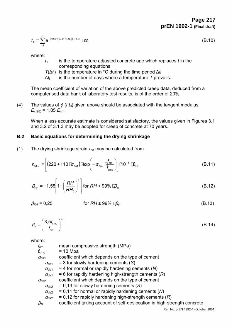
Page 217prEN 1992-1 (Final draft)
Ref. No. prEN 1992-1 (October 2001)
�=
−+− ⋅=n
ii
),)](/[(T
ie1
65132734000 tt tT ∆∆ (B.10)
where:tT is the temperature adjusted concrete age which replaces t in the
corresponding equationsT(∆ti) is the temperature in °C during the time period ∆ti∆ti is the number of days where a temperature T prevails.
The mean coefficient of variation of the above predicted creep data, deduced from acomputerised data bank of laboratory test results, is of the order of 20%.
(4) The values of ϕ (t,t0) given above should be associated with the tangent modulusEc(28) = 1,05 Ecm
When a less accurate estimate is considered satisfactory, the values given in Figures 3.1and 3.2 of 3.1.3 may be adopted for creep of concrete at 70 years.
B.2 Basic equations for determining the drying shrinkage
(1) The drying shrinkage strain εcd may be calculated from
( ) RH6
cmo
cmds2ds1cd, 10exp110220 β
ff
⋅⋅��
���
����
�
�⋅−⋅⋅+= −
∞ ααε (B.11)
sl
3
0RH 99%for11,55 ββ ⋅<
��
�
�
��
�
�
���
�
�−−= RHRHRH (B.12)
βRH = 0,25 for RH ≥ 99% ⋅ βsl (B.13)
0.1
cm
cmosl
3,5���
�
�=
ffβ (B.14)
where:fcm mean compressive strength (MPa)fcmo = 10 Mpaαds1 coefficient which depends on the type of cement
αds1 = 3 for slowly hardening cements (S)αds1 = 4 for normal or rapidly hardening cements (N)αds1 = 6 for rapidly hardening high-strength cements (R)
αds2 coefficient which depends on the type of cementαds2 = 0,13 for slowly hardening cements (S)αds2 = 0,11 for normal or rapidly hardening cements (N)αds2 = 0,12 for rapidly hardening high-strength cements (R)
βsl coefficient taking account of self-desiccation in high-strength concrete

Page 218prEN 1992-1 (Final draft)
Ref. No. prEN 1992-1 (October 2001)
RH ambient relative humidity (%)RH0 = 100%t age of concrete (days)t1 = 1 dayh = 2 Ac/u notional size of member (mm),
where Ac is the cross-section (mm2) and u is the perimeter of the member incontact with the atmosphere (mm)
h0 = 100 mm.
(2) For concrete strengths fck ≤ 50 MPa swelling should be expected if the concrete isexposed to RH ≥ 99%.
(3) For concrete strengths fck > 50 MPa swelling will occur at lower relative humiditiesbecause of the preceding reduction of the internal relative humidity due to self-desiccation of the concrete.

Page 219prEN 1992-1 (Final draft)
Ref. No. prEN 1992-1 (September 2001)
Annex C (Informative)
Indicative strength classes for durability
(1) The choice of adequately durable concrete for corrosion protection of reinforcement andprotection of concrete attack, requires consideration of the composition of concrete. Thismay result in a higher compressive strength of the concrete than required for structuraldesign. Indicative strength classes relating to the environmental classes, defined inTable 4.1, are given in Table C.1.
(2) When the chosen strength is higher than that required for structural design the value offct,m should be associated with the higher strength in the calculation of minimumreinforcement according to 7.3.2 and 9.1.1.1 and crack width control according to 7.3.3and 7.3.4.
Table C.1: Indicative strength classes
Exposure Classes according to Table 4.1
CorrosionCarbonation-induced corrosion Chloride-induced
corrosionChloride-inducedcorrosion from sea-water
XC1 XC2 XC3 XC4 XD1 XD2 XD3 XS1 XS2 XS3Indicative Strength
Class C20/25 C25/30 C30/37 C30/37 C35/45 C30/37 C35/45
Damage to ConcreteNo risk Freeze/Thaw Attack Chemical Attack
X0 XF1 XF2 XF3 XA1 XA2 XA3Indicative Strength
ClassC12/15 C30/37 C25/30 C30/37 C30/37 C35/45
Note: The values given in Table C.1 are generally a lower bound and the actual value will depend on the cementtype and concrete mix design (e.g. CEM1 42.5 or 52.5 (see EN 197) may give higher values).
.
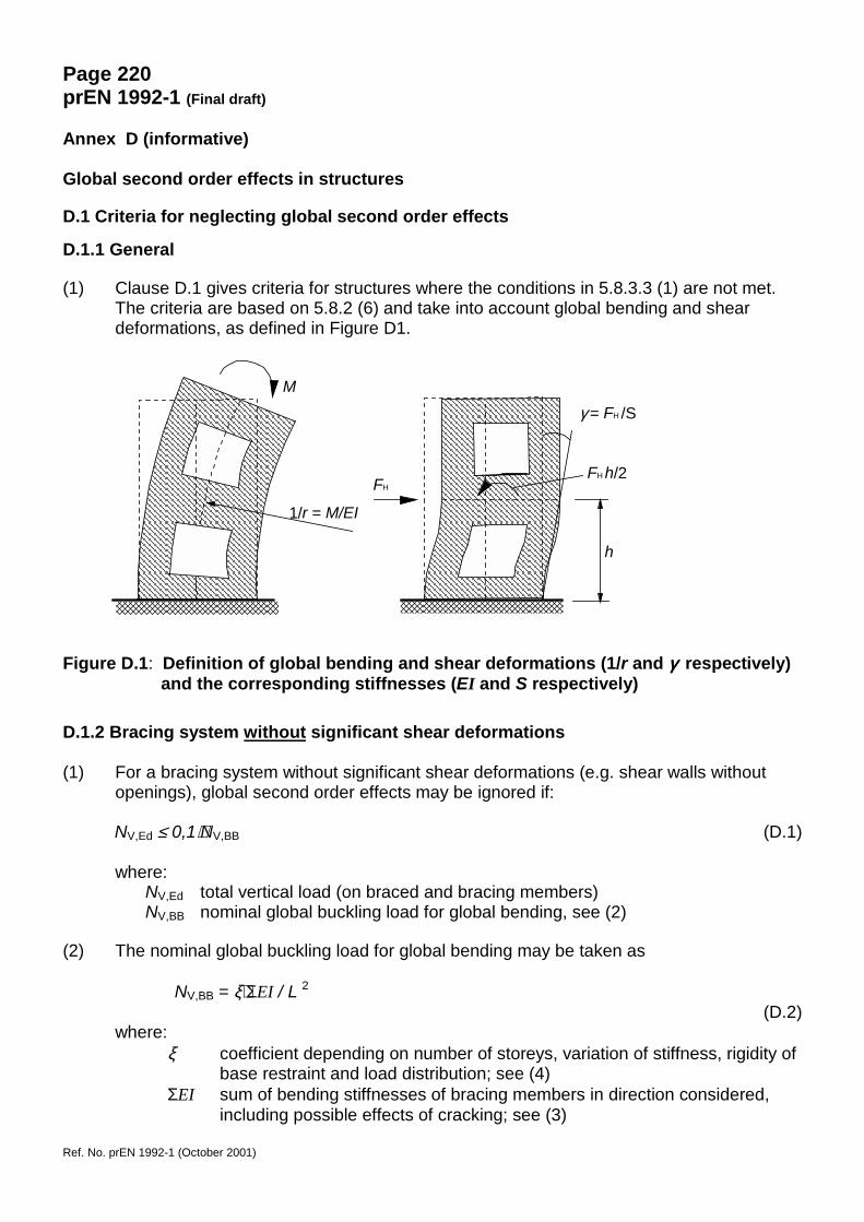
Page 220prEN 1992-1 (Final draft)
Ref. No. prEN 1992-1 (October 2001)
Annex D (informative)
Global second order effects in structures
D.1 Criteria for neglecting global second order effects
D.1.1 General
(1) Clause D.1 gives criteria for structures where the conditions in 5.8.3.3 (1) are not met.The criteria are based on 5.8.2 (6) and take into account global bending and sheardeformations, as defined in Figure D1.
Figure D.1: Definition of global bending and shear deformations (1/r and γγγγ respectively)and the corresponding stiffnesses (EI and S respectively)
D.1.2 Bracing system without significant shear deformations
(1) For a bracing system without significant shear deformations (e.g. shear walls withoutopenings), global second order effects may be ignored if:
NV,Ed ≤ 0,1⋅NV,BB (D.1)
where:NV,Ed total vertical load (on braced and bracing members)NV,BB nominal global buckling load for global bending, see (2)
(2) The nominal global buckling load for global bending may be taken as
NV,BB = ξ⋅ΣEI / L 2(D.2)
where:ξ coefficient depending on number of storeys, variation of stiffness, rigidity of
base restraint and load distribution; see (4)ΣEI sum of bending stiffnesses of bracing members in direction considered,
including possible effects of cracking; see (3)
M
1/r = M/EI
FHFH h/2
γ = FH /S
h
Page 221prEN 1992-1 (Final draft)
Ref. No. prEN 1992-1 (October 2001)
L total height of building above level of moment restraint.
(3) In the absence of a more accurate evaluation of the stiffness, the following may be usedfor a bracing member with cracked section:
EI ≈ 0,4 EcdIc (D.3)
where:Ecd = Ecm/1,2, design value of concrete modulus, see 5.8.6 (3)Ic second moment of area of bracing member
If the cross-section is shown to be uncracked in the ultimate limit state, constant 0,4 inExpression (D.3) may be replaced by 0,8.
(4) If bracing members have constant stiffness along the height and the total vertical loadincreases with the same amount per storey, then ξ may be taken as
k7,01
16,1n
n8,7s
s⋅+
⋅+
⋅=ξ (D.4)
where:ns number of storeysk relative flexibility of moment restraint; see (5).
(5) The relative flexibility of moment restraint at the base is defined as:
k = (θ/M)⋅(EI/L) (D.5)
where:θ rotation for bending moment MEI stiffness according to (3)L total height of bracing unit
Note: For k = 0, i.e. rigid restraint, Expressions (D.1)-(D.4) can be combined into Expression (5.24),where coefficient follows from 0,1⋅(0,4/1,2)⋅7,8 = 0,26.
.
D.1.3 Bracing system with significant global shear deformations
(1) Global second order effects may be ignored if the following condition is fulfilled:
BS,VBB,V
BB,VB,VEd,V /1
1,01,0FF
FFF
+⋅=⋅≤
(D.6)where
FV,B global buckling load taking into account global bending and shearFV,BB global buckling load for pure bending, see D.1.2 (2)FV,BS global buckling load for pure shear, FV,BS = ΣSΣS total shear stiffness of bracing units (see Figure D1)
Page 222prEN 1992-1 (Final draft)
Ref. No. prEN 1992-1 (October 2001)
Note: The global shear deformation of a bracing unit is normally governed mainly by local bendingdeformations (Figure D.1). Therefore, in the absence of a more refined analysis, cracking maybe taken into account for S in the same way as for EI; see D.1.2 (3).
D.2 Methods for calculation of global second order effects
(1) This clause is based on linear second order analysis according to 5.8.7. Global secondorder effects may then be taken into account by analysing the structure for fictitious,magnified horizontal forces FH,Ed:
V,BV,Ed
0Ed,HH,Ed /1 FF
FF
−= (D.7)
where:FH,0Ed first order horizontal force due to wind, imperfections etc.FV,Ed total vertical load on bracing and braced membersFV,B nominal global buckling load, see (2).
(2) The buckling load FV,B may be determined according to D.1.3 (or D.1.2 if global sheardeformations are negligible). However, in this case nominal stiffness values according to5.8.7.2 should be used, including the effect of creep.
(3) In cases where the global buckling load FV,B is not defined, the following expression maybe used instead:
H,0EdH,1Ed
H,0EdH,Ed /1 FF
FF
−= (D.8)
where:FH,1Ed fictitious horizontal force, giving the same bending moments as vertical
load NV,Ed acting on the deformed structure, with deformation caused byFH,0Ed (first order deformation), and calculated with nominal stiffness valuesaccording to 5.8.7.2
Note: Expression (D.8) follows from a step-by step numerical calculation, where the effect of vertical loadand deformation increments, expressed as equivalent horizontal forces, are added in consecutivesteps. The increments will form a geometric series after a few steps. Assuming this occurs even atthe first step, which is analogous to assuming β=1 in 5.8.7.3 (3), the sum can be expressed as inExpression (D.8). This assumption requires that the stiffness values representing the final stage ofdeformations are used in all steps (note that this is also the basic assumption behind the analysisbased on nominal stiffness values).
In other cases, e.g. if uncracked sections are assumed in the first step and cracking is found tooccur in later steps, or if the distribution of equivalent horizontal forces changes significantlybetween the first steps, then more steps have to be included in the analysis, until the assumptionof a geometric series is met. Example with two more steps than in Expression (D.8):
FH,Ed = FH,0Ed + FH,1Ed + FH,2Ed /(1- FH,3Ed / FH,2Ed)
Page 223prEN 1992-1 (Final draft)
Ref. No. prEN 1992-1 (October 2001)
Annex E (Informative)
Soil structure interaction
E.1 Shallow foundations
E.1.1 General
(1) As a consequence of the interaction between the ground, the foundation and thesuperstructure, modelling of the contact pressure distribution requires consideration ofthe actions that the columns transmit to the foundation, which are themselves dependenton the relative settlements.
(2) In general the problem is solved by ensuring that the displacements and associatedreactions of the soil and the structure are compatible.
(3) Although the above general procedure is adequate, many uncertainties still exist, due tothe load sequence and creep effects. For this reason different levels of analysis,depending on the degree of idealisation of the mechanical models, are usually defined.
(4) If the superstructure is considered as flexible, then the transmitted loads do not dependon the relative settlements, because the structure has no rigidity. In this case the loadsare no longer unknown, and the problem is reduced to the analysis of a foundation on adeforming ground.
(5) If the superstructure is considered as rigid, then the unknown foundation loads can beobtained by the condition that settlements must lie on a plane. It must be checked thatthe rigidity exists until the ultimate limit state is reached.
(6) A further simplifying scheme arises if the foundation system can be assumed to be rigidor the supporting ground is very stiff. In both cases, the loads transmitted from thesuperstructure are not modified as the relative settlements can be ignored.
(7) To determine the approximate rigidity of the structural system, an analysis may be madecomparing the combined stiffness of the foundation, superstructure framing membersand shear walls, with the stiffness of the ground. This relative stiffness KR will determinewhether the foundation or the structural system should be considered rigid or flexible.The following expression can be used for building structures:
KR = (EJ)S / (El 3) (E.1)
where:
(EJ)S approximate value of the flexural rigidity per unit width of the buildingstructure under consideration, obtained by summing the flexural rigidity of thefoundation, of each framed member and any shear wall
E deformation modulus of the groundl length of the foundation
Relative stiffnesses higher than 0,5 indicate rigid structural systems.
Page 224prEN 1992-1 (Final draft)
Ref. No. prEN 1992-1 (October 2001)
E.1.2 Levels of analysis
(1) For design purposes, the following levels of analysis are permitted:
Level 0: In this level, linear distribution of the contact pressure may be assumed.
The following preconditions should be fulfilled:- the contact pressure does not exceed the design values for both the serviceability
and the ultimate limit states;- at the serviceability limit state, the structural system is not affected by
settlements, or the expected differential settlements are not significant;- at the ultimate limit state, the structural system has sufficient plastic deformation
capacity so that differences in settlements do not affect the design.
Level 1: The contact pressure may be determined taking into account the relativestiffness of the foundation and the soil and the resulting deformations evaluated to checkthat they are within acceptable limits.
The following preconditions should be fulfilled:
- sufficient experience exists to show that the serviceability of the superstructure isnot likely to be affected by the resulting soil deformation;
- at the ultimate limit state, the structural system has adequate ductile behaviour.
Level 2: At this level of analysis the influence of ground deformations on thesuperstructure is considered. The structure is analysed under the imposed deformationof the foundation to determine the adjustments to the loads applied to the foundations. If the resulting adjustments are significant (i.e. > �10� % ) then Level 3 analysis shouldbe adopted.
Level 3: This is a complete interactive procedure taking into account the overallstructural system.
E.2 Piled foundations
(1) If the pile cap is rigid, a linear variation of the settlements of the individual piles may beassumed which depends on the rotation of the pile cap. If this rotation is zero or may beignored, equal settlement of all piles may be assumed. From equilibrium equations, theunknown pile loads and the settlement of the group can be calculated.
(2) However, when dealing with a piled raft, interaction occurs not only between individual pilesbut also between the raft and the piles, and no simple approach to analyse this problem isavailable.
(3) The response of a pile group to horizontal loads generally involves not only the lateralstiffness of the surrounding soil and of the piles, but also their axial stiffness (e.g. lateralload on a pile group causes tension and compression on edge piles).
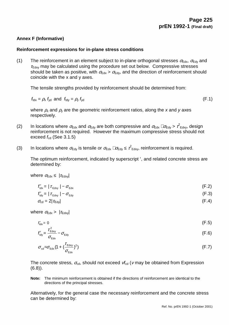
Page 225prEN 1992-1 (Final draft)
Ref. No. prEN 1992-1 (October 2001)
Annex F (Informative)
Reinforcement expressions for in-plane stress conditions
(1) The reinforcement in an element subject to in-plane orthogonal stresses σEdx, σEdy andτEdxy may be calculated using the procedure set out below. Compressive stressesshould be taken as positive, with σEdx > σEdy, and the direction of reinforcement shouldcoincide with the x and y axes.
The tensile strengths provided by reinforcement should be determined from:
ftdx = ρx fyd and ftdy = ρy fyd (F.1)
where ρx and ρy are the geometric reinforcement ratios, along the x and y axesrespectively.
(2) In locations where σEdx and σEdy are both compressive and σEdx ⋅ σEdy > τ2Edxy, design
reinforcement is not required. However the maximum compressive stress should notexceed fcd (See 3.1.5)
(3) In locations where σEdy is tensile or σEdx ⋅ σEdy ≤ τ2Edxy, reinforcement is required.
The optimum reinforcement, indicated by superscript ′, and related concrete stress aredetermined by:
where σEdx ≤ |τEdxy|
EdxEdxytdx || στ −=′f (F.2)
EdyEdxytdy || στ −=′f (F.3)σcd = 2|τEdy| (F.4)
where σEdx > |τEdxy|
0tdx =′f (F.5)
EdyEdx
2Edxy
tdy σστ
−=′f (F.6)
))(1( 2
Edx
EdxyEdxcd σ
τσσ += (F.7)
The concrete stress, σcd, should not exceed νfcd (ν may be obtained from Expression(6.8)).
Note: The minimum reinforcement is obtained if the directions of reinforcement are identical to thedirections of the principal stresses.
Alternatively, for the general case the necessary reinforcement and the concrete stresscan be determined by:
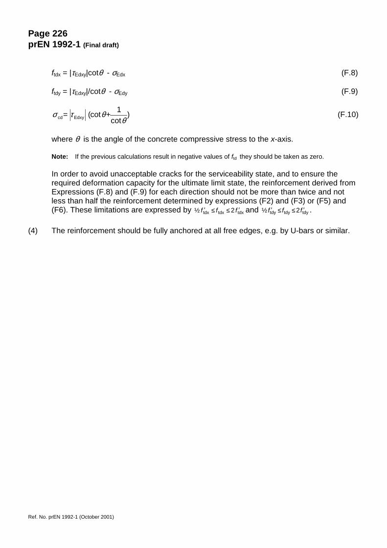
Page 226prEN 1992-1 (Final draft)
Ref. No. prEN 1992-1 (October 2001)
ftdx = |τEdxy|cotθ - σEdx (F.8)
ftdy = |τEdxy|/cotθ - σEdy (F.9)
)cot
1cot(Edxycd θθτσ += (F.10)
where θ is the angle of the concrete compressive stress to the x-axis.
Note: If the previous calculations result in negative values of ftd they should be taken as zero.
In order to avoid unacceptable cracks for the serviceability state, and to ensure therequired deformation capacity for the ultimate limit state, the reinforcement derived fromExpressions (F.8) and (F.9) for each direction should not be more than twice and notless than half the reinforcement determined by expressions (F2) and (F3) or (F5) and(F6). These limitations are expressed by tdxtdxtdx 2½ fff ′≤≤′ and tdytdytdy 2½ fff ′≤≤′ .
(4) The reinforcement should be fully anchored at all free edges, e.g. by U-bars or similar.
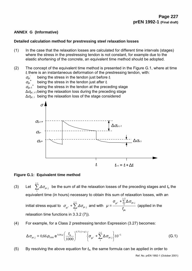
Page 227prEN 1992-1 (Final draft)
Ref. No. prEN 1992-1 (October 2001)
ANNEX G (Informative)
Detailed calculation method for prestressing steel relaxation losses
(1) In the case that the relaxation losses are calculated for different time intervals (stages)where the stress in the prestressing tendon is not constant, for example due to theelastic shortening of the concrete, an equivalent time method should be adopted.
(2) The concept of the equivalent time method is presented in the Figure G.1, where at timeti there is an instantaneous deformation of the prestressing tendon, with:σpi
- being the stress in the tendon just before tiσpi
+ being the stress in the tendon just after tiσpi-1
+ being the stress in the tendon at the preceding stage∆σpr, i-1being the relaxation loss during the preceding stage∆σpr, i being the relaxation loss of the stage considered
Figure G.1: Equivalent time method
(3) Let �−1
1
i
j,prσ∆ be the sum of all the relaxation losses of the preceding stages and te the
equivalent time (in hours) necessary to obtain this sum of relaxation losses, with an
initial stress equal to �−
++
1
1
i
j,prpi σ∆σ and with pk
1i
1jpr,pi ∆
f
σσµ
�+=
−+
(applied in the
relaxation time functions in 3.3.2 (7)).
(4) For example, for a Class 2 prestressing tendon Expression (3.27) becomes:
51
1
1750099
1000 101000
660 −−−
���
��� +�
�
�
�= �+
i
j,prpi
)(,e,
jpr, ∆e,∆ σσtρσµ
µ (G.1)
(5) By resolving the above equation for te, the same formula can be applied in order to
σ
ti
σpi-
σpi+
σpi-1+∆σpr,i-1
∆σpr,i
ti+1 = ti + ∆ti
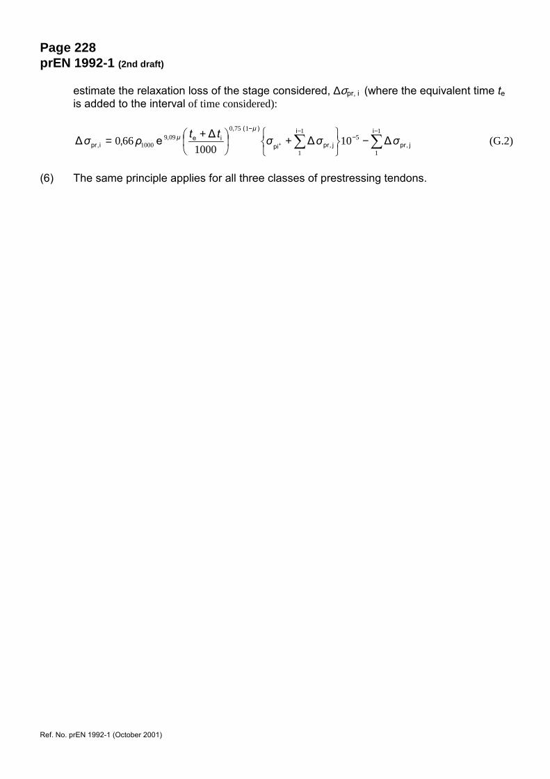
Page 228prEN 1992-1 (2nd draft)
Ref. No. prEN 1992-1 (October 2001)
estimate the relaxation loss of the stage considered, ∆σpr, i (where the equivalent time teis added to the interval of time considered):
��−
−−−
−���
��� +�
�
�
� += +
1
1
51
1
1750099
1000 101000
660i
j,pr
i
j,prpi
)(,ie,
i,pr ∆∆∆e,∆ σσσttρσµ
µ (G.2)
(6) The same principle applies for all three classes of prestressing tendons.
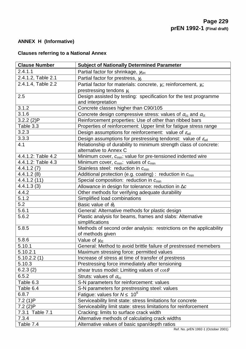
Page 229prEN 1992-1 (Final draft)
Ref. No. prEN 1992-1 (October 2001)
ANNEX H (Informative)
Clauses referring to a National Annex
Clause Number Subject of Nationally Determined Parameter2.4.1.1 Partial factor for shrinkage, γSH2.4.1.2, Table 2.1 Partial factor for prestress, γp2.4.1.4, Table 2.2 Partial factor for materials: concrete, γc; reinforcement, γs;
prestressing tendons γs2.5 Design assisted by testing: specification for the test programme
and interpretation3.1.2 Concrete classes higher than C90/1053.1.6 Concrete design compressive stress: values of αcc and αct3.2.2 (2)P Reinforcement properties: Use of other than ribbed barsTable 3.3 Properties of reinforcement: Upper limit for fatigue stress range3.2.3 Design assumptions for reinforcement: value of εud3.3.3 Design assumptions for prestressing tendonst: value of εud4.1 Relationship of durability to minimum strength class of concrete:
alternative to Annex C4.4.1.2: Table 4.2 Minimum cover, cmin: value for pre-tensioned indented wire4.4.1.2: Table 4.3 Minimum cover, cmin: values of cmin4.4.1.2 (7) Stainless steel: reduction in cmin4.4.1.2 (8) Additional protection (e.g. coating) : reduction in cmin4.4.1.2 (11) Special composition: reduction in cmin4.4.1.3 (3) Allowance in design for tolerance: reduction in ∆c4.4.2 Other methods for verifying adequate durability5.1.2 Simplified load combinations5.2 Basic value of θ05.6.1 General: Alternative methods for plastic design5.6.2 Plastic analysis for beams, frames and slabs: Alternative
simplifications5.8.5 Methods of second order analysis: restrictions on the applicability
of methods given5.8.6 Value of γcE5.10.1 General: Method to avoid brittle failure of prestressed memebers5.10.2.1 Maximum stressing force: permitted values5.10.2.2 (1) Increase of stress at time of transfer of prestress5.10.3 Prestressing force immediately after tensioning6.2.3 (2) shear truss model: Limiting values of cotθ6.5.2 Struts: values of αccTable 6.3 S-N parameters for reinforcement: valuesTable 6.4 S-N parameters for prestressing steel: values6.8.7 Fatigue: values for N ≤ 106
7.2 (1)P Serviceability limit state: stress limitations for concrete7.2 (2)P Serviceability limit state: stress limitations for reinforcement7.3.1 Table 7.1 Cracking: limits to surface crack width7.3.4 Alternative methods of calculating crack widthsTable 7.4 Alternative values of basic span/depth ratios

Page 230prEN 1992-1 (2nd draft)
Ref. No. prEN 1992-1 (October 2001)
7.4.3 Alternative methods of calculating deflectionsTable 8.1 Minimum mandrel sizes for Class C reinforcement8.4.1 Required tests for mechanical anchoring devices8.6: Expression (8.7) Anchorage capacity of a welded bar8.8 Additional rules for large diameter bars: limiting bar size8.10.2.1 Transfer of prestress: values of ηp1 for types of tendons other than
indented wires and 7-wire strands8.10.2.2 Anchorage of tensile force for the ultimate limit state: values of ηp2
for types of tendons other than indented wires and 7-wire strands9.1 General: all minimum and maximum values for reinforcement areas9.2.1.1 Beams: - minimum reinforcement area,
- maximum reinforcement area, - bending moment at support in monolithic construction - %
of maximum bending moment in the span,9.2.1.2 Beams: Other detailing arrangements: bending moment at support
in monolithic construction: % maximum bending moment in theSpan
9.2.1.4 Anchorage of bottom reinforcement at an end support: area of steelprovided over supports with little or no end fixity in design
9.2.2 Shear reinforcement:- minimum % of shear reinforcement in the form of links- minimum shear reinforcement- maximum longitudinal spacing of links- maximum longitudinal spacing of bent up bars- maximum transverse spacing of links
9.2.3 Minimum torsion reinforcement9.2.4 Minimum surface reinforcement9.5.1 Columns: longitudinal reinforcement
- minimum diameter- minimum area- maximum area
9.5.2 Columns: maximum spacing of transverse reinforcement9.6.2 Walls: Minimum area of vertical reinforcement9.6.3 Walls: Minimum area of horizontal reinforcement9.7 Deep beams: minimum area of reinforcement
- minimum area of distribution reinforcement9.8.5 Bored Piles: detailing rules9.10.2.3 Horizontal ties to columns and/or walls11.3.1.5 Values of αlcc, αlct 11.6 Value of γc for lightweight aggregate concrete12.2.1 Values of αcc, αctInformative Annex A Modification of partial factors for materialsInformative Annex B Creep and shrinkageInformative Annex C Indicative strength classes for durabilityInformative Annex D Global second order effects in structuresInformative Annex E Soil structure interactionInformative Annex F Reinforcement expressions for in-plane stress conditionsInformative Annex G Detailed calculation method for prestressing steel relaxation losses