Detailing Print
207
Pro-Engineer DETAILING 1/ 207 Detailing Detailing lets you create and manipulate detailed engineering drawings that use your 3D model as a geometry source. With Detailing, you can pass dimensions, notes, and other elements of design between the model and its views on the plotted sheet. Use the Detailing area of Help to learn about creating drawings directly from the solid model, customizing the drawings with sketched geometry, and making cosmetic changes to the drawings. Detailing Help shows you how to manipulate items in a drawing, annotate your drawings, and add different kinds of textual and symbolic information. You will learn how to create views and custom formats and how to use logic statements to control the look of the drawing. Detailing Modules Detailing Home Detailing in Pro/E Wildfire lets you pass the dimensions, notes, GTOLs and other detailing items from the 3D model directly to views on the plotted sheet. Use these instructions to prepare drawings of parts and assemblies that pass information forward and backward in the design workflow. Common Detailing Topics Detail Overview Basic Pro/E Drawing Mode and Pro/Detail optional module, general overview. Inserting Views Associating 3D parts with drawing files and adding drawing views to the sheet. Applying Dimensions Showing dimensions passed from the 3D model, adding extra dimensions, the Pro/E dimension formats.. Applying Non-Dimension Detailing Adding and editing GTOLs, Datum Targets, surface finish symbols, BOM Balloons and other conventional detail items. Using 2-D Drafting Creating drafted shapes using smart relational and constraint drawing tools. Tables Using tables, rows, columns and cells. Reports Generating Bills of Materials and other parameter driven associative reports
-
Upload
sathi-mech -
Category
Documents
-
view
100 -
download
3
description
pro e
Transcript of Detailing Print
Pro-Engineer DETAILING 1/ 207
Detailing Detailing lets you create and manipulate detailed engineering drawings that use your 3D model as a geometry source. With Detailing, you can pass dimensions, notes, and other elements of design between the model and its views on the plotted sheet. Use the Detailing area of Help to learn about creating drawings directly from the solid model, customizing the drawings with sketched geometry, and making cosmetic changes to the drawings. Detailing Help shows you how to manipulate items in a drawing, annotate your drawings, and add different kinds of textual and symbolic information. You will learn how to create views and custom formats and how to use logic statements to control the look of the drawing. Detailing Modules
Detailing Home Detailing in Pro/E Wildfire lets you pass the dimensions, notes, GTOLs and other detailing items from the 3D model directly to views on the plotted sheet. Use these instructions to prepare drawings of parts and assemblies that pass information forward and backward in the design workflow. Common Detailing Topics
Detail Overview Basic Pro/E Drawing Mode and Pro/Detail optional module, general overview. Inserting Views Associating 3D parts with drawing files and adding drawing views to the sheet. Applying Dimensions Showing dimensions passed from the 3D model, adding extra dimensions, the Pro/E dimension formats.. Applying Non-Dimension Detailing Adding and editing GTOLs, Datum Targets, surface finish symbols, BOM Balloons and other conventional detail items. Using 2-D Drafting Creating drafted shapes using smart relational and constraint drawing tools. Tables Using tables, rows, columns and cells. Reports Generating Bills of Materials and other parameter driven associative reports
Pro-Engineer DETAILING 2/ 207
The Pro/ENGINEER Drawing Modes Pro/ENGINEER offers functionality for working with engineering drawings in two separate components: Drawing mode and an optional add on module, Pro/DETAIL. Using the Pro/ENGINEER Drawing mode, you can create drawings of all Pro/ENGINEER models, or import drawing files from other systems. You can annotate the drawing with notes, manipulate the dimensions, and use layers to manage the display of different items. All views in the drawing are associative: if you change a dimensional value in one view, the system updates other drawing views accordingly. Moreover, Pro/ENGINEER associates drawings with their parent models- the model automatically reflects any dimensional changes that you make to a drawing. In addition, corresponding drawings also reflect any changes that you make to a model (such as the addition or deletion of features and dimensional changes) in Part, Sheetmetal, Assembly, or Manufacturing modes. Pro/DETAIL Pro/DETAIL, the optional add-on module, extends the drawing capability offered by Pro/ENGINEER. You can use it with basic Pro/ENGINEER or as a standalone module to create, view, and annotate models and drawings. Pro/DETAIL supports additional view types and multisheets, offers numerous commands for manipulating items in a drawing, and lets you add and modify different kinds of textual and symbolic information. In addition, you can use it to customize engineering drawings with sketched geometry, create custom drawing formats, and make multiple cosmetic changes to drawings. With Pro/DETAIL, you can also use a pop-up menu to modify any object in a drawing from anywhere in the menu tree. At any time when a drawing window is active, you can interrupt your current process and activate a drawing object for modification . Drawing Interfaces With a license for Pro/INTERFACE or Pro/DETAIL, you can access various interface commands for exporting drawing files to other systems and importing files into Drawing mode. Selecting Objects in Drawings To perform operations within your drawings you must to select objects. You can use preselection highlighting, drawing object filters, and several selection methods. Preselection Highlighting Preselection highlighting allows you to visually confirm the item that will be selected before you select it. By default, as the pointer passes over an object in the graphics area, the object is highlighted. The object's name is displayed in a tooltip on the drawing and on the status bar in lower left-hand corner of the application. For example, d92: F9(HOLE) displays to indicate that the pointer is over the diameter dimension for the ninth model feature, a hole. Drawing Object Filters You can limit which objects are prehighlighted and, ultimately, what is selectable using the drawing filter. Filters allow you to change the type of entities you can select, which simplifies graphic selection. So, when cleaning up the placement of dimensions, you can set the filter to make only dimensions available for selection. The filter is a drop down list on the right side of the status bar. While an object is designated in the filter, all other object types are disallowed from selection. Methods of Selecting Depending on the type of operation you are completing, you may need to select a specific drawing object, or even multiple object types simultaneously. The following selection methods enable you to efficiently select the objects:
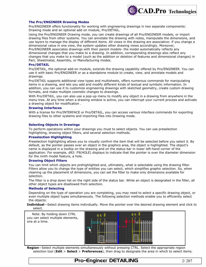
Individual—Select drawing items individually. Move the pointer over the desired drawing element and click to select.
Note: By holding down CTRL you can select multiple elements, one at a time.
Region—Select multiple elements simultaneously without pressing CTRL. Select the appropriate region
selection tool (Edit > Select > Preferences), then drag to designate the area in which to select items.
Pro-Engineer DETAILING 3/ 207
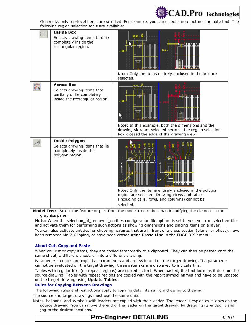
Generally, only top-level items are selected. For example, you can select a note but not the note text. The following region selection tools are available:
Inside Box Selects drawing items that lie completely inside the rectangular region.
Note: Only the items entirely enclosed in the box are selected.
Across Box Selects drawing items that partially or lie completely inside the rectangular region.
Note: In this example, both the dimensions and the drawing view are selected because the region selection box crossed the edge of the drawing view.
Inside Polygon Selects drawing items that lie completely inside the polygon region.
Note: Only the items entirely enclosed in the polygon region are selected. Drawing views and tables (including cells, rows, and columns) cannot be selected.
Model Tree—Select the feature or part from the model tree rather than identifying the element in the graphics pane.
Note: When the selection_of_removed_entities configuration file option is set to yes, you can select entities and activate them for performing such actions as showing dimensions and placing items on a layer. You can also activate entities for choosing features that are in front of a cross section (planar or offset), have been removed via Z-Clipping, or have been erased using Erase Line in the EDGE DISP menu.
About Cut, Copy and Paste When you cut or copy items, they are copied temporarily to a clipboard. They can then be pasted onto the same sheet, a different sheet, or into a different drawing. Parameters in notes are copied as parameters and are evaluated on the target drawing. If a parameter cannot be evaluated on the target drawing, three asterisks are displayed to indicate this. Tables with regular text (no repeat regions) are copied as text. When pasted, the text looks as it does on the source drawing. Tables with repeat regions are copied with the report symbol names and have to be updated on the target drawing using Update Tables. Rules for Copying Between Drawings The following rules and restrictions apply to copying detail items from drawing to drawing:
The source and target drawings must use the same units. Notes, balloons, and symbols with leaders are copied with their leader. The leader is copied as it looks on the
source drawing. You can move the end of the leader on the target drawing by dragging its endpoint and jog to the desired locations.
Pro-Engineer DETAILING 4/ 207
Notes that contain dimension parameters (that is, &d23) cannot be copied. Notes that contain other parameters can be copied.
Tables are copied as follows: Tables without repeat regions are copied as text and look the same as they do on the source drawing. Tables with repeat regions are copied with the report symbol names and have to be updated on the target
drawing using Update Tables. Undoing and Redoing Drawing Operations As you dimension and detail your drawings you can undo and redo some general operations. Such flexibility helps to ensure that the appropriate action is taken and also allows you to further explore some of the detailing capabilities. To Undo a Drawing Operation After completing the operation
Click . Press CTRL+Z. Right-click and select Undo <command name> from the shortcut menu. The <command name> indicates the
last command that supports undo/redo. Click Edit > Undo <command name>. To Restore a Drawing Operation After undoing the operation
Click . Press CTRL+Y. Right-click and select Redo <command name> from the shortcut menu. The <command name> indicates the
last command that supports undo/redo. Click Edit > Redo <command name>. You can only undo and redo some of the top level operations. For example, you can undo or redo the entire show and erase operation, but not the individual show and erase operations while the dialog is open. Note: Undo and Redo do not preserve the revision number of the object. For example, if an associative part dimension is created in the drawing, and you perform undo on dimension creation, the part and drawing are still considered modified. About View-Only Mode If you simply want to view or quickly check a drawing, you can reduce the amount of time it takes to retrieve it by opening it in View-Only mode. In View-Only mode, the system does not retrieve any of the associated model files when it opens the drawing. However, since the solid models are not in session, the system temporarily freezes the drawings, so you cannot modify them. A prerequisite to using view only mode is that the configuration option save_display is set to yes the last time the file is saved in normal mode. This lets the drawing file "remember" the 3D dimension locations and values without having to access the 3D model files. If you decide that you do need to modify a drawing in view only mode, you can use File > Retrieve Models to retrieve all of the models in mid-session. Note:
If the geometry display information of a view is missing, the system displays an empty view boundary. Since Pro/ENGINEER does not retrieve any of the associated solid models, plotting (for example, complex overlap checking) does not function the same way that it does in Drawing mode because much of the information is missing. If you store the display with snap lines in Drawing mode, the system plots them in View-Only mode.
Undoing and Redoing Drawing Operations As you dimension and detail your drawings you can undo and redo some general operations. Such flexibility helps to ensure that the appropriate action is taken and also allows you to further explore some of the detailing capabilities. To Undo a Drawing Operation After completing the operation
Click . Press CTRL+Z.
Pro-Engineer DETAILING 5/ 207
Right-click and select Undo <command name> from the shortcut menu. The <command name> indicates the last command that supports undo/redo.
Click Edit > Undo <command name>. To Restore a Drawing Operation After undoing the operation
Click . Press CTRL+Y. Right-click and select Redo <command name> from the shortcut menu. The <command name> indicates the
last command that supports undo/redo. Click Edit > Redo <command name>. You can only undo and redo some of the top level operations. For example, you can undo or redo the entire show and erase operation, but not the individual show and erase operations while the dialog is open. Note: Undo and Redo do not preserve the revision number of the object. For example, if an associative part dimension is created in the drawing, and you perform undo on dimension creation, the part and drawing are still considered modified. About View-Only Mode If you simply want to view or quickly check a drawing, you can reduce the amount of time it takes to retrieve it by opening it in View-Only mode. In View-Only mode, the system does not retrieve any of the associated model files when it opens the drawing. However, since the solid models are not in session, the system temporarily freezes the drawings, so you cannot modify them. A prerequisite to using view only mode is that the configuration option save_display is set to yes the last time the file is saved in normal mode. This lets the drawing file "remember" the 3D dimension locations and values without having to access the 3D model files. If you decide that you do need to modify a drawing in view only mode, you can use File > Retrieve Models to retrieve all of the models in mid-session. Note:
If the geometry display information of a view is missing, the system displays an empty view boundary. Since Pro/ENGINEER does not retrieve any of the associated solid models, plotting (for example, complex
overlap checking) does not function the same way that it does in Drawing mode because much of the information is missing.
If you store the display with snap lines in Drawing mode, the system plots them in View-Only mode. To Open a Drawing in View-Only Mode
Click File > Open; then click and check the Retrieve Drawing as View Only option from the list. Open the drawing. Note: Since View only mode does not access the 3D models, you must save the existing display information in normal mode by
Checking Save Display in the Tools> Environment dialog box, or, Setting the configuration file option save_display to yes. To Modify a Drawing in View-Only Mode Click File > Retrieve Models. Click Confirm in the Menu Manager. The system enters Drawing mode and retrieves all models for the
current drawing. Modify the current drawing as necessary. About Setting Up a Drawing You can customize your drawing environment and drawing behavior using a combination of:
Drawing Setup File Options Configuration Options Templates Formats For example, you may predetermine characteristics like the height of dimension and note text, text orientation, geometric tolerance standards, font properties, drafting standards, and arrow lengths. Using True Type Fonts TrueType fonts can be used with Pro/ENGINEER. Pro/ENGINEER supplies 41 TrueType fonts, and you can purchase additional TrueType fonts and place them in the Pro/ENGINEER loadpoint directory.
Pro-Engineer DETAILING 6/ 207
See the Pro/ENGINEER Installation and Administration Guide for information about where to locate the font file in the load directory area.
Note: TrueType fonts can take more time to repaint. About Drawing Setup File Options While configuration file options control the design environment for parts and assemblies, drawing setup file options add additional controls to the detailing environment. The drawing setup file options determine characteristics like the height of dimension and note text, text orientation, geometric tolerance standards, font properties, drafting standards, and arrow lengths. Default values are provided for the drawing setup file options, but you can customize and save various versions for use in other drawings. The file that you specify in the drawing_setup_file configuration option establishes the default drawing setup options for any drawing that you create during a Pro/E session. If you do not set this option, the system uses the default drawing setup file option values. You can retrieve the following sample drawing setup files from the loadpoint/text directory with the following names:
iso.dtl ISO (International Organization for Standardization) jis.dtl JIS (Japanese Institute of Standards) din.dtl DIN (Deutsches Institut für Normung / German Institute for Standardization) Pro/E saves the drawing setup file options settings with each individual drawing file. The system saves the values in a setup file named <filename>.dtl. The location of this file is determined by the pro_dtl_setup_dir configuration file option. You can specify the complete path to the directory that contains your drawing setup files. If you do not specify the pathname using this configuration file option, the system brings you into the default setup directory. Note:
If a drawing setup file option is set to default, and if a configuration file option exists with the same name the drawing setup file option refers to the configuration setting. If you set the drawing setup option to something other than default, the configuration option setting is overwritten within the drawing environment only.
The environment settings supersede configuration file settings (Tools > Environment). Therefore, if you seldom use a particular command, such as the drawing grid, you could use the configuration file option to keep it cleared and then set the environment as needed.
To Customize the Drawing Setup File Options You can customize existing drawing setup files or you can create new ones based on your detailing requirements. Click File > Properties. The File Properties menu appears on the menu manager. Click Drawing Options. The Options dialog box opens. Edit the drawing setup file options as necessary. If you are customizing an existing drawing setup file, click
and browse to the appropriate DTL file. Click Apply after making your edits. The system updates the drawing using the new setup file option values.
To save your changes, click and then type a name for the file. Note: If the newly set options do not immediately update on your drawing, do one of the following:
Click View > Repaint Click the Redraw button Click View > Update > Current Sheet or All Sheets, and then use the GET SELECT menu to select the view
you want to update. To Retrieve an Existing Drawing Setup File You can retrieve and apply an existing drawing setup file to a drawing. Several standard drawing setup files are available from the loadpoint/text directory. With the drawing file open, click File > Properties. The File Properties menu appears in the menu manager. Click Drawing Options. The Options dialog box opens.
Click and browse to the desired drawing setup file. Drawing setup file options have a DTL extension. Click Apply. The drawing setup file options are applied to the current drawing. 2d_region_columns_fit_text Determines whether each column in a two-dimensional repeat region automatically resizes to fit the longest piece of text in each column, and does not overlap adjacent columns or force large gaps in the table. Columns with no text in them use the default column width for the region (the width of the template cell). Default and Available Settings
Pro-Engineer DETAILING 7/ 207
yes—Resizes each column in 2-D repeat regions so that the longest text in the column no*—Column maintains the same size. Note: Columns of tables that contain automatically resized two-dimensional repeat regions cannot be manually resized.
allow_3D_dimensions Determines if dimensions are shown in isometric views. Default and Available Settings
no*—Dimensions are not shown in isometric views. yes—Dimensions display in isometric views.
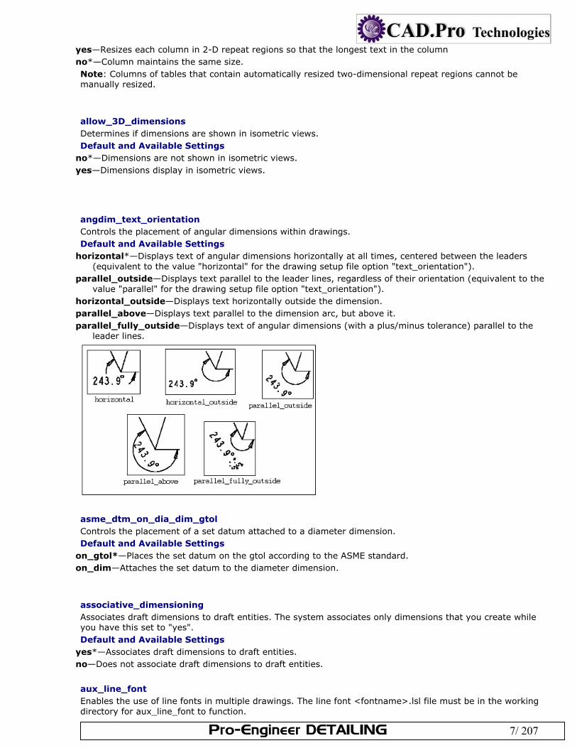
angdim_text_orientation Controls the placement of angular dimensions within drawings. Default and Available Settings
horizontal*—Displays text of angular dimensions horizontally at all times, centered between the leaders (equivalent to the value "horizontal" for the drawing setup file option "text_orientation").
parallel_outside—Displays text parallel to the leader lines, regardless of their orientation (equivalent to the value "parallel" for the drawing setup file option "text_orientation").
horizontal_outside—Displays text horizontally outside the dimension. parallel_above—Displays text parallel to the dimension arc, but above it. parallel_fully_outside—Displays text of angular dimensions (with a plus/minus tolerance) parallel to the
leader lines.
asme_dtm_on_dia_dim_gtol Controls the placement of a set datum attached to a diameter dimension. Default and Available Settings
on_gtol*—Places the set datum on the gtol according to the ASME standard. on_dim—Attaches the set datum to the diameter dimension.
associative_dimensioning Associates draft dimensions to draft entities. The system associates only dimensions that you create while you have this set to "yes". Default and Available Settings
yes*—Associates draft dimensions to draft entities. no—Does not associate draft dimensions to draft entities.
aux_line_font Enables the use of line fonts in multiple drawings. The line font <fontname>.lsl file must be in the working directory for aux_line_font to function.
Pro-Engineer DETAILING 8/ 207
This setup option is not visible in the Options dialog unless you: Create a new line font within a drawing (the option is automatically set). Manually type and set the option. Defaults and Available Settings
# font name—Where # represents a value between 1 and 10,000 and font name represents the auxiliary font you want in the drawing.
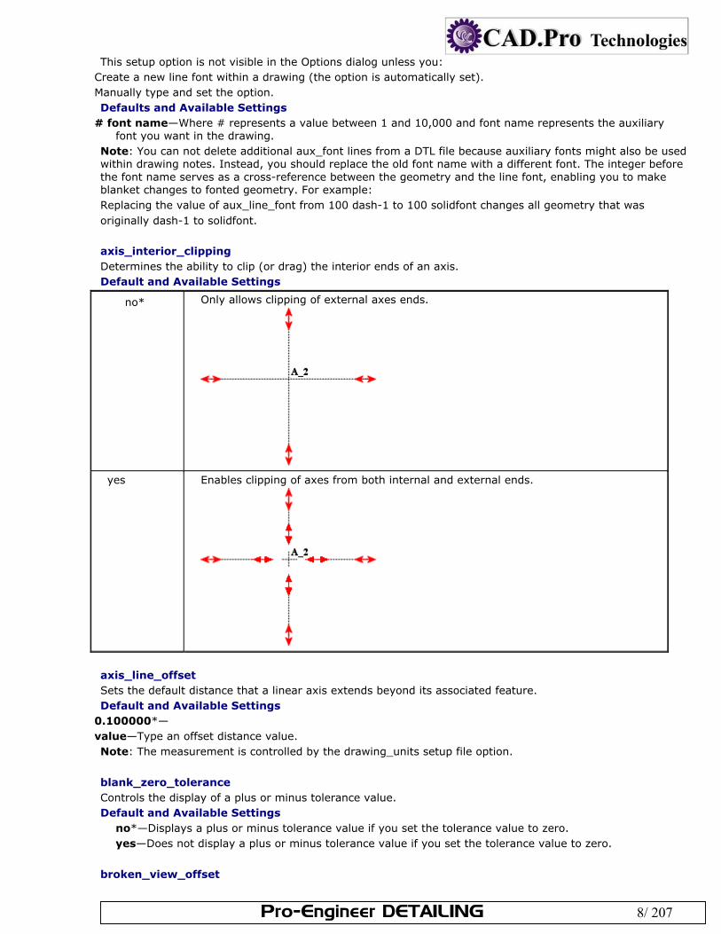
Note: You can not delete additional aux_font lines from a DTL file because auxiliary fonts might also be used within drawing notes. Instead, you should replace the old font name with a different font. The integer before the font name serves as a cross-reference between the geometry and the line font, enabling you to make blanket changes to fonted geometry. For example: Replacing the value of aux_line_font from 100 dash-1 to 100 solidfont changes all geometry that was originally dash-1 to solidfont. axis_interior_clipping Determines the ability to clip (or drag) the interior ends of an axis. Default and Available Settings
no* Only allows clipping of external axes ends.
yes Enables clipping of axes from both internal and external ends.
axis_line_offset Sets the default distance that a linear axis extends beyond its associated feature. Default and Available Settings
0.100000*— value—Type an offset distance value. Note: The measurement is controlled by the drawing_units setup file option.
blank_zero_tolerance Controls the display of a plus or minus tolerance value. Default and Available Settings
no*—Displays a plus or minus tolerance value if you set the tolerance value to zero. yes—Does not display a plus or minus tolerance value if you set the tolerance value to zero.
broken_view_offset
Pro-Engineer DETAILING 9/ 207
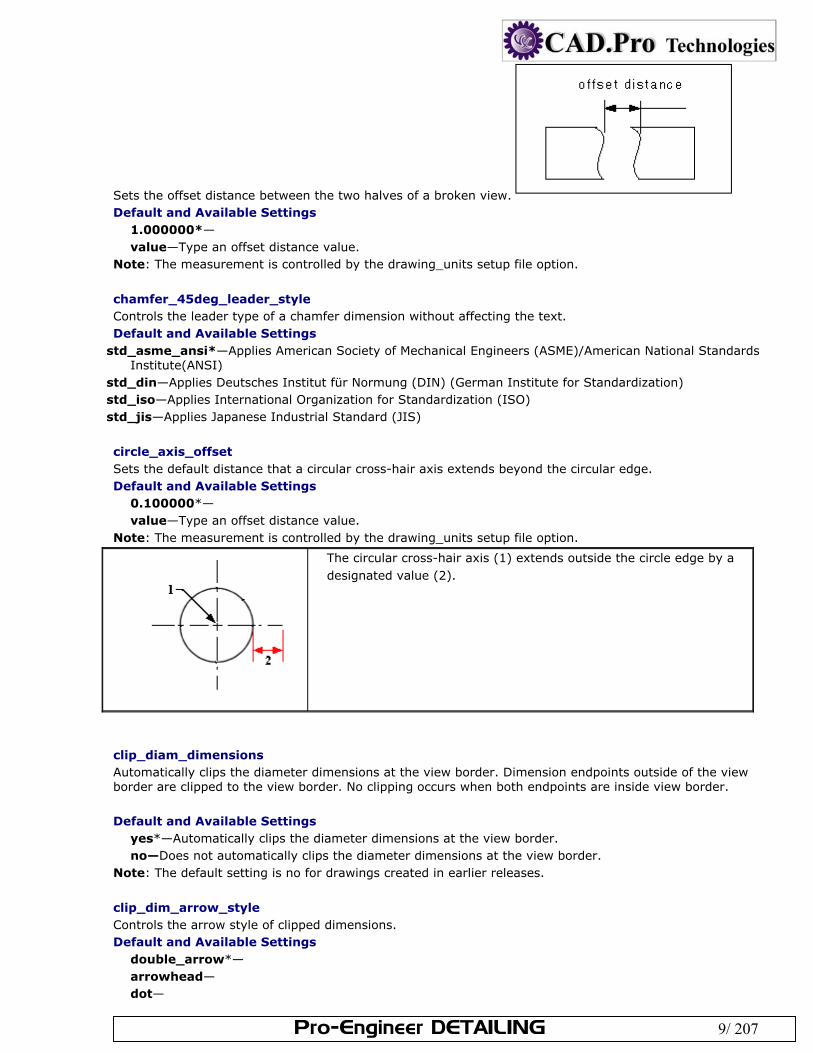
Sets the offset distance between the two halves of a broken view. Default and Available Settings
1.000000*— value—Type an offset distance value.
Note: The measurement is controlled by the drawing_units setup file option.
chamfer_45deg_leader_style Controls the leader type of a chamfer dimension without affecting the text. Default and Available Settings
std_asme_ansi*—Applies American Society of Mechanical Engineers (ASME)/American National Standards Institute(ANSI)
std_din—Applies Deutsches Institut für Normung (DIN) (German Institute for Standardization) std_iso—Applies International Organization for Standardization (ISO) std_jis—Applies Japanese Industrial Standard (JIS)
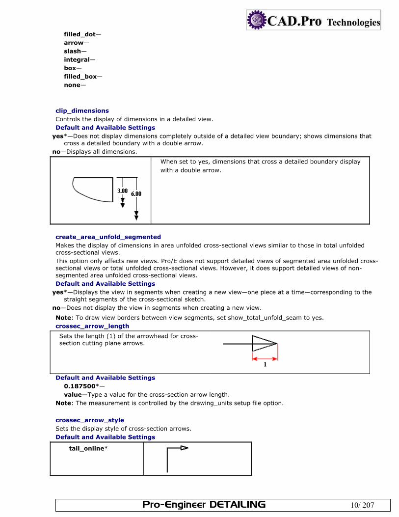
circle_axis_offset Sets the default distance that a circular cross-hair axis extends beyond the circular edge. Default and Available Settings
0.100000*— value—Type an offset distance value.
Note: The measurement is controlled by the drawing_units setup file option.
The circular cross-hair axis (1) extends outside the circle edge by a designated value (2).
clip_diam_dimensions Automatically clips the diameter dimensions at the view border. Dimension endpoints outside of the view border are clipped to the view border. No clipping occurs when both endpoints are inside view border. Default and Available Settings
yes*—Automatically clips the diameter dimensions at the view border. no—Does not automatically clips the diameter dimensions at the view border.
Note: The default setting is no for drawings created in earlier releases.
clip_dim_arrow_style Controls the arrow style of clipped dimensions. Default and Available Settings
double_arrow*— arrowhead— dot—
Pro-Engineer DETAILING 10/ 207
filled_dot— arrow— slash— integral— box— filled_box— none—
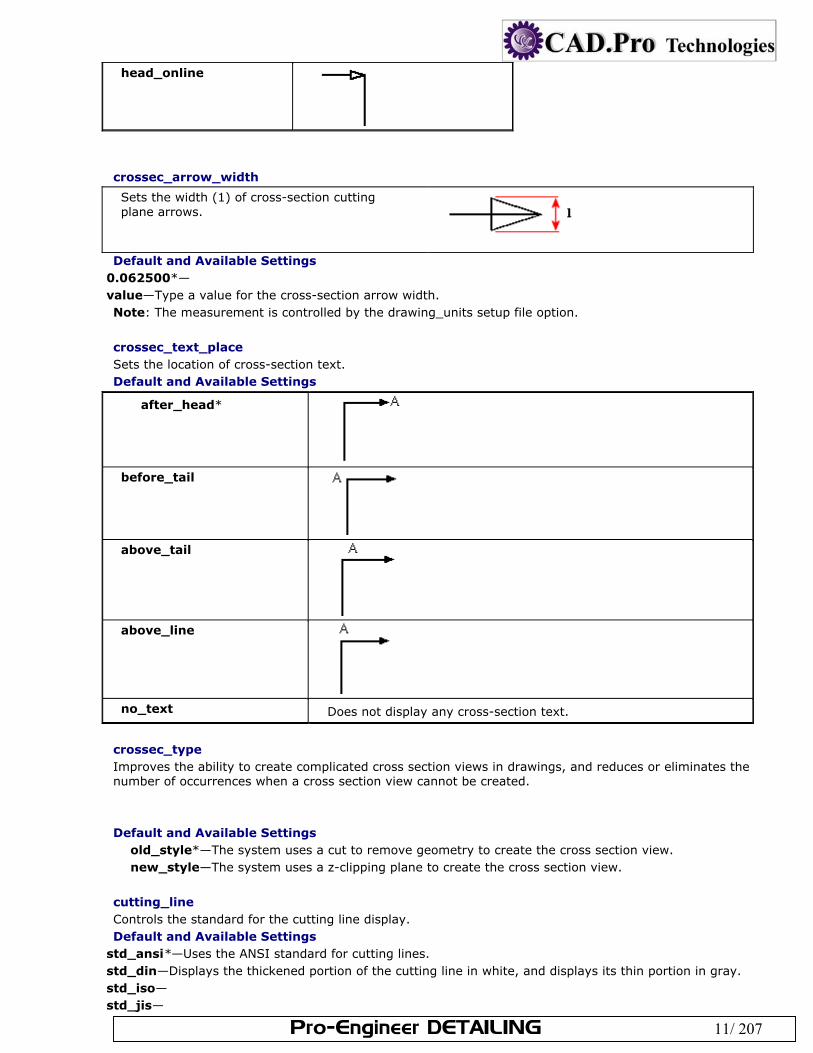
clip_dimensions Controls the display of dimensions in a detailed view. Default and Available Settings
yes*—Does not display dimensions completely outside of a detailed view boundary; shows dimensions that cross a detailed boundary with a double arrow.
no—Displays all dimensions.
When set to yes, dimensions that cross a detailed boundary display with a double arrow.
create_area_unfold_segmented Makes the display of dimensions in area unfolded cross-sectional views similar to those in total unfolded cross-sectional views. This option only affects new views. Pro/E does not support detailed views of segmented area unfolded cross-sectional views or total unfolded cross-sectional views. However, it does support detailed views of non-segmented area unfolded cross-sectional views. Default and Available Settings
yes*—Displays the view in segments when creating a new view—one piece at a time—corresponding to the straight segments of the cross-sectional sketch.
no—Does not display the view in segments when creating a new view.
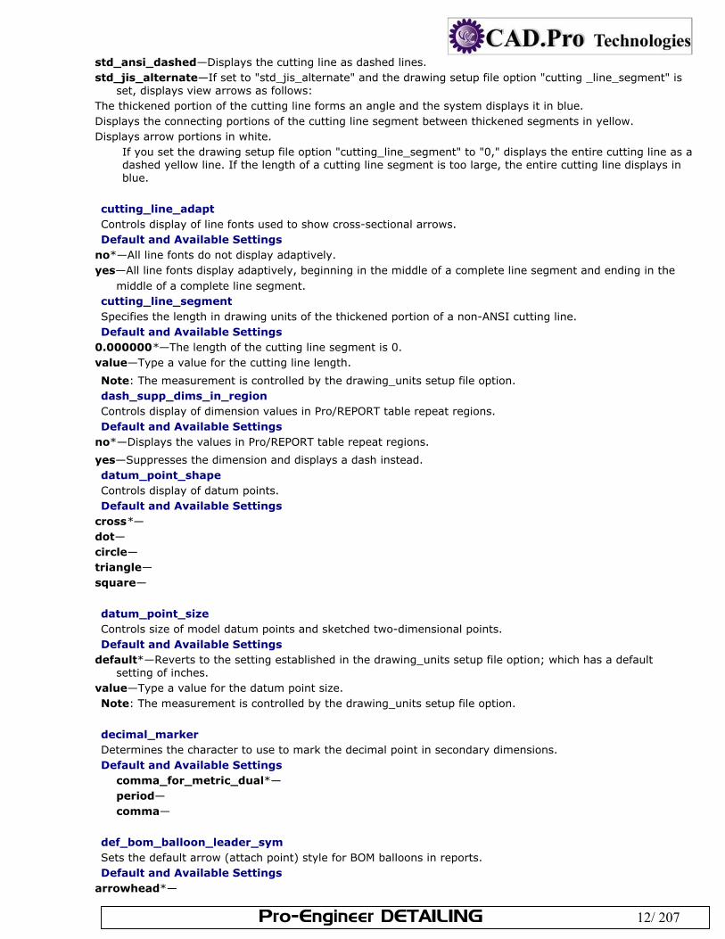
Note: To draw view borders between view segments, set show_total_unfold_seam to yes. crossec_arrow_length
Sets the length (1) of the arrowhead for cross-section cutting plane arrows.
Default and Available Settings 0.187500*— value—Type a value for the cross-section arrow length.
Note: The measurement is controlled by the drawing_units setup file option.
crossec_arrow_style Sets the display style of cross-section arrows. Default and Available Settings
tail_online*
Pro-Engineer DETAILING 11/ 207
head_online
crossec_arrow_width
Sets the width (1) of cross-section cutting plane arrows.
Default and Available Settings 0.062500*— value—Type a value for the cross-section arrow width. Note: The measurement is controlled by the drawing_units setup file option.
crossec_text_place Sets the location of cross-section text. Default and Available Settings
after_head*
before_tail
above_tail
above_line
no_text Does not display any cross-section text.
crossec_type Improves the ability to create complicated cross section views in drawings, and reduces or eliminates the number of occurrences when a cross section view cannot be created. Default and Available Settings
old_style*—The system uses a cut to remove geometry to create the cross section view. new_style—The system uses a z-clipping plane to create the cross section view.
cutting_line Controls the standard for the cutting line display. Default and Available Settings
std_ansi*—Uses the ANSI standard for cutting lines. std_din—Displays the thickened portion of the cutting line in white, and displays its thin portion in gray. std_iso— std_jis—
Pro-Engineer DETAILING 12/ 207
std_ansi_dashed—Displays the cutting line as dashed lines. std_jis_alternate—If set to "std_jis_alternate" and the drawing setup file option "cutting _line_segment" is
set, displays view arrows as follows: The thickened portion of the cutting line forms an angle and the system displays it in blue. Displays the connecting portions of the cutting line segment between thickened segments in yellow. Displays arrow portions in white.
If you set the drawing setup file option "cutting_line_segment" to "0," displays the entire cutting line as a dashed yellow line. If the length of a cutting line segment is too large, the entire cutting line displays in blue.
cutting_line_adapt Controls display of line fonts used to show cross-sectional arrows. Default and Available Settings
no*—All line fonts do not display adaptively. yes—All line fonts display adaptively, beginning in the middle of a complete line segment and ending in the
middle of a complete line segment. cutting_line_segment Specifies the length in drawing units of the thickened portion of a non-ANSI cutting line. Default and Available Settings
0.000000*—The length of the cutting line segment is 0. value—Type a value for the cutting line length.
Note: The measurement is controlled by the drawing_units setup file option. dash_supp_dims_in_region Controls display of dimension values in Pro/REPORT table repeat regions. Default and Available Settings
no*—Displays the values in Pro/REPORT table repeat regions.
yes—Suppresses the dimension and displays a dash instead. datum_point_shape Controls display of datum points. Default and Available Settings
cross*— dot— circle— triangle— square—
datum_point_size Controls size of model datum points and sketched two-dimensional points. Default and Available Settings
default*—Reverts to the setting established in the drawing_units setup file option; which has a default setting of inches.
value—Type a value for the datum point size. Note: The measurement is controlled by the drawing_units setup file option.
decimal_marker Determines the character to use to mark the decimal point in secondary dimensions. Default and Available Settings
comma_for_metric_dual*— period— comma—
def_bom_balloon_leader_sym Sets the default arrow (attach point) style for BOM balloons in reports. Default and Available Settings
arrowhead*—
Pro-Engineer DETAILING 13/ 207
dot— filled_dot— no_arrow— slash— integral— box— filled_box—
def_view_text_height Sets the height of text in view names used in view notes and in arrows in cross-sectional and projection detail views. Default and Available Settings
0.000000*— value—Type a value for the height of text in view names. Note: The measurement is controlled by the drawing_units setup file option.
def_view_text_thickness Sets default thickness for new text in view names used in view notes and in arrows in newly created cross-sectional and projection detail views. Default and Available Settings
0.000000*— value—Type a value for the thickness of text in view names. Note: The measurement is controlled by the drawing_units setup file option.
default_dim_elbows Controls display of dimension elbows. Default and Available Settings
yes*—Dimensions display with elbows. no—Dimensions do not display with elbows.
default_font Sets default text fonts as those fonts listed in the specified font index. Default and Available Settings
font*— font index name— Note: Do not include the .ndx extension. The font settings ( font and filled) are located in the setup file.
default_pipe_bend_note Controls display of pipe bend notes in drawings. If set as text within quotation marks, uses that value when creating bend notes. Text may include parameters such as "&bend_name:att_pipe_bend" and "&bend_tol: att_pipe_bend". If set as a directory path, references a previously created note saved as a file. Default and Available Settings
no*—Pipe bend notes do not display in drawings. yes—Pipe bend notes display in drawings.
detail_circle_line_style Sets line font for circles indicating a detailed view in a drawing. Default and Available Settings
Pro-Engineer DETAILING 14/ 207
You can select one of the following line styles, or you can set any available system-defined or user-defined line font.
solidfont*— dotfont— ctrlfont— phantomfont— dashfont— ctrlfont_s_l— ctrlfont_l_l— ctrlfont_s_s— dashfont_s_s— phantomfont_s_s—
detail_circle_note_text Determines the default contents of the reference note for a detailed view. For example if the value is "See View" the note text reads "See View <viewname>" Default and Available Settings
Default—
detail_view_circle Sets display of a circle drawn about the portion of a model that is detailed by a detailed view. Default and Available Settings
on*—Displays a circle about the detailed portion of a model. off—Does not display a circle about the detailed portion of a model.
dim_dot_box_style Controls the arrow style display of dots and boxes only for leaders of linear dimensions. Default and Available Settings
default*—Uses the style established in the draw_arrow_style drawing option. BOM balloon arrows are controlled by the def_bom_balloon_leader_sym drawing setup file option, which defines the default arrow (attach point) style for BOM balloons in reports.
filled—Fills dots and boxes for arrows of linear dimensions. Use "filled" to have new drawings appear with dots and boxes filled for dimension arrows.
hollow—Dots and boxes for arrows of linear dimensions are not filled.
dim_fraction_format Controls the display of fractional dimensions within drawings. This drawing setup option supersedes the configuration file option of the same name (dim_fraction_format) unless the drawing setup option is set to default. Default and Available Settings
default*—Displays fractional dimensions in drawings according to the setting of the configuration file option dim_fraction_format.
std—Displays fractional dimensions in drawings in the standard Pro/E format. aisc—Displays fractional dimensions in drawings in the AISC format. The AISC setting also displays
architectural units according to AISC format for feet-inches dimensions. Note: When you retrieve drawings created prior to Release 2000i, the dim_fraction_format and use_major_units drawing setup options combine to control the display of dimensions.
dim_leader_length
Pro-Engineer DETAILING 15/ 207
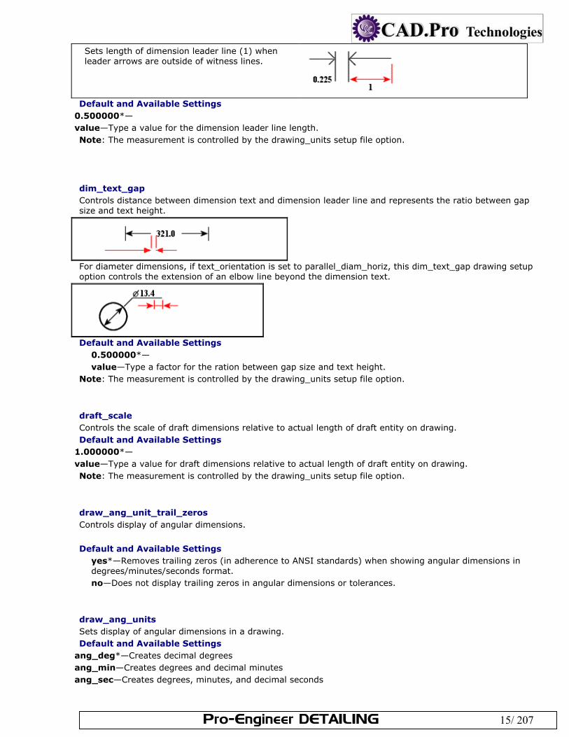
Sets length of dimension leader line (1) when leader arrows are outside of witness lines.
Default and Available Settings
0.500000*— value—Type a value for the dimension leader line length. Note: The measurement is controlled by the drawing_units setup file option.
dim_text_gap Controls distance between dimension text and dimension leader line and represents the ratio between gap size and text height.
For diameter dimensions, if text_orientation is set to parallel_diam_horiz, this dim_text_gap drawing setup option controls the extension of an elbow line beyond the dimension text.
Default and Available Settings
0.500000*— value—Type a factor for the ration between gap size and text height.
Note: The measurement is controlled by the drawing_units setup file option.
draft_scale Controls the scale of draft dimensions relative to actual length of draft entity on drawing. Default and Available Settings
1.000000*— value—Type a value for draft dimensions relative to actual length of draft entity on drawing. Note: The measurement is controlled by the drawing_units setup file option.
draw_ang_unit_trail_zeros Controls display of angular dimensions. Default and Available Settings
yes*—Removes trailing zeros (in adherence to ANSI standards) when showing angular dimensions in degrees/minutes/seconds format. no—Does not display trailing zeros in angular dimensions or tolerances.
draw_ang_units Sets display of angular dimensions in a drawing. Default and Available Settings
ang_deg*—Creates decimal degrees ang_min—Creates degrees and decimal minutes ang_sec—Creates degrees, minutes, and decimal seconds
Pro-Engineer DETAILING 16/ 207
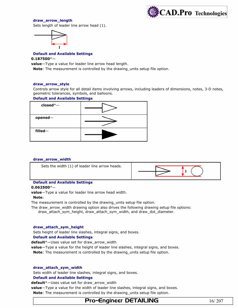
draw_arrow_length Sets length of leader line arrow head (1).
Default and Available Settings
0.187500*— value—Type a value for leader line arrow head length. Note: The measurement is controlled by the drawing_units setup file option.
draw_arrow_style Controls arrow style for all detail items involving arrows, including leaders of dimensions, notes, 3-D notes, geometric tolerances, symbols, and balloons. Default and Available Settings
closed*—
opened—
filled—
draw_arrow_width
Sets the width (1) of leader line arrow heads.
Default and Available Settings
0.062500*— value—Type a value for leader line arrow head width. Note:
The measurement is controlled by the drawing_units setup file option. The draw_arrow_width drawing option also drives the following drawing setup file options:
draw_attach_sym_height, draw_attach_sym_width, and draw_dot_diameter.
draw_attach_sym_height Sets height of leader line slashes, integral signs, and boxes. Default and Available Settings
default*—Uses value set for draw_arrow_width value—Type a value for the height of leader line slashes, integral signs, and boxes. Note: The measurement is controlled by the drawing_units setup file option.
draw_attach_sym_width Sets width of leader line slashes, integral signs, and boxes. Default and Available Settings
default*—Uses value set for draw_arrow_width value—Type a value for the width of leader line slashes, integral signs, and boxes. Note: The measurement is controlled by the drawing_units setup file option.
Pro-Engineer DETAILING 17/ 207
draw_cosms_in_area_xsec Controls display of cosmetic sketches and datum curve features that lie in the cutting plane in planar area cross-sectional views. Default and Available Settings
no*—Does not show all cosmetic sketches and datum curve features that lie in the cutting plane. yes—Shows all cosmetic sketches and datum curve features that lie in the cutting plane.
draw_dot_diameter Sets diameter of leader line dots. Default and Available Settings
default*—Uses the value set in the draw_arrow_width drawing setup file option. value—Type a value for the diameter of leader line dots. Note: The measurement is controlled by the drawing_units setup file option.
draw_layer_overrides_model Directs drawing layer display setting to determine the setting of drawing model layers with the same name. Default and Available Settings
no*—Ignores nondrawing layers when the display status of layers is set in the drawing model. yes—Implicitly includes drawing model layers in drawing layers with the same name for purposes of setting
the display.
drawing_text_height Sets default text height for all text within the drawing. Default and Available Settings
0.156250*—Uses the value set in the draw_arrow_width drawing setup file option. value—Type a value for the height of all text within drawings. Note: The measurement is controlled by the drawing_units setup file option.
drawing_units Sets unit formatting for all drawing setup file options and parameters. Default and Available Settings
inch*— foot— mm— cm— m—
dual_digits_diff Controls number of digits to the right of the decimal that the secondary dimension differs from primary dimension. For example, using the default value -1 results in the following when primary units are inches and secondary units are millimeters: 10.235 [259.96]. Default and Available Settings
-1*— value—Type a value for the number of digits to the right of the decimal that the secondary dimension differs
from primary dimension.
dual_dimension_brackets Controls display of brackets with dimension units. Default and Available Settings
yes*—Displays dimension units that occur second in brackets;
Pro-Engineer DETAILING 18/ 207
no—Does not display brackets. Note: This drawing setup file option only works when you also set the dual_dimensioning drawing setup option.
dual_dimensioning Controls the formatting of dimension display; whether or not dual dimensions are used and also how they display. Default and Available Settings
no*—Displays a single value for dimensions. primary [secondary]—Displays dimensions with primary units (established by the model) and secondary
units. secondary—Only displays the secondary dimensions of the drawing, as if they were primary. Note: The following drawing setup file options can be used in conjunction with this option to modify the display of dual dimensions:
dual_secondary_units specifies the secondary set of units used by the drawing. dual_digits_diff specifies the number of decimal places that secondary units contain compared with the
primary units used. decimal_marker specifies the character to use to mark the decimal point in secondary dimensions. dual_dimension_brackets specifies whether one of the units of dimensions appears within brackets.
dual_metric_dim_show_fractions Determines whether the metric portion of dual dimension will display fractions when the primary/model units are fractions. Defaults and Available Settings
no*—Dual dimensions do not display as fractions when the primary/model units are fractions.. yes—Dual dimensions display as fractions when the primary/model units are fractions.
dual_secondary_units Sets the unit formatting for the secondary dimensions in dual dimension schemes. Default and Available Settings
mm*— inch— foot— cm— m—
gtol_datum_placement_default Determines whether the set datum is attached above or below the geometric tolerance control frame. Defaults and Available Settings
on_bottom*—Places set datum on the bottom of the control frame.
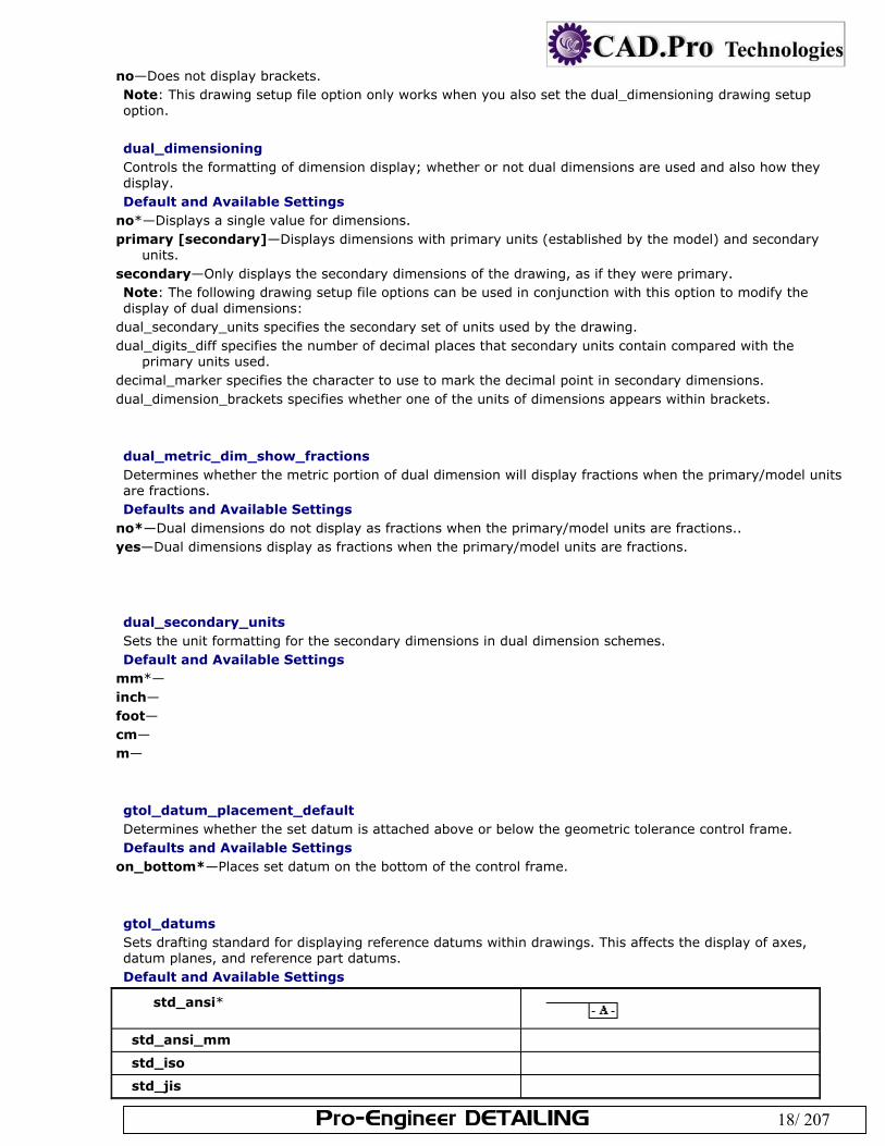
gtol_datums Sets drafting standard for displaying reference datums within drawings. This affects the display of axes, datum planes, and reference part datums. Default and Available Settings
std_ansi*
std_ansi_mm
std_iso
std_jis
Pro-Engineer DETAILING 19/ 207
std_din
std_iso_jis
std_ansi_dashed
std_asme
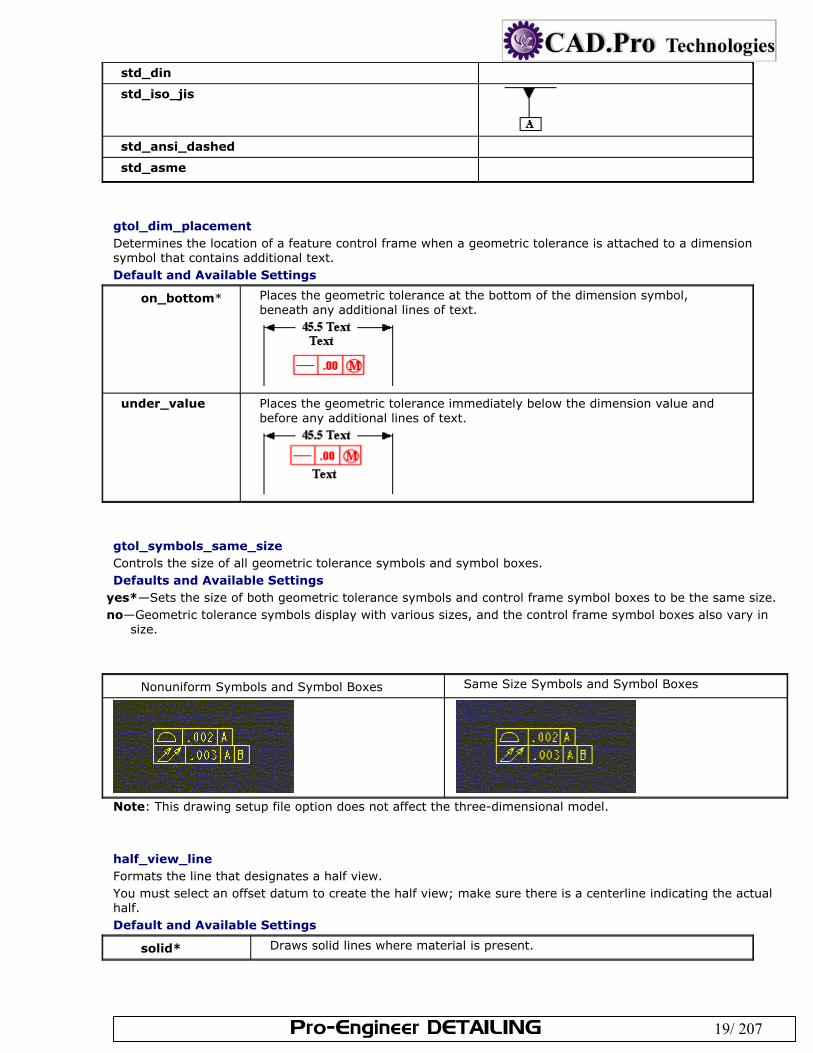
gtol_dim_placement Determines the location of a feature control frame when a geometric tolerance is attached to a dimension symbol that contains additional text. Default and Available Settings
on_bottom* Places the geometric tolerance at the bottom of the dimension symbol, beneath any additional lines of text.
under_value Places the geometric tolerance immediately below the dimension value and before any additional lines of text.
gtol_symbols_same_size Controls the size of all geometric tolerance symbols and symbol boxes. Defaults and Available Settings
yes*—Sets the size of both geometric tolerance symbols and control frame symbol boxes to be the same size. no—Geometric tolerance symbols display with various sizes, and the control frame symbol boxes also vary in
size.
Nonuniform Symbols and Symbol Boxes Same Size Symbols and Symbol Boxes
Note: This drawing setup file option does not affect the three-dimensional model.
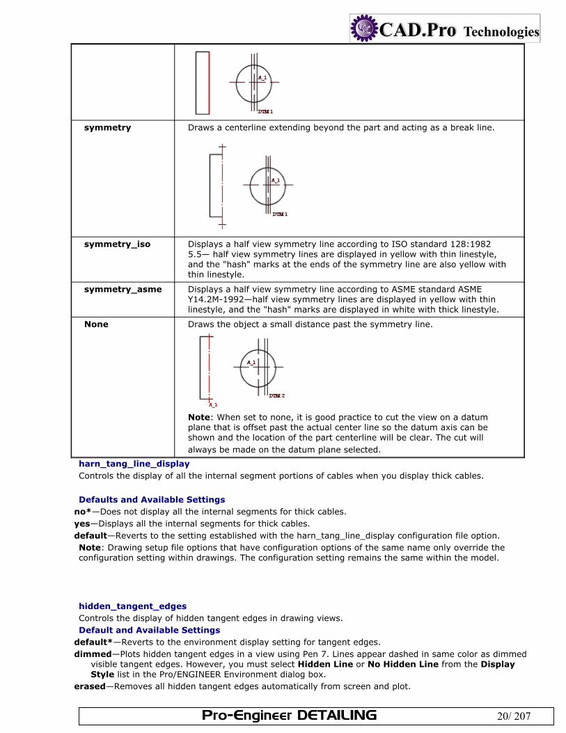
half_view_line Formats the line that designates a half view. You must select an offset datum to create the half view; make sure there is a centerline indicating the actual half. Default and Available Settings
solid* Draws solid lines where material is present.
Pro-Engineer DETAILING 20/ 207
symmetry Draws a centerline extending beyond the part and acting as a break line.
symmetry_iso Displays a half view symmetry line according to ISO standard 128:1982 5.5— half view symmetry lines are displayed in yellow with thin linestyle, and the "hash" marks at the ends of the symmetry line are also yellow with thin linestyle.
symmetry_asme Displays a half view symmetry line according to ASME standard ASME Y14.2M-1992—half view symmetry lines are displayed in yellow with thin linestyle, and the "hash" marks are displayed in white with thick linestyle.
None Draws the object a small distance past the symmetry line.
Note: When set to none, it is good practice to cut the view on a datum plane that is offset past the actual center line so the datum axis can be shown and the location of the part centerline will be clear. The cut will always be made on the datum plane selected.
harn_tang_line_display Controls the display of all the internal segment portions of cables when you display thick cables. Defaults and Available Settings
no*—Does not display all the internal segments for thick cables. yes—Displays all the internal segments for thick cables. default—Reverts to the setting established with the harn_tang_line_display configuration file option. Note: Drawing setup file options that have configuration options of the same name only override the configuration setting within drawings. The configuration setting remains the same within the model.
hidden_tangent_edges Controls the display of hidden tangent edges in drawing views. Default and Available Settings
default*—Reverts to the environment display setting for tangent edges. dimmed—Plots hidden tangent edges in a view using Pen 7. Lines appear dashed in same color as dimmed
visible tangent edges. However, you must select Hidden Line or No Hidden Line from the Display Style list in the Pro/ENGINEER Environment dialog box.
erased—Removes all hidden tangent edges automatically from screen and plot.
Pro-Engineer DETAILING 21/ 207
hlr_for_pipe_solid_cl Controls the display of pipe centerlines. This drawing setup option only operates on pipes created in Pro/PIPING, not on pipe features in a part. Default and Available Settings
no*—Hidden line removal does not affect pipe centerlines. yes—Hidden line removal affects pipe centerlines.
hlr_for_threads Controls display of threads in a drawing depending on whether it complies with the ISO or ANSI standard (set by the thread_standard drawing setup option). Default and Available Settings
no*—Displays thread edges as surfaces as they would be in Part mode. yes—Thread edges meet ANSI or ISO standard for Hidden Line display.
ignore_model_layer_status Controls whether tmodel layer status is considered in drawings . Default and Available Settings
yes*—Ignores changes to all layer status in the models of the drawing made in another mode. no—Considers model layer status within drawings.
iso_ordinate_delta Improves display of offset between an ISO-ordinate dimension line and witness line, referred to as the witness line delta. Default and Available Settings
no*—Does not display offset exactly in accordance with the specified value (it is "off" by about 2 millimeters). yes—Displays offset correctly, according to value specified for the drawing setup file option
witness_line_delta.
lead_trail_zeros Controls display of leading and trail zeros in dimensions. Default and Available Settings
std_default*—Displays the dimension or parameter according to its units. std_metric— std_english— both—Displays both leading and trailing zeros in dimensions or parameters, regardless of whether metric or
English units are used. Note:
If the lead_trail_zeros_scope drawing setup option is set to all, lead_trail_zeros also controls the display of leading and trail zeros for dimensions and all floating point parameters on a drawing, including parametric notes, view scale notes, tables, symbols, and cosmetic thread notes. When dual dimensioning is used, controls the use of leading and trailing zeros in both standards independently. If the units in the "dual_dimensioning" drawing setup file option are "primary[secondary],"
"std_english[std_metric]" shows the primary units values with trailing zeros, while the secondary units show values with leading zeros.
If the units in the "dual_dimensioning" drawing setup file option are "secondary[primary]," "std_english [std_metric]" secondary units show values with trailing zeros, while the primary units show values with leading zeros.
lead_trail_zeros_scope Controls whether only dimensions are affected by the setting of the drawing setup option lead_trail_zeros.
Pro-Engineer DETAILING 22/ 207
Default and Available Settings dims*—The drawing setup option lead_trail_zeros controls only dimensions. all—The drawing setup option lead_trail_zeros controls dimensions and also all parameters, including parametric notes, view scale notes, tables, symbols, and cosmetic thread notes.
leader_elbow_length Determines length of leader elbow (the horizontal leg attached to text). Default and Available Settings
0.250000*— value—Type a value for the length of leader elbow. Note: The measurement is controlled by the drawing_units setup file option.
line_style_length Sets the font length for two-dimension sketched entities You must add this option to the drawing setup file whenever you want to modify the length. You must also set the drawing setup file option axis_interior_clipping to no. The length measurement is controlled by the drawing_units setup file option. Default and Available Settings
font_name default*—Type the font name and then a desired value for the font length in system units. The "default" setting indicates default length values.
font_name value—Type the font name and then a desired value for the font length in system units. Note: After you add line_style_length to the drawing setup file, you cannot delete it by deleting the row from the file or by retrieving a different DTL file into the drawing. You must change the value of this option to default to eliminate the option from the drawing setup file. Use the following format:
line_style_length font_name value/default where font_name is the name of the font that you want to modify, value is the desired value for the font length in system units, and default tells the system to use the default length value.
line_style_standard Controls text color in drawings. Unless you set this option to std_ansi, all drawing text displays in blue, and the boundaries of detailed views display in yellow. Default and Available Settings
std_ansi*—Applies American National Standards Institute (ANSI) std_iso—Applies International Organization for Standardization (ISO) std_jis—Applies Japanese Industrial Standard (JIS) std_din—Applies Deutsches Institut für Normung (DIN) (German Institute for Standardization)
location_radius Modifies radius of nodes indicating location, improving their visibility, particularly when printing drawings. Default and Available Settings
default (2.)*—Sets radius as 2 drawing units. 0.0—Displays location nodes, but does not print them. There is no maximum value for this setting. value—Type a value for the radius of nodes indicating location. Note: The measurement is controlled by the drawing_units setup file option.
max_balloon_radius Sets the maximum allowable balloon radius. Default and Available Settings
0.000000*—Balloon radius depends only on text size.
Pro-Engineer DETAILING 23/ 207
value—Type a value for the maximum allowable balloon radius. Note: The measurement is controlled by the drawing_units setup file option.
mesh_surface_lines Controls display of blue surface mesh lines. Default and Available Settings
on*—Blue surface mesh lines display. off—Blue surface mesh lines do not display.
min_balloon_radius Sets minimum allowable balloon radius. Default and Available Settings
0.000000*—Balloon radius depends only on text size. value—Type a value for the minimum allowable balloon radius.
Note: The measurement is controlled by the drawing_units setup file option.
model_digits_in_region Controls display of number of digits in two-dimensional repeat regions. Default and Available Settings
yes*—Two-dimensional repeat regions reflect the number of digits of part and assembly model dimensions. no—Two-dimensional repeat region digits are independent of the part and assembly model dimension settings.
model_display_for_new_views Specifies the view display for hidden lines. Default and Available Settings
default*—Reverts to the environment setting. wireframe—Displays the view in wireframe. hidden_line—Displays the view with hidden lines. no_hidden—Displays the view without showing hidden lines. save_environment—Saves and uses the environment setting for newly created views within the drawing.
model_grid_balloon_display Determines whether a circle will be drawn around the model grid text. Defaults and Available Settings
yes*—Draws a circle around the model grid text. no—Does not draw a circle around the model grid text.
model_grid_balloon_size Specifies default radius of balloons shown with the model grid in a drawing. Default and Available Settings
0.200000*— value—Type a value for the default model grid balloon radius. Note: The measurement is controlled by the drawing_units setup file option.
Pro-Engineer DETAILING 24/ 207
model_grid_neg_prefix Controls prefix of negative values shown in model grid balloons. Default and Available Settings
- *— any string—
model_grid_num_dig_display Controls number of digits displayed in grid coordinates that appear in grid balloons. Default and Available Settings
0*—The system default (0) to display coordinates as integers. value—Type a value for the number of digits displayed in grid coordinates.
Note: The measurement is controlled by the drawing_units setup file option.
model_grid_offset Controls offset of new model grid balloons from the drawing view. Default and Available Settings
default*—Offsets new model grid balloons from the drawing view by twice the current model grid spacing. value—Type a value for the offset of model grid balloons from the drawing. Note: The measurement is controlled by the drawing_units setup file option.
model_grid_text_orientation Determines whether the model grid text orientation will be parallel to the grid lines or always horizontal. Defaults and Available Settings
horizontal*—Always displays the model grid text horizontal to the grid lines. parallel—Displays the model grid text parallel to the grid lines.
model_grid_text_position Determines whether the model grid text will appear above, below, or centered about the grid line. Defaults and Available Settings
centered*—Centers the model grid text about the grid line. above—Places the model grid text above the grid line. below—Places the model grid text below the grid line. Note: If you set the model_grid_text_orientation drawing setup file option to horizontal, model_grid_text_position is ignored.
new_iso_set_datums Controls display of set datums according to ISO standards. Default and Available Settings
yes*—Displays set draft datums according to ISO standards. no—Does not display set draft datums according to ISO standards.
node_radius Controls display of nodes in symbols. Default and Available Settings
default*—The system specifies radius of nodes. value—Type a value for the radius of nodes within symbols. If the setting is so small that the nodes do not
appear, the system uses the default setting. There is no maximum value for this setting. Note: The measurement is controlled by the drawing_units setup file option.
Pro-Engineer DETAILING 25/ 207
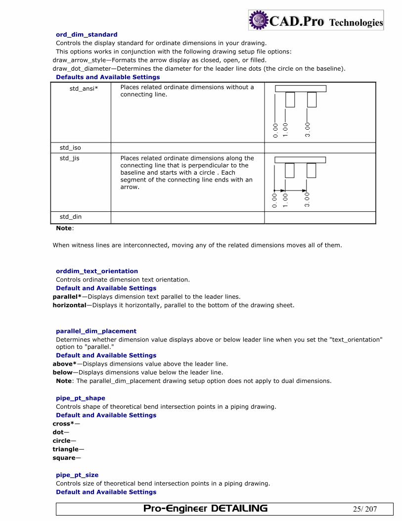
ord_dim_standard Controls the display standard for ordinate dimensions in your drawing. This options works in conjunction with the following drawing setup file options:
draw_arrow_style—Formats the arrow display as closed, open, or filled. draw_dot_diameter—Determines the diameter for the leader line dots (the circle on the baseline). Defaults and Available Settings
std_ansi* Places related ordinate dimensions without a connecting line.
std_iso
std_jis Places related ordinate dimensions along the connecting line that is perpendicular to the baseline and starts with a circle . Each segment of the connecting line ends with an arrow.
std_din
Note:
When witness lines are interconnected, moving any of the related dimensions moves all of them.
orddim_text_orientation Controls ordinate dimension text orientation. Default and Available Settings
parallel*—Displays dimension text parallel to the leader lines. horizontal—Displays it horizontally, parallel to the bottom of the drawing sheet.
parallel_dim_placement Determines whether dimension value displays above or below leader line when you set the "text_orientation" option to "parallel." Default and Available Settings
above*—Displays dimensions value above the leader line. below—Displays dimensions value below the leader line. Note: The parallel_dim_placement drawing setup option does not apply to dual dimensions.
pipe_pt_shape Controls shape of theoretical bend intersection points in a piping drawing. Default and Available Settings
cross*— dot— circle— triangle— square—
pipe_pt_size Controls size of theoretical bend intersection points in a piping drawing. Default and Available Settings
Pro-Engineer DETAILING 26/ 207
default*— value—Type a value for the size of theoretical bend interection points in piping drawings. Note: The measurement is controlled by the drawing_units setup file option.
pos_loc_format Controls the appearance of &pos_loc text both in notes and report tables. The character pairs %% are used in the following ways:
%s indicates single sheet %x and %y indicate the horizontal and vertical positions %r indicates the end of a repeatable substring Defaults and Available settings Type the desired character pairs to determine the appearance of &pos_loc text, such as %s%x%y, %r
projection_type Determines method for creating projection views. Default and Available Settings
third_angle*— first_angle—
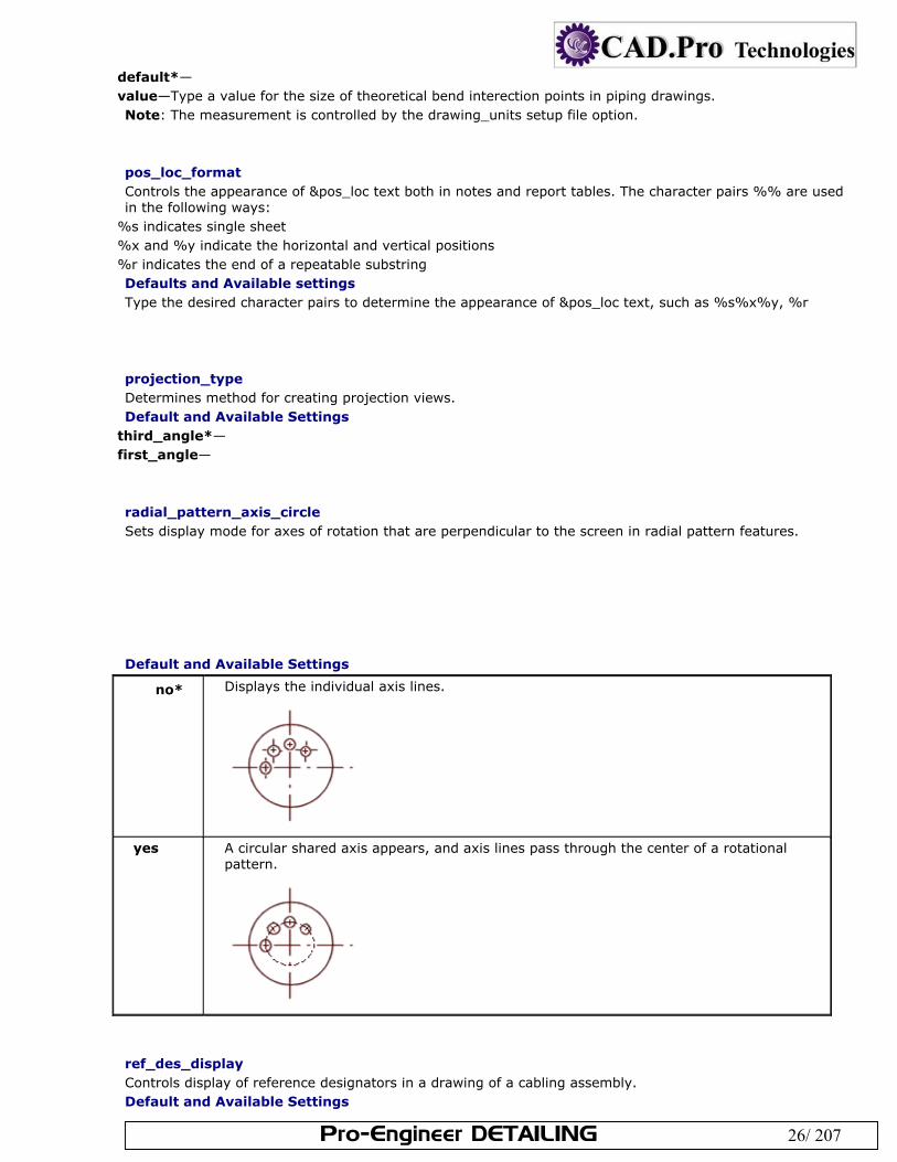
radial_pattern_axis_circle Sets display mode for axes of rotation that are perpendicular to the screen in radial pattern features. Default and Available Settings
no* Displays the individual axis lines.
yes A circular shared axis appears, and axis lines pass through the center of a rotational pattern.
ref_des_display Controls display of reference designators in a drawing of a cabling assembly. Default and Available Settings
Pro-Engineer DETAILING 27/ 207
no*—Does not display reference designators in drawings. yes—Displays reference designators in drawings. default—Automatically selects the Reference Designators environment setting.
remove_cosms_from_xsecs Controls display of datum curves, threads, cosmetic feature entities, and cosmetic cross-hatching in a full cross-sectional view. Default and Available Settings
total*—Removes features located entirely in front of the cutting plane from the cross-sectional view. Displays these features in full only if they intersect the cutting plane.
all—Removes datums and cosmetics from all types of cross-sectional views. none—Displays all datum quilts and cosmetic features.
select_hidden_edges_in_dwg Controls the selection of hidden edges in drawings. Default and Available Settings
yes*—Allows you to select hidden edges within drawings. no— Disallows selecting hidden edges by rejecting edges behind the first surface at the selection point.
restricted_gtol_dialog Controls the restrictions in the Geometric Tolerance Dialog. Default and Available Settings
yes*—The dialog will adhere to standards when picking certain GTOL types. no—The dialog drops all restrictions.
show_cbl_term_in_region Allows use of the report symbols &asm.mbr.name and &asm.mbr.type to show terminators in Pro/REPORT tables for cable assemblies having connectors with terminator parameters. Default and Available Settings
no*—For existing drawings, the default value is no. yes—Shows terminators. You must set the attribute Cable Info for the repeat region. When creating new drawings, the default value is yes.
show_pipe_theor_cl_pts Controls display of centerlines and theoretical intersection points in piping drawings. Default and Available Settings
bend_cl*—Shows centerlines with bends only. theor_cl—Shows only centerlines with theoretical bend intersection points. both—Shows both bends and theoretical intersection points.
show_preview_default Determines the default behavior for preview in the Show/Erase dialog. Default and Available Settings
remove*—Sets the default to be Sel to Remove. keep—Sets the default to be Sel to Keep.
show_quilts_in_total_xsecs
Pro-Engineer DETAILING 28/ 207
Determines if surface geometry is included in a drawing cross section and whether the surface will be cut by the cross section cutting plane. Surface geometry (surfaces and surface quilts) will only be cut by the cross-section cutting plane in a drawing view when the cross-section is created in part or assembly mode. If the cross-section is created as a Model (default), the surface geometry will not be cut by the cutting plane. Default and Available Settings
no*—Exclude surface geometry. yes—Include surface geometry.
show_total_unfold_seam Controls display of seams (the edges of the cutting plane) in total unfolded cross-sectional views. Default and Available Settings
yes* Displays the seams (the edges of the cutting plane).
no Blanks the seams (the edges of the cutting plane).
shrinkage_value_display Displays dimension shrinkage in percentages or as final values. Default and Available Settings
percent_shrink*— final_value—
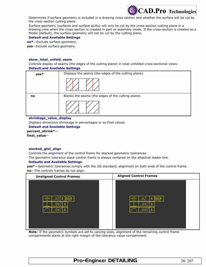
stacked_gtol_align Controls the alignment of the control frame for stacked geometric tolerances. The geometric tolerance stack control frame is always centered on the attached leader line. Defaults and Available Settings
yes*—Geometric tolerances comply with the JIS standard; alignment on both ends of the control frame. no—The controls frames do not align.
Unaligned Control Frames Aligned Control Frames
Note: If the geometric symbols are set to varying sizes, alignment of the remaining control frame compartments starts at the right margin of the tolerance value compartment.
Pro-Engineer DETAILING 29/ 207
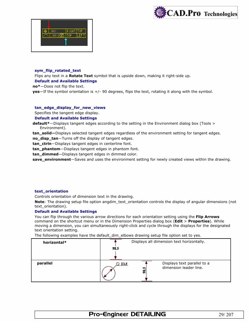
sym_flip_rotated_text Flips any text in a Rotate Text symbol that is upside down, making it right-side up. Default and Available Settings
no*—Does not flip the text. yes—If the symbol orientation is +/- 90 degrees, flips the text, rotating it along with the symbol.
tan_edge_display_for_new_views Specifies the tangent edge display. Default and Available Settings
default*—Displays tangent edges according to the setting in the Environment dialog box (Tools > Environment).
tan_solid—Displays selected tangent edges regardless of the environment setting for tangent edges. no_disp_tan—Turns off the display of tangent edges. tan_ctrln—Displays tangent edges in centerline font. tan_phantom—Displays tangent edges in phantom font. tan_dimmed—Displays tangent edges in dimmed color. save_environment—Saves and uses the environment setting for newly created views within the drawing.
text_orientation Controls orientation of dimension text in the drawing. Note: The drawing setup file option angdim_text_orientation controls the display of angular dimensions (not text_orientation). Default and Available Settings You can flip through the various arrow directions for each orientation setting using the Flip Arrows command on the shortcut menu or in the Dimension Properties dialog box (Edit > Properties). While moving a dimension, you can simultaneously right-click and cycle through the displays for the designated text orientation setting. The following examples have the default_dim_elbows drawing setup file option set to yes.
horizontal* Displays all dimension text horizontally.
parallel Displays text parallel to a dimension leader line.
Pro-Engineer DETAILING 30/ 207
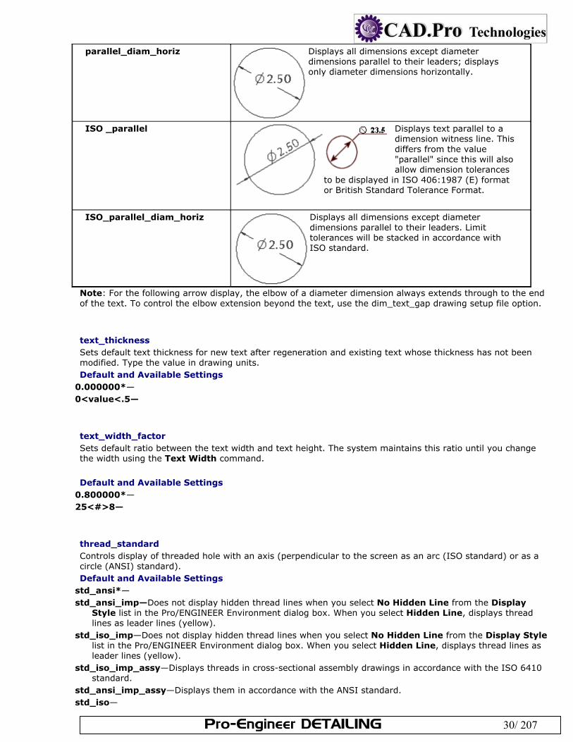
parallel_diam_horiz Displays all dimensions except diameter dimensions parallel to their leaders; displays only diameter dimensions horizontally.
ISO _parallel Displays text parallel to a dimension witness line. This differs from the value "parallel" since this will also allow dimension tolerances
to be displayed in ISO 406:1987 (E) format or British Standard Tolerance Format.
ISO_parallel_diam_horiz Displays all dimensions except diameter dimensions parallel to their leaders. Limit tolerances will be stacked in accordance with ISO standard.
Note: For the following arrow display, the elbow of a diameter dimension always extends through to the end of the text. To control the elbow extension beyond the text, use the dim_text_gap drawing setup file option.
text_thickness Sets default text thickness for new text after regeneration and existing text whose thickness has not been modified. Type the value in drawing units. Default and Available Settings
0.000000*— 0<value<.5—
text_width_factor Sets default ratio between the text width and text height. The system maintains this ratio until you change the width using the Text Width command. Default and Available Settings
0.800000*— 25<#>8—
thread_standard Controls display of threaded hole with an axis (perpendicular to the screen as an arc (ISO standard) or as a circle (ANSI) standard). Default and Available Settings
std_ansi*— std_ansi_imp—Does not display hidden thread lines when you select No Hidden Line from the Display
Style list in the Pro/ENGINEER Environment dialog box. When you select Hidden Line, displays thread lines as leader lines (yellow).
std_iso_imp—Does not display hidden thread lines when you select No Hidden Line from the Display Style list in the Pro/ENGINEER Environment dialog box. When you select Hidden Line, displays thread lines as leader lines (yellow).
std_iso_imp_assy—Displays threads in cross-sectional assembly drawings in accordance with the ISO 6410 standard.
std_ansi_imp_assy—Displays them in accordance with the ANSI standard. std_iso—
Pro-Engineer DETAILING 31/ 207
Note: The std_iso and std_ansi values are valid for drawings created before Release 15.0.
tol_display Controls display of dimension tolerances. Default and Available Settings
no*—Does not display dimension tolerances. yes—Displays dimension tolerances. Note: Drawing setup file options that have configuration options of the same name only override the configuration setting within drawings. The configuration setting remains the same within the model.
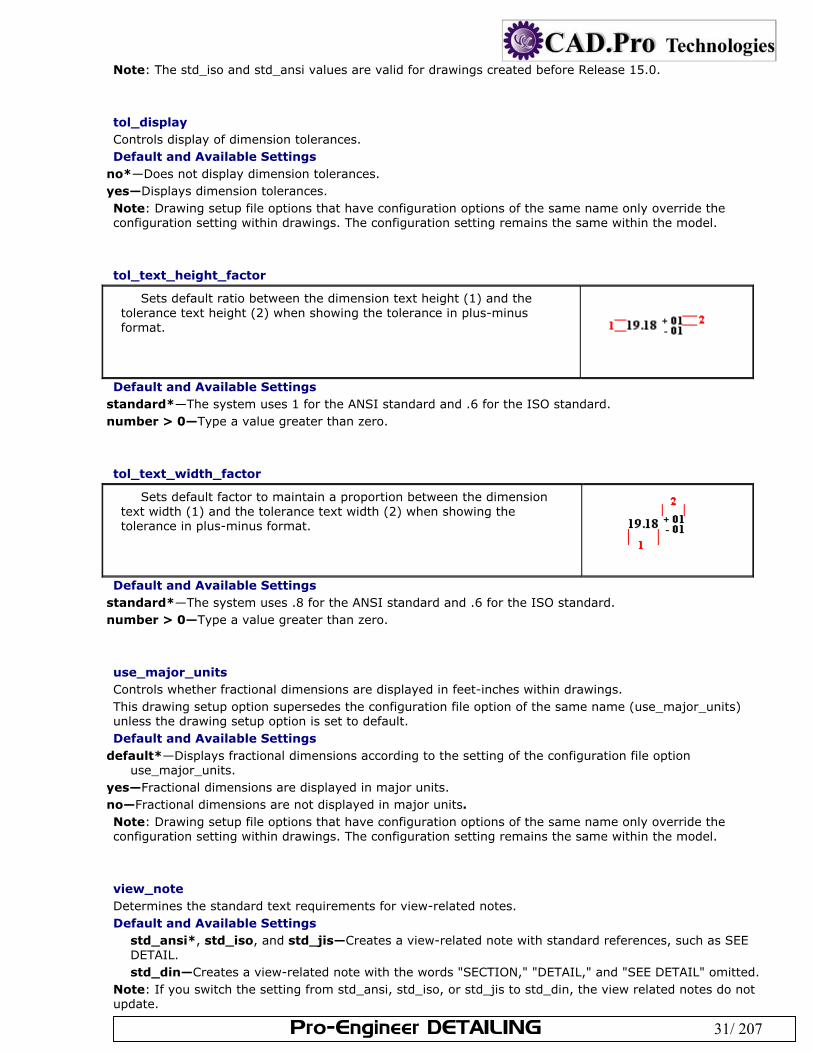
tol_text_height_factor
Sets default ratio between the dimension text height (1) and the tolerance text height (2) when showing the tolerance in plus-minus format.
Default and Available Settings
standard*—The system uses 1 for the ANSI standard and .6 for the ISO standard. number > 0—Type a value greater than zero.
tol_text_width_factor
Sets default factor to maintain a proportion between the dimension text width (1) and the tolerance text width (2) when showing the tolerance in plus-minus format.
Default and Available Settings
standard*—The system uses .8 for the ANSI standard and .6 for the ISO standard. number > 0—Type a value greater than zero.
use_major_units Controls whether fractional dimensions are displayed in feet-inches within drawings. This drawing setup option supersedes the configuration file option of the same name (use_major_units) unless the drawing setup option is set to default. Default and Available Settings
default*—Displays fractional dimensions according to the setting of the configuration file option use_major_units.
yes—Fractional dimensions are displayed in major units. no—Fractional dimensions are not displayed in major units. Note: Drawing setup file options that have configuration options of the same name only override the configuration setting within drawings. The configuration setting remains the same within the model.
view_note Determines the standard text requirements for view-related notes. Default and Available Settings
std_ansi*, std_iso, and std_jis—Creates a view-related note with standard references, such as SEE DETAIL. std_din—Creates a view-related note with the words "SECTION," "DETAIL," and "SEE DETAIL" omitted.
Note: If you switch the setting from std_ansi, std_iso, or std_jis to std_din, the view related notes do not update.
Pro-Engineer DETAILING 32/ 207
view_scale_denominator Determines denominator for the view scale before simplifying the fraction. Default and Available Settings
0*— value— Note: If set to a positive integer and view_scale_format is a decimal, the view scale chosen for the first view of a model in the drawing is rounded to the nearest value with the specified denominator. If the view scale is so small that rounding would make the scale 0.0, the value of view_scale_denominator is automatically changed by multiplying it by the smallest power of 10, which would give a positive value if rounding the scale down (although rounding up can happen). When you type a view scale value, you can round it to an allowable fraction. The system does not round existing scale values after you have edited the setup file; they are approximate. Displays approximate scales preceded by a tilde (~), if you set the configuration file option mark_approx_dims to yes. If you set it to 0, expresses the scale value in decimal format. view_scale_format Formats the view scale ratio. Default and Available Settings
decimal*—Expresses the view scale as decimals. fractional—Expresses the view scale as fractions. ratio_colon—Displays the view scale values as a ratio. For example, instead of a view scale of 0.5, displays
the view scale as 1:2. Since the ratio is just another way of displaying a fraction, make sure that you set the view_scale_denominator drawing setup option appropriately.
weld_solid_xsec Determines if weld in cross section displays as solid (filled) region. Default and Available Settings
no*—Weld cross sections do not display as solid regions. yes—Weld cross sections display as solid regions. Note: This option does not apply to offset cross-sections.
weld_symbol_standard Controls the standard display for weld symbols in a drawings. Default and Available Settings
std_ansi*—Applies the American National Standards Institute(ANSI std_iso—Applies International Organization for Standardization (ISO)
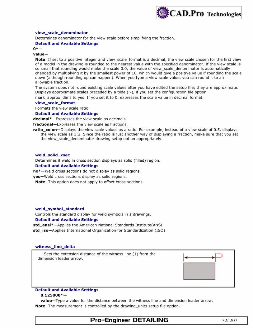
witness_line_delta
Sets the extension distance of the witness line (1) from the dimension leader arrow.
Default and Available Settings
0.125000*— value—Type a value for the distance between the witness line and dimension leader arrow.
Note: The measurement is controlled by the drawing_units setup file option.
Pro-Engineer DETAILING 33/ 207
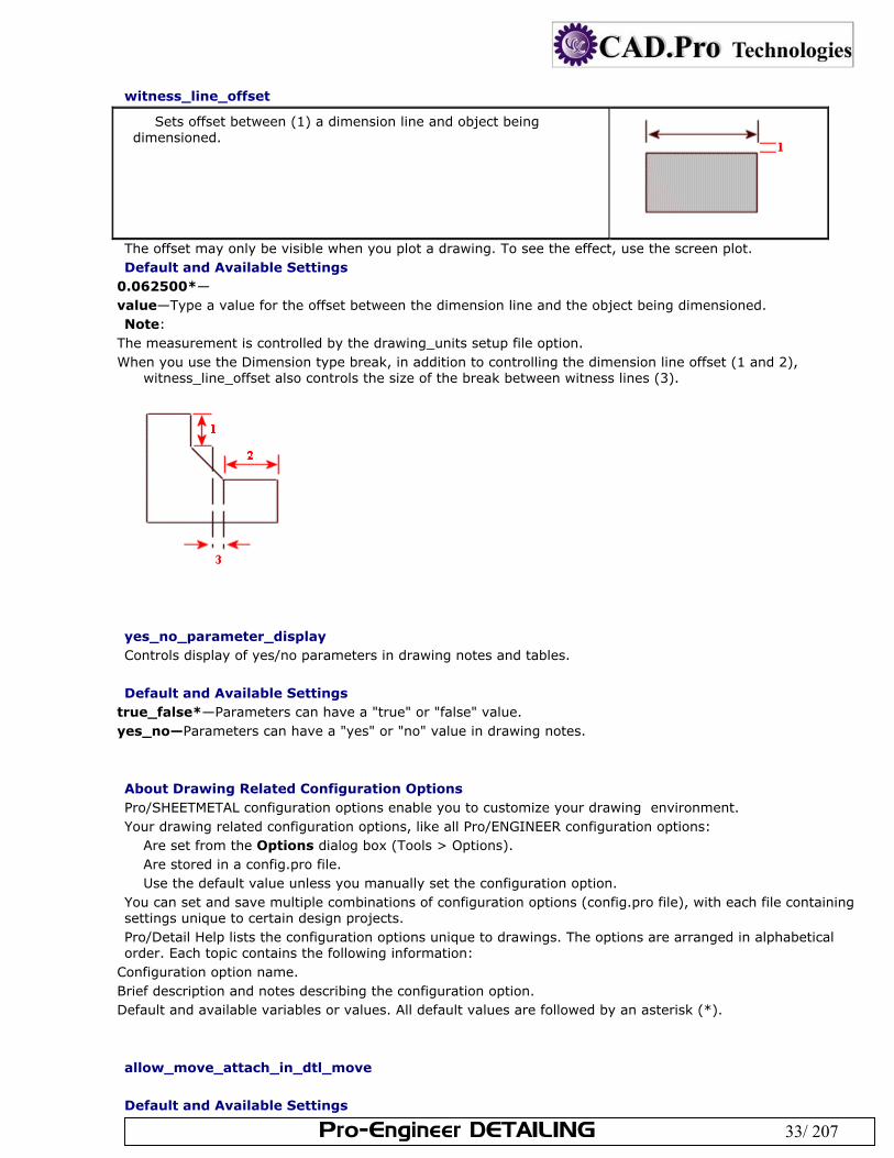
witness_line_offset
Sets offset between (1) a dimension line and object being dimensioned.
The offset may only be visible when you plot a drawing. To see the effect, use the screen plot. Default and Available Settings
0.062500*— value—Type a value for the offset between the dimension line and the object being dimensioned. Note:
The measurement is controlled by the drawing_units setup file option. When you use the Dimension type break, in addition to controlling the dimension line offset (1 and 2),
witness_line_offset also controls the size of the break between witness lines (3).
yes_no_parameter_display Controls display of yes/no parameters in drawing notes and tables. Default and Available Settings
true_false*—Parameters can have a "true" or "false" value. yes_no—Parameters can have a "yes" or "no" value in drawing notes.
About Drawing Related Configuration Options Pro/SHEETMETAL configuration options enable you to customize your drawing environment. Your drawing related configuration options, like all Pro/ENGINEER configuration options:
Are set from the Options dialog box (Tools > Options). Are stored in a config.pro file. Use the default value unless you manually set the configuration option.
You can set and save multiple combinations of configuration options (config.pro file), with each file containing settings unique to certain design projects. Pro/Detail Help lists the configuration options unique to drawings. The options are arranged in alphabetical order. Each topic contains the following information:
Configuration option name. Brief description and notes describing the configuration option. Default and available variables or values. All default values are followed by an asterisk (*).
allow_move_attach_in_dtl_move Default and Available Settings
Pro-Engineer DETAILING 34/ 207
no*—Move and Move Attach commands do not work together. yes—Move and Move Attach commands in drawing mode act together.
allow_move_view_with_move Default and Available Settings
no—Locks all views from mouse movement. yes—
auto_constr_offset_tolerance Sets the auto constraint tolerance for creating offset dimensions. If distance is less than this tolerance multiplied by component size, offset is set as coincident. Default and Available Settings
default—Default value is 0.5 . value—
allow_refs_to_geom_reps_in_drws (not in file) Defaults and Available Options
Yes – Lets you create drawing references to geometry representations.
auto_regen_views Note: When you regenerate a parent view, its child views do not automatically regenerate; you must individually select each view on the drawing, including detail views. Whenever you save changes to the model, the system displays them on the drawing the next time that you retrieve it, regardless of whether you regenerated the drawing views. Default and Available Settings
yes*—Automatically repaints the display when changing from one window to another. The system automatically updates the drawing display by a repaint when you change from one window to another. For example, when you modify a model in a subwindow while you are working on a drawing in the main window. You can repaint or regenerate the drawing to reflect changes made to the model. When you regenerate it, the system updates the model to reflect the changes made in the drawing.
no—Update the drawing, do not repaint the window. You can update only the drawing by choosing Update from the View menu, and then selecting Drawing Views, Current Sheet, or All Sheets. Neither the Update command in the View menu nor the Regenerate command in the Edit menu updates the drawing when you have this option set to no, even if you make the change to the model in Drawing mode (such as modifying a dimension value). You can select as many views as you want to regenerate at the same time. If you try to modify a view that you have not updated, Pro/E displays an error message that it is not going to make changes to the drawing until you apply the Update or Regenerate command to the view.
bom_format Default and Available Settings Enter name and path for BOM format file
chamfer_45deg_dim_text Controls the display of chamfer dimension text without affecting the leader. This only affects the text of newly created dimensions. ASME/ANSI is the default. Default and Available Settings
asme/ansi— iso/din— jis—
Pro-Engineer DETAILING 35/ 207
create_drawing_dims_only Designates where to save new dimensions created within the drawing. Default and Available Settings
yes—Save all new dimensions created in the drawing inside the drawing as associative draft dimensions. no*—Save all dimensions created in drawing mode in the part. Note: When set to yes, this configuration option works in conjunction with the draw_model_read_only configuration option. def_layer Specifies default layer names for different types of items. The first value string is the layer type. The second value string is the layer name. For example, layer_dim_my_layer. Defaults and Available Settings <option name>_<layer name> The following settings are related to default layers for drawings:
layer_assem_member layer_assy_cut_feat layer_axis layer_chamfer_feat layer_comp_design_model layer_comp_fixture layer_comp_workpiece layer_copy_geom_feat layer_corn_chamf_feat layer_cosm_round_feat layer_cosm_sketch layer_csys layer_curve layer_curve_ent layer_cut_feat layer_datum layer_datum_plane layer_datum_point layer_detail_item layer_dgm_conn_comp layer_dgm_highway layer_dgm_rail layer_dgm_wire layer_dim layer_draft_constr layer_draft_dim layer_draft_dtm layer_draft_entity layer_draft_feat layer_draft_geom layer_draft_grp layer_draft_hidden layer_draft_others layer_draft_refdim layer_driven_dim layer_dwg_table layer_ext_copy_geom_feat layer_feature layer_geom_fea layer_gto
Pro-Engineer DETAILING 36/ 207
layer_hole_feat layer_nogeom_feat layer_note layer_parameter_dim layer_part_refdim layer_point layer_protrusion_feat layer_quilt layer_refdim layer_ribbon_feat layer_rib_feat layer_round_feat layer_sfin layer_shell_feat layer_skeleton_model layer_slot_feat layer_snap_line layer_solid_geom layer_surface layer_symbol layer_thread_feat layer_trim_line_feat layer_weld_feat
default_ang_dec_places Specifies the number of decimal places shown in angular dimensions in a drawing. Default and Available Settings Type a value for the number of decimal places shown. The default is 1.
default_draw_scale Sets the default drawing scale for views added with the No Scale command. The value must be greater than 0. Default and Available Settings
yes— no—The system does not set a default drawing scale.
disp_trimetric_dwg_mode_view Displays the model in default orientation when placing a general view. Default and Available Settings
yes— no—Mmodel does not appear until an orientation is chosen from the Orientation dialog box.
display_dwg_sketch_constraint Defaults and Available Settings
yes—Parametric sketching constraints, such as V for vertical, are displayed when a drawing object is selected
display_dwg_tol_tags Sets the display of tolerance tags in drawings. Does not control tolerances on dimensions.
Pro-Engineer DETAILING 37/ 207
display_in_adding_view Controls model display when auto_regen_views is no. Defaults and Available Settings
Default—Displays using the environment setting. Wireframe—Adds new views in wireframes, displays datums. Minimal_wireframe–Displays in wireframe, no datums, axes, or silhouette edges.
draw_models_read_only Determines whether drawing changes results in design changes in the model. Defaults and Available Settings
no*—Drawing model files are not read only; applicable drawing changes result in design changes in the model.
yes—Drawing model files are read-only. You cannot add driven dimensions, geometric tolerances, or similar items to the views.
Note: When set to yes, this configuration option works in conjunction with the create_drawing_dims configuration option. draw_points_in_model_units Defines the current draft views coordinate values as model units rather than drawing units.
drawing_file_editor Specifies the default text editor.
drawing_setup_file Sets the default drawing setup file option values for your Pro/ENGINEER session, otherwise, the system uses the default drawing setup file option values.
drawing_view_origin_csys The named coordinate system will be used as the origin of a newly created view or of a modified view. Defaults and Available Settings
No—The system will not use a previously specified coordinate system.
dwg_select_across_pick_box Defaults and Available Settings
Yes— Highlights the Across Box command by default when the PICK MANY menu appears. No—The Inside Box command highlights.
force_wireframe_in_drawings Defaults and Available Settings
Yes – Displays all views in wireframe. No – displays views according to display set for the session.
format_setup_file Assigns a specified setup file to each drawing format. To assign the drawings parameter values to the format, you must retrieve the drawings setup file into the format.
Pro-Engineer DETAILING 38/ 207
general_undo_stack_limit Limits the number of possible Undo/Redo operations stored in the stack (memory). If the limit is reached, the first operation that was added to the stack will be the first operation removed. Defaults and Available Settings
50*—Limit the undo/redo mechanism to 50 operations. value—Type a maximum storage value for the undo/redo operation.
harn_tang_line_display Display the tangency lines between cables in thick cable display mode. Defaults and Available Settings
yes*—Displays the tangency lines for thick cables. no—Does not display the tangency lines for thick cables.
highlight_erased_dwg_views Controls the display of erased view outlines (environment option Highlight Erased Views.) Defaults and Available Settings
No – turns off highlighting for erased views.
highlight_new_dims In Drawing mode, highlights new dimensions in red until you move them or repaint the screen.
hlr_for_quilts Controls quilt display in hidden line removal. Defaults and Available Settings
Yes—Includes quilts in hidden line removal process.
iges_in_dwg_line_font Pro/ENGINEER processes the IGES line font definition entity (type 304, form 2) when you set these options to yes.
iges_out_dwg_line_font Pro/ENGINEER processes the IGES line font definition entity (type 304, form 2) when you set these options to yes.
make_parameters_from_fmt_tables Determines the handling of values entered in a format table when you replace one drawing format with another. Defaults and Available Settings
Yes—Stores entered values for format table and copies them with the table. No—Prompts you to re-enter all the values for the format table.
make_proj_view_notes Automatically adds view names to projection views in the format You can modify the view name after adding the view to the drawing.
Pro-Engineer DETAILING 39/ 207
pick_chain_tangent_only Specifies the extent of draft entity chains selected. Defaults and Available Settings
Yes – Only entities in the chain that are tangent will be selected. No – All entities connected end to end will be selected.
pro_dtl_setup_dir Set the directory for he drawing setup files.
pro_format_dir Sets the default directory for the drawing format library. Use the full pathname to avoid problems.
pro_note_dir Specifies the directory from which to retrieve notes entered from a file. Use the full path name to avoid problems.
pro_palette_dir Sets the default directory for drawing symbol palette files.
pro_symbol_dir Set and automatically create the default directory for saving and retrieving user-defined symbols. If you do not specify a directory, the system uses the current working directory. Use full path name to avoid problems.
remember_last_get_point_option Sets the default of the Get Point menu as the last option picked among Pick Pnt, Vertex, and On Entity.
rename_drawings_with_object Creates a copy of the associated drawing when you use File > Save a Copy to copy a model. The new drawing adopts the new part filename. Defaults and Available Settings
part assembly both
save_display Determines whether to store view geometry and detail items such as solid dimensions in the View-Only mode. Defaults and Available Settings
no*—Does not display geometry and detail items in View-Only mode. yes—Stores view geometry and detail items such as solid dimensions. These items are displayed when
retrieving the drawing in View-Only mode. Note: You can change this setting at run time: click Utilities > Environment, and then click or clear Save Display under Default Actions in the Environment dialog box. save_drawing_picture_file Defaults and Available Settings
Embed - Embeds a picture file inside a drawing for preview purposes.
Pro-Engineer DETAILING 40/ 207
Export - Saves a drawing file as a picture file in the working directory when saving a drawing. Both - Does both embed and export.
save_modified_draw_models_only Determines whether the system saves the model after you have changed it. Defaults and Available Settings
No - Saves the model every time that you store the drawing.
selection_of_removed_entities Defaults and Available Settings
Yes – Entities in front of cross section (planar or offset) can be selected, clipped (using Z-clipping) or erased using edge disp menu. No – Geometry, datum points or curves, cosmetic features, threads, grooves, or co ordinate systems cannot be erased.
switch_dims_for_notes Defaults and Available Settings
yes—Dimensions are displayed in their symbolic format during drawing note creation. no—Dimensions use numeric values.
symbol_instance_palette_file Specifies the location of the symbol instance palette.
symbol_palette_input Controls the display of the special symbol palette during note creation.
todays_date_note_format Controls the initial format of the date displayed in a drawing. The format for the setting is a string consisting of three portions: the year, the month, and the date. You can enter the portions in any order.
variant_drawing_item_sizes Defaults and Available Settings
No - Drawing items moved/copied to a different sheet or located on a changed sheet keep same size and relative orientation on paper.
Yes - Some items scale/reposition to be the same on paper, and others scale and/or reposition to be the same on screen.
About Drawing Templates Drawing templates may be referenced when creating a new drawing. They automatically create the views, set the desired view display, create snap lines, and show model dimensions based on the template. Drawing templates contain three basic types of information for creating new drawings. The first type is basic information that makes up a drawing but is not dependent on the drawing model, such as notes, symbols, and so forth. This information is copied from the template into the new drawing. The second type is instructions used to configure drawing views and the actions that are performed on that view. The instructions are used to build a new drawing with a new drawing object (model). The third type is parametric notes. Parametric notes are notes that update to new drawing model parameters and dimension values. The notes are re-parsed or updated when the template is instantiated.
Pro-Engineer DETAILING 41/ 207
Use the templates to: Define the layout of views Set view display Place notes Place symbols Define tables Create snap lines Show dimensions
You can also create customized drawing templates for the different types of drawings that you create. For example, you can create a template for a machined part versus a cast part. The machined part template could define the views that are typically placed for a drawing of a machined part, set the view display of each view (for example, show hidden lines), place company standard machining notes, and automatically create snap lines for placing dimensions. Creating a template allows you to create portions of drawings automatically, using the customizable template. To Create a Drawing Template Click File > New. The New dialog box opens. Click Drawing, and then type the name of the template you are creating or accept the default. Select the Use default template checkbox (selected by default), and then click OK. The New Drawing
dialog box opens. Click Empty or Empty with format.
If you click Empty with format: Under Format, specify the format you want to use. Then click OK. Pro/ENGINEER creates a new drawing with the specified format. If you click Empty: Under Orientation, specify the template orientation by clicking Portrait, Landscape, or Variable. For Portrait or Landscape, choose a standard size under Size. For Variable, specify a size using the Width and Height boxes, and specify a unit by selecting Inches or Millimeters.
Click OK to create the template. Click Applications > Template to enter drawing template mode Click Insert > Template View. The Template View Instructions dialog box opens. Type the view name or accept the default, and then specify the view orientation. In the Model "Saved View" Name text box, orient the view. Specify view options and view values in the View Options and View Values areas. Click Place View and select the location of the General view.
Note: After you place the view, you now have the options to move the symbol, edit the view symbol, or to replace the view symbol.
To place additional views, click New, type the new view name, and orient the new view. Specify the view options and view values of the new view.
When you are done placing all of the desired views, click OK. Save the template. To Create a Drawing Using a Drawing Template Click File > New. The New dialog box opens. Click Drawing, and then type the file name for the drawing you are creating or accept the default name. Clear the Use default template checkbox, and then click OK. The New Drawing dialog box opens. Select the model from which you want to create the drawing. Specify the template by clicking Use template. Type the name of the template you want to use or select a
template from the Template list. Click OK. The drawing is created. Note: The views with the correct attributes in both the template and the model are created. If attributes that are defined in the template do not exist in the model, errors occur when the drawing is being created. The Drawing Template Error Info dialog box opens and lists the errors. To access the Drawing Template Error Info dialog box, click Info > Template Errors. The Template View Instructions Dialog Box The Template View Instructions dialog box is accessed from the TMPLT DWG menu (on the Menu Manager), which appears when you click Application > Template in Drawing mode. For more information about Drawing template mode, click To Create a Drawing Template in Pro/HELP. Use the following options in the Template View Instructions dialog box to customize your drawing templates:
View Name—Set the name of the drawing view that will be used as the view symbol label. View Orientation—Create a General view or a Projection view.
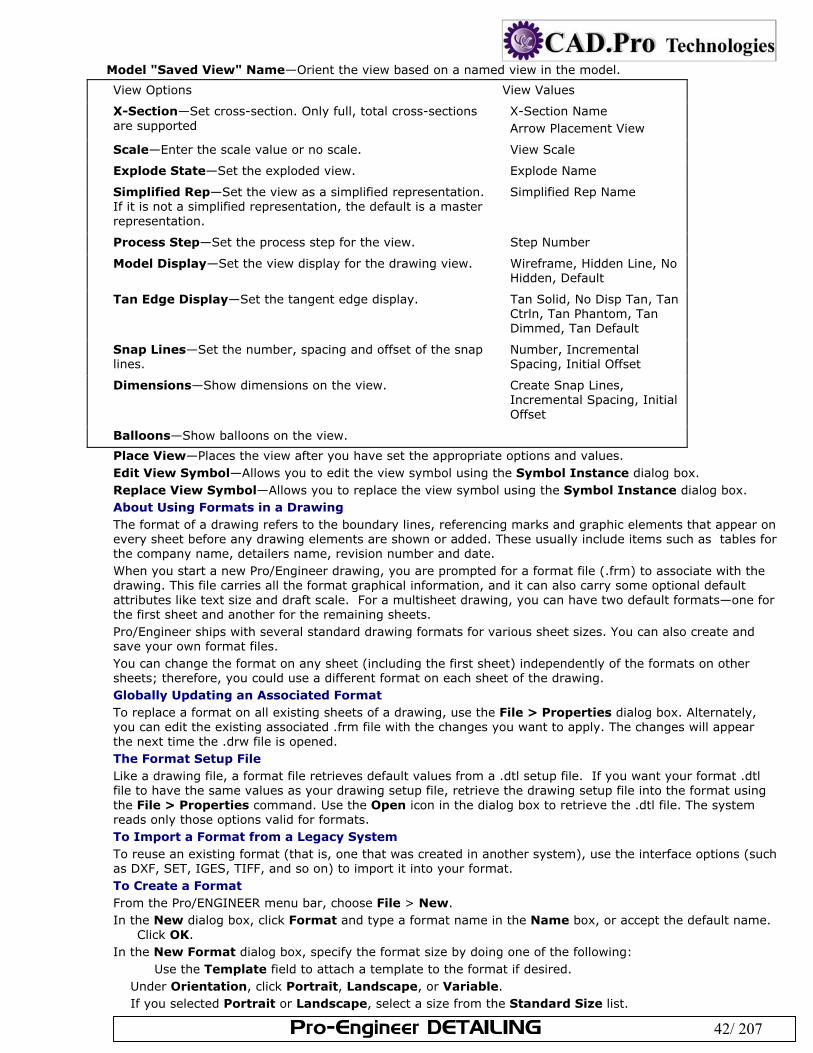
Pro-Engineer DETAILING 42/ 207
Model "Saved View" Name—Orient the view based on a named view in the model.
View Options View Values
X-Section—Set cross-section. Only full, total cross-sections are supported
X-Section Name Arrow Placement View
Scale—Enter the scale value or no scale. View Scale
Explode State—Set the exploded view. Explode Name
Simplified Rep—Set the view as a simplified representation. If it is not a simplified representation, the default is a master representation.
Simplified Rep Name
Process Step—Set the process step for the view. Step Number
Model Display—Set the view display for the drawing view. Wireframe, Hidden Line, No Hidden, Default
Tan Edge Display—Set the tangent edge display. Tan Solid, No Disp Tan, Tan Ctrln, Tan Phantom, Tan Dimmed, Tan Default
Snap Lines—Set the number, spacing and offset of the snap lines.
Number, Incremental Spacing, Initial Offset
Dimensions—Show dimensions on the view. Create Snap Lines, Incremental Spacing, Initial Offset
Balloons—Show balloons on the view.
Place View—Places the view after you have set the appropriate options and values. Edit View Symbol—Allows you to edit the view symbol using the Symbol Instance dialog box. Replace View Symbol—Allows you to replace the view symbol using the Symbol Instance dialog box. About Using Formats in a Drawing The format of a drawing refers to the boundary lines, referencing marks and graphic elements that appear on every sheet before any drawing elements are shown or added. These usually include items such as tables for the company name, detailers name, revision number and date. When you start a new Pro/Engineer drawing, you are prompted for a format file (.frm) to associate with the drawing. This file carries all the format graphical information, and it can also carry some optional default attributes like text size and draft scale. For a multisheet drawing, you can have two default formats—one for the first sheet and another for the remaining sheets. Pro/Engineer ships with several standard drawing formats for various sheet sizes. You can also create and save your own format files. You can change the format on any sheet (including the first sheet) independently of the formats on other sheets; therefore, you could use a different format on each sheet of the drawing. Globally Updating an Associated Format To replace a format on all existing sheets of a drawing, use the File > Properties dialog box. Alternately, you can edit the existing associated .frm file with the changes you want to apply. The changes will appear the next time the .drw file is opened. The Format Setup File Like a drawing file, a format file retrieves default values from a .dtl setup file. If you want your format .dtl file to have the same values as your drawing setup file, retrieve the drawing setup file into the format using the File > Properties command. Use the Open icon in the dialog box to retrieve the .dtl file. The system reads only those options valid for formats. To Import a Format from a Legacy System To reuse an existing format (that is, one that was created in another system), use the interface options (such as DXF, SET, IGES, TIFF, and so on) to import it into your format. To Create a Format From the Pro/ENGINEER menu bar, choose File > New. In the New dialog box, click Format and type a format name in the Name box, or accept the default name.
Click OK. In the New Format dialog box, specify the format size by doing one of the following:
Use the Template field to attach a template to the format if desired. Under Orientation, click Portrait, Landscape, or Variable. If you selected Portrait or Landscape, select a size from the Standard Size list.
Pro-Engineer DETAILING 43/ 207
If you selected Variable, you must define both the height and width dimensions. Select Inches or Millimeters and type values in the Width and Height boxes.
Click OK. The system displays the format as specified, and the FORMAT menu appears. To Create or Modify Format Geometry To create or edit format geometry in a .frm file, use the Sketch menu, or use any of the sketcher icons in the side menu. To modify the values of symbol text, symbol height, and note text in a standard drawing format, use the same commands that are available during format creation. To Change Formats in an Existing Drawing Click File > Page Setup. The Page Setup dialog box opens. Use the drop-down list to the right of each sheet number to assign a format style.
To set a custom size, use the Variable setting in the list box. To load a format not listed, use the Browse setting. To show or hide the format for a specific page, use the Show Format checkbox.
To Hide the Format Click File > Page Setup. In the Page Setup dialog box, clear the Show Format checkbox. Click OK.
Tip: Sheet Outline and Plotting The sheet outline is the border of the standard drawing format you selected. Because it is the actual border, it may not appear on pen plots unless you use a paper size larger than the drawing size. Everything within the sheet outline border is also plotted, but you should make an allowance for the plotter hold-down rollers.
To Match Setup Values in Drawings and Formats Like a drawing file, a format file retrieves default values from a .dtl setup file. If you want your format .dtl file to have the same values as your drawing setup file, you can retrieve the drawing setup file into the format.
With the format file open: Click File > Properties. On the menu manager, click Draw Setup. The Options dialog box opens. Use the File > Open icon to open the target .dtl file. The system reads in only those options valid for
formats. Click OK. About Using Tables in a Format Using the Table command in the FORMAT menu, you can create tables and add them to drawing formats. Then, when you add a format to a drawing, Pro/ENGINEER copies all of the tables in the format into the drawing. The copied tables are independent of the original format, and you can move, modify, or delete them. When you add, replace or remove a format, (using File > Page Setup), the system highlights the table copied from the old format and asks if it should remove it. You can choose one of the following: (Y)es, (N)o, (K)eep all, (R)emove all. If you add a table to a format, the drawings that already reference this format do not display the new table. The table must be part of the format when you initially copy it into the drawings. To use the modified format in the drawing, you must use the replace function. When you add a format to a drawing that contains the format table, the system stores the values you specified for the table as drawing parameters, if you have set the configuration file option make_parameters_from_fmt_tables to yes. You can access the parameters using the Tools > Parameters and Relations command. If you set this configuration option to no, when you add a format to a drawing, the system prompts you to retype all of the values every time, and it does not evaluate the values on subsequent sheets of the drawing in the format table. These values are nonparametric text. For the system to reprompt you for the parameter text, you must use the Add or Replace commands. Note: You cannot use reserved model parameters. If you set make_parameters_from_fmt_tables to yes in the configuration file, Pro/ENGINEER does not prompt you to type a value for reserved model parameters because it cannot add them to the drawing.
Pro-Engineer DETAILING 44/ 207
If you change the format size of a drawing with a table, the system scales the table (in the same way that it scales any views and draft entities) to maintain its location relative to other items and the sheet boundaries. Since the drawing setup file option drawing_text_height controls the height of any text in the table, Pro/ENGINEER does not scale text that you include in the table. Therefore, it does not maintain a size that is proportional to the rest of the table. You must modify the text height manually. About Notes in Formats and Tables When you place a parametric note in a format, the note in the format acquires the appropriate value when you use it in a drawing. For example, if you create the note &model_name in a format, the system displays the actual model name in the note. For the system to update these parameters when you add the format to a drawing, you can include in parametric notes only the drawing labels listed in the topic titled System Parameters for Drawings (except &todays_date). You must include all user-defined model and drawing parameters in format table cells in the form of ¶m in order for the system to update them in a drawing. Format mode interprets the following types of parametric notes:
Notes with symbol instances Notes with standard system symbols Notes with drawing labels Notes with a default tolerance
The following rules apply to including parameters as labels in format tables: Pro/ENGINEER correctly evaluates parametric labels that you include in a format table only if you create the
drawing first, add the model, and then add the format. It does not evaluate the labels correctly if you create the drawing, add the format, and then add the model.
When you add a format to a drawing with more than one model present, parametric notes can reference only the active drawing model.
When you add the format to a drawing, Pro/ENGINEER parses any and all that are present of the standard parametric symbols that it supports and displays the correct values in the table. It does this for every sheet of the drawing on which you use the format, so that the drawing name, model name, or any other standard parameter that you used appears on every sheet that uses that format.
To Add a Table to a Format Using the Table command in the FORMAT menu, you can include tables in drawing formats. When you add a format to a drawing, Pro/ENGINEER copies all of the tables in the format into the drawing. After it copies them, the tables are independent of the original format, and you can move, modify, or delete them. Make sure that the format file to which you want to add a table is the active file. On the FORMAT menu, click Table > Insert > Table. The Table Create menu opens on the Menu Manager. Click from the following options:
Descending or Ascending—Lets you choose the direction in which to create rows from the starting point. Rightward or Leftward—Lets you choose the direction in which to add columns from the starting point. By Num Chars or By Length—Lets you define the length of columns and rows using drawing units (such
as inches or millimeters) or by specifying the number of characters as the unit. Use the options on the GET POINT menu to locate the starting corner of the table on the format. The starting
corner depends on the choices you made in the preceding step. Pick Pnt—Lets you select a point on the format and specify it as the starting corner. Vertex—Lets you select a vertex and specify it as the starting corner. On Entity—Lets you select an entity on the format and specify it as the starting corner. Rel Coords—Lets you specify relative coordinate values for placing the starting corner by entering relative
values for the X- and Y-Axes. Abs Coords—Lets you specify absolute coordinate values for placing the starting corner by entering
absolute values for the X- and Y-Axes. At the prompt, enter the width of the first column in drawing units, and then press ENTER. Continue entering the width of additional columns until you have the number of columns you want. Then
press ENTER again without typing another column width value. At the prompt, enter the height of the first row in drawing units, and then press ENTER. Continue entering values for the height of additional rows until you have the number of rows you want. Then
press ENTER again without typing another row height value. The table displays on the format sheet. To Use Parameters in Labels in a Format Table You can include parametric labels, such as the drawing name, model name, and sheet number, as text in a format table. For a multimodel drawing, you can type into the format table any parameters related to both the first model and the second model. To include the parametric labels in the table:
Pro-Engineer DETAILING 45/ 207
Double click the table cell where you want to place the label text. In the Enter Text dialog box, enter the appropriate label (such as &dwg_name). When you are done click
OK. The label appears in the table exactly as you typed it until you add the format to a drawing. To Set Up a Format Library Use the configuration option pro_format_dir to set a path name (directory) where your company formats will be stored. When you use this configuration option, Pro/ENGINEER automatically searches the specified directory for company formats when adding or replacing formats in your drawing and layout. Pro/ENGINEER places modified formats in this directory when you save them. Click Tools > Options. The Options dialog box opens. Enter the configuration file option pro_format_dir. This option uses a path name (directory) as its value, so
you can create a single set of formats that everyone on the system can use, and place them all in a single directory.
Under Value, enter the path name and directory where you want to store all formats. To Retrieve a Format from the Format Library Using the File Open dialog box, you can retrieve formats from a format library directory within Pro/ENGINEER. To retrieve a format: Click File > Open. The File Open dialog box opens. Select System Formats from the Look In list. Navigate the menu tree until you locate the format. Click Open. The selected format opens. To Create a Drawing When you start a new drawing, you specify a 3D model file for which to place drafting views. Click File > New. In the New dialog box, click Drawing and type a drawing name in the Name box (or use the default); then
click OK. The New Drawing dialog box opens. In the Default Model box, type the name of a model in the working directory. If you started the new file
from an open 3D file, the 3D filename is entered by default. Under Specify Template, do one of the following:
To use a Pro/ENGINEER drawing template, click Use Template, and then select a template from the list. To create a drawing without a template but with an existing format, click Empty with format. Under
Format, specify the format you want to use. Specify the drawing size or retrieve a format. To specify the size, do one of the following:
Click Portrait or Landscape in the Orientation box and select a standard size from the Standard Size list. Portrait makes the height larger than the width, and Landscape makes the width larger than the height.
Or Click Variable in the Orientation box to define both the height and width dimensions. Select Inches or Millimeters and type values in the Width and Height boxes. To retrieve a format, select Retrieve Format and select a name from the Name list in the Format box. You can also type [?] or click Browse to select a name from the Open dialog box.
Click OK. The system displays the new drawing. To Add Models to the Drawing Before you can place a view of a 3D model, you must associate the 3D model file with the drawing. This is called adding the model to the drawing. When you start a new drawing file you are prompted in the New File dialog box for a 3D model file to reference. Once the drawing is in progress, to add other models to the drawing file: Click File > Properties. The Menu Manager opens. In the Menu Manager click File Properties > Dwg Models > Add Model. A file browser opens. Use the browser to select the model you want to add to the list of models associated with the drawing. Adding a model to the drawing does not place a view of the model on the sheet, but it lets the drawing reference the model so that you can place a view.
To Set the Current Working Model If a drawing has more than one model added to it, one of the models is always the current working model. Use this procedure to switch current status from one model to another. Click File > Properties. The Menu Manager opens and displays the File Properties menu. In the Menu Manager click Dwg Models > Set Model. The Draw Model menu opens. Select the model from the namelist menu. It contains only model names that you have added to the drawing.
Pro-Engineer DETAILING 46/ 207
Alternately, you can set the active model using the Set Model drop down list, found on the toolbar. Note:
To highlight the current active model, choose File > Properties > Dwg Models > Model Disp > Hilite Cur.
To return the model display back to normal, choose Model Disp > Normal.
To Replace Models from Family Tables If a model that you use in a drawing is a member of a family table, you can replace that model with other family table members. The system maintains dimensions, attached notes, and other drawing annotations when one model replaces another. Use the Select Instance dialog box to select an instance with which to replace the model. Click File > Properties. The Menu Manager opens. In the Menu Manager click File Properties > Dwg Models > Replace. Select the model that you want to replace as the active model. The Select Instance dialog box opens when
you are replacing the model of one family table instance with another. Select the name of another family member to replace it. The Select Instance dialog box displays a list of all instances of the currently selected family table model.
You can select one of these to use as the replacement model. You can select an instance by name when the By Name page is visible (the default), or click the By Parameter tab to select an instance by parameter.
After selecting an instance to be the replacement, click Open. The current model is replaced by the selected instance. Note: When you are using automatic replacement, if the system shows dimensions in the assembly drawing on a component that you have replaced with the new instance, it displays equivalent dimensions. However, if you replace the component using manual replacement, it does not preserve the dimensions.
If a model that you use in a drawing is a member of a family of parts or assemblies, you can replace that model with other family members. The system maintains dimensions, attached notes, and other drawing annotations when one model replaces another. To Open a Model from a Drawing To open a model from within Drawing mode, you can use File > Open, or you can use the Model Tree. Click File > Open. The File Open dialog box opens. Navigate to and select the model you want to open, and then click Open. The model is retrieved into the current session in a separate Pro/ENGINEER window. Using the Model Tree In the Model Tree, select the model you want to retrieve, and then right-click to display the shortcut menu. Click Open from the shortcut menu. The model is retrieved into the current session. Sheets and Multiple Windows You can:
show multiple sheets in multiple windows show the same sheet in multiple windows create a new sheet in a new window To create a new sheet in a new window: Click Window > New. At the prompt, type the sheet number to appear in the new window, and then press ENTER. You can also add
a new sheet to the drawing. The new window appears with the specified sheet.
About Assembly Drawings In an assembly drawing, you can show and erase assembly and part dimensions. You can also create dimensions on individual components directly in an assembly view. However, keep in mind the following:
You can display parameters for assembly features and all assembly components in assembly drawing notes, but you cannot type part parameters.
The dimensions in an assembly drawing are visible for modification only if the assembly for which the drawing was created is in session.
Pro-Engineer DETAILING 47/ 207
Resuming Cosmetics When you suppress parts or subassemblies in an assembly drawing, the system retains information about certain cosmetics of these views. When you resume them, you also resume these cosmetics:
Dimension placement Surface finish symbol placement Parametric text in notes and symbol instances Cross-hatching cosmetics References to cross-sectional edges Detail axis cosmetics Member, edge, and set datum display information Draft geometric tolerances that reference part datums
About Multisheet Drawings You can create multiple sheet drawings and move items from one sheet to another. When working with multisheet drawings, keep in mind the following:
You can switch a projection view to another sheet, but it will lose its association with its parent view. If you switch the projection view back to the same sheet as the parent, the association is restored.
You can change drawing scales on each sheet independently.
To Add or Delete Sheets To add a sheet, click Insert > Sheets. Pro/ENGINEER adds a new sheet to the end of the drawing. To delete a sheet, Click Edit > Remove > Sheet. Enter the sheet numbers of the sheets you want to remove. You can separate them by using commas or dashes and insert spaces anywhere, for example, [1,3-5,12,15-20]. The number to the left of a dash must always be less than the number to the right. Press Enter.. To Reorder the Sheets in a Drawing Click Edit > Move Sheet. Use the dialog box to insert the current sheet within the sheet numbers.
Note: If there is a process assembly in the drawing, the command is Edit > Move or Copy Sheet. There is an additional checkbox called 'Copy process sheet.' When checked, the Process State dialog box opens and prompts you to select a step. Select OK to close the dialog box and insert the copied process sheet at the location specified in the list.
To Move Items to Another Sheet Select the item or items to move. Click Edit > Move Item to Sheet . You are prompted to enter the target sheet number. Enter the target sheet number on the prompt line. Press Enter. The items are moved to the new sheet. Maintaining View Size with Sheet Size When moving items from one sheet to another in a drawing, use the configuration file option variant_drawing_item_sizes to control whether drawing items maintain their size and position on paper if you change the sheet size or drawing units.
If you set this option to yes, some items scale and/or reposition to be the same size or in the same place when you plot them on paper, while other items scale and/or position themselves to be the same size or in the same place on screen.
If you set it to no, items that you move or copy to a different sheet of the same or different 2-D model (or items on a sheet that changes size and/or units) retain the same size on paper and the same relative orientation as they did previously.
About Drawing Changes and Model Revision As you detail your drawing, some drawing entities and information are parametrically associated to the model that it documents. Therefore, changes made within the drawing could result in design changes within the model.
Pro-Engineer DETAILING 48/ 207
For example, if you set a dimension as basic within a drawing, the dimension becomes theoretically exact. Any dimensional or geometric tolerances are deleted from the drawing as well as the from the 3D model. The design changes in the model result from changes to drawing entities that are saved within the model; including all dimensions, tolerances, cross-sections, and model datums. After creating or modifying any of these drawing entities within a drawing, they are saved with the model and increase the model revision number. You can designate how to create drawing dimensions and how the model is affected using the create_drawing_dims and drawing_model_read_only configuration options. The following drawing entities are considered cosmetic information and are saved within the drawing:
All draft-only (non-associative) entities The view in which an entity appears The placement of an entity on the sheet Jogs and breaks in leaders and dimension lines The insertion of dimensions in notes The font, height, width, and slant angle of text The following drawing entities are saved within the model and result in a new model iteration:
Geometric tolerances (you can also save them in the drawing) Dimension information (also reference and driven dimensions), including the following:
Additional text Standard/ordinate dimension type Attached geometric tolerance list Attached set datum or axis reference Value and tolerance information The difference between the primary and secondary units, when you have explicitly set them Basic and inspection attributes Set datum and axis information Datum target point information Surface finishes, including type and value Simplifications (using By View and All Views) Layer membership information for all entities in the model
To Refresh the Connection to the 3D Model Most drawing objects are updated dynamically as changes are made in the 3D associated model file. For a variety of reasons some objects may not refresh until you force a regeneration between the model and the drawing. If you see objects in the drawing that should be updating but are not, use View > Update and one of the options below to refresh the model-drawing association:
Drawing View—Updates a particular view with any recent model changes. Current Sheet—Updates all the views on the current sheet with any recent model changes. All Sheets—Updates all the views on all the sheets contained in the drawing, displaying any recent model
changes. Regenerating the Model from the Drawing If graphics are not updating in the drawing, you may need to force a regeneration of the model. You can do this from the drawing, without opening the model file. There are two levels available for this process.
Edit > Regenerate > Draft. Updates all values from the 3D model, but does not physically regenerate the 3D model, and does not refresh the geometry in the drawings. This can help performance in updating symbols or GTOLS without a complete refresh of the drawing. Drawing dimensions that have changed in the model but that have not been regenerated are displayed in a different color.
Edit > Regenerate > Model. Completely refreshes the model-drawing association. Pro/Engineer first regenerates the model, then refreshes the geometry in the drawing. When you use this command, the PRT TO REGN menu opens on the Menu Manager. You have options concerning the extent of the regeneration you want to do. Use one of the options depending on the size of the file you are working with or the speed of your PCs performance: Select - Select a part or parts to regenerate. You can select multiple parts from the model tree, and click Done in the Menu Manager when you are finished. Automatic - Update all parts that have been edited in the 3D model since the last update.
To Open a 3D File from the Model Tree You can quickly open any associated 3D file directly from the model tree. Select the model in the model tree. Right-click and click Open from the shortcut menu. The 3D Model is opened in a new window.
Pro-Engineer DETAILING 49/ 207
To Show a Referenced Part in the Model Tree The drawing model tree displays one part and its features at one time. If more that one part is added to the drawing, use this procedure to change the part displayed in the model tree.
In the navigation window, click Show > Use Model in Tree. A selection prompt window opens. Select a view representing the part you want to show in the model tree. Click OK in the selection window. The new part is displayed in the model tree.
To Turn Off Automatic Regeneration By default, the display is updated with a repaint when you change from one window to another. Because model-to-drawing repaints and regenerations can be time consuming for larger files, you have the option to turn off the automatic regeneration function. If you set auto_regen_views to no, you can selectively update the drawing by choosing View > Update from the menu. With this setting, you can only update the drawing to reflect changes in the 3D model, you cannot regenerate the model from the drawing as you can with the yes setting. To Save Associated Models on Edit Only By default, when you save a drawing, Pro/ENGINEER saves all associated models regardless of whether they were edited. This will update the file date, and may cause unwanted results in a file version-control situation. If you want to save the associated model files only when they are affected by drawing changes, set the configuration file option save_modified_draw_models_only to yes. To Disallow Changes Affecting the Model To disallow changes made in Drawing mode that affect associated 3D models, set the configuration file option draw_models_read_only to yes. In this case, when you attempt to make a change that affects the model, Pro/ENGINEER issues a warning and does not make the modification. About Working with Drawing Views Once a model has been added to the drawing, you can place views of the model on a sheet. When a view is displayed on the drawing, you can determine how much of the model to show in a view, whether the view is of a single surface or shows cross sections, and how the view is scaled. You can then show the associative dimensions passed from the 3D model, or add reference dimensions as necessary. Working with model views involves:
Specifying the view types, such as general, projection, and detailed. Determining a location for the view on the drawing. Defining the drawing views; including determining visible areas, scaling, defining cross-sections, showing the
model in various states, and aligning and setting the view origins. Moving and deleting views. Inserting Drawing Views Before you can place a view of a 3D model, you must associate the 3D model file with the drawing. This is called adding the model to the drawing. When you start a new drawing file you are prompted in the New File dialog box for a 3D model file to reference. This will be the first model associated with the drawing. Once the drawing is in progress, you can add as many more models as you need to place views for. If you have several models added to the drawing, you can only work on (place views and show dimensions for, etc.) one model at a time. This model is called the current active model. Generally, placing a new view is a process of specifying the view type, the properties the particular type can have, and then choosing a location on the sheet for the view. Finally, the view is placed and you set the desired orientation for it. Note: To move a view after it is placed, be sure the Lock View Movement check box is un-checked in the Tools > Environment dialog box. Or right-click on a blank section of the drawing and unlock the view using the shortcut menu. To Insert a General View A general view is usually the first view placed on a sheet. It is the most versatile view in that it can be scaled or rotated to any setting. Click Insert > Drawing View > General. Select a location on the screen to place the general view. The general view appears and the Drawing View
dialog box opens. By default, the View Type category is selected and the options for defining the view type and orientation display.
Under View Type, you can modify the view name, however, if a general view has not yet been displayed, you can not change the view type.
Position the general view on the drawing by selecting an orientation method and then defining the orientation requirements:
View names from the model—Orient using saved views from the model.
Pro-Engineer DETAILING 50/ 207
Select the appropriate model view from the Model view names list. Define the x and y orientation by selecting the desired Default orientation. You can select either Isometric, Trimetric, or User Defined; in which case you type in custom angle values.
Geometry references—Orient using geometry references from the previewed model in the drawing. Select the direction to orient the reference from the list next to the reference being defined. The list
provides several options, including Front, Back, Top, and Bottom. Select the desired reference on the model previewed on the drawing. The model repositions according to
the direction defined and the references selected. You can change the orientation by selecting another direction option from the direction list, and you can change the selected reference by clicking the reference collector and selecting a new reference on the drawing model. Note: To return the view to its original orientation, click Default Orientation.
Angles—Orient using angles of selected references or custom angles. The Reference Angle table lists the references used to orient the view. By default, a new reference is added to the list and highlighted. Select the desired Reference rotation option for the highlighted reference in the table:
Normal—Rotate the model around an axis through the view origin and normal to the drawing sheet. Vertical—Rotate the model around an axis through the view origin and vertical to the drawing sheet. Horizontal—Rotate the model around an axis through the view origin and horizontal to the drawing sheet. Edge/Axis—Rotate the model around an axis through the view origin and according to the designated angle to the drawing sheet. Select an appropriate edge or axis reference on the previewed drawing view. The selected reference highlights and is listed in the Reference Angle table.
Type an angle value for the reference in the Angle Value box. Note: To create additional references, click and repeat the angle orientation process.
To continue defining other attributes of the drawing view, click Apply and then select the appropriate category. If you have completely defined the drawing view, click Ok.
Note: If you delete or suppress geometry that the system is using to orient a view, it changes that view and all of its children to the default orientation. You cannot recover the original view orientation if the geometry was deleted. Resuming the suppressed feature, however, restores the original orientation of the view. Inserting Drawing Views Before you can place a view of a 3D model, you must associate the 3D model file with the drawing. This is called adding the model to the drawing. When you start a new drawing file you are prompted in the New File dialog box for a 3D model file to reference. This will be the first model associated with the drawing. Once the drawing is in progress, you can add as many more models as you need to place views for. If you have several models added to the drawing, you can only work on (place views and show dimensions for, etc.) one model at a time. This model is called the current active model. Generally, placing a new view is a process of specifying the view type, the properties the particular type can have, and then choosing a location on the sheet for the view. Finally, the view is placed and you set the desired orientation for it. Note: To move a view after it is placed, be sure the Lock View Movement check box is un-checked in the Tools > Environment dialog box. Or right-click on a blank section of the drawing and unlock the view using the shortcut menu. To Insert a General View A general view is usually the first view placed on a sheet. It is the most versatile view in that it can be scaled or rotated to any setting. Click Insert > Drawing View > General. Select a location on the screen to place the general view. The general view appears and the Drawing View
dialog box opens. By default, the View Type category is selected and the options for defining the view type and orientation display.
Under View Type, you can modify the view name, however, if a general view has not yet been displayed, you can not change the view type.
Position the general view on the drawing by selecting an orientation method and then defining the orientation requirements:
View names from the model—Orient using saved views from the model.
Pro-Engineer DETAILING 51/ 207
Select the appropriate model view from the Model view names list. Define the x and y orientation by selecting the desired Default orientation. You can select either
Isometric, Trimetric, or User Defined; in which case you type in custom angle values. Geometry references—Orient using geometry references from the previewed model in the drawing. Select the direction to orient the reference from the list next to the reference being defined. The list
provides several options, including Front, Back, Top, and Bottom. Select the desired reference on the model previewed on the drawing. The model repositions according to
the direction defined and the references selected. You can change the orientation by selecting another direction option from the direction list, and you can change the selected reference by clicking the reference collector and selecting a new reference on the drawing model. Note: To return the view to its original orientation, click Default Orientation.
Angles—Orient using angles of selected references or custom angles. The Reference Angle table lists the references used to orient the view. By default, a new reference is
added to the list and highlighted. Select the desired Reference rotation option for the highlighted reference in the table:
Normal—Rotate the model around an axis through the view origin and normal to the drawing sheet. Vertical—Rotate the model around an axis through the view origin and vertical to the drawing sheet. Horizontal—Rotate the model around an axis through the view origin and horizontal to the drawing sheet. Edge/Axis—Rotate the model around an axis through the view origin and according to the designated angle to the drawing sheet. Select an appropriate edge or axis reference on the previewed drawing view. The selected reference highlights and is listed in the Reference Angle table.
Type an angle value for the reference in the Angle Value box. Note: To create additional references, click and repeat the angle orientation process.
To continue defining other attributes of the drawing view, click Apply and then select the appropriate category. If you have completely defined the drawing view, click Ok.
Note: If you delete or suppress geometry that the system is using to orient a view, it changes that view and all of its children to the default orientation. You cannot recover the original view orientation if the geometry was deleted. Resuming the suppressed feature, however, restores the original orientation of the view. To Insert a Projection View A projection view is an orthographic projection of another view’s geometry along a horizontal or vertical direction. Projection views are placed in projection channels, above, below or to the right or left of the parent view. Click Insert > Drawing View > Projection. Select the parent view that you wish to display in the projection. A box appears over the parent view,
representing the projection. Drag the box horizontally or vertically to the desired location. Left-click to place the view. To modify the
properties of the projection, select and right-click the projection view. Click Properties on the shortcut menu.
To continue defining other attributes of the drawing view, click Apply and then select the appropriate category. If you have completely defined the drawing view, click Ok.
Note: You can also create a projection view by selecting and right-clicking the parent view. Click Insert Projection
View from the shortcut menu. When a projection view is created it is given a default name based on the direction from which it is derived. To show the view name as a label on the view, make sure the make_proj_view_notes configuration option to
yes. You must set the option before you create the view. To Insert a Detailed View A detailed view is a small portion of a model shown enlarged in another view. A reference note and border is included on the parent view as part of the detailed view setup. Once a detailed view is placed, you can modify the view, including its spline border, using the Drawing View dialog box.
Click Insert > Drawing View > Detailed. The Select dialog box opens. Select the point on an existing drawing view that you want to enlarge in a detailed view. The drawing item highlights and you are prompted to sketch a spline around the desired point. Sketch a spline encompassing the area you want to show in detail. Note: Do not initiate the spline sketch using the sketcher toolbar. Simply click on the drawing to begin the sketch. If you do access the toolbar, the detailed view is cancelled and the spline is a two-dimensional draft entity.
Pro-Engineer DETAILING 52/ 207
Do not worry about sketching a perfect shape because the spline is automatically corrected. Middle-click when the sketch is complete. The spline displays as a circle and a note the detailed view name. Note: You can define the shape of the sketch in the View Type category. Select the desired option from the Boundary type on parent view list:
Circle—Draws a circle in the parent view for the detailed view. Ellipse—Draws an ellipse in the parent view for the detailed view to closely match the spline, and prompts
you to select an attachment point on the ellipse for the view note. H/V Ellipse—Draws an ellipse with a horizontal or vertical major axis and prompts you to select an
attachment point on the ellipse for the view note. Spline—Displays the actual spline boundary on the parent view for the detailed view, and prompts you to
select an attachment point on the spline for the view note. ASME 94 Circ —Displays an ASME standard compliant circle in the parent view as an arc with arrows and
the detailed view name. Select where you want to place the detailed view on the drawing. The area within the spline is displayed and
labeled with the view name and scale. To continue defining other attributes of the drawing view, click Apply and then select the appropriate
category. If you have completely defined the drawing view, click Ok. Note: Use the drawing setup option detail_circle_note_text to set a default value for the detail note text. For example if the value is "See View <viewname>" the note text reads "SEE DETAIL EARHOLES."
To Insert an Auxiliary View An auxiliary view is a type of projection view that projects at right angles to a selected surface or axis. The direction of the selected surface determines the projection channel. The reference in the parent view must be perpendicular to the plane of the screen. Click Insert > Drawing View > Auxiliary. The Select dialog box opens. Select an edge, axis, datum plane, or surface to create the auxiliary view from. A box appears over the
parent view, representing the auxiliary view. Drag the box horizontally or vertically to the desired location. Left-click to place the view. The auxiliary view
is displayed. Note: To modify the properties of the auxiliary view, access the Drawing View dialog box by double clicking the projection view or select and right-clicking the view and clicking Properties on the shortcut menu. You can define other attributes of the drawing view using the categories on the Drawing View dialog box. When you are done defining each category, click Apply and then select the next appropriate category. When you have completely defined the drawing view, click Ok. Example In the figure below: 1) Pick the plane to project. 2) Pick the center point for the new view.
To Insert a Revolved View A revolved view is a cross section of an existing view, revolved 90 degrees around a cutting plane projection. You can use a cross section created in the 3D model as the cutting plane, or you can create one on the fly
Pro-Engineer DETAILING 53/ 207
while placing the view. The revolved view differs from a cross section view in that it includes a line noting the axis of revolution for the view. Click Insert > Drawing View > Revolved. You are prompted to select the view you wish to cross-section. Select the view to cross section. The view highlights. Select a location on the drawing to display the revolved view, approximately along the cutting plane
projection in the parent view. The View Dialog box opens. You can modify the view name, however, you can not change the view type.
Define where to revolve the view by selecting an existing cross-section from the Cross-section list or creating a new one. To create a new cross-section on the fly:
Select Create New from the Cross-section list. The XSEC CREATE menu appears in the menu manager. Define the cross-section as Planar and select the appropriate attributes. Click Done. You are prompted to
name the cross-section. Type the desired name and press ENTER. You are prompted to define the cross-section reference. Select and existing reference or create a new one. Only cross-sections parallel to the screen will be
created. If you selected or created a valid cross-section the revolved view is displayed on the drawing.
To continue defining other attributes of the drawing view, click Apply and then select the appropriate category. If you have completely defined the drawing view, click Ok.
Note: Modify the centerline of symmetry, as necessary: Replace the butting plane extension as the centerline of symmetry by selecting a datum plane or axis in the
revolved view that is parallel to the cutting plane projection in the parent view. The system centers the revolved view so that the selected plane (or axis) is co-linear with the cutting plane in the parent view. If you press the middle mouse button instead, the cutting plane passes through the center of the revolved view.
Clip the centerline by choosing Edit > Move on the menu bar. Select an endpoint of the centerline and the new location; then press the middle mouse button.
If you select a real axis (one that is normal to the screen) to center the view, display the axis by clicking Axis in the Type box of the Show/Erase dialog box (click View > Show and Erase on the menu bar).
To Insert a 'Copy and Align' View If you already have a partial or detailed view in the drawing you can create another aligned partial view as a copy of the original, but with a different boundary defined. A copy and align view is similar to a broken view, except a copy and align view enables you to sketch several partial views to define the portions of the whole view you want to show. Broken views remove geometry along a fixed horizontal or vertical line. The edges of the portions are aligned to their "parent" edges in the original view. Copy and align views are only available if a partial view, such as a detail view, is already displayed in the drawing. Click Insert > Drawing Views > Copy and Align. You are prompted to select an existing partial view. Select the partial view you wish copy and display in an alternative view. The selected view is highlighted. Select where you want to place the detailed view on the drawing. The copied view is displayed on the
drawing. The view temporarily appears in full. You are prompted select a center point for the area you wish to display.
Select a reference point on the new view to define the center of the partial portion. You are prompted to sketch a spline to define the outline.
Sketch a spline encompassing both the reference point and the area you want to show. Note: Do not initiate the spline sketch using the sketcher toolbar. Simply click on the drawing to begin the sketch. If you do access the toolbar, the detailed view is cancelled and the spline is a two-dimensional draft entity. On the newly created partial view, select a straight entity: edge, axis, datum curve, or cable segment. The current partial view aligns with the existing partial view along the selected entity.
Note: To modify the properties of the copy and align view, access the Drawing View dialog box by double clicking the view or select and right-clicking the view and clicking Properties on the shortcut menu. You can define other attributes of the drawing view using the categories on the Drawing View dialog box. When you are done defining each category, click Apply and then select the next appropriate category. When you have completely defined the drawing view, click Ok. Example: Basic View Types This topic describes the basic view types used by Pro/Engineer; general, projection, auxiliary, and detailed. Refer to the See Also topics at the bottom of the page for more specialized view types.
A general view is usually the first view of a series to be placed, for example, it may serve as the parent for projection views or other views derived from it.
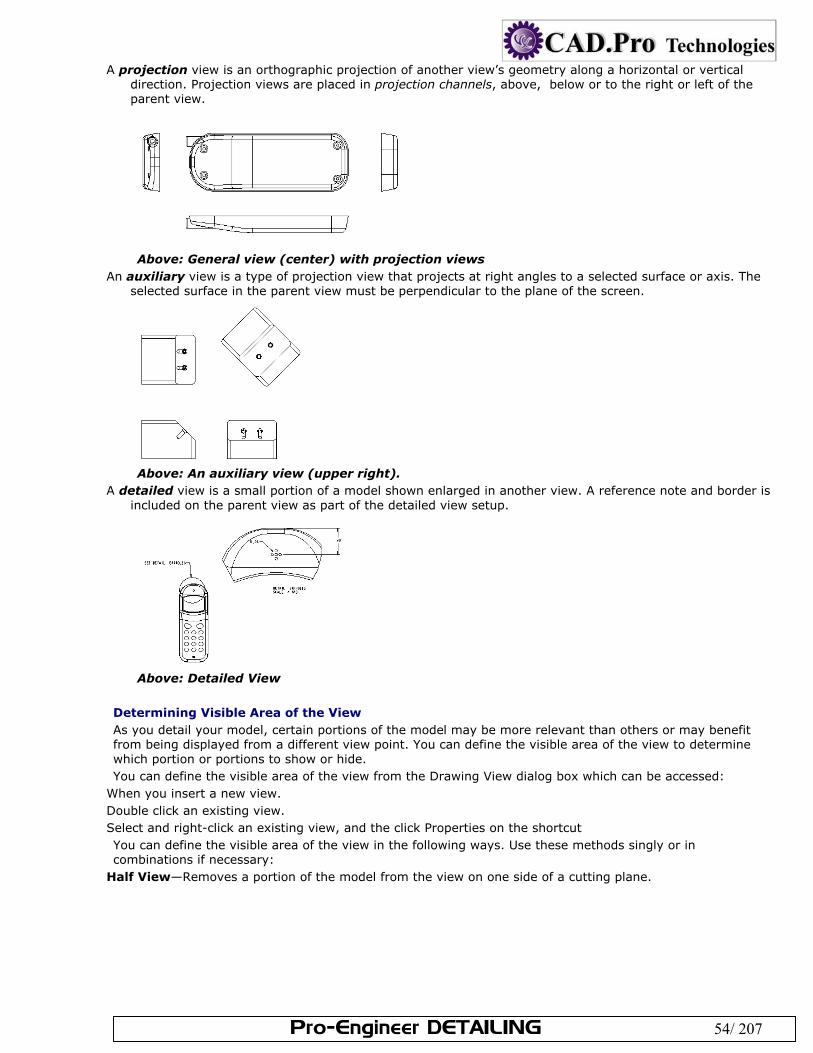
Pro-Engineer DETAILING 54/ 207
A projection view is an orthographic projection of another view’s geometry along a horizontal or vertical direction. Projection views are placed in projection channels, above, below or to the right or left of the parent view.
Above: General view (center) with projection views
An auxiliary view is a type of projection view that projects at right angles to a selected surface or axis. The selected surface in the parent view must be perpendicular to the plane of the screen.
Above: An auxiliary view (upper right).
A detailed view is a small portion of a model shown enlarged in another view. A reference note and border is included on the parent view as part of the detailed view setup.
Above: Detailed View
Determining Visible Area of the View As you detail your model, certain portions of the model may be more relevant than others or may benefit from being displayed from a different view point. You can define the visible area of the view to determine which portion or portions to show or hide. You can define the visible area of the view from the Drawing View dialog box which can be accessed:
When you insert a new view. Double click an existing view. Select and right-click an existing view, and the click Properties on the shortcut You can define the visible area of the view in the following ways. Use these methods singly or in combinations if necessary:
Half View—Removes a portion of the model from the view on one side of a cutting plane.
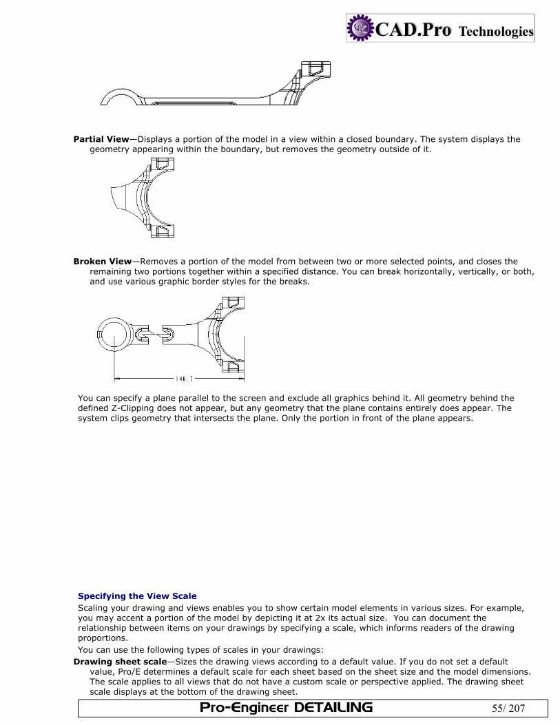
Pro-Engineer DETAILING 55/ 207
Partial View—Displays a portion of the model in a view within a closed boundary. The system displays the
geometry appearing within the boundary, but removes the geometry outside of it.
Broken View—Removes a portion of the model from between two or more selected points, and closes the remaining two portions together within a specified distance. You can break horizontally, vertically, or both, and use various graphic border styles for the breaks.
You can specify a plane parallel to the screen and exclude all graphics behind it. All geometry behind the defined Z-Clipping does not appear, but any geometry that the plane contains entirely does appear. The system clips geometry that intersects the plane. Only the portion in front of the plane appears.
Specifying the View Scale Scaling your drawing and views enables you to show certain model elements in various sizes. For example, you may accent a portion of the model by depicting it at 2x its actual size. You can document the relationship between items on your drawings by specifying a scale, which informs readers of the drawing proportions. You can use the following types of scales in your drawings:
Drawing sheet scale—Sizes the drawing views according to a default value. If you do not set a default value, Pro/E determines a default scale for each sheet based on the sheet size and the model dimensions. The scale applies to all views that do not have a custom scale or perspective applied. The drawing sheet scale displays at the bottom of the drawing sheet.
Pro-Engineer DETAILING 56/ 207
Custom scale—Sizes the view using a custom value typed in the View Dialog box. When you modify the drawing sheet scale, custom views do not change, since the scale factor is independent. The custom scale appears below each view, shown in a note "Scale <value>."
Perspective—Sizes the drawing using a combination of eye-point distance from model space and paper units, such as mm. This scale option is only available for general views.
A newly created view takes on the value of the drawing sheet scale, unless you specify a different scale value. You can change the scale of any existing view. When you change the size of the drawing, the drawing sheet scale changes to keep the views in proportion to the size of the sheet. However, detailed and scaled views retain their original scale regardless of changes to the drawing size. You can change drawing scales on each sheet independently. When you modify a drawing view scale, all related parent/child views (projected views, broken views, etc.) update accordingly. You can use relational expressions to drive a custom or perspective view scale; however, you cannot use them to drive views using the drawing sheet scale. When you type a relational expression for the view scale, the system calculates the expression and retains the information. This functionality enables you to relate the view scale using dimensions within the model. The system stores the relation with the model and updates the view scale each time the dimension in the model changes, along with all items related to it. Note:
you can control the initial setting of the default scale by setting the default_draw_scale configuration file option; otherwise, the size is automatically calculated based on the size of the model. You can override your settings by modifying the scale.
You can express drawing scales in a decimal or fractional format by setting the view_scale_format drawing setup file option (decimal format is the default).
To establish the pattern of fractional scales, use the view_scale_denominator drawing setup file option. If you change the drawing scale, symbols with a fixed size will not change. To change the symbol size you
should redefine the symbol attributes. To show or erase the view scale note, use the Show/Erase dialog box (click View > Show and Erase). To Specify the View Scale You can specify the scale for individual views when you add the view to the drawing, or you can modify the scale at any time. You can set the individual view scales in the following ways: Using the Drawing Sheet Scale By default, new views are set to display according to the drawing sheet scale. If you want to display the view at this scale simply place the view. The drawing sheet scale displays at the bottom of the drawing sheet, or you can view the value in the Scale category on the Drawing View dialog box. You can modify this value by:
Setting the default_draw_scale configuration file option. Double-clicking on the drawing sheet scale at the lower-left corner of the screen and then typing the real
value or relational expression. Selecting the drawing sheet scale at the lower-left corner of the screen and then right-clicking and clicking
Edit Value. Selecting the drawing sheet scale at the lower-left corner of the screen and then clicking Edit > Value. Using a Custom Scale You can define a custom drawing view proportion for individual views. With the Drawing View dialog box open, click the Scale category. The Scale and perspective options
display in the dialog box. Click Custom Scale. The scale box is enabled. Type a real value or relational expression in the box. Click Apply to see the size of the view with the new
scale. If scale is not acceptable, repeat the steps above by entering a different scale value. If the scale is appropriate and no changes needs to be made, select the next appropriate category to define or click Close.
Using Perspective With the Drawing View dialog box open, click the Scale category. The Scale and perspective options
display in the dialog box. Click Perspective. The distance and diameter boxes are enabled. The unit of measurement displays next to
each box. Type the desired value for the Eye-point distance, which measures the distance in model space. Type the desired value for the View diameter, which scales the view using paper units.
Pro-Engineer DETAILING 57/ 207
Click Apply to see the size of the view with the new scale. If scale is not acceptable, repeat the steps above by entering a different scale value. If the scale is appropriate and no changes needs to be made, select the next appropriate category to define or click Close.
Note: When using a relational expression, type only the right-hand side of the expression. The system calculates the
left-hand side as the view scale. To show or erase the view scale note, use the Show/Erase dialog box (click View > Show and Erase). Displaying Cross Sections in Drawings A cross section is an imaginary cutting plane applied through a part, with a cross hatch pattern associated with it. How the cross section is shown in a particular view is a function of that view's view type- full, half, local, etc. Before placing a cross section defined as planar in the view, you must orient the view so that the plane of the section is parallel to the plane of the screen. If the cross section is revolved, the plane of the section must be perpendicular to the screen. You can create cross-sections in part and assembly mode, which can be used to display portions of the component within drawings. These three-dimensional cross-sections are similar to assembly cuts, but are only used for display purposes. Note: If you want to redefine the side and direction of offset cross sections, you must do it in either Part or Assembly mode. You cannot redefine them in Drawing mode. To Display a 2D Cross Section View With the Drawing View dialog box open, use the View Type category to define the view orientation, so the
view you want to cross-section is oriented properly to the screen. Click the Sections category. The Section options display in the dialog box. Click 2D cross-section. The 2D cross-section properties table is enabled. If a 2D cross-section does not
exist in the drawing, you will need to create a new one. Otherwise you will either select an existing cross-section or create a new one.
Create 2D cross-section—If a 2D cross-section does not exist in the drawing or you need display another cross-section, you can create one:.
Select Create New from the Name list, located on 2D cross-section table. The XSEC CREATE menu appears in the menu manager. Define the cross-section as either Planar or Offset and select the appropriate attributes. Click Done. You are prompted to name the cross-section. Type the desired name and press ENTER. You are prompted to define the cross-section reference. Select and existing reference or create a new one. Only cross-sections parallel to the screen will be created.
Display existing 2D cross-section—If a 2D cross-section already exists in the model you can select it from the Name list, located on 2D cross-section table. The existing cross-sections are listed in alphabetical order. Valid cross-section are indicated by ; while indicates the cross-section is not parallel to the screen and can not be placed.
Once a valid cross section name is selected, define how to display the sectioned area. Select the visibility style from the Sectioned Area list:
Full— Half— Local— Full (Unfolded)— Full (Aligned)—
Note: You can display Full and Local cross-section visibility by defining two cross-sections; one with Full visibility and the other one with Local visibility. At any moment, there can at most be one section with Full visibility.
If you are displaying a Half, Local, or Full (Aligned) cross-section, you must define placement references. Click the yellow reference collector in the table and then select the appropriate reference on the drawing:
Half—Select a datum plane reference. The reference name is listed in the table if the reference is perpendicular to the view..
Local—Select a point reference. Make sure the point reference is outside any other section breakout splines. The geometry name is listed in the table and displays on the drawing.
Full (Aligned)—Select an axis reference. All cutting planes of the offset section should contain the reference axis. The axis name is listed in the table and displays on the drawing.
If you are displaying a Half cross-section, define the side of the reference plane that should be sectioned by clicking the drawing on the side of the reference plane.
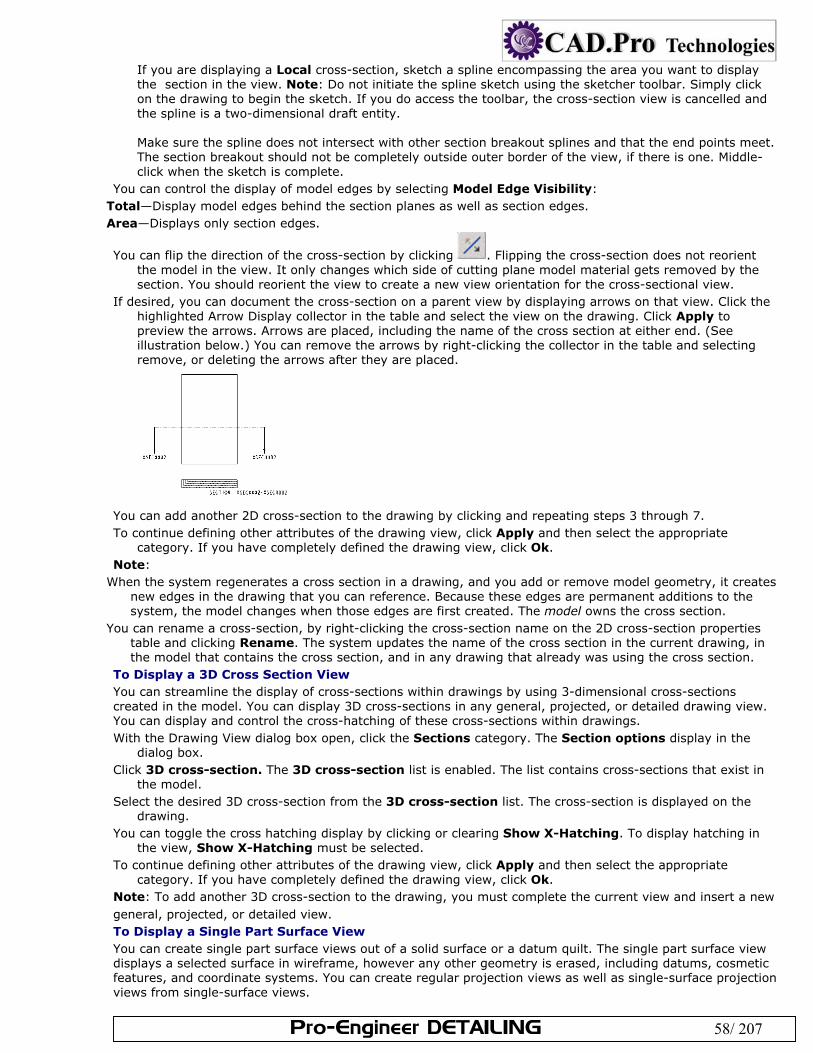
Pro-Engineer DETAILING 58/ 207
If you are displaying a Local cross-section, sketch a spline encompassing the area you want to display the section in the view. Note: Do not initiate the spline sketch using the sketcher toolbar. Simply click on the drawing to begin the sketch. If you do access the toolbar, the cross-section view is cancelled and the spline is a two-dimensional draft entity. Make sure the spline does not intersect with other section breakout splines and that the end points meet. The section breakout should not be completely outside outer border of the view, if there is one. Middle-click when the sketch is complete.
You can control the display of model edges by selecting Model Edge Visibility: Total—Display model edges behind the section planes as well as section edges. Area—Displays only section edges.
You can flip the direction of the cross-section by clicking . Flipping the cross-section does not reorient the model in the view. It only changes which side of cutting plane model material gets removed by the section. You should reorient the view to create a new view orientation for the cross-sectional view.
If desired, you can document the cross-section on a parent view by displaying arrows on that view. Click the highlighted Arrow Display collector in the table and select the view on the drawing. Click Apply to preview the arrows. Arrows are placed, including the name of the cross section at either end. (See illustration below.) You can remove the arrows by right-clicking the collector in the table and selecting remove, or deleting the arrows after they are placed.
You can add another 2D cross-section to the drawing by clicking and repeating steps 3 through 7. To continue defining other attributes of the drawing view, click Apply and then select the appropriate
category. If you have completely defined the drawing view, click Ok. Note:
When the system regenerates a cross section in a drawing, and you add or remove model geometry, it creates new edges in the drawing that you can reference. Because these edges are permanent additions to the system, the model changes when those edges are first created. The model owns the cross section.
You can rename a cross-section, by right-clicking the cross-section name on the 2D cross-section properties table and clicking Rename. The system updates the name of the cross section in the current drawing, in the model that contains the cross section, and in any drawing that already was using the cross section.
To Display a 3D Cross Section View You can streamline the display of cross-sections within drawings by using 3-dimensional cross-sections created in the model. You can display 3D cross-sections in any general, projected, or detailed drawing view. You can display and control the cross-hatching of these cross-sections within drawings. With the Drawing View dialog box open, click the Sections category. The Section options display in the
dialog box. Click 3D cross-section. The 3D cross-section list is enabled. The list contains cross-sections that exist in
the model. Select the desired 3D cross-section from the 3D cross-section list. The cross-section is displayed on the
drawing. You can toggle the cross hatching display by clicking or clearing Show X-Hatching. To display hatching in
the view, Show X-Hatching must be selected. To continue defining other attributes of the drawing view, click Apply and then select the appropriate
category. If you have completely defined the drawing view, click Ok. Note: To add another 3D cross-section to the drawing, you must complete the current view and insert a new general, projected, or detailed view. To Display a Single Part Surface View You can create single part surface views out of a solid surface or a datum quilt. The single part surface view displays a selected surface in wireframe, however any other geometry is erased, including datums, cosmetic features, and coordinate systems. You can create regular projection views as well as single-surface projection views from single-surface views.
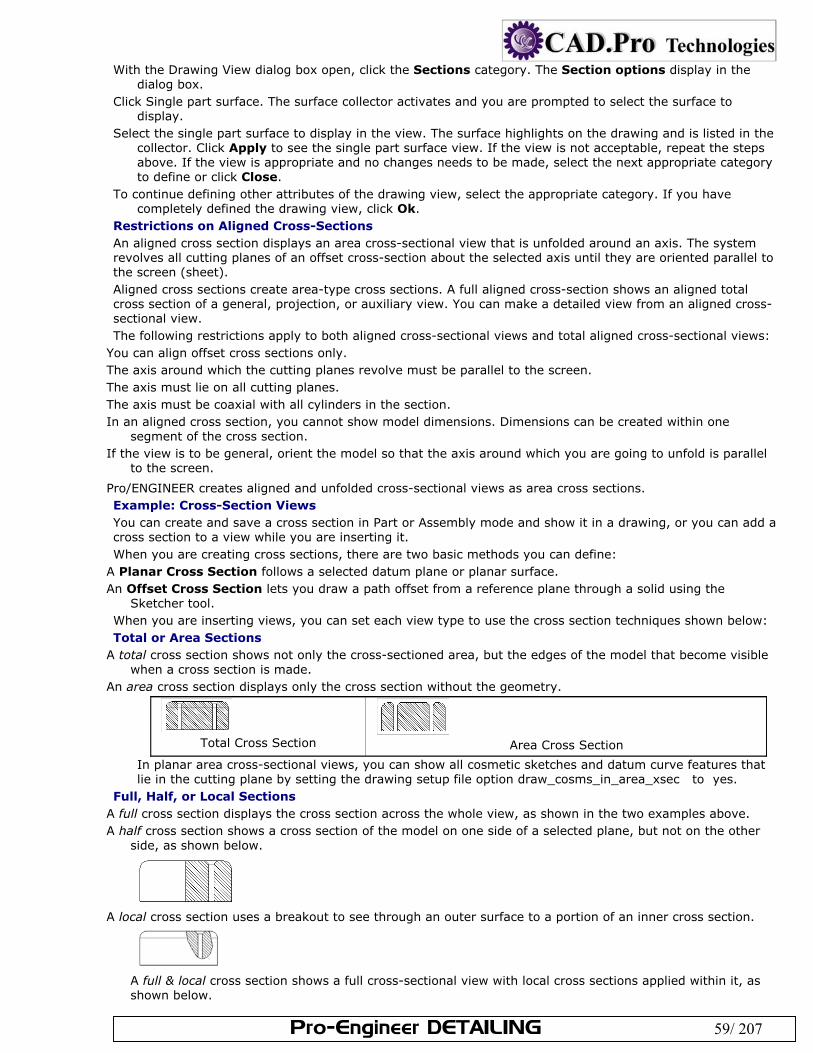
Pro-Engineer DETAILING 59/ 207
With the Drawing View dialog box open, click the Sections category. The Section options display in the dialog box.
Click Single part surface. The surface collector activates and you are prompted to select the surface to display.
Select the single part surface to display in the view. The surface highlights on the drawing and is listed in the collector. Click Apply to see the single part surface view. If the view is not acceptable, repeat the steps above. If the view is appropriate and no changes needs to be made, select the next appropriate category to define or click Close.
To continue defining other attributes of the drawing view, select the appropriate category. If you have completely defined the drawing view, click Ok.
Restrictions on Aligned Cross-Sections An aligned cross section displays an area cross-sectional view that is unfolded around an axis. The system revolves all cutting planes of an offset cross-section about the selected axis until they are oriented parallel to the screen (sheet). Aligned cross sections create area-type cross sections. A full aligned cross-section shows an aligned total cross section of a general, projection, or auxiliary view. You can make a detailed view from an aligned cross-sectional view. The following restrictions apply to both aligned cross-sectional views and total aligned cross-sectional views:
You can align offset cross sections only. The axis around which the cutting planes revolve must be parallel to the screen. The axis must lie on all cutting planes. The axis must be coaxial with all cylinders in the section. In an aligned cross section, you cannot show model dimensions. Dimensions can be created within one
segment of the cross section. If the view is to be general, orient the model so that the axis around which you are going to unfold is parallel
to the screen.
Pro/ENGINEER creates aligned and unfolded cross-sectional views as area cross sections. Example: Cross-Section Views You can create and save a cross section in Part or Assembly mode and show it in a drawing, or you can add a cross section to a view while you are inserting it. When you are creating cross sections, there are two basic methods you can define:
A Planar Cross Section follows a selected datum plane or planar surface. An Offset Cross Section lets you draw a path offset from a reference plane through a solid using the
Sketcher tool. When you are inserting views, you can set each view type to use the cross section techniques shown below: Total or Area Sections
A total cross section shows not only the cross-sectioned area, but the edges of the model that become visible when a cross section is made.
An area cross section displays only the cross section without the geometry.
Total Cross Section
Area Cross Section
In planar area cross-sectional views, you can show all cosmetic sketches and datum curve features that lie in the cutting plane by setting the drawing setup file option draw_cosms_in_area_xsec to yes.
Full, Half, or Local Sections A full cross section displays the cross section across the whole view, as shown in the two examples above. A half cross section shows a cross section of the model on one side of a selected plane, but not on the other
side, as shown below.
A local cross section uses a breakout to see through an outer surface to a portion of an inner cross section.
A full & local cross section shows a full cross-sectional view with local cross sections applied within it, as shown below.
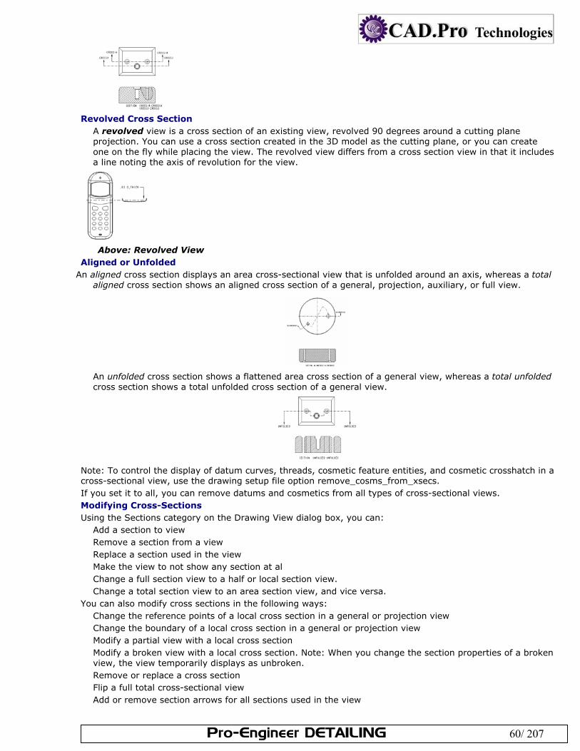
Pro-Engineer DETAILING 60/ 207
Revolved Cross Section
A revolved view is a cross section of an existing view, revolved 90 degrees around a cutting plane projection. You can use a cross section created in the 3D model as the cutting plane, or you can create one on the fly while placing the view. The revolved view differs from a cross section view in that it includes a line noting the axis of revolution for the view.
Above: Revolved View
Aligned or Unfolded An aligned cross section displays an area cross-sectional view that is unfolded around an axis, whereas a total
aligned cross section shows an aligned cross section of a general, projection, auxiliary, or full view.
An unfolded cross section shows a flattened area cross section of a general view, whereas a total unfolded cross section shows a total unfolded cross section of a general view.
Note: To control the display of datum curves, threads, cosmetic feature entities, and cosmetic crosshatch in a cross-sectional view, use the drawing setup file option remove_cosms_from_xsecs. If you set it to all, you can remove datums and cosmetics from all types of cross-sectional views. Modifying Cross-Sections Using the Sections category on the Drawing View dialog box, you can:
Add a section to view Remove a section from a view Replace a section used in the view Make the view to not show any section at al Change a full section view to a half or local section view. Change a total section view to an area section view, and vice versa.
You can also modify cross sections in the following ways: Change the reference points of a local cross section in a general or projection view Change the boundary of a local cross section in a general or projection view Modify a partial view with a local cross section Modify a broken view with a local cross section. Note: When you change the section properties of a broken view, the view temporarily displays as unbroken. Remove or replace a cross section Flip a full total cross-sectional view Add or remove section arrows for all sections used in the view
Pro-Engineer DETAILING 61/ 207
You can delete a cross section definition from a model without having to retrieve the model. You cannot delete a cross section when it is being used by a drawing in session. Deleting a cross section in the drawing also deletes it in other drawings. To delete a section not used in any drawing in the current Pro/Engineer session, select a section view and access the Drawing View dialog box by either double-clicking, right-clicking and selecting Properties, or by clicking Edit > Properties. Click on Sections category, in a section name list cell, select the name of the section you want to delete. Right-click and click Delete from Model. Note: You can Include surfaces in drawing cross-sections by setting the show_quilts_in_total_xsecs detail setup file option. Displaying Cross-Section Datum Planes Using the Show/Erase dialog box (View > Show and Erase on the menu bar), you can display set datum planes in area cross-sectional views. Set datums that you display this way behave identically to those in other views; you can perform all usual detail actions on them, including dimensioning. Moving Cross-Section Arrows or Text You can move cross-section arrows or cross-section text. When you select a cross-section arrow, you can move it independently of the other cross-section arrowhead. To move the arrows simultaneously, select the arrow line. To change the cross-section text, change the name of the cross section in either Part or Assembly mode. Do one of the following:
Select text to move independently of the arrows Select an arrowhead to move the arrow and text together, independently of the other cross-section arrowhead Select an arrow line to move the arrows simultaneously Click to place the arrow in the new location. To Modify Cross-Section Text On the menu bar, click Format > Text Style. Select any of the cross section names. In the Text Style dialog box, clear the Default check box for Height, and type a new value. Clear the Use Default check for Width Factor, and type a new value. Click Apply. The height and width of the selected item changes. To reset the text to the old style, click Reset Settings, and then click Apply. Note: To show or erase a cross-sectional view name, use the Show/Erase dialog box (View > Show and Erase). Controlling the Cutting Line Display You can control the display of the cutting line in a cross-sectional view by setting the following drawing setup file options.
Click File > Properties. The menu manager opens. Click Draw Setup. The Options dialog box opens. Set the following drawing setup file options:
cutting_line—Determines the standard (ANSI, ISO) for the cutting line display cutting_line_adapt—Sets the display of all line fonts used to display cross-sectional views adaptive so that they begin in the middle of a complete line segment and end in the middle of a complete line segment cutting_line_segment—Controls the length of the thickened portion of the cutting line
Showing Threads in Cross-Section Assembly Views To display threads in cross-sectional assembly drawings according to the ISO or ANSI standard, use the thread_standard drawing setup file option in conjunction with hlr_for_threads.
To display them in accordance with the ANSI standard, set the drawing setup file option thread_standard to std_ansi_imp_assy.
To display them in accordance with the ISO 6410 standard, set it to std_iso_imp_assy. Note: In the ISO-standard display, if the bolt diameter equals the hole thread diameter, and the bolt thread diameter equals the hole diameter, the bolt covers the hole’s crosshatch if one of these conditions exists:
The bolt and hole are coaxial. Both axes are in the cross section. The cross section itself is planar and parallel to the screen (normal to the viewing direction). In the case of an offset cross section, the portion of the cross section that intersects the bolt/hole pair must be planar and parallel to the screen. About Modifying Crosshatch Using the Edit > Properties command, you can modify the crosshatch of detailed views and individual members of assembly cross-sectional views.
Pro-Engineer DETAILING 62/ 207
Assembly cross sections—When modifying an assembly cross section, you can modify individual components of the assembly intersected by the cross section.
Detailed views—The crosshatch of a detailed view can follow that of its parent view, or you can make the detailed view independent of its parent. To modify the crosshatch of a detailed view, you must make the detailed view independent of its parent (the View Display category on the Drawing View dialog box).
Note: If you have overlapping crosshatch patterns in your drawing (any combination of crosshatched cosmetic features, cross-sectional views, or draft cross sections), move the mouse over the cross hatch area and then right-click and click Pick From List to select the crosshatch to modify. Using Smart Default Crosshatch When you create an assembly cross section, the system automatically applies a "smart" crosshatch pattern on the parts that provides a superior visual representation of the cross section. Smart crosshatch applies crosshatch spacing appropriate to the model size and assigns different angles to different parts in the assembly. Smart crosshatch uses a randomized slant angle between adjacent components, making it easier to distinguish different parts in assembly drawings and also reducing the amount of time required to clean up drawings with cross sections and crosshatch. The following rules apply:
Smart default crosshatch affects newly created cross-sectional views only. When you retrieve previously saved drawings, smart crosshatch is not in effect.
For assembly cross sections, smart default crosshatch applies to both spacing and angle. For part cross sections, smart default crosshatch applies to spacing only. By default, the angle is 45 degrees for parts.
To override smart default crosshatch for newly created cross sections, define cross section parameters default_xhatch_spacing and default_xhatch_angle. Cross sections of other surrounding parts that are not defined adjust accordingly.
Smart default crosshatch no longer applies after you modify the crosshatch until you create a new view. Modifications made in Drawing mode do not display in Part mode or Assembly mode. Modifications
automatically override smart default crosshatch in a drawing. Controlling the Spacing and Angle of Crosshatch Using Parameters By setting parameters, you can control the default spacing and angle of crosshatch in newly created planar and offset cross sections. To control the display, set the number parameters using default_xhatch_spacing and default_xhatch_angle. These parameters only affect new cross sections—they do not affect cross sections previously created in a part or assembly. Determining Crosshatching Patterns Crosshatching patterns may be based on the assigned material of the part. For example, if you create a cross-section that cuts through a defined material such as steel, the system looks for a crosshatching pattern that has the same name as the assigned material. If the system finds such a pattern, it automatically assigns it to the cross-section. If the cross-section does not have a defined material, the system assigns the default crosshatching style. Notes:
If either of the two parameters default_xhatch_angle or default_xhatch_spacing are defined for the part containing the cross-section, these parameter settings supersede other definitions of the crosshatching style. That is, the existence of an assigned material name is no longer relevant to the assignment of the crosshatching style.
To control the display of datum curves, threads, cosmetic feature entities, and cosmetic crosshatch in a full cross-sectional view, use the drawing setup file option remove_cosms_from_xsecs. If you set it to all, you can remove datums and cosmetics from all types of cross-sectional views.
You can assign a name to a crosshatch pattern and save it for later retrieval by using the configuration file option pro_crosshatch_dir to specify a default directory for crosshatch patterns. Its value is the full path name of the default directory. To Modify Crosshatch Patterns
Select the cross hatching to modify. Click Edit > Properties.. Using the MOD XHATCH menu on the Menu Manager, do one of the following:
Modify the spacing. Click Spacing; then choose Half, Double, or Value from the MODIFY MODE menu. Specify which lines to change by choosing Individual or Overall. The system automatically scales the crosshatch offset, as well as the spacing, according to the command you choose for spacing.
Modify the angle. Click Angle; then choose Individual or Overall from the MODIFY MODE menu. The system changes only the first line of the pattern. Click an angle (0, 30, 45, 60, 90, 120, 135, 150) or Value to specify a different angle.
Modify the offset. Click Offset; then type a value for the offset in drawing units. Modify the line style. Click Line Style; then use the Line Style dialog box to change the line style.
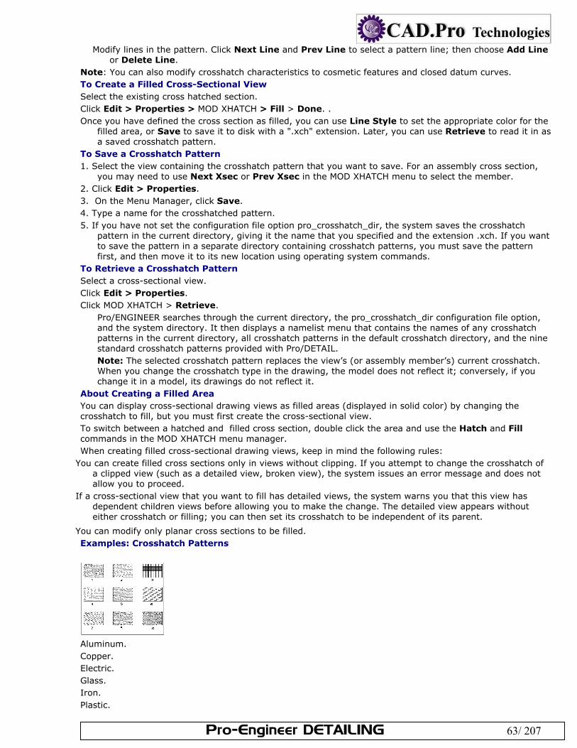
Pro-Engineer DETAILING 63/ 207
Modify lines in the pattern. Click Next Line and Prev Line to select a pattern line; then choose Add Line or Delete Line.
Note: You can also modify crosshatch characteristics to cosmetic features and closed datum curves. To Create a Filled Cross-Sectional View Select the existing cross hatched section. Click Edit > Properties > MOD XHATCH > Fill > Done. . Once you have defined the cross section as filled, you can use Line Style to set the appropriate color for the
filled area, or Save to save it to disk with a ".xch" extension. Later, you can use Retrieve to read it in as a saved crosshatch pattern.
To Save a Crosshatch Pattern 1. Select the view containing the crosshatch pattern that you want to save. For an assembly cross section,
you may need to use Next Xsec or Prev Xsec in the MOD XHATCH menu to select the member. 2. Click Edit > Properties. 3. On the Menu Manager, click Save. 4. Type a name for the crosshatched pattern. 5. If you have not set the configuration file option pro_crosshatch_dir, the system saves the crosshatch
pattern in the current directory, giving it the name that you specified and the extension .xch. If you want to save the pattern in a separate directory containing crosshatch patterns, you must save the pattern first, and then move it to its new location using operating system commands.
To Retrieve a Crosshatch Pattern Select a cross-sectional view. Click Edit > Properties. Click MOD XHATCH > Retrieve.
Pro/ENGINEER searches through the current directory, the pro_crosshatch_dir configuration file option, and the system directory. It then displays a namelist menu that contains the names of any crosshatch patterns in the current directory, all crosshatch patterns in the default crosshatch directory, and the nine standard crosshatch patterns provided with Pro/DETAIL. Note: The selected crosshatch pattern replaces the view’s (or assembly member’s) current crosshatch. When you change the crosshatch type in the drawing, the model does not reflect it; conversely, if you change it in a model, its drawings do not reflect it.
About Creating a Filled Area You can display cross-sectional drawing views as filled areas (displayed in solid color) by changing the crosshatch to fill, but you must first create the cross-sectional view. To switch between a hatched and filled cross section, double click the area and use the Hatch and Fill commands in the MOD XHATCH menu manager. When creating filled cross-sectional drawing views, keep in mind the following rules:
You can create filled cross sections only in views without clipping. If you attempt to change the crosshatch of a clipped view (such as a detailed view, broken view), the system issues an error message and does not allow you to proceed.
If a cross-sectional view that you want to fill has detailed views, the system warns you that this view has dependent children views before allowing you to make the change. The detailed view appears without either crosshatch or filling; you can then set its crosshatch to be independent of its parent.
You can modify only planar cross sections to be filled. Examples: Crosshatch Patterns
Aluminum. Copper. Electric. Glass. Iron. Plastic.
Pro-Engineer DETAILING 64/ 207
Steel. Titanium.
Zinc. Showing Models in Various View States You can add an exploded view of an assembly without having to explode it in Assembly mode. The Exploded state is an assembly view property that overrides any saved exploded views in the 3D assembly. To be shown as exploded for an assembly view, you need to select the view and access the Drawing View dialog box by either double-clicking, right-clicking and selecting Properties, or by clicking Edit > Properties. Change explode property in View States category. All saved explode states that are saved in 3D mode are available in the Assembly Explode State list. You can modify the explosion distances between components, however, this alters the drawing cosmetically and does not modify the actual exploded dimensions of the model. To Create an Exploded View You can create and save multiple assembly explode states. With the Drawing View dialog box open, click the View States category. The view state options display in
the dialog box. To separate the components of the model, click Explode components in view. The Assembly explode state list
is enabled. You can either select a predefined exploded view from the Assembly explode state or create a new state. If
you select an existing explode state, click Apply to see the explode state view. If the view is not acceptable, repeat the steps above. If the view is appropriate and no changes needs to be made, select the next appropriate category to define or click Close. If you need to create a new explode state, click Customize explode estate. The Explode Position dialog box opens and you are prompted to select a component to move. Select the component to reposition on the drawing. The component highlights and the component name
is listed under Select Component on the Explode Position dialog box. Under Motion Type, define how you want to move the component:
Translate— Copy Pos— Default Expld— Reset—
Under Motion Reference, select a reference type from the list and then select a reference on the drawing. The reference name is displayed on the dialog box.
Under Motion Increments, define how to translate the component movement. Type or select a translation type from the Translation list.
Drag the component to its desired location on the drawing. The sheet coordinates for the component display under Position. Repeat steps a. through e. for each component you need to reposition. When you are have exploded the desired components, click Ok on the Explode Position dialog box. Then click Done/Return on the MOD EXPLODE menu.
To continue defining other attributes of the drawing view, click Apply and then select the appropriate category. If you have completely defined the drawing view, click Ok.
To Display Representations in Drawings You can display representations of assembly models in the drawing:
With the Drawing View dialog box open, click the View States category. The view state options display in the dialog box. Under Simplified representation, select the name of the simplified representation to use. Click Apply. The simplified representation is displayed on the drawing.
Note: If the Drawing View dialog box is open for a view whose model was simplified using the, now no longer supported, Represent functionality, Restore to non-simplified state appears in View States category. If you click Restore to non-simplified state and then click Apply, the view's model will be restored to a nonsimplified state, and normal view state properties like explode and assembly simplified representations can be accessed. To Display Process Steps If the manufacturing process was identified in the assembly, you can display manufacturing process steps in drawing views: With the Drawing View dialog box open, click the View States category. The view state options display in
the dialog box.
Pro-Engineer DETAILING 65/ 207
Under Process Step, select the name of the assembly step from the Process assembly step list. The view of the assembly step is displayed on the drawing.
Note: If the Drawing View dialog box is open for a view whose model was simplified using the, now no longer supported, Represent functionality, Restore to non-simplified state appears in View States category. If you click Restore to non-simplified state and then click Apply, the view's model will be restored to a nonsimplified state, and normal view state properties like explode and assembly simplified representations can be accessed. Using Simplified Representations Using commands in the File > Properties > DWG MODELS menu, you can create assembly views using simplified representations. Pro/ENGINEER limits simplified representations to assembly views, and you must specify them before adding a view. You can add multiple views of an assembly, each of a different representation, to a drawing. When working with simplified representations in Drawing mode, you can use geometry representations—a type of advanced simplified representation. Geometry representations require less time to retrieve than the actual part because the system does not retrieve any of the parametric information, only the geometry. You can use them to remove hidden lines, obtain measure information, and accurately calculate mass properties. When working with geometry representations, keep in mind the following:
By default, you cannot create drawing references to geometry representations (this includes dimensions, notes, and leaders), but if you set the configuration file option allow_reps_to_geom_reps_in_drws to yes, you can create references. However, these references may become invalid if the referenced geometry changes. This option is for advanced users who are aware that some references to geometry representations may not be updated in drawings.
Graphics representations are not available. If you include graphics representations in a drawing view of a simplified representation, the system changes those representations to geometry representations.
Changing the Representation of an Assembly Model __top_invis_menu@drawing@detail@file#properties@dwg#models@set/add#rep After adding an assembly model to a drawing, you can change its representation by choosing File > Properties > DWG MODELS > Set/Add Rep. However, the current model must be an assembly model. Selecting a view sets the current representation to the representation shown in that view—you can select only views of the current drawing model. You can use Sel By Menu to access a list of all representations that exist for the current assembly. The system makes the specified representation the active representation and applies it to subsequent views. If simplified representations have been made for the assembly model, it automatically retrieves the Master Representation. When creating simplified representations in Drawing mode and making changes to them, you should keep in mind the following:
In Assembly mode, simplified representations can contain substitute parts. In Drawing mode, you can only apply dimensions to these substitute parts by creating them. When creating the dimension you should reference the geometry of the simplified representation.
When you make changes to a simplified representation in Assembly mode, you may lose information in the drawing. For example, when you change the status of a component by substituting a previously included component, all references to the substituted component are lost.
When referencing an assembly or its components in a simplified representation, the system can find and use only those components that actually exist in the simplified representation. Specifically, when you orient a view, you cannot use datums belonging to or placed according to components that are not in the current simplified representation.
You can make projected, auxiliary, revolved, and detailed views from a general view of the same simplified representation.
Removing Simplified Representations from Session Once you add a representation of an assembly model to a drawing, it remains in session until you explicitly remove it. If a drawing view refers to the particular simplified representation you choose to delete, the system does not allow you to delete it while the drawing is in session, and it attempts to retrieve the Master Representation. If you do remove it from session and delete it, this causes an error when you retrieve the drawing. The system prompts you to select an existing representation from the RMV REP menu, and assigns this representation to all views that previously referred to the deleted representation. If the Master Representation of the assembly no longer exists, you cannot retrieve the drawing. Click File > Properties. The Menu Manager opens. Click Drawing Models > Remove Rep. (The current model must be an assembly model having more than
one representation in session.) The RMV REP menu appears, listing only the representations that the drawing references.
Pro-Engineer DETAILING 66/ 207
Select a representation that a drawing is not using. You can choose one representation at a time. The system prompts you for verification before deleting each one.
To Replace a View of a Simplified Representation You can replace a view of a simplified representation (including the Master Representation) with another simplified representation. Select the view. From the right mouse button shortcut menu, click Properties. The Drawing View dialog box
opens. Click the View States category. Select a simplified representation from the list of available representations to use as a replacement. Click
Apply. The view is replaced. To continue defining other attributes of the drawing view, select the appropriate category. If you have completely defined the drawing view, click Ok.
To Retrieve an Assembly Model Simplified Representation Click File > Properties. The menu manager opens. Click DWG MODELS > Add Model. Select an assembly name. The SELECT REP menu (in Assembly mode) appears when you retrieve the initial
assembly and for all assembly models that you add subsequently. It lists the Master Representation and all simplified representations that exist for the current assembly. If none have been created for the assembly model, it does not appear, and the system automatically retrieves the Master Representation.
Select a representation. The system applies that representation to subsequent views. You can accept the Master Representation as the default, or select a different representation to retrieve.
Modifying View and Edge Display You can define display settings that apply to all drawing views or you customize the display of individual views. For example, you may show one view of a model with hidden lines, and then depict a detailed view of the model with wireframe. The various view display options can be applied to individual views, edges, or assembly members. If multiple items are selected, any display changes you make are applied to all the selected views. Note:
Once you have set the display mode for a specific view, it remains set regardless of the setting in the Environment dialog box, unless you choose Default
The hlr_for_quilts configuration file option controls how the system displays quilts in the hidden line removal process.
The hlr_for_pipe_solid_cl drawing setup file option controls how hidden line affects pipe centerlines. This option only controls pipes created in Pro/PIPING, not on pipe features in a part.
To Modify View Display If multiple views are selected, only the View Display category is available on the Drawing View dialog box. All the display options are available. Any changes you make are applied to all the selected views. With a view or multiple views selected and the Drawing View dialog box open, click the View Display
category. The View display options display in the dialog box. If a detailed view is selected, to have its display mirror the display of the parent view click Use parent view
style. When cleared, the detailed view display is independent of its parent view and you can modify the display as necessary.
Define how to show the model geometry by selecting a Display style: Default—Uses the setting from the Tools > Environment > Display Style or the view display style icon in the
window.
Wireframe—Shows all edges in wireframe style
Hidden—Shows all edges in hidden line style
No Hidden—Removes all hidden edge from view display Note: If you have set the view display mode to Wireframe, the system does not erase or redisplay its edges until you change the view display to Hidden or No Hidden.
Define how to show the tangent edges on the model by selecting a tangent edge display style: Default—Uses the setting from the Tools > Environment > Tangent Edges.
None—Turns off the display of tangent edges
Solid—Displays tangent edges
Dimmed—Displays tangent edges in dimmed color
Centerline—Displays tangent edges in centerline font
Pro-Engineer DETAILING 67/ 207
Phantom—Displays tangent edges in phantom font Determine whether hidden lines will be removed for quilts by selecting the appropriate option:
Yes—Hidden lines are removed from the view. No—Hidden lines are shown in the view. Define how to show the skeleton model:
Hide—Skeleton model is not displayed. Show—Skeleton model is shown in the view. Define how to display cable geometry in the drawing:
Default—Uses the display setting from Tools > Environment. Centerline—Display cable geometry in centerline font Thick—Display cable geometry in thick font Define where the drawing should look for color designations:
The drawing—Drawing colors are determined by drawing settings. The model—Drawing colors are determined by model settings.
Note:Model colors and assigned drawing colors in a drawing for a process assembly are always superceded by any existing process assembly colors.
Define whether weldment cross-sections should be shown in the drawing: Hide—Weldment cross-sections are not displayed in the view. Show—Weldment cross-sections are shown in the view. To continue defining other attributes of the drawing view, click Apply and then select the appropriate
category. If you have completely defined the drawing view, click Ok. Note: Once you have set the display mode for a specific view, it remains set regardless of the setting in the Environment dialog box, unless you choose Default To Modify Individual Edge Display Click View > Drawing Display > Edge Display. The Select dialog box opens and EDGE DISP menu
appears in the menu manager. Select the edge or edges to modify. The selected edges highlight. Define the edge display using the options on the EDGE DISP menu. Click Done when you have modified the
desired edges. Note: Keep the following in mind when modifying individual edges on a drawing:You cannot use the it to erase the following items:
Boundaries of all cross sections Outside edges intersecting clipped splines in partial or detailed views Cosmetic threads in drawing views (choose Show and Erase from the View menu; then click the Cosmetic
Feature button in the Type box of the Show/Erase dialog box) Silhouette edges, except for the following:
Silhouette edges of cylinders and cones Silhouette edges of torii that are arcs, that is, the axes of the torii are either parallel or perpendicular to
the screen Silhouettes of general surfaces of revolution whose axes are parallel to the screen Note: If you erase one silhouette edge, the system erases all silhouette edges that belong to the same surface.
To Modify the Line Style of Assembly Members Click View > Drawing Display > Component Display. The menu manager opens. Select the assembly components. Click OK in the confirmation box. The Memb Style menu opens. Change the style by selecting a command:
Standard—Displays the selected member view in solid line style. PhantomOpque—Displays the selected member view in phantom line style. PhantomTrnsp—Displays the selected member view in phantom line style, but the hidden line removal process does not affect it. User Color—Creates a user-defined color and assigns it to an assembly member.
Click Done. Tip: Using Model Colors in Drawings You can toggle color display of selected views in Drawing mode between the assigned drawing colors and the colors used in the original model. Important Points about Using Model Colors in Drawings
Pro-Engineer DETAILING 68/ 207
Views that are displayed in the original model colors are plotted (printed) as such. Changing the color of individual geometry does not change the colors in views that display the original model
colors. If you change model colors in the associated model, the new model colors are updated automatically in the
drawing, if you set the drawing views to use model colors. Hidden lines in drawing views always take on the original standard hidden line color in the model. Any assigned process assembly colors always supercede the setting for using model colors or assigned
drawing colors in the drawing. Tip: Simplifying Edge Selection When drawing views display as No Hidden, you can disallow selection of edges in drawings. The select_hidden_edges_in_dwg configuration file option disallows the selection of No Hidden edges by rejecting edges behind the first surface in the viewing plane. The following requirements apply:
Selection is disallowed for drawing views in No Hidden display mode only. View regeneration is required on cross-sectional views.
You can disallow the selection of edges in general and cross-section views. Defining the View Origin By default, the origin of a drawing view is in the center of its outline. You can reset the origin of a drawing view by parametrically referencing model geometry or defining a location on the drawing sheet. Designating an origin identifies the view location on the drawing and prevents it from shifting whenever the model geometry changes. You can reset the origin of general, auxiliary, and broken views any time after you create them, but it does not change the current position of the view. The effect of the new origin is noticeable only when the system updates the views to reflect changes in model geometry. However, if you reset the origin of a perspective view, it alters the current position of the view because the view origin is part of the orientation. Note: You cannot change the view origins of total unfolded cross-sectional views. To select the point for the origin, you can choose a model edge, datum curve, datum point, coordinate system, or cosmetic feature entity. However, when selecting a point, keep the following in mind:
For a general view, the selected point becomes fixed. For a projection and auxiliary view, the system passes the selected point onto a ray passing through the origin
of the parent view in the direction of projection. This projected point becomes the origin of the view. To select a coordinate system as the origin of a newly created view or of a modified view, specify its name as
the value for the configuration file option "drawing_view_origin_csys." If you do not want the system to use a coordinate system that you set previously, specify the value as "no."
To Define the View Origin The placing and positioning of views on drawings uses the view origin as a reference, with the exception of custom view alignments. You can specify the view origin using a location on either the model or the drawing sheet. With a view selected and the Drawing View dialog box open, click the Origin category. The View origin
options display in the dialog box. Define the location of the view origin in one of the following ways:
View origin—Define the origin using the model. To customize the view origin, click On item and then select the model reference you want to use as the view origin. The item is listed in the collector. The view will reference this item when positioned on the drawing. To use the model center, which is the default setting, make sure Model center is selected.
View location on sheet—Define the origin using drawing sheet measurements. Note: If the geometry referenced in a view is suppressed or deleted, the system warns you that model geometry is missing. For views oriented with the suppressed or deleted reference, the view returns to its default position. To Align a View Depending on the type of view, you can position the drawing view on the sheet by aligning the view with another view. For example, you may align a detail view with its parent to ensure that the detail view follows the parent view, if moved. The view will remain aligned and move like a projection view until it is unaligned. If you need to unalign, simply clear Align this view with other view. You can realign a view by changing the alignment references, which are described below.
With a view selected and the Drawing View dialog box open, click the Alignment category. The View alignment options display in the dialog box.
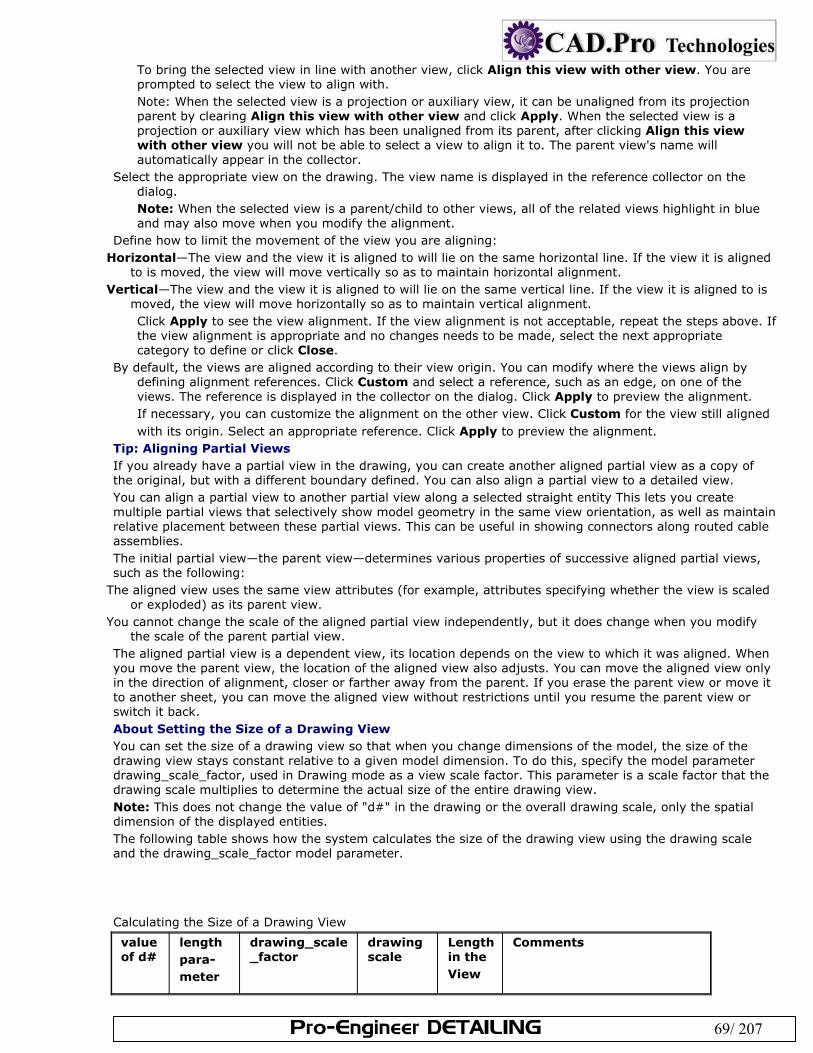
Pro-Engineer DETAILING 69/ 207
To bring the selected view in line with another view, click Align this view with other view. You are prompted to select the view to align with. Note: When the selected view is a projection or auxiliary view, it can be unaligned from its projection parent by clearing Align this view with other view and click Apply. When the selected view is a projection or auxiliary view which has been unaligned from its parent, after clicking Align this view with other view you will not be able to select a view to align it to. The parent view's name will automatically appear in the collector.
Select the appropriate view on the drawing. The view name is displayed in the reference collector on the dialog. Note: When the selected view is a parent/child to other views, all of the related views highlight in blue and may also move when you modify the alignment.
Define how to limit the movement of the view you are aligning: Horizontal—The view and the view it is aligned to will lie on the same horizontal line. If the view it is aligned
to is moved, the view will move vertically so as to maintain horizontal alignment. Vertical—The view and the view it is aligned to will lie on the same vertical line. If the view it is aligned to is
moved, the view will move horizontally so as to maintain vertical alignment. Click Apply to see the view alignment. If the view alignment is not acceptable, repeat the steps above. If the view alignment is appropriate and no changes needs to be made, select the next appropriate category to define or click Close.
By default, the views are aligned according to their view origin. You can modify where the views align by defining alignment references. Click Custom and select a reference, such as an edge, on one of the views. The reference is displayed in the collector on the dialog. Click Apply to preview the alignment. If necessary, you can customize the alignment on the other view. Click Custom for the view still aligned with its origin. Select an appropriate reference. Click Apply to preview the alignment.
Tip: Aligning Partial Views If you already have a partial view in the drawing, you can create another aligned partial view as a copy of the original, but with a different boundary defined. You can also align a partial view to a detailed view. You can align a partial view to another partial view along a selected straight entity This lets you create multiple partial views that selectively show model geometry in the same view orientation, as well as maintain relative placement between these partial views. This can be useful in showing connectors along routed cable assemblies. The initial partial view—the parent view—determines various properties of successive aligned partial views, such as the following:
The aligned view uses the same view attributes (for example, attributes specifying whether the view is scaled or exploded) as its parent view.
You cannot change the scale of the aligned partial view independently, but it does change when you modify the scale of the parent partial view.
The aligned partial view is a dependent view, its location depends on the view to which it was aligned. When you move the parent view, the location of the aligned view also adjusts. You can move the aligned view only in the direction of alignment, closer or farther away from the parent. If you erase the parent view or move it to another sheet, you can move the aligned view without restrictions until you resume the parent view or switch it back. About Setting the Size of a Drawing View You can set the size of a drawing view so that when you change dimensions of the model, the size of the drawing view stays constant relative to a given model dimension. To do this, specify the model parameter drawing_scale_factor, used in Drawing mode as a view scale factor. This parameter is a scale factor that the drawing scale multiplies to determine the actual size of the entire drawing view. Note: This does not change the value of "d#" in the drawing or the overall drawing scale, only the spatial dimension of the displayed entities. The following table shows how the system calculates the size of the drawing view using the drawing scale and the drawing_scale_factor model parameter. Calculating the Size of a Drawing View
value of d#
length para- meter
drawing_scale _factor
drawing scale
Length in the View
Comments
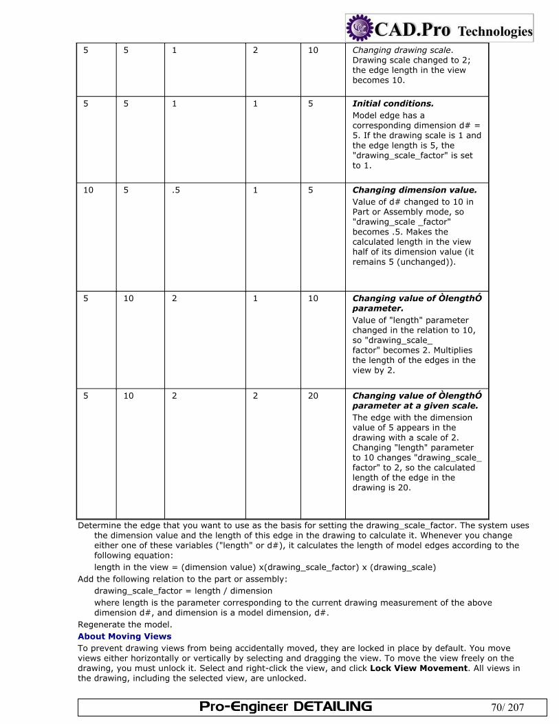
Pro-Engineer DETAILING 70/ 207
5 5 1 2 10 Changing drawing scale. Drawing scale changed to 2; the edge length in the view becomes 10.
5 5 1 1 5 Initial conditions. Model edge has a corresponding dimension d# = 5. If the drawing scale is 1 and the edge length is 5, the "drawing_scale_factor" is set to 1.
10 5 .5 1 5 Changing dimension value. Value of d# changed to 10 in Part or Assembly mode, so "drawing_scale _factor" becomes .5. Makes the calculated length in the view half of its dimension value (it remains 5 (unchanged)).
5 10 2 1 10 Changing value of ÒlengthÓ parameter. Value of "length" parameter changed in the relation to 10, so "drawing_scale_ factor" becomes 2. Multiplies the length of the edges in the view by 2.
5 10 2 2 20 Changing value of ÒlengthÓ parameter at a given scale. The edge with the dimension value of 5 appears in the drawing with a scale of 2. Changing "length" parameter to 10 changes "drawing_scale_ factor" to 2, so the calculated length of the edge in the drawing is 20.
Determine the edge that you want to use as the basis for setting the drawing_scale_factor. The system uses the dimension value and the length of this edge in the drawing to calculate it. Whenever you change either one of these variables ("length" or d#), it calculates the length of model edges according to the following equation: length in the view = (dimension value) x(drawing_scale_factor) x (drawing_scale)
Add the following relation to the part or assembly: drawing_scale_factor = length / dimension where length is the parameter corresponding to the current drawing measurement of the above dimension d#, and dimension is a model dimension, d#.
Regenerate the model. About Moving Views To prevent drawing views from being accidentally moved, they are locked in place by default. You move views either horizontally or vertically by selecting and dragging the view. To move the view freely on the drawing, you must unlock it. Select and right-click the view, and click Lock View Movement. All views in the drawing, including the selected view, are unlocked.
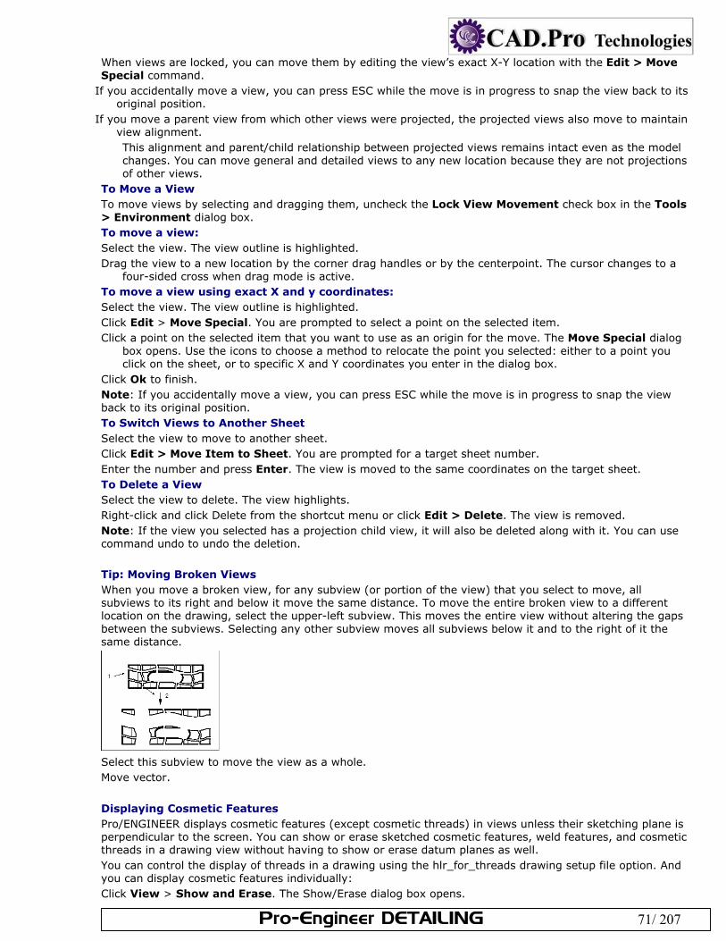
Pro-Engineer DETAILING 71/ 207
When views are locked, you can move them by editing the view’s exact X-Y location with the Edit > Move Special command.
If you accidentally move a view, you can press ESC while the move is in progress to snap the view back to its original position.
If you move a parent view from which other views were projected, the projected views also move to maintain view alignment. This alignment and parent/child relationship between projected views remains intact even as the model changes. You can move general and detailed views to any new location because they are not projections of other views.
To Move a View To move views by selecting and dragging them, uncheck the Lock View Movement check box in the Tools > Environment dialog box. To move a view: Select the view. The view outline is highlighted. Drag the view to a new location by the corner drag handles or by the centerpoint. The cursor changes to a
four-sided cross when drag mode is active. To move a view using exact X and y coordinates: Select the view. The view outline is highlighted. Click Edit > Move Special. You are prompted to select a point on the selected item. Click a point on the selected item that you want to use as an origin for the move. The Move Special dialog
box opens. Use the icons to choose a method to relocate the point you selected: either to a point you click on the sheet, or to specific X and Y coordinates you enter in the dialog box.
Click Ok to finish. Note: If you accidentally move a view, you can press ESC while the move is in progress to snap the view back to its original position. To Switch Views to Another Sheet Select the view to move to another sheet. Click Edit > Move Item to Sheet. You are prompted for a target sheet number. Enter the number and press Enter. The view is moved to the same coordinates on the target sheet. To Delete a View Select the view to delete. The view highlights. Right-click and click Delete from the shortcut menu or click Edit > Delete. The view is removed. Note: If the view you selected has a projection child view, it will also be deleted along with it. You can use command undo to undo the deletion. Tip: Moving Broken Views When you move a broken view, for any subview (or portion of the view) that you select to move, all subviews to its right and below it move the same distance. To move the entire broken view to a different location on the drawing, select the upper-left subview. This moves the entire view without altering the gaps between the subviews. Selecting any other subview moves all subviews below it and to the right of it the same distance.
Select this subview to move the view as a whole. Move vector.
Displaying Cosmetic Features Pro/ENGINEER displays cosmetic features (except cosmetic threads) in views unless their sketching plane is perpendicular to the screen. You can show or erase sketched cosmetic features, weld features, and cosmetic threads in a drawing view without having to show or erase datum planes as well. You can control the display of threads in a drawing using the hlr_for_threads drawing setup file option. And you can display cosmetic features individually: Click View > Show and Erase. The Show/Erase dialog box opens.
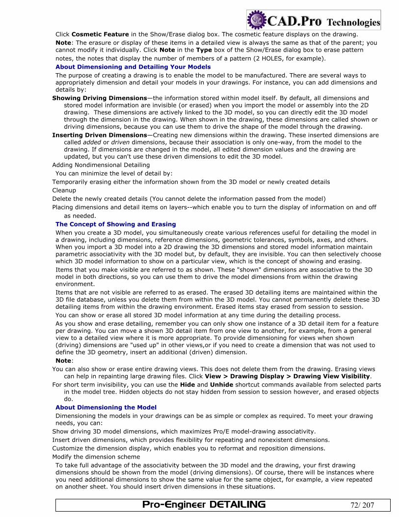
Pro-Engineer DETAILING 72/ 207
Click Cosmetic Feature in the Show/Erase dialog box. The cosmetic feature displays on the drawing. Note: The erasure or display of these items in a detailed view is always the same as that of the parent; you cannot modify it individually. Click Note in the Type box of the Show/Erase dialog box to erase pattern notes, the notes that display the number of members of a pattern (2 HOLES, for example). About Dimensioning and Detailing Your Models The purpose of creating a drawing is to enable the model to be manufactured. There are several ways to appropriately dimension and detail your models in your drawings. For instance, you can add dimensions and details by:
Showing Driving Dimensions—the information stored within model itself. By default, all dimensions and stored model information are invisible (or erased) when you import the model or assembly into the 2D drawing. These dimensions are actively linked to the 3D model, so you can directly edit the 3D model through the dimension in the drawing. When shown in the drawing, these dimensions are called shown or driving dimensions, because you can use them to drive the shape of the model through the drawing.
Inserting Driven Dimensions—Creating new dimensions within the drawing. These inserted dimensions are called added or driven dimensions, because their association is only one-way, from the model to the drawing. If dimensions are changed in the model, all edited dimension values and the drawing are updated, but you can't use these driven dimensions to edit the 3D model.
Adding Nondimensional Detailing You can minimize the level of detail by:
Temporarily erasing either the information shown from the 3D model or newly created details Cleanup Delete the newly created details (You cannot delete the information passed from the model) Placing dimensions and detail items on layers--which enable you to turn the display of information on and off
as needed. The Concept of Showing and Erasing When you create a 3D model, you simultaneously create various references useful for detailing the model in a drawing, including dimensions, reference dimensions, geometric tolerances, symbols, axes, and others. When you import a 3D model into a 2D drawing the 3D dimensions and stored model information maintain parametric associativity with the 3D model but, by default, they are invisible. You can then selectively choose which 3D model information to show on a particular view, which is the concept of showing and erasing. Items that you make visible are referred to as shown. These "shown" dimensions are associative to the 3D model in both directions, so you can use them to drive the model dimensions from within the drawing environment. Items that are not visible are referred to as erased. The erased 3D detailing items are maintained within the 3D file database, unless you delete them from within the 3D model. You cannot permanently delete these 3D detailing items from within the drawing environment. Erased items stay erased from session to session. You can show or erase all stored 3D model information at any time during the detailing process. As you show and erase detailing, remember you can only show one instance of a 3D detail item for a feature per drawing. You can move a shown 3D detail item from one view to another, for example, from a general view to a detailed view where it is more appropriate. To provide dimensioning for views when shown (driving) dimensions are "used up" in other views,or if you need to create a dimension that was not used to define the 3D geometry, insert an additional (driven) dimension. Note:
You can also show or erase entire drawing views. This does not delete them from the drawing. Erasing views can help in repainting large drawing files. Click View > Drawing Display > Drawing View Visibility.
For short term invisibility, you can use the Hide and Unhide shortcut commands available from selected parts in the model tree. Hidden objects do not stay hidden from session to session however, and erased objects do.
About Dimensioning the Model Dimensioning the models in your drawings can be as simple or complex as required. To meet your drawing needs, you can:
Show driving 3D model dimensions, which maximizes Pro/E model-drawing associativity. Insert driven dimensions, which provides flexibility for repeating and nonexistent dimensions. Customize the dimension display, which enables you to reformat and reposition dimensions. Modify the dimension scheme To take full advantage of the associativity between the 3D model and the drawing, your first drawing dimensions should be shown from the model (driving dimensions). Of course, there will be instances where you need additional dimensions to show the same value for the same object, for example, a view repeated on another sheet. You should insert driven dimensions in these situations.
Pro-Engineer DETAILING 73/ 207
Note: You can also add nondimensional detailing, including geometric tolerances, symbols, and text notes. Displaying Dimensions in Detailed and Partial Views A dimension that references nonsolid geometric features (axes, datum points, datum planes, and so forth) can be present in a detailed or partial view only when the following requirements are satisfied:
At least one of the entities being dimensioned must be within the spline boundary. This entity must also be within the view boundary of the view—the view boundary is defined by the solid
geometry of the part. (Nonsolid geometric features are not considered to be solid geometry.) Check that these requirements are met before you change a view to a detailed or partial view, or dimensions will disappear from the new view. The drawing setup file option clip_dimensions affects the display of dimensions in detailed views. When you set it to yes, dimensions that are completely outside of the view boundary do not appear. Dimensions that cross the view boundary appear, and the leader that seems to have no geometric reference appears with a double arrow (>>). To change the arrow style, set the default arrow style of clipped dimensions by specifying a value for the drawing setup file option clip_dim_arrow_style (double_arrow is the default). Saving Dimensions to the Part or Drawing When you create dimensions in Drawing mode, the configuration file option create_drawing_dims_only determines whether the system saves them in the associated part or in the drawing itself. When set to no, (the default), it saves all new model dimensions (not draft dimensions) created in the drawing to the associated part or assembly. Draft dimensions are still saved to the drawing. When set to yes, it saves all new dimensions created in the drawing in the drawing only. The setting should depend on your work scenario. If you are using Intralink, if the dims are stored in the model, the model will be marked as modified and will have to be re-submitted back to intralink. To avoid this every time you reference a model for drawing, you can set the option to yes. Alternately, if you want to use a set draft datum in a GTOL attached to a dimension, the dimension has to be stored in the model, so you would set the option to no. Setting the option only applies to new dimensions created, it does not convert existing dimension. If you need to reset the option for an existing dimension, you will need to recreate it. Tip: Dimensioning Rounds and Revolved Parts The ability to show or insert dimensions for round features depends on the ability to select silhouette edges within drawings. You can select and use the normal dimensioning methods for silhouette edges that:
Lie on a cylinder or cone Lie on a surface of revolution whose axis of revolution is parallel to the screen Lie on a surface of revolution whose axis of revolution is parallel to the screen
In all other cases not listed above, silhouette edges are not selectable. To dimension a round that does not have a selectable silhouette edge, you should sketch a 2D draft curve and then insert the dimension from this curve. About Showing Model Dimensions When you import a 3D model into a 2D drawing the 3D dimensions and stored model information maintain parametric associativity with the 3D model but, by default, they are invisible. You can then selectively choose 3D model information to show on a particular view, which is the concept of showing and erasing. Items that you make visible are referred to as shown. These "shown" dimensions are associative to the 3D model in both directions, so you can use them to drive the model dimensions from within the drawing environment. While showing model dimensions and detailing, items may overlap on the drawing. If this occurs, you can pause the show and erase tool and move the drawing items to enable you to see and correctly select the items to show or erase. After you place the model dimensions and detailing on the drawing you can adjust their positions on the sheet and customize the format. Consider the following when you show model dimensions and detailing in your Pro/E drawings:
Only one driving dimension for each model dimension may exist in a drawing. A drawing may have several views of the same object, but only one driving dimension for each feature of the model may be shown. It is possible to unintentionally edit the model. If a driving dimension is edited, it turns white in color as a warning that there is a discrepancy between the drawing and the model. When you regenerate the model, the drawing accepts the new dimension. It is possible, using configuration options, to break the link between model and drawing, but this is not the usual Pro/Engineer usage.
To Show Dimensions from the 3D Model
Pro-Engineer DETAILING 74/ 207
You can show the dimensions that have been passed to the drawing from the 3D model. Remember, only one instance of a driving dimension may be shown per drawing file. If you need to repeat these dimensions on other sheets, insert (driven) dimensions. Click View > Show and Erase. The Show/Erase dialog box opens. Click Show. Under Type, indicate which type of dimension to show, or both types:
—Display the normal model dimensions.
—Display reference dimensions. Use the options tab to filter what dimensions you want to show up in the drawing:
Erased—Show previously erased items. Never Shown—Show items that you have yet to show in the drawing. Switch to Ordinate—Convert linear dimensions to display as ordinate. Under Show By define where you want to display the dimensions:
Feature—Show the dimensions for a particular feature on the drawing. Part—Show the dimensions for a particular part on the drawing. View—Show all the dimensions for the features and parts within a particular drawing view. Feature and View—Show the dimensions for a feature that repeats in several views in one selected view. For
example, if you have a feature to dimension that shows in several projection views, you can use the Feature and View button to click the feature in the view in which you want to show it.
Part and View—Show the dimensions for a part that repeats in several views in one selected view. Show All—Show all the dimensions within the drawing. Select the appropriate feature, part, or view to display the dimensions. You may need to repaint the drawing
for the dimensions to display. When the dimensions display the Preview tab opens. Of the dimensions previewed on the drawing, there may be some that you do not want to show. You can
filter these dimensions using the preview tab: Sel to Keep—Select the individual dimensions to show in the drawing. Any dimensions not selected will be
erased. Sel to Remove—Select dimensions to remove from the drawing. Any dimensions not selected will remain in
the drawing. Accept All—Keep all the previewed dimensions. Erase All—Erase all the previewed dimensions.
While showing the dimensions, items may overlap on the drawing. If this occurs, you can pause the show and erase tool and move the drawing items to enable you to see and correctly select the items to show or erase. Right-click anywhere on the drawing and click Pause Show and Erase. Then move the drawing items within the view as necessary. Before continuing with the show and erase process, you must right-click and Resume Show and Erase. If you need to select multiple dimensions to keep or remove, you can either use CTRL or region selection. If you do not select all the necessary items at this time you will have to repeat the show and erase process again.
When you are finished with the preview, click OK in the Select dialog box. The dimensions are shown. Click Close to close the Show and Erase dialog box. Note: The show_preview_default drawing setup file option lets you set the preview tab default to either select to keep or select to remove. To Show Dimensions in an Assembly Drawing In assembly drawings, you can display the parameters of assembly features and all assembly components; however, you cannot show the dimensions of subassemblies. The dimensions in an assembly drawing are visible only at the assembly level. You must have the assembly from which a drawing was created in session in order for the dimensions to appear for modification. Click View > Show and Erase. The Show/Erase dialog box opens. Click Show. Under Type, indicate which type of dimension to show, or both types:
—Display the normal model dimensions.
—Display reference dimensions. Define where you want you want to display the dimensions:
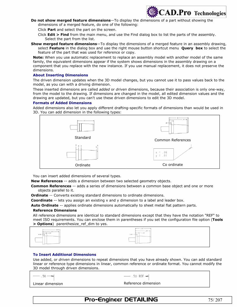
Pro-Engineer DETAILING 75/ 207
Do not show merged feature dimensions—To display the dimensions of a part without showing the dimensions of a merged feature, do one of the following: Click Part and select the part on the screen. Click Edit > Find from the main menu, and use the Find dialog box to list the parts of the assembly.
Select the part from the list. Show merged feature dimensions—To display the dimensions of a merged feature in an assembly drawing,
select Feature in the dialog box and uae the right mouse button shortcut menu Query box to select the feature of the part that was used for reference or copy.
Note: When you use automatic replacement to replace an assembly model with another model of the same family, the equivalent dimensions appear if the system shows dimensions in the assembly drawing on a component that you replace with the new instance. If you use manual replacement, it does not preserve the dimensions. About Inserting Dimensions The driven dimension updates when the 3D model changes, but you cannot use it to pass values back to the model, as you can with a driving dimension. These inserted dimensions are called added or driven dimensions, because their association is only one-way, from the model to the drawing. If dimensions are changed in the model, all edited dimension values and the drawing are updated, but you can't use these driven dimensions to edit the 3D model. Formats of Added Dimensions Added dimensions also let you apply different drafting-specific formats of dimensions than would be used in 3D. You can add dimension in the following types:
Standard
Common References
Ordinate
Co ordinate
You can insert added dimensions of several types.
New References -- adds a dimension between two selected geometry objects. Common References -- adds a series of dimensions between a common base object and one or more
objects parallel to it. Ordinate -- Converts existing standard dimensions to ordinate dimensions. Coordinate -- lets you assign an existing x and y dimension to a label and leader box. Auto Ordinate -- applies ordinate dimensions automatically to sheet metal flat pattern parts. Reference Dimensions All reference dimensions are identical to standard dimensions except that they have the notation "REF" to meet ISO requirements. You can enclose them in parentheses if you set the configuration file option (Tools > Options) parenthesize_ref_dim to yes.
To Insert Additional Dimensions Use added, or driven dimensions to repeat dimensions that you have already shown. You can add standard linear or reference type dimensions in linear, common reference or ordinate format. You cannot modify the 3D model through driven dimensions.
Linear dimension
Reference dimension
Pro-Engineer DETAILING 76/ 207
Click Insert > Dimension or Reference Dimension. Use the fly-out menus to specify use of New References, a Common Reference, or an Ordinate dimension. The ATTACH TYPE menu appears on the menu manager. Select an edge, an edge and point, two points, or a vertex using the ATTACH TYPE menu commands:
On Entity—Attaches the dimension to the entity at the pick point, according to the rules of creating regular dimensions.
Midpoint—Attaches the dimension to the midpoint of the selected entity. Center—Attaches the dimension to the center of a circular edge. Circular edges include circular geometry
(holes, rounds, curves, surfaces, and so forth) and circular draft entities. If you select a noncircular entity, attaches the dimension to the entity, as does On Entity.
Intersect—Attaches the dimension to the closest intersection point of two selected entities. Make Line—References the current x- and y-axes in the orientation of the view of the model.
Note: To create a driven dimension of an arc length , select the ends and the middle of an arc; then choose ARC DIM TYPE > Arc Length.
Click the beginning and ending references for the dimension. If you have selected two arcs or circles, use the ARC PNT TYPE menu to do one of the following:
Click Center to create a dimension between the centers of the arcs, ellipses, or circles. Click Tangent to create a dimension between the circle, arc, or ellipse edges—the tangency closest to where
you selected. Middle-click to complete the dimension. You are still in dimensioning mode and you may create another
dimension. To Insert a Reference Dimension Use added, or driven dimensions to enter dimensions with a reference notation. You can add reference dimensions in linear, common reference or ordinate format. (You cannot modify the 3D model through driven dimensions. )
Linear dimension
Reference dimension
Click Insert > Reference Dimension. Use the fly-out menus to specify use of New References, a Common Reference, or an Ordinate dimension. The ATTACH TYPE menu appears on the Menu Manager.
Select an edge, an edge and point, two points, or a vertex using the ATTACH TYPE menu commands: On Entity—Attaches the dimension to the entity at the pick point, according to the rules of creating
regular dimensions. Midpoint—Attaches the dimension to the midpoint of the selected entity. Center—Attaches the dimension to the center of a circular edge. Circular edges include circular geometry
(holes, rounds, curves, surfaces, and so forth) and circular draft entities. If you select a noncircular entity, attaches the dimension to the entity, as does On Entity.
Intersect—Attaches the dimension to the closest intersection point of two selected entities. Make Line—References the current x- and y-axes in the orientation of the view of the model. Note: To create a driven dimension of an arc length , select the ends and the middle of an arc; then choose ARC DIM TYPE > Arc Length.
Click the beginning and ending references for the dimension. If you have selected two arcs or circles, use the ARC PNT TYPE menu to do one of the following:
Click Center to create a dimension between the centers of the arcs, ellipses, or circles. Click Tangent to create a dimension between the circle, arc, or ellipse edges—the tangency closest to
where you selected. Middle click to complete the dimension. You are still in dimensioning mode and you may create another
dimension. To Insert Dimensions from a Common Reference Click Insert > Dimension or Reference Dimension, then Common Reference. Click the line to use for the common reference. It highlights in magenta. Click the line to use for the first dimension. Middle click to place the dimension. You are still in dimension
mode, referencing the common dimension. Click the line for the second dimension. Middle click to complete. Proceed this way until you have entered all the common reference dimensions, then middle click to exit. Dimensions from a common reference.
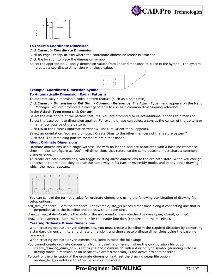
Pro-Engineer DETAILING 77/ 207
To Insert a Coordinate Dimension Click Insert > Coordinate Dimension. Click an edge, entity, or axis where the coordinate dimension leader is attached. Click the location to place the dimension symbol. Select the appropriate x- and y-dimension values from linear dimensions to place in the symbol. The system
creates a coordinate dimension with these values.
Example: Coordinate Dimension Symbol To Automatically Dimension Radial Patterns To automatically dimension a radial pattern feature (such as a bolt circle): Click Insert > Dimension or Ref Dim > Common Reference. The Attach Type menu appears on the Menu
Manager. You are prompted "Select geometry to use as a common dimensioning reference." In the Attach Type menu click Center. Select the axis of one of the pattern features. You are prompted to select additional entities to dimension. Select the base point to dimension against. For example, you can select a csys at the center of the pattern or
an entity outside of the pattern. Click OK in the Select Confirmation window. The Dim Orient menu appears. Select an orientation. You are prompted: Create Dims to the other members of the feature pattern? Click Yes. The remaining pattern members are dimensioned. About Ordinate Dimensions Ordinate dimensions use a single witness line with no leader, and are associated with a baseline reference, shown in the next figure as ".00". All dimensions that reference the same baseline must share a common plane or edge. To create ordinate dimensions, you toggle existing linear dimensions to the ordinate state. When you change dimensions to ordinate, they appear the same way in 3D Part or Assembly mode, and in any other drawing in which the model appears.
You can control the format display for ordinate dimensions using the following combination of drawing file setup options:
ord_dim_standard—Sets the standard. For example, std_jis places dimensions along a connecting line that is perpendicular to the baseline and starts with an open circle.
draw_arrow_style—Controls the style of the arrow and circle—whether they are open, closed, or filled. draw_dot_diameter—Sets the diameter for the leader line dots (the circle on the baseline). Creating Ordinate Driven Dimensions When creating ordinate driven dimensions, you must create a baseline in the required direction by converting a standard dimension into an ordinate dimension, and then create ordinate dimensions using the baseline reference. When creating ordinate driven dimensions, keep in mind the following:
You cannot create ordinate dimensions from a baseline dimension when the configuration file option create_drawing_dims_only is set to yes and a dimension with a d or ad type symbol (denoting either a driving model dimension or an associative draft dimension) is the active ordinate baseline.
To control the orientation of the ordinate dimension text, set the drawing setup file option orddim_text_orientation to either parallel or horizontal.
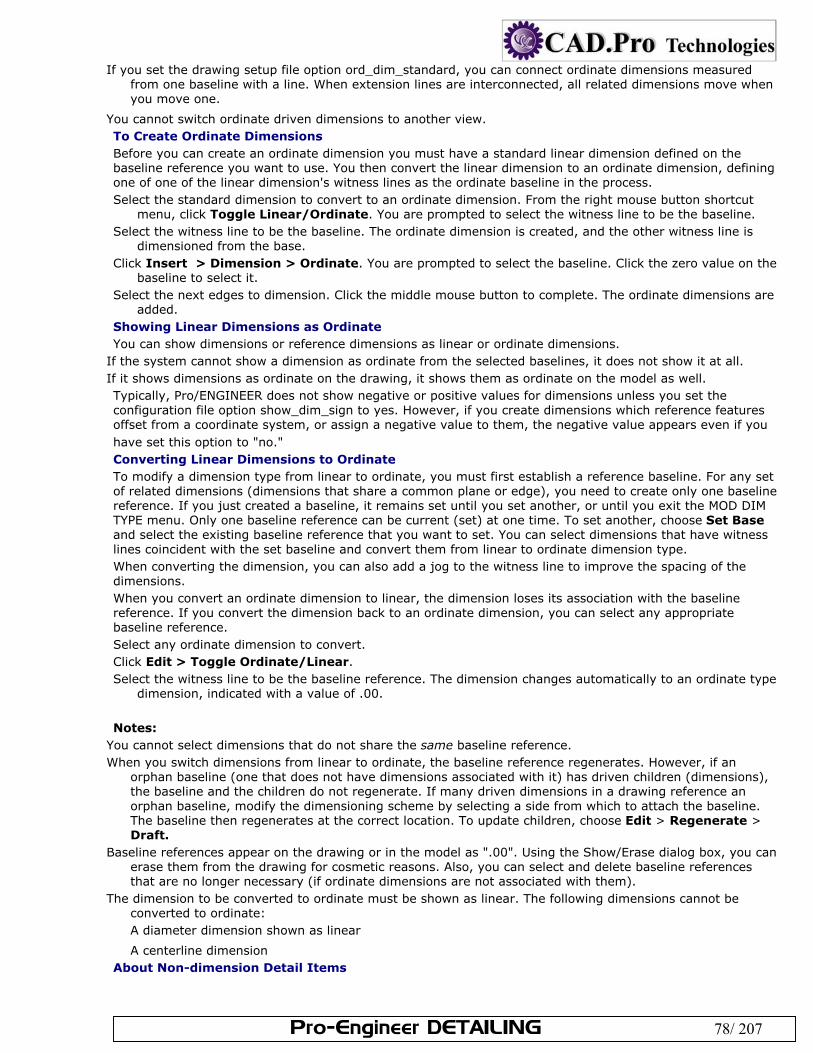
Pro-Engineer DETAILING 78/ 207
If you set the drawing setup file option ord_dim_standard, you can connect ordinate dimensions measured from one baseline with a line. When extension lines are interconnected, all related dimensions move when you move one.
You cannot switch ordinate driven dimensions to another view. To Create Ordinate Dimensions Before you can create an ordinate dimension you must have a standard linear dimension defined on the baseline reference you want to use. You then convert the linear dimension to an ordinate dimension, defining one of one of the linear dimension's witness lines as the ordinate baseline in the process. Select the standard dimension to convert to an ordinate dimension. From the right mouse button shortcut
menu, click Toggle Linear/Ordinate. You are prompted to select the witness line to be the baseline. Select the witness line to be the baseline. The ordinate dimension is created, and the other witness line is
dimensioned from the base. Click Insert > Dimension > Ordinate. You are prompted to select the baseline. Click the zero value on the
baseline to select it. Select the next edges to dimension. Click the middle mouse button to complete. The ordinate dimensions are
added. Showing Linear Dimensions as Ordinate You can show dimensions or reference dimensions as linear or ordinate dimensions.
If the system cannot show a dimension as ordinate from the selected baselines, it does not show it at all. If it shows dimensions as ordinate on the drawing, it shows them as ordinate on the model as well. Typically, Pro/ENGINEER does not show negative or positive values for dimensions unless you set the configuration file option show_dim_sign to yes. However, if you create dimensions which reference features offset from a coordinate system, or assign a negative value to them, the negative value appears even if you have set this option to "no." Converting Linear Dimensions to Ordinate To modify a dimension type from linear to ordinate, you must first establish a reference baseline. For any set of related dimensions (dimensions that share a common plane or edge), you need to create only one baseline reference. If you just created a baseline, it remains set until you set another, or until you exit the MOD DIM TYPE menu. Only one baseline reference can be current (set) at one time. To set another, choose Set Base and select the existing baseline reference that you want to set. You can select dimensions that have witness lines coincident with the set baseline and convert them from linear to ordinate dimension type. When converting the dimension, you can also add a jog to the witness line to improve the spacing of the dimensions. When you convert an ordinate dimension to linear, the dimension loses its association with the baseline reference. If you convert the dimension back to an ordinate dimension, you can select any appropriate baseline reference. Select any ordinate dimension to convert. Click Edit > Toggle Ordinate/Linear. Select the witness line to be the baseline reference. The dimension changes automatically to an ordinate type
dimension, indicated with a value of .00. Notes:
You cannot select dimensions that do not share the same baseline reference. When you switch dimensions from linear to ordinate, the baseline reference regenerates. However, if an
orphan baseline (one that does not have dimensions associated with it) has driven children (dimensions), the baseline and the children do not regenerate. If many driven dimensions in a drawing reference an orphan baseline, modify the dimensioning scheme by selecting a side from which to attach the baseline. The baseline then regenerates at the correct location. To update children, choose Edit > Regenerate > Draft.
Baseline references appear on the drawing or in the model as ".00". Using the Show/Erase dialog box, you can erase them from the drawing for cosmetic reasons. Also, you can select and delete baseline references that are no longer necessary (if ordinate dimensions are not associated with them).
The dimension to be converted to ordinate must be shown as linear. The following dimensions cannot be converted to ordinate: A diameter dimension shown as linear
A centerline dimension About Non-dimension Detail Items
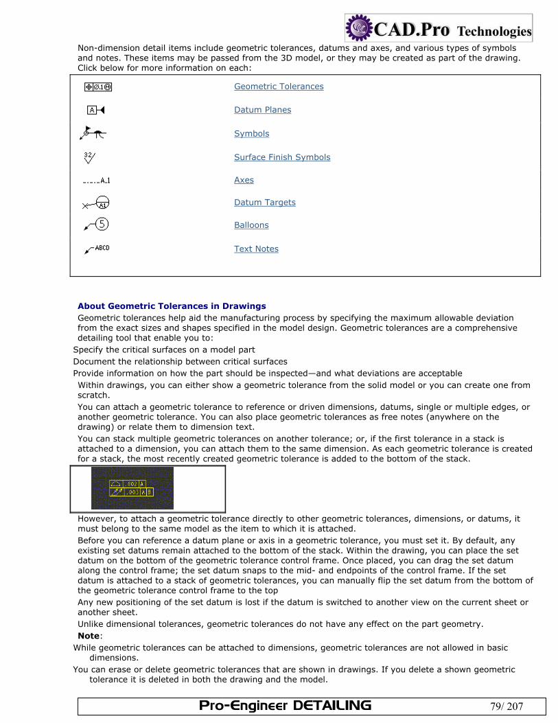
Pro-Engineer DETAILING 79/ 207
Non-dimension detail items include geometric tolerances, datums and axes, and various types of symbols and notes. These items may be passed from the 3D model, or they may be created as part of the drawing. Click below for more information on each:
Geometric Tolerances
Datum Planes
Symbols
Surface Finish Symbols
Axes
Datum Targets
Balloons
Text Notes
About Geometric Tolerances in Drawings Geometric tolerances help aid the manufacturing process by specifying the maximum allowable deviation from the exact sizes and shapes specified in the model design. Geometric tolerances are a comprehensive detailing tool that enable you to:
Specify the critical surfaces on a model part Document the relationship between critical surfaces Provide information on how the part should be inspected—and what deviations are acceptable Within drawings, you can either show a geometric tolerance from the solid model or you can create one from scratch. You can attach a geometric tolerance to reference or driven dimensions, datums, single or multiple edges, or another geometric tolerance. You can also place geometric tolerances as free notes (anywhere on the drawing) or relate them to dimension text. You can stack multiple geometric tolerances on another tolerance; or, if the first tolerance in a stack is attached to a dimension, you can attach them to the same dimension. As each geometric tolerance is created for a stack, the most recently created geometric tolerance is added to the bottom of the stack.
However, to attach a geometric tolerance directly to other geometric tolerances, dimensions, or datums, it must belong to the same model as the item to which it is attached. Before you can reference a datum plane or axis in a geometric tolerance, you must set it. By default, any existing set datums remain attached to the bottom of the stack. Within the drawing, you can place the set datum on the bottom of the geometric tolerance control frame. Once placed, you can drag the set datum along the control frame; the set datum snaps to the mid- and endpoints of the control frame. If the set datum is attached to a stack of geometric tolerances, you can manually flip the set datum from the bottom of the geometric tolerance control frame to the top Any new positioning of the set datum is lost if the datum is switched to another view on the current sheet or another sheet. Unlike dimensional tolerances, geometric tolerances do not have any effect on the part geometry. Note:
While geometric tolerances can be attached to dimensions, geometric tolerances are not allowed in basic dimensions.
You can erase or delete geometric tolerances that are shown in drawings. If you delete a shown geometric tolerance it is deleted in both the drawing and the model.
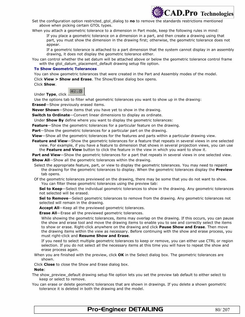
Pro-Engineer DETAILING 80/ 207
Set the configuration option restricted_gtol_dialog to no to remove the standards restrictions mentioned above when picking certain GTOL types.
When you attach a geometric tolerance to a dimension in Part mode, keep the following rules in mind: If you place a geometric tolerance on a dimension in a part, and then create a drawing using that part, you must show the dimension in the drawing first; otherwise, the geometric tolerance does not appear. If a geometric tolerance is attached to a part dimension that the system cannot display in an assembly drawing, it does not display the geometric tolerance either.
You can control whether the set datum will be attached above or below the geometric tolerance control frame with the gtol_datum_placement_default drawing setup file option.
To Show Geometric Tolerances You can show geometric tolerances that were created in the Part and Assembly modes of the model. Click View > Show and Erase. The Show/Erase dialog box opens. Click Show.
Under Type, click . Use the options tab to filter what geometric tolerances you want to show up in the drawing:
Erased—Show previously erased items. Never Shown—Show items that you have yet to show in the drawing. Switch to Ordinate—Convert linear dimensions to display as ordinate. Under Show By define where you want to display the geometric tolerances:
Feature—Show the geometric tolerances for a particular feature on the drawing. Part—Show the geometric tolerances for a particular part on the drawing. View—Show all the geometric tolerances for the features and parts within a particular drawing view. Feature and View—Show the geometric tolerances for a feature that repeats in several views in one selected
view. For example, if you have a feature to dimension that shows in several projection views, you can use the Feature and View button to click the feature in the view in which you want to show it.
Part and View—Show the geometric tolerances for a part that repeats in several views in one selected view. Show All—Show all the geometric tolerances within the drawing. Select the appropriate feature, part, or view to display the geometric tolerances. You may need to repaint
the drawing for the geometric tolerances to display. When the geometric tolerances display the Preview tab opens.
Of the geometric tolerances previewed on the drawing, there may be some that you do not want to show. You can filter these geometric tolerances using the preview tab:
Sel to Keep—Select the individual geometric tolerances to show in the drawing. Any geometric tolerances not selected will be erased. Sel to Remove—Select geometric tolerances to remove from the drawing. Any geometric tolerances not selected will remain in the drawing. Accept All—Keep all the previewed geometric tolerances. Erase All—Erase all the previewed geometric tolerances. While showing the geometric tolerances, items may overlap on the drawing. If this occurs, you can pause the show and erase tool and move the drawing items to enable you to see and correctly select the items to show or erase. Right-click anywhere on the drawing and click Pause Show and Erase. Then move the drawing items within the view as necessary. Before continuing with the show and erase process, you must right-click and Resume Show and Erase. If you need to select multiple geometric tolerances to keep or remove, you can either use CTRL or region selection. If you do not select all the necessary items at this time you will have to repeat the show and erase process again.
When you are finished with the preview, click OK in the Select dialog box. The geometric tolerances are shown.
Click Close to close the Show and Erase dialog box. Note:
The show_preview_default drawing setup file option lets you set the preview tab default to either select to keep or select to remove.
You can erase or delete geometric tolerances that are shown in drawings. If you delete a shown geometric tolerance it is deleted in both the drawing and the model.
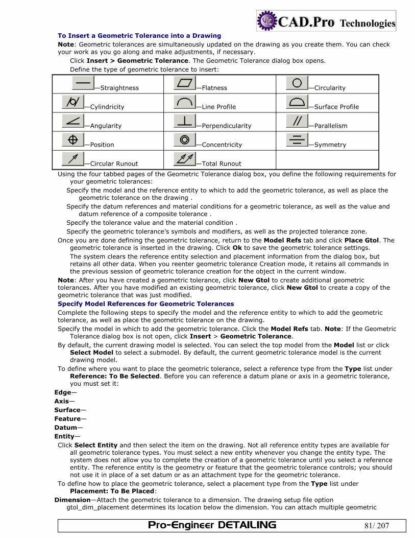
Pro-Engineer DETAILING 81/ 207
To Insert a Geometric Tolerance into a Drawing Note: Geometric tolerances are simultaneously updated on the drawing as you create them. You can check your work as you go along and make adjustments, if necessary.
Click Insert > Geometric Tolerance. The Geometric Tolerance dialog box opens. Define the type of geometric tolerance to insert:
—Straightness —Flatness —Circularity
—Cylindricity —Line Profile —Surface Profile
—Angularity —Perpendicularity —Parallelism
—Position —Concentricity —Symmetry
—Circular Runout —Total Runout
Using the four tabbed pages of the Geometric Tolerance dialog box, you define the following requirements for your geometric tolerances:
Specify the model and the reference entity to which to add the geometric tolerance, as well as place the geometric tolerance on the drawing .
Specify the datum references and material conditions for a geometric tolerance, as well as the value and datum reference of a composite tolerance .
Specify the tolerance value and the material condition . Specify the geometric tolerance’s symbols and modifiers, as well as the projected tolerance zone.
Once you are done defining the geometric tolerance, return to the Model Refs tab and click Place Gtol. The geometric tolerance is inserted in the drawing. Click Ok to save the geometric tolerance settings. The system clears the reference entity selection and placement information from the dialog box, but retains all other data. When you reenter geometric tolerance Creation mode, it retains all commands in the previous session of geometric tolerance creation for the object in the current window.
Note: After you have created a geometric tolerance, click New Gtol to create additional geometric tolerances. After you have modified an existing geometric tolerance, click New Gtol to create a copy of the geometric tolerance that was just modified. Specify Model References for Geometric Tolerances Complete the following steps to specify the model and the reference entity to which to add the geometric tolerance, as well as place the geometric tolerance on the drawing. Specify the model in which to add the geometric tolerance. Click the Model Refs tab. Note: If the Geometric
Tolerance dialog box is not open, click Insert > Geometric Tolerance. By default, the current drawing model is selected. You can select the top model from the Model list or click
Select Model to select a submodel. By default, the current geometric tolerance model is the current drawing model.
To define where you want to place the geometric tolerance, select a reference type from the Type list under Reference: To Be Selected. Before you can reference a datum plane or axis in a geometric tolerance, you must set it:
Edge— Axis— Surface— Feature— Datum— Entity— Click Select Entity and then select the item on the drawing. Not all reference entity types are available for
all geometric tolerance types. You must select a new entity whenever you change the entity type. The system does not allow you to complete the creation of a geometric tolerance until you select a reference entity. The reference entity is the geometry or feature that the geometric tolerance controls; you should not use it in place of a set datum or as an attachment type for the geometric tolerance.
To define how to place the geometric tolerance, select a placement type from the Type list under Placement: To Be Placed:
Dimension—Attach the geometric tolerance to a dimension. The drawing setup file option gtol_dim_placement determines its location below the dimension. You can attach multiple geometric
Pro-Engineer DETAILING 82/ 207
tolerances (stacked) to the same dimension, and they behave as a single tolerance when you manipulate the dimension symbol.
As Free Note—Place the geometric tolerance anywhere on the drawing. In Part mode, you cannot display free geometric tolerances that were created in Drawing mode. You can use Free Note placement only when you select the drawing as the top model from the Model list.
Leader—Attach the geometric tolerance to multiple edges (including datum quilt edges) with leader lines or to dimension witness lines.
Tangent Leader—Attach the geometric tolerance to an edge along a leader line that is tangent to the selected edge, orienting the geometric tolerance text box at the same angle as the leader.
Normal Leader—Attach the geometric tolerance to an edge along a leader line that is perpendicular to the selected edge.
Other Gtol—Attach the new geometric tolerance to an existing one (you cannot attach the existing geometric tolerance to a dimension).
Make Dim—Create a driven dimension and attaches the dimension to it. This dimension belongs to the drawing. The geometric tolerance appears in standard dimension format, but with the geometric tolerance instead of a dimension value.
Offset— If you do not need to define additional datum references, tolerance values, or symbols, click Place Gtol. The
geometric tolerance is inserted in the drawing. Otherwise, continue defining the geometric tolerance: Define Datum References for Geometric Tolerances Complete the following to specify the datum references and material conditions for a geometric tolerance, as well as the value and datum reference of a composite tolerance. To define datum references for a geometric tolerance that permits datum references, click the Datum Refs
tab. Note: If the Geometric Tolerance dialog box is not open, click Insert > Geometric Tolerance. Select and define the Primary, Secondary, and Tertiary references as necessary. The lists contain the
currently selected datum and all other datums in the current geometric tolerance model. Click to select another set datum or axis. You can assign a material condition to the reference by selecting a symbol from the list next to the basic or compound reference:
LMC—Least material condition
MMC—Maximum material condition
RFS (with symbol)—Regardless of feature size
RFS (no symbol)—RFS, but does not show a symbol in frame The references do not need to follow the order prescribed by the primary, secondary, or tertiary tabs. Click Unordered to allow two datum references to be listed in the same section of the control frame.
To define a composite tolerance, click Composite Tolerance. Type a tolerance in the Value box and select the desired datum from the Datum Reference list:
None— Primary— Secondary—
Tertiary— Set Tolerance Values for Geometric Tolerances Complete the following to specify the tolerance value and the material condition. To specify the overall and per unit tolerance values assigned to the geometric tolerance, click the Tol Value
tab. Note: If the Geometric Tolerance dialog box is not open, click Insert > Geometric Tolerance. To show only the geometric tolerance, without indicating any restricted length, type a value for the geometric
tolerance in the Overall Tolerance box. Designate a name for the tolerance. The name displays...? If you are restricting the length to which the tolerance applies, select Per Unit Tolerance. Type a
Value/Unit and define a unit length. Assign a material condition symbol for the geometric tolerance: Select the desired symbol from the Material Condition list:
LMC—Least material condition
MMC—Maximum material condition
RFS (with symbol)—Regardless of feature size
Pro-Engineer DETAILING 83/ 207
RFS (no symbol)—RFS, but does not show a symbol in frame Designate Symbols for Geometric Tolerances Complete the following to specify the geometric tolerance’s symbols and modifiers, as well as the projected tolerance zone. To designate a symbol for the geometric tolerance, click the Symbols tab. Note: If the Geometric Tolerance
dialog box is not open, click Insert > Geometric Tolerance. Specify the symbols and modifiers to make available by selecting the appropriate check boxes under
Symbols and Modifiers: Statistical Tolerance— Diameter Tolerance— Free State— All Around Symbol— Tangent Plane— Set Boundary—
Note: If you want to create additional text to the right of the symbol, select Additional Text on right. Type the desired text in the box.
To establish a projected tolerance zone, select the appropriate option under Projected Tolerance Zone: None—Do not specify a projected tolerance zone Below Gtol—Indicate the projected tolerance zone without specifying the height, placing it on a separate line
below the geometric tolerance Inside Gtol—Indicate the projected tolerance zone without specifying the height, placing it on the same line
next to the geometric tolerance Profile Boundary—(available for Profile gtols only) Specify a unilateral direction, bilateral direction, or both.
The Flip side allows you to modify the profile direction. Note: You can also specify the height of the projected tolerance zone by selecting Zone Height, and typing a value in the box.
Creating Geometric Tolerances in Assembly Drawings In assembly drawings you can insert geometric tolerances in the top-level assembly, the subassembly, or in a part. When you create a geometric tolerance in the top-level model (that is, a part in a part drawing or top assembly in an assembly drawing) the system associates the tolerance with the view in which you have selected a reference entity. Reference datums that you specify for the geometric tolerance must belong to the same top-level model; however, you can select them in any view. You cannot reference draft entities and draft datums. Geometric tolerances applied to draft entities (draft geometric tolerances) can reference datums of the model. You can attach an assembly geometric tolerance to a dimension, datum, or another geometric tolerance, provided they both belong to the same assembly. To Insert a Geometric Tolerance in an Assembly Drawing Click Insert > Geometric Tolerance. The Geometric Tolerance dialog box opens. Define the type of geometric tolerance to insert. On the Model Refs tab, specify the assembly in the Model list. Continue defining the geometric tolerance as
would any other: To Insert a Geometric Tolerance into a Drawing Note: When you create a geometric tolerance in an assembly drawing, if you set the draw_models_read_only configuration file option:
Yes—Sets the Drawing command as the default in the Model list of the Model Refs page of the Geometric Tolerance dialog box. The Part and Assembly commands are not available for selection; if you choose them, an error message appears.
No—If there are no assembly views on the current page, the Part command is the default in the Model list. If an assembly view is present, Assembly is the default.
Example: Geometric Tolerance Classes and Types
Class Type Symbol Reference Entity
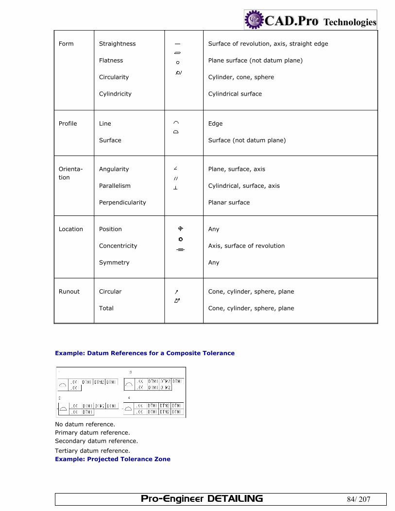
Pro-Engineer DETAILING 84/ 207
Form
Straightness Flatness Circularity Cylindricity
Surface of revolution, axis, straight edge Plane surface (not datum plane) Cylinder, cone, sphere Cylindrical surface
Profile
Line Surface
Edge Surface (not datum plane)
Orienta- tion
Angularity Parallelism Perpendicularity
Plane, surface, axis Cylindrical, surface, axis Planar surface
Location
Position Concentricity Symmetry
Any Axis, surface of revolution Any
Runout
Circular Total
Cone, cylinder, sphere, plane Cone, cylinder, sphere, plane
Example: Datum References for a Composite Tolerance
No datum reference. Primary datum reference. Secondary datum reference.
Tertiary datum reference. Example: Projected Tolerance Zone
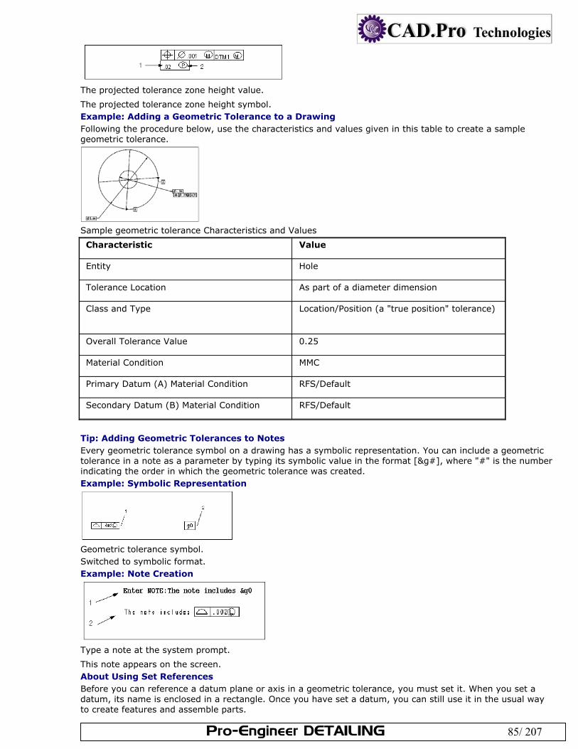
Pro-Engineer DETAILING 85/ 207
The projected tolerance zone height value.
The projected tolerance zone height symbol. Example: Adding a Geometric Tolerance to a Drawing Following the procedure below, use the characteristics and values given in this table to create a sample geometric tolerance.
Sample geometric tolerance Characteristics and Values
Characteristic Value
Entity Hole
Tolerance Location As part of a diameter dimension
Class and Type Location/Position (a "true position" tolerance)
Overall Tolerance Value 0.25
Material Condition MMC
Primary Datum (A) Material Condition RFS/Default
Secondary Datum (B) Material Condition RFS/Default
Tip: Adding Geometric Tolerances to Notes Every geometric tolerance symbol on a drawing has a symbolic representation. You can include a geometric tolerance in a note as a parameter by typing its symbolic value in the format [&g#], where "#" is the number indicating the order in which the geometric tolerance was created. Example: Symbolic Representation
Geometric tolerance symbol. Switched to symbolic format. Example: Note Creation
Type a note at the system prompt.
This note appears on the screen. About Using Set References Before you can reference a datum plane or axis in a geometric tolerance, you must set it. When you set a datum, its name is enclosed in a rectangle. Once you have set a datum, you can still use it in the usual way to create features and assemble parts.
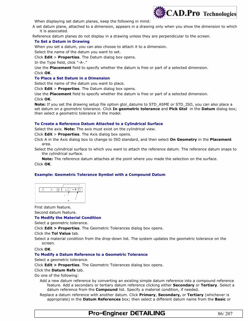
Pro-Engineer DETAILING 86/ 207
When displaying set datum planes, keep the following in mind: A set datum plane, attached to a dimension, appears in a drawing only when you show the dimension to which
it is associated. Reference datum planes do not display in a drawing unless they are perpendicular to the screen. To Set a Datum in Drawing When you set a datum, you can also choose to attach it to a dimension. Select the name of the datum you want to set. Click Edit > Properties. The Datum dialog box opens. In the Type field, click "-A-." Use the Placement field to specify whether the datum is free or part of a selected dimension. Click OK. To Place a Set Datum in a Dimension Select the name of the datum you want to place. Click Edit > Properties. The Datum dialog box opens. Use the Placement field to specify whether the datum is free or part of a selected dimension. Click OK. Note: If you set the drawing setup file option gtol_datums to STD_ASME or STD_ISO, you can also place a set datum on a geometric tolerance. Click In geometric tolerance and Pick Gtol in the Datum dialog box; then select a geometric tolerance in the model. To Create a Reference Datum Attached to a Cylindrical Surface Select the axis. Note: The axis must exist on the cylindrical view. Click Edit > Properties. The Axis dialog box opens. Click A in the Axis dialog box to change to ISO standard, and then select On Geometry in the Placement
area. Select the cylindrical surface to which you want to attach the reference datum. The reference datum snaps to
the cylindrical surface. Note: The reference datum attaches at the point where you made the selection on the surface.
Click OK. Example: Geometric Tolerance Symbol with a Compound Datum
First datum feature. Second datum feature. To Modify the Material Condition Select a geometric tolerance. Click Edit > Properties. The Geometric Tolerances dialog box opens. Click the Tol Value tab. Select a material condition from the drop-down list. The system updates the geometric tolerance on the
screen.
Click OK. To Modify a Datum Reference to a Geometric Tolerance Select a geometric tolerance. Click Edit > Properties. The Geometric Tolerances dialog box opens. Click the Datum Refs tab. Do one of the following:
Add a new datum reference by converting an existing simple datum reference into a compound reference feature. Add a secondary or tertiary datum reference clicking either Secondary or Tertiary. Select a datum reference from the Compound list. Specify a material condition, if needed.
Replace a datum reference with another datum. Click Primary, Secondary, or Tertiary (whichever is appropriate) in the Datum References box; then select a different datum name from the Basic or
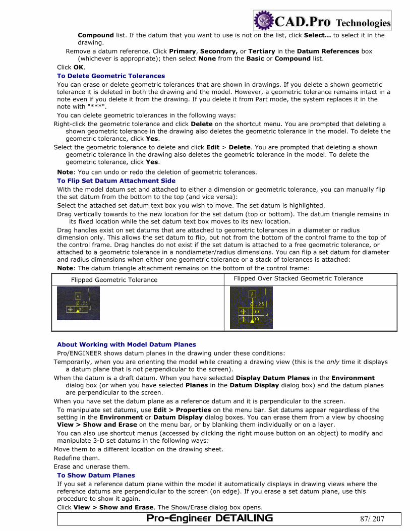
Pro-Engineer DETAILING 87/ 207
Compound list. If the datum that you want to use is not on the list, click Select... to select it in the drawing.
Remove a datum reference. Click Primary, Secondary, or Tertiary in the Datum References box (whichever is appropriate); then select None from the Basic or Compound list.
Click OK. To Delete Geometric Tolerances You can erase or delete geometric tolerances that are shown in drawings. If you delete a shown geometric tolerance it is deleted in both the drawing and the model. However, a geometric tolerance remains intact in a note even if you delete it from the drawing. If you delete it from Part mode, the system replaces it in the note with "***". You can delete geometric tolerances in the following ways:
Right-click the geometric tolerance and click Delete on the shortcut menu. You are prompted that deleting a shown geometric tolerance in the drawing also deletes the geometric tolerance in the model. To delete the geometric tolerance, click Yes.
Select the geometric tolerance to delete and click Edit > Delete. You are prompted that deleting a shown geometric tolerance in the drawing also deletes the geometric tolerance in the model. To delete the geometric tolerance, click Yes.
Note: You can undo or redo the deletion of geometric tolerances. To Flip Set Datum Attachment Side With the model datum set and attached to either a dimension or geometric tolerance, you can manually flip the set datum from the bottom to the top (and vice versa): Select the attached set datum text box you wish to move. The set datum is highlighted. Drag vertically towards to the new location for the set datum (top or bottom). The datum triangle remains in
its fixed location while the set datum text box moves to its new location. Drag handles exist on set datums that are attached to geometric tolerances in a diameter or radius dimension only. This allows the set datum to flip, but not from the bottom of the control frame to the top of the control frame. Drag handles do not exist if the set datum is attached to a free geometric tolerance, or attached to a geometric tolerance in a nondiameter/radius dimensions. You can flip a set datum for diameter and radius dimensions when either one geometric tolerance or a stack of tolerances is attached: Note: The datum triangle attachment remains on the bottom of the control frame:
Flipped Geometric Tolerance Flipped Over Stacked Geometric Tolerance
About Working with Model Datum Planes Pro/ENGINEER shows datum planes in the drawing under these conditions:
Temporarily, when you are orienting the model while creating a drawing view (this is the only time it displays a datum plane that is not perpendicular to the screen).
When the datum is a draft datum. When you have selected Display Datum Planes in the Environment dialog box (or when you have selected Planes in the Datum Display dialog box) and the datum planes are perpendicular to the screen.
When you have set the datum plane as a reference datum and it is perpendicular to the screen. To manipulate set datums, use Edit > Properties on the menu bar. Set datums appear regardless of the setting in the Environment or Datum Display dialog boxes. You can erase them from a view by choosing View > Show and Erase on the menu bar, or by blanking them individually or on a layer. You can also use shortcut menus (accessed by clicking the right mouse button on an object) to modify and manipulate 3-D set datums in the following ways:
Move them to a different location on the drawing sheet. Redefine them. Erase and unerase them. To Show Datum Planes If you set a reference datum plane within the model it automatically displays in drawing views where the reference datums are perpendicular to the screen (on edge). If you erase a set datum plane, use this procedure to show it again. Click View > Show and Erase. The Show/Erase dialog box opens.
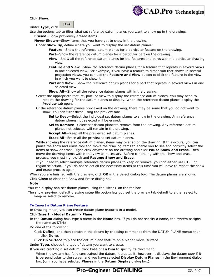
Pro-Engineer DETAILING 88/ 207
Click Show.
Under Type, click . Use the options tab to filter what set reference datum planes you want to show up in the drawing:
Erased—Show previously erased items. Never Shown—Show items that you have yet to show in the drawing. Under Show By, define where you want to display the set datum planes:
Feature—Show the reference datum planes for a particular feature on the drawing. Part—Show the reference datum planes for a particular part on the drawing. View—Show all the reference datum planes for the features and parts within a particular drawing
view. Feature and View—Show the reference datum planes for a feature that repeats in several views
in one selected view. For example, if you have a feature to dimension that shows in several projection views, you can use the Feature and View button to click the feature in the view in which you want to show it.
Part and View—Show the reference datum planes for a part that repeats in several views in one selected view.
Show All—Show all the reference datum planes within the drawing. Select the appropriate feature, part, or view to display the reference datum planes. You may need to
repaint the drawing for the datum planes to display. When the reference datum planes display the Preview tab opens.
Of the reference datum planes previewed on the drawing, there may be some that you do not want to show. You can filter these using the preview tab:
Sel to Keep—Select the individual set datum planes to show in the drawing. Any reference datum planes not selected will be erased.
Sel to Remove—Select set datum planesto remove from the drawing. Any reference datum planes not selected will remain in the drawing.
Accept All—Keep all the previewed set datum planes. Erase All—Erase all the previewed set datum planes.
While showing the reference datum planes, items may overlap on the drawing. If this occurs, you can pause the show and erase tool and move the drawing items to enable you to see and correctly select the items to show or erase. Right-click anywhere on the drawing and click Pause Show and Erase. Then move the drawing items within the view as necessary. Before continuing with the show and erase process, you must right-click and Resume Show and Erase. If you need to select multiple reference datum planes to keep or remove, you can either use CTRL or region selection. If you do not select all the necessary items at this time you will have to repeat the show and erase process again.
When you are finished with the preview, click OK in the Select dialog box. The datum planes are shown. Click Close to close the Show and Erase dialog box. Note:
You can display non-set datum planes using the <icon> on the toolbar. The show_preview_default drawing setup file option lets you set the preview tab default to either select to
keep or select to remove. To Insert a Datum Plane Feature In Drawing mode, you can create datum plane features in a model. Click Insert > Model Datum > Plane. In the Datum dialog box, type a name in the Name box. If you do not specify a name, the system assigns
the name as DTM#. Do one of the following:
Click Define, and then constrain the datum by choosing commands from the DATUM PLANE menu; then click Done.
Click On Surface to place the datum plane feature on a planar model surface. Under Type, choose the type of datum you want to create. If you are creating a set datum, click Free or In Dim to specify its placement.
When the system has fully constrained the datum, it creates it; however, it displays the datum only if it is perpendicular to the screen and you have selected Display Datum Planes in the Environment dialog box (or if you have selected Planes in the Datum Display dialog box).
Pro-Engineer DETAILING 89/ 207
To continue creating datums, click New, type another name in the Name box, and click Define... or On Surface....
To Rename a Model Datum Select the datum you want to rename. Click Edit > Properties. The Datum dialog box opens. Type a new name in the Name box. Click OK to save the name change and to close the dialog box. To Modify the Display of a Set Datum Plane You can lengthen or shorten set datum planes by moving or clipping them. Moving a datum plane moves either side of the datum. Clipping moves the end opposite to the datum name. Select the datum you want to modify. The datum is highlighted and its handles display. Do one of the following:
To move the datum, select anywhere in the drawing window and the datum text moves to a corresponding location along the datum. The name of the datum also flips to the side of the datum where you selected. To clip the datum, select anywhere and the datum plane moves to a corresponding point along the datum. The datum name does not move.
To Create a Draft Datum Plane On the Pro/ENGINEER menu bar, click Insert > Draft Datum > Plane. Click the left mouse button to begin drawing the datum plane. Extend the datum plane to the proper orientation. Place the endpoint by clicking the left mouse button. Type the name for the datum plane. Press Enter. Note: To move or reorient draft datums, select a datum and then click anywhere in the drawing window to relocate or clip it. You can also click Edit > Transform > Rotate or Translate. To Control the Size and Shape of Datum Points To control the size of model datum points and sketched datum points in Drawing mode, use the following drawing setup file options:
Specify a value for the drawing setup file option datum_point_size. To open the drawing setup dialog box, click File > Properties, then Draw Setup on the Menu Manager. The default size is .3125.
To display draft or datum points as a cross, dot, circle, triangle, or square, specify a value for the drawing setup file option datum_point_shape.
Note: These drawing setup file options control the display of points in Drawing mode only. To modify the datum point symbol display for Part or Assembly mode, set the configuration file option datum_point_symbol. To Erase a Set Datum On the Pro/ENGINEER menu bar, click View > Show and Erase. In the Show/Erase dialog box, click Erase. Click the Datum Plane button in the Type box; then select a button in the Erase By box to specify the
feature, view, or part. Select the item to erase. To restore it, click Show, the Datum Plane button in the Type box, and a button in the Show By box to specify the feature, view, or part. Erasing a Set Datum from a Member of an Assembly If a drawing has several occurrences of the same part in an assembly, you can erase a set datum from a particular member of the assembly without causing the selected set datum to disappear from other occurrences of the member. Note: You can erase only set datum planes from the drawing. To remove any other model datum planes (not draft datums) from display uncheck Display Datum Planes in the Environment dialog box, or uncheck Planes from the Datum Display dialog box (View > Display Settings > Datum Display)
. About Working with Model Axes You can manipulate the axes of cylindrical or conical surfaces independently of the Environment dialog box settings. However, keep in mind the following:
The system shows the axis as a line whenever you view it from the side, or as a cross hair whenever you orient the axis normal to the screen. In Drawing mode, if you check Display Datum Axes in the Environment dialog box, axis names appear on the drawing. You can control the axis name display independently of the axis using the Axis Tags check box in the Datum Display dialog box (View > Display Settings > Datum Display).
Pro-Engineer DETAILING 90/ 207
You can create axes in the drawing, however, these axes belong to the drawing, not to the model. A draft axis always appears as a centerline.
By right-clicking a selected axis and using the shortcut menu, you can modify set and unset model axes in the following ways:
Move them to a different location on the drawing sheet. Modify their attachment. Redefine them. Erase and unerase them. To Show Datum Axes on a Drawing When you show datum axes the axes of cylindrical and conical surfaces display on the drawing on the drawing and erases axes that the system shows in a drawing. Because axes are inherited from the model you cannot delete them from within the drawing. Click View > Show and Erase. The Show/Erase dialog box opens. Click Show.
Under Type, click . Use the options tab to filter what set axis you want to show up in the drawing:
Erased—Show previously erased items. Never Shown—Show items that you have yet to show in the drawing. Under Show By, define where you want to display the axes:
Feature—Show the set axes for a particular feature on the drawing. Part—Show the set axes for a particular part on the drawing. View—Show all the set axes for the features and parts within a particular drawing view. Feature and View—Show the set axes for a feature that repeats in several views in one
selected view. For example, if you have a feature to dimension that shows in several projection views, you can use the Feature and View button to click the feature in the view in which you want to show it.
Part and View—Show the set axes for a part that repeats in several views in one selected view. Show All—Show all the set axes within the drawing.
Select the appropriate feature, part, or view to display the reference datum planes. You may need to repaint the drawing for the set axes to display. When the set axes display the Preview tab opens.
Of the set axes previewed on the drawing, there may be some that you do not want to show. You can filter these using the preview tab:
Sel to Keep—Select the individual set axes to show in the drawing. Any set axes not selected will be erased.
Sel to Remove—Select set axes to remove from the drawing. Any set axes not selected will remain in the drawing.
Accept All—Keep all the previewed set axes. Erase All—Erase all the previewed set axes.
While showing the reference datum planes, items may overlap on the drawing. If this occurs, you can pause the show and erase tool and move the drawing items to enable you to see and correctly select the items to show or erase. Right-click anywhere on the drawing and click Pause Show and Erase. Then move the drawing items within the view as necessary. Before continuing with the show and erase process, you must right-click and Resume Show and Erase. If you need to select multiple reference datum planes to keep or remove, you can either use CTRL or region selection. If you do not select all the necessary items at this time you will have to repeat the show and erase process again.
When you are finished with the preview, click OK in the Select dialog box. The set axes are shown. Click Close to close the Show and Erase dialog box. Note:
You can display non-set datum axis using the <icon> on the toolbar. Showing or erasing an axis in a radial pattern affects corresponding axes in all pattern instances. The show_preview_default drawing setup file option lets you set the preview tab default to either select to
keep or select to remove. To Insert a Datum Axis The system displays draft axes in leader style with centerline font. On the Pro/ENGINEER menu bar, click Insert > Model Datum > Axis. In the Axis dialog box, type a name in the Name box.
Pro-Engineer DETAILING 91/ 207
Click Define.... Constrain the datum axis by choosing commands from the DATUM AXIS menu; then choose Done. To continue creating datum axes, click New, type another name in the Name box, and click Define.... To Create a Draft Axis Click Insert > Draft Datum > Axis. Click the left mouse button to start drawing the axis. Move the mouse pointer to extend the axis to the proper orientation (the axis line drags with the mouse).
Place the endpoint by clicking the left mouse button. Type the name of the axis. The system displays the name. To move or reorient the axis, you can move or clip it by selecting the axis and then clicking anywhere in the
drawing window, or choose Rotate or Translate from the Edit > Transform menu. To Rename a Datum Axis Select the datum axis you want to rename, and then right-click and select Properties from the shortcut
menu. In the Axis dialog box, type a new name in the Name box. Click OK to close the dialog box. The axis is renamed. To Create a Set Datum Axis In the drawing window, select the datum axis on the screen, and then right-click and select Properties from
the shortcut menu. In the Axis dialog box, click -A- (set). The system encloses the axis in a feature control frame. Click OK to close the Axis dialog box. To Specify the Placement of a Set Datum Axis In the drawing window, select the axis you want to place or relocate, and then right-click and select
Properties from the shortcut menu. Click In Dim and then Pick Dim in the Axis dialog box. Select a dimension in the model. The system places the set axis under the dimension on the screen. Click OK to close the dialog box and save the change. Note: If you set the drawing setup file option gtol_datums to STD_ASME or STD_ISO, you can also place a set datum axis on a geometric tolerance. Click In Gtol and Pick Gtol...; then select a gtol in the model. Axis Display Options By setting the drawing setup file option axis_interior_clipping to no, you can set the axis display according to these three ANSI Y14.2M standard requirements:
Line starts and ends with a dash. Perpendicular axes of a centerline intersect at a short dash. Very short centerlines are unbroken. Axes that are set to CTRLFONT actually are shown as CTRLFONT_S_L or CTRLFONT_L_L, depending on their orientation. You can control them by setting line_style_length to CTRLFONT_S_L or CTRLFONT_L_L, not CTRLFONT. To control axes that are perpendicular to the view, set line_style_length to CTRLFONT_S_L; to control axes that are parallel to the view, set it to CTRLFONT_L_L. This option affects the axis display in the following ways:
Axes parallel to the screen appear in one line in a centerline font, beginning and ending with a long dash. Axes perpendicular to the screen appear in two lines, each of them drawn in two segments. Perpendicular lines intersect at a short dash. When any axis is too short, it appears in a solid line font. Using the drawing setup file option radial_pattern_axis_circle, you can set the display mode for axes of rotation that are perpendicular to the screen in radial pattern features. When you set the option to yes, a circular shared axis appears, and the axis lines pass through the center of a rotational pattern. However, this only affects patterns that you create using the Dim Pattern command. The following restrictions apply when you set this drawing setup file option to yes:
You cannot move, clip, or modify the line style of a circular shared axis that appears once you choose the Show command button from the Show/Erase dialog box (accessed by clicking View > Show and Erase on the menu bar).
In a clipped view, the system only displays portions of lines and circles that are inside a view boundary. You cannot use radial patterns of group features. You cannot show radial pattern axis circles for reference patterns. To Modify the Line Style of a Model or Draft Axis On the Pro/ENGINEER menu bar, click Format > Line Styles. The LINE STYLES menu opens in the Menu
Manager.
Pro-Engineer DETAILING 92/ 207
Select the axis name or the axis itself (for model axis features). The Line Style dialog box opens. In the Line Style dialog box, select a line style from the Style list. Click Apply. The axis acquires the specified line style. To reset it to the old style, click Reset and Apply.
Note: When you set the drawing setup file option axis_interior_clipping to no, you can still change the axis line style. However, this disables the automatic adjustment of a pattern.
To Create a Break in a Model Axis Line In the Graphics window, select the axis line in which you want to create the break. On the Pro/ENGINEER menu bar, click Insert > Break. The BREAK menu opens in the Menu Manager. Add
is the default selection. Select the first location on the axis line to begin the break. Select the second location to finish the break. The system creates the break. To Delete a Portion of a Normal-to-Screen Axis Select an axis line, and then click Edit > Delete. To resume the display of all portions of the axis, click View > Show and Erase The Show and Erase dialog
box opens. Click Axis in the Type box. Click Show All. The deleted axis lines are redisplayed and highlighted in a different color. If Preview is
selected in the dialog box, click Accept All. All axis lines are restored to the display. Note: If you choose the normal-to-screen axis, the system erases all of the lines for that axis.
To Create an Axis Symmetry Line Using the following procedure, you can create an extension between axis cross hairs showing that the axes are symmetrical about a dimension. On the menu bar, click Insert > Symmetry Line Axis. Select two axes that are perpendicular (normal) to the plane of the screen (shown as cross hairs). To extend
the symmetry line to either side, grab a handle of the axis with the mouse pointer and click anywhere outside of the line.
Example: Axis Symmetry Lines
1. Axis symmetry line. About Rotating Axes Using the Edit > Attachment command you can rotate model axes that are normal to the screen. When you rotate the axis, it rotates according to another reference entity that you select, such as an edge or point, as shown in the following diagram. The rotated axis remains normal (perpendicular) to the screen; however, the cross reorients according to your specifications. Rotating Axes
The Rotate Axis menu displays the following options:
Through Geom—Picks an edge, datum point, or center of an axis normal to the screen through which the axis line that is closest to that point passes.
Pick Point—Picks a point on the screen through which the axis line passes. Parallel—Picks a linear edge or datum curve to which the axis line is parallel. Horizontal—Returns the axis to its standard orientation. Enter Angle—Specifies an angle for axis rotation about the X-axis. To Rotate an Axis Select the axis you want to rotate, and then right-click on the axis to display the shortcut menu. Click Edit Attachment in the shortcut menu. Select another axis center or edge as a rotation reference to orient the selected axis, and then press ENTER.
The axis rotates in reference to the edge or second axis reference. To Show 3D Symbols in Drawings Click View > Show and Erase. The Show/Erase dialog box opens. Click Show.
Under Type, click .
Pro-Engineer DETAILING 93/ 207
Use the options tab to filter what symbols you want to show up in the drawing: Erased—Show previously erased items. Never Shown—Show items that you have yet to show in the drawing. Under Show By, define where you want to display the symbols:
Feature—Show the symbols for a particular feature on the drawing. Part—Show the symbols for a particular part on the drawing. View—Show all the symbols for the features and parts within a particular drawing view. Feature and View—Show the symbols for a feature that repeats in several views in one selected view. For
example, if you have a feature to dimension that shows in several projection views, you can use the Feature and View button to click the feature in the view in which you want to show it.
Part and View—Show the symbols for a part that repeats in several views in one selected view. Show All—Show all the symbols within the drawing. Select the appropriate feature, part, or view to display the symbols. You may need to repaint the drawing for
the set axes to display. When the dimensions display the Preview tab opens. Of the symbols previewed on the drawing, there may be some that you do not want to show. You can filter these using the preview tab:
Sel to Keep—Select the individual symbols to show in the drawing. Any dimensions not selected will be erased. Sel to Remove—Select symbols to remove from the drawing. Any dimensions not selected will remain in the drawing. Accept All—Keep all the previewed symbols. Erase All—Erase all the previewed symbols. While showing the symbols, items may overlap on the drawing. If this occurs, you can pause the show and erase tool and move the drawing items to enable you to see and correctly select the items to show or erase. Right-click anywhere on the drawing and click Pause Show and Erase. Then move the drawing items within the view as necessary. Before continuing with the show and erase process, you must right-click and Resume Show and Erase. If you need to select multiple reference datum planes to keep or remove, you can either use CTRL or region selection. If you do not select all the necessary items at this time you will have to repeat the show and erase process again.
When you are finished with the preview, click OK in the Select dialog box. The symbols are shown. Click Close to close the Show and Erase dialog box. Note: The show_preview_default drawing setup file option lets you set the preview tab default to either select to keep or select to remove. To Insert a Symbol from the Symbol Palette The symbol palette is a .dwg file dedicated to storing frequently used symbol instances. These symbols are usually simple symbols, without graphic groups or variable text. Click Insert > Drawing Symbol > From Palette. The Symbol Instance Palette opens. Commonly used
symbols are arranged in two sections. The left section stores the symbols as free-placement types. The right section shows the same symbols as On-Entity placement types.
Place the desired symbol, in one of the following ways: To place a free-placement symbol,
Click the symbol you want to place. The symbol is highlighted. Move the cursor off of the palette and onto the drawing. The symbol is attached to the cursor. Drag the cursor to the symbol location and left click to place it. The symbol is placed, and the instance
remains on the cursor to let you place another one. To cancel placement, click the right mouse button.
To place an On Entity symbol, Select the symbol to place. The symbol is highlighted, but it is not attached to the cursor. Click to select the attachment object in the drawing. The symbol is added, and you may continue to
select attachment points for more symbols. Click OK in the Select dialog box to stop placing symbols.
To Insert a Custom Symbol Use custom symbols placement to add instances of generic symbols, for example symbols with grouped graphics or variable text.
Click Insert > Drawing Symbol > Custom. The Custom Drawing Symbol dialog box opens. Click the name of the symbol to place in the Symbol Name list box. The list box shows all symbols present in the drawings Symbol Gallery. If the symbol you want has not been added to the drawing yet,
Pro-Engineer DETAILING 94/ 207
use the Browse button to find its .sym file in the symbol library, or use the New button to create a new symbol definition. Optionally, use the General tab to choose the placement properties size and height for the instance Use the Grouping tab to specify which groups will show in the instance. Use the Variable Text tab to select the content of notes appearing with the symbol.
Move the cursor onto the sheet. The symbol is attached to the cursor. To place a free-placement symbol,
Drag the cursor to the symbol location and left click to place it. The symbol is placed, and the instance remains on the cursor to let you place another one. To cancel placement, click the right mouse button.
To place an On Entity symbol, Click to select the attachment object in the drawing. The symbol is added, and you may continue to select attachment points for more symbols. Click OK in the Select dialog box to stop placing symbols.
To place a With Leader symbol, Click to select the attachment object in the drawing. When the leader is added, middle click to place the instance. Click OK in the Select dialog box to stop placing symbols.
To Show Surface Finish Symbols Click View > Show and Erase. The Show/Erase dialog box opens. Click Show.
Under Type, click . Use the options tab to filter what surface finish symbols you want to show up in the drawing:
Erased—Show previously erased items. Never Shown—Show items that you have yet to show in the drawing. Under Show By, define where you want to display the surface finish symbols:
Feature—Show the surface finish symbols for a particular feature on the drawing. Part—Show the surface finish symbols for a particular part on the drawing. View—Show all the surface finish symbols for the features and parts within a particular drawing
view. Feature and View—Show the surface finish symbols for a feature that repeats in several views
in one selected view. For example, if you have a feature to dimension that shows in several projection views, you can use the Feature and View button to click the feature in the view in which you want to show it.
Part and View—Show the surface finish symbols for a part that repeats in several views in one selected view.
Show All—Show all the surface finish symbols within the drawing. Select the appropriate feature, part, or view to display the reference datum planes. You may need to
repaint the drawing for the datum planes to display. When the dimensions display the Preview tab opens.
Of the surface finish symbols previewed on the drawing, there may be some that you do not want to show. You can filter these using the preview tab:
Sel to Keep—Select the individual surface finish symbols to show in the drawing. Any surface finish symbols not selected will be erased.
Sel to Remove—Select surface finish symbols to remove from the drawing. Any surface finish symbols not selected will remain in the drawing.
Accept All—Keep all the previewed surface finish symbols. Erase All—Erase all the previewed surface finish symbols.
While showing the surface finish symbols, items may overlap on the drawing. If this occurs, you can pause the show and erase tool and move the drawing items to enable you to see and correctly select the items to show or erase. Right-click anywhere on the drawing and click Pause Show and Erase. Then move the drawing items within the view as necessary. Before continuing with the show and erase process, you must right-click and Resume Show and Erase. If you need to select multiple reference datum planes to keep or remove, you can either use CTRL or region selection. If you do not select all the necessary items at this time you will have to repeat the show and erase process again.
When you are finished with the preview, click OK in the Select dialog box. The datum planes are shown.
Pro-Engineer DETAILING 95/ 207
Click Close to close the Show and Erase dialog box. Note: The show_preview_default drawing setup file option lets you set the preview tab default to either select to keep or select to remove. To Insert Surface Finish Symbols Click Insert > Surface Finish. The menu manager opens. Using the GET SYMBOL menu, do one of the following:
Use Name to select a symbol from the namelist menu. This menu lists all of the symbols that are currently in the drawing. When symbols appear to have the same names, but are, in fact, from different symbol directories, the system identifies them in the SYMBOL NAMES menu with a number in parentheses (#). The one-line help for each name provides the name and path for each symbol.
Use Pick Inst to select a symbol by selecting any instance of the symbol in the drawing. Use Retrieve to select a symbol by choosing one from a list of symbols on disk. Selecting UP brings you up
one directory. Selecting another directory name brings you down to that directory. The menu name is the name of the current directory. Unlike storing a symbol, you can retrieve one from anywhere you have read permission, both up and down the directory tree.
Click one of the commands from the INST ATTACH menu. Respond to the system prompts and menu commands for the commands you chose. Type a value for the surface roughness. The system places the symbol on each surface you select on the
drawing with the size relative to the default text height. About Defining Symbols Use the Redefine command in the Format > Symbol Gallery menu to add, move, delete, or change detail items composing a symbol. You can modify a symbol by doing the following:
Create new entities composing a generic symbol. Modify existing entities composing a generic symbol. Change the attachment style. Change group definition by adding or removing entities from groups, or deleting one or all groups. Effect of Symbol Redefinition on Instances When you redefine a symbol, it affects the display of all subsequent instances and all symbol instances that you have added to a drawing using the By Reference command. About the System Symbols Area The symbols directory contains libraries of Pro/ENGINEER symbols that are available with the Pro/DETAIL module. This area is usually read-only. The Welding Symbols Library, for example, provides a collection of generic system symbols according to the ANSI standard, and a collection of symbols according to the ISO standard. Using this library, you can create a variety of welding, brazing, and examination symbols in a drawing. Before you create an instance, familiarize yourself with the procedure for adding custom instances. To Set the User-Defined Symbols Area Pro/ENGINEER is set up to store and access symbols in two different areas:
user-defined symbols area is the default storage area for special or user-created symbols. system symbols area is usually designated as read-only and contains standard symbols provided with the
Pro/DETAIL module, such as the Welding Symbols Library. To specify the directory in which you want to store user-defined symbols, set the configuration file option pro_symbol_dir. This automatically creates a search path to the specified directory. Pro/ENGINEER saves all symbols into and retrieves them from this directory by default if you add this option to your configuration file. If you change the location, the system does not delete symbols used in the drawing; once you add them, it stores the definitions locally in the drawing. You should establish a single directory as your user library for all standard symbols. If you do not specify one, the system searches in the current working directory. You can change the default area for user-defined symbols by entering a new value for the pro_symbol_dir configuration file option. When you change this directory, you do not have to modify the configuration file; however, this change is valid only for the current Pro/ENGINEER session. Use this option to define new symbols that you store in a local or temporary directory; you can still easily retrieve symbols from the standard symbols area. To Change the Symbol Directory The symbol directory is determined by the configuration option pro_symbol_dir. Click Format > Symbol Gallery. The SYM Gallery menu appears on the Menu Manager. Click Symbol Dir. Type the pathname of the directory for the new pro_symbol_dir. To restore the default pathname in the current session, do one of the following:
Pro-Engineer DETAILING 96/ 207
Repeat this process and substitute the original pathname. Click Utilities > Options from the Pro/ENGINEER menu bar and reload the configuration file in which this
option resides. To Store a Symbol You do not have to save a symbol in order to continue using it in the drawing. However, to make symbols available for use in other drawings, you must save them to disk as .sym files. You can save any symbol in the drawing as an individual .sym file. Click Format > Symbol Gallery. The SYMBOL menu appears. Click Write. Specify the symbol by choosing Name or Pick Inst from the GET SYMBOL menu. Type the offset directory path from the directory specified by pro_symbol_dir in which to store the symbol. About Symbol Types While you can use either standard supplied symbols, or customize your own, the drawing symbols are characterized in the following manner:
Simple: Each instance, or placement, of the symbol is identical. The graphic and textual content remain unchanged.
Generic: Each instance contains familiar geometry or textual content, yet variations can exist. The graphic and textual content are chosen from a common group of symbol attributes.
Surface Finish: Generic surface finish symbol that consists of building blocks, or groups
Weld: About Simple Symbols To define a simple symbol, you must draw the symbol geometry, then specify attributes, origin or attachment point, and any variable text notes needed. A simple symbol does not include grouped geometry, as does a generic symbol. To Define a Simple Symbol
Create the draft geometry and add notes to include as fixed or variable text in the symbol. The text size and placement should be proportional to the geometry. Symbol text and geometry remain proportional when you modify the symbol height. Click Format > Symbol Gallery. The SYM Gallery menu appears. Click Define. Type a name for the symbol and press Enter. The symbol edit window appears. Use the drafting tools to define the symbol shape or click Copy Drawing to copy entities from the format or drawing into the symbol edit window. Click Done when finished. The Symbol Definition Attributes dialog box opens. Select the desired attributes from the Symbol Definition Attributes dialog box; then click OK. Using the Symbol Definition Attributes dialog box, you can specify the following symbol attributes:
Placement type Free, on an entity, or normal to an entity Left, right, or radial leader
Symbol instance height Fixed Variable in drawing units, model units, or text-related
Position and other characteristics At a fixed text angle With an elbow Mirror image of the original geometry or text
Variable text If you insert text notes with a backslash before and after them ( \notetext\ ) in the symbol definition, these notes become "variable text" notes. They appear in the Var Text tab of the Symbol Definition Attributes dialog box. Variable text means that you may enter a selection of values in the preset values text box for each variable text note. For example, if your note had the text "Drafter Name \names\," "names" would appear in the Var Text tab. You could enter a list of employees names in the pre set values area to select from when the instance is placed. When you place the instance, you can select a name to follow "Drafter Name" from a drop down list in the Custom Drawing Symbol dialog box. (Select the symbol and click Properties on the right mouse button shortcut menu to show the dialog box.)
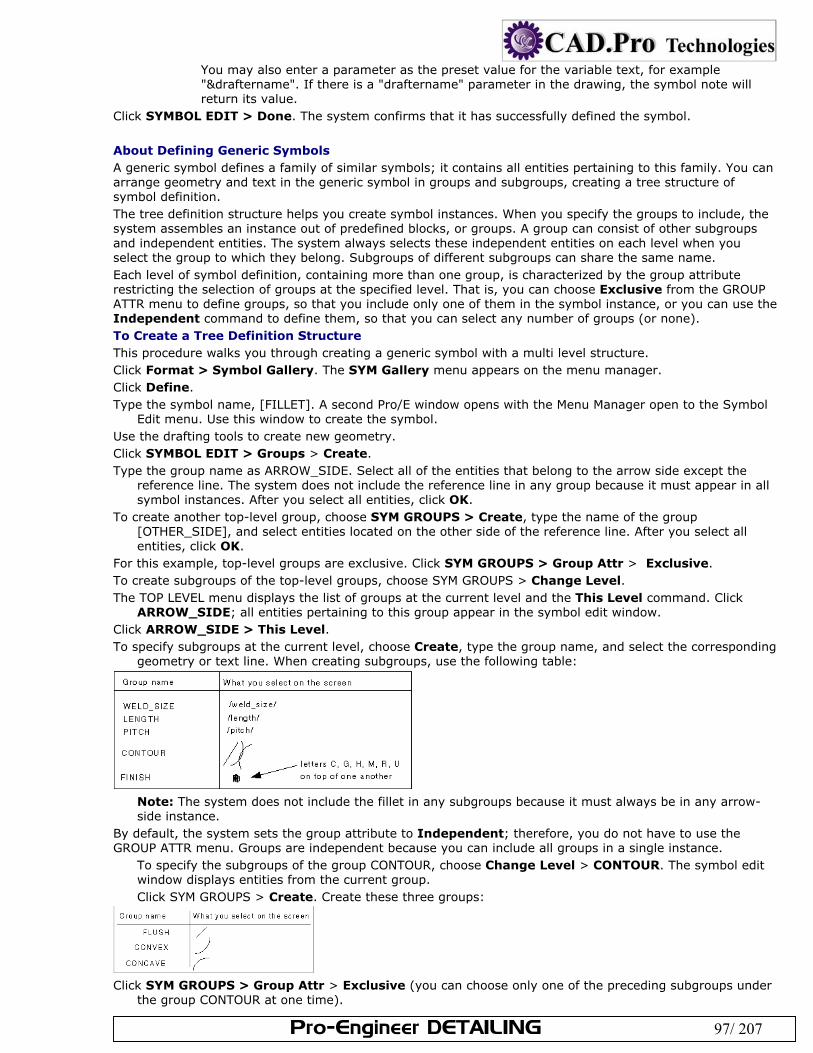
Pro-Engineer DETAILING 97/ 207
You may also enter a parameter as the preset value for the variable text, for example "&draftername". If there is a "draftername" parameter in the drawing, the symbol note will return its value.
Click SYMBOL EDIT > Done. The system confirms that it has successfully defined the symbol. About Defining Generic Symbols A generic symbol defines a family of similar symbols; it contains all entities pertaining to this family. You can arrange geometry and text in the generic symbol in groups and subgroups, creating a tree structure of symbol definition. The tree definition structure helps you create symbol instances. When you specify the groups to include, the system assembles an instance out of predefined blocks, or groups. A group can consist of other subgroups and independent entities. The system always selects these independent entities on each level when you select the group to which they belong. Subgroups of different subgroups can share the same name. Each level of symbol definition, containing more than one group, is characterized by the group attribute restricting the selection of groups at the specified level. That is, you can choose Exclusive from the GROUP ATTR menu to define groups, so that you include only one of them in the symbol instance, or you can use the Independent command to define them, so that you can select any number of groups (or none). To Create a Tree Definition Structure This procedure walks you through creating a generic symbol with a multi level structure. Click Format > Symbol Gallery. The SYM Gallery menu appears on the menu manager. Click Define. Type the symbol name, [FILLET]. A second Pro/E window opens with the Menu Manager open to the Symbol
Edit menu. Use this window to create the symbol. Use the drafting tools to create new geometry. Click SYMBOL EDIT > Groups > Create. Type the group name as ARROW_SIDE. Select all of the entities that belong to the arrow side except the
reference line. The system does not include the reference line in any group because it must appear in all symbol instances. After you select all entities, click OK.
To create another top-level group, choose SYM GROUPS > Create, type the name of the group [OTHER_SIDE], and select entities located on the other side of the reference line. After you select all entities, click OK.
For this example, top-level groups are exclusive. Click SYM GROUPS > Group Attr > Exclusive. To create subgroups of the top-level groups, choose SYM GROUPS > Change Level. The TOP LEVEL menu displays the list of groups at the current level and the This Level command. Click
ARROW_SIDE; all entities pertaining to this group appear in the symbol edit window. Click ARROW_SIDE > This Level. To specify subgroups at the current level, choose Create, type the group name, and select the corresponding
geometry or text line. When creating subgroups, use the following table:
Note: The system does not include the fillet in any subgroups because it must always be in any arrow-side instance.
By default, the system sets the group attribute to Independent; therefore, you do not have to use the GROUP ATTR menu. Groups are independent because you can include all groups in a single instance.
To specify the subgroups of the group CONTOUR, choose Change Level > CONTOUR. The symbol edit window displays entities from the current group. Click SYM GROUPS > Create. Create these three groups:
Click SYM GROUPS > Group Attr > Exclusive (you can choose only one of the preceding subgroups under
the group CONTOUR at one time).
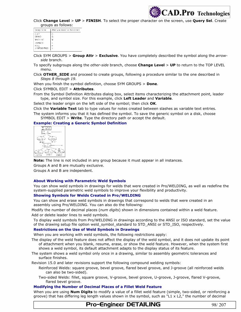
Pro-Engineer DETAILING 98/ 207
Click Change Level > UP > FINISH. To select the proper character on the screen, use Query Sel. Create groups as follows:
Click SYM GROUPS > Group Attr > Exclusive. You have completely described the symbol along the arrow-
side branch. To specify subgroups along the other-side branch, choose Change Level > UP to return to the TOP LEVEL
menu. Click OTHER_SIDE and proceed to create groups, following a procedure similar to the one described in
Steps 8 through 19. When you finish the symbol definition, choose SYM GROUPS > Done. Click SYMBOL EDIT > Attributes. From the Symbol Definition Attributes dialog box, select items characterizing the attachment point, leader
type, and symbol size. For this example, click Left Leader and Variable. Select the leader origin on the left side of the symbol; then click OK. Click the Variable Text tab to type values for notes created between slashes as variable text entries. The system informs you that it has defined the symbol. To save the generic symbol on a disk, choose
SYMBOL EDIT > Write. Type the directory path or accept the default. Example: Creating a Generic Symbol Definition
Note: The line is not included in any group because it must appear in all instances. Groups A and B are mutually exclusive. Groups A and B are independent.
About Working with Parametric Weld Symbols You can show weld symbols in drawings for welds that were created in Pro/WELDING, as well as redefine the system-supplied parametric weld symbols to improve your flexibility and productivity. Showing Symbols for Welds Created in Pro/WELDING You can show and erase weld symbols in drawings that correspond to welds that were created in an assembly using Pro/WELDING. You can also do the following:
Modify the number of decimal places (num digits) shown in dimensions contained within a weld feature. Add or delete leader lines to weld symbols. To display weld symbols from Pro/WELDING in drawings according to the ANSI or ISO standard, set the value of the drawing setup file option weld_symbol_standard to STD_ANSI or STD_ISO, respectively. Restrictions on the Use of Weld Symbols in Drawings When you are working with weld symbols, the following restrictions apply:
The display of the weld feature does not affect the display of the weld symbol, and it does not update its point of attachment when you blank, resume, erase, or show the weld feature. However, when the system first shows a weld symbol, its default attachment adapts to the display status of its feature.
The system shows a weld symbol only once in a drawing, similar to assembly geometric tolerances and surface finishes.
Revision 15.0 and later revisions support the following compound welding symbols: Reinforced Welds: square groove, bevel groove, flared bevel groove, and J-groove (all reinforced welds
can also be two-sided). Two-sided Welds: fillet, square groove, V-groove, bevel groove, U-groove, J-groove, flared V-groove,
flared bevel groove. Modifying the Number of Decimal Places of a Fillet Weld Feature When you are using Num Digits to modify a value of a fillet weld feature (simple, two-sided, or reinforcing a groove) that has differing leg length values shown in the symbol, such as "L1 x L2," the number of decimal
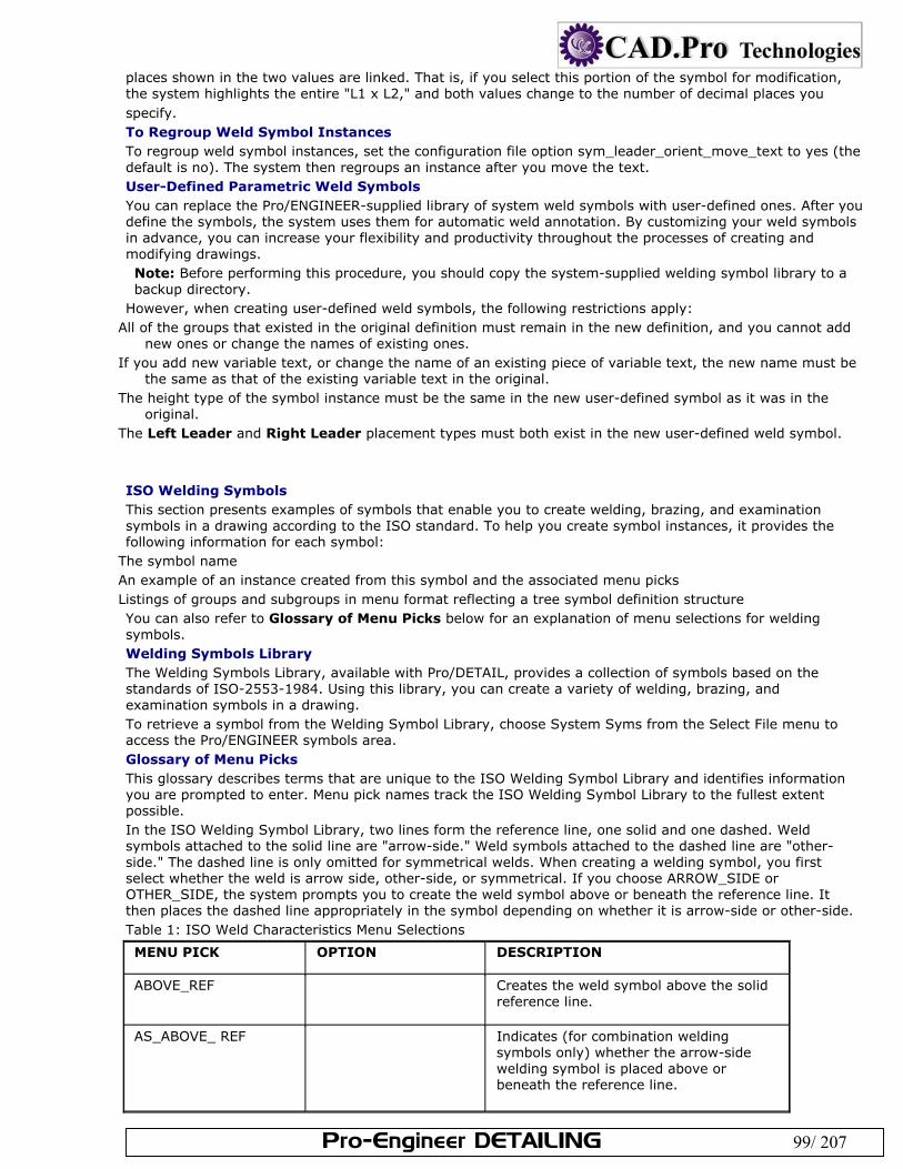
Pro-Engineer DETAILING 99/ 207
places shown in the two values are linked. That is, if you select this portion of the symbol for modification, the system highlights the entire "L1 x L2," and both values change to the number of decimal places you specify. To Regroup Weld Symbol Instances To regroup weld symbol instances, set the configuration file option sym_leader_orient_move_text to yes (the default is no). The system then regroups an instance after you move the text. User-Defined Parametric Weld Symbols You can replace the Pro/ENGINEER-supplied library of system weld symbols with user-defined ones. After you define the symbols, the system uses them for automatic weld annotation. By customizing your weld symbols in advance, you can increase your flexibility and productivity throughout the processes of creating and modifying drawings. Note: Before performing this procedure, you should copy the system-supplied welding symbol library to a backup directory.
However, when creating user-defined weld symbols, the following restrictions apply: All of the groups that existed in the original definition must remain in the new definition, and you cannot add
new ones or change the names of existing ones. If you add new variable text, or change the name of an existing piece of variable text, the new name must be
the same as that of the existing variable text in the original. The height type of the symbol instance must be the same in the new user-defined symbol as it was in the
original. The Left Leader and Right Leader placement types must both exist in the new user-defined weld symbol. ISO Welding Symbols This section presents examples of symbols that enable you to create welding, brazing, and examination symbols in a drawing according to the ISO standard. To help you create symbol instances, it provides the following information for each symbol:
The symbol name An example of an instance created from this symbol and the associated menu picks Listings of groups and subgroups in menu format reflecting a tree symbol definition structure You can also refer to Glossary of Menu Picks below for an explanation of menu selections for welding symbols. Welding Symbols Library The Welding Symbols Library, available with Pro/DETAIL, provides a collection of symbols based on the standards of ISO-2553-1984. Using this library, you can create a variety of welding, brazing, and examination symbols in a drawing. To retrieve a symbol from the Welding Symbol Library, choose System Syms from the Select File menu to access the Pro/ENGINEER symbols area. Glossary of Menu Picks This glossary describes terms that are unique to the ISO Welding Symbol Library and identifies information you are prompted to enter. Menu pick names track the ISO Welding Symbol Library to the fullest extent possible. In the ISO Welding Symbol Library, two lines form the reference line, one solid and one dashed. Weld symbols attached to the solid line are "arrow-side." Weld symbols attached to the dashed line are "other-side." The dashed line is only omitted for symmetrical welds. When creating a welding symbol, you first select whether the weld is arrow side, other-side, or symmetrical. If you choose ARROW_SIDE or OTHER_SIDE, the system prompts you to create the weld symbol above or beneath the reference line. It then places the dashed line appropriately in the symbol depending on whether it is arrow-side or other-side. Table 1: ISO Weld Characteristics Menu Selections
MENU PICK OPTION DESCRIPTION
ABOVE_REF Creates the weld symbol above the solid reference line.
AS_ABOVE_ REF Indicates (for combination welding symbols only) whether the arrow-side welding symbol is placed above or beneath the reference line.
Pro-Engineer DETAILING 100/ 207
BENEATH_REF Creates the weld symbol beneath the solid reference line.
BUTT_SIZE Refers to the final size of the weld, depending on the symbol type (arrow-side, other-side, symmetrical, or staggered). It might have the suffix "AS" (arrow-side) or "OS" (other-side) to indicate the appropriate weld side.
CONTOUR SMOOTH_BLEND Describes the final shape of the weld. This choice indicates that the toes of the weld are blended smoothly.
FINISH In the ANSI standard, this specifies the method of finishing. In the ISO standard, the system adds a machine finish surface texture symbol above the contour symbol.
FILLET_SIZE Refers to the final size of the weld, depending on the symbol type (arrow-side, other-side, symmetrical, or staggered). It might have the suffix "AS" (arrow-side) or "OS" (other-side) to indicate the appropriate weld side.
FIL_SIZE Refers to the final size of the weld, depending on the symbol type (arrow-side, other-side, symmetrical, or staggered). It might have the suffix "AS" (arrow-side) or "OS" (other-side) to indicate the appropriate weld side.
HOLE_DIA Refers to the diameter of a plug weld.
OS_ABOVE_ REF Indicates (for combination welding symbols only) whether the other-side welding symbol is placed above or beneath the reference line.
PROJECT_DIA Refers to the diameter of a projection weld.
SEAM_WIDTH Refers to the width of a seam weld.
SPOT_DIA Refers to the diameter of a spot or fusion weld.
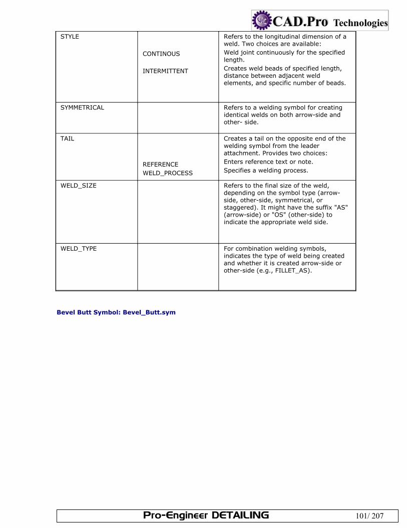
Pro-Engineer DETAILING 101/ 207
STYLE CONTINOUS INTERMITTENT
Refers to the longitudinal dimension of a weld. Two choices are available: Weld joint continuously for the specified length. Creates weld beads of specified length, distance between adjacent weld elements, and specific number of beads.
SYMMETRICAL
Refers to a welding symbol for creating identical welds on both arrow-side and other- side.
TAIL REFERENCE WELD_PROCESS
Creates a tail on the opposite end of the welding symbol from the leader attachment. Provides two choices: Enters reference text or note. Specifies a welding process.
WELD_SIZE Refers to the final size of the weld, depending on the symbol type (arrow-side, other-side, symmetrical, or staggered). It might have the suffix "AS" (arrow-side) or "OS" (other-side) to indicate the appropriate weld side.
WELD_TYPE For combination welding symbols, indicates the type of weld being created and whether it is created arrow-side or other-side (e.g., FILLET_AS).
Bevel Butt Symbol: Bevel_Butt.sym
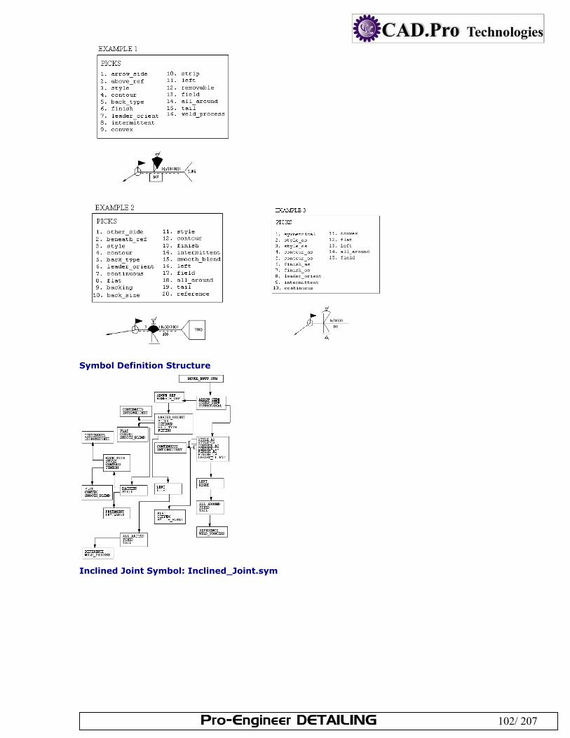
Pro-Engineer DETAILING 102/ 207
Symbol Definition Structure
Inclined Joint Symbol: Inclined_Joint.sym
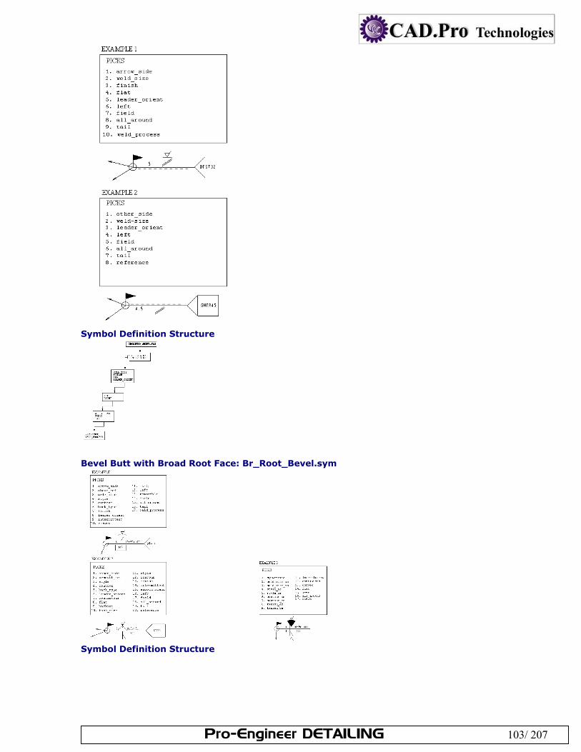
Pro-Engineer DETAILING 103/ 207
Symbol Definition Structure
Bevel Butt with Broad Root Face: Br_Root_Bevel.sym
Symbol Definition Structure
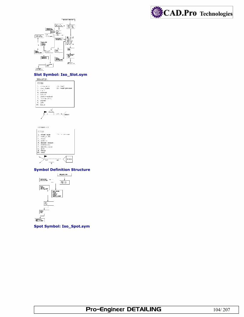
Pro-Engineer DETAILING 104/ 207
Slot Symbol: Iso_Slot.sym
Symbol Definition Structure
Spot Symbol: Iso_Spot.sym
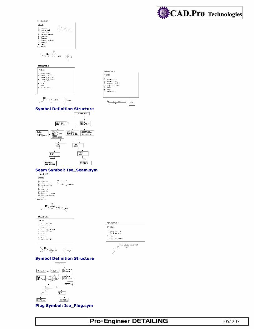
Pro-Engineer DETAILING 105/ 207
Symbol Definition Structure
Seam Symbol: Iso_Seam.sym
Symbol Definition Structure
Plug Symbol: Iso_Plug.sym
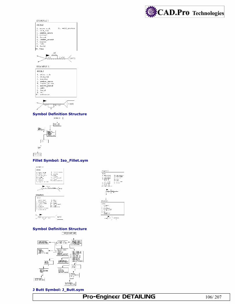
Pro-Engineer DETAILING 106/ 207
Symbol Definition Structure
Fillet Symbol: Iso_Fillet.sym
Symbol Definition Structure
J Butt Symbol: J_Butt.sym
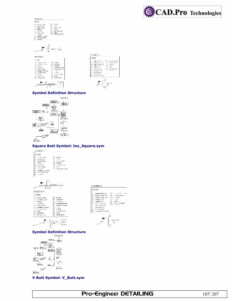
Pro-Engineer DETAILING 107/ 207
Symbol Definition Structure
Square Butt Symbol: Iso_Square.sym
Symbol Definition Structure
V Butt Symbol: V_Butt.sym
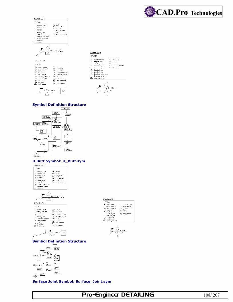
Pro-Engineer DETAILING 108/ 207
Symbol Definition Structure
U Butt Symbol: U_Butt.sym
Symbol Definition Structure
Surface Joint Symbol: Surface_Joint.sym
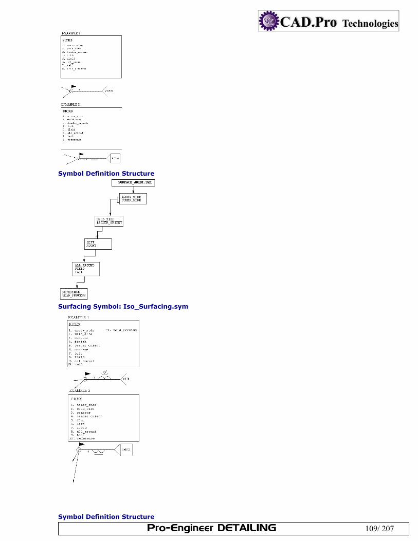
Pro-Engineer DETAILING 109/ 207
Symbol Definition Structure
Surfacing Symbol: Iso_Surfacing.sym
Symbol Definition Structure
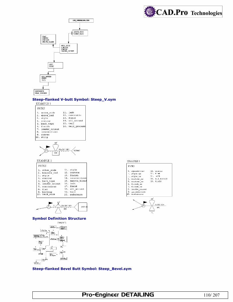
Pro-Engineer DETAILING 110/ 207
Steep-flanked V-butt Symbol: Steep_V.sym
Symbol Definition Structure
Steep-flanked Bevel Butt Symbol: Steep_Bevel.sym
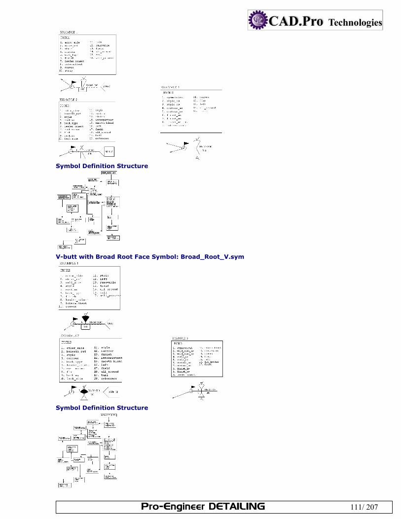
Pro-Engineer DETAILING 111/ 207
Symbol Definition Structure
V-butt with Broad Root Face Symbol: Broad_Root_V.sym
Symbol Definition Structure
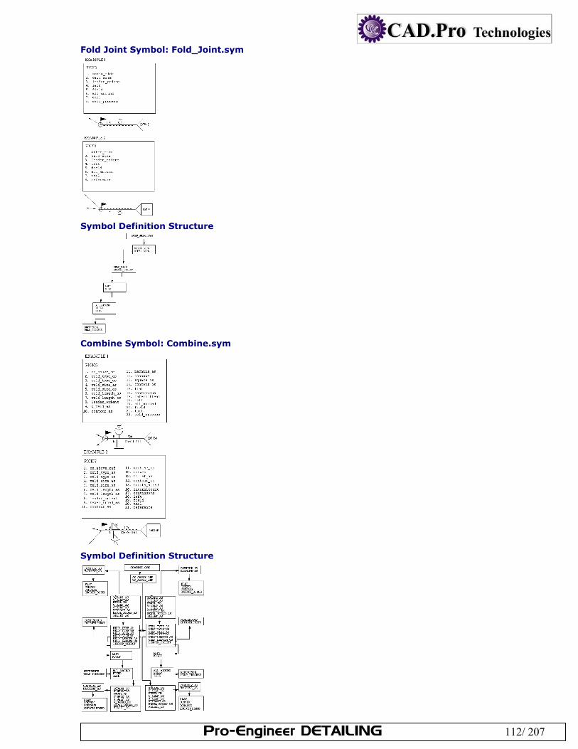
Pro-Engineer DETAILING 112/ 207
Fold Joint Symbol: Fold_Joint.sym
Symbol Definition Structure
Combine Symbol: Combine.sym
Symbol Definition Structure
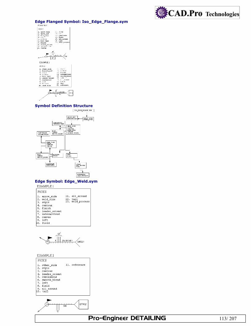
Pro-Engineer DETAILING 113/ 207
Edge Flanged Symbol: Iso_Edge_Flange.sym
Symbol Definition Structure
Edge Symbol: Edge_Weld.sym
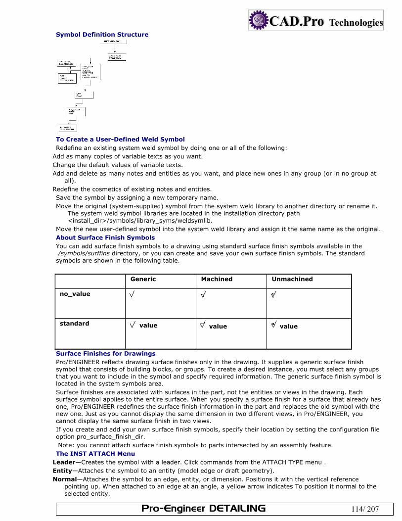
Pro-Engineer DETAILING 114/ 207
Symbol Definition Structure
To Create a User-Defined Weld Symbol Redefine an existing system weld symbol by doing one or all of the following:
Add as many copies of variable texts as you want. Change the default values of variable texts. Add and delete as many notes and entities as you want, and place new ones in any group (or in no group at
all). Redefine the cosmetics of existing notes and entities. Save the symbol by assigning a new temporary name. Move the original (system-supplied) symbol from the system weld library to another directory or rename it.
The system weld symbol libraries are located in the installation directory path <install_dir>/symbols/library_syms/weldsymlib.
Move the new user-defined symbol into the system weld library and assign it the same name as the original. About Surface Finish Symbols You can add surface finish symbols to a drawing using standard surface finish symbols available in the /symbols/surffins directory, or you can create and save your own surface finish symbols. The standard symbols are shown in the following table.
Generic Machined Unmachined
no_value
standard value value value
Surface Finishes for Drawings Pro/ENGINEER reflects drawing surface finishes only in the drawing. It supplies a generic surface finish symbol that consists of building blocks, or groups. To create a desired instance, you must select any groups that you want to include in the symbol and specify required information. The generic surface finish symbol is located in the system symbols area. Surface finishes are associated with surfaces in the part, not the entities or views in the drawing. Each surface symbol applies to the entire surface. When you specify a surface finish for a surface that already has one, Pro/ENGINEER redefines the surface finish information in the part and replaces the old symbol with the new one. Just as you cannot display the same dimension in two different views, in Pro/ENGINEER, you cannot display the same surface finish in two views. If you create and add your own surface finish symbols, specify their location by setting the configuration file option pro_surface_finish_dir. Note: you cannot attach surface finish symbols to parts intersected by an assembly feature. The INST ATTACH Menu
Leader—Creates the symbol with a leader. Click commands from the ATTACH TYPE menu . Entity—Attaches the symbol to an entity (model edge or draft geometry). Normal—Attaches the symbol to an edge, entity, or dimension. Positions it with the vertical reference
pointing up. When attached to an edge at an angle, a yellow arrow indicates To position it normal to the selected entity.
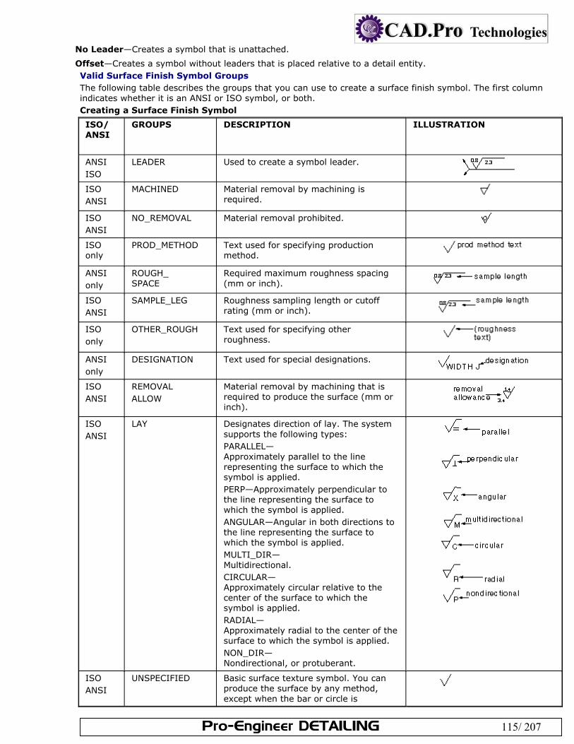
Pro-Engineer DETAILING 115/ 207
No Leader—Creates a symbol that is unattached.
Offset—Creates a symbol without leaders that is placed relative to a detail entity. Valid Surface Finish Symbol Groups The following table describes the groups that you can use to create a surface finish symbol. The first column indicates whether it is an ANSI or ISO symbol, or both. Creating a Surface Finish Symbol
ISO/ ANSI
GROUPS DESCRIPTION ILLUSTRATION
ANSI ISO
LEADER Used to create a symbol leader.
ISO ANSI
MACHINED Material removal by machining is required.
ISO ANSI
NO_REMOVAL Material removal prohibited.
ISO only
PROD_METHOD Text used for specifying production method.
ANSI only
ROUGH_ SPACE
Required maximum roughness spacing (mm or inch).
ISO ANSI
SAMPLE_LEG Roughness sampling length or cutoff rating (mm or inch).
ISO only
OTHER_ROUGH Text used for specifying other roughness.
ANSI only
DESIGNATION Text used for special designations.
ISO ANSI
REMOVAL ALLOW
Material removal by machining that is required to produce the surface (mm or inch).
ISO ANSI
LAY Designates direction of lay. The system supports the following types: PARALLEL— Approximately parallel to the line representing the surface to which the symbol is applied. PERP—Approximately perpendicular to the line representing the surface to which the symbol is applied. ANGULAR—Angular in both directions to the line representing the surface to which the symbol is applied. MULTI_DIR— Multidirectional. CIRCULAR— Approximately circular relative to the center of the surface to which the symbol is applied. RADIAL— Approximately radial to the center of the surface to which the symbol is applied. NON_DIR— Nondirectional, or protuberant.
ISO ANSI
UNSPECIFIED Basic surface texture symbol. You can produce the surface by any method, except when the bar or circle is
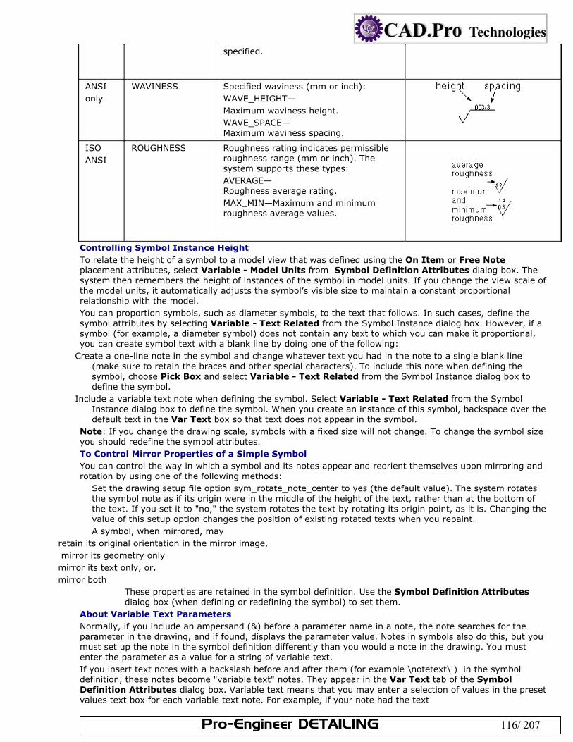
Pro-Engineer DETAILING 116/ 207
specified.
ANSI only
WAVINESS Specified waviness (mm or inch): WAVE_HEIGHT— Maximum waviness height. WAVE_SPACE— Maximum waviness spacing.
ISO ANSI
ROUGHNESS Roughness rating indicates permissible roughness range (mm or inch). The system supports these types: AVERAGE— Roughness average rating. MAX_MIN—Maximum and minimum roughness average values.
Controlling Symbol Instance Height To relate the height of a symbol to a model view that was defined using the On Item or Free Note placement attributes, select Variable - Model Units from Symbol Definition Attributes dialog box. The system then remembers the height of instances of the symbol in model units. If you change the view scale of the model units, it automatically adjusts the symbol’s visible size to maintain a constant proportional relationship with the model. You can proportion symbols, such as diameter symbols, to the text that follows. In such cases, define the symbol attributes by selecting Variable - Text Related from the Symbol Instance dialog box. However, if a symbol (for example, a diameter symbol) does not contain any text to which you can make it proportional, you can create symbol text with a blank line by doing one of the following:
Create a one-line note in the symbol and change whatever text you had in the note to a single blank line (make sure to retain the braces and other special characters). To include this note when defining the symbol, choose Pick Box and select Variable - Text Related from the Symbol Instance dialog box to define the symbol.
Include a variable text note when defining the symbol. Select Variable - Text Related from the Symbol Instance dialog box to define the symbol. When you create an instance of this symbol, backspace over the default text in the Var Text box so that text does not appear in the symbol.
Note: If you change the drawing scale, symbols with a fixed size will not change. To change the symbol size you should redefine the symbol attributes. To Control Mirror Properties of a Simple Symbol You can control the way in which a symbol and its notes appear and reorient themselves upon mirroring and rotation by using one of the following methods:
Set the drawing setup file option sym_rotate_note_center to yes (the default value). The system rotates the symbol note as if its origin were in the middle of the height of the text, rather than at the bottom of the text. If you set it to "no," the system rotates the text by rotating its origin point, as it is. Changing the value of this setup option changes the position of existing rotated texts when you repaint. A symbol, when mirrored, may
retain its original orientation in the mirror image, mirror its geometry only mirror its text only, or, mirror both
These properties are retained in the symbol definition. Use the Symbol Definition Attributes dialog box (when defining or redefining the symbol) to set them.
About Variable Text Parameters Normally, if you include an ampersand (&) before a parameter name in a note, the note searches for the parameter in the drawing, and if found, displays the parameter value. Notes in symbols also do this, but you must set up the note in the symbol definition differently than you would a note in the drawing. You must enter the parameter as a value for a string of variable text. If you insert text notes with a backslash before and after them (for example \notetext\ ) in the symbol definition, these notes become "variable text" notes. They appear in the Var Text tab of the Symbol Definition Attributes dialog box. Variable text means that you may enter a selection of values in the preset values text box for each variable text note. For example, if your note had the text
Pro-Engineer DETAILING 117/ 207
"Drafter Name \names\," "names" would appear in the left window of the Var Text tab. You could enter a list of employees names in the right side area to select from when the instance is placed. When you place the instance, you can select a name to follow "Drafter Name" from a drop down list in the Custom Drawing Symbol dialog box. (Select the symbol and click Properties on the right mouse button shortcut menu to show the dialog box.) You may also enter a parameter as the preset value for the variable text, for example "&draftername". If there is a "draftername" parameter in the drawing, the symbol note will return its value. About Symbol Parameters You can include two types of parameters in a symbol:
Node parameters identifying nodes (if nodes are present in the symbol). Symbol definition parameters, or the top parameter set, identifying the symbol. The system replaces them
with the corresponding information when you add the symbol to the drawing. Fixed text appears the same for any instance of the symbol. You can use the following parameters in a symbol definition:
Any of the system parameters for drawings Any user-defined parameters &dwg_name &model_name &scale
Note: You cannot use a note parameter for the value of variable text. Depending on the application, a symbol includes the following categories of parameters:
Required Optional, system-defined Optional, user-defined
If an application uses a symbol with required parameters, but they are missing, the system issues an error message and you can edit the symbol parameter file. Pro/ENGINEER uses symbols containing an individual parameter set to create electrical diagrams. You can define Pro/DIAGRAM symbols in Drawing mode and Diagram mode. However, if you want to use them in Pro/DIAGRAM, you must define them as components or connectors by providing the parameter set appropriate for the type of object the symbol represents (component or connector). To Generate a Parameter Set To create a parameter set, you can do one of the following:
Generate a set of default parameters by reading in data (system- or user-defined). Type parameter names and their values in a table using the Pro/TABLE environment. To Generate a Set of Default Parameters You can generate a set of default connector or component parameters to symbols. This is a Pro/Diagram specific function. Click Format > Symbol Gallery. The SYM Gallery menu appears. Click Symbol > Refine to locate the symbol to assign default parameters. Click SYMBOL EDIT > Parameters > Read. Using the READ SYM PRM menu, do one of the following:
Click Comp Default and retrieve a system set of default parameters for components. Click Conn Default and retrieve a system set of default parameters for connectors. Click Other and retrieve a user-specified file (with the extension ".spm") containing the appropriate
parameters. To Edit Symbol Parameters Once you have created a parameter set, you can modify symbol and node parameters by editing the parameter file using the Pro/TABLE editor. You can change the parameter value, add user-defined parameters, or delete parameters. If the system encounters errors after you have edited the parameter file, it displays an Information Window indicating the type of errors. You can use commands in the REEDIT menu to resolve the discrepancies. To View Symbol Parameters Using the Show command in the SYM PARAMS menu, you can view the symbol definition parameter set. Click Format > Symbol Gallery. The SYMBOL menu appears. Click symbol > Refine to locate the symbol to view parameters. Click SYMBOL EDIT > Parameters > Show. To Store a Symbol Parameter File
Pro-Engineer DETAILING 118/ 207
While working with a symbol definition, you can save the parameter set to a file in your working directory, and read it in later to create similar parameter sets for other symbol definitions. Click Format > Symbol Gallery. The SYMBOL menu appears. Click Symbol > Refine to locate the symbol to store parameters. Click SYMBOL EDIT > Parameters > Write. Type the filename without an extension. The system stores the file with the name "filename.spm" to disk. If the name that you typed for the parameter file already exists in your working directory, type [Y] to replace
the existing file or [N] to avoid overwriting; then type a new filename. About Adding Nodes While defining symbols or after defining them, you can add nodes (also referred to as pins) as valid wire attach points on components and connectors. You can also generate, modify, store, and view parameter sets. If you include a node in a symbol, the system identifies it by placing its name in a note. When you create nodes during symbol definition, it automatically adds the PIN command and node name value to the symbol parameter file. The drawing setup file option node_radius controls the display of nodes in symbols. To Create a Node Click Format > Symbol Gallery > Redefine to retrieve the symbol to include a node. The symbol edit
window opens. In the SYM EDIT dialog box, click Insert > Node…. The SYMBOL NODE menu appears. Click Make Node. Type the node name in numeric or alphanumeric form. Select the node location on the symbol. A green dot indicating a node with the node name appears on the
symbol. To Blank Parameters in Node Notes By default, the system shows node notes when it creates them. To blank all node notes: Click Format > Symbol Gallery >Redefine to retrieve the symbol that includes a node. Click Insert > Node…. The SYMBOL NODE menu appears. Click Hide Node Notes. To redisplay them, choose Show Node Notes. Referencing Parameters in Node Notes You can edit node notes as text to include the following references to other parameters:
Node name, for example, &node_name Node parameters, for example, &signal_name Top-level symbol parameters, for example, &ref_des Any valid drawing parameters included as labels, for example &scale
Note: You can reference only those symbols to which you have assigned values in the symbol parameter set. If you delete a parameter that a note references, "***" appears in the note instead of the missing parameter value.
About Manipulating Symbol Instances Just as you might modify the value or location of drawing dimensions, you can modify symbol instances in your drawings. You can alter any of the symbol attributes as necessary. You can apply any changes to the symbols individually or you can update all instances throughout the entire drawing by redefining the symbol definition. The following actions are typically applied to individual symbol instances:
Adjust the symbol height Change the angle at which the symbol is displayed Reposition the origin of the symbol Modify the symbol group attributes Edit the variable text values Convert the instance to draft entities Reattach instances and add new leader lines To ensure that the changes are available for another drawing session, you should modify and save the symbol definition within the symbol directory. To Modify a Symbol Instance Select the symbol instance in the drawing. Right-click and click Properties from shortcut menu. The Custom Drawing Symbol dialog box opens. Make any of the following modifications as necessary:
The leader or placement type. The symbol height (if it is allowed in the definition).
Pro-Engineer DETAILING 119/ 207
The rotation angle. The color or the origin. The groups displayed (If groups are set up in the definition). The variable text values (if variable text is set up in the definition). In the Symbol Instance dialog box, click
the Variable Text tab. Preset values are listed in a drop down list next to each parameter. The predefined values are part of the symbol definition.
When you are finished, click OK to update the display of the instance. To Edit the Symbol Leader Attachment You can edit leader attachment references and display or add additional attachment to symbol instances in your drawings. Select the symbol whose leader attachment you wish to modify. Be sure to select the symbol and not just the
symbol leader. Right-click and click Edit Attachment from the shortcut menu. The menu manager opens.
To move the attachment point to another reference, click Change Ref. To add a new attachment reference for the symbol, click Add Ref. To maintain the same references click Same Ref. This maintains the current status of attachment. If you are adding or changing an attachment, you need to define the attachment type. First, you should
define the references for the symbol: On Entity— On Surface— Free Point— Midpoint— Intersect— Define the physical attributes for the leader at the attachment point:
Arrow Head Dot Filled Dot No Arrow Slash Integral Box Filled Box Double Arrow After defining the leader attachment, click Done. The leader is modified. To Convert Symbols to Draft Entities You can convert a drawing symbol to a draft entity, which enables you to... Select the symbol to convert. Click Edit > Convert to draft entities. Any leaders are removed and the symbol is reduced to independent
graphic elements and text. To Relate a Symbol Instance to Drawing Objects You can relate a symbol to a dimension, note, or another symbol, so that the symbol follows the dimension throughout the drawing, thus making sure the symbol and related object stay together. After relating the symbol, you can adjust the offset the distance by dragging the symbol to a new location. To Relate Symbols Using Groups After placing the symbol in the drawing, select the symbol you want to relate to another object. Click Edit > Group > Relate to Object. Select the dimension, note, or symbol to relate the symbol to. The symbol is now related. To Relate Symbols Using Placement References In order to relate a symbol using placement references, you must select Free as one of placement type attributes in the symbol definition. After placing the symbol in the drawing, select the symbol. Right-click and click Properties. The Custom Drawing Symbol dialog box opens. Under Placement, select Offset from the Type box. On the drawing, select the dimension to relate the symbol to. If necessary, drag the dialog box to see the
dimensions on the drawing. The dimension highlights. To reposition the symbol, middle-click on the desired symbol location. The symbol relocates and highlights.
Pro-Engineer DETAILING 120/ 207
Click OK on the dialog box. The symbol is related to the dimension and will maintain the offset distance wherever the dimension is located.
To Control Text During Symbol Rotation If you are rotating a symbol you may want to set controls to manage the orientation of any text contained within the symbol. By doing so you can ensure that the text meets the appropriate standards and is readable. You can control the text during symbol rotation in the following ways:
Define the text behavior within the symbol definition. By setting the Fixed Text Angle symbol attribute, the text will maintain its orientation no matter how the symbol is positioned.
Example 1. The symbol in its original position. Example 2. The symbol created when using the Fixed Text Angle check box. Example 3. The symbol created when using Fixed Text Angle and rotating the symbol during instance creation.
Set the sym_flip_rotated_text drawing setup file option, which flips the text to the opposite side of a rotated symbol. By setting sym_flip_rotated_text to yes (the default is no), while the symbol orientation is +/- 90 degrees, any text defined in the Attributes box of the Symbol Definition Attributes dialog box menu simultaneously rotates and flips with the symbol.
Updating Symbol Instances As you dimension and detail your models you may need to redefine or retrieve an alternate version of a symbol. And, while it is not necessary, you may also want to update all instances of that symbol to reflect the symbol change throughout the current drawing. If you do not update the symbol in the current drawing, any newly added instances will maintain the symbol's old attributes. The process of updating symbols is largely dependent upon the relationship between the symbol and the directory in which it is stored. Similar to the way that the Windows operating system does not consider two files with the same name to be the same file if they are stored in different directories, Pro/E does not consider two symbols with the same name but different paths to be the same. For example:
Symbol Directory Symbol Name
Description
symbol directory (pro_symbol_dir)
ptc.sym
If the symbol is retrieved from the symbol directory set by the pro_symbol_dir configuration option its full name is simply <symbol_name>.sym.
C:\PTC\files\symbols C:\PTC\files\symbols\ptc.sym
If a symbol is retrieved from a location other than the symbol directory, its full name is <full_path_to_directory>\<symbol_name>.sym.
If the existing symbol instances’ full name does not match the full name of the symbol being retrieved, Pro/E does not prompt you to update the existing symbol instances. Instead, the new symbol instance is given the name <symbol_name>(2). This symbol renaming can be avoided by retrieving new symbol instances from the same symbol directory. If you do not remember the symbol name or storage directory, click Format > Symbol Gallery > Show Name and select the desired symbol instance. The full symbol name is displayed in the message area. Note: Pro/E is case sensitive when determining whether the symbol names match; C:\MyFiles is not the same as C:\myfiles. To Update Symbols in Drawings If you change or modify a symbol instance, you may also want to update all instances of that symbol to reflect the changes throughout the current drawing. In order for Pro/E to prompt you to update the symbol instances, you need to retrieve the new symbol from the same directory as the original symbol.
Pro-Engineer DETAILING 121/ 207
If the symbols are retrieved from separate directories the new symbol is renamed. To Update Drawing Symbols Retrieved from the Same Directory Click Format > Symbol Gallery. The SYM GALLERY menu appears in the menu manager. Click Redefine. The GET SYMBOL menu appears. Click Retrieve. The Open dialog box opens. Browse to and open the desired symbol. If the symbol file names are the same, you are prompted to update
all instances. Type [Y] to update all instances of the symbol in the current drawing to the most recent version. The
symbols are updated throughout the current drawing. To Update Drawing Symbols Retrieved from Different Directories If the existing symbol instances were retrieved from a different directory than the new symbol, there are a few alternate techniques available:
Manually replace the existing symbol instances with the new instance. Copy the new symbol to the directory specified in the full name of the existing instances. For example, if the full name of the existing instances is C:\PTC\files\symbols\ptc.sym, copy the new version of ptc.sym to C:\PTC\files\symbols. Ensure that the new version of the symbol has a higher revision number than the old one. The revision of each symbol is shown after the .sym extension. For example, ptc.sym.2 has a higher revision than ptc.sym.1. Then retrieve the new symbol instance. Write the existing symbol instances to disk in the symbol directory. Click Format > Symbol Gallery > Write > Pick Inst and then select an existing symbol instance. This will change the full name of the existing symbol instances to <symbol_name>.sym. Copy the new version of the symbol to the symbol directory, ensure that the new version of the symbol has a higher revision than the old one, and retrieve the new symbol instance. If the existing symbols were retrieved from the symbol directory and the new symbol is located elsewhere, set the symbol directory to the location of the new symbol before retrieving it.
About Drawing Datum Targets Use datum targets to indicate critical measurement points on the plot. The target is drawn inside a scalable circle with a leader. You can create a datum target specifying any set datum point, except one that has been created using Offset Csys. Simple datum targets reference a selected set datum point on a surface or edge. Diameter datum targets contain a required diameter. When a target is added, the lower part of the circle references the datum name, and adds an integer to note the instance of the target symbol; for example, DTM5 becomes DTM51, DTM52, etc. Draft targets do not resequence themselves if you delete one of them. For example, if there are three datum targets (B1, B2, and B3), deleting B2 leaves B1 and B3, not B1 and B2. Using the Show/Erase dialog box, you can show datum targets in multiple views. To Show Datum Targets Click View > Show and Erase. The Show/Erase dialog box opens. Click Show.
Under Type, click . Use the options tab to filter what datum targets you want to show up in the drawing:
Erased—Show previously erased items. Never Shown—Show items that you have yet to show in the drawing. Under Show By, define where you want to display the datum targets:
Feature—Show the datum targets for a particular feature on the drawing. Part—Show the datum targets for a particular part on the drawing. View—Show all the datum targets for the features and parts within a particular drawing view. Feature and View—Show the datum targets for a feature that repeats in several views in one
selected view. For example, if you have a feature to datum targets that shows in several projection views, you can use the Feature and View button to click the feature in the view in which you want to show it.
Part and View—Show the datum targets for a part that repeats in several views in one selected view.
Show All—Show all the datum targets within the drawing. Select the appropriate feature, part, or view to display the datum targets. You may need to repaint the
drawing for the datum planes to display. When the datum targets display the Preview tab opens. Of the datum targets previewed on the drawing, there may be some that you do not want to show. You
can filter these using the preview tab:
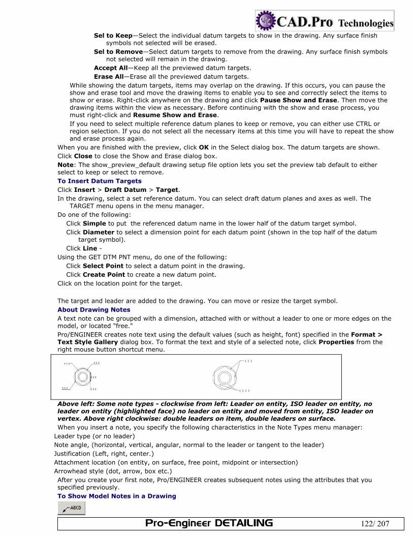
Pro-Engineer DETAILING 122/ 207
Sel to Keep—Select the individual datum targets to show in the drawing. Any surface finish symbols not selected will be erased.
Sel to Remove—Select datum targets to remove from the drawing. Any surface finish symbols not selected will remain in the drawing.
Accept All—Keep all the previewed datum targets. Erase All—Erase all the previewed datum targets.
While showing the datum targets, items may overlap on the drawing. If this occurs, you can pause the show and erase tool and move the drawing items to enable you to see and correctly select the items to show or erase. Right-click anywhere on the drawing and click Pause Show and Erase. Then move the drawing items within the view as necessary. Before continuing with the show and erase process, you must right-click and Resume Show and Erase. If you need to select multiple reference datum planes to keep or remove, you can either use CTRL or region selection. If you do not select all the necessary items at this time you will have to repeat the show and erase process again.
When you are finished with the preview, click OK in the Select dialog box. The datum targets are shown. Click Close to close the Show and Erase dialog box. Note: The show_preview_default drawing setup file option lets you set the preview tab default to either select to keep or select to remove. To Insert Datum Targets Click Insert > Draft Datum > Target. In the drawing, select a set reference datum. You can select draft datum planes and axes as well. The
TARGET menu opens in the menu manager. Do one of the following:
Click Simple to put the referenced datum name in the lower half of the datum target symbol. Click Diameter to select a dimension point for each datum point (shown in the top half of the datum
target symbol). Click Line -
Using the GET DTM PNT menu, do one of the following: Click Select Point to select a datum point in the drawing. Click Create Point to create a new datum point.
Click on the location point for the target. The target and leader are added to the drawing. You can move or resize the target symbol. About Drawing Notes A text note can be grouped with a dimension, attached with or without a leader to one or more edges on the model, or located "free." Pro/ENGINEER creates note text using the default values (such as height, font) specified in the Format > Text Style Gallery dialog box. To format the text and style of a selected note, click Properties from the right mouse button shortcut menu.
Above left: Some note types - clockwise from left: Leader on entity, ISO leader on entity, no leader on entity (highlighted face) no leader on entity and moved from entity, ISO leader on vertex. Above right clockwise: double leaders on item, double leaders on surface. When you insert a note, you specify the following characteristics in the Note Types menu manager:
Leader type (or no leader) Note angle, (horizontal, vertical, angular, normal to the leader or tangent to the leader) Justification (Left, right, center.) Attachment location (on entity, on surface, free point, midpoint or intersection) Arrowhead style (dot, arrow, box etc.) After you create your first note, Pro/ENGINEER creates subsequent notes using the attributes that you specified previously. To Show Model Notes in a Drawing
Pro-Engineer DETAILING 123/ 207
Using the Show/Erase dialog box and (optionally) the Model Tree Window, you can show model notes in drawings. Note location within drawings is dependent upon their actual placement in the model. Unplaced notes appear in a default location when you show model notes in the drawing. You can use the text of a model note to create a drawing note by reading in a model note from a file. To Insert a Drawing Note When you insert a note, you click through a series of options to set up all of the note properties such as attachment type and location, leader style, and text postilion. Your selections are remembered as defaults for subsequent notes, until you change them. Click Insert > Note. The Note Types menu opens on the menu manager. Use the Note Types menu to
specify the note appearance and contents source: No Leader—You bypass any leader setup options and are prompted only for the note text and position on the
sheet. Leader— Leader attached to a specified point. You are prompted for the attachment style, arrow style, etc. ISO Leader—ISO style leader (underlines text). Same as above, with ISO style. On Item—Note is directly attached to selected item. You bypass any leader setup options and are prompted
only for the note text and an item to which to attach the note directly. Offset— Note is grouped with a selected dimension. You bypass any leader setup options and are prompted
only for the note text and a dimension from which to offset the text. The note is grouped with the dimension and moves when it moves. You can move the note independently of the dimension, this resets the offset. Note sources, either Enter for the keyboard or File to open from a file.) Leader orientation, (if a leader is used)
Standard—Uses the default leader type. Normal Ldr—Makes the leader normal to the entity; in this case, the note can have only one leader. Tangent Ldr—Makes the leader tangent to the entity; in this case, the note can have only one leader.
The note alignment, (Left, Center, Right) Text style. By default the note is made with the current style, or last one you used. Use Cur Style to select a new current style from a list of defined styles, or click Style Lib to define a new style. or select one from the library.
When you have finished the options in the Note Types menu, click Make Note. If you used one of the no-leader types, you are prompted for the note location, and then the note text. If you selected File for the source, a browser opens and you may select the file from your directories. If you selected the Enter option from the menu manager, the prompt line activates and the text symbol
palette appears. If you used one of the leader note types, two things happen at the same time:
1) The Attach Type menu opens on the menu manager, and 2) You are prompted to select an attachment point for the "arrow end" of the leader. Use the Attach Type menu first. There are three things to set up on this menu- the type of attachment point, the position of the attachment point or points, and the graphic style of the "arrow side" of the leader. To determine the type of attachment point, set the menu manager to one of the following: On Entity, On Surface, Free Point, Mid Point, or Intersect. Mid Point attaches to the center of a circle or arc, or the midpoint of a line. Intersect attaches to the intersection of two lines. For multiple leaders, you will hold down the Ctrl key to select multiple points. You will see the pick points highlighted. Each point will get a leader when the note is placed. You can combine different attachment points and arrow end styles if necessary.
Select the location for the note on the sheet. When you have finished selecting the attachment point or points, click OK in the Select dialog box, then click Done on the menu manager. You are prompted for the note position on the sheet.
Click the position for the note on the sheet. You are prompted for the note text. Enter the note text, either from the keyboard of from a selected file. If you typed a line, press Enter. The line blanks again so you can enter a second line if necessary. If there is no second line, press Enter again to place the note. The note is placed. You are returned to the menu manager to setup and place another note. If you want to adjust the placement of the note you just created, click Done Return on the menu manager. You exit the note routines, and you last note is selected for movement. Note: The text symbol palette, which appears when you enter text for the note from the keyboard, is usually used to enter symbols in note text. You can also enter symbols directly from the keyboard if you
Pro-Engineer DETAILING 124/ 207
need to. To enter keyboard symbol mode press Ctrl + A before you start typing. The keystrokes will be entered in symbol font. Press Ctrl + B to return to text mode.
To Create and Edit Custom Text Styles Use the Style Lib dialog box to create new text styles, as well as modify and delete existing ones. Click Format > Text Style Gallery. The Text Style Library dialog box opens. Click New…. In the New Text Style dialog box, type a name fin the Style Name box, select an existing style
from the Style Name list, or click Select Text…. Type a name in the Style Name box, select an existing style from the Style Name list, or click Select
Text.... After you have changed all attributes, click OK. To close the dialog box and save the changes, click Close (Cancel changes to Close after you make a
change). To Specify the Default Font By default, Pro/ENGINEER creates text in regular ASCII font. A thickened version of the system default font (the filled font) is also automatically available to you as an alternative font. You can specify the ISO font as the default font by setting the drawing setup file option default_font to isofont, or you can set any of the Pro/ENGINEER-supported fonts as the default for a particular drawing. In addition to those fonts, Pro/ENGINEER supplies the four auxiliary fonts listed in the following table and 41 TrueType™ fonts.
Leroy font set leroy
Calcomp Alphabetical font set cal_alf
Calcomp Greek and Mathematical Symbol set cal_grek
ISO font set isofont
The TrueType fonts are located in the Pro/ENGINEER loadpoint directory. Additional TrueType fonts can be purchased and placed into the loadpoint directory. TrueType fonts can take more time to repaint. Typically, any TrueType Font can be used by Pro/ENGINEER by placing it in the directory specified in the setup option pro_font_dir. By default, any fonts placed in the loadpoint directory appear in the pull-down list in the Text Style dialog box. You can use the Apply button on the dialog box to preview any font for selected text. The ATTACH TYPE Menu In Pro/DETAIL The Attach Type options determine how the "arrow end" of a leader is attached to an object, and what graphic is used at the leader end.
On Entity—Creates a leader that is attached to a model edge or draft geometry. Selecting the entity near its vertex locates the leader at the vertex.
On Surface—Locates the leader on model geometry or surfaces. You can select model geometry, threads, and datum surfaces. Once you make an attachment on a surface, if you reorient the view, the attachment remains. If the size of the surface changes, the system updates the leader point accordingly.
Free Point—Locates the leader anywhere on the drawing. You must have a Pro/DETAIL license to create a note using this command.
Midpoint—Locates the leader at the midpoint of a model edge or draft geometry. The next figure illustrates where you can find the midpoint of entities such as splines, arcs, circles, and ellipses.
Intersect—Locates the leader at the intersection of two model edges or two draft entities. Arrow Head—Creates a leader with an arrow head. Dot—Creates a leader with a dot. Filled Dot—Creates a leader with a filled dot. No Arrow—Creates a leader with no arrow. Slash— Creates a leader with a slash. Integral—Creates a leader with an integral. Box—Creates a leader with a box. Filled Box—Creates a leader with a filled box.
Double Arrow—Creates a leader with a double arrow head. To Relate a Note to Dimension Text
Pro-Engineer DETAILING 125/ 207
When you relate a note to a dimension, the note moves with the dimension, retaining its position. Relating a Note at Time of Creation Follow the instructions in the topic To Add a Drawing Note, and use the Offset note type. You are prompted to select a dimension or other detail object from which to offset the note. Relating an Existing Note If the note is already placed use the following procedure to relate a note to a dimension: Select the note or notes to relate. Click Edit > Group > Relate to Object. Click the dimension to which to relate the note. The note is related to the dimension. To Enter a Note from a File You can keep note source text files in the working directory or you can set up a separate directory for them using the setup option "pro_note_dir." You can enter notes from a file that contain dimensions, parameters, special symbols, and superscripted or subscripted text. To use a text file as a note source, follow the instructions in the topic To Add a Drawing Note, and select File rather than Enter for the source choice. You are prompted to select a file from a browser to supply the note text. Creating and Saving Drawing Notes Using the Pro/ENGINEER Info menu, you can write the following information to a file:
Annotations to views. Notes with or without a leader, containing any number of lines. Parameters (the system substitutes parameters with their values after copying them to a file).
Notes written to disk using Info > Save Note are automatically appended with a .txt extension and a version increment extension. This causes notes to appear automatically in the menus when you retrieve them when you are creating notes. The system saves each selected note in a separate file. When specifying the name of a destination file, type the file name without an extension. The system then automatically appends the default .txt extension and a version increment extension (for example, note.txt.1). You can save notes with another extension (for example, note.ascii.1). The system uses your extension instead of .txt and appends a version increment extension (note.ascii.1). If you type the same file name as an existing file name, the system updates the version increment extension automatically so as not to overwrite an existing file (note.txt.2). Note: During the process, Pro/ENGINEER loses boxes and underlining information, and does not save special symbols. To save them, bring the note into a text editor and save it from within the editor. To Write Notes to a File From the Pro/ENGINEER menu bar, choose Info > Save Note. Select a note to save. Type the name of a destination file in the prompt line. To Add a Balloon Note Balloon notes consist of text enclosed in a circle. You can add them freely anywhere on the drawing, or attach them to any number of edges. When you enter multiple lines of text for the balloon note, the system encloses each line within a balloon, stacking them horizontally or vertically next to each other, depending upon whether you choose Horizontal or Vertical from the NOTE TYPES menu. The size of these related balloons is equal to the largest one necessary to enclose the longest text. Click Insert > Balloon. Click the appropriate commands from the NOTE TYPES menu on the Menu Manager. Click Done and select the leader type, if necessary. Select edges or the start point for the leaders; then click OK. Pick the location of the balloon note. Type the note text. Press Enter to start a new line, or press Enter twice to complete the note. To restrict the size of a balloon, use the drawing setup file options max_balloon_radius or min_balloon_radius. Text Strings When you are editing text, dimension values appear as follows:
@D (if displayed as a numerical value). @S (if displayed as a symbolic value). @O (if the dimension does not have a value, @O locates the text origin). Special characters appear between the control characters ^A and ^B.
Pro-Engineer DETAILING 126/ 207
When you edit a note, the system preserves all of the attributes (font, height, width, or slant angle) applied to a portion of the text. However, the note appears much different from how it does on the drawing. The system breaks up a text string into portions wherever there is a new line of text or a parameter (such as dimensions), and encloses each portion of the text in braces ({}), giving it an integer label. Labels identify the initial order of the text, and any attributes for that portion. When editing text, or adding more lines, you can copy the attributes of a portion of text by using the same integer label. Note: If you delete the special control characters when editing text, the text string changes. If you remove ^A, all special characters become their ASCII equivalent; if you remove ^B, all text that follows becomes a special character. You can edit view-related notes, such as section, detail, and scale notes; however, be sure not to delete or otherwise alter symbols that represent the name or scale of the view. If you edit these symbols, the system ignores the change, and displays the original note:
&view_name—name of the view &view_scale—name of a general scaled view &det_scale—scale of a detailed view
If you set the view_note option in the drawing setup file to std_din, you can create a view-related note with the words SECTION, DETAIL, and SEE_DETAIL omitted. This only affects the creation of view-related notes. If you switch from std_ansi to std_din, the system does not update view notes. To Modify Text Style To change the style assigned to selected text: Select a note or text to modify. Click Format > Text Style. The Text Style dialog box opens. Use the dialog box to edit the format properties. Click Apply to see the changes, click OK to save changes. Note: If you change the style assigned to note text, you can quickly change
other text strings to the same style using the Repeat Last Format Icon. Select the text or note you want to modify then click the icon. The last selected style is applied to the selection. To Modify a Style Definition To modify a style definition, Click Format > Text Style Gallery. The Text Style Gallery dialog box opens. Select the style to modify and click Modify. The Modify Text Style dialog box opens.
Use the dialog box to make changes to the style definition. Click OK when finished. To Modify Selected Text Color Click Format > Text Style. Select text; then click the middle mouse button to complete. The Text Style dialog box opens. In the Text Style dialog box, select the Color box. In the Color dialog box, select a system color, then click OK. The system displays the selected text in the
specified color and closes the Color dialog box. To reset the text to the old style, click Reset.. To reset selected text to its intrinsic color, click Intrinsic in
the Color dialog box. To Wrap Note Text When a note is created the text string is entered as one line. Use this procedure to wrap the text to a desired width. Select the note. The text is highlighted and "handles" appear on either side of the string. Use the cursor to drag the right side text area handle to the desired width. The text wraps according to the
width of the text area. If you add text to a note, the new text is not wrapped. To wrap it, you can either
Re-drag the text box to the desired width, or Select the note and from the right mouse button pop up menu, click Wrap Text. The note is wrapped to the
longest line. The Text Style Dialog Box You can change the font, width, and color of an existing text style. However, the system does not automatically update any text to which you previously assigned that text style (that is, before you modified it). The changes that you make using this dialog box only affect text to which you assign a text style after modifying it. Using the Text Style dialog box, you can:
Change the font by selecting a font name from the Font list.
Pro-Engineer DETAILING 127/ 207
Change the text by clearing the Default check box and typing a value in the Height box. Change the width by clearing the Default check box and typing a value in the Width Factor box. Change the thickness by clearing the Default check box and typing a value in the Thickness box. Change the slant angle by typing a value in the Slant Angle box. Underline the text by selecting the Underline check box. Change the line spacing by clearing the Default check box and typing a value in the Line Spacing box. Rotate the text at an angle by typing a value in the Angle box.. Specify the horizontal justification by selecting a value from the Justify Horiz list. Specify the vertical justification of table cell text in individual table cells by selecting a value from the Justify
Vert list. Flip the text so that it reads backwards by selecting the Mirror check box To mirror a note, you must first
select it; then select a mirror line.
Use the Break Crosshatching field to set an offset around a note if it is within a crosshatched area. To Enclose Notes in Text Boxes To enclose words or characters in a box, type "@[" before and "@]" after the text. For example: @[Notes in drawings@] puts the box around the entire text string. @[Notes@] in drawings puts the box around the word "Notes." To Create Superscripted and Subscripted Text To create superscripted text, type [@+text@#]and to create subscripted text, type [@-text@#],where text is the note text that is superscripted or subscripted. You can superscript or subscript plain text and special symbols; however, you cannot super- or subscript dimensions, instance numbers, other parameter values, or geometric tolerances. You can create superscripted and subscripted text as a separate note or include it in a text line with regular text on either side of it, and then modify it independently of the rest of the text line in which it appears. The system positions the text in reference to the closest line of regular text, whether that text is part of another note, or part of the note currently being created. To Specify an Existing Text Style as the Current Style As you create a note, you can apply an existing text style by choosing Cur Style from the NOTE TYPES menu manager. When you change the current style from the default to another text style, it only affects new notes, balloon text, symbols, and table text. If you choose Default from the SEL STYLE menu, the system uses the style that is defined by the drawing setup file options drawing_text_height, text_width_factor, and text_thickness. To Change Text Strings Select the text string to modify. The text is highlighted. Right-click and click Properties from the shortcut menu. The Note Properties dialog box opens. Click the Text tab. Edit the text string as necessary. When you have completed the changes, either save the note or click OK to
return to the drawing. To Place Draft and Reference Dimensions in Notes and Tables You can place draft (add and dd) dimensions and reference (rd) dimensions parametrically in drawing notes and tables using the format &add or &dd. Draft (driven) dimensions and reference dimensions created in the drawing are updated when the model is regenerated. Adding Special Text Characters to Notes When typing text strings into notes, you can use special text characters, special symbols, and drawing symbols. You can add special symbols to text strings in notes by typing them from the keyboard, the palette window, or a text file. For a table listing all of the special symbols available with Pro/ENGINEER, as well as their definitions and ASCII character representations, see the Pro/ENGINEER Installation and Administration Guide. Whenever you want to display the characters & or @ in the text of a note, you must type them twice. For example, type [See Views 1 && 2 @@ Sheet 3] for the note to read See Views 1 & 2 @ Sheet 3. Adding Drawing Symbols to Notes You can include a drawing symbol in a note if its instance is present in the drawing. To include a symbol, use the following format:
&sym(<symbolname>) Type the symbol filename without an extension.
Pro-Engineer DETAILING 128/ 207
Note: You cannot call out drawing symbols in dimensions that are stored with the model (those of type d or ad).
When you include an instance of a generic symbol, after you type the symbol name, select groups that compose the instance (this is similar to creating instances of a generic symbol). For example, if a drawing contains an instance of the symbol bevel, to include the symbol in a note, type [&sym(bevel)]. When you edit a note, the system represents the symbol in the following format:
n:&sym(sym_path) where n is the number of the text element, and sym_path is the name or pathname of the symbol. Note: Pro/ENGINEER displays a drawing symbol in the text note to which it is added, but it does not display it in the dimension text line. Dimension text resides in Part mode; therefore, it may not acquire drawing symbols that reside in Drawing mode. To Include the Symbol: Click Insert > Note. Type the note in the format described earlier. Specify the symbol height. For an instance of a generic symbol, select groups to compose the instance. To complete the instance
description, type variable text, if necessary.
To finish the note, press the ENTER key twice. Including Parameter Information in Notes When you set the drawing set up file option yes_no_parameter_display to yes_no, parameters can have a yes or no value in drawing notes. When you set it to true_false (the default value), they can have a true or false value. To specify parameter information in a note, use the following format:
Dimensions—&d# or &ad#, where # is the dimension ID. Examples: &d12. &ad5. Reference dimensions—&rd#, where # is the dimension ID. Example: &rd2. Instance number—&p#, where # is the parameter ID. Example: &p8 User-defined parameters—&xxxx where xxxx is a symbol defined in a relation. Datum names—&dtm_name, where name is the name of a datum plane. Drawing labels—You can add the following drawing labels to a drawing:
&todays_date—Adds the date as of the note’s creation in the form dd-mm-yy (for example, 2-Jan-92). If you include this symbol in a format table, the system evaluates it when it copies the format into the drawing.
&model_name—Adds the model used for the drawing. &dwg_name—Adds the name of the drawing. &scale—Adds the scale of the drawing. &type—Adds the drawing model type. &format—Adds the format size. &linear_tol_0_0 through &linear_tol_0_000000—Adds the linear tolerance values for one to six decimal
places. &angular_tol_0_0 through &angular_tol_0_000000—Adds the angular tolerance values for one to six
decimal places. ¤t_sheet—Adds the sheet number for the sheet on which the note is located. &total_sheets—Adds the total number of sheets for the drawing.
Drawing parameters—¶meter:d, where parameter is the parameter name. Erasing a Note Erasing a note does not delete it from the drawing. The system also hides any dimensions or parameters that are included in the erased note, and does not return them to their original locations elsewhere in the drawing. Select the note to erase. Click Erase from the right mouse button shortcut menu. The note is erased.
To show erased notes, click View > Show and Erase. Use the Show tab, and the notes icon. About Note Parameters In addition to text and special symbols, notes can include model dimensions, pattern instance parameters, symbols, drawing labels, and drawing parameters. The drawing setup file option yes_no_parameter_display controls the display of yes/no parameters in drawing notes and tables.
Pro-Engineer DETAILING 129/ 207
When specifying parameter information in a note, keep in mind the following restrictions: When you include dimensions in notes, the system removes them from their originally-assigned views. You cannot add draft dimensions (associative—add # or nonassociative -dd#) to a note. A datum name in the note is read-only, so you cannot modify it; unlike dimensions, a datum name does not
disappear from the model view if it is included in a note. The system encloses its name in a rectangle, as if it were a set datum.
You cannot use drawing labels in drawing relations; you can only use them in drawing notes and tables. When the note appears, the system replaces dimensions and parameters by the corresponding numerical
values. If you set the configuration file option switch_dims_for_notes to yes, dimensions appear as their symbolic values during note creation. If you set it to no, they remain as numerical values.
Before referencing a model in a parametric note, make sure that you add this model to the drawing. Otherwise, the system does not evaluate the model parameter referenced in the note.
You can include a gtol symbol in a note by entering it as a parameter; however, you cannot include global parameters (that is, parameters created in a layout) and draft dimensions in notes.
To Control the Format of the Date The configuration file option todays_date_note_format controls the initial format of the date displayed in a drawing. The format for the setting is a string consisting of three portions: the year, the month, and the date. You can enter the portions in any order. The default value is %dd-%Mmm-%yy.
Year %yy, for 97 %yyyy, for 1997
Month (if the month contains two digits (for example, 10),% mm, % m, or % m all produce the same result) %Mmm, for Jan %MMM, for JAN %Month, for January %MONTH, for JANUARY %mm, for 01 %m, for 1 % m, for <space>1 Date (if 2 digits are needed to represent the date, all three are the same. Therefore, "%dd %mm %yy" produces "01 01 97," and "%MMM %d %yyyy" produces "JAN 1 1997") %dd, for 01 %d, for 1 % d, for <space>1.
The following formats are also valid: %dd-%Mmm-%yy (= 01-Jan-97) %mm/%dd/%yy (= 01/01/97)
%Mmm %dd,%yyyy (= Jan 01, 1997) To Include a Feature Parameter in a Note To include a feature parameter in a note, use this format:
&<param_name>:FID_<feat_ID> or
&<param_name>:FID_<FEAT_NAME> To Include a Model Note in a Drawing Note To include a model note in a drawing note, use the format &<param_name>. To Display Pro/PDM Data You can display the name of a model’s product database on a drawing sheet, as well as the model’s revision in that product database and its release level, by entering the following in a note:
To display the model’s product database of origin, enter the parameter &PDMDB. To display the model’s revision, enter the parameter &PDMREV. To display the drawing’s revision number, enter the parameter &PDMREV:D.
To display the model’s release level, enter the parameter &PDMRL. To Reference Parameters Assigned to Objects In model and drawing notes, to reference parameters that you assigned to objects in Part or Assembly mode, use this format:
For edges:
Pro-Engineer DETAILING 130/ 207
&<param_name>:EID_<edge_name> For surfaces:
&<param_name>:SID_<surface_name> For other objects:
&<param_name> To Reference a Mass Properties Symbol in a Note You can create a parametric note that references a mass properties symbol. After the geometry changes, you can update the note to reflect the latest value of the mass properties parameter. Set a user-defined parameter. For example: [volume]. Add a relation, assigning this parameter to a mass properties symbol that you want to reference in a note.
For example: volume = mp_volume("").
Add a note containing the user-defined parameter. For example: [&volume]. To Update a Parametric Note Regenerate the model. Do one of the following:
Manually recompute mass properties by choosing Analysis > Model Analysis....
Include a MASSPROP statement in the program of the model using Pro/PROGRAM. Controlling the Number of Decimal Places in Parameters When you append certain parameter symbols with the characters "[.#]", the system displays those parameters with the number of decimal places specified by #, which is an integer. The system rounds the number, but uses the same value. This applies to the following parameters:
User-defined model parameters or those defined in model relations Drawing labels, such as &scale (drawing scale) and &det_scale (detail view scale) When adding the note that contains the parameter, append the parameter symbol with "[.#]", where # is the number of decimal spaces to appear. For example, if a detailed view scale is 1.125, and you want to display only two decimal places, change the drawing label to &det_scale[.2] (no spaces). This displays the scale note as 1.13. To edit the note, select it and click Properties from the right mouse button shortcut menu. Restrictions with Dimensions and Other Model Parameters You cannot use this functionality on dimensions or other model parameters, such as pattern parameters. However, if you make a user-defined parameter equal to the model parameter, and then add the user-defined parameter to the note, you can control the display of the model parameter decimal places. To Show the Scale of an Individual View The drawing parameter scale_of_view_x evaluates the drawing scale of whichever view has name X.
For example, to call out the scale of a view named DETAILED_BAR, type &scale_of_view_detailed_bar. Example: Parameters in Notes The following example illustrates the parameter’s usage in notes: In Part mode, assign the name "A" to a surface. Create a parameter with a name "RAD," of type Number. Assign a value ".03" to this parameter. In Drawing mode, create a note by typing [Break sharp edge with R = &RAD:SID_A]. This note appears:
"Break sharp edge with R =.03". If a drawing note has a single attachment (defined using On Item or one leader line), you can show the parameters of the entity to which it is attached by typing the following string into the note: ¶m_name:att. The system then interprets the param_name in a series of contexts until it is able to evaluate it successfully. First, it searches the immediate entity to which the note is attached, such as an edge. Next, it searches the feature that owns the entity. If it still cannot evaluate the parameter, it then searches the model that owns the feature. Finally, if applicable, it searches the component that refers to the model. If you want to specify the exact context in which to interpret the parameter, specify a full "att_" postfix instead. After you create the note, if you choose Switch Dimensions from the Pro/ENGINEER Info menu, the system appends the "att_" postfix to specify the exact context in which it interprets the parameter.
Param_name:att_edge Edge
Param_name:att_feat Feature
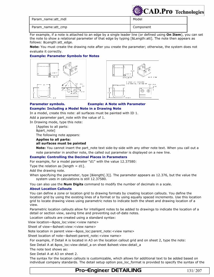
Pro-Engineer DETAILING 131/ 207
Param_name:att_mdl Model
Param_name:att_cmp Component
For example, if a note is attached to an edge by a single leader line (or defined using On Item), you can set the note to show a relational parameter of that edge by typing [&Length:att]. The note then appears as follows: &Length:att_edge. Note: You must create the drawing note after you create the parameter; otherwise, the system does not evaluate it correctly. Example: Parameter Symbols for Notes
Parameter symbols. Example: A Note with Parameter Example: Including a Model Note in a Drawing Note In a model, create this note: all surfaces must be painted with ID 1. Add a parameter part_note with the value of 1. In Drawing mode, type this note:
[Applies to all parts: &part_note] The following note appears: Applies to all parts: all surfaces must be painted Note: You cannot insert the part_note text side-by-side with any other note text. When you call out a note parameter in another note, the called out parameter is displayed on a new line.
Example: Controlling the Decimal Places in Parameters For example, for a model parameter "d1" with the value 12.37580: Type the relation as [length = d1]. Add the drawing note. When specifying the parameter, type [&length[.3]]. The parameter appears as 12.376, but the value the
system uses in calculations is still 12.37580.
You can also use the Num Digits command to modify the number of decimals in a scale. About Location Callouts You can define a zone or location grid to drawing formats by creating location callouts. You define the location grid by using the existing lines of a format or by using equally spaced increments. Use this location grid to locate drawing views using parametric notes to indicate both the sheet and drawing location of a view. Parametric location callouts allow for intelligent notes to be added to drawings to indicate the location of a detail or section view, saving time and preventing out-of-date notes. Location callouts are created using a standard syntax:
View location—&pos_loc:view:<view name> Sheet of view—&sheet:view:<view name> Note location in parent view—&pos_loc:parent_note:<view name> Sheet location of note—&sheet:parent_note:<view name> For example, if Detail A is located in A3 on the location callout grid and on sheet 2, type the note: See Detail A at &pos_loc:view:detail_a on sheet &sheet:view:detail_a The note text shows as: See Detail A at A3 on sheet 2. The syntax for the location callouts is customizable, which allows for additional text to be added based on individual company standards. The detail setup option pos_loc_format is provided to specify the syntax of the
Pro-Engineer DETAILING 132/ 207
pos_loc and sheet parameters in the callout. The default of pos_loc_format is %s%x%y, and appears as 2D4. %r added to pos_loc_format will repeat the syntax string for the same item appearing several times in different locations. This applies to items such as symbols and connectors, but not to views because views have unique names. The syntax will be %s%x%y, %r where %r means to repeat the substring from the first special character to the last. &pos_loc Behavior: The location note updates upon regeneration if the view is moved on the drawing. If the view is erased or moved outside of the grid, the value of the location callout changes to ***. The callout updates when the view is resumed or the view is moved back onto the grid. If the view is deleted, then the location callout is no longer parametric and the value changes to ***. &sheet Behavior: If you switch the view to a different sheet, the location callout automatically updates to the new sheet number. If the view is erased, the value of the location callout changes to ***. The callout updates when the view is resumed. If the view is moved outside of the grid, the value remains as the correct sheet number. If the view is deleted, then the location callout is no longer parametric and the value changes to ***. You specify which corner of the location grid you want as the origin. The grid origin is shown as a yellow X. The default grid origin is the lower right corner of the location grid. To Define the Location Callout Grid Define a location grid on the format file (.frm) your drawing is referencing. In a Format file click File > Page Setup. The Location Grid menu opens on the menu manager. Click Define. Click one of the following to define:
Grid Outline—Specify the grid outline by using the rubberband box or by papersize (equal to the size of the page).
Grid Origin—Pick a point to indicate the grid origin. The lower right-hand corner is the default origin. Columns—Specify the amount and location of grid columns by number or pick points, and then specify
the grid labels by letter, number, or custom. Rows— Specify the amount and location of grid rows by number or pick points, and then specify the grid
labels by letter, number, or custom. Click Done/Return. To Show the Location Callout in a New Drawing In Drawing mode, click Insert > Note. Select the location for the location callout. Type a note, and then type the following:
To show the view location on the grid: &pos_loc:view:<view name> To show just the sheet location: &sheet:view:<view name> To show the note location in the parent view: &pos_loc:parent_note:<view name> To show the sheet location of the note: &sheet:parent_note:<view name>
Click Done/Return. The location callout is created. Example: A Location Callout To show the location of a view named Main_view, type the following in the Enter NOTE text box: Main_view is located in &pos_loc:view:main_view The note shows as: Main_view is located in 3B
According to the location callout grid you specified, Main_view is located in section 3B. About Cleaning Up Dimensions You can cleanup the placement of drawing dimensions to meet industry standards and enable easier reading of your model detailing. There are numerous ways to adjust the locations of dimensions, including:
Manually moving the dimension to the desired location on the drawing sheet. Aligning selected dimensions with a specific dimension. Automatically arranging the display of selected dimensions automatically by setting controls for dimension
placement and cosmetic attributes, like flip arrow direction. You can also adjust the display of the dimensions by:
Moving the dimensions to a different views
Pro-Engineer DETAILING 133/ 207
Toggling the Leader-to-Text Style Modifying the witness lines. Note: Cleaning up the dimension display can also be accomplished by customizing the dimension display, including controlling what values appear and how the text is formatted. To Erase Dimensions and Detailing Items You can remove both driving and driven dimensions from the display by erasing them. This does not delete them from the model. If you are only deleting a small number of dimensions, you may want to right-click on the dimension and select Erase. Otherwise, continue with the following: Click View > Show and Erase. The Show/Erase dialog box opens. Click Erase. Under Type, indicate which type of dimension or detailing item you wish to erase. You can select multiple
items. Under Erase By, where you want to erase the dimensions:
Selected Items—Erase individual dimensions from any location on the drawing. Feature—Erase dimensions for a selected feature. Feature & View—Erase dimensions for a selected feature within a view. Part—Erase dimensions for a part at the selected assembly location. Part & View—Erase dimensions for a selected part within a view. View—Erase all dimensions in the selected view. Erase All—Erase all dimensions in the drawing. Select the appropriate feature, part, or view to erase the dimensions from. You may need to repaint the
drawing for the dimensions to display. When you are finished with the preview, click OK in the Select dialog box. The dimensions are shown.
Click Close to close the Show and Erase dialog box. To Move Dimensions You can move dimensions within a view using the following procedure: Select the dimension you want to move. The cursor changes to a four-pointed arrow. Drag the dimension to the desired location. Note:
You can use the CTRL key to select multiple dimensions. If you move one of the selected dimensions, they all move with it.
You can move created (driven) dimensions by editing the attachment point of the dimension. Select the dimension and click Edit > Attachment. Select a new attachment point within the same view and middle click to place the dimension. Shown model dimensions can not be moved with this command, as it would require changing the reference within the model.
You move dimensions according to their X and Y coordinates using Edit > Move Special. To Move an Item Between Views You can move detailing items attached to the model with leader lines (or attached directly to an edge) from one view to another view of the same model. You can switch the view that dimensions appear in using the following procedure. If Pro/ENGINEER cannot display a dimension in the selected view, it issues a warning and does not move it. Select a item to move. Click Edit > Move Item to View. Select the view to which you want to move the item. The item is attached to the new view, and activated to
move for adjustment. Note:
When you select a patterned feature dimension, all dimensions of the pattern move. When you switch the view of an ordinate baseline, all ordinate dimensions that reference it also switch views. To Align Dimensions You can clean up your drawing display by aligning linear and radial dimensions. The selected dimensions align to the first dimension selected, provided that they share a parallel witness line. Any dimension that cannot be aligned with the selected dimensions will not move.
Select the dimension to which you wish to align other dimensions to. The dimension highlights. Press CTRL and select the remaining dimensions to align. You can select the additional dimensions individually or you can use region selection. Nondimension objects may also be selected, however, the alignment only applies to the selected dimensions. The selected dimensions highlight.
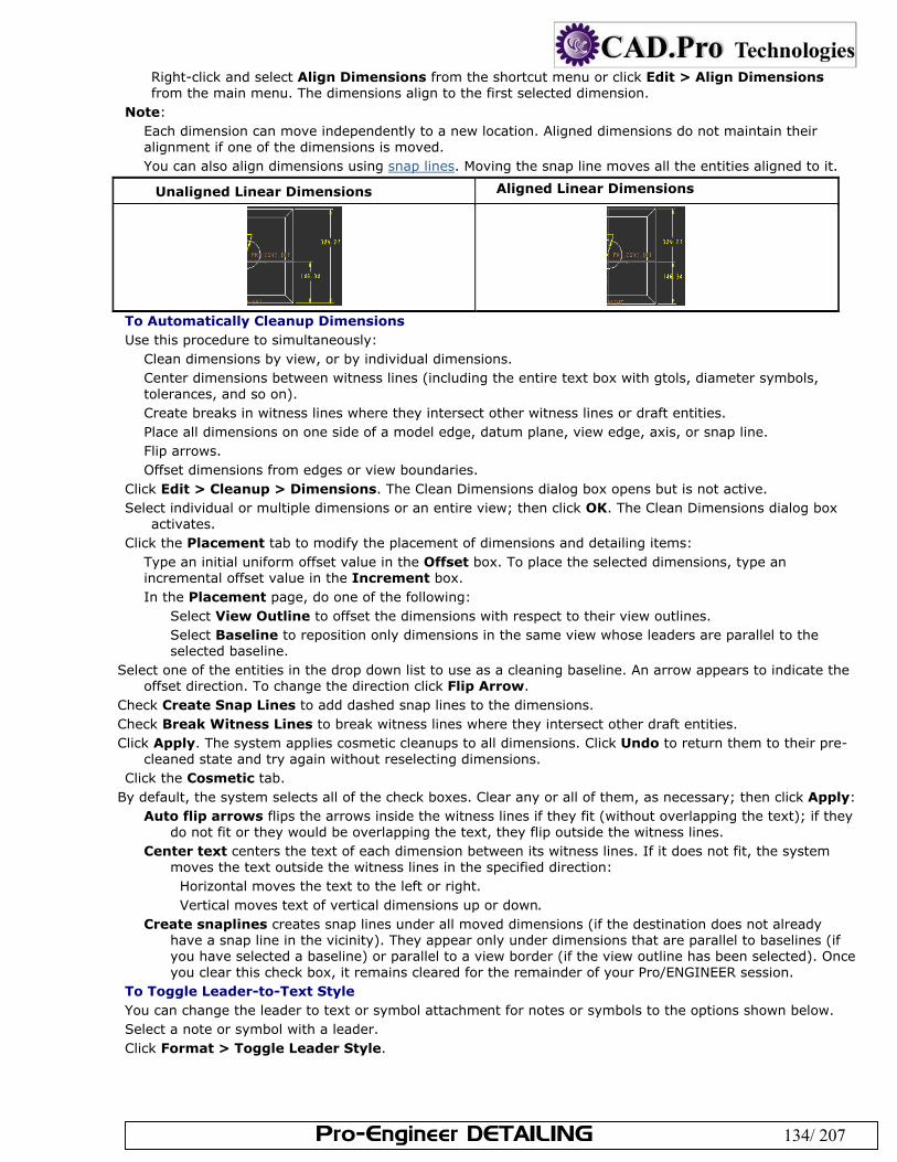
Pro-Engineer DETAILING 134/ 207
Right-click and select Align Dimensions from the shortcut menu or click Edit > Align Dimensions from the main menu. The dimensions align to the first selected dimension.
Note: Each dimension can move independently to a new location. Aligned dimensions do not maintain their alignment if one of the dimensions is moved. You can also align dimensions using snap lines. Moving the snap line moves all the entities aligned to it.
Unaligned Linear Dimensions Aligned Linear Dimensions
To Automatically Cleanup Dimensions Use this procedure to simultaneously:
Clean dimensions by view, or by individual dimensions. Center dimensions between witness lines (including the entire text box with gtols, diameter symbols, tolerances, and so on). Create breaks in witness lines where they intersect other witness lines or draft entities. Place all dimensions on one side of a model edge, datum plane, view edge, axis, or snap line. Flip arrows. Offset dimensions from edges or view boundaries.
Click Edit > Cleanup > Dimensions. The Clean Dimensions dialog box opens but is not active. Select individual or multiple dimensions or an entire view; then click OK. The Clean Dimensions dialog box
activates. Click the Placement tab to modify the placement of dimensions and detailing items:
Type an initial uniform offset value in the Offset box. To place the selected dimensions, type an incremental offset value in the Increment box. In the Placement page, do one of the following:
Select View Outline to offset the dimensions with respect to their view outlines. Select Baseline to reposition only dimensions in the same view whose leaders are parallel to the selected baseline.
Select one of the entities in the drop down list to use as a cleaning baseline. An arrow appears to indicate the offset direction. To change the direction click Flip Arrow.
Check Create Snap Lines to add dashed snap lines to the dimensions. Check Break Witness Lines to break witness lines where they intersect other draft entities. Click Apply. The system applies cosmetic cleanups to all dimensions. Click Undo to return them to their pre-
cleaned state and try again without reselecting dimensions. Click the Cosmetic tab.
By default, the system selects all of the check boxes. Clear any or all of them, as necessary; then click Apply: Auto flip arrows flips the arrows inside the witness lines if they fit (without overlapping the text); if they
do not fit or they would be overlapping the text, they flip outside the witness lines. Center text centers the text of each dimension between its witness lines. If it does not fit, the system
moves the text outside the witness lines in the specified direction: Horizontal moves the text to the left or right. Vertical moves text of vertical dimensions up or down.
Create snaplines creates snap lines under all moved dimensions (if the destination does not already have a snap line in the vicinity). They appear only under dimensions that are parallel to baselines (if you have selected a baseline) or parallel to a view border (if the view outline has been selected). Once you clear this check box, it remains cleared for the remainder of your Pro/ENGINEER session.
To Toggle Leader-to-Text Style You can change the leader to text or symbol attachment for notes or symbols to the options shown below. Select a note or symbol with a leader. Click Format > Toggle Leader Style.
Pro-Engineer DETAILING 135/ 207
.
Leader Options To Reroute Dimensions with Lost References Lost dimension references may occur when 3D parts or features are suppressed, or during feature redefinition. Lost references in a drawing are highlighted in a unique color. Click the lost dimension to reroute and then use the right-mouse button to use the shortcut menu. Click Edit Attachment to reroute the dimension to new references. To Delete Dimensions When working with added dimensions (dimensions created with the Insert command.) you can either erase or delete the dimensions. Deleting the dimensions permanently removes them from the drawing. Select the added dimension(s) you wish to permanently delete from the drawing. Right-click and select Delete on the shortcut menu, or click Edit > Delete. The dimension is deleted. Note: If you unintentionally deleted a dimension, you can undo all the deleted dimensions within that operation by clicking Edit > Undo Delete. About Formatting Dimension Display You can customize the display of dimensions within your drawings to meet your detailing requirements. The dimensions can either be formatted:
Individually using the Dimension Properties dialog box Globally using either drawing setup file and configuration options or the format menu Individually Formatting Dimensions The Dimension Properties dialog box (Edit > Properties) enables you to format the display of individual dimensions. The dimension must already exist in your drawing to access and customize its properties. The property settings only apply to the selected instances. From within the dialog box, you can:
Modify the dimension values and set tolerances. Set the display of dimensions to decimal or fractional format; as well as adjust the settings for decimal places,
trailing zeros, angular dimension units. Change the way dimension displays (basic or inspection). Format the positioning and decimal places for dual dimensions. Show and erase dimension witness lines. Modify the dimension text; including adding symbols, prefixes, and postfixes. Define the dimension text style; including font type, height, line spacing, and color. Note: You can modify the dimension properties by right-clicking the selected dimension and click Properties on the shortcut menu. Globally Formatting Dimensions You can format dimensions globally using either the Format menu or drawing setup file and configuration options. Once you define the dimension format setting, such as number of decimal places, the setting applies to all newly created or shown dimensions in the drawing. There are several drawing setup file options that contribute to the formatting of dimensions. You can easily find a complete listing if you sort the drawing setup file by category in the Options dialog box (File > Properties > Drawing Options). To Format Existing Dual Dimensions in a Drawing You can detail your model using dual dimension schemes, such as English and metric. The following procedure enables you to format the properties of an individual set of dimensions. Note: Before continuing, make sure dual dimensions are enabled with the dual_dimensioning drawing setup file option. Select the dimension to modify. Click Edit > Properties. The Dimension Properties dialog box opens. Click the Properties tab. Under Dual Dimension, define how to format the dimensions:
To place the secondary dimension below the primary dimension, select Below. To place the secondary dimension on the same line as the primary dimension, select To Right. To specify the number of decimal places to use for the secondary dimension, type a value in the Dual
decimal places box. Note:
Pro-Engineer DETAILING 136/ 207
If you are using metric dimensions as primary or secondary units in dual dimensions, the metric dimensions do not display as fractions if the fraction format is set.
When you are using dual dimensioning with dimensional tolerances, the system rounds the secondary values so that they always fit within the range indicated by primary units (that is, so that they are tighter than primary values), and retain the desired design intent.
To Show Dimensions in Fractional Format You can change the format of the dimensions to either decimal or fractional. Select the dimensions to convert from decimal to fractional format. Press CTRL or use region selection for
multiple selections. Right-click and click Properties from the shortcut menu. The Dimension Properties dialog box opens. Click the Properties tab. Under Format, click Fractional. You can specify a denominator.
Click Ok. To Set the Decimal Places and Trailing Zeros You can define the number of decimal places and trailing zeros for the dimensions within your drawing. The number can be set before or after the dimension is created or shown in a drawing. To Set the Decimal Places for Existing Dimensions Select the dimension or note with numeric text. Press CTRL or use region selection for multiple selections. You can set the decimal places and trailing zeros in either of the following ways:
Right-click on the selected dimensions and click Properties or click Edit > Properties. The Dimension Properties dialog box opens. On the Properties tab, under Format, click Decimal and then type a value in the Number of decimal places box.
Click Format > Decimal Places. You are prompted to type a number of decimal places. Type a value and press ENTER. Any dimensions selected, created or shown display with the designated number of decimal places and trailing zeros.
To Set the Decimal Places Prior to Displaying Dimensions Click Format > Decimal Places. You are prompted to type a number of decimal places. Type a value and press ENTER. Any dimensions created or shown display with the designated number of
decimal places and trailing zeros. You can also set the number of decimal places using the following options:
To change the default number of decimal places for non-angle dimensions, set the default_dec_places configuration option to a value of 0 through 14 (the default is 1).
To change the default number of decimal places for angle dimensions, set the default_ang_dec_places configuration option to a value of 0 through 14 (the default is 1).
Remove the trailing zeros to conform to ANSI standards by setting the draw_ang_unit_trail_zeros drawing setup file option to yes (the default). This applies only if the entire seconds or seconds/minutes field is exactly zero. Select Fractional and type [3600] in the Largest Denominator box to be sure.
To Show Angles in Degrees Select the dimensions to display in degrees. Press CTRL or use region selection for multiple selections. Right-click and click Properties from the shortcut menu. The Dimension Properties dialog box opens. Click the Properties tab. Under Format, select one of the following from the Angular Dimension Units list:
Degrees—Show the angular dimension in degrees Degrees, Min—Show the angular dimension in degrees and minutes Degrees, Min, Sec—Show the angular dimension in degrees, minutes and seconds. Click OK. The angular dimension is changed to the specified unit. Note: To change the angular dimension default setting, use the draw_ang_units drawing setup option. To Change the Dimension Arrow Directions You can flip through the various arrow directions for each text orientation setting. For example, when the text_orientation drawing setup file is set to parallel the Flip Arrows command will cycle through the following arrow displays:
You can flip the dimension arrow directions in the following ways:
Pro-Engineer DETAILING 137/ 207
Right-click on the selected dimension and click Flip Arrows on the shortcut menu. Select the dimension whose arrows you wish change. Click Edit > Properties and then click Flip Arrows under Display. While moving a dimension, you can simultaneously right-click and cycle through the displays for the designated text orientation setting.
Note: If necessary, you drag diameter dimensions within the circle being dimensioned. To Display Dimension Text Symbols The following procedure provides a more permanent replacement of dimensions with symbols. You can toggle the display of all dimensions temporarily by clicking Info > Switch Dimensions. Select the dimensions containing text to replace with symbols. Press CTRL or use region selection for multiple
selections. Right-click and click Properties from the shortcut menu. The Dimension Properties dialog box opens. Click the Dimension Text tab. In the Dimension Text box, note the current @D setting. Backspace over the D and replace it with an S.
Type a prefix or a postfix if you want to add text to the value of the dimension. Click OK. The selected dimensions now display their symbolic values rather than their dimension values.
Note: To change the dimension back to normal display, use the preceding procedure and modify @S back to @D or @O (for drawing dimensions that show text instead of a dimension value). You can replace the symbol without invalidating relations where the dimension appears. To Convert Diameter Dimensions to Linear You can convert a diameter dimension to a linear dimension, or convert a linear dimension for a diameter to a diameter dimension without switching the view. When you switch views on one of these converted dimensions, Pro/ENGINEER tries to display the dimension in the format type prior to the conversion, then in the converted format type, and finally in its original displayed view. Select the diameter dimension to convert to linear. Click Edit > Properties. The Modify Dimension dialog box opens. Select the Show as linear dimension check box and then click OK. Note: You cannot convert a linear dimension (for example, the depth of an extruded slot) to a diameter dimension. Using Driven and Reference Dimensions in Relations You can use driven ("ad" type) and reference dimensions on the right side of relations only (to drive the value of other dimensions or parameters). If you have used a driven dimension in a relation to drive a model dimension, the model dimension also changes until you regenerate the model in Drawing mode. You can use reference dimensions to drive model dimensions because they regenerate in Part or Assembly mode; however, you should not use driven dimensions to drive model dimensions because incorrect model dimensions might occur if you change the model in Part or Assembly mode. To add relations, use the Tools > Relations command. Switching to Dimension Symbols Use Info > Switch Dimensions to show the dimension symbol, and identify the symbol type. The figure below shows dimensions that have been switched to show their symbol displays. The letter combinations define the symbol type, and the number is a unique identifier for the dimension. The letter and number combination create a unique reference designator for the dimension that is used in advanced techniques such as defining relational formulas between dimensions.
d—Shown (driving) dimension created during feature creation in the model. These dimensions are associative bidirectionaly between the model and the drawing. ad—Created (driven) dimension which is associative to the model and stored with the model but cannot be modified in the drawing. These dimensions update in the drawing only when model geometry is modified. "ad" dimensions result when the config.pro options "create_drawing_dims_only" and "draw_models_read_only" have values of "no", which are the default values. add—Created draft dimension which is still associative to the geometry or draft entity which it references, but gets stored with the drawing. "add" dimensions result when the config.pro options "create_drawing_dims_only" or "draw_models_read_only" have values of "yes". To create "add" dimensions for referencing draft geometry, the Drawing Setup file option "associative_dimensioning" must be set to "yes".
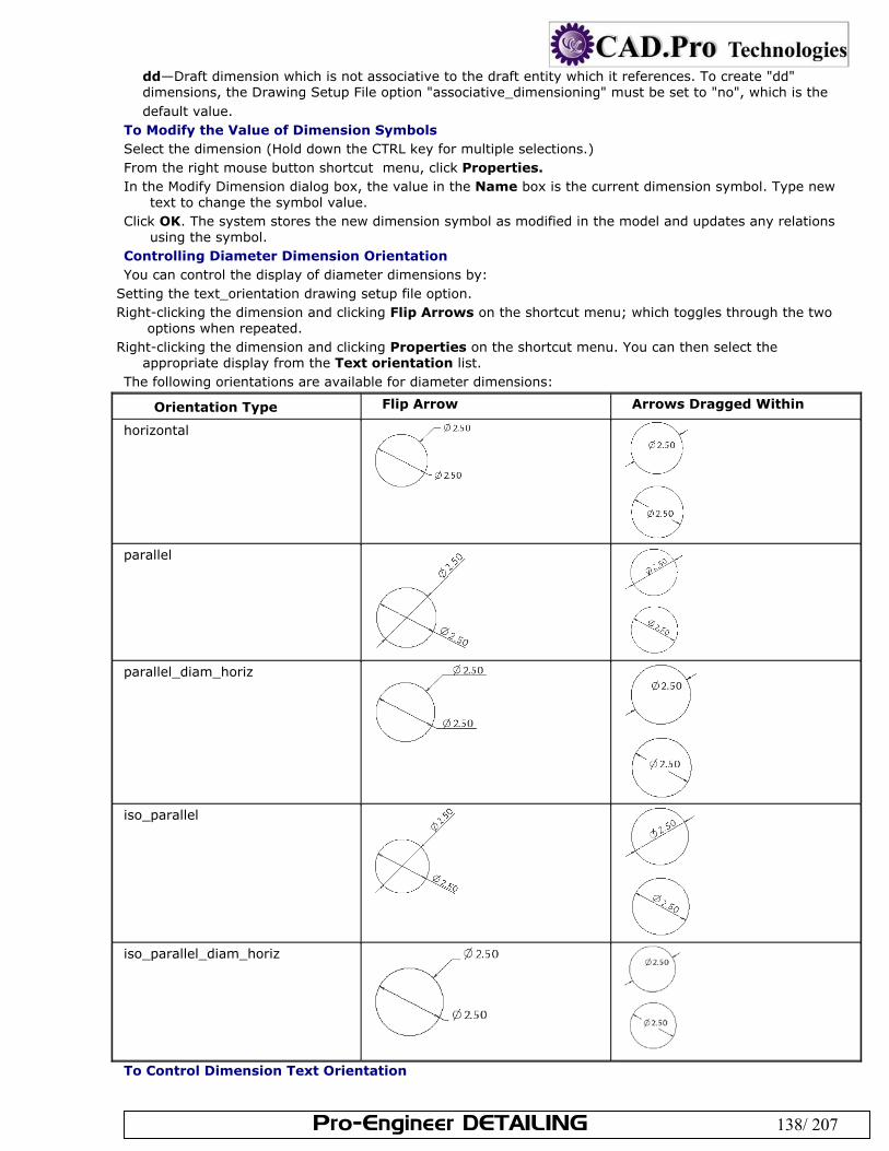
Pro-Engineer DETAILING 138/ 207
dd—Draft dimension which is not associative to the draft entity which it references. To create "dd" dimensions, the Drawing Setup File option "associative_dimensioning" must be set to "no", which is the default value.
To Modify the Value of Dimension Symbols Select the dimension (Hold down the CTRL key for multiple selections.) From the right mouse button shortcut menu, click Properties. In the Modify Dimension dialog box, the value in the Name box is the current dimension symbol. Type new
text to change the symbol value. Click OK. The system stores the new dimension symbol as modified in the model and updates any relations
using the symbol. Controlling Diameter Dimension Orientation You can control the display of diameter dimensions by:
Setting the text_orientation drawing setup file option. Right-clicking the dimension and clicking Flip Arrows on the shortcut menu; which toggles through the two
options when repeated. Right-clicking the dimension and clicking Properties on the shortcut menu. You can then select the
appropriate display from the Text orientation list. The following orientations are available for diameter dimensions:
Orientation Type Flip Arrow Arrows Dragged Within
horizontal
parallel
parallel_diam_horiz
iso_parallel
iso_parallel_diam_horiz
To Control Dimension Text Orientation
Pro-Engineer DETAILING 139/ 207
You can control the positioning of dimension text relative to the leader lines by setting the text_orientation drawing setup file option. Note: The drawing setup file option angdim_text_orientation controls the display of angular dimensions. To Add Text to a Dimension Use this procedure to add prefix or "postfix" text to a dimension.
Select the dimension to modify. Click Edit > Properties. The Modify Dimension dialog box opens. Click the Dimension Text tab. Use the Name, Prefix and Postfix boxes to surround the dimension text. Click OK. The system stores the dimension text with the model, and displays it in either Part mode or Assembly mode when you select the feature the dimension is driving.
To Add Parameters to Dimension Text Use this procedure to add prefix or "postfix" text to a dimension.
Select the dimension to modify. Click Edit > Properties. The Modify Dimension dialog box opens. Click the Dim Text tab. Type the parameter callout in the Prefix or Postfix field. Click OK.
Note: You can place dimensions and parameter text in driven dimensions or associative dimensions owned by the same model; however, you cannot place them in draft dimensions or associative draft dimensions. To Overwrite Dim Value Display with a Text String Use this procedure to replace a driven dimension value with a desired text string. Driven dimensions update with changes made in the 3D-model, but they can not be used to modify the 3D-model from the drawing interface.
Select the dimension to modify. Click Edit > Properties. The Modify Dimension dialog box opens. Click the Dim Text tab. In the text field, replace the symbol @D with @O; then type the desired text. The symbol O represents overwrite; anything you type following this text overwrites the dimension value. The drawing now displays the text string instead of the dimension value.
Note: Dimensions must always have a displayed value. If you do not type text after substituting @O, the system ignores the procedure when modifying driven dimensions and displays the REF text when modifying reference dimensions. To Set The Default Chamfer Dimension Text Display By setting the configuration file option chamfer_45deg_dim_text, you can control the display of chamfer dimension text without affecting the leader. This only affects the text of newly created dimensions. To modify dimensions that you created before changing the setting, you must manually edit the text. Using the drawing setup file option chamfer_45deg_leader_style, you can control the leader type of a chamfer dimension without affecting the text. You must use chamfer_45deg_dim_text and chamfer_45deg_leader_style together to meet the appropriate standard. To control the use of leading or trailing zeros in the dimension value, use the drawing setup file option lead_trail_zeros. To Relate Detail Items and Dimension Text You can directly relate a note, draft geometric tolerance, or symbol to dimension text so that the detail item moves with the dimension when the dimension changes location. To relate an existing detail item to dimension text, Select all items you want to relate to the host object. Click Edit > Group > Relate to Object. Select the "host" dimension. The object or objects are grouped and selected as one. To remove objects from the group, use Edit > Group > Unrelate. Note: When creating a new symbol, note, or free draft geometric tolerance, you can relate it to a dimension when specifying its placement. About Dimensional Tolerances in Pro/DETAIL You can set the tolerance standard as ANSI or ISO, and set the tolerance display on or off. You can drive dimensional tolerances using a set of tolerance tables. The system assigns each model a tolerance standard of either ANSI or ISO.
When you switch from ISO to ANSI, the system assigns the ANSI tolerances based on the nominal dimension’s number of digits and deletes the tolerance table reference.
Pro-Engineer DETAILING 140/ 207
When you switch from ANSI to ISO, a set of tolerance tables drives the ISO-standard tolerances. Loading the System and User-Supplied Tables The configuration file option tolerance_table_dir sets the default directory for a user-defined tolerance table. All Holes and Shafts tables overwrite existing tables when loaded. When loading General and Broken Edge tables, keep in mind the following:
If you load one table that has the same set of class names as the model’s, the system accepts the new table. If you load a table that contains class names that conflict with those already loaded in the system, the system
does not load those class names. If you load two tables with class names that do not conflict with those in the system, but that are different
from them, you overwrite the ones in the system. If the default class of the model does not exist in the new names, you must specify a new class. After you load the new tables, the system assigns the new dimension tolerances and you can regenerate the model. When you regenerate the model the system goes through all of the dimensions and reassigns their tolerances from the tolerance tables. If you modify a dimension tolerance, the system deletes the tolerance table reference for that dimension, and the tolerance value remains the same until you modify it again or reassign the tolerance table. If the regeneration fails, all relevant dimensions acquire the backup tolerance values. However, the new tolerance tables remain. Changing the Tolerance Table Reference All instances in a family share the same set of tolerance tables, the same tolerance standard, and the same class. When changing the tolerance table reference, keep in mind the following:
If you modify model units, but keep all of the dimension values the same, the system updates the tolerance values to reflect the change in the overall model size.
If a Holes or Shafts tolerance table drives a dimension’s tolerances, you cannot show it in a plus-minus symmetric format. The system assumes that the General and Broken Edge tables have symmetric values.
If you place a dimension tolerance in a family table, the system deletes its tolerance table reference. Also, if you switch a model from ANSI to ISO, or vice versa, it preserves the tolerances in the family tables and does not assign table references to those dimensions.
If a dimension value falls outside ranges specified in the table, the system uses the closest range to obtain tolerances (that is, it uses the last range in the system table (2000–4000) to determine tolerances for dimension values of 2000 or greater).
Setting the Tolerance Display To set the tolerance display on and off, use the drawing setup file option tol_display. You can set the default display for dimension tolerances using the configuration file option tol_mode. Using the configuration file option maintain_limit_tol_nominal, you can maintain the nominal value of a dimension regardless of the changes that you make to the tolerance values. If you set it to yes, the system does not modify the Nominal Value of a dimension with a Limits tolerance format when you set the format to Limits or change the value of the upper or lower tolerance. To Set the Tolerance Display for Individual Dimensions Select a dimension. From the right mouse button pop up menu, click Properties. In the Modify Dimension dialog box, select a tolerance format from the Tolerance Mode list. Specify values
in the appropriate fields: For the Limits format, specify values in the Upper Tolerance and Lower Tolerance boxes. For the Nominal and Plus-Minus formats, specify values in the Nominal Value, Upper Tolerance, and Lower Tolerance boxes. For the +-Symmetric and As Is formats, specify a value in the Nominal Value box.
Click OK. When tolerances appear, the system lists the default tolerance values in the lower-right corner of the screen.
To Create an ISO-standard Model in Drawing Mode Click File > Properties. The Menu Manager opens. Click Tolerance Standards > TOL Setup > Standard. Click ISO/DIN or ANSI.
Pro/ENGINEER loads the system and user-supplied tables, and the General table drives all dimensions. Note: The system loads the tolerance tables into the model when you create it as an ISO-standard model or switch the tolerance standard from ANSI to ISO. To create the model as an ISO-standard model, set the configuration file option tolerance_standard to ISO. Since the tables determine how the model regenerates,
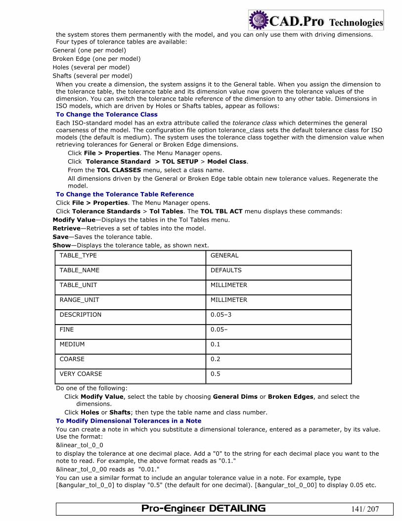
Pro-Engineer DETAILING 141/ 207
the system stores them permanently with the model, and you can only use them with driving dimensions. Four types of tolerance tables are available:
General (one per model) Broken Edge (one per model) Holes (several per model) Shafts (several per model) When you create a dimension, the system assigns it to the General table. When you assign the dimension to the tolerance table, the tolerance table and its dimension value now govern the tolerance values of the dimension. You can switch the tolerance table reference of the dimension to any other table. Dimensions in ISO models, which are driven by Holes or Shafts tables, appear as follows: To Change the Tolerance Class Each ISO-standard model has an extra attribute called the tolerance class which determines the general coarseness of the model. The configuration file option tolerance_class sets the default tolerance class for ISO models (the default is medium). The system uses the tolerance class together with the dimension value when retrieving tolerances for General or Broken Edge dimensions.
Click File > Properties. The Menu Manager opens. Click Tolerance Standard > TOL SETUP > Model Class. From the TOL CLASSES menu, select a class name. All dimensions driven by the General or Broken Edge table obtain new tolerance values. Regenerate the model.
To Change the Tolerance Table Reference Click File > Properties. The Menu Manager opens. Click Tolerance Standards > Tol Tables. The TOL TBL ACT menu displays these commands:
Modify Value—Displays the tables in the Tol Tables menu. Retrieve—Retrieves a set of tables into the model. Save—Saves the tolerance table. Show—Displays the tolerance table, as shown next.
TABLE_TYPE GENERAL
TABLE_NAME DEFAULTS
TABLE_UNIT MILLIMETER
RANGE_UNIT MILLIMETER
DESCRIPTION 0.05–3
FINE 0.05–
MEDIUM 0.1
COARSE 0.2
VERY COARSE 0.5
Do one of the following: Click Modify Value, select the table by choosing General Dims or Broken Edges, and select the
dimensions. Click Holes or Shafts; then type the table name and class number.
To Modify Dimensional Tolerances in a Note You can create a note in which you substitute a dimensional tolerance, entered as a parameter, by its value. Use the format: &linear_tol_0_0 to display the tolerance at one decimal place. Add a "0" to the string for each decimal place you want to the note to read. For example, the above format reads as "0.1." &linear_tol_0_00 reads as "0.01." You can use a similar format to include an angular tolerance value in a note. For example, type [&angular_tol_0_0] to display "0.5" (the default for one decimal). [&angular_tol_0_00] to display 0.05 etc.

Pro-Engineer DETAILING 142/ 207
Because the system includes tolerances in a note as parameters, associativity exists between the tolerance value in a note and a model. When you change tolerance values in a note, the system updates the default tolerance table in Part mode. To modify the tolerance value in a note Select the note. From the right mouse button pop up menu, click Properties. Type a new value for the tolerance. Click OK. Note: Tolerance tables do not affect thread dimensions. Thread dimensions come into the model having the same tolerances with which the system stored them. Example: A Tolerance Table
TABLE_TYPE HOLES
TABLE_NAME A
TABLE_UNIT MICROMETER
RANGE_UNIT MILLIMETER
BASIC SIZE 9 10 11 12 13
—3 295/270 310/270 330/270 370/270 410/270
3 - 6 300/270 318/270 345/270 390/270 450/270
6 - 10 316/280 338/280 370/280 430/280 500/280
10 - 18 333/290 360/290 400/290 470/290 630/300
18 - 30 352/300 384/300 430/300 510/300 700/310
30 - 40 372/310 410/310 470/310 560/310 710/320
40 - 50 382/320 420/320 480/320 570/320 800/340
50 - 65 414/340 460/340 530/340 640/340 820/340
About Basic Dimensions Basic dimensions are theoretically exact dimensions that appear with the measurement value and any associated text enclosed in a feature control frame. If the original dimension has tolerances, the system automatically removes them; you cannot add tolerances to basic dimensions. You can transform existing dimensions into basic dimensions, and set inspection dimensions according to the DIN standard. To Set a Dimension as a Basic Dimension Select the dimension to change. Click Edit > Properties.. In the Display field, click Basic. Click OK. To Set a Dimension as an Inspection Dimension Select the dimension to change. Click Edit > Properties.. In the Display field, click Inspection. The dimension is enclosed in an oval. Click OK. To Modify the Dimensioning Scheme of Feature or Part Change the drawing selection filter to Feature. Select the feature on the drawing you want to redimension and right-click. Click Redefine Feature from the shortcut menu. The feature opens in a new window. If you selected the
base feature, only the section of the base feature and dimension values appear in the separate window. If you selected a later feature on the model, the system rolls back the model and displays it in default orientation in a separate window. The section and dimensions of the feature (if applicable) appear on the model.
Pro-Engineer DETAILING 143/ 207
Add and delete dimensions, or change placement constraints, as necessary. You cannot modify existing dimension values or add or delete features.
Save and close the redimensioned feature. The model regenerates to reflect the changes. Note: If you set the auto_regen_views configuration file option to no, you must choose View > Update > Current Sheet or All Sheets to observe the change in the drawing views. About Modifying Witness Lines When Pro/ENGINEER places a dimension on a model, it leaves a gap between the model and the witness line. The drawing setup file option witness_line_offset controls the actual size of the gap. Sometimes this gap is not visible on a drawing. However, it becomes noticeable when you plot the drawing. To see how the drawing will look when you print it, choose File > Print > Screen. A witness line can have both jogs and breaks. When you add jogs to a witness line that already has breaks, the breaks that were created as simple breaks appear on the first unjogged segment of the witness line. If a witness line has dimension breaks, jogging a witness line relocates a break to a new intersection point. You can edit witness lines in the following ways:
Create parametric or simple breaks in dimension witness lines and in leader lines of notes and symbols. Resize the gap by dragging the end handles. You can simultaneously clip several dimensions that have the
same orientation so that their witness line endpoints all align. Using multiple selection, you can manipulate witness lines in the following ways:
Clip both witness lines of a dimension at the same time. Clip the witness lines of many dimensions at once. When you pick on the witness line of each dimension, the system moves each of the endpoints together.
Erase and resume witness lines. Skew witness lines. Add jogs to and delete them from linear (standard and ordinate) and angular dimension witness lines, note
leaders, and symbol leaders.
Create and modify angular, diametrical, radial, and linear dimensions with and without an elbow. To Shorten a Witness Line
Select the dimension with the witness line that you want to clip. The witness lines are highlighted, with a "handle" at each end. Drag the handles to the desired positions. Note the two way arrow over the handle shows the direction it will move. Middle click to finish.
To Erase a Witness Line You can erase only one witness line of a dimension. If you try to erase the second one after erasing the first one, the system erases the second one and restores the first one. You cannot erase both. Double-click the dimension. The Dimension Properties dialog box opens. Click Erase from Witness line display section. Select the witness line to erase. Note: You cannot erase the witness lines of ordinate dimensions (including ISO-standard ordinate dimensions with a cross-line between the baseline and the dimension). You cannot blank he witness line of a clipped dimension (one that has been clipped as a result of view clipping), and you cannot use Show to restore a witness line that has been automatically erased (clipped due to view clipping). To Restore an Erased Witness Line Select the dimension with the witness line to restore. Click the right mouse button, and select Show Wit Line from the pop up menu. The system redraws the
selected dimension and displays its witness line with a single arrowhead at the leader. To Add a Jog to a Witness Line Click Insert > Jog. Select the dimension value. (This selects the witness lines.) Click the point on a witness line to insert the jog. Move the mouse to place the jog. Click again to release the jog. The command is still active and you can repeat the process to place another
jog. Middle click to exit the command. To Skew Witness Lines Select the dimension with the witness line to edit. Use the cursor to select a handle on the end of a witness line. The cursor changes to an arrow, perpendicular
to the selected witness line. Drag the handle to the desired location. Left click again to place the witness line.
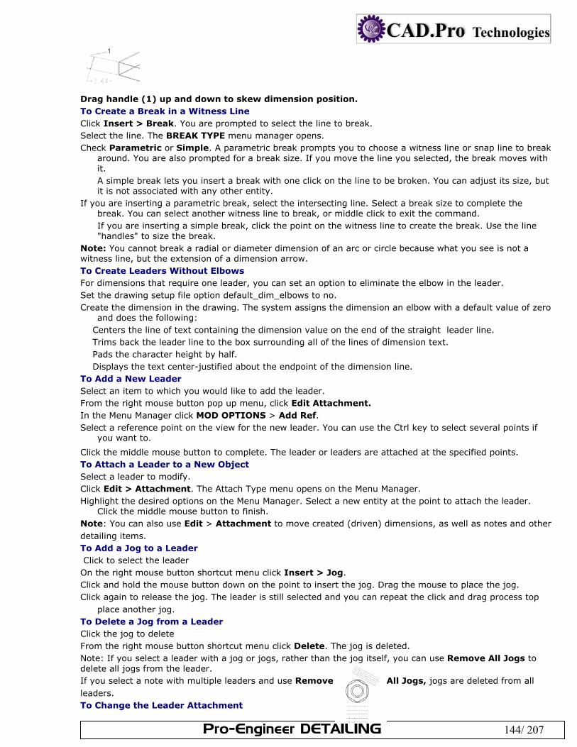
Pro-Engineer DETAILING 144/ 207
Drag handle (1) up and down to skew dimension position. To Create a Break in a Witness Line Click Insert > Break. You are prompted to select the line to break. Select the line. The BREAK TYPE menu manager opens. Check Parametric or Simple. A parametric break prompts you to choose a witness line or snap line to break
around. You are also prompted for a break size. If you move the line you selected, the break moves with it. A simple break lets you insert a break with one click on the line to be broken. You can adjust its size, but it is not associated with any other entity.
If you are inserting a parametric break, select the intersecting line. Select a break size to complete the break. You can select another witness line to break, or middle click to exit the command. If you are inserting a simple break, click the point on the witness line to create the break. Use the line "handles" to size the break.
Note: You cannot break a radial or diameter dimension of an arc or circle because what you see is not a witness line, but the extension of a dimension arrow. To Create Leaders Without Elbows For dimensions that require one leader, you can set an option to eliminate the elbow in the leader. Set the drawing setup file option default_dim_elbows to no. Create the dimension in the drawing. The system assigns the dimension an elbow with a default value of zero
and does the following: Centers the line of text containing the dimension value on the end of the straight leader line. Trims back the leader line to the box surrounding all of the lines of dimension text. Pads the character height by half. Displays the text center-justified about the endpoint of the dimension line.
To Add a New Leader Select an item to which you would like to add the leader. From the right mouse button pop up menu, click Edit Attachment. In the Menu Manager click MOD OPTIONS > Add Ref. Select a reference point on the view for the new leader. You can use the Ctrl key to select several points if
you want to.
Click the middle mouse button to complete. The leader or leaders are attached at the specified points. To Attach a Leader to a New Object Select a leader to modify. Click Edit > Attachment. The Attach Type menu opens on the Menu Manager. Highlight the desired options on the Menu Manager. Select a new entity at the point to attach the leader.
Click the middle mouse button to finish. Note: You can also use Edit > Attachment to move created (driven) dimensions, as well as notes and other detailing items. To Add a Jog to a Leader Click to select the leader On the right mouse button shortcut menu click Insert > Jog. Click and hold the mouse button down on the point to insert the jog. Drag the mouse to place the jog. Click again to release the jog. The leader is still selected and you can repeat the click and drag process top
place another jog. To Delete a Jog from a Leader Click the jog to delete From the right mouse button shortcut menu click Delete. The jog is deleted. Note: If you select a leader with a jog or jogs, rather than the jog itself, you can use Remove All Jogs to delete all jogs from the leader. If you select a note with multiple leaders and use Remove All Jogs, jogs are deleted from all leaders. To Change the Leader Attachment
Pro-Engineer DETAILING 145/ 207
Select the note. Click Edit > Attachment from the right mouse button shortcut menu. The Attach Type menu opens on the
menu manager.
Use the menu manager to change the attachment type or style. To Change the Arrowhead Style Click Format > Arrow Style. The Arrow Style menu opens on the menu manager. Highlight the arrowhead style you want to apply in the menu manager, then click an arrowhead in the
drawing. You can hold down the Ctrl key to select multiple arrowheads.
Click OK in the confirmation box. The arrowhead styles are changed. To Move Leader Attachment in a Multi Line Note
Double click the note. The Enter Text dialog box opens. Type "@o" (the letter o) at the beginning of the line of text you want the leader to attach to. Do not leave a space between the symbol and the text.
Click OK. The leader is attached at the designated line. About Managing Drawing Details with Snap Lines Snap lines are entities in your drawings that help locate dimensions and detailing items, including notes, geometric tolerances, symbols, and surface finishes. After you place an item on a snap line, the item moves with the line. For example, if you place several dimensions on a snap line you can simultaneously reposition all the dimensions by dragging the snap line—while maintaining the alignment of the dimensions. You can offset snap lines from either drawing view borders, datum planes, drawing geometry, or existing snap lines. Snap lines follow the drawing view or object they are attached to. For example, if you attach a snap line to a view border and then rotate the view by 30 degrees, the snap lines also rotate. If you delete the view borders, datum planes, drawing geometry, or existing snap lines that a snap line is attached to, the snap lines still remain in the drawing. Snap lines are positioned relative to the selected view border, datum plane, or drawing object. The default snap line length is primarily controlled by the selected object, which means that changes to the selected object will correspondingly change the snap line length as well. After the snap lines have been created you can independently change the snap line length by dragging the handles on the end of the snap line.
Moving a snap line attached to a view border or drawing object causes all other related snap lines to move accordingly.
The ladder effect controls the movement of snap lines. For example, if you have 5 snap lines and snap line 1 is attached to a view border or drawing object, moving snap line 1 will cause snap lines 2 through 5 to move. Moving snap line 2 would cause snap lines 3 through 5 to move.
Note: Snap lines are not a graphical part of the drawing, so they do not plot. The drawing object filter can make selecting snap lines. To Create a Snap Line Snap lines enable you to locate dimensions and detailing items in your drawings. After you place an item on a snap line, the item moves with the line. Click Insert > Snap Line. The CR SN LINE menu appears on the Menu Manager. Define how you want to offset the snap line; from an object or view:
Att View—Offset snap lines from a drawing view borders. Att Geom/Snap—Offset snap lines from a drawing object, including geometry, datum plane, and other snap
lines. Depending on how you defined the snap line offset, select the appropriate view borders or drawing objects to
offset the snap line from. If you select a non-straight drawing object, keep in mind that a straight snap line will be created tangent to the point you select. The selected items highlight.
Click the middle mouse button to confirm your selection. You are prompted for an offset distance. If you are offsetting the snap line from a drawing object, a direction arrow appears, indicating where the snap line will be created.
Type the offset distance for the first snap line. A negative value positions the snap line in the opposite direction of the direction arrow. Click the middle mouse button to confirm the distance. If you are creating multiple snap lines from the same reference, type the number of snap lines to create and then specify the space between the lines.
Click the middle mouse button to confirm the snap line creation. The snap line is attached to the specified view borders or drawing objects. To leave the snap line creation process, click the middle mouse button or click Done/Return.
Pro-Engineer DETAILING 146/ 207
Note: You can change the snap line offset distances by double-clicking on the snap line. You are prompted to type
the new offset value. You can delete a snap line by right-clicking it and selecting Delete from the shortcut menu. You could also
select the snap line and press DEL or click Edit > Delete. To Place Items on Snap Lines You can add dimensions and detailing items to snap lines. Any items that are snapped to the line will move with the line. Select the dimension or detailing item you wish to place on a snap line. The item is highlighted. Drag the dimension or detailing item over the desired snap line. If the item can be snapped, the snap line
turns purple. After you release the mouse button, the item is snapped to the line. Note: Under Default Actions, select Snap to Snap Lines. By default, the system selects both commands. If snap lines do not appear or you have unchecked the Snap to Snap Lines checkbox, the items that are already snapped to a snap line continue to move with their snap lines. To Modify Snap Line Attachment or Spacing Select a snap line, and then right-click the line to display the shortcut menu. Click Edit Attachment. The MOD SNAP ATT menu opens in the Menu Manager. Click one of these
commands: Keep Position—Maintain the position of the snap line. Change Orient—Reroute the snap line, changing its orientation by assigning the offset of the existing
reference to the new reference. Att View—Reroute the snap line attachment to a view border. Att Geom/Snap—Reroute the snap line attachment to other geometry or another snap line.
Specify a new reference. The snap line attachment changes. Note: You can manipulate snap lines in several other ways:
To remove a snap line, select the line and then click Edit > Delete. Once you delete a snap line, any items located on it are free.
To change the position of a snap line, select the line and then drag it to its new position. The system updates all items located on the moved snap line after you choose a new location.
To control the length (position of the endpoints) of a snap line, select the line and drag an endpoint (handle). To change the spacing of a snap line, select the line, right-click on the line, and then choose Properties from
the shortcut menu. Enter a new spacing value and then press ENTER. The system updates all items located on the moved snap line after you choose a new location. You can also
To Control the Display of Snap Lines By default, snap lines are visible in drawings. However, they are only used to help locate your dimensions and drawing detailing, so they do not plot with the drawing. Click Tools > Environment. The Environment dialog box opens. Under Display, select Snap Lines. The snap lines are visible in the drawing. About Drawing Tables A drawing table is a grid of rows and columns in which you can enter text. The text in a drawing table has complete text functionality; you can modify it by double clicking the cell and entering the text in a dialog box. You can enter dimension symbols and drawing labels as well, and the system updates them as you modify the model or drawing. You can include a drawing table in drawing formats, drawings, and layouts. You can modify the line font, color, and width of a table grid the same way you would modify geometry. Using Pro/Report with Tables The Pro/Report license lets you designate certain cells as "repeat regions" that automatically populate with design data that you specify through special report parameters in the cell. If you define these regions in a report file, (.rep) they are read-only. If you define them in a drawing however, you can edit values shown in the drawing table and pass the edits back to the associated parts. See About Creating Reports for more information on this subject. Tip: Selecting Table Cells You can select a table using pre-highlighting. When you move the pointer to any corner of the table, the entire table is pre-highlighted. You can then click to select the table. To select a row or column using pre-highlighting move the pointer over an outer cell border. The row or column is pre-highlighted. Click to select. To Create a Drawing Table Click Table > Insert > Table. Locate the table by clicking on the drawing. A scale of numbers appears.
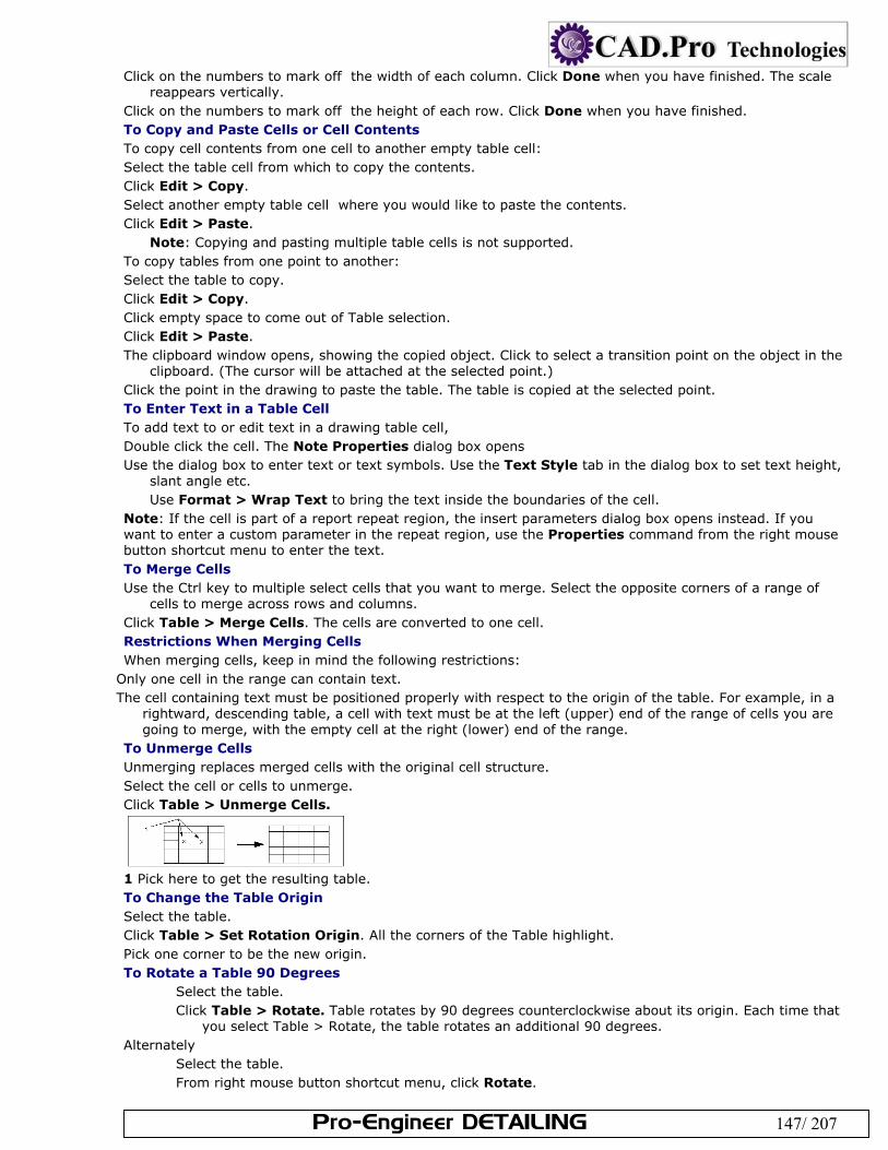
Pro-Engineer DETAILING 147/ 207
Click on the numbers to mark off the width of each column. Click Done when you have finished. The scale reappears vertically.
Click on the numbers to mark off the height of each row. Click Done when you have finished. To Copy and Paste Cells or Cell Contents To copy cell contents from one cell to another empty table cell: Select the table cell from which to copy the contents. Click Edit > Copy. Select another empty table cell where you would like to paste the contents. Click Edit > Paste.
Note: Copying and pasting multiple table cells is not supported. To copy tables from one point to another: Select the table to copy. Click Edit > Copy. Click empty space to come out of Table selection. Click Edit > Paste. The clipboard window opens, showing the copied object. Click to select a transition point on the object in the
clipboard. (The cursor will be attached at the selected point.) Click the point in the drawing to paste the table. The table is copied at the selected point. To Enter Text in a Table Cell To add text to or edit text in a drawing table cell, Double click the cell. The Note Properties dialog box opens Use the dialog box to enter text or text symbols. Use the Text Style tab in the dialog box to set text height,
slant angle etc. Use Format > Wrap Text to bring the text inside the boundaries of the cell.
Note: If the cell is part of a report repeat region, the insert parameters dialog box opens instead. If you want to enter a custom parameter in the repeat region, use the Properties command from the right mouse button shortcut menu to enter the text. To Merge Cells Use the Ctrl key to multiple select cells that you want to merge. Select the opposite corners of a range of
cells to merge across rows and columns. Click Table > Merge Cells. The cells are converted to one cell. Restrictions When Merging Cells When merging cells, keep in mind the following restrictions:
Only one cell in the range can contain text. The cell containing text must be positioned properly with respect to the origin of the table. For example, in a
rightward, descending table, a cell with text must be at the left (upper) end of the range of cells you are going to merge, with the empty cell at the right (lower) end of the range.
To Unmerge Cells Unmerging replaces merged cells with the original cell structure. Select the cell or cells to unmerge. Click Table > Unmerge Cells.
1 Pick here to get the resulting table. To Change the Table Origin Select the table. Click Table > Set Rotation Origin. All the corners of the Table highlight. Pick one corner to be the new origin. To Rotate a Table 90 Degrees
Select the table. Click Table > Rotate. Table rotates by 90 degrees counterclockwise about its origin. Each time that
you select Table > Rotate, the table rotates an additional 90 degrees. Alternately
Select the table. From right mouse button shortcut menu, click Rotate.
Pro-Engineer DETAILING 148/ 207
To Blank or Display Cell Borders You can hide selected cell lines within a table. Select the entire table. Click Table > Line Display. In the Menu Manager, select an option, then select lines on the table:
Blank—Blanks the selected line segment. Unblank—Redisplays the selected line segment in the table. Unblank All—Redisplays all blanked lines in the table.
To Insert or Remove Rows or Columns To Insert a Row or Column Click Table > Insert > Row or Column. Do one of the following:
To insert a row, select a horizontal line in the table. A new row is placed between the two rows that border the selected line.
To insert a column, select a vertical line in the table. A new column is placed between the two columns that border the selected line.
To Remove a Row or Column Click a cell in the column or row you want to remove. Click Table > Select > Row or Column. The row or column is selected. Press Del. The column or row is deleted. (You can use Undelete on the right mouse button shortcut menu to
abort the deletion, or click open space on the drawing to confirm it.) To Resize Rows and Columns You can set row height in units, or a number of characters as measurements of height. Select the rows or columns to reset. Click Table > Height and Width. Use the dialog box to set the new dimensions for the selected rows or columns. To Word Wrap Table Text Select the table cell containing the text From the right mouse button pop up menu, click Wrap Text. The text wraps to the column width. Note: If you need to extend the row height, use the Height and Width command on the right mouse button shortcut menu. To Justify Text Select a table or a row or column from the table. Click Format > Text Style. The Properties dialog box opens. Click the Text Style tab. Select the justification style from the Note / Dimension field. Click OK to finish. To Move a Table Click to select the table. Move the cursor over one of the handles on the outline, until the cursor changes to a
four-way arrow. Hold the left mouse button down, and drag the table to where you want it. Release the left mouse button to place the table.
Alternately, you can use Edit > Move Special to enter X and Y coordinates for the target location. Note: To move a table to another sheet, select the table and use Edit > Move Item to Sheet. To Delete a Table Select the table to delete. Click Edit > Delete. To Save a Table Select the table or a cell of a table to save. Click Table > Save Table > As Table File or As Text File Type a name for the table. The system saves it to a file in your current directory with a .tbl extension. It
gives the filename a unique version number to prevent overwriting tables with the same name. To Save a Table as Text Select the table or a cell of a table to save. Click Table> Save Table > As Text File.
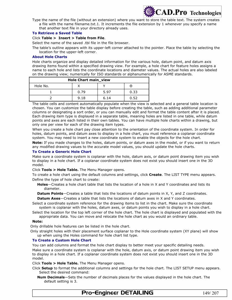
Pro-Engineer DETAILING 149/ 207
Type the name of the file (without an extension) where you want to store the table text. The system creates a file with the name filename.txt.1. It increments the file extension by 1 whenever you specify a name that another text file in your directory already uses.
To Retrieve a Saved Table Click Table > Insert > Table from File. Select the name of the saved .tbl file in the file browser. The table’s outline appears with its upper-left corner attached to the pointer. Place the table by selecting the
location for the upper-left corner. About Hole Charts Hole charts organize and display detailed information for the various hole, datum point, and datum axis drawing items found within a specified drawing view. For example, a hole chart for feature holes assigns a name to each hole and lists the coordinate locations and diameter values. The actual holes are also labeled on the drawing view; numerically for ISO standards or alphanumerically for ASME standards.
Hole Chart main_view
Hole No. X Y Θ
1 0.79 5.97 0.33
2 9.18 6.14 0.52
The table cells and content automatically populate when the view is selected and a general table location is chosen. You can customize the table display before creating the table, such as adding additional parameter columns or designating a sort order, or you can manually edit and format the table content after it is placed. Each drawing item type is displayed in a separate table, meaning holes are listed in one table, while datum points and axes are each listed in their own tables. You can have multiple hole charts within a drawing, but only one per view for each of the drawing item types. When you create a hole chart pay close attention to the orientation of the coordinate system. In order for holes, datum points, and datum axes to display in a hole chart, you must reference a coplanar coordinate system. You may need to insert a new coordinate system to enable the objects for the hole chart. Note: If you made changes to the holes, datum points, or datum axes in the model, or if you want to return any modified drawing values to the accurate model values, you should update the hole charts. To Create a Generic Hole Chart Make sure a coordinate system is coplanar with the hole, datum axis, or datum point drawing item you wish to display in a hole chart. If a coplanar coordinate system does not exist you should insert one in the 3D model. Click Tools > Hole Table. The Menu Manager opens. To create a hole chart using the default columns and settings, click Create. The LIST TYPE menu appears. Define the type of hole chart to create:
Holes—Creates a hole chart table that lists the location of a hole in X and Y coordinates and lists its diameter.
Datum Points—Creates a table that lists the locations of datum points in X, Y, and Z coordinates. Datum Axes—Creates a table that lists the locations of datum axes in X and Y coordinates.
Select a coordinate system reference for the drawing items to list in the chart. Make sure the coordinate system is coplanar with the holes, datum axes, or datum points you wish to display in a hole chart.
Select the location for the top left corner of the hole chart. The hole chart is displayed and populated with the appropriate data. You can move and relocate the hole chart as you would an ordinary table.
Note: Only drillable hole features can be listed in the hole chart. Only straight holes with their placement surface coplanar to the Hole coordinate system (XY plane) will show
up when using the Holes command for hole chart list type. To Create a Custom Hole Chart You can add columns and format the hole chart display to better meet your specific detailing needs. Make sure a coordinate system is coplanar with the hole, datum axis, or datum point drawing item you wish to display in a hole chart. If a coplanar coordinate system does not exist you should insert one in the 3D model. Click Tools > Hole Table. The Menu Manager opens. Click Setup to format the additional columns and settings for the hole chart. The LIST SETUP menu appears.
Select the desired command: Num Decimals—Sets the number of decimals places for the values displayed in the hole chart. The
default setting is 3.
Pro-Engineer DETAILING 150/ 207
Param Column—Defines additional columns for the hole chart. When you create a hole chart the default column format includes a table heading and a name column, as well as: Holes—X and Y coordinate columns and a diameter column. Datum points—X, Y, and Z coordinate columns. Datum axes—X and Y coordinate columns.
Note: When adding a new parameter column, the parameter type must be a feature parameter. You can view a listing of all the added columns by clicking List.
Label Size—Defines the size of the text used to label the holes on the drawing view. The default size is -1, however, you can type a new value greater than zero.
Max Rows—Defines the maximum number of rows in a hole chart or table. Hole Naming—Defines the method of naming holes. The default is set to the ASME standard
(Alphanumeric), however, the ISO standard (Numeric) is available. Sort Setup—Modifies the protocol for sorting entries in the hole chart or table. By default, hole charts are
sorted by the name column. To create the hole chart, click Create. The LIST TYPE menu appears. Define the type of hole chart to create:
Holes—Creates a hole chart table that lists the location of a hole in X and Y coordinates and lists its diameter.
Datum Points—Creates a table that lists the locations of datum points in X, Y, and Z coordinates. Datum Axes—Creates a table that lists the locations of datum axes in X and Y coordinates.
Select a coordinate system reference for the drawing items to list in the chart. Make sure the coordinate system is coplanar with the holes, datum axes, or datum points you wish to display in a hole chart.
Select the location for the top left corner of the hole chart. The hole chart is displayed and populated with the appropriate data. You can move and relocate the hole chart as you would an ordinary table.
Note: Only drillable hole features can be listed in the hole chart. Only straight holes with their placement surface coplanar to the Hole coordinate system (XY plane) will show
up when using the Holes command for hole chart list type. To Update a Hole Chart If you made changes to the holes, datum points, or datum axes in the model, or if you want to return any modified hole chart values to the accurate model values, you should update the hole charts. Click Tools > Hole Table. The HOLE TABLE menu appears in the menu manager. Click Update. The hole charts update with the most recent model information. Note: You can modify the hole chart table cells as you would a normal table—double click the cell or right-click the cell and click Properties. Using the Report File Type You can create a new file dedicated to report information using the file type Report (.rpt). Report mode menus are abbreviated versions of the Drawing mode menus. In a Report file, you can display data for an associated 3D model in table form just as it is in drawing mode. The system updates the information when you edit the model. This mode provides all of the forward-associative abilities that Drawing mode offers. The only associative difference is that you cannot modify the model from a report file as you can from a drawing file. About Creating Reports in Drawing Files In Drawing mode, you can create dynamic, customized table reports. By defining repeat regions across table cells, you can add model data to a report which updates as the model changes, adding or subtracting rows or columns automatically as necessary. You can also use the following techniques to manage the data that appears in a report:
Add filters to eliminate specific types of data from appearing in reports, drawing tables, or layout tables. Search recursive or top-level assembly data for display. List duplicate occurrences of model data individually or as a group in a report, drawing table, or layout table. Directly link assembly component balloons to a customized BOM and automatically update them when you
make assembly modifications. You can generate several kinds of output using the report functions, such as family tables, associative reports, and graphical wirelists. A common example of a report is a customized Bill of Materials (BOM), such as the one shown in the next figure. Report with Assembly Views
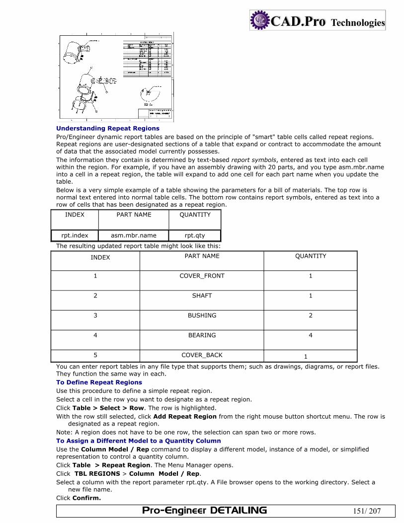
Pro-Engineer DETAILING 151/ 207
Understanding Repeat Regions Pro/Engineer dynamic report tables are based on the principle of "smart" table cells called repeat regions. Repeat regions are user-designated sections of a table that expand or contract to accommodate the amount of data that the associated model currently possesses. The information they contain is determined by text-based report symbols, entered as text into each cell within the region. For example, if you have an assembly drawing with 20 parts, and you type asm.mbr.name into a cell in a repeat region, the table will expand to add one cell for each part name when you update the table. Below is a very simple example of a table showing the parameters for a bill of materials. The top row is normal text entered into normal table cells. The bottom row contains report symbols, entered as text into a row of cells that has been designated as a repeat region.
INDEX PART NAME QUANTITY
rpt.index asm.mbr.name rpt.qty
The resulting updated report table might look like this:
INDEX PART NAME QUANTITY
1 COVER_FRONT 1
2 SHAFT 1
3 BUSHING 2
4 BEARING 4
5 COVER_BACK 1
You can enter report tables in any file type that supports them; such as drawings, diagrams, or report files. They function the same way in each. To Define Repeat Regions Use this procedure to define a simple repeat region. Select a cell in the row you want to designate as a repeat region. Click Table > Select > Row. The row is highlighted. With the row still selected, click Add Repeat Region from the right mouse button shortcut menu. The row is
designated as a repeat region. Note: A region does not have to be one row, the selection can span two or more rows. To Assign a Different Model to a Quantity Column Use the Column Model / Rep command to display a different model, instance of a model, or simplified representation to control a quantity column. Click Table > Repeat Region. The Menu Manager opens. Click TBL REGIONS > Column Model / Rep. Select a column with the report parameter rpt.qty. A File browser opens to the working directory. Select a
new file name. Click Confirm.
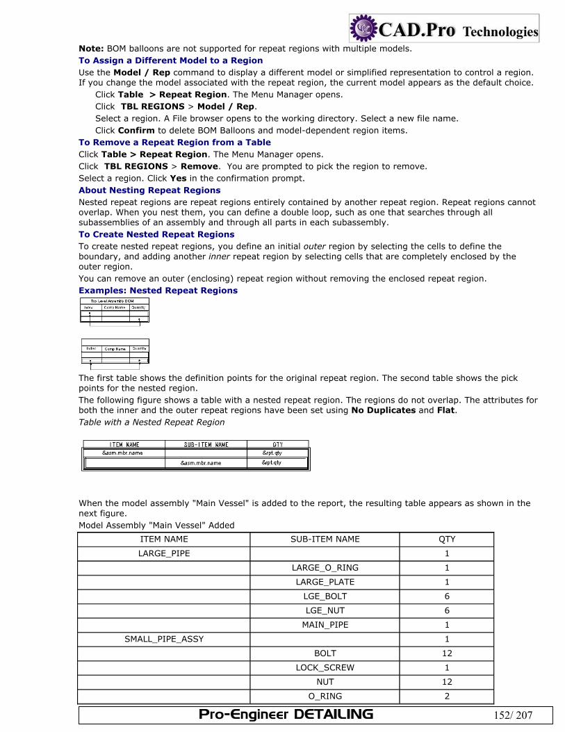
Pro-Engineer DETAILING 152/ 207
Note: BOM balloons are not supported for repeat regions with multiple models. To Assign a Different Model to a Region Use the Model / Rep command to display a different model or simplified representation to control a region. If you change the model associated with the repeat region, the current model appears as the default choice.
Click Table > Repeat Region. The Menu Manager opens. Click TBL REGIONS > Model / Rep. Select a region. A File browser opens to the working directory. Select a new file name. Click Confirm to delete BOM Balloons and model-dependent region items.
To Remove a Repeat Region from a Table Click Table > Repeat Region. The Menu Manager opens. Click TBL REGIONS > Remove. You are prompted to pick the region to remove. Select a region. Click Yes in the confirmation prompt. About Nesting Repeat Regions Nested repeat regions are repeat regions entirely contained by another repeat region. Repeat regions cannot overlap. When you nest them, you can define a double loop, such as one that searches through all subassemblies of an assembly and through all parts in each subassembly. To Create Nested Repeat Regions To create nested repeat regions, you define an initial outer region by selecting the cells to define the boundary, and adding another inner repeat region by selecting cells that are completely enclosed by the outer region. You can remove an outer (enclosing) repeat region without removing the enclosed repeat region. Examples: Nested Repeat Regions
The first table shows the definition points for the original repeat region. The second table shows the pick points for the nested region. The following figure shows a table with a nested repeat region. The regions do not overlap. The attributes for both the inner and the outer repeat regions have been set using No Duplicates and Flat. Table with a Nested Repeat Region
When the model assembly "Main Vessel" is added to the report, the resulting table appears as shown in the next figure. Model Assembly "Main Vessel" Added
ITEM NAME SUB-ITEM NAME QTY
LARGE_PIPE 1
LARGE_O_RING 1
LARGE_PLATE 1
LGE_BOLT 6
LGE_NUT 6
MAIN_PIPE 1
SMALL_PIPE_ASSY 1
BOLT 12
LOCK_SCREW 1
NUT 12
O_RING 2
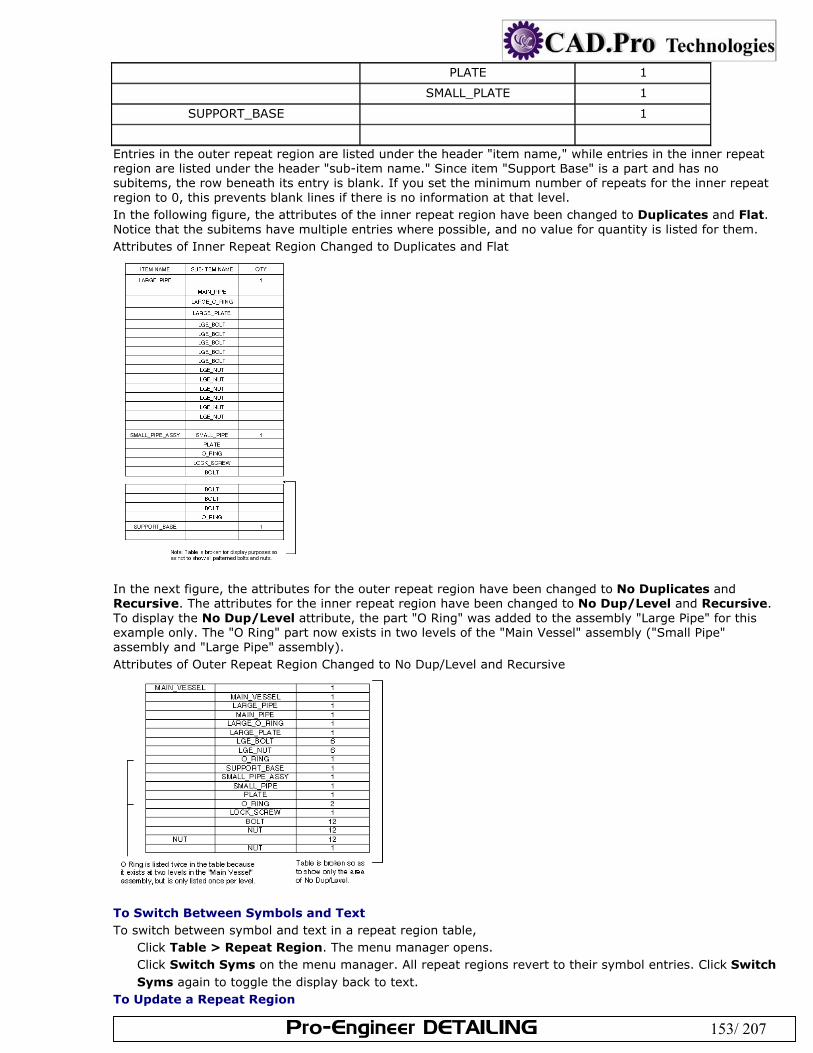
Pro-Engineer DETAILING 153/ 207
PLATE 1
SMALL_PLATE 1
SUPPORT_BASE 1
Entries in the outer repeat region are listed under the header "item name," while entries in the inner repeat region are listed under the header "sub-item name." Since item "Support Base" is a part and has no subitems, the row beneath its entry is blank. If you set the minimum number of repeats for the inner repeat region to 0, this prevents blank lines if there is no information at that level. In the following figure, the attributes of the inner repeat region have been changed to Duplicates and Flat. Notice that the subitems have multiple entries where possible, and no value for quantity is listed for them. Attributes of Inner Repeat Region Changed to Duplicates and Flat
In the next figure, the attributes for the outer repeat region have been changed to No Duplicates and Recursive. The attributes for the inner repeat region have been changed to No Dup/Level and Recursive. To display the No Dup/Level attribute, the part "O Ring" was added to the assembly "Large Pipe" for this example only. The "O Ring" part now exists in two levels of the "Main Vessel" assembly ("Small Pipe" assembly and "Large Pipe" assembly). Attributes of Outer Repeat Region Changed to No Dup/Level and Recursive
To Switch Between Symbols and Text To switch between symbol and text in a repeat region table,
Click Table > Repeat Region. The menu manager opens. Click Switch Syms on the menu manager. All repeat regions revert to their symbol entries. Click Switch Syms again to toggle the display back to text.
To Update a Repeat Region
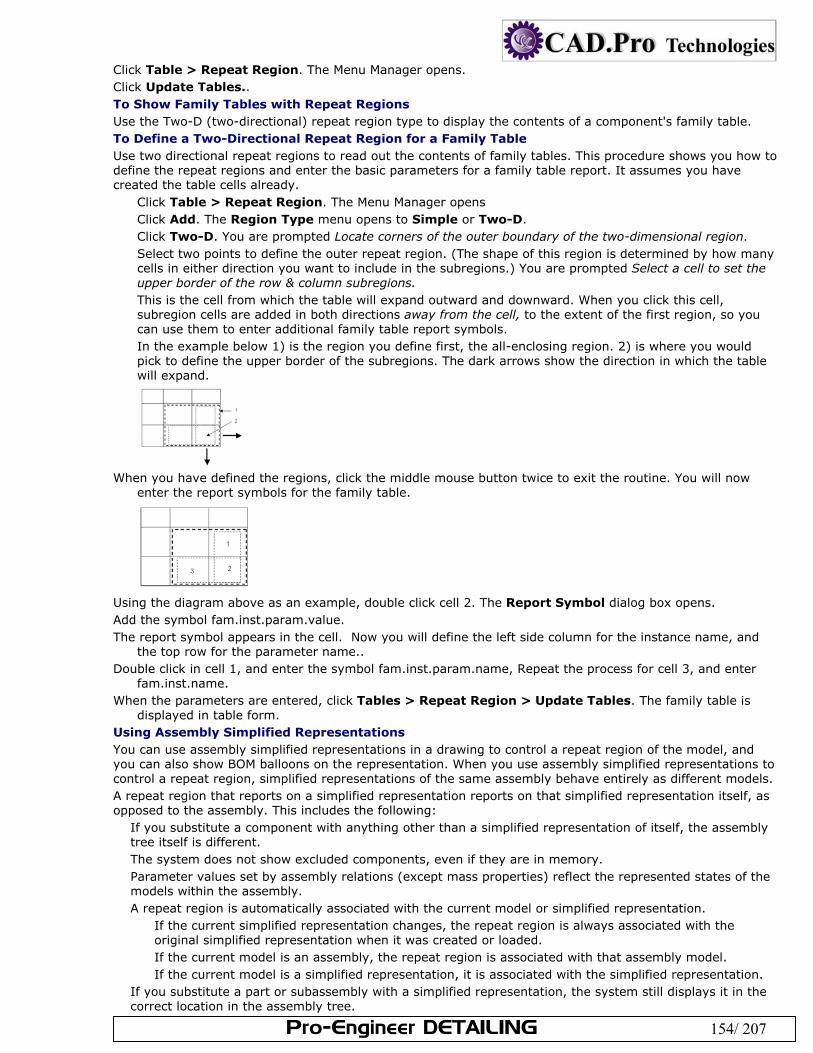
Pro-Engineer DETAILING 154/ 207
Click Table > Repeat Region. The Menu Manager opens. Click Update Tables.. To Show Family Tables with Repeat Regions Use the Two-D (two-directional) repeat region type to display the contents of a component's family table. To Define a Two-Directional Repeat Region for a Family Table Use two directional repeat regions to read out the contents of family tables. This procedure shows you how to define the repeat regions and enter the basic parameters for a family table report. It assumes you have created the table cells already.
Click Table > Repeat Region. The Menu Manager opens Click Add. The Region Type menu opens to Simple or Two-D. Click Two-D. You are prompted Locate corners of the outer boundary of the two-dimensional region. Select two points to define the outer repeat region. (The shape of this region is determined by how many cells in either direction you want to include in the subregions.) You are prompted Select a cell to set the upper border of the row & column subregions. This is the cell from which the table will expand outward and downward. When you click this cell, subregion cells are added in both directions away from the cell, to the extent of the first region, so you can use them to enter additional family table report symbols. In the example below 1) is the region you define first, the all-enclosing region. 2) is where you would pick to define the upper border of the subregions. The dark arrows show the direction in which the table will expand.
When you have defined the regions, click the middle mouse button twice to exit the routine. You will now
enter the report symbols for the family table.
Using the diagram above as an example, double click cell 2. The Report Symbol dialog box opens. Add the symbol fam.inst.param.value. The report symbol appears in the cell. Now you will define the left side column for the instance name, and
the top row for the parameter name.. Double click in cell 1, and enter the symbol fam.inst.param.name, Repeat the process for cell 3, and enter
fam.inst.name. When the parameters are entered, click Tables > Repeat Region > Update Tables. The family table is
displayed in table form. Using Assembly Simplified Representations You can use assembly simplified representations in a drawing to control a repeat region of the model, and you can also show BOM balloons on the representation. When you use assembly simplified representations to control a repeat region, simplified representations of the same assembly behave entirely as different models. A repeat region that reports on a simplified representation reports on that simplified representation itself, as opposed to the assembly. This includes the following:
If you substitute a component with anything other than a simplified representation of itself, the assembly tree itself is different. The system does not show excluded components, even if they are in memory. Parameter values set by assembly relations (except mass properties) reflect the represented states of the models within the assembly. A repeat region is automatically associated with the current model or simplified representation.
If the current simplified representation changes, the repeat region is always associated with the original simplified representation when it was created or loaded. If the current model is an assembly, the repeat region is associated with that assembly model. If the current model is a simplified representation, it is associated with the simplified representation.
If you substitute a part or subassembly with a simplified representation, the system still displays it in the correct location in the assembly tree.
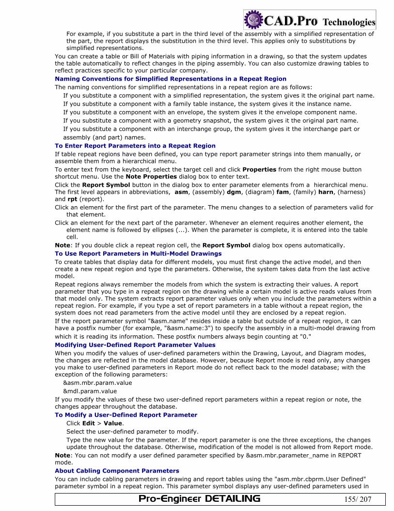
Pro-Engineer DETAILING 155/ 207
For example, if you substitute a part in the third level of the assembly with a simplified representation of the part, the report displays the substitution in the third level. This applies only to substitutions by simplified representations.
You can create a table or Bill of Materials with piping information in a drawing, so that the system updates the table automatically to reflect changes in the piping assembly. You can also customize drawing tables to reflect practices specific to your particular company. Naming Conventions for Simplified Representations in a Repeat Region The naming conventions for simplified representations in a repeat region are as follows:
If you substitute a component with a simplified representation, the system gives it the original part name. If you substitute a component with a family table instance, the system gives it the instance name. If you substitute a component with an envelope, the system gives it the envelope component name. If you substitute a component with a geometry snapshot, the system gives it the original part name. If you substitute a component with an interchange group, the system gives it the interchange part or assembly (and part) names.
To Enter Report Parameters into a Repeat Region If table repeat regions have been defined, you can type report parameter strings into them manually, or assemble them from a hierarchical menu. To enter text from the keyboard, select the target cell and click Properties from the right mouse button shortcut menu. Use the Note Properties dialog box to enter text. Click the Report Symbol button in the dialog box to enter parameter elements from a hierarchical menu. The first level appears in abbreviations, asm, (assembly) dgm, (diagram) fam, (family) harn, (harness) and rpt (report). Click an element for the first part of the parameter. The menu changes to a selection of parameters valid for
that element. Click an element for the next part of the parameter. Whenever an element requires another element, the
element name is followed by ellipses (...). When the parameter is complete, it is entered into the table cell.
Note: If you double click a repeat region cell, the Report Symbol dialog box opens automatically. To Use Report Parameters in Multi-Model Drawings To create tables that display data for different models, you must first change the active model, and then create a new repeat region and type the parameters. Otherwise, the system takes data from the last active model. Repeat regions always remember the models from which the system is extracting their values. A report parameter that you type in a repeat region on the drawing while a certain model is active reads values from that model only. The system extracts report parameter values only when you include the parameters within a repeat region. For example, if you type a set of report parameters in a table without a repeat region, the system does not read parameters from the active model until they are enclosed by a repeat region. If the report parameter symbol "&asm.name" resides inside a table but outside of a repeat region, it can have a postfix number (for example, "&asm.name:3") to specify the assembly in a multi-model drawing from which it is reading its information. These postfix numbers always begin counting at "0." Modifying User-Defined Report Parameter Values When you modify the values of user-defined parameters within the Drawing, Layout, and Diagram modes, the changes are reflected in the model database. However, because Report mode is read only, any changes you make to user-defined parameters in Report mode do not reflect back to the model database; with the exception of the following parameters:
&asm.mbr.param.value &mdl.param.value
If you modify the values of these two user-defined report parameters within a repeat region or note, the changes appear throughout the database. To Modify a User-Defined Report Parameter
Click Edit > Value. Select the user-defined parameter to modify. Type the new value for the parameter. If the report parameter is one the three exceptions, the changes update throughout the database. Otherwise, modification of the model is not allowed from Report mode.
Note: You can not modify a user defined parameter specified by &asm.mbr.parameter_name in REPORT mode. About Cabling Component Parameters You can include cabling parameters in drawing and report tables using the "asm.mbr.cbprm.User Defined" parameter symbol in a repeat region. This parameter symbol displays any user-defined parameters used in
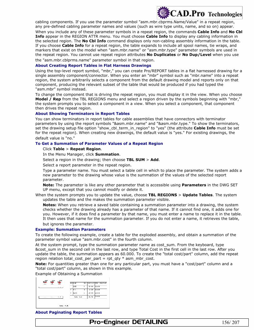
Pro-Engineer DETAILING 156/ 207
cabling components. If you use the parameter symbol "asm.mbr.cbprms.Name/Value" in a repeat region, any pre-defined cabling parameter names and values (such as wire type units, name, and so on) appear. When you include any of these parameter symbols in a repeat region, the commands Cable Info and No Cbl Info appear in the REGION ATTR menu. You must choose Cable Info to display any cabling information in the selected region. The No Cbl Info command displays only non-cabling assembly information in the table. If you choose Cable Info for a repeat region, the table expands to include all spool names, tie wraps, and markers that exist on the model when "asm.mbr.name" or "asm.mbr.type" parameter symbols are used in the repeat region. You cannot use repeat region attributes No Duplicates or No Dup/Level when you use the "asm.mbr.cblprms.name" parameter symbol in that region. About Creating Report Tables in Flat Harness Drawings Using the top-level report symbol, "mbr," you can create Pro/REPORT tables in a flat harnessed drawing for a single assembly component/connector. When you enter an "mbr" symbol such as "mbr.name" into a repeat region, the system arbitrarily selects a component from the default drawing model and reports only on that component, producing the relevant subset of the table that would be produced if you had typed the "asm.mbr" symbol instead. To change the component that is driving the repeat region, you must display it in the view. When you choose Model / Rep from the TBL REGIONS menu and select a region driven by the symbols beginning with "mbr," the system prompts you to select a component in a view. When you select a component, that component then drives the repeat region. About Showing Terminators in Report Tables You can show terminators in report tables for cable assemblies that have connectors with terminator parameters by using the report symbols "&asm.mbr.name" and "&asm.mbr.type." To show the terminators, set the drawing setup file option "show_cbl_term_in_region" to "yes" (the attribute Cable Info must be set for the repeat region). When creating new drawings, the default value is "yes." For existing drawings, the default value is "no." To Get a Summation of Parameter Values of a Repeat Region
Click Table > Repeat Region. In the Menu Manager, click Summation. Select a region in the drawing; then choose TBL SUM > Add. Select a report parameter in the repeat region. Type a parameter name. You must select a table cell in which to place the parameter. The system adds a new parameter to the drawing whose value is the summation of the values of the selected report parameter. Note: The parameter is like any other parameter that is accessible using Parameters in the DWG SET UP menu, except that you cannot modify or delete it.
When the system prompts you to update the value, choose TBL REGIONS > Update Tables. The system updates the table and the makes the summation parameter visible. Notes: When you retrieve a saved table containing a summation parameter into a drawing, the system checks whether the drawing already has a parameter of that name. If it cannot find one, it adds one for you. However, if it does find a parameter by that name, you must enter a name to replace it in the table. It then uses that name for the summation parameter. If you do not enter a name, it retrieves the table, but ignores the parameter.
Example: Summation Parameters To create the following example, create a table for the exploded assembly, and obtain a summation of the parameter symbol value "asm.mbr.cost" in the fourth column. At the system prompt, type the summation parameter name as cost_sum. From the keyboard, type &cost_sum in the second cell in the last row, and type Total Cost in the first cell in the last row. After you update the table, the summation appears as 60.000. To create the "total cost/part" column, add the repeat region relation total_cost_per_part = rpt_qty * asm_mbr_cost. Note: For quantities greater than one for any particular part, you must have a "cost/part" column and a "total cost/part" column, as shown in this example. Example of Obtaining a Summation
About Paginating Report Tables
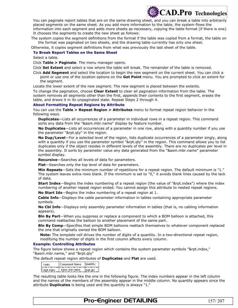
Pro-Engineer DETAILING 157/ 207
You can paginate report tables that are on the same drawing sheet, and you can break a table into arbitrarily placed segments on the same sheet. As you add more information to the table, the system flows the information into each segment and adds more sheets as necessary, copying the table format (if there is one). It chooses the segments to create the new sheet as follows:
The system copies the segment definitions from the format if the table was copied from a format, the table on the format was paginated on two sheets, and the drawing table currently has only one sheet.
Otherwise, it copies segment definitions from what was previously the last sheet of the table. To Break Report Tables on the Same Sheet Select a table. Click Table > Paginate. The menu manager opens. Click Set Extent and select a row where the table will break. The remainder of the table is removed. Click Add Segment and select the location to begin the new segment on the current sheet. You can click a
point or use one of the location options on the Get Point menu. You are prompted to click an extent for the segment.
Locate the lower extent of the new segment. The new segment is placed between the extents. To change the pagination, choose Clear Extent to clear all pagination information from the table. The system removes all segments other than the first, appends their contents to the first segment, erases the table, and draws it in its unpaginated state. Repeat Steps 2 through 4. About Formatting Repeat Regions by Attribute You can use the Table > Repeat Region > Attributes menu to format repeat region behavior in the following ways.
Duplicates—Lists all occurrences of a parameter in individual rows in a repeat region. This command sorts any data from the "&asm.mbr.name" display by feature number. No Duplicates—Lists all occurrences of a parameter in one row, along with a quantity number if you use the parameter "&rpt.qty" in the region. No Dup/Level—For a selected level of the region, lists duplicate occurrences of a parameter singly, along with a quantity if you use the parameter symbol "&rpt.qty" in the region. This command allows you to list duplicates only if the object resides in different levels of the assembly. There are no duplicates per level in the assembly. It sorts by parameter value any data generated from the "&asm.mbr.name" parameter symbol display. Recursive—Searches all levels of data for parameters. Flat—Searches only the top level of data for parameters. Min Repeats—Sets the minimum number of repetitions for a repeat region. The default minimum is "1." The system leaves extra rows blank. If the minimum is set to "0," it avoids blank lines caused by the lack of data. Start Index—Begins the index numbering of a repeat region (the value of "&rpt.index") where the index numbering of another repeat region ended. You cannot assign this attribute to nested repeat regions. No Start Idx—Begins the index numbering of a repeat region at 1. Cable Info—Displays the cable parameter information in tables containing appropriate parameter symbols. No Cbl Info—Displays only assembly parameter information in tables (that is, no cabling information appears). Bln By Part—When you suppress or replace a component to which a BOM balloon is attached, this command reattaches the balloon to another placement of the same part. Bln By Comp—Specifies that simple BOM balloons reattach themselves to whatever component replaced the one that originally owned the BOM balloon. Note: The template cell drives the number of digits of a quantity. In a two-directional repeat region, modifying the number of digits in the first column affects every column.
Example: Controlling Attributes The figure below shows a repeat region which contains the system parameter symbols "&rpt.index," "&asm.mbr.name," and "&rpt.qty" The default repeat region attributes of Duplicates and Flat are used.
The resulting table looks like the one in the following figure. The index numbers appear in the left column and the names of the members of the assembly appear in the middle column. No quantity appears since the attribute Duplicates is being used and the quantity is always "1."
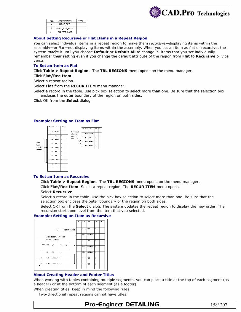
Pro-Engineer DETAILING 158/ 207
About Setting Recursive or Flat Items in a Repeat Region You can select individual items in a repeat region to make them recursive—displaying items within the assembly—or flat—not displaying items within the assembly. When you set an item as flat or recursive, the system marks it until you choose Default or Default All to change it. Items that you set individually remember their setting even if you change the default attribute of the region from Flat to Recursive or vice versa. To Set an Item as Flat Click Table > Repeat Region. The TBL REGIONS menu opens on the menu manager. Click Flat/Rec Item. Select a repeat region. Select Flat from the RECUR ITEM menu manager. Select a record in the table. Use pick box selection to select more than one. Be sure that the selection box
encloses the outer boundary of the region on both sides. Click OK from the Select dialog. Example: Setting an Item as Flat
To Set an Item as Recursive
Click Table > Repeat Region. The TBL REGIONS menu opens on the menu manager. Click Flat/Rec Item. Select a repeat region. The RECUR ITEM menu opens. Select Recursive. Select a record in the table. Use the pick box selection to select more than one. Be sure that the selection box encloses the outer boundary of the region on both sides. Select OK from the Select dialog. The system updates the repeat region to display the new order. The recursion starts one level from the item that you selected.
Example: Setting an Item as Recursive
About Creating Header and Footer Titles When working with tables containing multiple segments, you can place a title at the top of each segment (as a header) or at the bottom of each segment (as a footer). When creating titles, keep in mind the following rules:
Two-directional repeat regions cannot have titles.
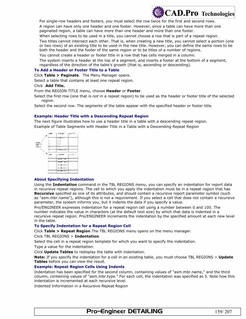
Pro-Engineer DETAILING 159/ 207
For single-row headers and footers, you must select the row twice for the first and second rows. A region can have only one header and one footer. However, since a table can have more than one paginated region, a table can have more than one header and more than one footer. When selecting rows to be used in a title, you cannot choose a row that is part of a repeat region. Two titles cannot intersect each other. That is, when creating a new title, you cannot select a portion (one or two rows) of an existing title to be used in the new title. However, you can define the same rows to be both the header and the footer of the same region or to be titles of a number of regions. You cannot create a header or footer title in a row that has cells merged in a column. The system inserts a header at the top of a segment, and inserts a footer at the bottom of a segment, regardless of the direction of the table’s growth (that is, ascending or descending).
To Add a Header or Footer Title to a Table Click Table > Paginate. The Menu Manager opens. Select a table that contains at least one repeat region. Click Add Title. From the REGION TITLE menu, choose Header or Footer. Select the first row (one that is not in a repeat region) to be used as the header or footer title of the selected
region. Select the second row. The segments of the table appear with the specified header or footer title. Example: Header Title with a Descending Repeat Region The next figure illustrates how to use a header title in a table with a descending repeat region. Example of Table Segments with Header Title in a Table with a Descending Repeat Region
About Specifying Indentation Using the Indentation command in the TBL REGIONS menu, you can specify an indentation for report data in recursive repeat regions. The cell to which you apply the indentation must be in a repeat region that has Recursive specified as one of its attributes, and should contain a recursive report parameter symbol (such as "asm.mbr.name"), although this is not a requirement. If you select a cell that does not contain a recursive parameter, the system informs you, but it indents the data if you specify a value. Pro/ENGINEER expresses indentation for a repeat region cell using a number between 0 and 100. The number indicates the value in characters (at the default text size) by which that data is indented in a recursive repeat region. Pro/ENGINEER increments the indentation by the specified amount at each new level in the table. To Specify Indentation for a Repeat Region Cell Click Table > Repeat Region The TBL REGIONS menu opens on the menu manager. Click TBL REGIONS > Indentation. Select the cell in a repeat region template for which you want to specify the indentation. Type a value for the indentation. Click Update Tables to redisplay the table with indentation. Note: If you specify the indentation for a cell in an existing table, you must choose TBL REGIONS > Update Tables before you can view the result. Example: Repeat Region Cells Using Indents Indentation has been specified for the second column, containing values of "asm.mbr.name," and the third column, containing values of "asm.mbr.type." For each cell, the indentation was specified as 5. Note how this indentation is incremented at each recursive level. Indented Information in a Recursive Repeat Region
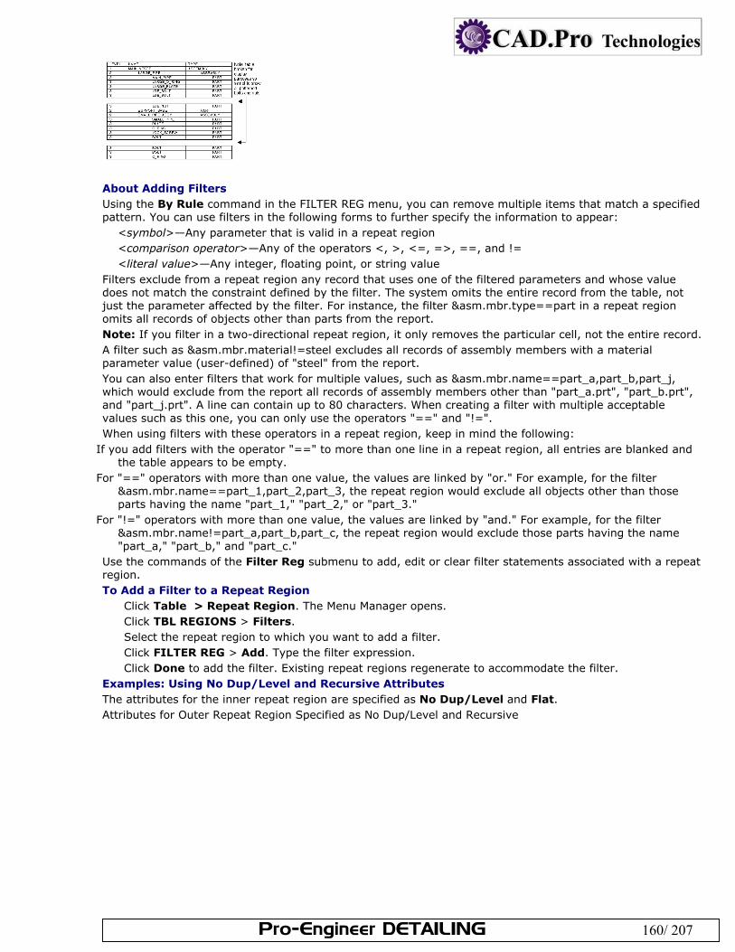
Pro-Engineer DETAILING 160/ 207
About Adding Filters Using the By Rule command in the FILTER REG menu, you can remove multiple items that match a specified pattern. You can use filters in the following forms to further specify the information to appear:
<symbol>—Any parameter that is valid in a repeat region <comparison operator>—Any of the operators <, >, <=, =>, ==, and != <literal value>—Any integer, floating point, or string value
Filters exclude from a repeat region any record that uses one of the filtered parameters and whose value does not match the constraint defined by the filter. The system omits the entire record from the table, not just the parameter affected by the filter. For instance, the filter &asm.mbr.type==part in a repeat region omits all records of objects other than parts from the report. Note: If you filter in a two-directional repeat region, it only removes the particular cell, not the entire record. A filter such as &asm.mbr.material!=steel excludes all records of assembly members with a material parameter value (user-defined) of "steel" from the report. You can also enter filters that work for multiple values, such as &asm.mbr.name==part_a,part_b,part_j, which would exclude from the report all records of assembly members other than "part_a.prt", "part_b.prt", and "part_j.prt". A line can contain up to 80 characters. When creating a filter with multiple acceptable values such as this one, you can only use the operators "==" and "!=". When using filters with these operators in a repeat region, keep in mind the following:
If you add filters with the operator "==" to more than one line in a repeat region, all entries are blanked and the table appears to be empty.
For "==" operators with more than one value, the values are linked by "or." For example, for the filter &asm.mbr.name==part_1,part_2,part_3, the repeat region would exclude all objects other than those parts having the name "part_1," "part_2," or "part_3."
For "!=" operators with more than one value, the values are linked by "and." For example, for the filter &asm.mbr.name!=part_a,part_b,part_c, the repeat region would exclude those parts having the name "part_a," "part_b," and "part_c."
Use the commands of the Filter Reg submenu to add, edit or clear filter statements associated with a repeat region. To Add a Filter to a Repeat Region
Click Table > Repeat Region. The Menu Manager opens. Click TBL REGIONS > Filters. Select the repeat region to which you want to add a filter. Click FILTER REG > Add. Type the filter expression. Click Done to add the filter. Existing repeat regions regenerate to accommodate the filter.
Examples: Using No Dup/Level and Recursive Attributes The attributes for the inner repeat region are specified as No Dup/Level and Flat. Attributes for Outer Repeat Region Specified as No Dup/Level and Recursive
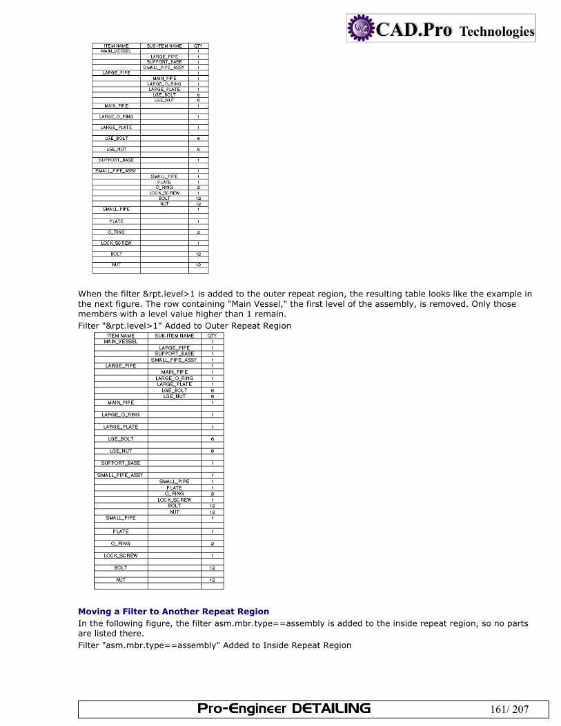
Pro-Engineer DETAILING 161/ 207
When the filter &rpt.level>1 is added to the outer repeat region, the resulting table looks like the example in the next figure. The row containing "Main Vessel," the first level of the assembly, is removed. Only those members with a level value higher than 1 remain. Filter "&rpt.level>1" Added to Outer Repeat Region
Moving a Filter to Another Repeat Region In the following figure, the filter asm.mbr.type==assembly is added to the inside repeat region, so no parts are listed there. Filter "asm.mbr.type==assembly" Added to Inside Repeat Region
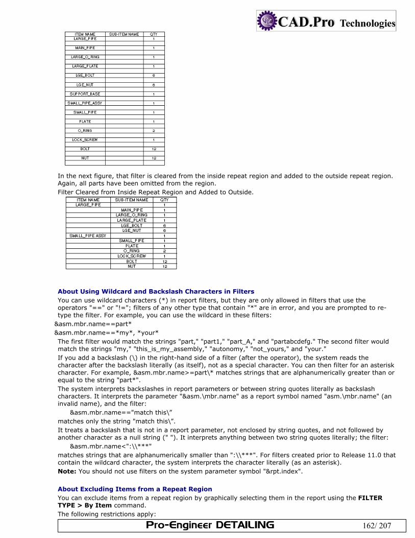
Pro-Engineer DETAILING 162/ 207
In the next figure, that filter is cleared from the inside repeat region and added to the outside repeat region. Again, all parts have been omitted from the region. Filter Cleared from Inside Repeat Region and Added to Outside.
About Using Wildcard and Backslash Characters in Filters You can use wildcard characters (*) in report filters, but they are only allowed in filters that use the operators "==" or "!="; filters of any other type that contain "*" are in error, and you are prompted to re-type the filter. For example, you can use the wildcard in these filters:
&asm.mbr.name==part* &asm.mbr.name==*my*, *your* The first filter would match the strings "part," "part1," "part_A," and "partabcdefg." The second filter would match the strings "my," "this_is_my_assembly," "autonomy," "not_yours," and "your." If you add a backslash (\) in the right-hand side of a filter (after the operator), the system reads the character after the backslash literally (as itself), not as a special character. You can then filter for an asterisk character. For example, &asm.mbr.name>=part\* matches strings that are alphanumerically greater than or equal to the string "part*". The system interprets backslashes in report parameters or between string quotes literally as backslash characters. It interprets the parameter "&asm.\mbr.name" as a report symbol named "asm.\mbr.name" (an invalid name), and the filter:
&asm.mbr.name=="match this\” matches only the string "match this\”. It treats a backslash that is not in a report parameter, not enclosed by string quotes, and not followed by another character as a null string (" "). It interprets anything between two string quotes literally; the filter:
&asm.mbr.name<":\\***" matches strings that are alphanumerically smaller than ":\\***". For filters created prior to Release 11.0 that contain the wildcard character, the system interprets the character literally (as an asterisk). Note: You should not use filters on the system parameter symbol "&rpt.index".
About Excluding Items from a Repeat Region You can exclude items from a repeat region by graphically selecting them in the report using the FILTER TYPE > By Item command. The following restrictions apply:
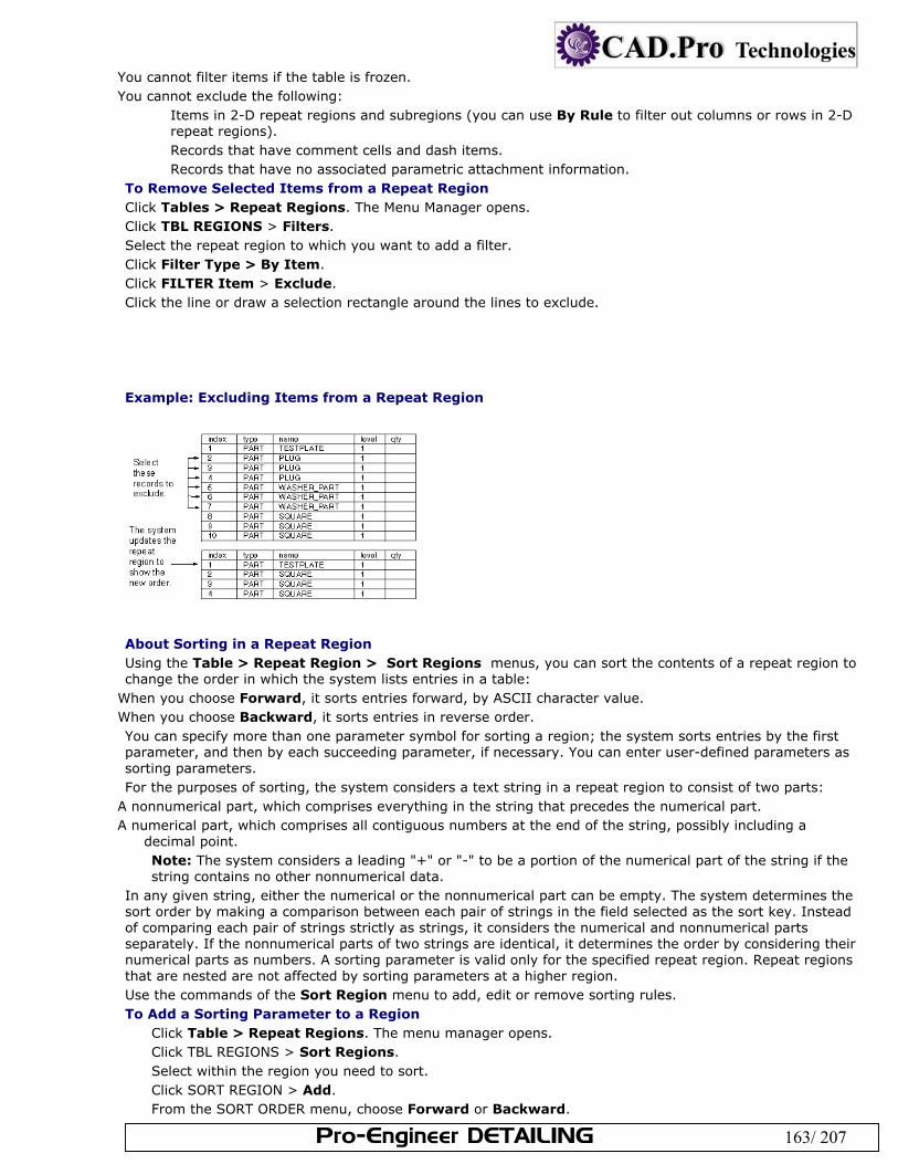
Pro-Engineer DETAILING 163/ 207
You cannot filter items if the table is frozen. You cannot exclude the following:
Items in 2-D repeat regions and subregions (you can use By Rule to filter out columns or rows in 2-D repeat regions). Records that have comment cells and dash items. Records that have no associated parametric attachment information.
To Remove Selected Items from a Repeat Region Click Tables > Repeat Regions. The Menu Manager opens. Click TBL REGIONS > Filters. Select the repeat region to which you want to add a filter. Click Filter Type > By Item. Click FILTER Item > Exclude. Click the line or draw a selection rectangle around the lines to exclude. Example: Excluding Items from a Repeat Region
About Sorting in a Repeat Region Using the Table > Repeat Region > Sort Regions menus, you can sort the contents of a repeat region to change the order in which the system lists entries in a table:
When you choose Forward, it sorts entries forward, by ASCII character value. When you choose Backward, it sorts entries in reverse order. You can specify more than one parameter symbol for sorting a region; the system sorts entries by the first parameter, and then by each succeeding parameter, if necessary. You can enter user-defined parameters as sorting parameters. For the purposes of sorting, the system considers a text string in a repeat region to consist of two parts:
A nonnumerical part, which comprises everything in the string that precedes the numerical part. A numerical part, which comprises all contiguous numbers at the end of the string, possibly including a
decimal point. Note: The system considers a leading "+" or "-" to be a portion of the numerical part of the string if the string contains no other nonnumerical data.
In any given string, either the numerical or the nonnumerical part can be empty. The system determines the sort order by making a comparison between each pair of strings in the field selected as the sort key. Instead of comparing each pair of strings strictly as strings, it considers the numerical and nonnumerical parts separately. If the nonnumerical parts of two strings are identical, it determines the order by considering their numerical parts as numbers. A sorting parameter is valid only for the specified repeat region. Repeat regions that are nested are not affected by sorting parameters at a higher region. Use the commands of the Sort Region menu to add, edit or remove sorting rules. To Add a Sorting Parameter to a Region
Click Table > Repeat Regions. The menu manager opens. Click TBL REGIONS > Sort Regions. Select within the region you need to sort. Click SORT REGION > Add. From the SORT ORDER menu, choose Forward or Backward.
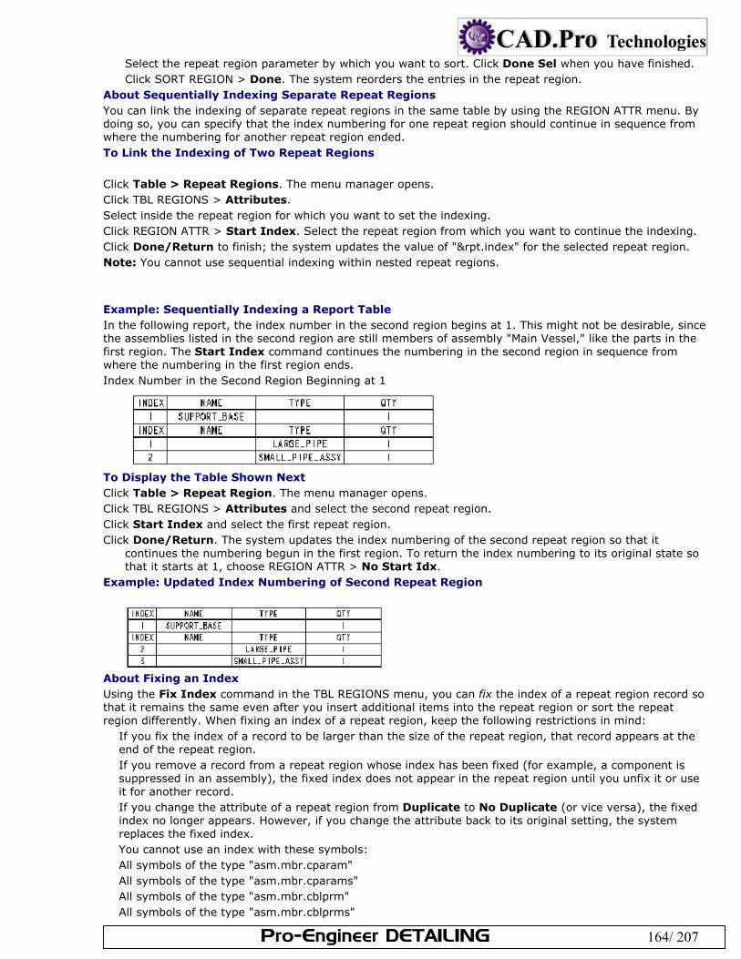
Pro-Engineer DETAILING 164/ 207
Select the repeat region parameter by which you want to sort. Click Done Sel when you have finished. Click SORT REGION > Done. The system reorders the entries in the repeat region.
About Sequentially Indexing Separate Repeat Regions You can link the indexing of separate repeat regions in the same table by using the REGION ATTR menu. By doing so, you can specify that the index numbering for one repeat region should continue in sequence from where the numbering for another repeat region ended. To Link the Indexing of Two Repeat Regions Click Table > Repeat Regions. The menu manager opens. Click TBL REGIONS > Attributes. Select inside the repeat region for which you want to set the indexing. Click REGION ATTR > Start Index. Select the repeat region from which you want to continue the indexing. Click Done/Return to finish; the system updates the value of "&rpt.index" for the selected repeat region. Note: You cannot use sequential indexing within nested repeat regions. Example: Sequentially Indexing a Report Table In the following report, the index number in the second region begins at 1. This might not be desirable, since the assemblies listed in the second region are still members of assembly "Main Vessel," like the parts in the first region. The Start Index command continues the numbering in the second region in sequence from where the numbering in the first region ends. Index Number in the Second Region Beginning at 1
To Display the Table Shown Next Click Table > Repeat Region. The menu manager opens. Click TBL REGIONS > Attributes and select the second repeat region. Click Start Index and select the first repeat region. Click Done/Return. The system updates the index numbering of the second repeat region so that it
continues the numbering begun in the first region. To return the index numbering to its original state so that it starts at 1, choose REGION ATTR > No Start Idx.
Example: Updated Index Numbering of Second Repeat Region
About Fixing an Index Using the Fix Index command in the TBL REGIONS menu, you can fix the index of a repeat region record so that it remains the same even after you insert additional items into the repeat region or sort the repeat region differently. When fixing an index of a repeat region, keep the following restrictions in mind:
If you fix the index of a record to be larger than the size of the repeat region, that record appears at the end of the repeat region. If you remove a record from a repeat region whose index has been fixed (for example, a component is suppressed in an assembly), the fixed index does not appear in the repeat region until you unfix it or use it for another record. If you change the attribute of a repeat region from Duplicate to No Duplicate (or vice versa), the fixed index no longer appears. However, if you change the attribute back to its original setting, the system replaces the fixed index. You cannot use an index with these symbols: All symbols of the type "asm.mbr.cparam" All symbols of the type "asm.mbr.cparams" All symbols of the type "asm.mbr.cblprm" All symbols of the type "asm.mbr.cblprms"
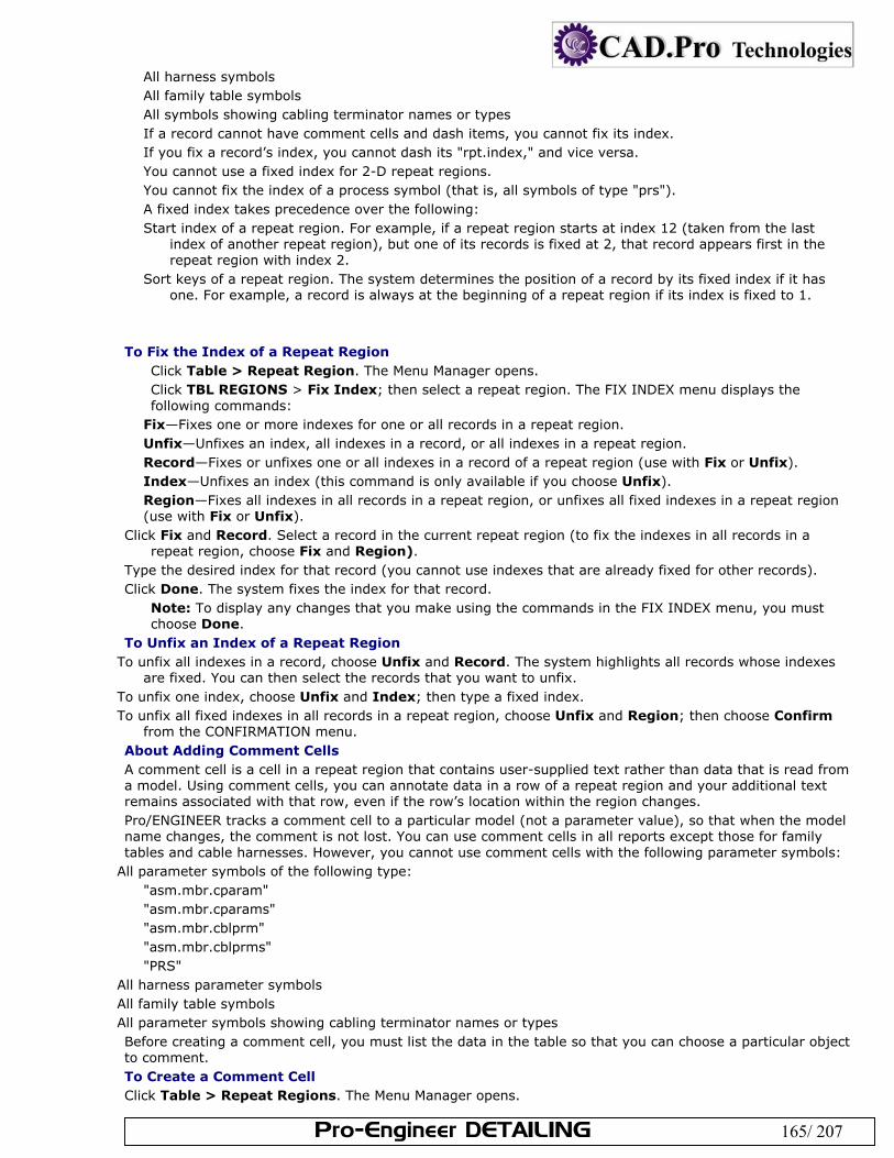
Pro-Engineer DETAILING 165/ 207
All harness symbols All family table symbols All symbols showing cabling terminator names or types If a record cannot have comment cells and dash items, you cannot fix its index. If you fix a record’s index, you cannot dash its "rpt.index," and vice versa. You cannot use a fixed index for 2-D repeat regions. You cannot fix the index of a process symbol (that is, all symbols of type "prs"). A fixed index takes precedence over the following: Start index of a repeat region. For example, if a repeat region starts at index 12 (taken from the last
index of another repeat region), but one of its records is fixed at 2, that record appears first in the repeat region with index 2.
Sort keys of a repeat region. The system determines the position of a record by its fixed index if it has one. For example, a record is always at the beginning of a repeat region if its index is fixed to 1.
To Fix the Index of a Repeat Region
Click Table > Repeat Region. The Menu Manager opens. Click TBL REGIONS > Fix Index; then select a repeat region. The FIX INDEX menu displays the following commands:
Fix—Fixes one or more indexes for one or all records in a repeat region. Unfix—Unfixes an index, all indexes in a record, or all indexes in a repeat region. Record—Fixes or unfixes one or all indexes in a record of a repeat region (use with Fix or Unfix). Index—Unfixes an index (this command is only available if you choose Unfix). Region—Fixes all indexes in all records in a repeat region, or unfixes all fixed indexes in a repeat region (use with Fix or Unfix).
Click Fix and Record. Select a record in the current repeat region (to fix the indexes in all records in a repeat region, choose Fix and Region).
Type the desired index for that record (you cannot use indexes that are already fixed for other records). Click Done. The system fixes the index for that record.
Note: To display any changes that you make using the commands in the FIX INDEX menu, you must choose Done.
To Unfix an Index of a Repeat Region To unfix all indexes in a record, choose Unfix and Record. The system highlights all records whose indexes
are fixed. You can then select the records that you want to unfix. To unfix one index, choose Unfix and Index; then type a fixed index. To unfix all fixed indexes in all records in a repeat region, choose Unfix and Region; then choose Confirm
from the CONFIRMATION menu. About Adding Comment Cells A comment cell is a cell in a repeat region that contains user-supplied text rather than data that is read from a model. Using comment cells, you can annotate data in a row of a repeat region and your additional text remains associated with that row, even if the row’s location within the region changes. Pro/ENGINEER tracks a comment cell to a particular model (not a parameter value), so that when the model name changes, the comment is not lost. You can use comment cells in all reports except those for family tables and cable harnesses. However, you cannot use comment cells with the following parameter symbols:
All parameter symbols of the following type: "asm.mbr.cparam" "asm.mbr.cparams" "asm.mbr.cblprm" "asm.mbr.cblprms" "PRS"
All harness parameter symbols All family table symbols All parameter symbols showing cabling terminator names or types Before creating a comment cell, you must list the data in the table so that you can choose a particular object to comment. To Create a Comment Cell Click Table > Repeat Regions. The Menu Manager opens.
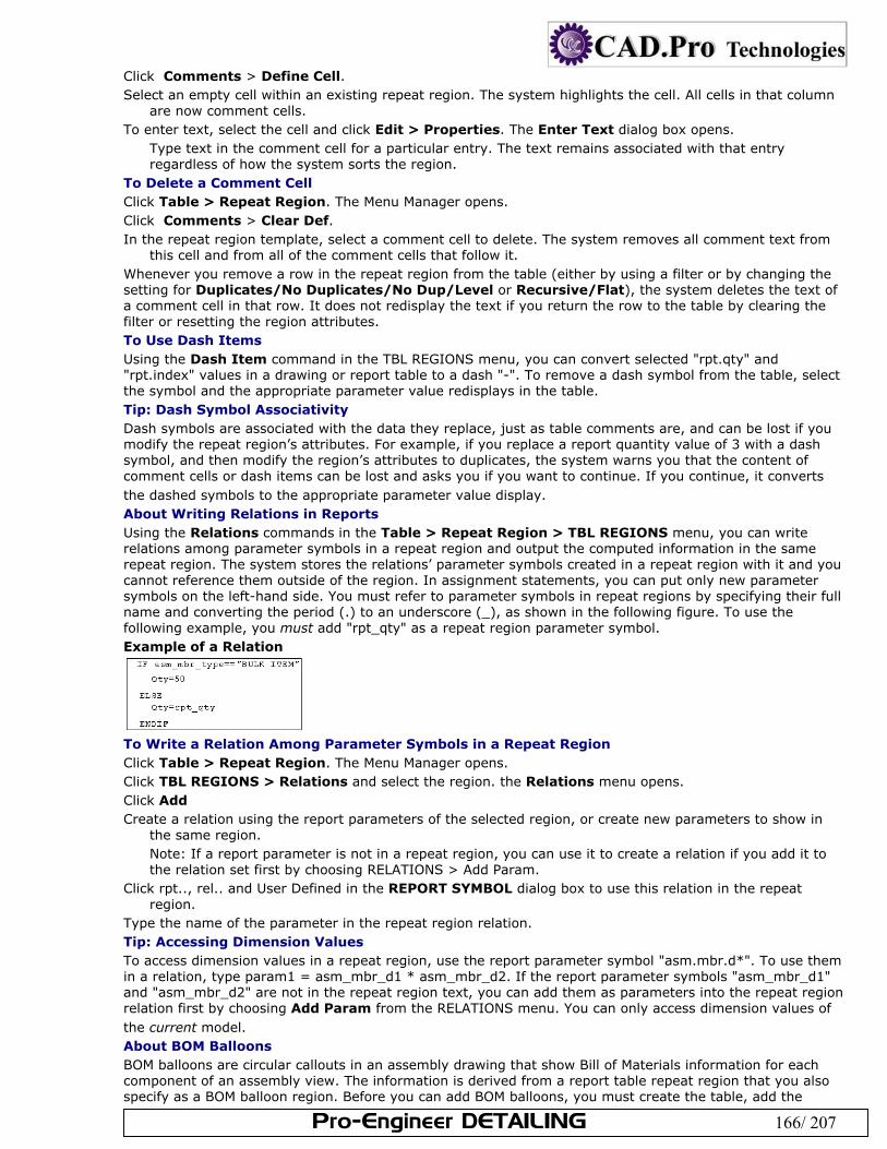
Pro-Engineer DETAILING 166/ 207
Click Comments > Define Cell. Select an empty cell within an existing repeat region. The system highlights the cell. All cells in that column
are now comment cells. To enter text, select the cell and click Edit > Properties. The Enter Text dialog box opens.
Type text in the comment cell for a particular entry. The text remains associated with that entry regardless of how the system sorts the region.
To Delete a Comment Cell Click Table > Repeat Region. The Menu Manager opens. Click Comments > Clear Def. In the repeat region template, select a comment cell to delete. The system removes all comment text from
this cell and from all of the comment cells that follow it. Whenever you remove a row in the repeat region from the table (either by using a filter or by changing the setting for Duplicates/No Duplicates/No Dup/Level or Recursive/Flat), the system deletes the text of a comment cell in that row. It does not redisplay the text if you return the row to the table by clearing the filter or resetting the region attributes. To Use Dash Items Using the Dash Item command in the TBL REGIONS menu, you can convert selected "rpt.qty" and "rpt.index" values in a drawing or report table to a dash "-". To remove a dash symbol from the table, select the symbol and the appropriate parameter value redisplays in the table. Tip: Dash Symbol Associativity Dash symbols are associated with the data they replace, just as table comments are, and can be lost if you modify the repeat region’s attributes. For example, if you replace a report quantity value of 3 with a dash symbol, and then modify the region’s attributes to duplicates, the system warns you that the content of comment cells or dash items can be lost and asks you if you want to continue. If you continue, it converts the dashed symbols to the appropriate parameter value display. About Writing Relations in Reports Using the Relations commands in the Table > Repeat Region > TBL REGIONS menu, you can write relations among parameter symbols in a repeat region and output the computed information in the same repeat region. The system stores the relations’ parameter symbols created in a repeat region with it and you cannot reference them outside of the region. In assignment statements, you can put only new parameter symbols on the left-hand side. You must refer to parameter symbols in repeat regions by specifying their full name and converting the period (.) to an underscore (_), as shown in the following figure. To use the following example, you must add "rpt_qty" as a repeat region parameter symbol. Example of a Relation
To Write a Relation Among Parameter Symbols in a Repeat Region Click Table > Repeat Region. The Menu Manager opens. Click TBL REGIONS > Relations and select the region. the Relations menu opens. Click Add Create a relation using the report parameters of the selected region, or create new parameters to show in
the same region. Note: If a report parameter is not in a repeat region, you can use it to create a relation if you add it to the relation set first by choosing RELATIONS > Add Param.
Click rpt.., rel.. and User Defined in the REPORT SYMBOL dialog box to use this relation in the repeat region.
Type the name of the parameter in the repeat region relation. Tip: Accessing Dimension Values To access dimension values in a repeat region, use the report parameter symbol "asm.mbr.d*". To use them in a relation, type param1 = asm_mbr_d1 * asm_mbr_d2. If the report parameter symbols "asm_mbr_d1" and "asm_mbr_d2" are not in the repeat region text, you can add them as parameters into the repeat region relation first by choosing Add Param from the RELATIONS menu. You can only access dimension values of the current model. About BOM Balloons BOM balloons are circular callouts in an assembly drawing that show Bill of Materials information for each component of an assembly view. The information is derived from a report table repeat region that you also specify as a BOM balloon region. Before you can add BOM balloons, you must create the table, add the
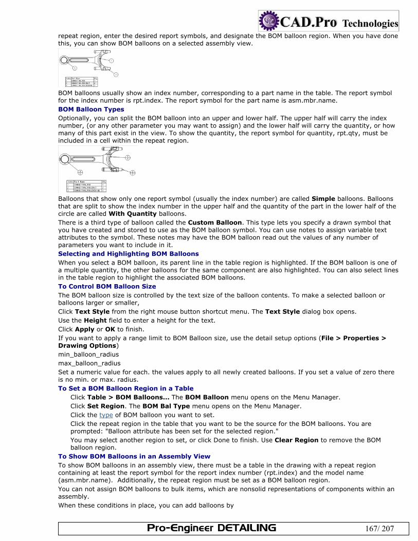
Pro-Engineer DETAILING 167/ 207
repeat region, enter the desired report symbols, and designate the BOM balloon region. When you have done this, you can show BOM balloons on a selected assembly view.
BOM balloons usually show an index number, corresponding to a part name in the table. The report symbol for the index number is rpt.index. The report symbol for the part name is asm.mbr.name. BOM Balloon Types Optionally, you can split the BOM balloon into an upper and lower half. The upper half will carry the index number, (or any other parameter you may want to assign) and the lower half will carry the quantity, or how many of this part exist in the view. To show the quantity, the report symbol for quantity, rpt.qty, must be included in a cell within the repeat region.
Balloons that show only one report symbol (usually the index number) are called Simple balloons. Balloons that are split to show the index number in the upper half and the quantity of the part in the lower half of the circle are called With Quantity balloons. There is a third type of balloon called the Custom Balloon. This type lets you specify a drawn symbol that you have created and stored to use as the BOM balloon symbol. You can use notes to assign variable text attributes to the symbol. These notes may have the BOM balloon read out the values of any number of parameters you want to include in it. Selecting and Highlighting BOM Balloons When you select a BOM balloon, its parent line in the table region is highlighted. If the BOM balloon is one of a multiple quantity, the other balloons for the same component are also highlighted. You can also select lines in the table region to highlight the associated BOM balloons. To Control BOM Balloon Size The BOM balloon size is controlled by the text size of the balloon contents. To make a selected balloon or balloons larger or smaller, Click Text Style from the right mouse button shortcut menu. The Text Style dialog box opens. Use the Height field to enter a height for the text. Click Apply or OK to finish. If you want to apply a range limit to BOM Balloon size, use the detail setup options (File > Properties > Drawing Options) min_balloon_radius max_balloon_radius Set a numeric value for each. the values apply to all newly created balloons. If you set a value of zero there is no min. or max. radius. To Set a BOM Balloon Region in a Table
Click Table > BOM Balloons... The BOM Balloon menu opens on the Menu Manager. Click Set Region. The BOM Bal Type menu opens on the Menu Manager. Click the type of BOM balloon you want to set. Click the repeat region in the table that you want to be the source for the BOM balloons. You are prompted: "Balloon attribute has been set for the selected region." You may select another region to set, or click Done to finish. Use Clear Region to remove the BOM balloon region.
To Show BOM Balloons in an Assembly View To show BOM balloons in an assembly view, there must be a table in the drawing with a repeat region containing at least the report symbol for the report index number (rpt.index) and the model name (asm.mbr.name). Additionally, the repeat region must be set as a BOM balloon region. You can not assign BOM balloons to bulk items, which are nonsolid representations of components within an assembly. When these conditions in place, you can add balloons by
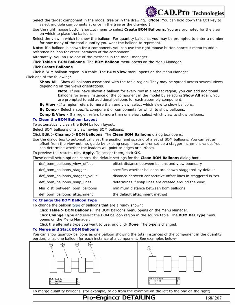
Pro-Engineer DETAILING 168/ 207
Select the target component in the model tree or in the drawing, (Note: You can hold down the Ctrl key to select multiple components at once in the tree or the drawing.)
Use the right mouse button shortcut menu to select Create BOM Balloons. You are prompted for the view on which to place the balloons.
Select the view in which to show the balloon. For quantity balloons, you may be prompted to enter a number for how many of the total quantity you want the balloon to represent.
Note: If a balloon is shown for a component, you can use the right mouse button shortcut menu to add a reference balloon for other instances of the component. Alternately, you an use one of the methods in the menu manager- Click Table > BOM Balloons. The BOM Balloon menu opens on the Menu Manager. Click Create Balloons. Click a BOM balloon region in a table. The BOM View menu opens on the Menu Manager.
Click one of the following: Show All - Show all balloons associated with the table region. They may be spread across several views depending on the views orientations.
Note: If you have shown a balloon for every row in a repeat region, you can add additional balloons for every instance of the component in the model by selecting Show All again. You are prompted to add additional balloons for each assembly component.
By View - If a region refers to more than one view, select which view to show balloons. By Comp - Select a specific component or components for which to show balloons. Comp & View - If a region refers to more than one view, select which view to show balloons.
To Clean the BOM Balloon Layout To automatically clean the BOM balloon layout: Select BOM balloons or a view having BOM balloons. Click Edit > Cleanup > BOM balloons. The Clean BOM Balloons dialog box opens. Use the dialog box to automatically set the position and spacing of a set of BOM balloons. You can set an
offset from the view outline, guide by existing snap lines, and-or set up a stagger increment value. You can determine whether the leaders will point to edges or surfaces.
To preview the results, click Apply. To accept them, click OK. These detail setup options control the default settings for the Clean BOM Balloons dialog box:
def_bom_balloons_view_offset offset distance between ballons and view boundary
def_bom_balloons_stagger specifies whether balloons are shown staggered by default
def_bom_balloons_stagger_value distance between consecutive offset lines in staggered is Yes
def_bom_balloons_snap_lines determines if snap lines are created around the view
Min_dist_between_bom_balloons minimum distance between bom balloons
def_bom_balloons_attachment the default attachment method
To Change the BOM Balloon Type To change the balloon type of balloons that are already shown:
Click Table > BOM Balloons. The BOM Balloons menu opens on the Menu Manager. Click Change Type and select the BOM balloon region in the source table. The BOM Bal Type menu opens on the Menu Manager. Click the alternate type you want to use, and click Done. The type is changed.
To Merge and Stack BOM Balloons You can show quantity balloons as one balloon showing the total instances of the component in the quantity portion, or as one balloon for each instance of a component. See examples below-
To merge quantity balloons, (for example, to go from the example on the left to the one on the right)
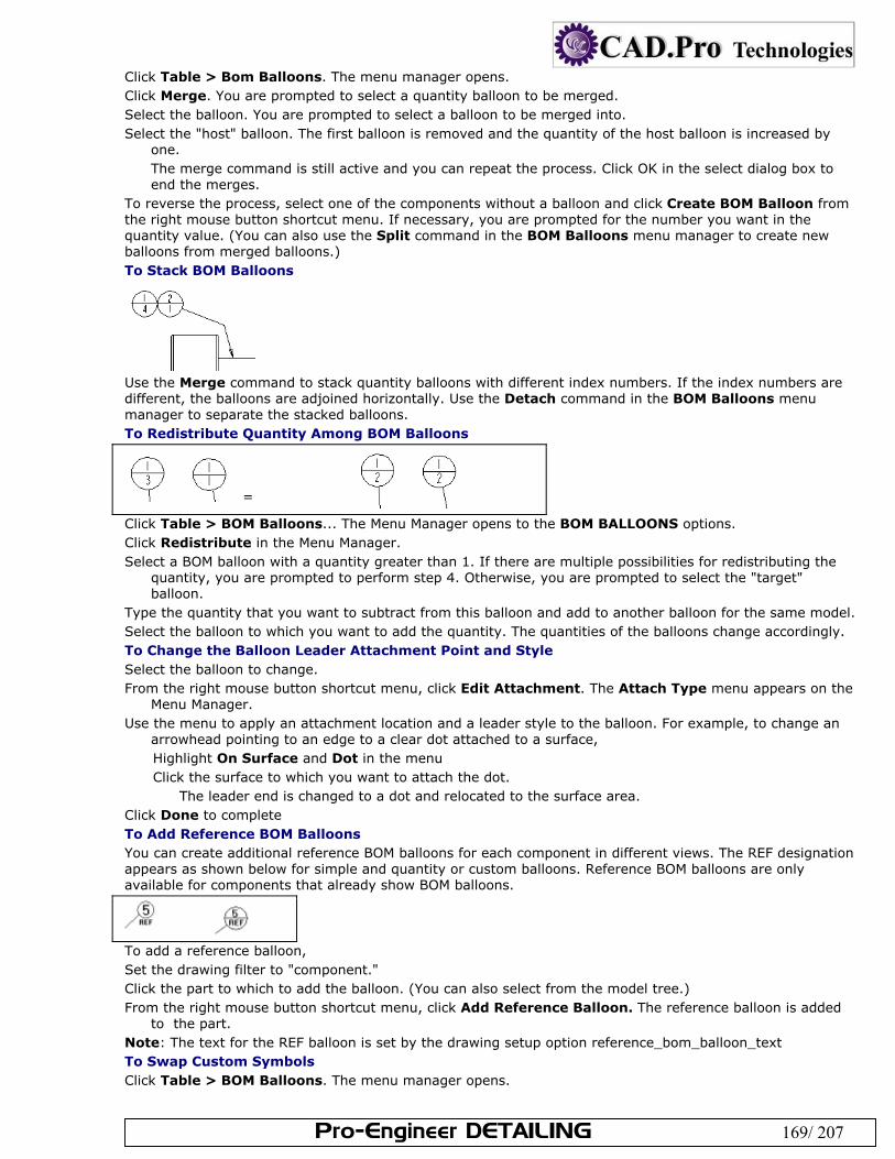
Pro-Engineer DETAILING 169/ 207
Click Table > Bom Balloons. The menu manager opens. Click Merge. You are prompted to select a quantity balloon to be merged. Select the balloon. You are prompted to select a balloon to be merged into. Select the "host" balloon. The first balloon is removed and the quantity of the host balloon is increased by
one. The merge command is still active and you can repeat the process. Click OK in the select dialog box to end the merges.
To reverse the process, select one of the components without a balloon and click Create BOM Balloon from the right mouse button shortcut menu. If necessary, you are prompted for the number you want in the quantity value. (You can also use the Split command in the BOM Balloons menu manager to create new balloons from merged balloons.) To Stack BOM Balloons
Use the Merge command to stack quantity balloons with different index numbers. If the index numbers are different, the balloons are adjoined horizontally. Use the Detach command in the BOM Balloons menu manager to separate the stacked balloons. To Redistribute Quantity Among BOM Balloons
= Click Table > BOM Balloons... The Menu Manager opens to the BOM BALLOONS options. Click Redistribute in the Menu Manager. Select a BOM balloon with a quantity greater than 1. If there are multiple possibilities for redistributing the
quantity, you are prompted to perform step 4. Otherwise, you are prompted to select the "target" balloon.
Type the quantity that you want to subtract from this balloon and add to another balloon for the same model. Select the balloon to which you want to add the quantity. The quantities of the balloons change accordingly. To Change the Balloon Leader Attachment Point and Style Select the balloon to change. From the right mouse button shortcut menu, click Edit Attachment. The Attach Type menu appears on the
Menu Manager. Use the menu to apply an attachment location and a leader style to the balloon. For example, to change an
arrowhead pointing to an edge to a clear dot attached to a surface, Highlight On Surface and Dot in the menu Click the surface to which you want to attach the dot.
The leader end is changed to a dot and relocated to the surface area. Click Done to complete To Add Reference BOM Balloons You can create additional reference BOM balloons for each component in different views. The REF designation appears as shown below for simple and quantity or custom balloons. Reference BOM balloons are only available for components that already show BOM balloons.
To add a reference balloon, Set the drawing filter to "component." Click the part to which to add the balloon. (You can also select from the model tree.) From the right mouse button shortcut menu, click Add Reference Balloon. The reference balloon is added
to the part. Note: The text for the REF balloon is set by the drawing setup option reference_bom_balloon_text To Swap Custom Symbols Click Table > BOM Balloons. The menu manager opens.
Pro-Engineer DETAILING 170/ 207
Click BOM BALLOONS > Alt Symbol. (If multiple regions are present, you are prompted to select a balloon region.)
Select quantity or custom balloons of the selected repeat region, then click OK. From the GET SYMBOL menu, select a user-defined symbol. Any selected balloons change to match the
selected symbol, and the system redisplays the new balloons using the selected symbol for any selected components.
For regions that use a user-defined symbol to display balloons, choose GET SYMBOL > Reg Default. The selected balloons revert to the default symbol of the region, and the system shows new balloons for the selected components using that symbol. Note: You cannot change individual simple-customized balloons to quantity-customized balloons, and vice versa. All balloons for any given region must be either quantity or simple balloons.
Creating Customized BOM Balloons Using the Custom command in the BOM BAL TYPE menu, you can create customized balloons with user-defined symbol instances. When you use a customized symbol to show balloons, the system substitutes variable text with corresponding report parameters. If the default value of the variable text matches a report symbol specification, it displays the value of that report symbol in the symbol. For example, if the variable text default value is asm.mbr.name, the system displays the member name in the balloon. It updates (in the symbol instance) only the report parameters that it displays in the balloon region; other variable texts simply display their default values. In addition to report parameters displayed in the table, the system uses two special keywords as default values for variable text: it replaces "qty" with the quantity, as in default quantity balloons, and it treats "index" as the index field in default balloons. By default, for variable text whose default value is "index," it fills them in with the value of "rpt.index." You can use the Set Param command in the BOM BALLOON menu to specify a different parameter for the index field. The system considers a customized balloon to be a quantity custom balloon if it contains variable text whose default value is "qty." Tip: Setting the Default Arrow Style for BOM Balloons To set the default arrow style for BOM balloons, use the drawing setup file options def_bom_balloons_edge_att_sym and def_bom_balloons_surf_att_sym The respective choices are listed in the options pull-down list in the File > Properties > Drawing Options dialog box. About Controlling Drawing Details with Layers You can organize and control your drawing detailing by assigning drawing items to layers. You can hide and show layers as necessary, which allows you control the display of multiple drawing items simultaneously. For example, you can assign notes to a specific layer and then hide them before plotting the drawing. Using layers, you can organize items and streamline selection because all the layer items are treated as a group. Layers can include other items in a Pro/ENGINEER database such as features, dimensions, notes, geometric tolerances, and other layers. You can place drawing items on layers in the following ways:
Manually—Place the items on a layer after they are added to the drawing. You can individually select the items to add or you can use region selection.
Default Layers—Define specific items to automatically place on a layer as they are created. Detail items, such as driven dimensions, draft entities, and snap lines can be added using this method. You can either specify detail items using the individual default layer settings or you can add all detail items to a default layer. The same default layers that exist in 3D mode, for example layers for curves, mechanical features, or rounds, exist in Detail mode.
Although drawing views do not have individual layers for each view, you can control the display status of drawing layers for individual views by overriding the model layer status. Controlling the layer display for individual views enables you to:
Include items from parts and assemblies directly in a drawing layer without including them on a layer in a model.
Control the display of drawing layers to include items from the model without marking the model as changed. Vary the display of a single model in different drawing views. Layers and their contents can be accessed from the Model Tree. To show the Layer Tree, click Show> Layer Tree on the Model Tree window. The display status (hidden, unhidden, or isolated) of a layer controls whether or not items in the layer are displayed. Note: When blanking or displaying layers containing datum curves, the hidden lines of three dimensional objects are recalculated to ensure the drawing is updated and accurate. Utilizing Default Layers in Drawings
Pro-Engineer DETAILING 171/ 207
You can automatically place specific drawing item types on a layer by defining a default layer. You define which item type to automatically place by setting the def_layer configuration option. As soon as the item is created or shown in the drawing it is simultaneously placed on the layer. For example, if you use the layer_dim_<layer name> configuration option, as soon as a dimension is created or shown it is placed on the designated layer. You can only add one drawing item type to each default layer. Managing Layers with the Same Name Items on layers with the same name are treated similarly. You can set the display of model layers to mirror the display of drawing layers with the same name. For example, if you blank the drawing layer datums, Pro/E also blanks all items on the datums layers for the model components. If the model is an assembly and you add a component with a layer of the same name, Pro/E automatically sets the display of any items on a model layer named datums to be the same as the drawing layer. To keep one component datums layer from being affected, put the desired layer directly on another drawing layer. To set the display of layers with the same name, do one of the following:
On the Model Tree, click Settings > Drawing Layer Status, and select the second check box (Change display of model layers with the same names in drawing only) in the Layer Status Control dialog box..
Set the draw_layer_overrides_model drawing setup file option to yes. If you set this option to no (the default value), Pro/E ignores nondrawing layers when you set the display status of layers in the drawing model with the same name.
With the exception of ruled layers, if you activate a layer that has the same name as another layer, each layer with that name is activated. For example, if the drawing and the drawing model have a layer named my_layer, activating one of these layers causes the other to be activated. Designated items supported in both modes (driven dimensions, surface finish symbols, and geometric tolerances) are placed on both layers, while unsupported items are only placed on the drawing layer. Invisible Drawing Model Items Items in the drawing model are visible by default unless one of these conditions is met:
The item is included directly on a drawing layer. The item is on a part or assembly layer with the same name as a drawing layer and the drawing setup file
option draw_layer_overrides_model is set to yes. The item is on a part or assembly layer that has been included in a drawing layer. For these three cases, the drawing layer status information determines whether to show the item. To Place Drawing Items on Layers Placing drawing items on layers enables you to control the display of multiple items simultaneously. Layers are a good way to organize items and can streamline selection since all the layer items are treated as a group. You can place drawing items on layers manually or automatically. To Manually Place Drawing Items on Layers On the Model Tree, click Show > Layer Tree. Any existing layers are listed. Define the layer to place the drawing items on:
To create a new layer, click Layer > New Layer. The Layer Properties dialog box opens. To place the items on an existing layer, right-click on the layer and click Layer Properties. The Layer
Properties dialog box opens. Click Include and then select the desired items from the graphics window or Model Tree. Use the drawing
filter to limit the items available for selection. appears next to the included items. Click Ok. To Automatically Place Drawing Items on Layers Create a default layer by setting the def_layer configuration option. To Control Individual View Display Using Layers You can change the display status of model layers within a drawing without changing the part or assembly in which that item was created. You can force a drawing to completely ignore the layer status in its model when determining if it should display an item on a layer. Pro/E displays all items on model layers in the drawing, and you can manipulate the items separately at the drawing level. You can blank or display layers at the drawing level without making changes to the part or assembly in which the item was created, and the model does not change. To set a drawing so that it ignores the layer status of its model, do one of the following:
On the Model Tree, click Settings > Drawing Layer Status. The Layer Status Control dialog box opens. Select the Ignore display status of layers in the model (drawing setup file option ignore_model_layer_status) box.
Pro-Engineer DETAILING 172/ 207
Set the drawing setup file option ignore_model_layer_status to yes (the default value). If you set this option to no, the drawing layer status follows that of the model.
After you separate the drawing layer from the model layer you can specify independent view display, which takes precedence over the main drawing for that view. Then:
When you create an independent view, the layer display defaults to that of the main drawing. When you create a detailed view, the layer display defaults to that of the parent view. You can then modify the display for any view independently, or reset it to follow the drawing display. You can copy the display status for the drawing or a view to any other view or the drawing, and then modify
the display individually for each. Tip: Modifying Layer Display Modifying the display of a layer in a drawing does not mark any parts or assemblies as modified. Therefore, you do not need to save parts and assemblies and resubmit them to Pro/PDM when you toggle layers and save them. Also, the drawing looks as it should when you retrieve it, regardless of the changes that you may have made to the model layers. Because one of the benefits of the ignore_model_layer_status setting is that changes are not be made to the model or model layers, you cannot add items or remove them from model layers. However, you can manipulate items directly on drawing layers.
About Drafting in Drawing Mode You can add drafted entities to a drawing at any time. Using commands in the Sketch menu, you can create various geometry types: lines, circles, arcs, splines, ellipses, points, and chamfers. You can:
Use the same referencing and geometric constraints as you can in 3D Sketcher. Group separate entities with each other so they move as one. Group drafted geometry with a view, so that it scales up or down with the view scale. Pro/ENGINEER also considers entities read in to a drawing from an IGES, DXF, or SET file to be drafted entities You can set preferences for some of snapping and sketching behaviors in the drawing environment from within the Sketch Preferences dialog box (Sketch > Sketcher Preferences). This enables you to set up common grid, angle and snapping properties for the drawing tools. You can also set sketching preferences, like activating chain sketching or parametric sketching. Dimensions and Sketch Objects A dimension placed between two draft entities, (created with the Sketch commands) or between a view and a draft entity is called a draft dimension. The dimension value is based on the draft scale and the actual drawing sheet units and size. Associating a dimension with a draft entity links the two together so that the dimension reflects changes to the entity. When you have made a draft dimension associative (using the drawing setup file option associative_dimensioning), the draft dimension’s value changes if you change the draft scale, move the entity, and trim and intersect the entity. The system reflects the changes to the draft scale in the value of the draft dimension when it regenerates the drawing and creates new draft entities at the scale value.
Note: Regular nonassociative draft dimensions do not change with draft scale. Obtaining Draft Geometry Information To locate draft geometry on a drawing, use Edit > Highlight by Attributes. The Highlight by Attributes dialog box lets you isolate and highlight draft entities on the sheet. To obtain specific geometry information about one selected draft entity, such as precise endpoint positions, length, angle, and item ID number, use the Info > Draft Entities... command. For information on multiple draft entities, such as the distance between parallel lines, the coordinates of an intersection point, or tangency point, click Analysis > Measure Draft Entities. The Measure Draft Entities dialog box lets you specify the type of measurement you want to make, and to select the multiple entities you want to measure. Drafting with Absolute Coordinates As an alternative to freehand drafting, you can snap a line end to a specific coordinate while the line is in progress. You can also use this technique to specify precise angles and relative coordinates. or coordinates relative to the current line point location. The draw_points_in_model_units configuration file option defines the current draft view’s coordinate values as model units rather than drawing units. The GET POINT menu uses the scale of the draft view and the draft view’s model units for relative and absolute coordinate entry and display in the message area. With a draft line or shape command active, click Absolute Coords from the right mouse button shortcut
menu. The Absolute Coordinates input box opens.
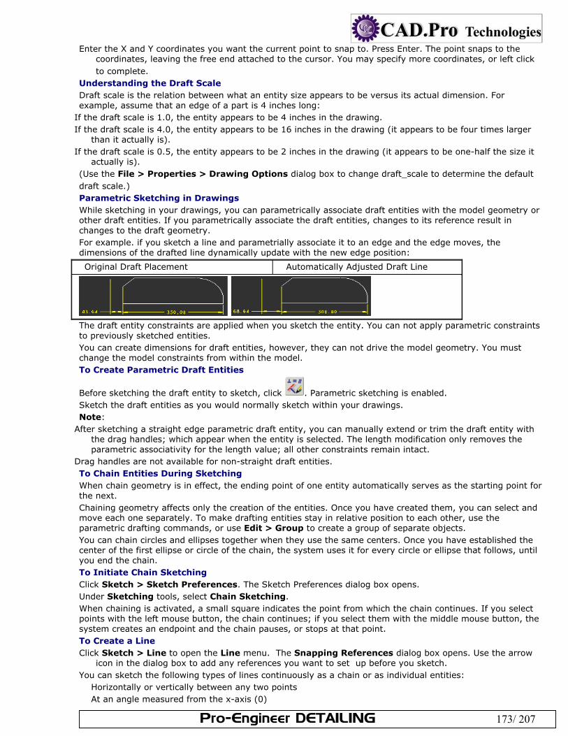
Pro-Engineer DETAILING 173/ 207
Enter the X and Y coordinates you want the current point to snap to. Press Enter. The point snaps to the coordinates, leaving the free end attached to the cursor. You may specify more coordinates, or left click to complete.
Understanding the Draft Scale Draft scale is the relation between what an entity size appears to be versus its actual dimension. For example, assume that an edge of a part is 4 inches long:
If the draft scale is 1.0, the entity appears to be 4 inches in the drawing. If the draft scale is 4.0, the entity appears to be 16 inches in the drawing (it appears to be four times larger
than it actually is). If the draft scale is 0.5, the entity appears to be 2 inches in the drawing (it appears to be one-half the size it
actually is). (Use the File > Properties > Drawing Options dialog box to change draft_scale to determine the default draft scale.) Parametric Sketching in Drawings While sketching in your drawings, you can parametrically associate draft entities with the model geometry or other draft entities. If you parametrically associate the draft entities, changes to its reference result in changes to the draft geometry. For example. if you sketch a line and parametrially associate it to an edge and the edge moves, the dimensions of the drafted line dynamically update with the new edge position:
Original Draft Placement Automatically Adjusted Draft Line
The draft entity constraints are applied when you sketch the entity. You can not apply parametric constraints to previously sketched entities. You can create dimensions for draft entities, however, they can not drive the model geometry. You must change the model constraints from within the model. To Create Parametric Draft Entities
Before sketching the draft entity to sketch, click . Parametric sketching is enabled. Sketch the draft entities as you would normally sketch within your drawings. Note:
After sketching a straight edge parametric draft entity, you can manually extend or trim the draft entity with the drag handles; which appear when the entity is selected. The length modification only removes the parametric associativity for the length value; all other constraints remain intact.
Drag handles are not available for non-straight draft entities. To Chain Entities During Sketching When chain geometry is in effect, the ending point of one entity automatically serves as the starting point for the next. Chaining geometry affects only the creation of the entities. Once you have created them, you can select and move each one separately. To make drafting entities stay in relative position to each other, use the parametric drafting commands, or use Edit > Group to create a group of separate objects. You can chain circles and ellipses together when they use the same centers. Once you have established the center of the first ellipse or circle of the chain, the system uses it for every circle or ellipse that follows, until you end the chain. To Initiate Chain Sketching Click Sketch > Sketch Preferences. The Sketch Preferences dialog box opens. Under Sketching tools, select Chain Sketching. When chaining is activated, a small square indicates the point from which the chain continues. If you select points with the left mouse button, the chain continues; if you select them with the middle mouse button, the system creates an endpoint and the chain pauses, or stops at that point. To Create a Line Click Sketch > Line to open the Line menu. The Snapping References dialog box opens. Use the arrow
icon in the dialog box to add any references you want to set up before you sketch. You can sketch the following types of lines continuously as a chain or as individual entities:
Horizontally or vertically between any two points At an angle measured from the x-axis (0)
Pro-Engineer DETAILING 174/ 207
Tangent to a curve at its second endpoint Parallel or perpendicular to a specified line Normal to a curve Tangent to an arc or a spline Tangent to two circles or splines Tangent to a curve and parallel or normal to a reference line
To Create a Circle Click Sketch > Circle or click the circle icon on the Sketcher toolbar. The Snapping References dialog box opens. Use the arrow icon in the dialog box to add any references you want to set up before you sketch. Choices for circles include:
Locating its center and defining a radius point Making it tangent to other entities Locating its center and defining a point as the tangency with another entity Making it tangent to three other entities Making it tangent to two other entities, with a specified radius Using any three points that lie on the circle To Create an Arc Click Sketch > Arc. Using the options in the Arc menu, you can create an arc by doing the following:
Selecting an endpoint that is tangent to another open entity (that is, not a circle or an ellipse) Selecting any three points that lie on the arc Using the arc center and two endpoints Using the arc center, a start point, and an angle that strokes the arc from the start point in a counterclockwise
direction Making it tangent to three other entities Making it tangent to two other entities, with a specified radius To Create a Chamfer Chamfers are beveled edges or corners. Within drawings, you can sketch chamfers at the intersection of two draft entities. The intersecting draft entities do not have to actually touch. The chamfer calculates the appropriate intersection. When you sketch a corner or edge chamfer, the existing intersection is deleted. Click Sketch > Chamfer. The CHAMFERS menu appears in the menu manager. Define how you want to dimension the chamfer:
45 x d—Create a chamfer 45 degrees from the first selected line and of dimension d along both selected lines (where d is determined by point selected on the draft entity)
d x d—Use the same dimension value along both of the selected draft entities d1 x d2—Use a different chamfer dimension for each draft entity Ang x d—Use a chamfer dimension at an angle to the draft entity Select the first draft entity to reference the chamfer. The draft entity is highlighted. Select the second draft entity to reference the chamfer. You are prompted for chamfer dimension values.
Type the appropriate dimension values for your chamfer type and click the middle-mouse button. The chamfer is created after the necessary dimensions are defined.
To Create a Fillet (2 Tangent Edges) A fillet rounds the corner of a selected intersection.
Click or Sketch > Fillet > 2 Tangent. The Select dialog box opens. Select the first fillet reference—either a point on a model edge or draft entity. Be sure to select a point close
to the desired start point of the fillet, as your selection point determines the default radius. Press CTRL and select the second fillet reference (model edge or draft entity). The reference must be tangent
to the first reference you selected. You are prompted for a radius value. By default, a radius value is provided based on your selection point locations. You can type a new radius
value or you can accept the default. Click the middle-mouse button to confirm the radius value. The fillet appears in the drawing.
To Create an Ellipse Using commands in the Sketch > ELLIPSE menu, you can create ellipses by doing the following:
Selecting the center, a point to locate the major axis, and an angle that rotates the geometry about the major axis.
Defining the length and orientation of the major axis and specifying the rotation angle about the major axis.
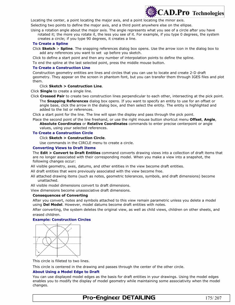
Pro-Engineer DETAILING 175/ 207
Locating the center, a point locating the major axis, and a point locating the minor axis. Selecting two points to define the major axis, and a third point anywhere else on the ellipse. Using a rotation angle about the major axis. The angle represents what you see of a circle after you have
rotated it; the more you rotate it, the less you see of it. For example, if you type 0 degrees, the system creates a circle; if you type 90 degrees, it creates a line.
To Create a Spline Click Sketch > Spline. The snapping references dialog box opens. Use the arrow icon in the dialog box to
add any references you want to set up before you sketch. Click to define a start point and then any number of interpolation points to define the spline. To end the spline at the last selected point, press the middle mouse button. To Create a Construction Line Construction geometry entities are lines and circles that you can use to locate and create 2-D draft geometry. They appear on the screen in phantom font, but you can transfer them through IGES files and plot them.
Click Sketch > Construction Line. Click Single to create a single line. Click Crossed Pair to create two construction lines perpendicular to each other, intersecting at the pick point.
The Snapping References dialog box opens. If you want to specify an entity to use for an offset or angle base, click the arrow in the dialog box, and then select the entity. The entity is highlighted and added to the list or references.
Click a start point for the line. The line will span the display and pass through the pick point. Place the second point of the line freehand, or use the right mouse button shortcut menu Offset, Angle,
Absolute Coordinates or Relative Coordinates commands to enter precise centerpoint or angle values, using your selected references.
To Create a Construction Circle Click Sketch > Construction Circle. Use commands in the CIRCLE menu to create a circle.
Converting Views to Draft Items The Edit > Convert to Draft Entities command converts drawing views into a collection of draft items that are no longer associated with their corresponding model. When you make a view into a snapshot, the following changes occur:
All visible geometry, axes, datums, and other entities in the view become draft entities. All draft entities that were previously associated with the view become free. All attached drawing items (such as notes, geometric tolerances, symbols, and draft dimensions) become
unattached. All visible model dimensions convert to draft dimensions. View dimensions become unassociative draft dimensions. Consequences of Converting After you convert, notes and symbols attached to this view remain parametric unless you delete a model using Del Model. However, model datums become draft entities with notes. After converting, the system deletes the original view, as well as child views, children on other sheets, and erased children. Example: Construction Circles
This circle is filleted to two lines.
This circle is centered in the drawing and passes through the center of the other circle. About Using a Model Edge to Draft You can use displayed model edges as the basis for draft entities in your drawings. Using the model edges enables you to modify the display of model geometry while maintaining some associativity when the model changes.
Pro-Engineer DETAILING 176/ 207
As you sketch the draft entity you can erase some of the model edges that reside behind the newly created draft entities. Draft entities that use model edges are automatically related to the view. When you erase the view, all attached detail items are erased with it. However, you can use Relate View in Edit > Group to remove the draft items and make them independent of the view. To Create a Draft Entity Using a Model Edge You can convert existing model edges to draft entities, which enables you to modify the geometry display within the drawing. Any changes you make do not effect the three dimensional geometry in the model. Click Sketch > Edge > Use. The Select dialog box opens. Select the model edge to use. Press CTRL to select multiple edges. Click OK on the Select dialog box to confirm the edges you selected. The model edges are converted to draft
entities. You are prompted to erase the model edges that exist behind the newly created draft entities. Define whether or not to erase the model edges:
To erase the selected edge, click Yes. This replaces the selected edge with the drawn line. Note: Edges do not erase when the drawing display is set to wireframe or shading. To leave the selected edge, click No. The draft entity is copied separately.
Drag handles appear on the newly converted draft entities. Modify the draft entities as necessary. If you chose to erase the model edges, applicable model edges are erased when you modify the new draft entity.
To Create Offset Draft Geometry Using the Offset command, you can create offset draft geometry from other draft entities or model geometry. If the parent object is scalable, for example scalable view geometry, or if parametric sketching is enabled when you create the offset line, the new geometry updates with any changes to the parent geometry.
Click the offset icon on the Sketcher toolbar. The Menu Manager opens. Click Single Ent. to create offset lines from a single entity. Click Ent Chain to select multiple edges from which to offset. Select the entity or entities. (Hold down the Ctrl key to select more than one entity. Click OK in the confirmation window when finished.) You are prompted for the offset distance in the direction the arrow indicates. Enter the offset distance. Use a negative distance (-) to go opposite the arrow direction. The entity is copied at the offset.
To Break a Draft Entity Insert > Break. Select the entity. Indicate breaks by selecting the start point and endpoint of each break. After the system breaks a draft entity into two separate draft entities, select the first break point on either of
the two entities to start another break. To Rotate Draft Entities Click Edit > Transform > Rotate. Select the items to rotate. Click OK in the Select dialog box. The get point menu opens on the Menu
Manager. Use the Get Point menu to select a rotation center. You are prompted to enter the rotation angle in the
counterclockwise direction.
Enter the angle and press Enter. The Item is rotated. To Stretch a Draft Entity If you have created a drawn object using several unassociated lines, you can use the Stretch command to temporarily group selected objects and stretch them all in a given direction. Lines that adjoin the selected lines, but are not selected, will stretch to follow the moved lines.
Click Edit > Transform > Stretch. Drag a selection box to enclose the entities you want to move. The Menu Manager opens to the Get Point menu.
Define the translation vector by selecting the first location—the from location; then select the final destination point. The specified entities are stretched.
Note: Filled draft entities cannot be stretched. To Trim Draft Geometry
Pro-Engineer DETAILING 177/ 207
You can trim the length of draft entities to better meet a desired drawing display. Click Edit > Trim. A flyout menu appears. Define how you want to trim the draft entity:
Divide at Intersection—Create two entities from one by dividing at an intersection. Divide by Equal Segments—Divide a selected line into a number of equal sections. You are prompted for the
number of segments. If you select multiple entities, the system divides them all the same way into equal segments. After the entity divides, it highlights the break points.
Corner—Trim two entities to their intersection. Some draft entities may be shortened while others may be extended.
Bound—Trim to a specified entity or point. You first select the boundary, then the items that trim to it. Length—Trim to a specified length. You enter a length value, then select items to trim or expand to that
length. Note: The draft entity remains collinear with the model geometry it references. Increment—Trim or extend by a specified increment. Note: Type a negative value to trim the draft entity and a positive value to extend the draft entity.
Select the draft entity to trim, or extend. The drawing display updates with the draft entity modifications. Model edges are erased if an overlapping draft entity is trimmed.
Note: You can re-display erased model edges by clicking Info > Show Modified Edges. Any erased model edges highlight. Click View > Drawing Display> Edge Display to re-display the desired edges. To Change the Line Style of Draft Entities To change the line style of selected entities as well as redefine some or all line style elements such as line font, color, and line width (thickness): In the menu bar, click Format > Line Style. Click one of the following options in the LINE STYLES menu:
Modify Lines—Allows you to select draft entities whose line styles you want to modify, using the Modify Line Style dialog box.
Edit Styles—Opens the Line Style Library dialog box, from which you can create a new line style, edit an existing style, or delete a style.
Edit Fonts—Opens the Line Font Library dialog box, from which you can create a new font, edit an existing font, or delete a font.
Clear Style—Undoes the last line style change you made. To Modify the Diameter of an Arc or Circle Select the circle or arc and right-click to display the shortcut menu. Click Edit Diameter Value from the shortcut menu. Type a new diameter for the draft entity. The entity reappears at its modified value. To update any associated draft dimensions, choose Edit > Regenerate > Draft. When you modify the diameter of an arc or circle, the system does not update unassociated draft dimensions to reflect changes in the entity size. To Mirror an Entity Using the Mirror command you can create copies of draft entities, unattached symbols, and unattached notes by mirroring them about a draft line. Click Edit > Transform > Mirror. You are prompted to select the items to mirror. Select detail items to mirror; then click the middle mouse button. You are prompted to select the line to
mirror about. The line can be a drawn line or a construction line. When you select the line, the mirror copy is created opposite the original, equidistant from the center line.
To Copy and Paste Detail Items
Select the detail items you want to copy, and then click Edit > Copy. Click Paste. The Drawing Clipboard dialog box opens and contains the copied detail items. Define the translation origin point by picking a point in the Drawing Clipboard dialog box. The translation
origin point appears as a yellow square. Select the location on the drawing where you want to place the copied items. This action pastes the copied
items, with the transition point at your pick point.. To Make and Place Multiple Copies Click Edit > Transform > Translate and Copy. Select the items to copy. You are prompted for the translation vector. Click the sheet to show the first and second point of the vector. This is both the direction the copies will be
placed, and the distance between them. You are prompted for the number of copies
Pro-Engineer DETAILING 178/ 207
Enter the number of copies and press Enter. The copies are made. To Rotate and Copy Draft Entities Click Edit > Transform > Rotate and Copy . Select all of the entities to copy and translate. Click OK. Type a rotation angle for the entities and press ENTER. The system measures the angle from the horizontal
in the counterclockwise direction. Select the center point for the copy rotation using GET POINT menu commands. Type the number of copies to create and press ENTER. The system creates the copies and rotates them. The GET VECTOR Menu You can use the GET VECTOR menu for various operations, such as translating and copying draft entities. In this case, you use the GET VECTOR menu to specify the direction for translating new draft entities.
Horiz—Translates the entities along the horizontal direction. Type a value, in drawing units, to translate the entities. Positive direction is toward the right of the sheet.
Vert—Translates the entities along the vertical direction. Type a value, in drawing units, to translate the entities. Positive direction is toward the top of the drawing sheet.
Ang/Length—Translates the entities at an angle, and a specified distance in that direction, measuring the angle relative to the horizontal in the counterclockwise direction. An arrow appears showing the positive direction of translation.
From-To—Translates the entities along a vector defined by using a start point and endpoint. About Modifying Splines You can modify splines in the following ways:
Move a single point or a range of points on the spline Add points to the interior of the spline, or extend the spline by adding points to the exterior Delete points from the spline Use a deviation value to reduce the number of spline points Smooth the spline Use the spline control polygon to modify the spline To Move a Single Spline Point Select the spline, and then right-click to display the shortcut menu. Click Edit Spline from the shortcut menu. The MOD SPLINE and MOVE PNTS menus appear in the Menu
Manager. To move a single point on the spline, click Single Pnt, and then select the point you want to move. The
point and the part of the spline that is affected moves as you move the mouse pointer to another location on the screen.
Click in the new location to place the point. Click Done Modify when you are finished. To cancel the move operation, click Quit Modify. To Move a Range of Points on a Spline Select the spline, and then right-click to display the shortcut menu. Click Edit Spline from the shortcut menu. The MOD SPLINE and MOVE PNTS menus appear in the Menu
Manager. Select two spline points limiting the adjustment range. Select the point (within the adjustment range) you want to move. To place the point in a different location, click another location on the drawing window. The selected point
moves to its new location, and the part of the spline enclosed within the range adjusts accordingly. To Add Points to a Spline You can add points to the interior of a spline, or to the exterior, thus extending the spline.
Select the spline, and then right-click to display the shortcut menu. Click Edit Spline from the shortcut menu. The MOD SPLINE and MOVE PNTS menus open in the Menu Manager. In the MOD SPLINE menu, click Add Points. Interior is selected by default in the NEW POINTS menu. Do one of the following:
Click Interior and add points to the interior of the spline by selecting any location on the spline between any two existing points.
Click Exterior and extend the spline by adding points beyond its current endpoints. Select the spline endpoint to extend; then select additional points.
To Modify a Spline's Controlling Polygon
Pro-Engineer DETAILING 179/ 207
You can modify a spline by using its control polygon (the polygon that the system creates to surround the spline when you first create it). The control polygon displays in white when you choose the Control Poly command. Select the spline, and then right-click to display the shortcut menu. Click Edit Spline from the shortcut menu. The MOD SPLINE and MOVE PNTS menus open in the Menu
Manager. Click MOD SPLINE > Control Poly.
The spline’s control polygon appears in white. Spline control points appear with line segments between them on the spline. The line segments begin and end at the startpoint and endpoint of the spline, and intermediate segments remain tangent to the spline. These line segments are visual aids for modifying the shape of the spline. Note: You cannot use this command on a spline that has a tangency condition defined for one end only.
Adjust the shape of the spline by selecting a point on the control polygon and dragging it to a new location. You cannot select endpoints. The spline rubber-bands to its new shape as you move the point.
Place the control point by pressing the left mouse button. To Delete Points from a Spline Select the spline, and then right-click to display the shortcut menu. Click Edit Spline from the shortcut menu. The MOD SPLINE and MOVE PNTS menus open in the Menu
Manager. Click MOD SPLINE > Delete Points. Select a spline point to delete. Click OK, then Done Modify, when you are finished removing points.
The system redraws the spline according to the new shape created when you removed the points. Repaint the drawing to see the new spline shape.
To Decrease Spline Points Automatically Select the spline, and then right-click to display the shortcut menu. Click Edit Spline from the shortcut menu. The MOD SPLINE and MOVE PNTS menus open in the Menu
Manager. Click MOD SPLINE > Sparse. Type a deviation value to redraw the spline with fewer points. This value must be a positive number. The
system highlights the spline and tells you how many points it is going to remove. To accept the changed spline, choose Accept; to reject it, choose Reject and type a different deviation
value. (For each spline, you might need to try several different deviation values before achieving the desired result.)
To Smooth the Spline Select the spline, and then right-click to display the shortcut menu. Click Edit Spline from the shortcut menu. The MOD SPLINE and MOVE PNTS menus open in the Menu
Manager. Click MOD SPLINE > Smooth. Type the number of points to average in order to smooth the spline:
Type [1] to keep the spline as is. Type [3] to average the centermost point out of the group and one point on each side of it. Type [5] to average the centermost point in the group and two points on each side of it.
The resulting spline appears in green. To accept it, choose Accept; to reject it, choose Reject and try again with a different number of points.
About Working with Draft Cross Sections Using Edit > Fill and then Hatched or Solid in the menu bar, you can fill or hatch a closed draft shape that you are using to represent a cross section. Pro/ENGINEER defines a draft cross section boundary by a closed loop of draft geometry. When working with draft cross sections, keep in mind the following:
You can define unfilled or uncrosshatched areas within the closed loop. The system does not consider a draft cross section to be a single entity. Therefore, to place it on a layer, you
must add the line and crosshatch pattern individually. You can modify only one draft cross section at a time. You can delete either the entire cross section (with the cross-hatching or filling and boundary) or only the
cross-hatching/filling. To Create a Draft Cross Section or Filled Area
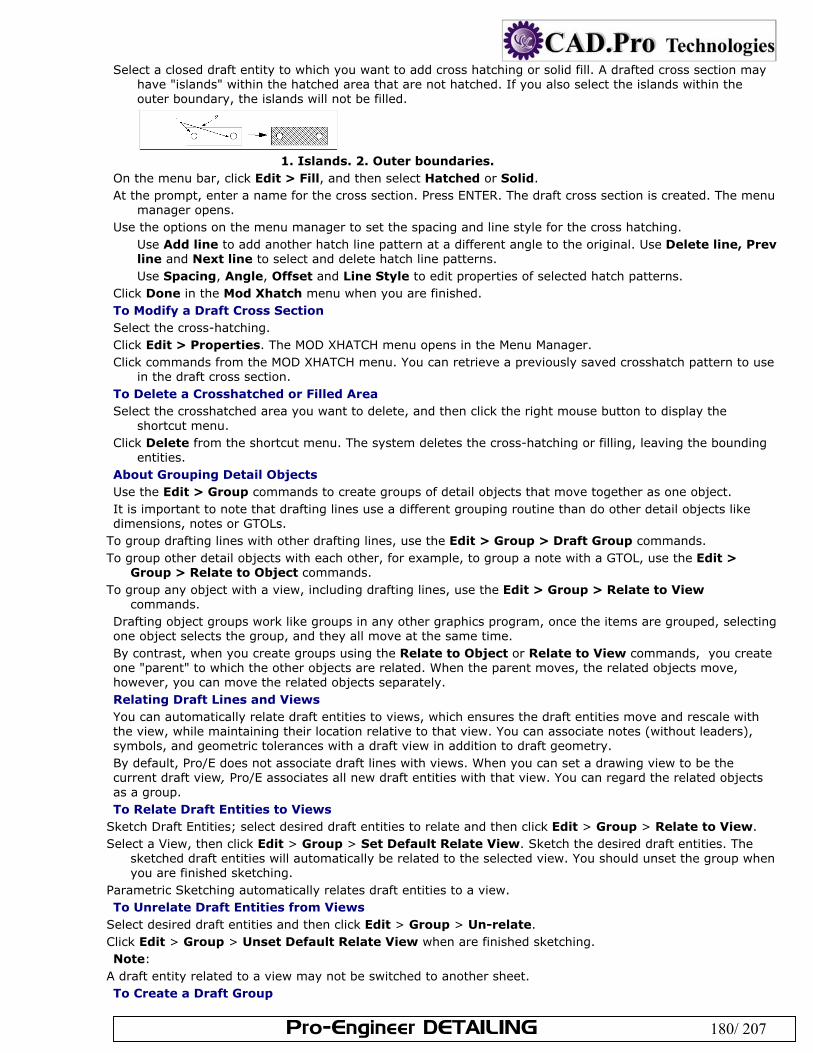
Pro-Engineer DETAILING 180/ 207
Select a closed draft entity to which you want to add cross hatching or solid fill. A drafted cross section may have "islands" within the hatched area that are not hatched. If you also select the islands within the outer boundary, the islands will not be filled.
1. Islands. 2. Outer boundaries.
On the menu bar, click Edit > Fill, and then select Hatched or Solid. At the prompt, enter a name for the cross section. Press ENTER. The draft cross section is created. The menu
manager opens. Use the options on the menu manager to set the spacing and line style for the cross hatching.
Use Add line to add another hatch line pattern at a different angle to the original. Use Delete line, Prev line and Next line to select and delete hatch line patterns. Use Spacing, Angle, Offset and Line Style to edit properties of selected hatch patterns.
Click Done in the Mod Xhatch menu when you are finished. To Modify a Draft Cross Section Select the cross-hatching. Click Edit > Properties. The MOD XHATCH menu opens in the Menu Manager. Click commands from the MOD XHATCH menu. You can retrieve a previously saved crosshatch pattern to use
in the draft cross section. To Delete a Crosshatched or Filled Area Select the crosshatched area you want to delete, and then click the right mouse button to display the
shortcut menu. Click Delete from the shortcut menu. The system deletes the cross-hatching or filling, leaving the bounding
entities. About Grouping Detail Objects Use the Edit > Group commands to create groups of detail objects that move together as one object. It is important to note that drafting lines use a different grouping routine than do other detail objects like dimensions, notes or GTOLs.
To group drafting lines with other drafting lines, use the Edit > Group > Draft Group commands. To group other detail objects with each other, for example, to group a note with a GTOL, use the Edit >
Group > Relate to Object commands. To group any object with a view, including drafting lines, use the Edit > Group > Relate to View
commands. Drafting object groups work like groups in any other graphics program, once the items are grouped, selecting one object selects the group, and they all move at the same time. By contrast, when you create groups using the Relate to Object or Relate to View commands, you create one "parent" to which the other objects are related. When the parent moves, the related objects move, however, you can move the related objects separately. Relating Draft Lines and Views You can automatically relate draft entities to views, which ensures the draft entities move and rescale with the view, while maintaining their location relative to that view. You can associate notes (without leaders), symbols, and geometric tolerances with a draft view in addition to draft geometry. By default, Pro/E does not associate draft lines with views. When you can set a drawing view to be the current draft view, Pro/E associates all new draft entities with that view. You can regard the related objects as a group. To Relate Draft Entities to Views
Sketch Draft Entities; select desired draft entities to relate and then click Edit > Group > Relate to View. Select a View, then click Edit > Group > Set Default Relate View. Sketch the desired draft entities. The
sketched draft entities will automatically be related to the selected view. You should unset the group when you are finished sketching.
Parametric Sketching automatically relates draft entities to a view. To Unrelate Draft Entities from Views
Select desired draft entities and then click Edit > Group > Un-relate. Click Edit > Group > Unset Default Relate View when are finished sketching. Note:
A draft entity related to a view may not be switched to another sheet. To Create a Draft Group
Pro-Engineer DETAILING 181/ 207
Click Edit > Group > Draft Group. The Draft Group menu opens on the Menu Manager. Click Create. You are prompted to select the draft items to add to the group. Select the items, then click the middle mouse button to complete the selection. You are prompted to name
the group Enter a name for the group and press Enter. At this point you can select draft objects for another group, or
click the middle mouse button to complete the group. To Ungroup Items from a View Select the items to remove from the group Click Edit > Group > Unrelate. The selected items are un associated from the view. To Set a Drawing View as the Current Draft View Click Edit > Group > Set Default Relate View. Select a view to be current. The system sets the selected view as the current view. To Relate Draft Items to a View Select the draft items to relate to a view Click Edit > Group > Relate to View. Click the view to relate to. The items are related to the view.
To remove an item from the related group, use Edit > Group > Unrelate To Suppress a Draft Group Click Edit > Group > Draft Group. The Draft Group menu opens on the Menu Manager. Click Suppress. The Group Access menu opens on the Menu Manager. Using the Group Access menu, do one of the following:
Click Select and select a group. Click By Name and click the group name.
The selected group is suppressed. Use the Resume command to unsuppress it. To Resume a Suppressed Group
Click Edit > Group > Draft Group. The Menu Manager opens. Click Resume.
Select the group to resume from the GROUP NAMES menu. To Ungroup a Draft Group Click Edit > Group > Draft Group. The Draft Group menu opens on the Menu Manager. Click Explode. The Group Access menu opens on the Menu Manager. Using the Group Access menu, do one of the following:
Click Select and select a group. Click By Name and click the group name.
The selected group is ungrouped. To Modify a Draft Group Click Edit > Group > Draft Group. The Draft Group menu opens on the Menu Manager. Click Edit. The Group Access menu opens on the Menu Manager. Do one of the following:
Click Select and select a group. Click By Name and click the group name.
The Edit > Group Add and Remove menus open on the Menu Manager. Use these menus to add or remove items from the selected group. Use the middle mouse button to finish.
To Group Objects with Dimension Text You can group a note, draft geometric tolerance, or symbol with dimension text so that it moves with the dimension when the dimension changes location. When you erase, redisplay, or delete the dimension, the system also does the same to all items related to it. Select the item to relate to a dimension. Click Edit > Group > Relate to Object. Select the dimension. The item is related to the dimension. Use Unrelate to remove the relationship. About Setting Draft Scale By setting a draft scale using the drawing setup file option draft_scale, you can create draft entities with a scaled size. If you set it at 0.5, any entities that you create subsequently are one-half the size that you specified. For example, creating a horizontal line of 4 inches (by selecting one endpoint and placing the second endpoint using Rel Coords with x=4 and y=0), the line measures as 2 inches on paper, but
Pro-Engineer DETAILING 182/ 207
dimensions as 4 inches. If you change the draft scale after creating and associatively dimensioning draft entities, the dimensions change. The draft scale, like other parameter values in the drawing setup file, is completely independent of a drawing scale. When the drawing size changes, the value of the draft scale does not change. The system scales the draft geometry by the proportion necessary to maintain its relative location on the sheet, and it appears to be the same size that it was before. The geometry is, in fact, a different size (because the sheet is a different size), and this is reflected by any new dimensions that you create for it; the ratio of the new dimension to the previous one is equal to the ratio of the size of the new sheet to the old one. If you set the drawing setup file option associative_dimensioning to yes (the default), when the size of dimensioned draft entities changes, the system updates the dimensions to the latest value To Scale Draft Geometry Click Edit > Transform > Rescale. Select draft geometry and dimensions to scale, and then click OK. Select the point about which to scale the entities. Type a scale value and press Enter. A number greater than 1 makes the entities larger; a number less than 1
makes them smaller. For example, a value of .25 scales the drawing to one-quarter (1/4) of the actual size of the model.
Regenerate, if necessary, to recalculate associative dimensions. About Line Fonts You can create and customize the fonts used for your two-dimensional draft lines. A line font is a pattern of dashes and spaces that are proportionate within the specified length. For example, 5 dashes and 5 spaces with a pattern length of 1 inch results in two dashes and spaces for a 2-inch line in the drawing. The same pattern definition with a 1/4-inch pattern length results in 8 dashes and spaces for a 2-inch line in the drawing. You can have a maximum of 16 dash-space combinations in a line font file. User-defined line font files, <fontname>.lsl, must reside in your local directory for you to be able to use them. When you retrieve a drawing, and the system cannot find a line font file, it displays any line that has been set with that style as solid and notifies you that it has not loaded a font file. If you have specified auxiliary font files in the drawing setup file (this occurs automatically when you create the font when that drawing is active), it identifies the font files that it could not find. Note:
You can set a default length for the line font using the line_style_length drawing setup file option. You can import and export IGES line font defintions using the iges_in_dwg_line_font (Import) and iges_out_dwg_line_font (Export) configuration options.
To Create a New Line Font You can create your own line fonts by specifying the font length and pattern. Do one of the following:
Click Format > Line Style. The LINE STYLES menu appears in the Menu Manager. Then, choose Edit Fonts from the LINE STYLES menu. Click Format > Line Font Gallery.
In either case, the Line Font Gallery dialog box opens. Click New. The New Line Font dialog box opens. Type a name in the New Name box, select an existing font to copy from the Font list, or click Select Line. Specify the font length by typing the length of one unit in the Unit Length box. Specify the font pattern by typing a series of dashes (-) and spaces ( ) in the Font Pattern box. Click OK to accept the font as currently defined. To Modify a Line Font
Do one of the following: On the menu bar, click Format > Line Style. The LINE STYLES menu appears in the Menu Manager.
Then, choose Edit Fonts from the LINE STYLES menu. On the menu bar, click Format > Line Font Gallery. In either case, the Line Font Gallery dialog box opens.
In the Line Font Gallery dialog box, select an existing font from the scrollable Fonts container. Click Modify. In the Modify Line Font dialog box, make the necessary modifications to the selected font:
Change the length by typing a new value in the Unit Length box. Change the font pattern by typing a series of dashes (-) and spaces ( ) in the Font Pattern box. The default font length can be set with line_style_length drawing setup file option. Any changes you make
to the line length will override that option.
Pro-Engineer DETAILING 183/ 207
Click OK to accept the modifications. Deleting Line Fonts You can not delete additional line font from a DTL file because fonts might also be used within drawing notes. Instead, you should replace the old font name with a different font. The integer before the font name serves as a cross-reference between the geometry and the line font, enabling you to make blanket changes to fonted geometry. For example: Within the aux_line_font drawing setup file option, replace the value of from 100 dash-1 to 100 solidfont changes all geometry that was originally dash-1 to solidfont. About Creating and Modifying Line Styles You can define and save a line style using he following elements:
a line font (a pattern of solid, dashes, spaces, and/or dots), a width for the font a color You can apply line styles to table grids, symbols, axes, draft entities, and cosmetic features. When you are in Part mode, user-defined line fonts appear in solid font. To Assign a Line Style
Select the line you want to modify. Click Format > Line Style. The Modify Line Style dialog box opens.
To assign a line style to entities, select a line style from the Style list; then click Apply. To set the line font, select a line font from the Line Font list; then click Apply. To set the width, type a value in the Width box; then click Apply (this text box is only available in Drawing
mode; it does not apply when modifying the line style of part entities in any other mode). Click Close to finish. To Create a New Line Style On the menu bar, click Format > Line Style Gallery. The Line Style Gallery dialog box opens. In the Line Style Gallery dialog box, click New. In the New Line Style dialog box, type a name in the New Name box, select an existing style to copy from
the Style list, or click Select Line. Set the line font, width, and color. To accept the new line style as currently defined click OK. To Modify a Line Style You can modify line thickness and color for individual or group selections of drafted objects. Select the object or objects to modify. Click Line Style from the right mouse button shortcut menu. The Modify Line Style dialog box opens. Use the dialog box to change the line style. Use the Copy From options to set an existing style for the
selection, or to copy a style from a line you select in the drawing. Use the Attributes options to set a combination of line font, width and color.
Click Apply, and Cancel to finish. To Specify the Default Line Style Setting
On the menu bar, click Format > Default Line Style. The SEL STYLE menu opens in the Menu Manager. From the SEL STYLE menu, choose one of these commands:
Hidden—Displays as hidden line (gray) geometry on the screen, and plots as dashed lines. Geometry—Displays as regular visible geometry (white) on the screen, and plots as solid lines. Leader—Displays as dimensions (yellow) on the screen, and plots as yellow lines. Cut Plane—Displays as white phantom lines on the screen, and plots as phantom lines with Pen 1. Phantom—Displays as gray phantom lines on the screen, and plots as phantom lines with Pen 3. Centerline—Displays as yellow centerlines on the screen, and plots as centerlines.
To Create a Custom Line Color Select the item to modify Click Properties from the right mouse button shortcut menu. On the menu bar, click Format > Line Style. The LINE STYLES menu appears in the Menu Manager. The
Modify Line Style dialog box opens. In the Modify Line Style dialog box, click Color. In the Color dialog box, click New.
Pro-Engineer DETAILING 184/ 207
In the Pro/ENGINEER Color Editor tool, using the left mouse button, define the new color. Move the RGB controls from right to left incrementally; then click on the color bar (or click OK) at the desired setting. The new color appears in the User-defined Colors box.
Click Apply. The system displays the selected item with the specified color and stores the color with the model.
To Delete a User-Defined Line Style Click Format > Line Style. The LINE STYLES menu appears in the Menu Manager. Click Edit Styles from the LINE STYLES menu. The Line Style Gallery dialog box opens.
In the Line Style Gallery dialog box, select an existing line style from the Styles list. Click Delete. In the Confirm Deletion menu, click Yes. The system removes the line style. About Markups A markup is an object that, like a set of transparent sheets on top of a drawing sheet, enables you to superimpose text and sketched entities in a variety of colors to indicate where changes may be required. A markup is an informal sketch that you can create within Pro/ENGINEER with text superimposed over any object. The basis for the markup is the object that you select to mark up. To create a markup, you use an object in the mode in which it was created:
Part (includes all objects with a .prt extension). Assembly (includes all objects with an .asm extension). Drawing Manufacturing Layout Report Diagram The object accompanies the markup file, which uses the file extension .mrk. Note: The Orientation, Model Display, and Advanced commands are not available in the Pro/ENGINEER View menu after you create a new markup object. You must orient your three-dimensional object before you create it. The system saves the orientation with the markup. Each markup is like a separate transparent sheet laid over the object and contains sketched entities and/or notes in a single color. During the markup process, the system does not change the object in any way, and saves all sketched entities and notes created in Markup mode with the markup file, not with the object. Since the driving object does not change, the system does not store it when it stores the markup. You can also create a markup for a multisheet drawing, continuing over all of the sheets. Note the following rules of operation for Markup mode:
With assemblies, the following applies: When you create an exploded view for a markup item, it does not affect the exploded status of the views
in other items. You can simultaneously see only those markup items that have the same explode status, explode
dimensions, and view orientation. You can modify explode dimensions by using Mod Explode in the ENTER MARKUP menu. The system displays three-dimensional objects with their colors as well as drawing colors. A markup file must reside in the directory of the object that the markup references. Layout dimensions appear as symbolic.
When doing a comparison with three-dimensional markup items using the Markup, Setup, and Show commands, you can toggle between Seen and Unseen only with those items that have exactly the same view as the current markup item. To Create a Markup
Click File > New. In the New dialog box, click Markup and OK. From the Markup dialog box, select or retrieve an object. Type a name for the object you are creating. The default name is your user ID. Click any of the following commands from the MARKUP menu to mark and annotate the object:
Setup—Changes the color of the markup, creates a plot of it, toggles its display, or changes to another sheet of the markup and drawing. The MRKP SETUP menu displays the following commands:
Color—Changes the color of the markup. The default markup color is red.
Pro-Engineer DETAILING 185/ 207
Show—Lists the markups in the current working area along with their color. A check mark appears next to the markup’s name and color if it is currently displayed. Choosing the markup name again removes the check mark and turns off its display. Switch Sht—lets you view and mark other sheets of the drawing. Text Height—Sets the text height before creating notes. Line Width—Sets the width of sketched entities before creating them.
Note—Places a note without a leader. Arrow—Sketches an arrow. Use the left mouse button to select the point to which the arrow points; then
select the point for the other end of the arrow. Press the middle button to abort arrow creation. Curve—Selects the points of a curve to which a spline is to be fitted. Use the left mouse button to select
the point, the middle button to stop the curve, and the right button to abort curve creation. Sketch—Sketches a curve without selecting points for it. Hold the left mouse button down to create a free
curve. Release the left button to end it. Line—Creates a line using the left mouse button. Move—Moves a note, curve, or line. Modify—Changes the note text or line width of a markup item. Delete—Deletes a markup item (note, arrow, curve, sketch, or line). Note: The Once you have chosen Note, Arrow, Curve, or Sketch, you can continue creating that type of entity until you choose another command.
About Using Drawing Overlays Using overlays, (Tools > Overlay) you can superimpose selected views or an entire sheet of one drawing over the current drawing sheet. This functionality is available for drawings, layouts, reports, and diagrams; each can reference objects of these four types, as well as formats. When working with overlays, keep in mind the following:
Overlays are read-only in the current drawing. The system updates overlays to changes in the source drawing. Overlaid views appear with all detail items. You cannot select overlays for any drawing procedure. If the size of the current drawing is different from the size of the source drawing, the overlays brought into
the current drawing maintain the same screen size (that is, they occupy the same portion of the graphics window) as they had in the source drawing.
To Create an Overlay Click Tools > Overlay. The menu manager opens. Click Add Overlay > Place Views. Position the overlay by doing one of the following:
If the source drawing has only one visible view on each of the sheets, position the origin by using the GET POINT menu to select a new location. Press the middle mouse button or choose Done to finish.
If the source drawing has more than one view on any sheet, choose Place > Views > Select Views and select the desired views. (If the view that you want to use as an overlay is on another sheet, choose Change Sheet and select the required sheet). Locate the origin of the main view by selecting a point on the screen. To accept the current position of the view origin, press the middle mouse button or choose GET POINT > Done. The system locates all of the dependent views correspondingly.
To Overlay a Drawing onto the Current Drawing Click Tools > Overlay. The Menu Manager opens. Click Add Overlay > Place Sheet. If the source drawing has only one sheet, the system confirms it and overlays the source drawing onto the
current sheet. Otherwise, if it has more than one sheet, type the appropriate sheet number. If you do not remember the required sheet number, type [?] to display the source drawing in the subwindow. Find the sheet using commands in the PLACE SHEET menu; then choose Done. The specified sheet overlays the current drawing sheet.
To Delete an Overlay Click OVERLAY DWG > Del Overlay. Do one of the following:
Click Sel Overlay to specify an overlay to delete by selecting the source drawing object from the SEL OVERLAY menu.
Click All Overlays to delete all overlays. To Move an Overlay
Pro-Engineer DETAILING 186/ 207
Click OVERLAY DWG > Move Overlay. From the SEL OVERLAY menu, select an overlay name or select it on the screen. From the SEL OVLY ITM menu, select a view. Specify the translation vector by using commands in the GET
VECTOR menu. Note: You can move an overlay by choosing OVERLAY DWG > Move Overlay; however, you cannot move overlaid sheets.
About Using Model and Draft Grids When you are working with a drawing, you can use a three-dimensional (model) grid that was defined in Part or Assembly mode or a two-dimensional grid. To use model grids, click View > Drawing Display > Model Grid, and then use the Model Grids dialog box. To use draft grids, click View > Draft Grid, and then use the GRID MODIFY menu in the Menu Manager.
To Create or Modify a Model Grid You can create a model grid in Part or Assembly mode by choosing Grid from the SET UP menu and then selecting a coordinate system to define the origin of the grid from the Model Grids dialog box. In an assembly, this coordinate system must belong to the top-level assembly. To create a model grid in Drawing mode: On the menu bar, click View > Drawing Display > Model Grid. The Model Grids dialog box opens. Use the various options on the Grids and Settings tabs to create the model grid. To modify the model grid, follow the same procedure. To Display a Model Grid in a Drawing When in a drawing, you can use commands in the DWG MDL GRID menu to display and erase the model grid. To display it, you must orient the views so that one axis of the coordinate system is normal to the screen and one axis is parallel to a drawing sheet border. Click View > Model Grid > Show Grid. The Model Grids dialog box opens. Using the Grids and Settings tabs, specify the display.
Note: If you add a view to a sheet that has a sheet grid, the view’s model has a defined grid origin, and the view is in planar orientation to this grid, the system moves the view origin to the grid origin and snaps that point to the grid point of the sheet.
To Show Model Grid Balloons You can show model grid balloons by using the Model Grids dialog box or by using the configuration options model_grid_balloon_size, model_grid_neg_prefix, model_grid_num_dig_display, and model_grid_offset. You access the Model Grids dialog box by clicking View > Model Grid.
To specify the default grid balloon size, use Setup Options in the Model Grids dialog box, or set model_grid_balloon_size.
To control the prefix of negative values in grid balloons, use the Negative Prefix option in the Model Grids dialog box, or set model_grid_neg_prefix. The default value is "-."
To set the number of digits displayed in grid balloons, use the Decimal Places option in the Model Grids dialog box, or set model_grid_num_dig_display.
To specify the offset of new model grid balloons from the drawing view, set model_grid_offset. If you set it to default (the default value), the system offsets new model grid balloons from the drawing view by twice the current model grid spacing. If you specify a number as the value, the system offsets balloons by that number of inches (not drawing units) from the view. To Erase Balloons When you erase a balloon, you blank it from the display. The balloon still exists in the background. You can redisplay the balloon using the Show/Erase dialog box, accessed by clicking View > Show and Erase in the menu bar. Select the balloon(s) you want to erase, and then right-click anywhere in the drawing window to display the
shortcut menu. Click Erase. The selected balloons display in grey, indicating that they have been erased from the display. Note: If you have erased a balloon in error, you can undo the erase operation immediately if you have not yet clicked another place in the drawing window. While the greyed-out version of the balloon still exists on the screen, right-click and select Unerase from the shortcut menu. The balloon becomes highlighted in magenta; if you click anywhere else in the drawing window, the balloon then displays in the normal system color. The Unerase option is not available if you have repainted or regenerated the display, or if you have clicked another place in the drawing window after erasing the balloon. To Erase a Model Grid from a Drawing On the menu bar, click View > Model Grid. The Model Grids dialog box opens Do one of the following:
Pro-Engineer DETAILING 187/ 207
To erase the grid by view, click View and then select the view. Click Erase. The system erases the grid but does not permanently remove it from the model.
If you want to erase a grid line, click Line and then select individual lines of the grid. Click Erase. If you want to erase by sheet, click Sheet. The system will ask you if you want to erase the grid on the
current page. Accept the default response yes. To redisplay individually erased lines, click Show > View. To Modify the Grid Size On the menu bar, click View > Model Grid. The Model Grids dialog box opens. If the system displays the grid on individual views, select the view that you want to change. Under Spacing, Type a new spacing for the grid. The system updates the grid automatically in all views in
which it appears. Modifying Model Grid Size You can set the default model grid spacing by specifying the value for the configuration file option model_grid_spacing in drawing units. You can also use the Spacing options in the Model Grids dialog box (View > Model Grid). Considerations When Using the 3-D Model Grid When using the 3-D model grid, keep in mind the following:
If you reorient a view with a grid, the system may erase the grid from the display. Therefore, before completing the procedure, you must confirm that you want to reorient the view.
When you change the view scale, the model grid adjusts to cover the entire view. The system extends the grid lines beyond a drawing view outline at a distance that equals two default grid
spaces. It uses the default grid when the model grid first appears. You can modify it later, but the extension distance does not change.
Example: Model Grid
Invalid views for model grid.
Model grid shown by view. The Model Grids Dialog Box Create and modify model grids by using the Model Grids dialog box. To access the dialog box in Drawing mode, click View > Model Grid on the menu bar. In Part or Assembly mode, click Set Up > Grids in the Menu Manager. The Grids tabbed page contains the following options:
Origin—Allows you to select the coordinate system for the grid origin. Display—Allows control over the grid display.
Show—Show the grid and grid labels by view, line, or sheet. Erase—Erase the grid and grid labels by view, line, or sheet. Show/Erase by:
View—Show or erase the grid in selected views. Line—Show or erase individual grid lines. Sheet—Show or erase the grid over the entire sheet. All relevant views snap to the grid.
Spacing—Allows you to assign the same spacing to the entire model grid or individually by axis. All—Spaces all the grid lines at the distance you define in the text box. By Axis—Spaces the grid lines on any axis individually, at the distances you define in the text box. View—Applies modifications to the model grid after you display the model grid.
Delete Grid—Deletes the grid in the current view. The Settings tabbed page contains the following options:
Setup Options—Allows you to assign various values to the following: Balloon Radius— Type in the balloon radius.
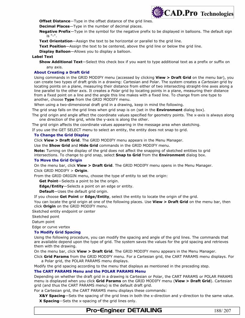
Pro-Engineer DETAILING 188/ 207
Offset Distance—Type in the offset distance of the grid lines. Decimal Places—Type in the number of decimal places. Negative Prefix—Type in the symbol for the negative prefix to be displayed in balloons. The default sign
is "-". Text Orientation—Assign the text to be horizontal or parallel to the grid line. Text Position—Assign the text to be centered, above the grid line or below the grid line. Display Balloon—Allows you to display a balloon.
Label Text Show Additional Text—Select this check box if you want to type additional text as a prefix or suffix on
any axis. About Creating a Draft Grid Using commands in the GRID MODIFY menu (accessed by clicking View > Draft Grid on the menu bar), you can create two types of draft grids in a drawing: Cartesian and Polar. The system creates a Cartesian grid by locating points on a plane, measuring their distance from either of two intersecting straight-line axes along a line parallel to the other axis. It creates a Polar grid by locating points in a plane, measuring their distance from a fixed point on a line and the angle this line makes with a fixed line. To change from one type to another, choose Type from the GRID MODIFY menu. When using a two-dimensional draft grid in a drawing, keep in mind the following.
The grid snap falls on the grid lines when grid snap is on (set in the Environment dialog box). The grid origin and angle affect the coordinate values specified for geometry points. The x-axis is always along
one direction of the grid, while the y-axis is along the other. The grid origin affects the coordinate values appearing in the message area when sketching. If you use the GET SELECT menu to select an entity, the entity does not snap to grid. To Change the Grid Display Click View > Draft Grid. The GRID MODIFY menu appears in the Menu Manager. Use the Show Grid and Hide Grid commands in the GRID MODIFY menu. Note: Turning on the display of the grid does not affect the snapping of sketched entities to grid intersections. To change to grid snap, select Snap to Grid from the Environment dialog box. To Move the Grid Origin On the menu bar, click View > Draft Grid. The GRID MODIFY menu opens in the Menu Manager. Click GRID MODIFY > Origin. From the GRID ORIGIN menu, choose the type of entity to set the origin:
Get Point—Selects a point to be the origin. Edge/Entity—Selects a point on an edge or entity. Default—Uses the default grid origin.
If you choose Get Point or Edge/Entity, select the entity to locate the origin of the grid. You can locate the grid origin at one of the following places. Use View > Draft Grid on the menu bar, then click Origin on the GRID MODIFY menu.
Sketched entity endpoint or center Sketched point Datum point Edge or curve vertex To Modify Grid Spacing Using the following procedure, you can modify the spacing and angle of the grid lines. The commands that are available depend upon the type of grid. The system saves the values for the grid spacing and retrieves them with the drawing. On the menu bar, click View > Draft Grid. The GRID MODIFY menu appears in the Menu Manager. Click Grid Params from the GRID MODIFY menu. For a Cartesian grid, the CART PARAMS menu displays. For
a Polar grid, the POLAR PARAMS menu displays. Modify the grid spacing according to the menu that displays as mentioned in the preceding step. The CART PARAMS Menu and the POLAR PARAMS Menu Depending on whether the draft grid in a drawing is Cartesian or Polar, the CART PARAMS or POLAR PARAMS menu is displayed when you click Grid Params on the GRID MODIFY menu (View > Draft Grid). Cartesian grid (and thus the CART PARAMS menu) is the default draft grid. For a Cartesian grid, the CART PARAMS menu displays these commands:
X&Y Spacing—Sets the spacing of the grid lines in both the x-direction and y-direction to the same value. X Spacing—Sets the x-spacing of the grid lines only.
Pro-Engineer DETAILING 189/ 207
Y Spacing—Sets the y-spacing of the grid lines only. Angle—Modifies the angle between the screen horizontal and the x-direction grid.
For a Polar grid, the POLAR PARAMS menu displays these commands: Ang Spacing—Sets the angular spacing between radial lines. The value you type must divide evenly into 360. Num Lines—Sets the number of radial lines to use. The angular spacing is 360 per number of lines. Rad Spacing—Modifies the spacing of the circular grid.
Angle—Modifies the angle between the horizontal and the 0-degree radial line. About Working with Drawing Parameters Using the Tools> Parameters menu you can access drawing parameter functionality for drawings and drawing formats. Drawing parameters work in the same way as do model parameters. A drawing parameter is nongraphical information you can add to a drawing. It is useful for keeping some additional information with a drawing that you may not want to include in a note. You can show the parameter value in a note by including [¶meter] in the note string. When working with drawing parameters, keep in mind the following:
The system associates parameters only with the object that is current at the time you add the parameter. You cannot use drawing parameters in relations. You can designate parameters for Pro/PDM. Drawing attributes defined in versions of Pro/E prior to Release 15.0 convert to drawing parameters
automatically. The system converts attribute names that begin with a number, but you cannot use them in notes.
To Create a Drawing Parameter Click Tools > Parameters. The Parameters dialog box opens. Use the dialog box to add a parameter to the drawing. Click the plus mark at the bottom of the dialog to add
a line for the parameter, and use the type, value and designate columns to describe the parameter properties. The types are as follows: Interger- Adds a parameter in the form of an integer (whole number). Real Number - Adds a double parameter. (Value can accommodate decimal places) String - Adds a parameter in the form of a text string as a value. Yes No - Adds a parameter with a value of yes or no. Check Designate to make the parameter visible to database management.
To Modify or Delete an Existing Drawing Parameter From the MODEL PARAMS menu, choose Modify or Delete. From the PARAMETER menu, select a drawing parameter.
To modify the parameter, type the new value. To delete it, choose Done.
To display an Information window showing all of the existing parameters and their values, choose MODEL PARAMS > Info.
Note: You also have access to Part and Assembly mode parameters while in Drawing mode. Once you delete a parameter, you cannot undo the deletion. To Get Information About Drawing Parameters Click Tools > Parameters. The Parameters dialog box opens. Click File > Export (Info) in the dialog box An information window opens and lists information about all parameters in the drawing. To Save Drawing Parameter Information as a File Click Tools > Parameters. The Parameters dialog box opens. Click File > Export Relations in the dialog box Click File > Save As in the Information window. In the Save As dialog box, navigate to the directory where you want to save the parameter information file. In the New Name box, use the default file name or type a new name. Parameter information files always
contain the extension .inf. Click OK to save the information file. System Parameters for Drawings The following table lists all system parameters available for use in drawings, classified according to functionality.
PARAMETER NAME DEFINITION
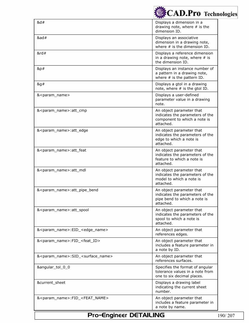
Pro-Engineer DETAILING 190/ 207
&d# Displays a dimension in a drawing note, where # is the dimension ID.
&ad# Displays an associative dimension in a drawing note, where # is the dimension ID.
&rd# Displays a reference dimension in a drawing note, where # is the dimension ID.
&p# Displays an instance number of a pattern in a drawing note, where # is the pattern ID.
&g# Displays a gtol in a drawing note, where # is the gtol ID.
&<param_name> Displays a user-defined parameter value in a drawing note.
&<param_name>:att_cmp An object parameter that indicates the parameters of the component to which a note is attached.
&<param_name>:att_edge An object parameter that indicates the parameters of the edge to which a note is attached.
&<param_name>:att_feat An object parameter that indicates the parameters of the feature to which a note is attached.
&<param_name>:att_mdl An object parameter that indicates the parameters of the model to which a note is attached.
&<param_name>:att_pipe_bend An object parameter that indicates the parameters of the pipe bend to which a note is attached.
&<param_name>:att_spool An object parameter that indicates the parameters of the spool to which a note is attached.
&<param_name>:EID_<edge_name> An object parameter that references edges.
&<param_name>:FID_<feat_ID> An object parameter that includes a feature parameter in a note by ID.
&<param_name>:SID_<surface_name> An object parameter that references surfaces.
&angular_tol_0_0 Specifies the format of angular tolerance values in a note from one to six decimal places.
¤t_sheet Displays a drawing label indicating the current sheet number.
&<param_name>:FID_<FEAT_NAME> An object parameter that includes a feature parameter in a note by name.
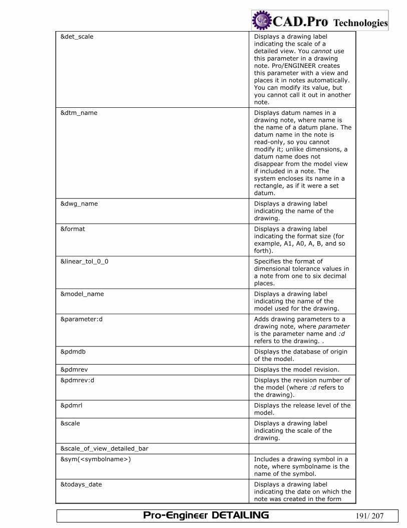
Pro-Engineer DETAILING 191/ 207
&det_scale Displays a drawing label indicating the scale of a detailed view. You cannot use this parameter in a drawing note. Pro/ENGINEER creates this parameter with a view and places it in notes automatically. You can modify its value, but you cannot call it out in another note.
&dtm_name Displays datum names in a drawing note, where name is the name of a datum plane. The datum name in the note is read-only, so you cannot modify it; unlike dimensions, a datum name does not disappear from the model view if included in a note. The system encloses its name in a rectangle, as if it were a set datum.
&dwg_name Displays a drawing label indicating the name of the drawing.
&format Displays a drawing label indicating the format size (for example, A1, A0, A, B, and so forth).
&linear_tol_0_0 Specifies the format of dimensional tolerance values in a note from one to six decimal places.
&model_name Displays a drawing label indicating the name of the model used for the drawing.
¶meter:d Adds drawing parameters to a drawing note, where parameter is the parameter name and :d refers to the drawing. .
&pdmdb Displays the database of origin of the model.
&pdmrev Displays the model revision.
&pdmrev:d Displays the revision number of the model (where :d refers to the drawing).
&pdmrl Displays the release level of the model.
&scale Displays a drawing label indicating the scale of the drawing.
&scale_of_view_detailed_bar
&sym(<symbolname>) Includes a drawing symbol in a note, where symbolname is the name of the symbol.
&todays_date Displays a drawing label indicating the date on which the note was created in the form
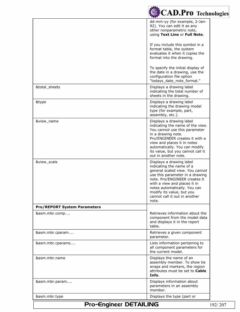
Pro-Engineer DETAILING 192/ 207
dd-mm-yy (for example, 2-Jan-92). You can edit it as any other nonparametric note, using Text Line or Full Note. If you include this symbol in a format table, the system evaluates it when it copies the format into the drawing. To specify the initial display of the date in a drawing, use the configuration file option "todays_date_note_format."
&total_sheets Displays a drawing label indicating the total number of sheets in the drawing.
&type Displays a drawing label indicating the drawing model type (for example, part, assembly, etc.).
&view_name Displays a drawing label indicating the name of the view. You cannot use this parameter in a drawing note. Pro/ENGINEER creates it with a view and places it in notes automatically. You can modify its value, but you cannot call it out in another note.
&view_scale Displays a drawing label indicating the name of a general scaled view. You cannot use this parameter in a drawing note. Pro/ENGINEER creates it with a view and places it in notes automatically. You can modify its value, but you cannot call it out in another note.
Pro/REPORT System Parameters
&asm.mbr.comp.... Retrieves information about the component from the model data and displays it in the report table.
&asm.mbr.cparam.... Retrieves a given component parameter.
&asm.mbr.cparams.... Lists information pertaining to all component parameters for the current model.
&asm.mbr.name Displays the name of an assembly member. To show tie wraps and markers, the region attributes must be set to Cable Info.
&asm.mbr.param.... Displays information about parameters in an assembly member.
&asm.mbr.type Displays the type (part or
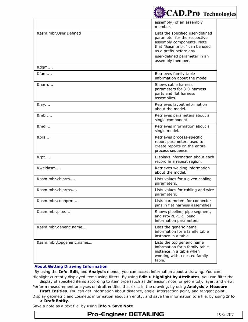
Pro-Engineer DETAILING 193/ 207
assembly) of an assembly member.
&asm.mbr.User Defined Lists the specified user-defined parameter for the respective assembly components. Note that "&asm.mbr." can be used as a prefix before any user-defined parameter in an assembly member.
&dgm....
&fam.... Retrieves family table information about the model.
&harn.... Shows cable harness parameters for 3-D harness parts and flat harness assemblies.
&lay.... Retrieves layout information about the model.
&mbr.... Retrieves parameters about a single component.
&mdl.... Retrieves information about a single model.
&prs.... Retrieves process-specific report parameters used to create reports on the entire process sequence.
&rpt.... Displays information about each record in a repeat region.
&weldasm.... Retrieves welding information about the model.
&asm.mbr.cblprm.... Lists values for a given cabling parameters.
&asm.mbr.cblprms.... Lists values for cabling and wire parameters.
&asm.mbr.connprm.... Lists parameters for connector pins in flat harness assemblies.
&asm.mbr.pipe.... Shows pipeline, pipe segment, and Pro/REPORT bend information parameters.
&asm.mbr.generic.name…. Lists the generic name information for a family table instance in a table.
&asm.mbr.topgeneric.name…. Lists the top generic name information for a family table instance in a table when working with a nested family table.
About Getting Drawing Information By using the Info, Edit, and Analysis menus, you can access information about a drawing. You can:
Highlight currently displayed items using filters. By using Edit > Highlight by Attributes, you can filter the display of specified items according to item type (such as dimension, note, or geom tol), layer, and view.
Perform measurement analyses on draft entities that exist in the drawing, by using Analysis > Measure Draft Entities. You can get information about distance, angle, intersection point, and tangent point.
Display geometric and cosmetic information about an entity, and save the information to a file, by using Info > Draft Entity.
Save a note as a text file, by using Info > Save Note.
Pro-Engineer DETAILING 194/ 207
Display the grid angle and spacing values, by using Info > Draft Grid. Obtain information about out-of-date displays in the drawing, by using Info > Check Display Status. You
can save the information to a file and select a recommended action to update the drawing (such as repainting and regenerating).
Obtain information about why a template failed when you attempted to open it, by using Info > Template Errors.
To Get Information About Draft Entities Use the following procedure to obtain cosmetic and geometric information about a selected draft entity, and to save the information on the screen or to a file. Click Info > Draft Entity. Select a draft entity.
An Information window appears containing information about the selected draft entity. To save the information on screen or to a file, click File > Save As. To Display Drawing Grid Information Use this procedure to display the grid angle and spacing values for a grid in a drawing.
Click Info > Draft Grid. The angle and spacing values for the grid are displayed in the message area. To Get Information About Drawing Template Failures Use this procedure to obtain information about why a drawing template failed when you attempted to open it.
Click Info > Template Errors. An Information window opens displaying the errors encountered when you attempted to open the template. To Highlight Items by Type and Attributes Use this procedure to highlight displayed items on the current sheet, using the type and attributes filters provided in the Highlight by Attributes dialog box. Click Edit > Highlight by Attributes. The Highlight by Attributes dialog box opens. Under Item Type, select the types of items you want to highlight. Under Owner Model:
To highlight items that were created in the drawing (but not in the associated model or models), select The drawing.
To highlight items that were created in the current model, and shown in the drawing, select A 3D model. In a multimodel drawing, the system highlights only items that were created for the current model.
Both options are selected by default. Under On Layer, select one of the following options:
Any or none—Highlights the specified items, whether or not they exist on a layer. At least one—Highlights only specified items that exist on at least one layer. Items that are not on any
layer are not highlighted. Selected and Select Layers—Highlights only specified items that are on the layers you specify.
Under Dimension Type, select the attributes of the type of dimensions you want to highlight. Owned by a model—Highlights dimensions that were created and reside in the associated model or
models (such as assembly and feature dimensions). In multimodel drawings, all dimensions that reside in all associated models are highlighted.
Created and associative—Highlights dimensions that were created in the drawing and are associative; that is, they update when the referenced entity is regenerated (resized).
Note: If you have set the drawing setup file option associative_dimensioning to no, this option is disabled.
Created but non-associative—Highlights dimensions that were created in the drawing, but are non-associative; that is, they do not update when the referenced entity is regenerated.
Under Displayed in View, select Any to display all items of the specified type in any and all views. Select Selected or click Select View to select a view in which to display the items, using the GET SELECT menu.
Click Highlight to highlight the specified items. The items are highlighted in magenta. Click Close to close the dialog box.
To Get Information About Out-of-Date Displays Click Info > Check Display Status. An Information window appears displaying the sheet number, view ID,
view name, any information about missing display status, and the recommended action to update the drawing.
To save the information to a file, click File > Save As in the Information window.
Pro-Engineer DETAILING 195/ 207
To Perform Measurement Analyses on Draft Entities Click Analysis > Measure Draft Entities. The Draft Measure dialog box opens, and the GET SELECT
menu appears. In the Type list, select the type of draft to measure (Distance, Angle, Intersection Point, or Tangent
Point). Under From and To, select the first and second entities to measure.
Note: To redisplay the GET SELECT menu, click the Select button . If you selected Angle, you can select Use horizontal to calculate the angle, instead of selecting a second
entity. Click Compute. The computations appear under Results. The results include Angle, Distance, Intersection
Point, and Tangent point. Click Compute to perform another analysis, and Info to display the results in an Information window. Click Close to remove the Draft Measure dialog box. To Save a Drawing Note as a File Use the following procedure to save drawing notes as .txt files. Select the note you want to save. Click Info > Save Note from the right mouse button shortcut menu. Enter a name for the file on the Pro/E prompt line. The note is saved in your working directory by default.
Alternately you can enter an absolute path to the file. About Importing Draft Data from External Applications You can add draft entities to a Pro/ENGINEER drawing if you have a license for Pro/DETAIL or Pro/INTERFACE. If you have a license for Pro/DETAIL, you can import the following file types:
Drawing (*.drw) Report (*.rep) IGES (*.igs, *.iges) SET (*.set) DXF (*.dxf) STEP (*stp, *.step) CGM (*.cgm) DWG (*.dwg) Parasolid (x_t, xmt_txt, x_b, xmt_bin, x_n, xmt_neu, xmt) Adobe Illustrator (*.ai) Stheno (*.tsh) Medusa You can create a group of entities which maintain their group association through an IGES export. Sheets are exported one at a time. You must create a file for each sheet. The drawing filename is appended with the sheet number used in the new file name. Imported objects are placed as non-associated draft items. If you have a license for Pro/INTERFACE, you can import the same files, but you cannot modify the entities if you do not have Pro/DETAIL. To Export to External Formats You can export a drawing to a data file in the following formats:
IGES (.igs) CADRA (.igs) SET (.set) CGM (.cgm)
DXF, (.dxf) DWG, .(dwg) STEP (.stp) Medusa (.she)
Sheets are exported one at a time. You must create a file for each sheet. The drawing filename is appended with the sheet number as the new file name. Click File > Save A Copy. The Save a Copy dialog box opens. Under New Name, enter the desired new file name. From the Type list, select the desired file type. Click OK. To Import External Formats Imported objects are placed as non-associated draft items. Click Insert > Shared Data > From File. In the Open dialog box, use Look In to find the file you want to import, and then select the file.
Pro-Engineer DETAILING 196/ 207
Click OK. The file is placed on the current sheet. To Create IGES Groups To create a group of entities which maintain their group association through an IGES export: Click Tools > IGES Group. The Menu Manager opens. Click Create. Enter the IGES group name, and then select the items that you want to belong to the group. You cannot
select items from different views. When you are done selecting items, click Done. The system creates the group. To Export a Drawing as an Image File You can capture the current screen using the Save a Copy command, or you can "plot" any number of the drawing sheets to an image file using the Print command. The following types of image files are supported: JPG - Compressed file for Web viewing (Plot Only) TIFF - Detail-rich image file suitable for printing (Screen capture or Plot) PIC - A proprietary PTC format. used for file previews, picture-to-file comparisons and the Model View program. You can verify the differences between drawings using a previously saved .pic file of the sheet. To save a TIFF file of the current screen: Click File > Save a Copy. The Save a Copy dialog box opens. Under New Name, enter the desired new file name. From the Type list, select TIFF. Click OK .You prompted "Pop the current window?" Click Yes. The file is created. To plot a whole sheet (or sheets) as a TIF or JPG file: Click File > Print. The Print dialog box opens. Click Destination > Add Printer Type > TIFF or JPEG. Check To File. Click OK. The Print to File dialog box opens. Use the dialog box to name the new file. Click OK. The new image file is created. To save a sheet as a PIC file: Click File > Save a Copy. The Save a Copy dialog box opens. Under New Name, enter the desired new file name. From the Type list, select Picture (*.pic). Click OK .The file is created in the current working directory with the .pic extension. The default file name is
the name of the drawing. About OLE Objects An object linking and embedding (OLE) object is an external file (such as a document, graphics file, or video file) that was created using an external application and that can be inserted into another application (such as Pro/ENGINEER). You can create and insert supported OLE objects into a two dimensional Pro/ENGINEER file, such as a drawing, report, format file, layout, or diagram. You can insert objects into a Pro/ENGINEER drawing from the Insert Object (Insert > Object) dialog box. Pro/ENGINEER provides two methods for inserting OLE objects: linking and embedding. After you insert an object, you can edit it within the Pro/ENGINEER environment or in its separate application window outside of Pro/ENGINEER. In Pro/ENGINEER, you can insert OLE objects into the following 2-D file types:
Drawings Reports Format files Layouts Diagrams OLE Object Display OLE object creation and editing capabilities apply to Windows systems only (Windows 95, 98, 2000, and NT). On UNIX systems, only the text, lines, bounding box, and object type information are displayed. The object itself does not display. You cannot create or edit OLE objects in UNIX; you can only move or resize an object. Note: The number and type of supported OLE objects may vary, depending on the other applications installed on the system. Linking Objects
Pro-Engineer DETAILING 197/ 207
A linked object is a file created outside of, and then linked into Pro/ENGINEER. A picture, linked to the file, appears in your drawing. Any changes to the external file are reflected in your drawing and any changes that you make to the object from within Pro/ENGINEER are saved to the original object. Embedding Objects An embedded object is saved completely within a Pro/ENGINEER drawing file and contains no links to an external file. When you insert an object as embedded, Pro/ENGINEER copies the file and places it into your document. You can still activate the object from within Pro/ENGINEER using the program that created it. Any changes that are made to the original external file are not reflected in the embedded copy. You can also create a new object (one that has no external file reference) as an embedded object. New objects you create within Pro/ENGINEER are always embedded. Plotting Options for OLE Objects The OLE mechanism does not support all types of plotters that are supported by Pro/ENGINEER. Currently, only MS Plotter is applicable for printing OLE objects. When plotting a Pro/ENGINEER drawing containing an OLE object, remember to use only MS Plotter as the device, or the OLE object does not print. To Insert an OLE Object You can insert an OLE object as a linked object or as an embedded object. Use one of the procedures below to insert an OLE object. To Create a New Embedded Object within Pro/ENGINEER Click Insert > Object. The Insert Object dialog box opens. Select Create New if it is not already selected. Under Object Type, select the type of object you want to embed into your drawing.
Note: Unsupported object types may be listed. They contain a standard Microsoft icon. Click OK to close the dialog box and create your object. The object window appears on the drawing in Edit
mode. The toolbars that belong to the application that created the drawing appear in the Graphics window.
Edit the object as desired, then click anywhere outside the object window to exit Edit mode and return to Pro/ENGINEER.
To Create an Embedded Object from an External File Click Insert >Object. The Insert Object dialog box opens. Select Create from File. Do one of the following:
Under File, type in the path and file name of the file you want to embed. Click Browse to open the Browse dialog box, locate and select the file, and click OK. The file name and
path is added to the Insert Object dialog box. Clear the Link check box. Click OK to close the dialog box and create the object. The object window appears on the drawing in Edit
mode. The toolbars that belong to the application that created the drawing appear in the Graphics window.
Edit the object as desired, then click anywhere outside the object window to exit Edit mode and return to Pro/ENGINEER.
To Link an Object Click Insert > Object. The Insert Object dialog box opens. Select Create New. Under Object Type, select the type of object you want to embed into your drawing.
Note: Unsupported object types may be listed. They contain a standard Microsoft icon. Select the Link check box.
Note: Link allows you to create a linked OLE object rather than an embedded object. Pro/ENGINEER inserts a picture of the file contents into your drawing. The picture is linked to the file so that all future changes to the file are reflected in your drawing. Link is available only when you create an object from an existing file
Click OK to close the dialog box and create the object. Edit the object as necessary, then click outside of the object window to exit Edit mode and return to
Pro/ENGINEER. To Modify an Inserted OLE Object Right-click the object you want to modify. The OLE object shortcut menu appears. On the shortcut menu, click Open if you want to edit the object in its own application window, or click Edit
to modify the object within the Pro/ENGINEER environment. If you click Edit, the object opens within the Pro/ENGINEER window, and the application toolbars open below the message area.
Edit the object as desired.
Pro-Engineer DETAILING 198/ 207
If you are editing the object outside of Pro/ENGINEER, you must update Pro/ENGINEER with the changes to the object. Within the object application window, click File > Update Pro/ENGINEER.
To exit Edit mode and return to Pro/ENGINEER, do one of the following: If you are editing the object outside of Pro/ENGINEER, open the application File menu and click Close &
Return to Pro/ENGINEER, or Exit & Return to Pro/ENGINEER. If you are editing the object from within Pro/ENGINEER, click anywhere outside the object window. The
application toolbars close and the object displays as edited. To Move or Resize an OLE Object Although the graphics of an OLE object do not display on UNIX systems, you can still move or resize it just as you can on Windows systems. To Move an OLE Object Click and drag the OLE object to the desired location on the drawing. As you drag, a ghost outline of the
object window moves with the pointer. Release the mouse button. The object moves to the new location. To Resize an OLE Object Select the object, and then click and drag a bounding box. A ghost outline of the new object size displays as you move the mouse pointer. When you release the mouse button, the object resizes. About Verifying Differences Between Drawings Using the Picture command in the Pro/ENGINEER Utilities menu, you can verify the differences between two versions of a drawing. After you store a picture of the drawing, you can retrieve it as a layer over the drawing. Anything that is the same cancels out, leaving on the screen only the differences between the two. To generate a report that lists the differences between two objects, choose File > Integrate. After you have retrieved an integration project file and the difference report, source object, and target object are displayed, the INTEGRATE menu appears, listing commands for performing the integration:
Next—Move to the next item (difference) in the report. Previous—Move to the previous item (difference) in the report. Show—In the active window, highlight the entity (feature, component, and so forth) corresponding to the
current item in the difference report. (This command is accessible only if the current item belongs to the object in the current Pro/ENGINEER Window.)
Info—Open the Information window, which contains information about the current item in the difference report (model name, component number, internal ID number, part name, and parents and or children).
Action—Open the ACTION menu. When you specify an action for one occurrence of an item (feature, component, and so forth) in the report, the specified action is set automatically for that item every time it appears in the report.
The ACTION menu contains the following commands: To Merge—Mark this source item to be merged automatically into the target. To Delete—Mark this item for automatic deletion from the target. To Ignore—Ignore this item (that is, take no merge or delete action on it even though a difference is
noted). Clear—Clear all pending actions or instructions to ignore an item. Do Manual—Integrate the item manually. This involves copying the item manually from the source object
to the target object. Merged—Mark an item as "Merged" after it has been merged manually. Deleted—Mark an item as "Deleted" after it has been deleted manually. All Changes—Accept and integrate all changes to the source and target drawings. Source Changes—Accept and integrate the changes to the source drawing. Target Changes—Accept and integrate the changes to the target drawing. Unspecified—Allows the indicated action to be applied to all items that do not already have an action
assigned to them. Overwrite—Allows you to assign an action to all items, even if actions have already been assigned to the
items. The new action overwrites the existing action. Current Item—Allows you to apply an action to the current item. All Items—Allows you to apply an action to all items that can be acted on. By Type—Allows you to apply an action to items by type: DIM COSMETICS or PARAMETERS.
Execute—Perform automatically the actions specified in the ACTION column of the difference report to resolve differences between the source and target objects. Each item is marked as Merged, Deleted, or Ignored according to the action that was specified for it.
Save Report—Save the difference report in your local working area as an ASCII text file.
Pro-Engineer DETAILING 199/ 207
Merge View—Display the difference report with the items sorted in the order in which they have to be integrated to correctly resolve all the external references (for example, parents must be merged before children and children must be deleted before parents).
Diff View—(Default) Display the difference report sorted by object and, within object, by item type. This display gives a quick report of where and what the differences are.
To Compare a Drawing to a Saved Image File You can compare a drawing sheet to a previously saved .pic file of the sheet. You can compare the whole sheet or use any portion of it in magnification. Click Analysis > Compare Sheet to Picture. The File Open dialog box opens. Select the .pic file to compare. The pic file is "layered" over the drawing page. Common items are
suppressed, and any different items, either added or deleted, are shown. To return to the current drawing click Repaint. Note: To save a drawing sheet in PIC format, use the File > Save As command. Rules for Merging Drawings The following rules and restrictions apply to merging drawings or reports:
The target drawing file must be in session. A drawing or report cannot be merged into itself. The source drawing is removed from memory after it is merged. The main drawing file can contain one or more formats. Each sheet can use a different format. When a source
drawing is merged into a target drawing that has a different format, the source format is not automatically replaced. You can replace the source format after the merge.
When the source drawing to be merged contains dimensions that are the same as those of the target drawing, Pro/ENGINEER automatically removes these duplicate dimensions from the source drawing.
When files to be merged reference a different version of the same model, the latest version in memory is used for the drawing.
The source drawing and the target drawing must use the same drawing units. When the source drawing and the target drawing contain a model with the same name, even if these are
different models, the model currently in session is used in the final drawing. After a file is merged, the drawing setup file options from the target drawing override the setup options used
by the source drawing. If the source drawing contains a drawing program, it is deleted during the merge. To preserve a drawing
program, use the drawing that contains the drawing program as the target drawing.
Drawing parameters in the source drawing are deleted during the merge. To Merge Drawings Merging two drawings allows increased performance and management of large drawings. Individual Pro/ENGINEER users can work in parallel and then merge their separate drawings into a single drawing file. A source file is appended to the target file as additional sheets; for example, when you merge a two-sheet source drawing into a four-sheet drawing, the target drawing then contains six sheets. Note: Merging removes the source file from memory. If you previously saved the source file to disk, it is removed from session but still exists on disk. Click Insert > Data From File. Use the Open dialog box to select the source file to merge into the current drawing. When you select a file,
the source file is merged into the current (target) file. Select additional source files to be merged, one file at a time, to add additional sheets to the current
drawing. About Drawing Representations Using drawing representations, you can improve performance, particularly when working with multimodel large assembly drawings and drawings of complex models. Drawing representation functionality is available only with an Advanced Assembly license. A drawing representation is a series of commands that specifies a display configuration for the current drawing. You can use drawing representations to control which models and which views of a drawing the system retrieves and displays. For example, you can temporarily remove all models and views that are not necessary for current work. With drawing representation functionality you can perform the following operations:
Improve drawing retrieval time and improve drawing performance by minimizing display calculations such as view regenerations and repaints
Configure the display of a drawing so that you can work with just the drawing information that you need for current work and keep unnecessary data out of memory
Pro-Engineer DETAILING 200/ 207
Turn off the display of views that you are not working on so that the system does not calculate unnecessary display information and, in particular, does not retrieve models into session when you retrieve a drawing
Load a drawing to a particular drawing sheet, zoom location, or view center—for example, retrieve only specified sheets of a drawing without loading all the sheets and displaying every view on each sheet
To Create a Drawing Rep for the Current Drawing Click Tools > Drawing Representation. The Menu Manager opens. Click Create. The Drawing Rep Tool dialog box opens with the View Display page visible. The dialog box
automatically fills in the appropriate commands and updates the selections to the current state of the drawing. The current commands are displayed in the command list area. The View Display page can be used to configure view display.
In the Drawing Rep Tool dialog box, type a drawing representation name in the Name box or use the default.
In the Command Definition area of the dialog box, select Display or Erase to change the view display: Display—Turns on the display of specified drawing views Erase— Turns off the display of drawing views
An erased view is replaced by a green outline containing the name of the view. To prevent erased views from being highlighted, clear Highlight Erased Views in the Environment dialog box. You can switch between Display and Erase as you specify cumulative commands.
Change the selection of views: Select All to select all the views in the current drawing. Select Individual to specify a particular view in the current drawing. The selection tool is automatically
activated, and the GET SELECT menu appears, allowing you to select an on screen view. You can use Navigate Sheets to navigate to select a view on another sheet. When you select a view, its name appears in the box.
Select Sheet to specify the sheet(s) on which to apply the commands. Type the sheet numbers in the sheet box. Enter a sheet number or multiple numbers separated by a comma (1,3), or specify a range (5-12).
Specify views of a particular type by selecting Type, and then select a view name from the Type list. The Type list includes the most frequently used view types:
General Projection Detailed Auxiliary X-section Broken Partial Exploded
You can select more than one type in any applicable combination to refine the selection. For example, select Projection to select all projection views; then select X-section to specify only cross-sectional projection views. Select Individual to select an unlisted view type such as Graph, Revolved, or Of Flat Ply.
Select Model to select all views associated with the specified drawing model. Click the selection tool and select a drawing model from the list of available models (models belonging to the current drawing).
Each command that you define is listed in the command list area. When a rep is executed, all the commands are performed in sequential order, as they were entered. Control the command list as follows:
After you select an option to configure the drawing, click Add to add the command to the command list. Add has the same effect as Execute unless the Delay View Command(s) Until Execute check box is selected.
To insert a command into the command list, select a command in the list, then select an option, then click Insert. The new command is inserted into the command list above the selected command. When the Delay View Command(s) Until Execute check box is selected, Insert does not execute until you click Execute.
To delete a command from the command list, select a command and click Delete. The command is removed from the command list. When the Delay View Command(s) Until Execute check box is selected, Delete does not execute until you click Execute.
At any time, or when all the commands are listed to configure the drawing representation, click Execute. The system applies all the commands listed, in the order in which they are listed, to the current drawing. When all listed commands have been applied, Execute is not available unless Delay View Command(s) Until Execute is selected.
Pro-Engineer DETAILING 201/ 207
Click the Drawing Display tab. The Drawing Display page can be used to automatically retrieve a specific sheet, go to a previously named view, or center a specific view. It also controls the behavior of tables with repeat regions. Use the Drawing Display options to control the cosmetic components of a drawing. In the Drawing Location area of the dialog box, do one of the following:
Select from the Go to Sheet list of available sheets in the current drawing to specify the sheet where to load the drawing representation (for example, load to sheet 6 of a 10-sheet drawing). When you retrieve a drawing representation, the specified sheet of the drawing is displayed. Only specified sheets are loaded when you retrieve the drawing representation.
To specify a named pan/zoom location for the drawing, select the name of a view from the Go to Named Pan/Zoom State list. This list contains the same view names that are on the View > Saved Views list (the views that you previously defined).
When you next retrieve the drawing representation, the drawing zooms to the selected view. This allows you to make a minor change in a particular small part of the drawing without having to see the entire drawing.
Select Go to Center of View to specify the location for the drawing representation. Centering a view keeps the drawing from repainting other views. Selecting Go to Center of View automatically clears Go to Sheet and Go to Named Pan/Zoom State.
Select the view to go to from the list of views and models, or use the GET SELECT menu to select a view, and select the middle of the view. When you next retrieve the drawing representation, the drawing centers the specified view.
In the Table Preferences area, specify table control: As Is—Leaves BOM tables in their current state Frozen—Freezes BOM tables—repeat region calculations are frozen so any changes to the BOM assembly
will not be reflected in the table Updating—Updates BOM tables—repeat regions automatically calculate changes to BOM assembly
information When you have finished configuring the drawing representation, click OK to accept the commands. The
Drawing Rep menu appears. After you have created a user-defined drawing representation, the entire Drawing Rep menu appears, and you can execute, copy, redefine, or delete a drawing representation, or display information about it in a printable window.
Save the drawing. Saving the drawing also saves the drawing representation. To Create a New Drawing Rep While Opening a Drawing You can create a new drawing representation upon retrieving a drawing. This procedure lets you go straight to the Drawing Rep Tool dialog box in the No Views drawing representation state. No drawing models are retrieved, and Delay View Command(s) Until Execute is selected by default.
Note: Delay View Command(s) Until Execute is selected by default for creating a drawing representation upon retrieval. This is a safeguard against accidentally retrieving the models into session while defining the drawing representation. With Delay View Command(s) Until Execute selected, you can specify several commands to configure the rep before executing any of them. Each command is added to the command list. The commands are not executed, and the system does not retrieve data, until you click Execute. When the Delay View Command(s) Until Execute check box is cleared, each command is executed immediately.
Click File > Open. Select a drawing from the File Open dialog box (click just once to select the drawing, not to open it) and click
Open Rep. The Open Rep dialog box opens, listing the two default drawing representations, All Views and No Views.
Do not select a drawing representation, but select the Create New Drawing Rep check box, and click OK. The Drawing Rep Tool dialog box opens.
Note: Selecting Create New Drawing Rep is a convenient way to access the Drawing Rep Tool dialog box without retrieving any models. The system retrieves the selected drawing, with none of its views displayed and its tables set to frozen. The models are not retrieved into session.
To Configure a Drawing Representation You can configure a drawing representation to control view display and drawing display in the following ways:
Display or erase all views Display or erase a particular view Display or erase views of a particular type, for example, all cross-sectional views Display or erase all views associated with a particular model
Pro-Engineer DETAILING 202/ 207
Display or erase views on a specified sheet Load the drawing to a specified sheet Load the drawing to a pan/zoom state Load the drawing to the center of a specified view Set tables to frozen or updating A drawing representation is never active—it is always executed. The drawing is always in a stage of configuration and can be changed at any time. Creating a drawing representation means that you are specifying one or more commands to configure the current drawing. As you specify commands, you can apply each command to the drawing immediately, or you can define several commands and then run them at once. A delay option is provided to allow you to configure the drawing without retrieving data until the configuration is complete. The order in which you define commands is important. The system compiles a list of commands and runs them in the order in which you define them. The commands interact with each other cumulatively. For example, you can turn all views off (command #1) and then turn on all general views (command #2). Drawing representations behave differently than simplified representations in Part and Assembly modes in that if one representation is executed after another representation, the drawing will display the results of both representations. For example, you could erase all views on sheet #1; then erase views on sheet #2; and then display all views. Each command is applied and the last command, when implemented, counteracts the earlier commands. The Drawing Rep Menu Use the Drawing Rep menu commands together with the Drawing Rep Tool dialog box to create and work with a drawing representation. When you first access the menu, only the Create, Execute, and Done-Return commands are available. After you have created a drawing representation, the other commands are also available. The Drawing Rep menu contains the following commands: Create—Opens the Drawing Rep Tool dialog box and allows you to configure a drawing representation for the current drawing. The dialog box automatically fills in the appropriate commands and updates the selections to the current state of the drawing. Execute—Opens the Select Rep dialog box and allows you to select a rep to execute from the list of existing representations. Select a rep to execute, and click OK. The system executes the selected rep for the current drawing. That is, it executes the commands required to configure a drawing as defined by the drawing representation. To save the drawing representation, you must save the drawing. Copy—Copies the selected user-defined drawing representation to a new drawing representation with an updated name. Redefine—Displays the selected user-defined drawing representation in the Drawing Rep Tool dialog box so that you can modify it. Delete—Deletes the selected user-defined drawing representation. Info—Displays a printable window containing information about the selected rep.
Done-Return—Exits the Drawing Rep menu and returns to the ADV DWG OPTS menu. The Drawing Rep Tool Dialog Box The Drawing Rep Tool dialog box is divided into two pages and opens with the View Display page visible. The View Display page allows you to control view display configurations, and the Drawing Display page allows you to control sheet, pan/zoom, and table configurations. The following options are available for both pages: Name—Displays a default name for the drawing representation that you can change Navigate Sheets—Allows you to navigate through the sheets of a drawing to display the current sheet OK—Accepts all the drawing configuration settings, closes the Drawing Rep Tool dialog box, and returns to the Drawing Rep menu Execute—Executes the active command or applies all the listed commands to the drawing. When there is no active command, Execute is not available as an indication that all listed commands have been applied. Default Drawing Representations The system automatically creates two default drawing representations named All Views and No Views for all newly created drawings. To create the default drawing representations for a previously saved drawing, retrieve the drawing and save it. The All Views and No Views default drawing representations are created.
All Views—Turns on all views to display the full drawing, keeps tables updating, and resets the pan/zoom setting.
Pro-Engineer DETAILING 203/ 207
All the models are retrieved. No Views—Turns off all views on all sheets of the drawing, keeps tables frozen, and resets the pan/zoom
setting. No model is in session. You can use a No Views rep to create detail items such as notes and symbols that have no attachment to the model. You can retrieve the drawing showing only the notes and work on them without loading any models.
To Execute a Drawing Representation You can execute a new, All Views, or No Views drawing representation. An All Views rep configures the drawing to turn on all views to display the full drawing, keeps tables updating, and resets the pan/zoom setting. A No Views drawing representation configures the drawing to turn off all views on all sheets of the drawing, keeps tables frozen, and resets the pan/zoom setting. When you load the drawing, no model is loaded. Click Tools > Drawing Representations. The Menu Manager opens. Click Execute. Select the name of the drawing representation, and click OK. The system executes the selected drawing
representation. To Copy a Drawing Representation After you have saved a drawing representation, you can copy the rep and save it with different properties. Click Tools > Drawing Representation. The menu manger opens. Click Copy. The Select Rep dialog box opens, listing the saved representations. In the Select Rep dialog box, select a rep to copy from the list of existing representations, and click OK. You
can copy only user-defined representations. The system copies the selected drawing representation and opens the Drawing Rep Tool dialog box. The
drawing representation name is automatically updated, the dialog box is populated with the same commands as those of the source rep, and the current commands are displayed in the command list area.
Rename and modify the new drawing representation. To Redefine a Drawing Representation
Click Tools > Drawing Representation. The Menu Manager opens. Click Redefine. The Select Rep dialog box opens, listing the saved representations. In the Select Rep dialog box, select a rep to redefine from the list of existing representations, and click OK. You can redefine only user-defined representations. The system opens the selected rep in the Drawing Rep Tool dialog box. Redefine the selected rep.
To Delete a Drawing Representation Click Tools > Drawing Representations. The Menu Manager opens. Click Delete. The Select Rep dialog box opens, listing the saved representations. Select a rep to delete, and click OK. You can delete only user-defined representations. The system deletes the selected rep. To Obtain Information About a Drawing Representation After you have saved a drawing representation, you can obtain information on screen about the rep, using the Info command on the Drawing Rep menu
Click Tools > Drawing Representations. The Menu Manager opens Click Info. The Select Rep dialog box opens, listing the saved representations. In the Select Rep dialog box, select a rep from the list of existing representations, and click OK. An information window displays such information as the name of the drawing representation, the commands that control view display, the commands that control the loading of the drawing. Click File > Save to write the information to a file named drawingrep.inf, or choose File > Save As to write the information to a designated file.
To Execute a Drawing Representation While Retrieving a Drawing You can execute a drawing representation directly into session while retrieving a drawing, using Open Rep in the File Open dialog box. Click File > Open. Select a drawing from the File Open dialog box (click just once to select the drawing, not to open it) and click
Open Rep. The Open Rep dialog box opens, listing previously saved drawing representations and the two default drawing representations, All Views and No Views.
Select the name of the drawing representation you want to execute, and click OK.
Pro-Engineer DETAILING 204/ 207
The system retrieves the drawing and configures the drawing to the selected drawing representation state. Note: If the drawing is already in session and you close the drawing and then access the Open Rep dialog
box, clicking Cancel brings up the drawing, which defaults to its previous state (either retrieves or does not retrieve models).
Tip: Erasing Views by Menu or by Drawing Rep Tool Dialog Box The Drawing Rep Tool Erase and Display options are functionally distinct from the Erase View and Resume View menu commands so that you can prevent previously erased views from reappearing when a drawing is retrieved. When you erase a view using the Erase option in the Drawing Rep Tool, you must use the Display option in the Drawing Rep Tool to display the view again; any views that you erased using the menu command Erase View remain erased. When you erase a view using the Erase View menu command, you must use the Resume View menu command to display the view again. About Creating Drawing Programs Using the Tools > Drawing Program commands, you can create a drawing program to define how a drawing will adapt to a change in the state of its model. Changes might occur when you re-execute the model with new Pro/PROGRAM inputs, or replace it with another instance from a family of models. Typically, you can distinguish one sequence, or state, from another by the values of some of the parameters in the model. A drawing program is intended to be used to adapt a drawing to a part or assembly program. It contains logic statements that control the drawing layout and perform various detail functions. For example, a part drawing might include a detailed view of a particular feature, such as a keyway. If you suppress that feature, the system should erase that detailed view, and move the other views to fill the space. If you make a state such as no_detail_view that erases the detailed view and organizes (moves) the other views appropriately, the program queries the system to determine if the keyway is suppressed. If so, the drawing displays the no_detail_view state. If not, the drawing displays the detailed views of the model. A drawing program has two portions: states and program text. A state is a named sequence of familiar procedures, such as showing a dimension or moving a view, that you perform on a drawing to define how it should appear. It is a record of modifications that you would like to make to the drawing. To create a state, you type a name and then record various detail commands. You can play back these commands to determine what the drawing state actually does, and then edit it, if necessary. As you create a drawing, you can create additional states and delete others. You can place dimensions, dimension breaks, and dimension clips on snap lines during the creation of a drawing program state. Once you have defined the drawing states, you can create a drawing program, as shown in the preceding figure. The drawing program is a text file, embedded inside the drawing, which contains lines of text that set certain states for the drawing, depending on the values of the conditional expressions that you use. You can use IF statements, drawing parameters, and assignment statements to set previously defined drawing states. The program first searches the drawing for a drawing parameter; if it does not find a parameter, it searches the default model for a model parameter. If the drawing program recognizes the drawing parameter, it designates it with the postfix ":d" (that is, drawing_attribute:d). If it is a model parameter, it designates it with the model number.
Commands to execute a drawing state take the following form: SET STATE name_of_state. You can nest IF statements in the following form:
IF <expression> ELSE IF <expression> ELSE ENDIF.
An expression is a logical expression that you could use in a part relation. It could contain drawing attributes (as found in the SET UP menu) or the feature suppressed function (that is, FEAT_SUPPRESSED (model_name, feat_id) to determine if a feature is suppressed; and FEAT_SUPPRESSED (assembly_name, comp_id) to determine if a component is suppressed). For example:
IF FEAT_SUPPRESSED (bolt,15) SET STATE no_detail_view
In this case, the system checks to see if feature ID 15 of the model named "bolt" is suppressed. If so, it sets the state to no_detail_view; otherwise, it does nothing.
Assignment statements take the following form: var_name = expression, where var_name is a variable name Comment lines take the following form: /* This is a comment line.
Pro-Engineer DETAILING 205/ 207
Note: The words IF, ELSE, ENDIF, SET, STATE, FEAT_SUPPRESSED are reserved. You cannot use them as variable names in a drawing program. Also, if using the equal sign (=) in an IF statement, use "==". If using a statement to set a parameter value, use "=".
Example: Drawing Program Text IF FEAT _SUPPRESSED (shaft, 12) SET STATE no_detail_view
ELSE SET STATE all_detail To Create a Record of Modifications Click Tools > Drawing Program. The Menu Manager opens. Click Define States > Create State. Type the name of the state. Press Enter. Click Record Cmds. From the DWG COMMANDS menu, choose commands to move, erase, and show items in the drawing; then
save these changes (later, you can edit the state and highlight those items). To undo any of the modifications that you have made, choose EDIT STATE > Undo Cmds. The system
places the cursor on the command that you last executed, and highlights in the drawing window the item that was acted on. If it highlights a command line in red, it means that the system has undone it (the name field is not always filled in because not all items have names).
After you create the state, the system resets the drawing to its default display. Click Done to activate the state and make the changes.
The EDIT STATE Menu Record Cmds—Displays the DWG COMMANDS menu, a compound menu of possible commands and object types upon which to operate. After choosing an action and item type, you can modify items in the drawing. The following table presents those commands that you can record (marked with an "X"). In addition to those commands included in the table as not being recordable, you cannot record the following: moving leader jogs or dimension jogs; modifying the model grid; erasing, showing, and moving cross-section arrows and view notes; erasing or moving ordinate dimensions; and modifying filled draft cross sections. Play Cmds—Resets the display of the drawing to its original display (before starting the state), and plays each saved command in the state, pausing in between. You can stop playback by selecting the stop sign icon in the message area. The system skips commands that do not affect any displayed sheet. Undo Cmds—Removes commands. Displays the Undo State Commands text-tool window listing commands in the state. Layer States—Displays the DPM LAYER menu. You can blank, display, or set to normal the display status of any drawing layer. You can also leave the status unchanged. Drawing programs can only control the status of drawing layers and cannot affect model layers. Set Cur Sheet—Switches to another sheet of the drawing to modify it. You can also display another drawing sheet by choosing Window > New from the Pro/ENGINEER menu bar. This command does not affect the current state in any way.
Commands That You Can Record (marked with an "X")
DETAIL ITEMS
Move Edit Attachment
Erase Show Show View
Switch Sheet
Create
Dimensions X X X X X X
Reference Dimensions
X X X X X X
Notes X X X X X X X
Balloon Notes X X X X X X X
BOM Balloons
X X X X X
Symbols X X X X X X
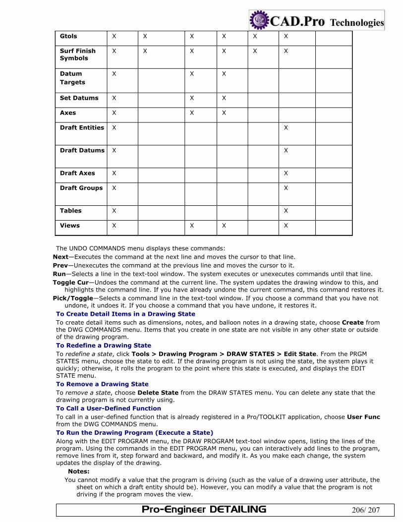
Pro-Engineer DETAILING 206/ 207
Gtols X X X X X X
Surf Finish Symbols
X X X X X X
Datum Targets
X X X
Set Datums X X X
Axes X X X
Draft Entities X X
Draft Datums X X
Draft Axes X X
Draft Groups X X
Tables X X
Views X X X X
The UNDO COMMANDS menu displays these commands:
Next—Executes the command at the next line and moves the cursor to that line. Prev—Unexecutes the command at the previous line and moves the cursor to it. Run—Selects a line in the text-tool window. The system executes or unexecutes commands until that line. Toggle Cur—Undoes the command at the current line. The system updates the drawing window to this, and
highlights the command line. If you have already undone the current command, this command restores it. Pick/Toggle—Selects a command line in the text-tool window. If you choose a command that you have not
undone, it undoes it. If you choose a command that you have undone, it restores it. To Create Detail Items in a Drawing State To create detail items such as dimensions, notes, and balloon notes in a drawing state, choose Create from the DWG COMMANDS menu. Items that you create in one state are not visible in any other state or outside of the drawing program. To Redefine a Drawing State To redefine a state, click Tools > Drawing Program > DRAW STATES > Edit State. From the PRGM STATES menu, choose the state to edit. If the drawing program is not using the state, the system plays it quickly; otherwise, it rolls the program to the point where this state is executed, and displays the EDIT STATE menu. To Remove a Drawing State To remove a state, choose Delete State from the DRAW STATES menu. You can delete any state that the drawing program is not currently using. To Call a User-Defined Function To call in a user-defined function that is already registered in a Pro/TOOLKIT application, choose User Func from the DWG COMMANDS menu. To Run the Drawing Program (Execute a State) Along with the EDIT PROGRAM menu, the DRAW PROGRAM text-tool window opens, listing the lines of the program. Using the commands in the EDIT PROGRAM menu, you can interactively add lines to the program, remove lines from it, step forward and backward, and modify it. As you make each change, the system updates the display of the drawing.
Notes: You cannot modify a value that the program is driving (such as the value of a drawing user attribute, the
sheet on which a draft entity should be). However, you can modify a value that the program is not driving if the program moves the view.
Pro-Engineer DETAILING 207/ 207
If you delete an item that the drawing program controls, the system automatically removes from the state the command in the program that controls that item.
If you convert a view to a snapshot, the system removes from their states all commands in the drawing program that control the view and its subordinate items.
The drawing program can only modify the drawing, not the models of the drawing. When the program appears, the system positions the text-tool cursor after the last line executed. As you move through the program, you can change the display by choosing commands from the SET STATE menu. After you exit the DRAW PROGRAM menu, the system executes the program in its entirety and redisplays the drawing. It automatically updates the drawing program to reflect changes made to parts when you retrieve a drawing, switch to Drawing mode, or regenerate by choosing Draft from the REGENERATE menu (you can use Model only if the model changes). After you use one of the editing commands, the system reinterprets the entire text of the program, and re-executes the program up to the cursor.
If the interpreting is successful, it converts all parameter names, model names, and keywords to uppercase. In addition, the model postfix of a parameter appears automatically when needed (for example, if the drawing has more than one model).
If the interpreting is unsuccessful, the system informs you that an error has occurred and highlights the error line. It cannot execute any line that is not interpreted, so if you move the text-tool cursor into an uninterpreted area of the program, it does not execute any states and does not change the drawing. Until you correct the error, the system does not execute the program and make the changes that the program has made to the drawing.
The Edit Program Menu To create a drawing program, choose Edit Program from the DRAW PROGRAM menu. The EDIT PROGRAM menu displays the following commands:
Insert Line—Prompts you to type text lines into the program. To finish, type a carriage return. Delete Line—Deletes a range of lines from the program. Edit Line—Modifies the current line in the message area. Screen Edit—Edits the program directly in the text-tool window. File Edit—Edits the drawing program using the system editor. Set State—Displays a run-time menu of all drawing states. You can select a state from the menu, or create a
new state interactively. Next—Moves to the next executable line of the program. Prev—Backs up one line, undoing the modification that line caused to the drawing. If you get to this line by
using the Jump command, you back up to the line on which the jump was started. Run—Executes the program forward or backward until reaching a certain line. Jump—Sets the current line as a specified line number without executing any line. You can only jump to
executable lines. Switch Dim—Changes the data display to symbols or numerical values. This command does not change the
program or the drawing. Set Cur Sheet—Sets the current sheet of the drawing for display purposes. You can display another drawing
sheet by choosing Window from the Pro/ENGINEER menu bar, followed by New. This command does not change the program or the drawing.