Section 2 Hybrid System Operation - MWP
22
TOYOTA Hybrid System - Course 071 2-1 The Toyota hybrid system has two drive sources: the gasoline engine and the electric motor. The hybrid control system selects the best combination of those two power sources depending on driving conditions. • The ’01-’03 Prius uses THS (Toyota Hybrid System). • The ’04 & later Prius uses THS-II, which carries over the same basic concepts as the previous model but offers improvements to MG1 and MG2, the battery and engine. Hybrid System Components Figure 2.1 T072f002c Section 2 Hybrid System Operation Overview
Transcript of Section 2 Hybrid System Operation - MWP

TOYOTA Hybrid System - Course 071 2-1
The Toyota hybrid system has two drive sources: the gasoline engine
and the electric motor. The hybrid control system selects the best
combination of those two power sources depending on driving
conditions.
• The ’01−’03 Prius uses THS (Toyota Hybrid System).
• The ’04 & later Prius uses THS−II, which carries over the same
basic concepts as the previous model but offers improvements to
MG1 and MG2, the battery and engine.
Hybrid SystemComponents
Figure 2.1 T072f002c
Section 2
Hybrid System Operation
Overview

Section 2
2-2 TOYOTA Technical Training
Hybrid ControlSystem Diagram
Figure 2.2 T071f202c
Hybrid system components include:
• Hybrid Transaxle, consisting of MG1, MG2 and a Planetary Gear Unit
• 1NZ−FXE engine
• Inverter Assembly containing an inverter, a boost converter, a
DC−DC converter, and an A/C inverter
• HV ECU, which gathers information from the sensors and sends
calculated results to the ECM, inverter assembly, battery ECU and
skid control ECU to control the hybrid system
• Shift Position Sensor
• Accelerator Pedal Position Sensor, which converts accelerator angle
into an electrical signal
• Skid Control ECU that controls regenerative braking
• ECM
• HV Battery
• Battery ECU, which monitors the charging condition of the HV
battery and controls cooling fan operation
• Service Plug, which shuts off the circuit
• The SMR (System Main Relay) that connects and disconnects the
high−voltage power circuit
• Auxiliary Battery, which stores 12V DC for the vehicle’s control
systems
Hybrid SystemComponents

Hybrid System Operation
TOYOTA Hybrid System - Course 071 2-3
Incorrectly performed hybrid system repairs could cause electrical
shock, battery leakage or even an explosion. Be sure to perform the
following safety procedures whenever servicing the hybrid vehicle’s
high−voltage system or hybrid control system:
• Remove the key from the ignition. If the vehicle is equipped with
smart key, turn the smart key system off.
• Disconnect the negative (−) terminal of the auxiliary battery.
• Wear insulated gloves.
• Remove service plug and put it in your pocket.
• Do not make any repairs for five minutes.
If the key cannot be removed from the key slot (for instance, because of
body damage during an accident) be sure to perform the following
procedures:
• Disconnect the auxiliary battery.
• Remove the HEV fuse (20A yellow fuse in the engine compartment
junction block.) When in doubt, pull all four fuses in the fuse block.
High−voltage insulated gloves can be ordered from the Toyota SPX/OTC
SST catalog under part numbers:
Small gloves – 00002−03100−S
Medium gloves – 00002−03200−M
Large gloves – 00002−03300−L
To check the integrity of the glove’s surface, blow air into the glove and
fold the base of the glove over to seal the air inside. Then, slowly roll
the base of the glove towards the fingers.
• If the glove holds pressure, its insulating properties are intact.
• If there is an air leak, high−voltage electricity can find its way back
through that same hole and into your body! Discard the glove(s)
and start over until you have a pair of gloves that can fully protect
you from the vehicle’s high−voltage circuits.
After disabling the vehicle, power is maintained for 90 seconds in the
SRS system and for five minutes in the high−voltage electrical system.
If any of the disabling steps above cannot be performed, proceed with
caution as there is no assurance that the high−voltage electrical
system, SRS or fuel pumps are disabled. Never cut orange high−voltage
power cables or open high−voltage components.
Safety Procedures
NOTE
WARNING

Section 2
2-4 TOYOTA Technical Training
Due to circuit resistance, it takes at least five minutes before
high−voltage is discharged from the inverter circuit. Even after five
minutes have passed, the following safety precautions should be
observed:
• Before touching an orange high−voltage cable, or any other cable
that you cannot identify, use the tester to confirm that the voltage
in the cable is 12V or less.
• After removing the service plug, cover the plug connector using
rubber or vinyl tape.
• After removing a high−voltage cable, be sure to cover the terminal
using rubber or vinyl tape.
• Use insulated tools when available.
• Do not leave tools or parts (bolts, nuts, etc.) inside the cabin.
• Do not wear metallic objects. (A metallic object may cause a
short−circuit.)
Many fire departments and police stations have been trained to safely
remove hybrid vehicles from water in case of an emergency. Always call
your local fire department in this situation.
To safely handle a Prius that is fully or partially submerged in water,
disable the high−voltage electrical system and SRS airbags. Remove the
vehicle from the water. Drain the water from the vehicle if possible.
Then, follow the extrication and vehicle disable procedures below:
• Immobilize the vehicle.
• Chock the wheels and set the parking brake.
• Remove the key from the key slot.
• If equipped with smart key, use the smart cancel switch underneath
the steering column to disable the system.
• Keep the electronic key at least 16 feet (5 meters) away from
the vehicle.
• Disconnect the 12V auxiliary battery.
• Remove the HEV fuse in the engine compartment. When in doubt,
pull all four fuses in the fuse block.
WARNING
SubmergedVehicle Safety

Hybrid System Operation
TOYOTA Hybrid System - Course 071 2-5
Service Plug
(’01-’03 Prius)
Figure 2.3 T071f203c
Service Plug
(’04 & later Prius)
Figure 2.4 T071f204c
The hybrid transaxle contains:
• Motor Generator 1 (MG1) that generates electrical power.
• Motor Generator 2 (MG2) that drives the vehicle.
• A planetary gear unit that provides continuously variable gear
ratios and serves as a power splitting device.
• A reduction unit consisting of a silent chain, counter gears and final
gears.
• A standard 2−pinion differential
The ‘01−‘03 Prius uses the P111 hybrid transaxle.
The ‘04 & later Prius uses the P112 hybrid transaxle. The P112 is
based on the P111, but offers a higher RPM range, V−shaped
permanent magnets in the rotor of MG2, and a newly designed
over−modulation control system.
Hybrid Transaxle

Section 2
2-6 TOYOTA Technical Training
Hybrid Transaxle
Figure 2.5 T071f205p
The transaxle damper uses a spring coil with low torsional
characteristics. In the ’04 & later Prius, the spring rate characteristics
of the coil spring have been reduced further to improve its vibration
absorption performance and the shape of the flywheel has been
optimized for weight reduction.
Transaxle Damper
The transaxle damper, whichtransmits the drive force ofthe engine to the transaxle,
contains a torque fluctuationadsorption mechanism that
uses a dry, single platefriction material.
Figure 2.6 T071f206p
Transaxle Damper

Hybrid System Operation
TOYOTA Hybrid System - Course 071 2-7
Hybrid Transaxle ’04 Model ’03 ModelHybrid TransaxleSpecifications Transaxle Type P112 P111Specifications
The No. of Ring Gear Teeth 78 ←
Planetary Gear The No. of Pinion Gear Teeth 23 ←Planetary Gear
The No. of Sun Gear Teeth 30 ←
Differential Gear Ratio 4.113 3.905
Number of Links 72 74
Chain Drive Sprocket 36 39Chain
Driven Sprocket 35 36
Counter GearDrive Gear 30 ←
Counter GearDriven Gear 44 ←
Final GearDrive Gear 26 ←
Final GearDriven Gear 75 ←
Fluid Capacity Liters (US qts Imp qts) 3 8 (4 0 3 3) 4 6 (4 9 4 0)Fluid Capacity Liters (US qts, Imp qts) 3.8 (4.0, 3.3) 4.6 (4.9, 4.0)
Fluid TypeATF WS orequivalent
ATF Type T-IVor equivalent
Fluid Ty eequivalent or equivalent
MG1 and MG2 function as both highly efficient alternating current
synchronous generators and electric motors. MG1 and MG2 also serve
as sources of supplemental motive force that provide power assistance
to the engine as needed.
MG1 and MG2 MG1 Specifications ’04 Model ’03 ModelMG1 and MG2Specifications Itemp
Type Permanent Magnet Motor
Function Generate, Engine Starter
Maximum Voltage [V] AC 500 AC 273.6
Cooling System Water-cooled
MG2 Specifications ’04 Model ’03 Model
Item
Type Permanent Magnet Motor
Function Generate, Engine Starter
Maximum Voltage [V] AC 500 AC 273.6
Maximum Output kW (PS) / rpm 50 (68) / 1,200 ~1,540 33 (45) / 1,040 ~ 5,600
Maximum Torque N•m (kgf•m) / rpm 400 (40.8) / 0 ~ 1,200 350 (35.7) / 0 ~ 400
Cooling System Water-cooled
Figure 2.7 T071f207c
MG1 & MG2Motor Generator 1 &
Motor Generator 2

Section 2
2-8 TOYOTA Technical Training
MG1 recharges the HV battery and supplies electrical power to drive
MG2. In addition, by regulating the amount of electrical power
generated (thus varying MG1’s internal resistance and rpm), MG1
effectively controls the transaxle’s continuously variable transmission.
MG1 also serves as the engine starter.
MG2 and the engine work together to drive the wheels. The addition of
MG2’s strong torque characteristics help achieve excellent dynamic
performance, including smooth start−off and acceleration. During
regenerative braking, MG2 converts kinetic energy into electrical
energy, which is then stored in the HV battery.
Towing a damaged Prius with its front wheels on the ground may cause
MG2 to generate electricity. If that happens, the electrical insulation
could leak and cause a fire. Always tow the vehicle with the front
wheels off of the ground or on a flat bed.
The planetary gear unit is used as a power splitting device. The sun
gear is connected to MG1, the ring gear is connected to MG2, and the
planetary carrier is connected to the engine output shaft. The motive
force is transmitted from the chain drive sprocket to the reduction unit
via a silent chain.
Item Connection
Sun Gear MG1
Ring Gear MG2
Carrier Engine Output Shaft
MG1 Description
MG2 Description
NOTE
Planetary Gear Unit
Planetary GearConnection
Figure 2.8 T072f035
Hybrid System Operation
TOYOTA Hybrid System - Course 071 2-9
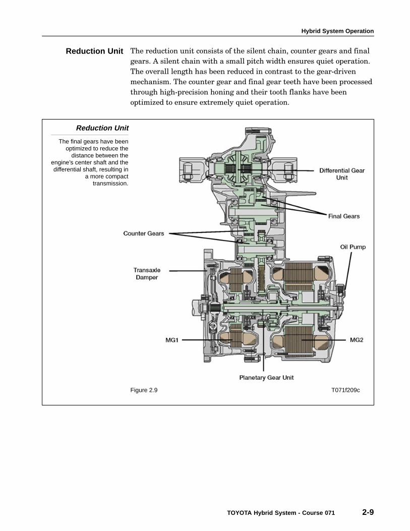
The reduction unit consists of the silent chain, counter gears and final
gears. A silent chain with a small pitch width ensures quiet operation.
The overall length has been reduced in contrast to the gear−driven
mechanism. The counter gear and final gear teeth have been processed
through high−precision honing and their tooth flanks have been
optimized to ensure extremely quiet operation.
Reduction Unit
The final gears have beenoptimized to reduce the
distance between theengine’s center shaft and thedifferential shaft, resulting in
a more compacttransmission.
Figure 2.9 T071f209c
Reduction Unit

Section 2
2-10 TOYOTA Technical Training
When three−phase alternating current is passed through the windings
of the stator coil, a rotating magnetic field is created. When the
rotation of this magnetic field is properly timed in relationship to the
rotor, the magnetic field pulls the permanent magnets housed inside
the rotor in a circle, causing the rotor to turn and creating the motor’s
torque. The generated torque is proportionate to the amount of current
passing through the stator coils and the rotational speed is controlled
by the frequency of the three−phase alternating current.
A high level of torque can be generated efficiently at all speeds by
properly controlling the rotating magnetic field and the angles of the
rotor magnets.
On the ’04 & later Prius the built−in permanent magnets have been
changed to a V−shaped structure to improve both power output and
torque.
PermanentMagnet Motor
Figure 2.10 T071f210c
PermanentMagnet Motor

Hybrid System Operation
TOYOTA Hybrid System - Course 071 2-11
Permanent MagnetStructure
The V-shaped structure ofthe magnets in the ’04 & later
model provides about50% more power than
previous models.
Figure 2.11 T071f211c
This reliable and compact sensor precisely detects the magnetic pole
position, which is essential for the control of MG1 and MG2.
The sensor’s stator contains three coils. Since the rotor is oval, the gap
between the stator and the rotor varies with the rotation of the rotor.
In addition, the HV ECU uses this sensor as an rpm sensor, calculating
the amount of positional variance within a predetermined time
interval.
Speed Sensor(Resolver) Operation
Output coils B and C areelectrically staggered
90 degrees. Because therotor is oval, the distance ofthe gap between the stator
and the rotor varies with therotation of the rotor. By
passing an alternating currentthrough coil A, output thatcorresponds to the sensor
rotor’s position is generatedby coils B and C. The
absolute position can then bedetected from the difference
between these outputs.
Figure 2.12 T071f212
Speed Sensor(Resolver)

Section 2
2-12 TOYOTA Technical Training
Inverter Assembly
(’04 & later Prius)
Figure 2.13 T071f213p
The inverter changes high−voltage direct current from the HV battery
into three−phase alternating current for MG1 and MG2. The HV ECU
controls the activation of the power transistors. In addition, the
inverter transmits information that is needed to control current, such
as the output amperage or voltage, to the HV ECU.
The inverter, MG1, and MG2, are cooled by a dedicated radiator and
coolant system that is separate from the engine coolant system. The
HV ECU controls the electric water pump for this system. In the ’04 &
later Prius, the radiator has been simplified and the space it occupies
has been optimized.
The boost converter boosts the nominal voltage of 201.6V DC that is
output by the HV battery to the maximum voltage of 500V DC. To boost
the voltage, the converter uses a boost IPM (Integrated Power Module)
with a built−in IGBT (Insulated Gate Bipolar Transistor) for switching
control, and a reactor to store the energy.
When MG1 or MG2 acts as a generator, the inverter converts the
alternating current (range of 201.6V to 500V) generated by either
motor into direct current, then the boost converter drops the voltage to
201.6V DC to charge the HV battery.
Inverter
Boost Converter(’04 & later Prius)

Hybrid System Operation
TOYOTA Hybrid System - Course 071 2-13
Inverter AssemblyDiagram
(’04 & later Prius)
Figure 2.14 T071f214c
The vehicle’s auxiliary equipment (such as lights, audio system, A/C
cooling fan, ECUs, etc.) is powered by standard 12V DC.
On the ’01−’03 Prius, the THS generator voltage is 273.6V DC. A
converter transforms the voltage from 273.6V DC to 12V DC to
recharge the auxiliary battery.
On the ’04 and later Prius, the THS−II generator outputs a nominal
voltage of 201.6V DC. The converter transforms the voltage from
201.6V DC to 12V DC to recharge the auxiliary battery.
DC/DC ConverterSystem Diagram
(’04 & later Prius)
The inverter is installed onthe underside of the inverter.
Figure 2.15 T071f215c
Converter

Section 2
2-14 TOYOTA Technical Training
The inverter assembly includes a separate inverter for the air
conditioning system that changes the HV battery’s nominal voltage of
201.6V DC into 201.6V AC to power the air conditioning system’s
electric inverter compressor.
A/C Inverter
(’04 & later Prius)
Figure 2.16 T071f216c
A/C Inverter(’04 & later Prius)

Hybrid System Operation
TOYOTA Hybrid System - Course 071 2-15
A dedicated cooling system uses a water pump to cool the inverter,
MG1 and MG2. It is separate from the engine cooling system. This
cooling system activates when the power supply is switched to IG.
Cooling System
(’04 & later Prius)
The radiator for the coolingsystem is integrated with the
radiator for the engine.
Figure 2.17 T071f217c
The HV ECU:
• Controls MG1, MG2 and the engine based on torque demand,
regenerative brake control and the HV Battery’s State of Charge
(SOC). These factors are determined by the shift position, the
degree with which the accelerator is depressed and vehicle speed.
• The HV ECU monitors HV Battery SOC and the temperature of the
HV battery, MG1 and MG2.
• To ensure reliable circuit shutdown and protect the vehicle’s
circuits from high−voltage, the HV ECU uses three relays housed in
the System Main Relay assembly to connect and disconnect the
high−voltage circuit.
• If the HV ECU detects a malfunction in the hybrid system, it will
control the system based on the data that is stored in its memory.
Cooling Systemfor Inverter, MG1
and MG2
HV ECU

Section 2
2-16 TOYOTA Technical Training
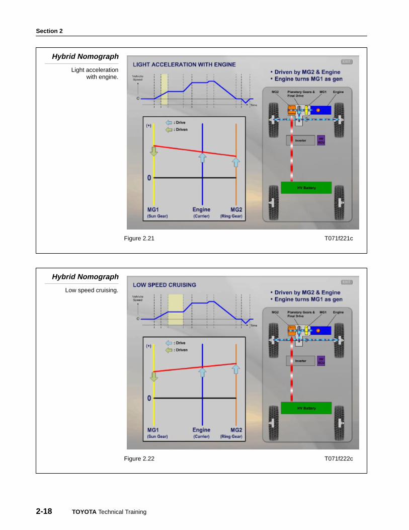
A nomograph is a kind of chart that conveys the relationship between
different sets of numbers. The hybrid operation nomographs below
convey the relationship between RPM for MG1, MG2 and the engine.
Because MG1, MG2 and the engine are mechanically connected in the
Planetary Gear Set, if one of the components changes rpm, the rpm of
the other components will be affected. So in the nomograph, the rpm
values of the 3 power sources maintain a relationship in which they are
always connected by a straight line.
Hybrid Nomograph
Ready-on.
Figure 2.18 T071f218c
Nomographs

Hybrid System Operation
TOYOTA Hybrid System - Course 071 2-17
Hybrid Nomograph
Starting out.
Figure 2.19 T071f219c
Hybrid Nomograph
Engine starting.
Figure 2.20 T071f220c
Section 2
2-18 TOYOTA Technical Training
Hybrid Nomograph
Light accelerationwith engine.
Figure 2.21 T071f221c
Hybrid Nomograph
Low speed cruising.
Figure 2.22 T071f222c

Hybrid System Operation
TOYOTA Hybrid System - Course 071 2-19
Hybrid Nomograph
Full acceleration.
Figure 2.23 T071f223c
Hybrid Nomograph
High speed cruising.
Figure 2.24 T071f224c

Section 2
2-20 TOYOTA Technical Training
Hybrid Nomograph
Max speed.
Figure 2.25 T071f225c
Hybrid Nomograph
Deceleration or braking.
Figure 2.26 T071f226c

Hybrid System Operation
TOYOTA Hybrid System - Course 071 2-21
Hybrid Nomograph
Reverse.
Figure 2.27 T071f227c
Information Codes are a three−digit supplement to HV ECU DTCs.
They provide additional information and freeze frame data to help
diagnose the vehicle’s condition. These codes can be found on the
Diagnostic Tester HV ECU menu. Use the screen flow shown below to
access the codes. For a detailed description of each Information Code,
refer to the DI section of the Repair Manual.
Using InformationCodes

Section 2
2-22 TOYOTA Technical Training
AccessingInformation Codes
Follow the screen flowto access the
Information Codes.
Figure 2.28 T071f228