SACS Import Manual - CSI Documentsdocs.csiamerica.com/manuals/sap2000/SACS Import.pdf · SACS...
23
SACS Import Manual
Transcript of SACS Import Manual - CSI Documentsdocs.csiamerica.com/manuals/sap2000/SACS Import.pdf · SACS...
SACS Import Manual
SACSImport Manual
for
ISO SAP102816M6Rev. 0Proudly developed in the United States of America October 2016

COPYRIGHT
Copyright © Computers and Structures, Inc., 1978-2016All rights reserved.
The CSI Logo® and SAP2000® are registered trademarks of Computers and Structures, Inc. Adobe® and Acrobat® are registered trademarks of Adobe Systems Incorporated. SACSTM is a trademark of Bentley Systems, Inc.
The computer program SAP2000® and all associated documentation are proprietary and copyrighted products. Worldwide rights of ownership rest with Computers and Structures, Inc. Unlicensed use of this program or reproduction of documentation in any form, without prior written authorization from Computers and Structures, Inc., is explicitly prohibited.
No part of this publication may be reproduced or distributed in any form or by any means, or stored in a database or retrieval system, without the prior explicit written permission of the publisher.
Further information and copies of this documentation may be obtained from:
Computers and Structures, Inc.www.csiamerica.com
[email protected] (for general information)[email protected] (for technical support)
DISCLAIMER
CONSIDERABLE TIME, EFFORT AND EXPENSE HAVE GONE INTO THE DEVELOPMENT AND TESTING OF THIS SOFTWARE. HOWEVER, THE USER ACCEPTS AND UNDERSTANDS THAT NO WARRANTY IS EXPRESSED OR IMPLIED BY THE DEVELOPERS OR THE DISTRIBUTORS ON THE ACCURACY OR THE RELIABILITY OF THIS PRODUCT.
THIS PRODUCT IS A PRACTICAL AND POWERFUL TOOL FOR STRUCTURAL DESIGN. HOWEVER, THE USER MUST EXPLICITLY UNDERSTAND THE BASIC ASSUMPTIONS OF THE SOFTWARE MODELING, ANALYSIS, AND DESIGN ALGORITHMS AND COMPENSATE FOR THE ASPECTS THAT ARE NOT ADDRESSED.
THE INFORMATION PRODUCED BY THE SOFTWARE MUST BE CHECKED BY A QUALIFIED AND EXPERIENCED ENGINEER. THE ENGINEER MUST INDEPENDENTLY VERIFY THE RESULTS AND TAKE PROFESSIONAL RESPONSIBILITY FOR THE INFORMATION THAT IS USED.
Contents
1 Introduction
1.1 Import a SACS File 1
1.2 Review Import Log 2
2 Read the SACS Input File
2.1 Input File Format 1
2.2 “Lines” Read 1
3 Translate the Model to SAP2000
3.1 SACS IV 13.1.1 OPTIONS “Line” 13.1.2 SECT “Line” 23.1.3 GRUP “Line” 33.1.4 MEMBER “Line” 43.1.5 MEMBER OFFSETS “Line” 53.1.6 PGRUP “Line” 63.1.7 PLATE “Line” 73.1.8 JOINT “Line” 83.1.9 JOINT PERSET “Line” 93.1.10 JOINT ELASTI “Line” 93.1.11 LOADCN “Line” 103.1.12 LOAD UNIF “Line” 103.1.13 LOAD DMOM “Line” 113.1.14 LOAD CONC “Line” 113.1.15 LOAD MOMT “Line” 123.1.16 LOAD JOIN “Line” 133.1.17 LCOMB “Line” 13
i
1 Introduction
This manual describes the capabilities for importing SACS models into SAP2000®. SACS Ver-sion 5.6 files are currently handled. Models from other versions should also import, although this has not been thoroughly tested.
It is important to read this entire manual before importing a SACS model in order to become fa-miliar with any limitations of the import or assumptions that have been made.
The process of importing a SACS model is broken into two main steps, namely
reading the contents of the SACS input file
translating the SACS model contents into a SAP2000 model
Chapter 2 of this manual describes the first step of reading the SACS input file, while Chapter 3 describes in detail the translation of the SACS model into a SAP2000 model.
1.1 Import a SACS File
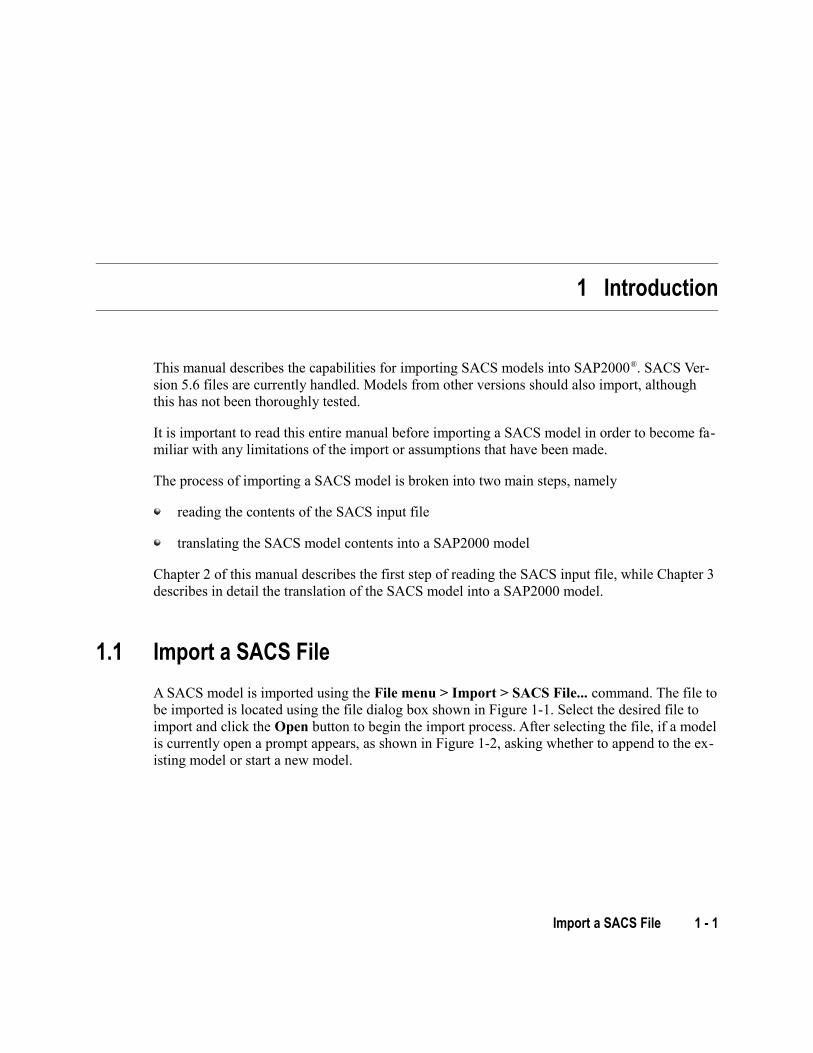
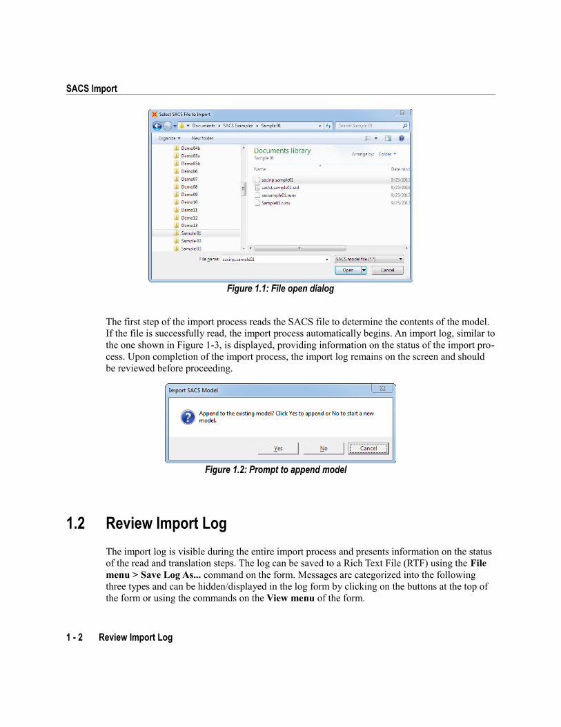
A SACS model is imported using the File menu > Import > SACS File... command. The file to be imported is located using the file dialog box shown in Figure 1-1. Select the desired file to import and click the Open button to begin the import process. After selecting the file, if a model is currently open a prompt appears, as shown in Figure 1-2, asking whether to append to the ex-isting model or start a new model.
Import a SACS File 1 - 1
SACS Import
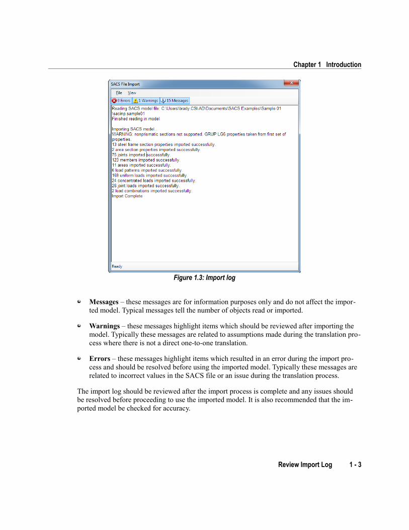
The first step of the import process reads the SACS file to determine the contents of the model. If the file is successfully read, the import process automatically begins. An import log, similar to the one shown in Figure 1-3, is displayed, providing information on the status of the import pro-cess. Upon completion of the import process, the import log remains on the screen and should be reviewed before proceeding.
1.2 Review Import Log
The import log is visible during the entire import process and presents information on the status of the read and translation steps. The log can be saved to a Rich Text File (RTF) using the File menu > Save Log As... command on the form. Messages are categorized into the following three types and can be hidden/displayed in the log form by clicking on the buttons at the top of the form or using the commands on the View menu of the form.
1 - 2 Review Import Log
Figure 1.2: Prompt to append model
Figure 1.1: File open dialog
Chapter 1 Introduction
Messages – these messages are for information purposes only and do not affect the impor-ted model. Typical messages tell the number of objects read or imported.
Warnings – these messages highlight items which should be reviewed after importing the model. Typically these messages are related to assumptions made during the translation pro-cess where there is not a direct one-to-one translation.
Errors – these messages highlight items which resulted in an error during the import pro-cess and should be resolved before using the imported model. Typically these messages are related to incorrect values in the SACS file or an issue during the translation process.
The import log should be reviewed after the import process is complete and any issues should be resolved before proceeding to use the imported model. It is also recommended that the im-ported model be checked for accuracy.
Review Import Log 1 - 3
Figure 1.3: Import log
2 Read the SACS Input File
This chapter describes the process of reading the SACS input file which is the first step in the import process.
2.1 Input File Format
The SACS input file is composed of “lines”. Each input line is read individually and the content parsed into appropriate fields. The following sections define which “lines” are read during the import.
2.2 “Lines” Read
The following list of “lines” are read in during the import process. Details of the translation of the “line” data are provided in the following chapters. It is recommended that the following chapters describing the translation be reviewed as some items on the “lines” may not be trans-lated. For further information about any of the “lines”, please refer to the SACS User's Manual.
SACS IV
OPTIONS Input, analysis, and output options
SECT Member cross section properties
GRUP Material and other properties
MEMBER Member connectivities
MEMB2 Additional member data
MEMBER OFFSETS Member offsets
“Lines” Read 2 - 1
SACS Import
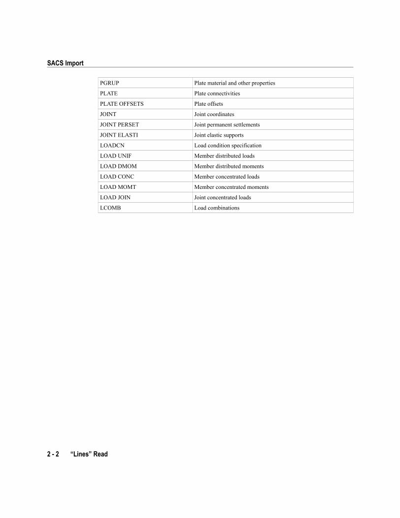
PGRUP Plate material and other properties
PLATE Plate connectivities
PLATE OFFSETS Plate offsets
JOINT Joint coordinates
JOINT PERSET Joint permanent settlements
JOINT ELASTI Joint elastic supports
LOADCN Load condition specification
LOAD UNIF Member distributed loads
LOAD DMOM Member distributed moments
LOAD CONC Member concentrated loads
LOAD MOMT Member concentrated moments
LOAD JOIN Joint concentrated loads
LCOMB Load combinations
2 - 2 “Lines” Read
3 Translate the Model to SAP2000
This chapter describes the translation of the SACS model to SAP2000. Only the “lines” defined in Chapter 3 as being read in are discussed in this chapter. Note that not all features on each “line” are imported, so it is important to review the following sections to determine what parts of the model are imported.
For further information about a particular feature or capability of SAP2000, refer to the SAP2000 manuals available from the Help menu > Documentation... command or to the inter-active help, available from the Help menu > Contents and Index... command.
3.1 SACS IV
This section describes the imported “lines” from the SACS IV input file.
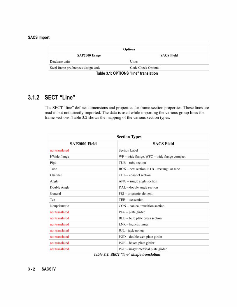
3.1.1 OPTIONS “Line”
The OPTIONS “line” provides input, analysis, and output options. Only the units and code check options are currently read and used to define the database units and steel frame design code during translation.
SACS IV 3 - 1
SACS Import
Options
SAP2000 Usage SACS Field
Database units Units
Steel frame preferences design code Code Check Options
Table 3.1: OPTIONS "line" translation
3.1.2 SECT “Line”
The SECT “line” defines dimensions and properties for frame section properties. These lines are read in but not directly imported. The data is used while importing the various group lines for frame sections. Table 3.2 shows the mapping of the various section types.
Section Types
SAP2000 Field SACS Field
not translated Section Label
I/Wide flange WF – wide flange, WFC – wide flange compact
Pipe TUB – tube section
Tube BOX – box section, RTB – rectangular tube
Channel CHL – channel section
Angle ANG – single angle section
Double Angle DAL – double angle section
General PRI – prismatic element
Tee TEE – tee section
Nonprismatic CON – conical transition section
not translated PLG – plate girder
not translated BLB – bulb plate cross section
not translated LNR – launch runner
not translated JUL – jack-up leg
not translated PGD – double web plate girder
not translated PGB – boxed plate girder
not translated PGU – unsymmetrical plate girder
Table 3.2: SECT “line” shape translation
3 - 2 SACS IV
Chapter 3 Translate the Model to SAP2000
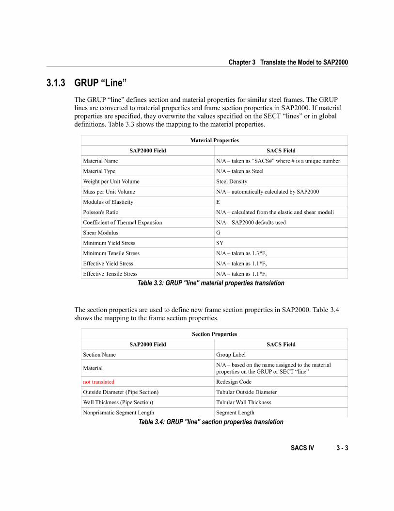
3.1.3 GRUP “Line”
The GRUP “line” defines section and material properties for similar steel frames. The GRUP lines are converted to material properties and frame section properties in SAP2000. If material properties are specified, they overwrite the values specified on the SECT “lines” or in global definitions. Table 3.3 shows the mapping to the material properties.
Material Properties
SAP2000 Field SACS Field
Material Name N/A – taken as “SACS#” where # is a unique number
Material Type N/A – taken as Steel
Weight per Unit Volume Steel Density
Mass per Unit Volume N/A – automatically calculated by SAP2000
Modulus of Elasticity E
Poisson's Ratio N/A – calculated from the elastic and shear moduli
Coefficient of Thermal Expansion N/A – SAP2000 defaults used
Shear Modulus G
Minimum Yield Stress SY
Minimum Tensile Stress N/A – taken as 1.3*Fy
Effective Yield Stress N/A – taken as 1.1*Fy
Effective Tensile Stress N/A – taken as 1.1*Fu
Table 3.3: GRUP "line" material properties translation
The section properties are used to define new frame section properties in SAP2000. Table 3.4 shows the mapping to the frame section properties.
Section Properties
SAP2000 Field SACS Field
Section Name Group Label
MaterialN/A – based on the name assigned to the material properties on the GRUP or SECT “line”
not translated Redesign Code
Outside Diameter (Pipe Section) Tubular Outside Diameter
Wall Thickness (Pipe Section) Tubular Wall Thickness
Nonprismatic Segment Length Segment Length
Table 3.4: GRUP "line" section properties translation
SACS IV 3 - 3
SACS Import
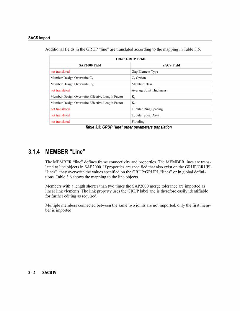
Additional fields in the GRUP “line” are translated according to the mapping in Table 3.5.
Other GRUP Fields
SAP2000 Field SACS Field
not translated Gap Element Type
Member Design Overwrite Cb Cb Option
Member Design Overwrite Cm Member Class
not translated Average Joint Thickness
Member Design Overwrite Effective Length Factor Ky
Member Design Overwrite Effective Length Factor Kz
not translated Tubular Ring Spacing
not translated Tubular Shear Area
not translated Flooding
Table 3.5: GRUP "line" other parameters translation
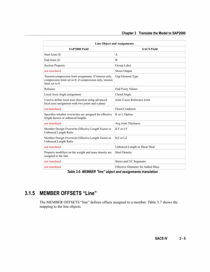
3.1.4 MEMBER “Line”
The MEMBER “line” defines frame connectivity and properties. The MEMBER lines are trans-lated to line objects in SAP2000. If properties are specified that also exist on the GRUP/GRUPL “lines”, they overwrite the values specified on the GRUP/GRUPL “lines” or in global defini-tions. Table 3.6 shows the mapping to the line objects.
Members with a length shorter than two times the SAP2000 merge tolerance are imported as linear link elements. The link property uses the GRUP label and is therefore easily identifiable for further editing as required.
Multiple members connected between the same two joints are not imported, only the first mem-ber is imported.
3 - 4 SACS IV
Chapter 3 Translate the Model to SAP2000
Line Object and Assignments
SAP2000 Field SACS Field
Start Joint (I) A
End Joint (J) B
Section Property Group Label
not translated Stress Output
Tension/compression limit assignment. If tension only, compression limit set to 0; if compression only, tension limit set to 0.
Gap Element Type
Releases End Fixity Values
Local Axes Angle assignment Chord Angle
Used to define local axes direction using advanced local axes assignment with two joints and a plane
Joint Z-axis Reference Joint
not translated Flood Condition
Specifies whether overwrites are assigned for effective length factors or unbraced lengths
K or L Option
not translated Avg Joint Thickness
Member Design Overwrite Effective Length Factor or Unbraced Length Ratio
KY or LY
Member Design Overwrite Effective Length Factor or Unbraced Length Ratio
KZ or LZ
not translated Unbraced Length or Shear Mod
Property modifiers on the weight and mass density are assigned to the line.
Steel Density
not translated Stress and UC Segments
not translated Effective Diameter for Added Mass
Table 3.6: MEMBER "line" object and assignments translation
3.1.5 MEMBER OFFSETS “Line”
The MEMBER OFFSETS “line” defines offsets assigned to a member. Table 3.7 shows the mapping to the line objects.
SACS IV 3 - 5
SACS Import
MEMBER OFFSETS Fields
SAP2000 Field SACS Field
Frame Joint Offsets to Cardinal Point Joint A – X, Y, Z
Frame Joint Offsets to Cardinal Point Joint B – X, Y, Z
Table 3.7: MEMBER OFFSETS "line" parameters translation
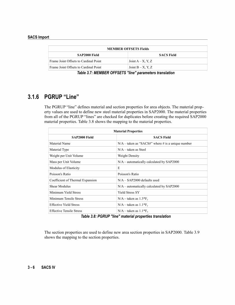
3.1.6 PGRUP “Line”
The PGRUP “line” defines material and section properties for area objects. The material prop-erty values are used to define new steel material properties in SAP2000. The material properties from all of the PGRUP “lines” are checked for duplicates before creating the required SAP2000 material properties. Table 3.8 shows the mapping to the material properties.
Material Properties
SAP2000 Field SACS Field
Material Name N/A – taken as “SACS#” where # is a unique number
Material Type N/A – taken as Steel
Weight per Unit Volume Weight Density
Mass per Unit Volume N/A – automatically calculated by SAP2000
Modulus of Elasticity E
Poisson's Ratio Poisson's Ratio
Coefficient of Thermal Expansion N/A – SAP2000 defaults used
Shear Modulus N/A – automatically calculated by SAP2000
Minimum Yield Stress Yield Stress SY
Minimum Tensile Stress N/A – taken as 1.3*Fy
Effective Yield Stress N/A – taken as 1.1*Fy
Effective Tensile Stress N/A – taken as 1.1*Fu
Table 3.8: PGRUP "line" material properties translation
The section properties are used to define new area section properties in SAP2000. Table 3.9 shows the mapping to the section properties.
3 - 6 SACS IV
Chapter 3 Translate the Model to SAP2000
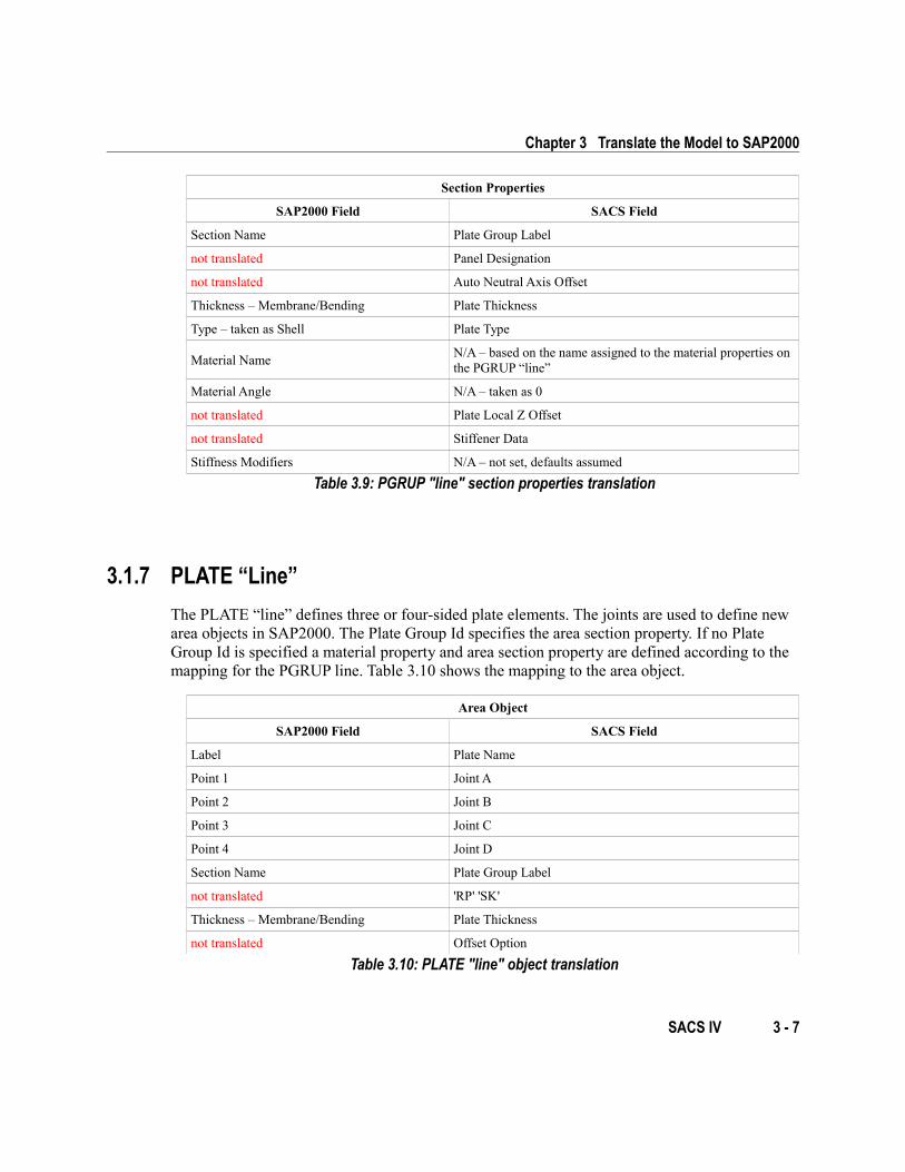
Section Properties
SAP2000 Field SACS Field
Section Name Plate Group Label
not translated Panel Designation
not translated Auto Neutral Axis Offset
Thickness – Membrane/Bending Plate Thickness
Type – taken as Shell Plate Type
Material NameN/A – based on the name assigned to the material properties on the PGRUP “line”
Material Angle N/A – taken as 0
not translated Plate Local Z Offset
not translated Stiffener Data
Stiffness Modifiers N/A – not set, defaults assumed
Table 3.9: PGRUP "line" section properties translation
3.1.7 PLATE “Line”
The PLATE “line” defines three or four-sided plate elements. The joints are used to define new area objects in SAP2000. The Plate Group Id specifies the area section property. If no Plate Group Id is specified a material property and area section property are defined according to the mapping for the PGRUP line. Table 3.10 shows the mapping to the area object.
Area Object
SAP2000 Field SACS Field
Label Plate Name
Point 1 Joint A
Point 2 Joint B
Point 3 Joint C
Point 4 Joint D
Section Name Plate Group Label
not translated 'RP' 'SK'
Thickness – Membrane/Bending Plate Thickness
not translated Offset Option
Table 3.10: PLATE "line" object translation
SACS IV 3 - 7
SACS Import
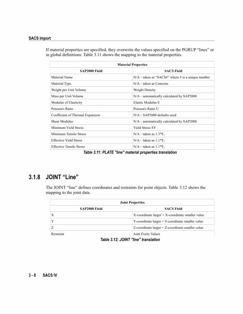
If material properties are specified, they overwrite the values specified on the PGRUP “lines” or in global definitions. Table 3.11 shows the mapping to the material properties.
Material Properties
SAP2000 Field SACS Field
Material Name N/A – taken as “SACS#” where # is a unique number
Material Type N/A – taken as Concrete
Weight per Unit Volume Weight Density
Mass per Unit Volume N/A – automatically calculated by SAP2000
Modulus of Elasticity Elastic Modulus E
Poisson's Ratio Poisson's Ratio U
Coefficient of Thermal Expansion N/A – SAP2000 defaults used
Shear Modulus N/A – automatically calculated by SAP2000
Minimum Yield Stress Yield Stress SY
Minimum Tensile Stress N/A – taken as 1.3*Fy
Effective Yield Stress N/A – taken as 1.1*Fy
Effective Tensile Stress N/A – taken as 1.1*Fu
Table 3.11: PLATE "line" material properties translation
3.1.8 JOINT “Line”
The JOINT “line” defines coordinates and restraints for point objects. Table 3.12 shows the mapping to the joint data.
Joint Properties
SAP2000 Field SACS Field
X X-coordinate larger + X-coordinate smaller value
Y Y-coordinate larger + Y-coordinate smaller value
Z Z-coordinate larger + Z-coordinate smaller value
Restraint Joint Fixity Values
Table 3.12: JOINT "line" translation
3 - 8 SACS IV
Chapter 3 Translate the Model to SAP2000
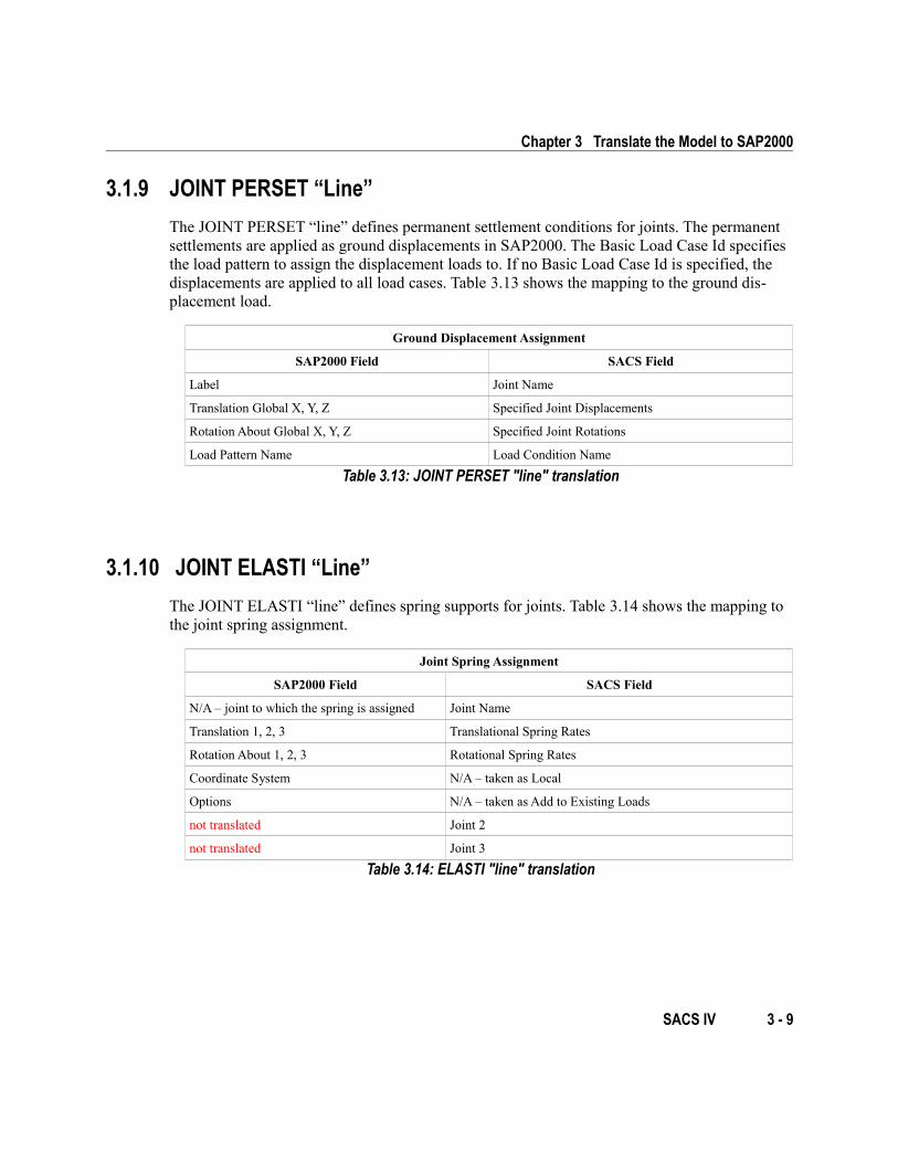
3.1.9 JOINT PERSET “Line”
The JOINT PERSET “line” defines permanent settlement conditions for joints. The permanent settlements are applied as ground displacements in SAP2000. The Basic Load Case Id specifies the load pattern to assign the displacement loads to. If no Basic Load Case Id is specified, the displacements are applied to all load cases. Table 3.13 shows the mapping to the ground dis-placement load.
Ground Displacement Assignment
SAP2000 Field SACS Field
Label Joint Name
Translation Global X, Y, Z Specified Joint Displacements
Rotation About Global X, Y, Z Specified Joint Rotations
Load Pattern Name Load Condition Name
Table 3.13: JOINT PERSET "line" translation
3.1.10 JOINT ELASTI “Line”
The JOINT ELASTI “line” defines spring supports for joints. Table 3.14 shows the mapping to the joint spring assignment.
Joint Spring Assignment
SAP2000 Field SACS Field
N/A – joint to which the spring is assigned Joint Name
Translation 1, 2, 3 Translational Spring Rates
Rotation About 1, 2, 3 Rotational Spring Rates
Coordinate System N/A – taken as Local
Options N/A – taken as Add to Existing Loads
not translated Joint 2
not translated Joint 3
Table 3.14: ELASTI "line" translation
SACS IV 3 - 9
SACS Import
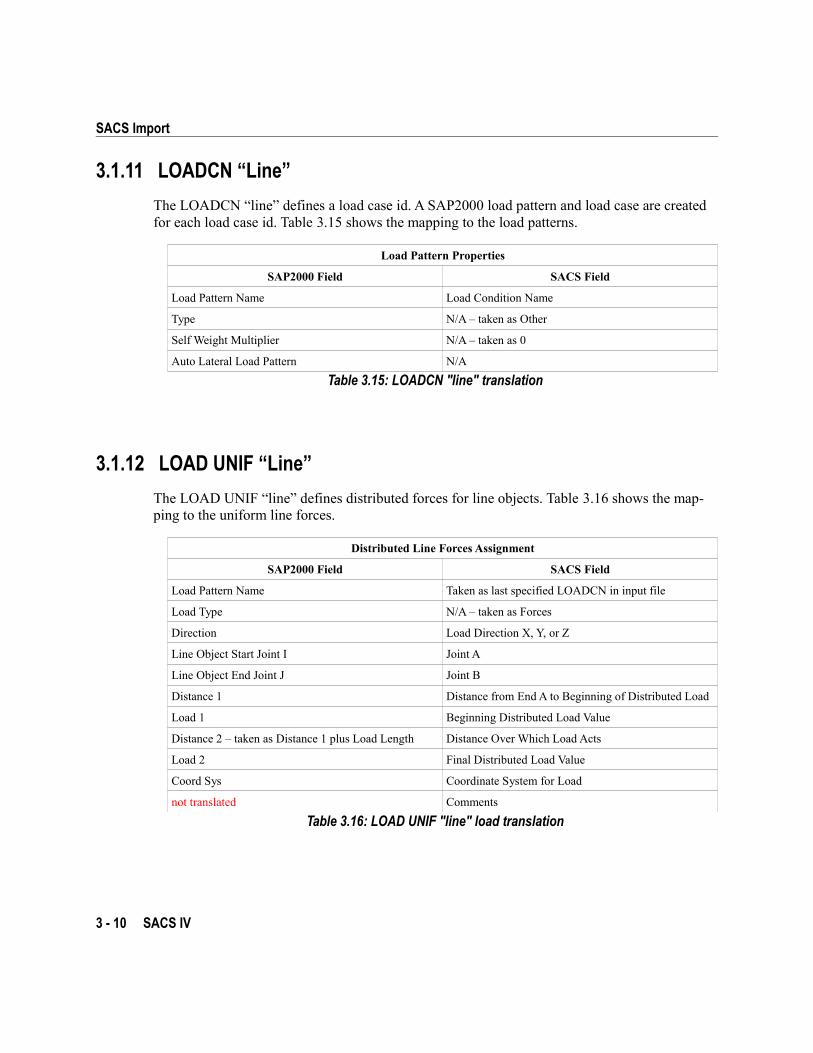
3.1.11 LOADCN “Line”
The LOADCN “line” defines a load case id. A SAP2000 load pattern and load case are created for each load case id. Table 3.15 shows the mapping to the load patterns.
Load Pattern Properties
SAP2000 Field SACS Field
Load Pattern Name Load Condition Name
Type N/A – taken as Other
Self Weight Multiplier N/A – taken as 0
Auto Lateral Load Pattern N/A
Table 3.15: LOADCN "line" translation
3.1.12 LOAD UNIF “Line”
The LOAD UNIF “line” defines distributed forces for line objects. Table 3.16 shows the map-ping to the uniform line forces.
Distributed Line Forces Assignment
SAP2000 Field SACS Field
Load Pattern Name Taken as last specified LOADCN in input file
Load Type N/A – taken as Forces
Direction Load Direction X, Y, or Z
Line Object Start Joint I Joint A
Line Object End Joint J Joint B
Distance 1 Distance from End A to Beginning of Distributed Load
Load 1 Beginning Distributed Load Value
Distance 2 – taken as Distance 1 plus Load Length Distance Over Which Load Acts
Load 2 Final Distributed Load Value
Coord Sys Coordinate System for Load
not translated Comments
Table 3.16: LOAD UNIF "line" load translation
3 - 10 SACS IV
Chapter 3 Translate the Model to SAP2000
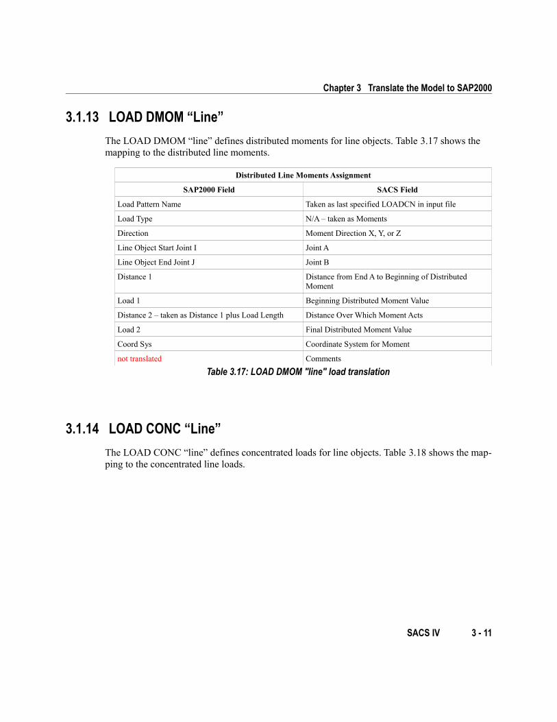
3.1.13 LOAD DMOM “Line”
The LOAD DMOM “line” defines distributed moments for line objects. Table 3.17 shows the mapping to the distributed line moments.
Distributed Line Moments Assignment
SAP2000 Field SACS Field
Load Pattern Name Taken as last specified LOADCN in input file
Load Type N/A – taken as Moments
Direction Moment Direction X, Y, or Z
Line Object Start Joint I Joint A
Line Object End Joint J Joint B
Distance 1 Distance from End A to Beginning of Distributed Moment
Load 1 Beginning Distributed Moment Value
Distance 2 – taken as Distance 1 plus Load Length Distance Over Which Moment Acts
Load 2 Final Distributed Moment Value
Coord Sys Coordinate System for Moment
not translated Comments
Table 3.17: LOAD DMOM "line" load translation
3.1.14 LOAD CONC “Line”
The LOAD CONC “line” defines concentrated loads for line objects. Table 3.18 shows the map-ping to the concentrated line loads.
SACS IV 3 - 11
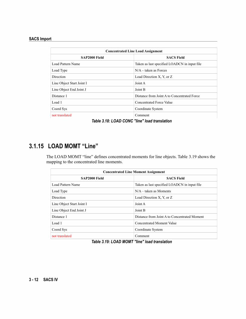
SACS Import
Concentrated Line Load Assignment
SAP2000 Field SACS Field
Load Pattern Name Taken as last specified LOADCN in input file
Load Type N/A – taken as Forces
Direction Load Direction X, Y, or Z
Line Object Start Joint I Joint A
Line Object End Joint J Joint B
Distance 1 Distance from Joint A to Concentrated Force
Load 1 Concentrated Force Value
Coord Sys Coordinate System
not translated Comment
Table 3.18: LOAD CONC "line" load translation
3.1.15 LOAD MOMT “Line”
The LOAD MOMT “line” defines concentrated moments for line objects. Table 3.19 shows the mapping to the concentrated line moments.
Concentrated Line Moment Assignment
SAP2000 Field SACS Field
Load Pattern Name Taken as last specified LOADCN in input file
Load Type N/A – taken as Moments
Direction Load Direction X, Y, or Z
Line Object Start Joint I Joint A
Line Object End Joint J Joint B
Distance 1 Distance from Joint A to Concentrated Moment
Load 1 Concentrated Moment Value
Coord Sys Coordinate System
not translated Comment
Table 3.19: LOAD MOMT "line" load translation
3 - 12 SACS IV
Chapter 3 Translate the Model to SAP2000
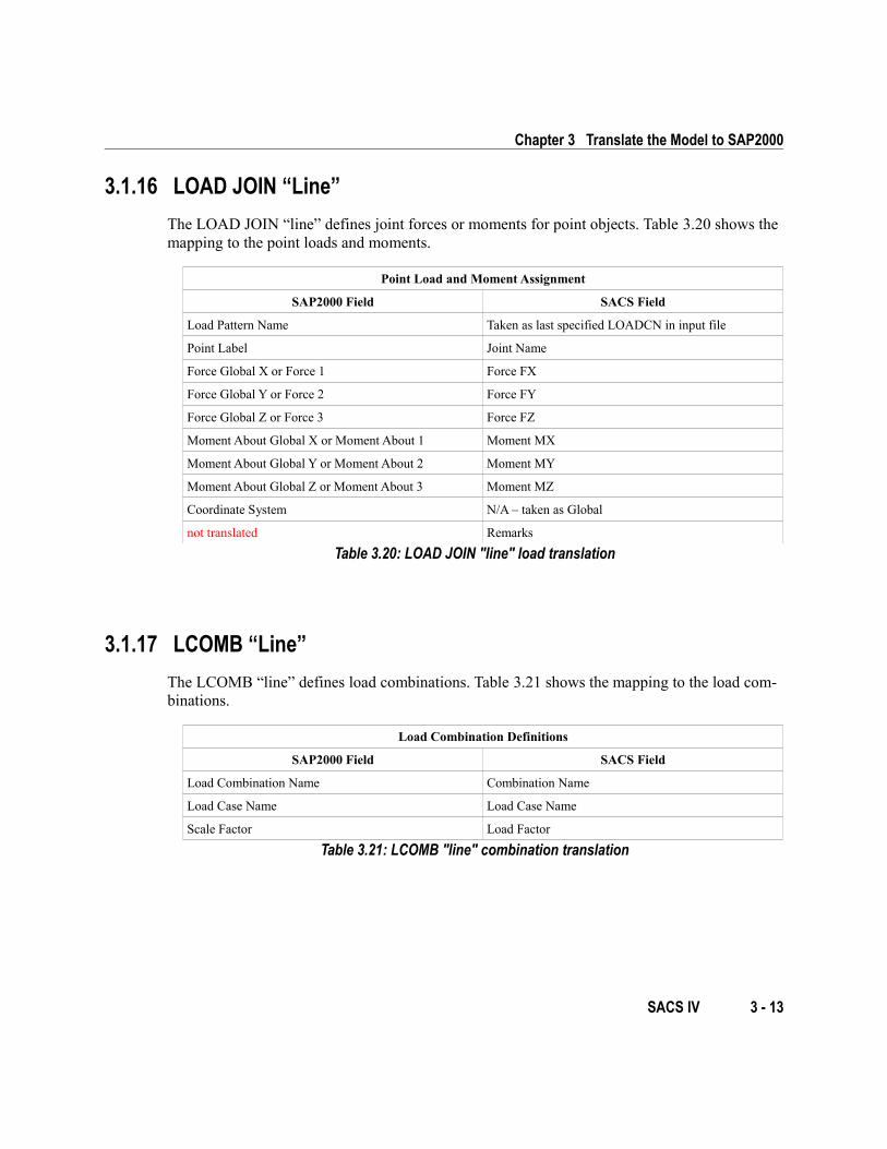
3.1.16 LOAD JOIN “Line”
The LOAD JOIN “line” defines joint forces or moments for point objects. Table 3.20 shows the mapping to the point loads and moments.
Point Load and Moment Assignment
SAP2000 Field SACS Field
Load Pattern Name Taken as last specified LOADCN in input file
Point Label Joint Name
Force Global X or Force 1 Force FX
Force Global Y or Force 2 Force FY
Force Global Z or Force 3 Force FZ
Moment About Global X or Moment About 1 Moment MX
Moment About Global Y or Moment About 2 Moment MY
Moment About Global Z or Moment About 3 Moment MZ
Coordinate System N/A – taken as Global
not translated Remarks
Table 3.20: LOAD JOIN "line" load translation
3.1.17 LCOMB “Line”
The LCOMB “line” defines load combinations. Table 3.21 shows the mapping to the load com-binations.
Load Combination Definitions
SAP2000 Field SACS Field
Load Combination Name Combination Name
Load Case Name Load Case Name
Scale Factor Load Factor
Table 3.21: LCOMB "line" combination translation
SACS IV 3 - 13