
RULES AND REGULATIONS FOR THE CONSTRUCTION AND ... · 1.1.1 The Rules for the construction and...
220
April 2017 CR Classification Society FOUNDED 1951 RULES AND REGULATIONS FOR THE CONSTRUCTION AND CLASSIFICATION OF SHIPS OF FIBREGLASS REINFORCED PLASTICS 2017 CR
Transcript of RULES AND REGULATIONS FOR THE CONSTRUCTION AND ... · 1.1.1 The Rules for the construction and...

April 2017
CR Classification SocietyFOUNDED 1951
RULES AND REGULATIONS FOR THE
CONSTRUCTION AND CLASSIFICATION OF
SHIPS OF FIBREGLASS REINFORCED
PLASTICS 2017
CR


April 2017
CR Classification SocietyFOUNDED 1951
CR
RULES AND REGULATIONS FOR THE
CONSTRUCTION AND CLASSIFICATION OF
SHIPS OF FIBREGLASS REINFORCED
PLASTICS 2017


RULES AND REGULATIONS FOR THE
CONSTRUCTION AND CLASSIFICATION OF
SHIPS OF FIBREGLASS REINFORCED
PLASTICS 2017
PART I – GENERAL REQUIREMENTS
April 2017

RULES AND REGULATIONS FOR THE
CONSTRUCTION AND CLASSIFICATION OF SHIPS
OF FIBREGLASS REINFORCED PLASTICS
PART I GENERAL REQUIREMENTS 2017
PART II HULL CONSTRUCTION 2017
PART III EQUIPMENT AND FITTINGS 2017
PART IV MACHINERY INSTALLATIONS 2017
PART V ELECTRICAL INSTALLATION 2017

List of major changes in Part I from 1998 edition
Nil.

RULES AND REGULATIONS FOR
THE CONSTRUCTION AND CLASSIFICATION OF SHIPS OF
FIBREGLASS REINFORCED PLASTICS
2017
PART I
GENERAL REQUIREMENTS
CONTENTS
Chapter 1 General ......................................................................................................................................... 1
1.1 Application.................................................................................................................................................. 1 1.2 Classification and Survey of FRP Ships ..................................................................................................... 1 1.3 Definitions .................................................................................................................................................. 3 1.4 Regulations ................................................................................................................................................. 3
Chapter 2 Materials ...................................................................................................................................... 4
2.1 General ........................................................................................................................................................ 4 2.2 Definitions .................................................................................................................................................. 4 2.3 Fibreglass Reinforcement ........................................................................................................................... 5 2.4 Resins .......................................................................................................................................................... 6 2.5 Core Materials............................................................................................................................................. 6 2.6 FRP Strength Tests ...................................................................................................................................... 7 2.7 Testing Procedures for Fibreglass Reinforcements ..................................................................................... 8 2.8 Test Procedures for Resins for Laminating ............................................................................................... 15 2.9 Test Procedures for Core Material for Sandwich Constructions ............................................................... 23 2.10 Test Procedures of FRP Strength Tests ..................................................................................................... 28
Chapter 3 Works .......................................................................................................................................... 33
3.1 General ...................................................................................................................................................... 33 3.2 Storage of Raw Materials .......................................................................................................................... 33 3.3 Moulding Shops ........................................................................................................................................ 33 3.4 Quality Control ......................................................................................................................................... 34
Chapter 4 Moulding .................................................................................................................................... 35
4.1 General ...................................................................................................................................................... 35 4.2 Environmental Conditions of Moulding Shops ......................................................................................... 35 4.3 Gel Coats .................................................................................................................................................. 35 4.4 Manual Lamination ................................................................................................................................... 35 4.5 Spray Moulding ........................................................................................................................................ 36 4.6 Sandwich Construction ............................................................................................................................. 36 4.7 Curing and Mould Releasing .................................................................................................................... 36

Chapter 5 Connection and Fastening ........................................................................................................ 37
5.1 General ...................................................................................................................................................... 37 5.2 Matting-in Connection .............................................................................................................................. 37 5.3 Mechanical Fastening ............................................................................................................................... 38 5.4 Attachment of Metal Fittings .................................................................................................................... 38

- 1 -
I.1
Chapter 1
General
1.1 Application
1.1.1 The Rules for the construction and classification of ships for fibreglass reinforced plastics (hereinafter
referred to as the Rules) apply to the design, material, construction and equipment for ships of fibreglass reinforced
plastics (hereinafter referred to as "FRP ships") intended to be assigned and registered classification with CR
Classification Society (hereinafter referred to as the Society).
1.1.2 The requirements in the Rules are framed for FRP ships, with a designed speed not exceeding 7.19920.1667
(kt) ( = displacement in m3 corresponding to the load line defined in 1.3.6) other than oil tankers, of normal form and
proportion, less than 35 meters in length, intended for unrestricted service. Special considerations will be given to
large ships, ships for restricted service, ships of unusual form or proportion, novel design and arrangement, or ships
intended for the carriage of special cargoes, the requirements for construction, equipment and scantlings may be
properly modified.
1.1.3 The requirements in the Rules are applied to ships having structures of single skin laminates with stiffeners or
sandwich constructions, moulded by hand lay-up method or spray lay-up method, using fibreglass reinforcements and
unsaturated polyester resins.
1.1.4 Reinforcement materials other than fibreglass and resins other than polyester may be accepted based upon
testing and approval in each individual case. Alternative constructing method, structural arrangement, equipment and
scantlings are to be considered to the Society's satisfaction that they are equivalent to the requirements of the Rules.
1.2 Classification and Survey of FRP Ships
1.2.1 The classification and register of FRP ships are also to be in accordance with the applicable provisions in Part
I of the "Rules for the Construction and Classification of Steel Ships" (hereinafter referred to as "the Steel Ship Rules
").
1.2.2 FRP ships with their class approved by the Society are to be recorded in the Register, and assigned a
descriptive notation (FRP Hull) affixed to the classification symbols.
1.2.3 Except specified otherwise in this Chapter, The classification surveys of FRP ships are generally to comply
with the requirements in Part I of the Steel Ships Rules. Plan review and surveys during or after construction are to be
conducted by the Society to verify that the construction, material, equipment, machinery and electrical installation are
in compliance with the Rules.
1.2.4 When FRP ships intended to be built under classification survey during construction, Plans or documents
showing the following details are to be submitted and approved before the work is commenced:
(a) General arrangement
(b) List and data for raw materials
(c) Midship section
(d) Construction profile and deck plan
(e) Scantling calculation
(f) Laminating procedure and details of joint connections
(g) Watertight and oiltight bulkhead
(h) Superstructure and deckhouse

- 2 -
I.1
(i) Fore and aft construction
(j) Shaft strut
(k) Rudder and steering gear
(l) Main engine and auxiliary machinery foundations
(m) Hatch and closing appliances
(n) Opening construction on weather deck
(o) Arrangement and details of hull port, door and window
(p) Arrangement and details of fire safety appliances and systems
(q) Machinery arrangement
(r) Propeller and shafting, or propulsion system
(s) Piping systems
(t) Electrical systems
(u) Automatic and remote control systems of machinery, if CAS, CAU or CAB applied
(v) Main engine, deck machinery and essential auxiliaries
(w) Other plans and documents deemed necessary by the Society
1.2.5 In addition to those required by 1.2.4, the following plans or documents are to be submitted for reference,
when FRP ships are intended to be built under classification survey during construction:
(a) Specifications
(b) Lines and body plan
(c) Capacity plan
(d) Certificates of the FRP material tests
(e) Submission of plans and documents other than those specified above may be required where deemed
necessary by the Society.
1.2.6 In the classification survey during construction, inspections are to be carried out covering all stages of work
from its commencement until completion. The presence of the Surveyor is required at the following stages of work:
(a) Designated by the Society during commencement of moulding, curing and mould releasing
(b) Test of FRP materials specified in Chapter 2 of Part I
(c) Connection of mouldings (e.g., deck to shell)
(d) Testing of hull castings and forgings
(e) Hydrostatic test and watertight test
(f) Test of main and auxiliary machinery
(g) Sea trail

- 3 -
I.1
The stages for which the Surveyor's inspection required may be modified according to the actual status of facilities,
technical abilities and quality control system of the works.
1.2.7 Periodical surveys are generally to be in accordance with the provisions in 1.6 of Part I of the Steel Ships
Rules. In addition, the fuel oil tanks made of FRP are to be examined internally at the bottom survey.
1.2.8 In the classification of FRP ships not built under the Society's survey, the actual scantlings of main structure
of the ship are to be confirmed by suitable means in addition to the inspection of hull, equipment, machinery, electrical
installations, intact safety and fire protection as required for the special survey to the ship's age. Plans and documents
required for the classification survey during construction are generally to be submitted for review and records.
1.3 Definitions
1.3.1 Length of ship (L) is the distance in meters on the designed load line defined in 1.3.6, from the fore side of
stem to the axis of rudder stock. In case of a ship with a cruiser stern, L is as defined above or 96% of the total length
on the load line, whichever is the greater.
1.3.2 Breath of ship (B) is the horizontal distance in meters between outsides of shell laminates measured on the
upper surface of upper deck laminates at side at the broadest part of the hull.
1.3.3 Depth of ship (D) is the vertical distance in meters measured at the middle of L, from lower surface of bottom
laminates or the intersection of the extension line of lower surface of bottom laminates with the center line of ship
(hereinafter referred to as "the base point of D") to upper surface of upper deck laminates at side.
1.3.4 Midship part of ship is the parts for 0.4L amidships unless specified otherwise.
1.3.5 The end parts of ship are the parts for 0.1L from either end of the ship.
1.3.6 Load line is the waterline corresponding to the summer load draught in case of a ship which is required to be
assigned with load lines, or the waterline corresponding to the designed maximum draught in case of a ship which is
not required to be assigned with load lines.
1.3.7 Load draught (d) is the vertical distance in meters from the base point of D to the load line.
1.3.8 Freeboard deck is the uppermost continuous deck which has permanent means of weathertight closing of all
openings in the weather part thereof, and below which all openings in the ship side are fitted with permanent means of
watertightly closing. In a ship having a discontinuous freeboard deck, the lowest line of the exposed deck and the
continuation of that line parallel to the upper part of the deck is taken as freeboard deck.
1.3.9 Strength deck is the uppermost deck which forms the top of effective hull girder at any part of its length and
normally to which the shell laminates extend. In case of superstructures other than a sunken superstructure, which are
not considered effective to longitudinal strength, the strength deck is the deck just below the superstructure deck.
1.3.10 Superstructure is an enclosed structure on the main weather deck having side plating as an extension of the
side shell, or not fitted inboard of the hull side more than 4% of the breadth.
1.4 Regulations
1.4.1 While the Rules cover the requirements for the classification of FRP ships, owner, designer and builder are
strongly recommended to deal with the regulations of governmental and other authorities in addition to the
requirements of the Rules.
1.4.2 Where authorized by the Administration whose flag the ship (hereinafter refer to as the administration) is
entitled to fly, and upon request of owners or builders of the ship, the Society is to review plans, survey and certify the
new or existing ship for compliance with the provisions of relevant International Conventions or Codes.

- 4 -
I.2
Chapter 2
Materials
2.1 General
2.1.1 The requirements in this chapter apply to raw materials for FRP structure and FRP laminates. Materials other
than plastics, such as metallic materials, are to be in accordance with requirements in Part XI of the Steel Ships Rules.
2.1.2 Details of the fibreglass reinforcements, resins and sandwich core materials proposed to be used for FRP
ships are to be submitted for approval before construction is commenced. The materials are to be accepted on the basis
of a detailed description confirming the information given by the manufacturer with inspection and test results to the
satisfaction of the surveyor.
2.1.3 At the request of manufacturers for type approval of materials, the Society is to examine the manufacturing
process, inspection standards and quality control system of the works. Inspections and approval tests of materials from
current production are to be carried out in the presence of the surveyor.
2.1.4 The following materials are subject to type approval:
(a) Fibreglass reinforcements,
(b) Polyester products,
(c) Core materials for sandwich construction.
The type approval for each material grade is valid for a period of 5 years and will be published in the Society's list of
type approved products. The approval may be withdrawn or revoked if the manufacturing process and/or material
conditions at the time of approval no longer are fulfilled. The renewal of type approval certificate is to be normally
assessed by checking of production control records, random inspection and sample testing.
2.2 Definitions
2.2.1 Resin
Resin is a reactive synthetic normally unsaturated polyester for laminating and gelcoat which is a liquid in initial stage
but transformed into solid upon activation with adding substances.
(a) Polyester resin is a thermosetting resin that is formed by combining saturated and unsaturated organic acids
such as orthophthalic and isophthalic acids.
(b) Vinylester resin is a thermosetting resin that consists of a polymer chain and an acrylate or methacrylate
termination.
(c) Epoxy resin is a resin that contains one or more of the epoxide groups.
(d) Accelerator is a material that, when mixed with resin, speed the cure time.
(e) Additive is a added substance usually to improve resin properties, such as plasticizers, initiators, light
stabilizers and flame retardants.
(f) Catalyst is a material that is used to activate resin, causing it to harden.
(g) Cure time is the time required for resin to change from a liquid to a solid after a catalyst has been added.
(h) Gel time is the time required to change a flowable, liquid resin into a non-flowing gel.
(i) Exothermic heat is the heat given off as the result of the action of a catalyzed resin.

- 5 -
I.2
(j) Inhibitor is a material that retards activation or initiation of resin, thus extending shelf life or influencing
exothermic heat or gel time.
(k) Pot life is the length of time that a catalyzed resin remains workable.
(l) Shelf life is the length of time that an uncatalyzed resin maintains its working properties while stored in a
tightly sealed opaque container.
2.2.2 Reinforcement
Reinforcement is a material bonded into the plastic to improve its strength, stiffness and impact resistance.
Reinforcements are usually fibers of glass, or other material such as aramid or carbon fiber.
(a) Chopped strand mat is a fibreglass of blanket type in uniform thickness with strands of non-alkali
fibreglass cut in proper length randomly oriented and held together with binder.
(b) Woven roving is a coarse fabric fibreglass woven in plain with parallel strands or rovings made of
non-alkali fibreglass.
(c) Strand is a bundle of continuous filaments combined in a single, compact unit.
(d) Roving is a band or ribbon of parallel strands grouped together.
(e) Yarn is a twisted strand or strands suitable for weaving into a fabric.
(f) Binder is a polyester applied in small quantities to hold fibers together in mat form.
(g) Cloth is a fabric woven from yarn.
2.2.3 Laminate
Laminate is a material composed of successive bonded layers, or piles, of resin and fiber or other reinforced
substances.
(a) Gel coat is the first resin applied to mould when fabricating a laminate to provide a smooth protective
surface for laminate.
(b) Lay-up is the process of applying to a mould the layers of resin and reinforcing materials that make up a
laminate. These materials are then compressed or densified with a roller or squeegee to eliminate entrapped
air and to spread resin evenly.
(c) Peel ply is a partially impregnated, lightly bonded layer of fibreglass used to protect a laminate in
anticipation of secondary bonding providing a cleaned fresh bonding surface.
(d) Primary bonding is the practice of bonding between two laminated surfaces when the resin on both surfaces
has not yet cured.
(e) Secondary bonding is the practice of bonding fresh materials to a cured or partially cured laminate.
(f) Post cure is the act placing a laminate in higher temperature to assist in the cure cycle of the resin.
2.3 Fibreglass Reinforcement
2.3.1 Properties regarding following items are to be tested and inspected:
(a) Appearance,
(b) Weight per unit area and its maximum deviation,
(c) Ratio in weight of residual binders or knitting agents,
(d) Tensile strength of fibreglass, in case of woven rovings,
- 6 -
I.2
(e) Tensile strength and modulus of tensile elasticity obtained from laminated test specimens,
(f) Bending strength and modulus of bending elasticity obtained from laminated test specimens.
2.3.2 Test results are to meet manufacturer's specifications and to verify the properties used in design of laminates.
Moisture content in reinforcement is to be observed.
2.3.3 Where coupling agents are used, they are to be of the saline compound or complex chromium compound
which are compatible with the laminating resins.
2.3.4 For roving which will be applied by spraying, a demonstration is to be made showing that the roving is
suitable for this kind of application.
2.3.5 The glass is to be of E-quality. Fibers made of other glass qualities, S or R glass, carbon or aramid fibers may
be used subject to special agreement and provided that their mechanical properties and water resistance are equal or
better.
2.4 Resins
The properties of a resin are to be of final form actually used in laminating with all additives and fillers included. The
following properties of resins in liquid condition, cured condition and curing characteristics are to be provided.
2.4.1 Liquid properties ( at 25 °C)
(a) Viscosity and thixotropic index
(b) Acid value
(c) Gel time, indicate initiator (catalyst) and activator (promoter) content %, the minimum cure time and Peak
exothermic temperature.
2.4.2 Cured properties of resin casting
(a) Load deflection temperature of resin casting
(b) Water absorption of resin casting
(c) Barcol hardness of resin casting
(d) Tensile strength and modulus of laminated test specimens
(e) Bending strength and modulus of laminated test specimens
2.5 Core Materials
2.5.1 Core materials used for sandwich construction such as honeycomb, rigid plastic foam, balsa wood are to be of
sufficient tensile, compressive and shear strength which are to be verified by test for use in the design. If the core
materials are manufactured into formable sheets of small blocks, the open weave backing material and adhesive are to
be compatible and soluble with the laminating resin.
2.5.2 Following properties of core materials are to be examined:
(a) Specific gravity
(b) Water absorption
(c) Tensile strength and modulus
(d) Compressive strength and modulus
(e) Shear strength, modulus and elongation

- 7 -
I.2
2.5.3 Rigid plastic foams are to be compatible with the resin system, have stable aging property, resistant to water
and oils. The construction methods and procedures using foam cores are to be in accordance with manufacturer's
recommendation.
2.5.4 Balsa woods are to be end grained, treated against fungal and insect attack and dried to have an average
moisture content of 12%.
2.5.5 Plywood and timbers used in conjunction with plastic construction are to be seasoned, free from knots, shakes
and other defects, of water resistance and suitably treated so as to have good adhesion to reinforced plastics.
2.6 FRP Strength Tests
2.6.1 The FRP strength tests are to be carried out upon completation of laminate works of FRP Ships and in case
where scantling are modified according to the requirements specified in 1.2.2 of Part II before plans being submitted
for approval and construction.
2.6.2 The test specimens for FRP material tests are to be cut from the laminates and sandwich laminates taken from
the actual laminates or the laminates and sandwich laminates equivalent thereto. The test specimens are to be tested
and inspected as follows:
(a) FRP laminates (including FRP laminates of outer skin of sandwich laminates),
(i) Thickness of moulding
(ii) Barcol hardness
(iii) Glass content
(iv) Bending strength
(v) Modulus of bending elasticity
(vi) Tensile strength
(vii) Modulus of tensile elasticity
(b) Sandwich laminates
(i) Thickness of moulding of sandwich laminates
(ii) Tensile strength of sandwich laminates, only in case where the cores are born a load in the scantling
calculation. In this case, the test specimens involving joints of cores are to be included.
(iii) Shearing strength of sandwich laminates, in case where the cores are reckoned in the bending
strength, the test specimens involving joints of cores are to be included.
2.6.3 The FRP strength tests are to be carried out, at least on the structural members specified as follows:
(a) Bottom shell laminates
(b) Side shell laminates
(c) Upper deck laminates
(d) Bulkhead (only of sandwich construction)
2.6.4 The results of FRP strength tests specified as follows are to be submitted to the Society.
(a) Names of fibreglass reinforcements, resins for laminating and cores for sandwich construction
(b) Names and amount of application of fillers
(c) Names and amount of application of sclerotics and accelerators
(d) Procedures and conditions of moulding
(e) Direction of selection of test specimens

- 8 -
I.2
(f) Dates of moulding and tests of test specimens
(g) Place of tests and environmental condition of the site of tests
(h) Types of testing machines
(i) Form and dimensions of test specimens
(j) Test results
2.6.5 The five test specimens are to be subjected to the FRP strength tests, unless specially specified, and the
arithmetical mean of the smaller three values obtained from the five specimens is to be taken as the test result.
2.7 Testing Procedures for Fibreglass Reinforcements
2.7.1 Shape and selection of test specimens
(a) The shape and selection of test specimens used for tests of fibreglass reinforcements are to be in
accordance with Table I 2-1.
(b) The manufacturing methods of laminated sheet used for tests (excluding rovings for spray-up laminating)
are to be in accordance with the following:
(i) The laminated plate used for tests is to have a sufficient size to arrange all the required laminated
test specimens by itself after trimming away a 30 mm breadth of its edges.
(ii) The laminate constitution and glass content are to be as the following table.
Laminate constitution Glass content
Chopped mat 3-ply 30 3 (%)
Woven Roving 4-ply 50 3 (%)
(iii) The ambient temperature while laminating is to be within the temperature range stated in the
specifications.
(iv) The laminating operation is to be completed within 50% of the gel time of resins for the ambient
temperature.
(v) After completion of laminating operation, the laminated plate is to be left for 24 hours at a
temperature of 20 5 °C, and to be subjected to curing for 16 hours in air bath at a temperature of
40 °C. The laminated plate may be cut up in proper sizes for the after cure.
(c) The manufacturing method of laminated plate used for the test of rovings for spray-up are to be in
accordance with the following:
(i) The size of test specimens is to be as specified in the preceding 2.7.1(b)(i)
(ii) The thickness of the test specimen is to be not less than 3mm.
(iii) The glass content is to be 30 3%.
(iv) The after cure is to be in accordance with the preceding 2.7.1(b)(v)
2.7.2 Test Procedures
The procedure of the tests given in 2.3.1 is to be in accordance with the following:
(a) Design weight per unit area or unit length and the maximum deviation.
(i) The test samples are to be in accordance with Table I 2-1.
(ii) The weight of the test sample is to be measured to the accuracy of 0.1g.
(iii) The deviation is to be of the value obtained from the following formulae.
(1) Chopped mats and woven roving
- For test sample of 1 m2
| M1 - W |
W ×100 (%)

- 9 -
I.2
- For test sample of 300×300 m2
| M2 / 0.09 - W |
W ×100 (%)
where:
M1 = Weight of test sample of 1 m2, in g
M2 = Weight of test sample of 300×300 mm2, in g
W = Weight of test sample per 1 m2 intended to be stated in the specification, in g
(2) Rovings
100W
W/M1000
l (%)
where:
l = Length of test sample, in m
W = Weight per 1,000 m to be stated in specification, in g
M = Weight of test sample, in g
(b) Ratio in weight of binder (including sheafing agents)
(i) The test specimen are to be in accordance with Table I 2-1
(ii) Each test specimen is to be heated in a heating furnace (625 25°C) for about 10 minutes to burn
out the binder or sheafing agent, then to be taken out from the furnace and left it to cool down to the
room temperature.
(iii) The test sample in (ii) above is to be weighed to the accuracy of 0.1 g.
(iv) The ratio in weight of binders (including sheafing agent) is to be of the value obtained from the
following formula.
W0 - W1
W0 ×100 (%)
where:
W0 = Weight before heating, in g
W1 = Weight after cooling, in g
(c) Tensile strength of fibreglass in woven roving
(i) The test specimen are to be in accordance with Table I 2-1
(ii) The standard tensile speed is to be 200 mm/min.
(iii) When the test specimen failed or slipped at the grip of the testing machine, the measured value of
this test sample is to be judged unacceptable. In such a case, an additional test specimen is to be
taken for test.
(iv) The breaking load is to be taken as the tensile strength of fibreglass.
(d) Bending strength and modulus of bending elasticity obtained from laminates
(i) The test specimen is to be in accordance with Table I 2-1.
(ii) The test is to be carried out after keeping the test specimen in the standard condition for 20 hours or
more.
(iii) The testing arrangement of three point bending is to be in accordance with Fig. I 2-5.
(iv) The standard loading rate during test is to t/2 mm/min. (t = thickness of the test specimen in mm).
(v) The bending strength is to be of the value obtained from the following formula.
2bt
P
2
3 l
N/mm2
where:
P = Breaking load, in N

- 10 -
I.2
l = Gauge length, in mm
b = Breadth of test specimen, in mm
t = Thickness of test specimen, in mm
(vi) The modulus of bending elasticity is to be of the value obtained from the following formula.
dy
dP
bt4 3
3
l
N/mm2
where:
(dP/dy) = Gradient of the straight portion of load-deflection curve, in N/mm
y = Deflection at mid point of gauge length, in mm
l, b and t = As specified in (v) above
(e) Tensile strength and modulus of tensile elasticity obtained from laminates.
(i) The test specimens are to be in accordance with Table I 2-1.
(ii) The tests are to be carried out after keeping the test specimen in the standard condition for 20 hours
or more.
(iii) The standard tensile speed is to be 5 mm/min.
(iv) When the test specimen failed outside the gauge length, the measured values of the test specimen
are to be judged unacceptable. In such a case, an additional test specimen is to be taken for test.
(v) The tensile strength is to be of the value obtained from the following formula.
P
A N/mm
2
where:
P = Breaking load, in N
A = Sectional area of test specimen at its mid point, in mm2
(vi) The modulus of tensile elasticity is to be of the value obtained from the following formula.
l
l
d
dP
A N/mm2
where:
l = Original gauge length, in mm
A = Sectional area at mid point of test specimen, in mm2
(dP/dl) = Gradient of the straight portion of load-deflection curve, in N/mm
dl = Elongation of the distance between gauge marks

- 11 -
I.2
Table I 2-1
Fibreglass Reinforcements
Paragraph 2.7.2 Shape and size of test specimen Quantity Sampling procedure, etc.
(a) Deviation type1
type2
(in mm)
A=1 m2
300
× 300
type 1 ................ 5 pcs
type 2 .............. 10 pcs
Discard 30 mm from one
longitudinal end and 30 mm from
both transverse ends, and take a test
sample of 1 m2 continuously in the
longitudinal direction (See Fig. I 2-1)
After measuring weight of test
sample (type 1), take a square (300×
300) test specimen therefrom. (See
Fig. I 2-2)
Rovings for spray-up are to have
a length equivalent to
approximately 15 g.
5 pcs
(b) Ratio in weight
of binders
Same as type 2 in (a) 5 pcs
(c) Tensile strength
of fibreglass 30
250 (in mm)
warp direction ... 5 pcs
weft direction ... 5 pcs
Test specimens are to be taken in
warp and weft direction,
respectively. (See Fig. I 2-3)
Finish it in the shape as shown in
Fig. I 2-4
(d)
&
(e)
Bending strength
obtained from
laminates
250.5
t = original thickness. (in mm)
tNot less than
80
5 pcs In woven roving, 5 pieces of test
specimens are to be taken in warp
and weft direction, respectively.
Finish the cutout section smoothly.
(f) Tensile strength
obtained from
laminates
R
W
G
F t
t = original thickness
F = 60 0.5 (mm)
G = 50 0.5 (mm)
W = 25 (mm) or more
R = 60 (mm) or more
standard condition
........................ 5 pcs
In woven roving, 5 pieces of test
specimens are to be taken from
warp and weft direction respectively.
Finish the cutout section smoothly.

- 12 -
I.2
bbb b
b
A
A
A
A
a
aa
A = approx. 1 m2
a = 30 mm b = 300 mm
Fig. I 2-1
Selection of Test Specimens from Fibreglass
Reinforcements
Fig. I 2-2
Selection of Test Specimens from
Fibreglass Reinforcements

- 13 -
I.2
a
b
AbB
a
A: the test specimen in the direction of warp
B: the test specimen in the direction of weft
a = approx. 30 mm
b = approx. 250 mm
Fig. I 2-3
Selection of Tensile Test Specimen from Woven Roving Reinforcements
Gri
p
approx. 250 mm
approx. 150 mm
25 m
m
app
rox
. 3
0 m
m
Gri
p
Fig. I 2-4
Tensile Test Sample of Woven Roving
t
l = 1 5 t ~ 1 7 t
R 3 . 2 m m
o r m o r e R 3 . 2 m m o r
m o r e
R 5 m m o r m o r e
P
Fig. I 2-5
Testing Arrangement of Three Point Bending
This part of fibre is to be
removed, and the breadth of
finished specimen is to be
25 mm
- 14 -
I.2
Table I 2-2
Acceptance Criteria for Fibreglass Reinforcements
Test item Acceptance criteria
Deviation Chopped mat 1m2 .............................. Not greater than 10% for each specimen
300mm×300mm .......... Not greater than 20% for each specimen
Woven Roving 1m2 .............................. Not greater than 3% for each specimen
300mm×300mm .......... Not greater than 5% for each specimen
Rovings 15g ............................... Not greater than 10% for each specimen
Ratio in weight of
residual binders
Chopped mat Mean value ................ Not greater than 10%
Test results of at least 4 test specimens are not to be greater than 10%
Woven Roving Mean value ................ Not greater than 1%
Test results of at least 4 test specimens are not to be greater than 1%
Rovings Mean value ................ Not greater than 3%
Test results of at least 4 test specimens are not to be greater than 3%
Tensile strength of fibreglass of glass
woven roving
Mean value .................. Not less than 0.35W (kg)
W: the stated weight (g)
Test results of at least 4 test specimens in 5 test specimens of respective warp
and weft directions are not to be less than 0.35W (kg)
Chopped mat
Roving
Bending strength Mean value ................ Not less than 160 N/mm2
Test results of at least 4 test specimens are not to be less than 157 N/mm2
Modulus of
bending elasticity
Mean value ................ Not less than 7000 N/mm2
Test results of at least 4 test specimens are not to be less than 7000 N/mm2
Woven Roving Bending strength Mean value ................ Not less than 280 N/mm2
Test results of at least 4 test specimens are not to be less than 280 N/mm2
Modulus of
bending elasticity
Mean value ................ Not less than 12900 N/mm2
Test results of at least 4 test specimens are not to be less than 12900 N/mm2
Chopped mat
Roving
Tensile strength Mean value ................ Not less than 85 N/mm2
Test results of at least 4 test specimens are not to be less than 85 N/mm2
Modulus of tensile
elasticity
Mean value ................ Not less than 7500 N/mm2
Test results of at least 4 test specimens are not to be less than 7500 N/mm2
Woven Roving Tensile strength Mean value ................ Not less than 190 N/mm2
Test results of at least 4 test specimens are not to be less than 190 N/mm2
Modulus of tensile
elasticity
Mean value ................ Not less than 1600 N/mm2
Test results of at least 4 test specimens are not to be less than 1600 N/mm2

- 15 -
I.2
2.8 Test Procedures for Resins for Laminating
2.8.1 Shapes and Selection of Test Specimens
(a) The shape and selection of test specimens used for the tests of resins for laminating are to be in accordance
with Table I 2-3.
(b) The manufacturing methods of resin casting test specimens are to be in accordance with the following:
(i) The sclerotics and accelerators are to be as specified by the manufacturer of the resins.
(ii) The size of cast sheet is to be such that all test specimens required in Table I 2-3 for the resin
casting test specimen can be cut out of the sheet.
(iii) The cure time, temperature and after cure are to be as specified by the manufacturer of resins.
(c) The manufacturing procedures of laminates used for tests are to be in accordance with the following :
(i) The laminating arrangements is to be of chopped mat with weight per unit area of 450 g/m2 in 3-ply
and the glass content is to be 30 3% in weight.
(ii) For other procedures, apply to the requirements in 2.7.1(b) correspondingly.
2.8.2 Test Procedures
The procedures for the tests given in 2.4 are to be in accordance with the following:
(a) Viscosity and thixotropy
(i) The test resins are to be as given in Table I 2-3.
(ii) Brookfield viscometer is to be used.
(iii) The rotor and guard (or sleeve guard) chosen according to the predicted viscosity of the liquid
sample are to be mounted on the viscometer.
(iv) The test liquid resins (25 0.5 °C) after being stirred well are to be filled into the beaker to a depth
so that the reference mark on the rotor may be equal to the liquid level.
(v) After leaving still for approximately 5 minutes and then turning the rotor at a rotational speed of 60
rpm for 3 minutes, the reading of the scale is to be taken. The viscosity is to be obtained by
multiplying the reading by a coefficient determined according to the type of rotor used and
rotational speed.
(vi) After keeping still for another 5 minutes and then turning the rotor at a rotational speed of 6 rpm for
3 minutes, the reading is to be taken for obtaining the viscosity.
(vii) The thixotropy index is to be obtained by dividing the viscosity determined at the rotor run of 6 rpm
by the viscosity at 60 rpm.
(viii) The operations shown in (v) and (vi) above are to be repeated for two times or more and the
respective mean values are to be regarded as the "viscosity" and "thixotropy index".
(b) Gel time, minimum cure time and peak exothermic temperature.
(i) The test resins are to be given in Table I 2-3.
(ii) The testing apparatus for hardening characteristics at room temperature is to be fixed in a
thermostatic water bath (25 0.5 °C). (See Fig. I 2-6)
(iii) The test resins are to be dipped in the thermostatic water bath and then the specified amount of
sclerotics is to be added thereto when the temperature of the test resins reached 25 0.5 °C, and the
mixture is to be stirred evenly.
(iv) The test resins added with sclerotics are to be filled into a test tube of 18 mm in diameter to a depth
of 100 mm.
(v) The 18mm dia. test tube is to be fixed in a test tube of 30 mm in diameter so that the top surface of
the test resins assumes approximately 10 mm below the liquid surface of the thermostatic water
bath.
(vi) The welded junction of thermocouple is to be placed at half the depth of the test resins and to be
fixed at the centre of the test tube. However, a thermocouple ensleeved in a protection tube or a
thermister may be used in place of the above thermocouple.
- 16 -
I.2
(vii) The time in minutes required for the test resins to reach a temperature of 30 °C from the time when
the sclerotic are mixed is to be taken as the gel time, and the time in minutes required to reach the
highest temperature after adding the sclerotics is to be taken as the minimum cure time, and the
temperature indicated as the maximum temperature of the test resin is to be taken as the peak
exothermic temperature (°C).
30
18
9
50
50
100
Air mantle
Test tube
Test tube for
thermal insulation
Welded junction of
thermocouple
Test resin
Bath liquid
Stoppers
Adhesive tape
Approx. 10
165
Fig. I 2-6
Testing Apparatus for Hardening Characteristics at Room Temperature

- 17 -
I.2
(viii) Measurements are to be taken for two or more times, and the respective mean values are to be
regarded as the "gel time", "minimum cure time" and "peak exothermic temperature".
(ix) The types and amounts of the sclerotics and accelerators are to be recorded.
(c) Acid value
(i) Take 1 g of the test resins, add it to about 10 ml of mixed solvent[mixture of 7 parts by mass of
toluene (reagent) and 3 parts by mass of methyl alcohol (reagent)], and stir the mixture well.
(ii) Add the mixed indicator and titrate the solution with 0.1 mole/l ethyl alcoholic potassium hydroxide
solution.
(iii) When the colour of the solution turns from green into pale violet, take it as a point of termination.
(iv) The acid value is to be of the value obtained from the following formula.
5.61υ
S
where:
υ = Consumption of 0.1 mole/l ethyl alcoholic potassium hydroxide, in ml
= Factor of 0.1 mole/l ethyl alcoholic potassium hydroxide
S = Mass of test resins, in g
The mixed indicator is the reagent obtained by adding 20 ml of distilled water to 0.1 g of finely
ground bromthymol blue and 0.1 g of phenol red, and adding further 0.1 mole/l ethyl alcoholic
potassium hydroxide solution thereto to the discolouring range while stirring it well, and by diluting it
further with distilled water to a volume of 200 ml.
(d) Water absorption rate of cast test specimens
(i) The test specimens are to be in accordance with Table I 2-3.
(ii) Put a filter paper on an asbestos board (thickness: approximately 10 mm), place the test specimen
thereon, and heat the test specimen in a thermostatic air oven (50 2 °C) for 24 1 hours.
(iii) Cool the test specimen subjected to heating process in (2) above in a desiccator and measure the
weight.
(iv) Immerse the test specimen in a container with a lid filled with sufficient volume of distilled water,
leave the container in a thermostatic water bath (25 1 °C) for 24 hours, and then take the test
specimen out, wipe the surface water and measure the weight. During immersion in distilled water,
the test specimens are to be hold not to be brought in contact with each other.
(v) The water absorption rate is to be of the value obtained form the following formula.
(%)100W
WW
0
01
where:
W0 = Weight of test specimen after heating, in g
W1 = Weight of test specimen after immersion in water, in g
(e) Barcol hardness of cast test specimens
(i) Use the Barcol hardness tester.
(ii) Hold the hardness tester in such a manner that the point contacts at right angles with the test ing
surface of the test specimen which is placed on a hard base.
(iii) Apply 4.5 kg to 6.8 kg of an impact pressure and read out the maximum indication on the hardness
tester.
(iv) Ensure that the measuring point is 3 mm or more apart from the periphery of test specimen and
other measuring points, and that those measuring points clear the areas from which other test
specimens are taken.
(v) Take measurements at least 10 points.
(f) Tensile elongation and tensile strength of the cast test specimens.
- 18 -
I.2
(i) The test specimens are to be in accordance with Table I 2-3.
(ii) The standard tensile speed is to be 5 mm/min.
(iii) When the test specimen failed outside the place between gauge points, the measured value of such a
test specimen is to be judged unacceptable, and a new test specimen is to be taken for additional
test.
(iv) The tensile elongation is to be obtained from the following formula.
Elongation of the gauge length at failure
Initial gauge length×100 (%)
(v) The tensile strength is to be obtained from the following formula.
P
A N/mm
2
where:
P = Breaking load, in N
A = Sectional area of test specimen at mid point, in mm2
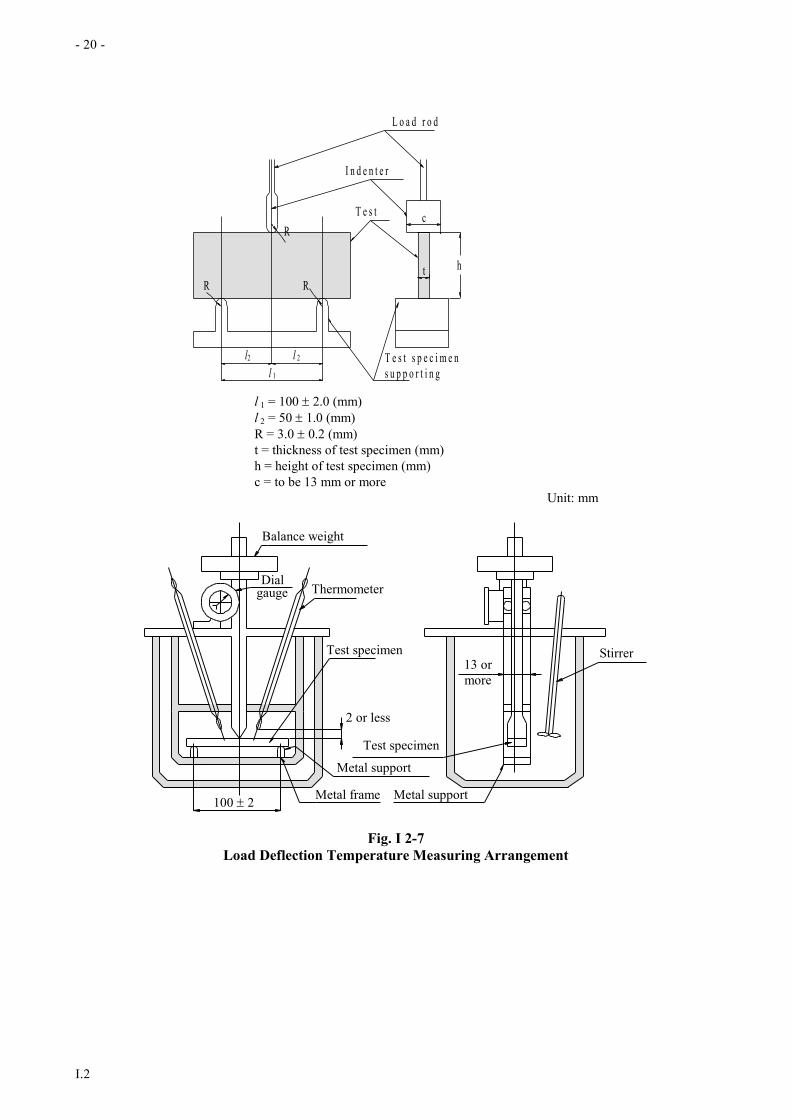
(g) Load deflection temperature of cast test specimens
(i) The test specimens are to be in accordance with Table I 2-3.
(ii) The testing apparatus is to be as shown in Fig. I 2-7.
(iii) The weight of balance weight is to be of the value obtained from the following formula.
Qth
123.02
l kg
where:
t = Thickness of test specimen, in mm
h = Height of test specimen, in mm
l = Distance between supports, in mm
Q = Weight, in kg, obtained by adding the load reading on a dial gauge to the weight of
loading rod including the weight pan.
(iv) Fix the testing apparatus with the test specimen in an oil bath, apply load and leave it from the
initial temperature of 25 1 °C for 5 minutes.
(v) Raise the temperature of the oil bath at a rate of 2.0 0.2 °C /min.
(vi) The temperature when the deflection reaches 0.26 mm is to be taken as the load deflection
temperature.
(h) Barcol hardness of the laminate test specimens
The requirements in (e) above are to apply correspondingly.
(i) Bending strength and modulus of bending elasticity obtained by laminate test specimens
(i) The test specimens are to be in accordance with Table I 2-3.
(ii) The testing procedures are to be in accordance with 2.7.2(d).
(j) Tensile strength and modulus of tensile elasticity obtained by laminate test specimens.
(i) The test specimens are to be in accordance with Table I 2-3.
(ii) The testing procedures are to be in accordance with 2.7.2(f).
(k) High temperature characteristics obtained by laminate test specimens.
(i) Barcol hardness
Leave the test specimen at 60 1 °C for 24 hours and carry out the test specified in (e) above within
one minute.
(ii) Bending strength and modulus of bending elasticity

- 19 -
I.2
Leave the test specimen at a temperature of 60 1 °C for 24 hours and then carry out the test specified
in (i) above at a temperature of 60 2 °C.
- 20 -
I.2
h
T e s t s p e c i m e n
s u p p o r t i n g
b a s e
l 1
l2 l 2
R R
R
t
c T e s t
s p e c i m e n
I n d e n t e r
L o a d r o d
l 1 = 100 2.0 (mm)
l 2 = 50 1.0 (mm)
R = 3.0 0.2 (mm)
t = thickness of test specimen (mm)
h = height of test specimen (mm)
c = to be 13 mm or more
Unit: mm
Metal frame Metal support100 2
Metal support
Stirrer13 or
more
Test specimen
2 or less
Test specimen
ThermometergaugeDial
Balance weight
Fig. I 2-7
Load Deflection Temperature Measuring Arrangement

- 21 -
I.2
Table I 2-3
Resins for Laminating (Unit: mm)
Paragraph 2.8.2 Shape and size of test specimen Quantity Selection of test specimen, etc.
(a) Viscosity and
thixotropy
index
Resins As required When resins are sampled, the
contents of vessel are to be stirred
well to make them homogeneous,
and take test resins into a suitable
dry and clean vessel of two times
the necessary volume for test and
a light-proof plug is to be
provided
(b) Gel time,
minimum cure
time and peak
exothermic
temperature
Resins 501g
(Note)
(c) Acid value Resins 1 g
(d) Water
absorption rate 501
501 30.2
5 cast test
specimens
(e)
(h)
Barcol hardness Cast test specimens
Laminate test specimens
(g) Load deflection
temperature 12.70.2
Not less than 110 6.40.2
3 cast test
specimens
(f)
(j)
Tensile strength R
W
G
F t
Cast test specimens
t = 3 0.2 (mm)
F = 60 0.5 (mm)
G = 50 0.5 (mm)
W = 12.5 (mm) or more
R = 60 (mm) or more
Laminate test specimens
t = original thickness
F = 60 0.5 (mm)
G = 50 0.5 (mm)
W = 25 (mm) or more
R = 60 (mm) or more
5 cast test
specimens
5 laminate test
specimens
(i) Bending
strength of
laminated test
specimens
250.5
Not less than 180
5
(k) High
temperature
characteristics
of laminated
test specimens
The same as in (h) and (i)
Note: In the case of no-accelerated resins, the specified amount of accelerators is to be added and stirred according to
the weight of the resins.
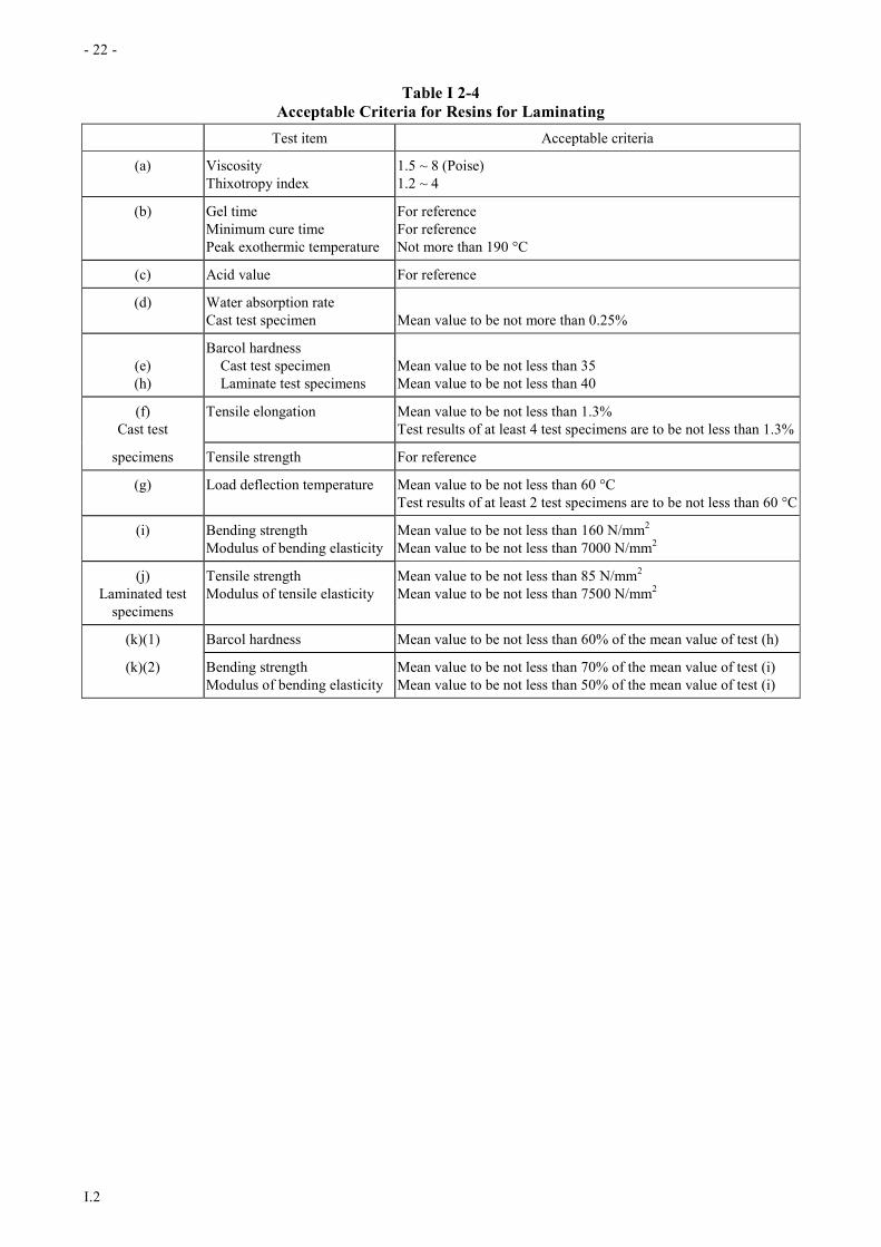
2.8.3 Criteria
The acceptable criteria of the test results are to be not less than the value given in Table I 2-4.
- 22 -
I.2
Table I 2-4
Acceptable Criteria for Resins for Laminating
Test item Acceptable criteria
(a) Viscosity
Thixotropy index
1.5 ~ 8 (Poise)
1.2 ~ 4
(b) Gel time
Minimum cure time
Peak exothermic temperature
For reference
For reference
Not more than 190 °C
(c) Acid value For reference
(d) Water absorption rate
Cast test specimen
Mean value to be not more than 0.25%
(e)
(h)
Barcol hardness
Cast test specimen
Laminate test specimens
Mean value to be not less than 35
Mean value to be not less than 40
(f)
Cast test
Tensile elongation Mean value to be not less than 1.3%
Test results of at least 4 test specimens are to be not less than 1.3%
specimens Tensile strength For reference
(g) Load deflection temperature Mean value to be not less than 60 °C
Test results of at least 2 test specimens are to be not less than 60 °C
(i) Bending strength
Modulus of bending elasticity
Mean value to be not less than 160 N/mm2
Mean value to be not less than 7000 N/mm2
(j)
Laminated test
specimens
Tensile strength
Modulus of tensile elasticity
Mean value to be not less than 85 N/mm2
Mean value to be not less than 7500 N/mm2
(k)(1) Barcol hardness Mean value to be not less than 60% of the mean value of test (h)
(k)(2) Bending strength
Modulus of bending elasticity
Mean value to be not less than 70% of the mean value of test (i)
Mean value to be not less than 50% of the mean value of test (i)
- 23 -
I.2
2.9 Test Procedures for Core Material for Sandwich Constructions
2.9.1 Shapes and Selection of Test Specimens
(a) The shape and selection of test specimens used for the test of core materials for sandwich construction are
to be in accordance with Table I 2-5.
(b) The manufacturing methods of sandwich constructions for the test are to be in accordance with the
following:
(i) The core material is to be the largest thickness to be used as primary structural members of hull
construction.
(ii) On both sides of the core, the M-R-M-R-M laminates are to be applied, where M denotes chop mats
(weight per unit area 600 g/m2) and R, woven roving (weight per unit area 810 g/m2).
(iii) The glass content is to be approximately 30% at the portion of chops mats, and approximately 50%
at the portion of woven roving.
(iv) The direction of warp of the woven roving is to be aligned with the longitudinal direction of the test
specimen.
(v) In the case of the fibre reinforced plastics foam, test specimens of which longitudinal direction is
aligned respectively with the direction of the maximum strength and the direction of the minimum
strength of the core material are to be manufactured.
2.9.2 Test Procedures
(a) The test procedures for the hard plastics foam specified in 2.5.2 are to be in accordance with the following:
(i) Specific gravity
(1) The test specimens are to be in accordance with Table I 2-5.
(2) Leave the test specimen in a thermostatic air oven (25 0.5 °C) for about 30 minutes and
measure the dimension and weight.
(3) The size of the test specimen is to be measured to an order of 0.1 mm for the thickness, length
and breadth.
(4) The weight of the test specimen is to be measured to the order of 0.1 g.
(5) The specific gravity is to be for the value obtained from the following formula.
W/V
where:
W = Weight of test specimen, in g
V = Weight of pure water corresponding to the volume of test specimen, in g
(ii) Water absorption rate
(1) The test specimens are to be in accordance with Table I 2-5.
(2) The surface skin of the test specimen, if such is the case, is to be removed, and the dimensions
are to be measured to the order of 0.1 mm.
(3) The test specimen is to be submerged in fresh water (23 3 °C, 60 mm in depth below the
water surface) for 10 seconds.
(4) The test specimens is to be placed on a wire gauze of 3 mm mesh titled at 30 degree to the
vertical for 30 seconds, and then the reference weight (Wo) is to be measured to the order of
0.01g.
(5) The test specimens of which reference weight has been measured is to be soaked in fresh water
(23 3 °C) for 24 hours with a pressure of 10 N/mm2.
(6) The weight of the test specimen (W1) is to be measured by the same procedure as specified in
(4) above.
(7) The water absorption rate is to be obtained from the following formula.
W1 - W0
A ×100 g/100cm2

- 24 -
I.2
where:
W1 = Weight after the final water absorption, in g
W0 = Reference weight, in g
A = Surface area of test specimen, in cm2
(iii) Compressive strength and modulus of compressive elasticity.
(1) The test specimens are to be in accordance with Table I 2-5.
(2) The size of the test specimen is to be measured to the order of 0.1 mm.
(3) Compression to be applied in the direction thickness of the product.
(4) The standard compression speed is to be 5 mm/min.
(5) The compressive strength is to be obtained from the following formula.
Pc
A N/mm2
where:
Pc = Load at which 0.2% strain is occurred from the elastic limit, in N
A = Pressure bearing area of test specimen, in mm2
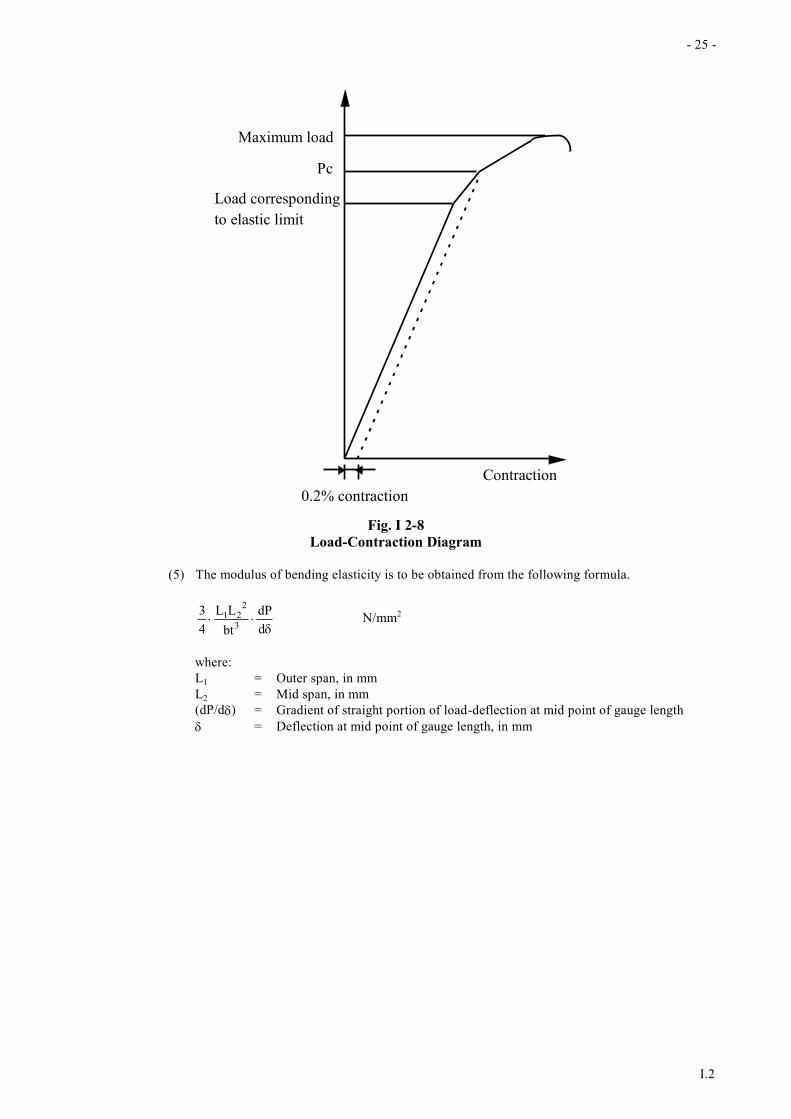
(6) The modulus of compressive elasticity is to be obtained
dt
dP
A
t N/mm2
where:
(dP/dt) = Gradient of the straight portion of load-contraction curve, in N/mm (See Fig. I
2-8)
t = Thickness of test specimen
A = Pressure bearing area of test specimen, in mm2
(iv) Softening rate
The modulus of compressive elasticity at a temperature of 60 °C is to be measured by suitable means.
The method specified in 2.8.2(g) may be applied correspondingly.
(v) Tensile strength and modulus of tensile elasticity
(1) The test specimens are to be in accordance with Table I 2-5.
(2) The test procedure is to be in accordance with 2.7.2(f).
(vi) Bending strength and modulus of bending elasticity.
(1) The test specimens are to be in accordance with Table I 2-5.
(2) The testing arrangement of four point bending is to be in accordance with Fig. I 2-9.
(3) The standard loading speed is to be t/2 mm/min.
t = thickness of test specimen, in mm
(4) The bending strength is to be obtained from the following formula.
3PL1
bt2 N/mm2
where:
L1 = Outer span, in mm
b = Breadth of test specimen, in mm
t = Thickness of test specimen, in mm
P = Breaking load, in N
- 25 -
I.2
Maximum load
Pc
Load corresponding
to elastic limit
Contraction
0.2% contraction
Fig. I 2-8
Load-Contraction Diagram
(5) The modulus of bending elasticity is to be obtained from the following formula.
d
dP
bt
LL
4
33
221 N/mm2
where:
L1 = Outer span, in mm
L2 = Mid span, in mm
(dP/d) = Gradient of straight portion of load-deflection at mid point of gauge length
= Deflection at mid point of gauge length, in mm

- 26 -
I.2
L2 = 100 mm L1L1
RR
RR
R = 3.2 mm or more
Fig. I 2-9
Testing Arrangement of Four Point Bending
(vii) Shearing strength of sandwich constructions
(1) The test specimens are to be in accordance with Table I 2-5.
(2) The testing arrangement of four point bending is to be in accordance with Fig. 2-9
(3) The standard loading speed is to be t/2 mm/min.
t = thickness of test specimen, in mm
(4) The shearing strength is to be obtained from the following formula.
btt2
P
cf
b
N/mm2
where:
Pb = Breaking load of core material, in N
tf = Mean thickness of inner layer and outer layer of FRP laminates, in mm
tc = Thickness of core material, in mm
b = Breadth of test specimen, in mm
(5) The outer span (L1) is to be referred to the value obtained from the following formula.
However, in case where either the outer or inner FRP laminates fails, retest is to be carried out
with the smaller outer span.
L1 < ccf
f
btt
Z
mm
where:
Z = Section modulus of test specimen, in mm3
tf = Mean thickness of FRP laminates, in mm
tc = Thickness of core material, in mm
B = Breadth of test specimen, in mm
f = Tensile strength of FRP laminates, in N/mm2
c = Imaginary shearing strength of core material, in N/mm2
(b) The test procedures for balsa are to be in accordance with the following:
(i) Specific gravity
The test procedure is to be in accordance with 2.9.2(a)(i). However, the size and weight are to be
measured at room temperature.
(ii) Moisture content
(1) After having dried the test specimen in (i) above in the thermostatic air oven to a fixed weight,
the weight is to be measured to the order of 0.1g.
- 27 -
I.2
(2) The moisture content is to be of the value obtained from the following formula.
W1-W2
W2 ×100 (%)
where:
W1 = Weight at the standard condition, in g
W2 = Weight after drying, in g
(iii) Compressive strength in fibrous direction and modulus of compressive elasticity.
The test procedure is to be in accordance with 2.9.2(a)(iii). However, Pc shown in (5) is the maximum
load (N). In this case, the specific gravity of the test specimen is to have been measured in accordance
with (i) above.
(iv) Shearing strength of sandwich constructions.
The test procedure is to be in accordance with 2.9.2(a)(vii).

- 28 -
I.2
Table I 2-5
Core Materials for Sandwich Construction (Unit: mm)
Paragraph 2.9.2(a)/(b) Shape and size of test specimen Quantity Selection of test specimen, etc.
(1) Specific gravity Hard plastic foam
100
t: original thickness 100 t
5
Balsa
Product balsa of original thickness
Compression test specimen (3) is to
be used
10
5
Product balsa boards (artificially dried
balsa boards bonded in the same direction
(block) to be cut at right angle to fibrous
direction) are to be taken from different
lots as far as practicable.
(2) Water absorption The same as in hard plastic foam 5
(2) Moisture content
100
t: original thickness 100 t
10 One each test specimen is to be taken
from each product balsa of which the
specific gravity was measured.
(3) Compression test Hard plastic foam
a = 50 (mm)
Balsa a = 20 ~ 50 (mm)
t = 50 (mm)
FibreDirection
a
at
5 Materials for test are to be selected as
differently on specific gravity as possible
among those forming a block of balsa
products, and test specimens are to be
taken from those respective materials.
(5) Tensile test R
W
G
F t
t = original thickness or 20 (mm)
F = 600.5 (mm)
G = 500.5 (mm)
W = 25 (mm) or more
R = 60 (mm) or more
5
(6) Bend test 50
350 or more t t = original thickness or 20 (mm)
5
(7) Shearing test 500.5
600 or more t t : to be in accordance with 2.9.1(b)(i)
5
2.10 Test Procedures of FRP Strength Tests
2.10.1 Manufacture of test laminates for FRP laminates and sandwich constructions
- 29 -
I.2
TB
BT
TB
60 mm or more60 mm or more
60 mm or more
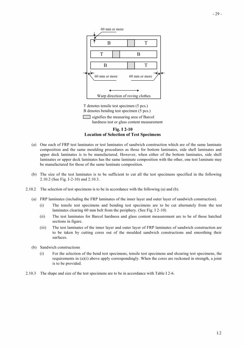
Warp direction of roving clothes
T denotes tensile test specimen (5 pcs.)
B denotes bending test specimen (5 pcs.)
signifies the measuring area of Barcol
hardness test or glass content measurement
Fig. I 2-10
Location of Selection of Test Specimens
(a) One each of FRP test laminates or test laminates of sandwich construction which are of the same laminate
composition and the same moulding procedures as those for bottom laminates, side shell laminates and
upper deck laminates is to be manufactured. However, when either of the bottom laminates, side shell
laminates or upper deck laminates has the same laminate composition with the other, one test laminate may
be manufactured for those of the same laminate composition.
(b) The size of the test laminates is to be sufficient to cut all the test specimens specified in the following
2.10.2 (See Fig. I-2-10) and 2.10.3.
2.10.2 The selection of test specimens is to be in accordance with the following (a) and (b).
(a) FRP laminates (including the FRP laminates of the inner layer and outer layer of sandwich construction).
(i) The tensile test specimens and bending test specimens are to be cut alternately from the test
laminates clearing 60 mm belt from the periphery. (See Fig. I 2-10)
(ii) The test laminates for Barcol hardness and glass content measurement are to be of those hatched
sections in figure.
(iii) The test laminates of the inner layer and outer layer of FRP laminates of sandwich construction are
to be taken by cutting cores out of the moulded sandwich constructions and smoothing their
surfaces.
(b) Sandwich constructions
(i) For the selection of the bend test specimens, tensile test specimens and shearing test specimens, the
requirements in (a)(i) above apply correspondingly. When the cores are reckoned in strength, a joint
is to be provided.
2.10.3 The shape and size of the test specimens are to be in accordance with Table I 2-6.

- 30 -
I.2
Table I 2-6
Shape and Size of Test Specimens
Item Test specimen Quantity
FRP laminates Sandwich construction
Thickness of moulding Bend test specimen and tensile test
specimen are to be used
Bend test specimen, shearing test specimen
and tensile test specimen are to be used
Glass content 2g or more for each one
The periphery is to be finished smoothly
3
Bend test specimen
and shearing test
specimen
Bend test specimen
b
20t or more t
Shearing test specimen
b
l t
Co
res
L1 L2 L1
C
Cores
Joint
t = original thickness
L1 = 100 ~ 200 (mm)
L2 = 100 (mm)
l = 2L1+L2+60 (mm)
C = approx. 10 (mm)
(When the cores are reckoned in strength, a
joint is to be provided at the position
shown on the drawing.)
5
t (mm) b (mm) t (mm) b (mm)
Not more than 20
Over 20 but not more than 35
Over 35 but not more than 50
30 0.5
50 0.5
80 0.5
Not more than 20
Over 20 but not more than 35
Over 35 but not more than 50
30 0.5
50 0.5
80 0.5
Tensile test specimen R
W
G
F t
t = original thickness
F = 600.5 (mm)
G = 500.5 (mm)
W = 25 (mm) or more
R = 60 (mm) or more
R
W
G
F t
Joint
t = original thickness
F = 600.5 (mm)
G = 500.5 (mm)
W = 25 (mm) or more
R = 60 (mm) or more
When the cores are reckoned in strength,
a joint is to be provided at the centre of
the parallel part.
The gripped portion is to be reinforced.
5

-31-
I.2
2.10.4 The test procedures are to be in accordance with the following:
(a) FRP laminates
(i) Thickness of moulding
The thickness of five individual bend test specimens and tensile test specimens is to be measured.
(ii) Barcol hardness
For the test procedures, the requirements in 2.8.2(e) apply correspondingly.
(iii) Glass content (ratio in weight)
(1) After drying a crucible in an electric muffle furnace (650 20 °C) till its weight reaches
constant, cool the pot in a desiccator and measure weight of the crucible (W1).
(2) Place the test sample (2 g or more specified in 2.10.2 above into the crucible and measure
weight (W2).
(3) Apply heat with a Bunsen burner or an electric muffle furnace so that the test sample continues
burning properly.
(4) After completion of burning, apply heat in the electric muffle furnace at 625 °C until the
carbon content completely disappears.
(5) Cool the test object in a desiccator for 30 minutes and measure its weight (W3).
(6) The glass content is to be obtained from the following formula.
W3-W1
W2-W1 ×100 (%)
(iv) Bending strength and modulus of bending elasticity.
(1) The test specimens are to be in accordance with Table I 2-6
(2) For the test procedures, the requirements in 2.7.2(d) apply correspondingly.
(v) Tensile strength and modulus of tensile elasticity.
(1) The test specimens are to be in accordance with Table I 2-6.
(2) For the test procedures, the requirements in 2.7.2(f) apply correspondingly.
(b) Sandwich constructions
(i) Thickness of moulding
The thickness of the shearing test specimens and tensile test specimens is to be measured.
(ii) Tensile strength
(1) The test specimens are to be in accordance with Table I 2-6.
(2) The standard tensile speed is to be 5mm/min.
(3) When the test specimen fails at position outside the gauge length, the measured values of the
test specimen are not to be accepted and an additional test specimen is to be tested additionally.
(4) The tensile strength is to be of the value obtained from the following formula.
f
ccf
E
EAA
P
N/mm2
where:
P = Breaking load, in N
Ac = Sectional area of core, in mm2
Af = Sectional area of FRP laminates, in mm2
Ec = Modulus of tensile elasticity of core obtained by the test in 2.5.2 of Part I, in
N/mm2
Ef = Modulus of tensile elasticity of FRP laminates obtained by (a) above, in N/mm2
-32-
I.2
(iii) Shearing strength
(1) The test specimens are to be in accordance with Table I 2-6.
(2) The test procedures are to be in accordance with 2.9.2 (a)(vii). The side of FRP with a thicker
layer is to be taken as the compression side.
2.10.5 The acceptable criteria of the test results are to be not less than the value given in Table I 2-7.
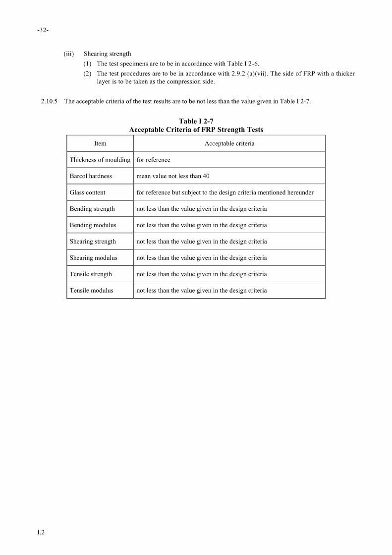
Table I 2-7
Acceptable Criteria of FRP Strength Tests
Item Acceptable criteria
Thickness of moulding for reference
Barcol hardness mean value not less than 40
Glass content for reference but subject to the design criteria mentioned hereunder
Bending strength not less than the value given in the design criteria
Bending modulus not less than the value given in the design criteria
Shearing strength not less than the value given in the design criteria
Shearing modulus not less than the value given in the design criteria
Tensile strength not less than the value given in the design criteria
Tensile modulus not less than the value given in the design criteria

-33-
I.3
Chapter 3
Works
3.1 General
3.1.1 Works intended to manufacture FRP ships are to be approved in accordance with the requirements in this
Chapter.
3.1.2 In application for works approval, the manufacturer is required to submit detailed data and documents
introducing the workshop, facilities, productions, and quality control system, etc. The facilities of the works, storage
of materials and quality control system are to be inspected to the satisfaction of the Society.
3.1.3 In the works approval procedure, a qualification test of sample panels assembled by the works under
environmental conditions and using material and process as actual production are to be carried out if deemed
necessary. The test conditions and result are to be in accordance with those requirements for laminates in Chapter 2.
3.2 Storage of Raw Materials
3.2.1 Storage facilities for raw materials are to be of sound construction and of reasonable standard that material
supplier's instruction for storage and handling can be followed.
3.2.2 Fibreglass materials are to be stored in clean and dry spaces.
3.2.3 Resins, accelerators, sclerotics and gelcoats are to be stored in cool spaces and shielded from direct sunlight.
Storage temperature and storage periods are to be within the limits specified by the material supplier. Tanks for
polyesters are to be arranged as far as possible so that the contents can be stirred every day.
3.2.4 Core materials are to be stored dry and protected against mechanical damage.
3.3 Moulding Shops
3.3.1 Moulding shops are to be constructed free from penetration of draught, dust, moisture, etc. and so arranged as
to be reasonable in consideration of handling materials, laminating process and curing condition.
3.3.2 The air temperature in the moulding shops while laminating is to be kept suitable for the resins used with
consideration of the blending proportion. The temperature is not to be lower than 18°C unless expressly specified
otherwise. It is recommended that the temperature is not to vary by more than 3°C during moulding. If necessary,
temperature conditioners are to be provided in the shops.
3.3.3 The relative humidity of the air is to be kept at a preferable not lower than 60% and is not to exceed 80% that
condensation is avoided. In areas where spray moulding is taking place, the air humidity is not to be less than 40%. If
necessary, suitable appliances are to be provided for reducing the humidity.
3.3.4 Air temperature and relative humidity are to be recorded regularly. The number and location of the
instruments in the shops are to present the environmental conditions as neutral as possible.
-34-
I.3
3.3.5 Ventilation facilities are to be so arranged that the curing process of laminates is adapted without any bad
influences.
3.3.6 Shops lighting is to be adequate but not to accelerate the cure of resin. Suitable means of shielding the
skylights and windows are to be provided so that lamination and curing process are not exposed to direct sunlight.
3.3.7 Sufficient scaffoldings are to be arranged so that lamination work can be carried out without operator
standing on surfaces where lamination is taking place.
3.4 Quality Control
3.4.1 The works is to have an efficient system for quality control to ensure that the product quality meets the
specific requirements.
3.4.2 Quality control system shall be formalized through containing following objects:
(a) Organization and responsibility of quality control.
(b) Production guidance and workmanship.
(c) Procedures for inspection and test.
(d) Documentation and records of all quality related activities.
3.4.3 The quality control system shall at least comprise inspection and control routines for the followings:
(a) Raw material procurement and quality.
(b) Storage conditions for raw materials.
(c) Environmental conditions during manufacturing.
(d) Production procedures.
(e) Workmanship.
(f) Compliance with specification and drawings.
(g) Testing.
(h) Finish inspection.
3.4.4 The system shall also include methods for corrective action in case of deviations from the specified standard.

-35-
I.4
Chapter 4
Moulding
4.1 General
4.1.1 The requirements in this Chapter are applied to the FRP moulding techniques of hand lay-up and spray lay-up
methods. The moulding methods other than those specified above are to be in accordance with the discretion of the
Society.
4.1.2 The moulding of FRP is to be carried out under appropriate environmental conditions by competent workers.
The work is to be carried out in accordance with approved procedure under adequate supervision.
4.1.3 It is Recommended that the structural members are moulded in one body with the hull laminates before they
advance in cure. However, the structural members separately moulded may be bonded to hull laminates afterward with
proper design and treatments.
4.2 Environmental Conditions of Moulding Shops
The requirements of environmental condition as specified in 3.3 are to be complied with during FRP moulding.
4.3 Gel Coats
4.3.1 Gel coat resins are to be applied as an even film about 0.5 mm in thickness, and may be of one or two- coat
application by either spray, brush or roller.
4.3.2 The time interval between application of first, second gel coats and next layer of reinforcement is to be within
the limits specified by the material supplier. It is recommended that each coat or layer is to follow closely without
undue delay.
4.4 Manual Lamination
4.4.1 Laminates are to be free from defects, such as voids, blisters, delamination, resin starved areas and undue
concentration of resin.
4.4.2 Fibreglass reinforcements are to be so arranged to have seams as few as practicable. The seams in the same
layer are to have overlaps not less than 50 mm. The adjacent overlaps of various layers are to be at least 100 mm apart
from each other.
4.4.3 Resin is to be applied on each layer of reinforcement having the layer thoroughly impregnated.Gas bubbles in
the resin and air pockets in the laminate are to be driven out by degassing rollers or rubber pallets. Rolling of the
layers are to be made carefully and keep glass content proper. Excessive squeezing of resins is not desirable and care
is to be taken in confined areas, sharp corners and transitions to avoid excess resin areas.
4.4.4 In laminating, the glass content (ratio in weight) is approximately 30% in case of chopped mats or 50% in
case of woven roving.

-36-
I.4
4.4.5 The quantity of curing agents and the time interval between application of each layer of reinforcement are to
be kept within the time limits specified by the material supplier. For thicker laminates, care is to be taken to ensure the
time interval sufficient to avoid excessive heat generation.
4.4.6 The laminating of final ply is to be carried out by suitable means to provide complete curing of the surface.
4.5 Spray Moulding
4.5.1 Moulding by spray lay-up is the method of moulding by spraying resin and fibreglass reinforcement
simultaneously. Moulding process using this method is subject to special approval.
4.5.2 The equipment used for spray moulding is to give an even and homogenous glass content and mechanical
properties of the laminate. Spray moulding is to be carried out by skilled operators.
4.5.3 When even application over the spray moulding surface with laminate of certain suitable thickness, regular
rolling of the spray-on layers is to be carried out to ensure adequate compression and removal of air bubbles.
4.5.4 Where spray lay-up adjoins hand lay-up, continuity of strength of the laminate is to be ensured.
4.6 Sandwich Construction
4.6.1 Sandwich constructions are fabricated either by lamination on the core material, application of the core
against a wet laminate or gluing the core against a cured skin laminate.
4.6.2 Bonds between the skin laminate and core and between the individual core elements are to be made
effectively in association with shear or tensile properties. All joints are to be filled with resin, glue or filling material.
In non-structural panels, the butts and seams of cores need not be bonded but should be staggered.
4.6.3 When the core is applied to a skin laminate, the surface is to be a wet reinforcement of chopped strand mat of
450 g/m2 in plane surface and 600 g/m2 in curved surface. Otherwise or when a prefabricated skin laminate is glued to
a sandwich core, measures are to be taken to evacuate air from the surface between skin and core.
4.6.4 Sudden change in thickness or any discontinuity of strength between sandwich laminates and adjacent solid
laminates is to be avoid. Change in core material thickness is to be made by a taper not less than 1 in 3.
4.7 Curing and Mould Releasing
4.7.1 Mouldings are to be kept for at least 48 hours at an air temperature of minimum +18°C that effective curing
can be achieved. Where post curing at higher temperatures to short curing time is intended, the procedures are to be
approved by the Society.
4.7.2 Mouldings are not to be removed from the mould until a satisfactory state of cure has been attained to avoid
subsequent distortion. Mould releasing operation is to be carefully carried out to prevent permanent deformation or
damage harmful to the laminates. The released laminates are to be properly supported so that they may subject to
uniform force.
-37-
I.5
Chapter 5
Connection and Fastening
5.1 General
5.1.1 The lay-up of laminates forming hull, deck, tanks, bulkhead and structural members is to be either by primary
or secondary bonding depending on the size of moulded unit and working procedure. Laminating is to be carried out
as a continuous process, as far as practicable, with the minimum delay between successive plies.
5.1.2 Internal stiffening members, structural bulkheads, etc. are generally secondary bonded to the hull. Secondary
bonding is the application of laminating on structure surface which is effectively cured.
5.1.3 The connection of various moulded units into assemblies and connection of any fitting to main structure can
be of bonded joint, mechanically fastened or both types.
5.2 Matting-in Connection
5.2.1 The surface ply of a laminate subject to secondary bonding and the first ply of the bonding laminate is
normally to be of chopped strand mat. The cured surface in way of secondary bonding is to be ground and properly
treated to obtain a surface free from oil, stain, wax and dust. A generous coat of resin is to be applied to the cured
surface and the first ply laid on and further resin applied. Bonding is to be carefully executed so as not to cause
shrinkage or deformation due to excessive exothermic effect.
5.2.2 T joints are normally to be used in matting-in connection of structural members. Double angles of the joints
are to be applied with layers of reinforcements. Where adoption of T joints is difficult due to accessing the reverse side
can not be achieved, matting-in single angle as L joints can be used provided it is suitably increased in width and
thickness.
5.2.3 The aggregated thickness of matting-in laminates and overlap dimensions of T joints are to be in accordance
with Fig. I 5-1A to 5-1C. In order to reduce effect of shrinkage, a small gap is leaving between the stiffening member
and the laminate. The gap is filled with resin putty or compressible materials such as plastic foam, etc.
5.2.4 Further examples of matting-in T joints are shown in Fig. I 5-2A to 5-2E. These sketches apply to members
constructed of single skin or sandwich laminates as well as to internal members of plywood and timber materials.
(a) Fig. I 5-2A is a typical connection of a member which are subjected to considerably heavy load or
vibration, such as engine girders, bulkheads, etc. Shell laminates are to be matted with extra plies of
reinforcement to increase thickness in way of the connection and to distribute the load that the member is
bedded down on wet reinforcement, with suitable resin mixture if necessary.
(b) For members other than specified in (a), connections such as shown in Fig. I 5-2B and 5-2C may be used.
Low density foam core or resin pastes is to be applied to the square corners.
(c) For plywood and timber members, a coat of thin primer resin is to be applied to the contact area prior to
laying-up the matting-in laminates in order to improve the bond quality of the connection. Holes with
appropriate pitch may be drilled along the bonding area and reinforcement pushed into the holes to form a
key as shown in Fig. I 5-2D.
-38-
I.5
(d) Fig. I 5-2E is a member bolted to a double angle T joint. The connection is formed by laying-up a single
angle against a suitable template, which is then removed and further angle laid up against the first one.
5.2.5 Butt joints are not permitted in the shell laminates. In the joints of deck laminates or in case of repair where
butt joints are locally provided, the joints are to be so designed that the resin bonding is subject to shear and therefore
lapped joints with large bonding area are preferred. Lapped joints can be improved by overlaying with suitable
reinforcement. Where the bonding might be sustained a tension, the scarf joints are recommended to use, however,
butt joints may be adopted subject to overlay one or preferably both sides of the joints with additional reinforcements.
5.3 Mechanical Fastening
5.3.1 Mechanical fasteners may be used for connecting laminates to each other or attachment of metallic fittings to
laminates. Fasteners such as bolts, screws, rivets, etc. are to be of corrosion resistant metal or to be properly protected
against corrosion.
5.3.2 Metal fasteners are to be affixed vertically to the laminates as far as practicable and to be dipped with
activated resin along with the fastening holes.
5.3.3 Bolt diameter is to be approximately equal to the laminate thickness. The distances between the center of each
bolt hole and the edge of laminates are not to be less than three times the diameter of the hole. Bolts and nuts are to be
fitted with washers on either side of the laminate.
5.3.4 Self-tapping screws can be used for connection of lightly loaded items where a better type of connection
cannot be employed. If the laminate is insufficient to give enough penetration and holding power, the screws are to be
screwed into a metal tapping strip or equivalent.
5.3.5 Laminates fastened by cold driven revits of steel, alloy or copper are to be fitted with washers or strips under
the head and point of the rivet. the washer is to be of the same material as the rivet.
5.3.6 Where sandwich panels constructed with cores of hard plastic foam are connected by bolts, screws, rivets, etc.
piercing through the panels, well seasoned timbers or plywoods are to be inserted in such parts of the cores in advance.
5.3.7 Where mechanical fasteners are used in way of a location required to be watertight, suitable means are to be
taken to ensure the watertightness.
5.4 Attachment of Metal Fittings
5.4.1 The metal fittings may be bolted to laminates in conventional manner or may be bonded and matted-in by
layers of reinforcements.
5.4.2 Bolting through the hull is to be avoided as far as possible or kept to a minimum. The size of the holes is to be
just sufficient to carry the bolt and which can be dipped in with activated resin.
5.4.3 Metal plates can be moulded into the laminate of structure members or matted-in on the reverse side of
structure members to take heavy loads from the fittings. The plates are to be beveled and to have sufficient surface
area in contact with the laminate.
5.4.4 The laminate in way of deck fittings such as bollards, eyeplates, deck blocks, etc. which may carry a
considerable load, is to be increased in thickness to prevent damage caused by heavy loading. Fittings are to be bedded
down on a flexible sealing compound or neoprene gasket to ensure watertightness.
-39-
I.5
5.4.5 A special consideration is to be paid to the installations and reinforcements of fishing gear.
T > t
not less than 6t or40 mm, whicheveris greater
not less than 8t
T
t'
t'
t
no
t le
ss t
han
6t
or
40
mm
, w
hic
hev
er
is g
reat
ern
ot
less
th
an 8
t
t' is thickness of overlap but not to be less than t/2
Fig. I 5-1A
Dimensions of Overlap of T-Joints
Resin putty
Tracking with rounded-up
Not lessthan 25mm
Not lessthan 25mm
Not lessthan 25mm
(a) Solid lines indicate chopped mat layers and dotted lines indicate woven roving layers.
(b) Woven roving layers are not to overlap each other.
(c) The first and final layers are to be a chopped mat layer.
Fig. I 5-1B
In case Chopped Mats and Woven Rovings Jointly Used
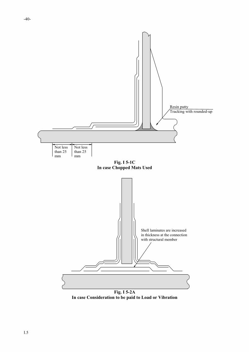
-40-
I.5
Resin putty
Tracking with rounded-up
Not lessthan 25mm
Not lessthan 25mm
Fig. I 5-1C
In case Chopped Mats Used
Shell laminates are increased
in thickness at the connection
with structural member
Fig. I 5-2A
In case Consideration to be paid to Load or Vibration

-41-
I.5
Plastic foam, etc. is inserted
between structural member
and laminates
Mat-overlay
Mat-in
Fig. I 5-2B
Standard Form of T-Joints
Filled up with resin putty, etc.
Fig. I 5-2C
Standard Form of T-Joints
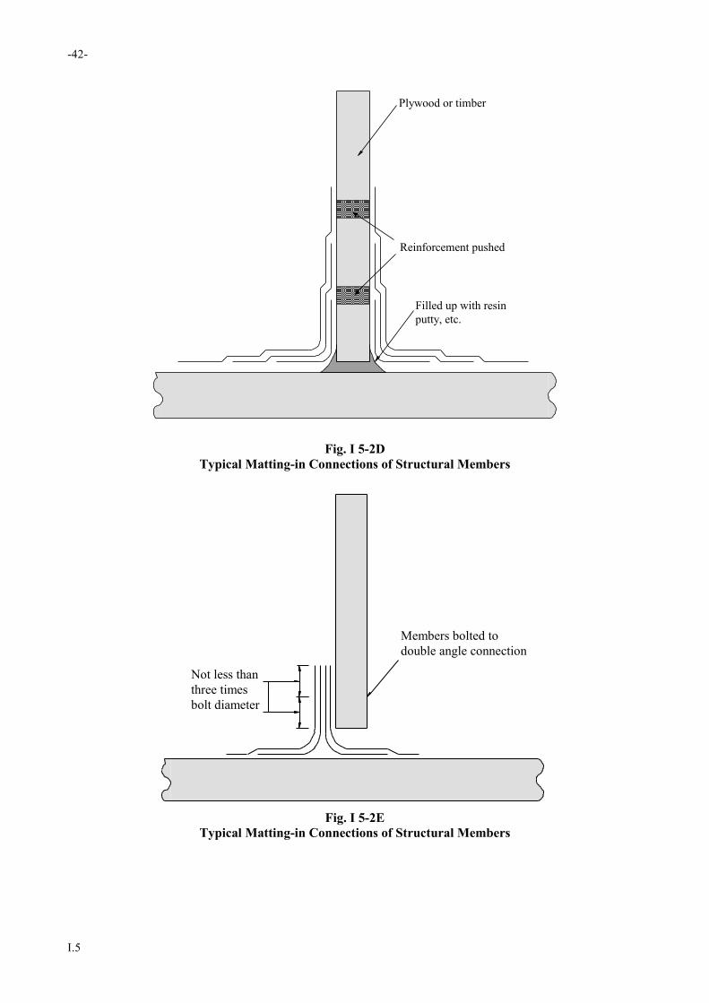
-42-
I.5
Plywood or timber
Reinforcement pushed
Filled up with resin
putty, etc.
Fig. I 5-2D
Typical Matting-in Connections of Structural Members
Members bolted to
double angle connection
Not less than
three times
bolt diameter
Fig. I 5-2E
Typical Matting-in Connections of Structural Members
RULES AND REGULATIONS FOR THE
CONSTRUCTION AND CLASSIFICATION OF
SHIPS OF FIBREGLASS REINFORCED
PLASTICS 2017
PART II – HULL CONSTRUCTION
April 2017

RULES AND REGULATIONS FOR THE
CONSTRUCTION AND CLASSIFICATION OF SHIPS
OF FIBREGLASS REINFORCED PLASTICS
PART I GENERAL REQUIREMENTS 2017
PART II HULL CONSTRUCTION 2017
PART III EQUIPMENT AND FITTINGS 2017
PART IV MACHINERY INSTALLATIONS 2017
PART V ELECTRICAL INSTALLATION 2017

List of major changes in Part II from 1998 edition
12.1.3 Amend No.1

RULES AND REGULATIONS FOR
THE CONSTRUCTION AND CLASSIFICATION OF SHIPS OF
FIBREGLASS REINFORCED PLASTICS
2017
PART II
HULL CONSTRUCTION
CONTENTS
Chapter 1 Shell Laminates............................................................................................................................ 1
1.1 Construction and Arrangement ................................................................................................................... 1 1.2 Scantlings .................................................................................................................................................... 1 1.3 Weight of Fibreglass Reinforcements and Thickness of Laminates ............................................................ 2 1.4 Scantling Reduction for Service Restriction ships ...................................................................................... 3
Chapter 2 Longitudinal Strength ................................................................................................................. 5
2.1 Application.................................................................................................................................................. 5 2.2 Section Modulus ......................................................................................................................................... 5 2.3 Moment of Inertia ....................................................................................................................................... 5 2.4 Calculation of Section Modulus .................................................................................................................. 5 2.5 Continuity of Strength Materials................................................................................................................. 6
Chapter 3 Shell Laminates............................................................................................................................ 7
3.1 General ........................................................................................................................................................ 7 3.2 Keels ........................................................................................................................................................... 7 3.3 Shell Laminates for Midship Part ............................................................................................................... 8 3.4 Shell Laminates for End Parts ..................................................................................................................... 9 3.5 Side Shell Laminates in Way of Superstructures ...................................................................................... 10 3.6 Local Strengthening of Shell Laminates ................................................................................................... 10
Chapter 4 Decks ........................................................................................................................................... 14
4.1 General ...................................................................................................................................................... 14 4.2 Minimum Thickness of Deck Laminates .................................................................................................. 14 4.3 Local Compensation of Decks .................................................................................................................. 15
Chapter 5 Frames ........................................................................................................................................ 17
5.1 General ...................................................................................................................................................... 17 5.2 Construction .............................................................................................................................................. 17

5.3 Spacing of Frames .................................................................................................................................... 17 5.4 Transverse System .................................................................................................................................... 17 5.5 Longitudinal System ................................................................................................................................. 18 5.6 Hat-type Construction ............................................................................................................................... 19
Chapter 6 Bottom Construction ................................................................................................................. 20
6.1 General ...................................................................................................................................................... 20 6.2 Center Girders ........................................................................................................................................... 20 6.3 Side Girders .............................................................................................................................................. 21 6.4 Transverse System .................................................................................................................................... 21 6.5 Longitudinal System ................................................................................................................................. 22 6.6 Double Bottoms ........................................................................................................................................ 22 6.7 Forward Strengthened Bottom .................................................................................................................. 24 6.8 Hat-Type Construction .............................................................................................................................. 24
Chapter 7 Under Deck Construction ......................................................................................................... 26
7.1 General ...................................................................................................................................................... 26 7.2 Spacing ..................................................................................................................................................... 26 7.3 Transverse System .................................................................................................................................... 26 7.4 Longitudinal System ................................................................................................................................. 27 7.5 Hat-Type Construction .............................................................................................................................. 28 7.6 Pillars ........................................................................................................................................................ 28
Chapter 8 Watertight Bulkheads ............................................................................................................... 30
8.1 Arrangements ............................................................................................................................................ 30 8.2 Construction of Watertight Bulkheads ...................................................................................................... 30
Chapter 9 Deep Tanks ................................................................................................................................. 33
9.1 General ...................................................................................................................................................... 33 9.2 Bulkhead Laminates.................................................................................................................................. 33 9.3 Additional Requirements .......................................................................................................................... 34
Chapter 10 Machinery Spaces .................................................................................................................... 36
10.1 General ...................................................................................................................................................... 36 10.2 Construction under Main Engines ............................................................................................................. 36 10.3 Auxiliary Machinery Foundations ............................................................................................................ 36
Chapter 11 Superstructures and Deckhouses ........................................................................................... 37
11.1 General ...................................................................................................................................................... 37 11.2 Construction .............................................................................................................................................. 37 11.3 Windows ................................................................................................................................................... 38
Chapter 12 Hatchway Openings, Machinery Openings and Other Deck Openings ............................. 40
12.1 General ...................................................................................................................................................... 40 12.2 Hatchway Openings .................................................................................................................................. 40 12.3 Machinery Openings ................................................................................................................................. 42 12.4 Other Openings ......................................................................................................................................... 42

-1-
II.1
Chapter 1
Shell Laminates
1.1 Construction and Arrangement
1.1.1 The requirements in this Part apply to ship‘s hull of a single skin construction consisting FRP shell and deck
laminates stiffened by a system of supporting members, or of a sandwich construction consisting FRP laminate on
either side of a core material which is assumed to be efficient bonded between skins and core that when a sandwich
panel is exposed to a lateral load the bending moments are carried by the skins and the shear forces by the core.
1.1.2 In single skin construction, hull laminates are generally supported by primary members in a collective term of
girder. Stiffener is a collective term for secondary supporting members. Other terms concerned are:
(a) Floor - bottom transverse girder
(b) Web frame and / web beam - side and deck transverse girder
(c) Stringer - side shell or bulkhead horizontal girder
(d) Vertical web - bulkhead girder
(e) Beam - deck stiffener
(f) Frame - side stiffener
(g) Longitudinal - bottom, side and deck stiffener
(h) Transverse - bottom transverse stiffener
1.1.3 Bottom and deck are normally to be longitudinally stiffened while the side shell may be longitudinally or
vertically stiffened. The longitudinal stiffeners are to be preferably continuous through transverse members and
supported by bulkhead and/or web frames. Ends of longitudinals are to be fitted with brackets or to be tapered out
beyond the point of support.
1.1.4 Sufficient transverse strength is to be provided by means of transverse bulkheads or girder structures. Web
frames are to be continuous around a cross section . i.e. floor, web frame and web beam are to be efficiently
connected. Longitudinal girders supporting the bottom panels and for docking purposes are to be carried continuously
through bulkheads. Engine girder and floor in way of thrust bearings are to be additionally provided with suitable local
reinforcements.
1.1.5 Structural continuity of the primary supporting members is to be maintained by fitting rounded brackets at the
conjunctions or tapered to zero at their ends. In superstructures and deckhouses, the exposed and internal bulkheads
are to be in line with bulkheads in the hull or effectively supported by girders, frame or pillars. The transition at the
break of superstructure is to be smooth without local discontinuities. Openings for doors and windows are to have
rounded corners and substantially strengthened along the edge.
1.2 Scantlings
1.2.1 The scantling required in the Rules are specified on the basis of the plastics, reinforced by chopped mats and
woven rovings, of which the mechanical properties excluding gel coat are to be in compliance with the followings:
(a) Tensile strength 110 N/mm2
(b) Modulus of tensile elasticity 7000 N/mm2
(c) Bending strength 160 N/mm2
-2-
II.1
(d) Modulus of bending elasticity 7200 N/mm2
1.2.2 The scantlings required may be modified as specified in the following, in case of a single skin construction
moulded by the FRP having the strength higher than those specified in 1.2.1.
(a) Thickness requirements may be multiplied by a factor obtained from the following formula:
(160/B)1/2
where:
B = Bending strength of the laminate obtained form the strength tests specified in 2.6 of Part I , in N/mm2
(b) Requirements of section modulus can be multiplied by a factor obtained from the following formula:
110/T
where:
T = Tensile strength of the laminate obtained form the strength tests specified in 2.6 of Part I , in N/mm2
1.2.3 The section modulus of the structure members required in the Rules are for those sections including effective
breadth on the laminate by 150 mm either side of the web.
1.2.4 In addition to the requirement of section modulus, stiffeners of hat-type construction either moulded to a
hollow form or moulded covering cores are to be of suitable proportions.
(a) The widths and heights of the stiffeners are not to be greater than the value obtained from the following
formula:
Width of crown : 20 tc K mm
Height of webs : 30 t K mm
where:
tc = Thickness of crown, in mm
t = Thickness of webs and flanges, in mm
K = 1 and may be taken as (Zr/Za)1/2
where:
Zr = Required section modulus for the stiffener, in cm3
Za = Actual section modulus of the stiffener, in cm3
(b) Where laminates forming hat-type stiffeners are bonded to the skin with flanges, the minimum lap of joint
is to be 0.2 height of the stiffener but not less than 50 mm and need not to be greater than 6t.
(c) The core for moulding of stiffeners may be reckoned in the strength at the discretion of the Society.
1.2.5 In design of a sandwich construction, the scantlings of inner and outer skin of FRP laminates are to be
determined by the modulus of bending elasticity obtained from the material test. The thickness ratio of outer and inner
layer is not to be less than 0.8, otherwise, the scantlings are subject to special consideration.
1.2.6 The core composing a sandwich panel is to be, as a rule, formed by one layer. The thickness of the core is not
to be larger than 25 mm, except for those core of special composition and design, the thickness may be increased at the
discretion of the Society. The core may be reckoned in the strength where the material test involving joint of cores are
included.
1.3 Weight of Fibreglass Reinforcements and Thickness of Laminates
1.3.1 Thickness of laminates per ply of chopped mats or woven rovings may be determined by following formula:

-3-
II.1
mm1000
W
1000
W
G10
W
R
g
G
g
R
g
where:
Wg = Weight per unit area of chopped mats or woven rovings, in g/m2
G = Glass content of laminate, ratio in weight, in %
R = Specific gravity of cured resin
G = Specific gravity of chopped mats or woven rovings
1.3.2 The glass content (G) specified in the preceding formula is preferable to be the value per ply for the actual
laminates. However, it may be taken as the mean glass content of the whole laminates.
1.3.3 In calculating the thickness of laminates, specific gravity of chopped mats or woven rovings (G) may be
taken as 2.5, if no special variation is to be considered. Specific gravity of cured resin (R) may be taken as 1.2, except
for those cases that fillers are used in order to make the resin heavier.
1.3.4 Calculation of the thickness of laminates with fibreglass reinforcements other than chopped mats and woven
rovings is to be in accordance with the properties specified by the material manufacturer at the discretion of the
Society.
1.3.5 The thickness of laminates obtained by the calculation is an average value for design purpose. Actual
laminate thicknesses have been known to vary as much as 15% over or under the average thickness without being
excessively resin rich or resin dry. Actual thicknesses of hull laminates are to be checked with design scantlings to the
satisfaction of the Society.
1.4 Scantling Reduction for Service Restriction ships
1.4.1 Application
(a) The requirements of this section are applicable to the ships intended to the following restricted service for
the purpose of reduction of structural scantling.
(b) Coasting service restriction means the service in the sea area within 20 nautical mile off the shore and a
passenger ship does not proceed in the course of its voyage more than 4 hours, or a cargo craft 8 hours at
operational speed from a place of refuge when fully laden.
(c) Sheltered water service restriction means the service in the sea area between the islands with a distance of
less than 10 nautical miles which form a comparatively good sheltered condition with a little wave; or
within 10 nautical miles off the shore, and a ship does not in the course of its voyage more than 2 hours at
operational speed from a place of refuge when fully laden.
(d) Smooth water service restriction means the service in the lake, dam or inside harbour.
1.4.2 Reductions of Scantlings
(a) The scantlings of structural members may be reduced by the ratios given in Table II 1-1 in relation to the
requirements in the relevant Chapters.
(b) Reductions of scantlings of members other than given in Table II 1-1 may be made at the discretion of the
Society.
(c) The scantlings of the deck structural members supporting deck cargoes, inner bottom structural members
supporting heavy cargoes and deep tank structural members are not to be reduced from the values specified
in the relevant Chapters, notwithstanding the provisions in (a) and (b).

-4-
II.1
Table II 1-1
Scantlings Reduction to Structural Members
Items Coasting service Sheltered water
service
Smooth Water
service
Longitudinal strength 5% 7.5% 10%
Bottom and shell platings (including keels) 5% 7.5% 10%
Weather deck platings if designed not based on cargo load 5% 7.5% 10%
Section modulus of bottom and shell internal members 10% 15% 20%
Section modulus of deck internal members 10% 12.5% 15%
Thickness of inner bottom 10% 15% 20%
Section modulus of inner bottom 10% 15% 20%
Thickness and section modulus of superstructure and deckhouse 5% 7.5% 10%

-5-
II.2
Chapter 2
Longitudinal Strength
2.1 Application
For ship of ordinary hull form with length not more than 20 m and L/D less than 12, the longitudinal strength is
normally satisfied for scantling calculated from local strength requirements specified in the pertinent provisions of the
Rules.
2.2 Section Modulus
The section modulus of the hull at midship is not to be less than the value obtained from the following formula:
SM = CL2Bw(Cb + 0.7) cm3
where:
C = Coefficient, obtained from the formula, 0.4L + 36, with a minimum value of 44
Bw = Horizontal distance between the outside of side shell laminates at the designed maximum load line, in m
Cb = Block coefficient at the designed maximum load line
2.3 Moment of Inertia
The moment of inertia of the athwartship section at midship is not to be less than the value obtained from the
following formula:
I = 4.2 ZL cm4
where:
Z = Section modulus of the athwartship section specified in 2.2, in cm3
2.4 Calculation of Section Modulus
The calculation of section modulus of the athwartship section is to be comply with the requirements specified in the
following 2.4.1 to 2.4.4:
2.4.1 Below the strength deck, all longitudinal members which are considered as continuous for 0.4L amidships are
to be included in the calculation. However, above the strength deck longitudinal members which are considered
effective to the longitudinal strength of the ship may be included in the calculation.
2.4.2 The section modulus at the strength deck is to be calculated by dividing the moment of inertia corresponding
to the horizontal neutral axis of the athwarship section by the vertical distance from the neutral axis to the top of
strength deck beam at side, or the top of the longitudinal members above the strength deck in case of which included
in the calculation in accordance with the provision specified in 2.4.1. The section modulus at the bottom is to be
calculated by diving the above-mentioned moment of inertia by the vertical distance from the neutral axis to the base
point of D, or the bottom of keel provided that the keel is of hat-type construction.
2.4.3 If timbers or structural plywoods were included in such longitudinal calculation the sectional area in question
are to be multiplied by the ratio of the modulus of tensile elasticity of the relevant material to that of the FRP. If the
ratio of timbers, structural plywoods and other core materials reckoned in the longitudinal strength may be generally
specified as follows:
(a) Pine and lauan-1.0
(b) Plywoods-0.8

-6-
II.2
(c) Other core materials - the value obtained by the tests specified in 2.5 of Part I of the Rules.
2.4.4 If core materials of sandwich laminates or core materials moulding were included in such longitudinal
strength calculation, the sectional area in question shall be multiplied by the ratio of the modulus of tensile elasticity of
the pertinent core material to that of the FRP is to be included in the calculation.
2.4.5 Provided that any material mentioned in 2.4.3 and 2.4.4 was reckoned in the longitudinal strength calculation
it is to be provided with scarf joints of which the joint length is to be not less than 6 times the thickness as usual.
2.5 Continuity of Strength Materials
Longitudinal strength members are to be of such a construction as to maintain good continuity of strength.
-7-
II.3
Chapter 3
Shell Laminates
3.1 General
3.1.1 Application
The scantlings of shell laminates specified in this chapter are applied to single skin construction or sandwich
construction.
3.1.2 Small Boats
Small boats less than 12 meters in length may be built as unstiffened, i.e., there is no stiffener added to shell laminates.
In this type of hull, the scantling of bottom and side laminates is to be suitably increased, subject to specially
consideration by the Society. The necessary stiffeners are to be provided in way of the internal assemblies, such as
tanks, fuel tanks, cabin bulkheads, etc.
3.2 Keels
3.2.1 The keels are to be continuous from fore end to after end as far as practicable.
3.2.2 The width and thickness of keel laminates over the whole length of the ship are not to be less than the value
obtained from the following formulae.
(a) Plate Keels (Fig. II 3-1)
t = 1.5 tb mm
W = B/10 m
where:
tb = Thickness of bottom shell plating as specified in 3.3.2 and 3.4.2
W = Width of keel, in m
B = Breadth of vessel, in m
(b) Vertical Keels and Skegs (Fig. II 3-2)
t = 1.5 tb mm
W = 0.25H mm
where:
tb = Thickness of bottom shell plating, in mm, as specified in 3.3.2
W = Width of extension of keel or skeg thickness t onto the bottom of the vessel, in mm
H = Maximum depth of keel or skeg, in (mm)
(c) Ballasted Vertical Keels (Fig. II 3-3)
t = 2.0 tb H1 = 0.5W1
where:
tb = Thickness of bottom shell plating as specified in 3.3.2,in mm
H1 = Height of extension of thickness of bottom of keel up each side of the keel, in mm
W1 = Width of bottom of keel laminate or 250 mm, whichever is greater, in mm
-8-
II.3
3.3 Shell Laminates for Midship Part
3.3.1 Side Shell Laminates of Single Skin Construction
The thickness of side shell laminates, of single skin construction is not to be less than the value obtained from the
following formula.
t = 14.6S d + 0.026L mm
where:
S = Spacing of frames, in m
3.3.2 Bottom Shell Laminates of Single Skin Construction
The thickness of bottom shell laminates, is not to be less than the value obtained from the following formula.
t = 15.3 S d + 0.026L mm
where:
S = Spacing of frames, in m
3.3.3 Shell Laminates of Sandwich Construction
(a) The aggregated thickness of inner skin, outer skin and core of sandwich construction is not to be less than
the value obtained from the following formula, whichever is greater.
C1S(d + 0.026L) mm; or
C2t mm
where:
C1 = Coefficient obtained from the formula: C3
a
a = Shearing strength of sandwich laminates obtained from the test specified in 2.5 of Part I ,
in MPa.
S = Spacing of frames, in m
C2 and C3 = As given in Table II 3-1. For the intermediate values of and , C2 and C3 are to be
obtained by linear interpolation
t = Thickness of single skin construction specified in 3.3.1 or 3.3.2, in mm
Table II 3-1
Value of C2 and C3
β 0.2 0.3 0.4 0.5 0.6 0.7 0.8 0.9 1.0
C2 α =0.8 1.57 1.38 1.27 1.20 1.16 1.13 1.11 1.11 1.07
α =1.0 1.49 1.32 1.21 1.15 1.12 1.09 1.07 1.05 1.04
C3 20.7 21.5 22.2 22.8 23.4 24.0 24.5 24.9 25.4
where:
α = The ratio of outer skin thickness and/or inner skin thickness dividing the lesser one by the greater one
β = The ratio of dividing total thickness of outer skin and inner skin by the thickness of core
(b) The respective thickness of inner skin and outer skin of shell laminate of sandwich construction is ,
notwithstanding the requirements in the preceding (a), not to be less than the value obtained from the
following formula. In no case, however, is it to be less than 2.4 mm:
t = 73.5 3 C4S4(d + 0.026L)4 mm
-9-
II.3
where:
C4 = Coefficient obtained from the following formula:
4
c
c
c
1
E
E
t
1
f
E = Modulus of bending elasticity of inner skin or outer skin specified in 2.6 of Part I, in N/mm 2
Ec = Modulus of compressive elasticity of core specified in 2.5 of Part I, in N/mm2
c = Compressive strength of core specified in 2.5 of Part I, in MPa
tc = Thickness of core, in mm
S = Spacing of frames, in m
3.4 Shell Laminates for End Parts
3.4.1 Thickness of Shell Laminates for End Parts
(a) The thickness of shell laminates of single skin construction may be gradually reduced beyond the midship
part to 0.85 times the thickness of shell laminates amidships for end parts.
(b) Shell laminates of sandwich construction beyond the midship part are to be of the same construction as that
for the midship part.
(c) For the portion subject to local loads such as propeller load, etc., the shell laminates are to be properly
strengthened.
3.4.2 Strengthened Forward Bottom
(a) The strengthened forward bottom is the part of flat bottom forward from the position specified in the
following (i) or (ii). The flat bottom is the bottom of which slope measured at the respective athwartship
sections (See Fig. II 3-4) is not more than 15 degrees.
(i) Where V/ L is not more than 1.5:
0.25L from the fore end,
(ii) Where V/ L exceeds 1.5:
0.3L from the fore end.
Where V is the maximum speed in knots which the ship with clean bottom can attain at the maximum
continuous output on calm sea in loading condition corresponding to the designed maximum load line.
(b) The thickness of shell laminates at the strengthened forward bottom of single skin construction is not to be
less than the value obtained from the following formula:
t = CS L mm
where:
C = Coefficient given in Table II 3-2. However, for the intermediate values ofα , C is to be
obtained by linear interpolation.
S = Spacing of frames, or spacing of girders or shell longitudinals, whichever is smaller, in m.
α = Spacing of frames, or spacing of girders or shell longitudinals, whichever is greater, in m,
divided by S.
Table II 3-2
Value of C
α 1.0 1.2 1.4 1.6 1.8 2.0 and above
C 5.20 5.80 6.18 6.42 6.55 6.61
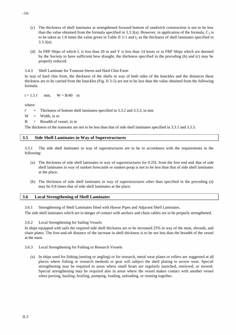
-10-
II.3
(c) The thickness of shell laminates at strengthened forward bottom of sandwich construction is not to be less
than the value obtained from the formula specified in 3.3.3(a). However, in application of the formula, C3 is
to be taken as 1.8 times the value given in Table II 3-1 and t as the thickness of shell laminates specified in
3.3.3(a).
(d) In FRP Ships of which L is less than 20 m and V is less than 14 knots or in FRP Ships which are deemed
by the Society to have sufficient bow draught, the thickness specified in the preceding (b) and (c) may be
properly reduced.
3.4.3 Shell Laminate for Transom Sterns and Hard Chin Form
In way of hard chin form, the thickness of the shells in way of both sides of the knuckles and the distances these
thickness are to be carried from the knuckles (Fig. II 3-5) are not to be less than the value obtained from the following
formula.
t = 1.5 t' mm, W = B/40 m
where:
t' = Thickness of bottom shell laminates specified in 3.3.2 and 3.3.3, in mm
W = Width, in m
B = Breadth of vessel, in m
The thickness of the transoms are not to be less than that of side shell laminates specified in 3.3.1 and 3.3.3.
3.5 Side Shell Laminates in Way of Superstructures
3.5.1 The side shell laminates in way of superstructures are to be in accordance with the requirements in the
following:
(a) The thickness of side shell laminates in way of superstructures for 0.25L from the fore end and that of side
shell laminates in way of sunken forecastle or sunken poop is not to be less than that of side shell laminates
at the place.
(b) The thickness of side shell laminates in way of superstructures other than specified in the preceding (a)
may be 0.8 times that of side shell laminates at the place.
3.6 Local Strengthening of Shell Laminates
3.6.1 Strengthening of Shell Laminates fitted with Hawse Pipes and Adjacent Shell Laminates.
The side shell laminates which are in danger of contact with anchors and chain cables are to be properly strengthened.
3.6.2 Local Strengthening for Sailing Vessels
In ships equipped with sails the required side shell thickness are to be increased 25% in way of the mast, shrouds, and
chain plates. The fore-and-aft distance of the increase in shell thickness is to be not less than the breadth of the vessel
at the mast.
3.6.3 Local Strengthening for Fishing or Research Vessels
(a) In ships used for fishing (netting or angling) or for research, metal wear plates or rollers are suggested at all
places where fishing or research methods or gear will subject the shell plating to severe wear. Special
strengthening may be required in areas where small boats are regularly launched, retrieved, or stowed.
Special strengthening may be required also in areas where the vessel makes contact with another vessel
when pursing, hauling, brailing, pumping, loading, unloading, or running together.
-11-
II.3
(b) In way of trawl gallows the minimum thickness of the side shell plating is to be 30% greater than the
thickness of the side shell plating obtained from 3.3.1 and 3.3.3. A vessel fitted with two or more gallows
on each side or one side only, the minimum thickness of the side shell plating between the gallows is to be
20% greater than the thickness of the side shell plating obtained from 3.3.1 and 3.3.3. Half-round metal rub
bars are to be installed at the top of the bulwark, the top of the sheerstrake, and the designed waterline.
These bars are to extend from not less than 0.0225L forward of the forward leg of each gallows to not less
than 0.045L aft of said gallows leg. Additional half-round rub bars are to be installed vertically or
diagonally between the longitudinal rub bars in such a manner that the shell plating cannot be subject to
abrasion by the gear being handled by the gallows.
(c) Vessels with Stern Trawls
The minimum thickness of the stern trawl chute is to be 30% greater than the thickness of the side shell
plating obtained from 3.3.1 and 3.3.3. The minimum thickness of the chute sides is to be 10% greater than
the thickness of the side shell plating obtained from 3.3.1 and 3.3.3. Metal wear plates are suggested at
parts of the chute bottom and sides subject to severe wear.
3.6.4 Reinforcements
Reinforcements are to be made for large openings in the shell plating where required to maintain the longitudinal and
transverse strength of the hull. All openings are to have well-rounded corners. Cargo and gangway openings are to be
kept well clear of other discontinuities in the hull girder. Around hawse pipes, metal wear plates, of sufficient breadth
to prevent damage from the flukes of stockless anchors, are to be fitted. Each portlight, where fitted, is to have its
upper edge a minimum of two times its diameter, or in the case of the rectangular port, two times its height, below the
edge of the deck above it. Exposed edges of laminates are to be sealed with resin.
3.6.5 Structure Interruptions
The side plating of superstructures, including forecastles and poops, is to extend beyond the ends of the
superstructures in such fashions to provide long, gradual tapers. Gangways, large freeing ports, and other sizable
openings in the shell or bulwarks are to be kept clear of the structure. Any holes that must unavoidably be cut in the
shell adjacent to the interruptions are to be kept as small as possible and are to be circular or oval in form.
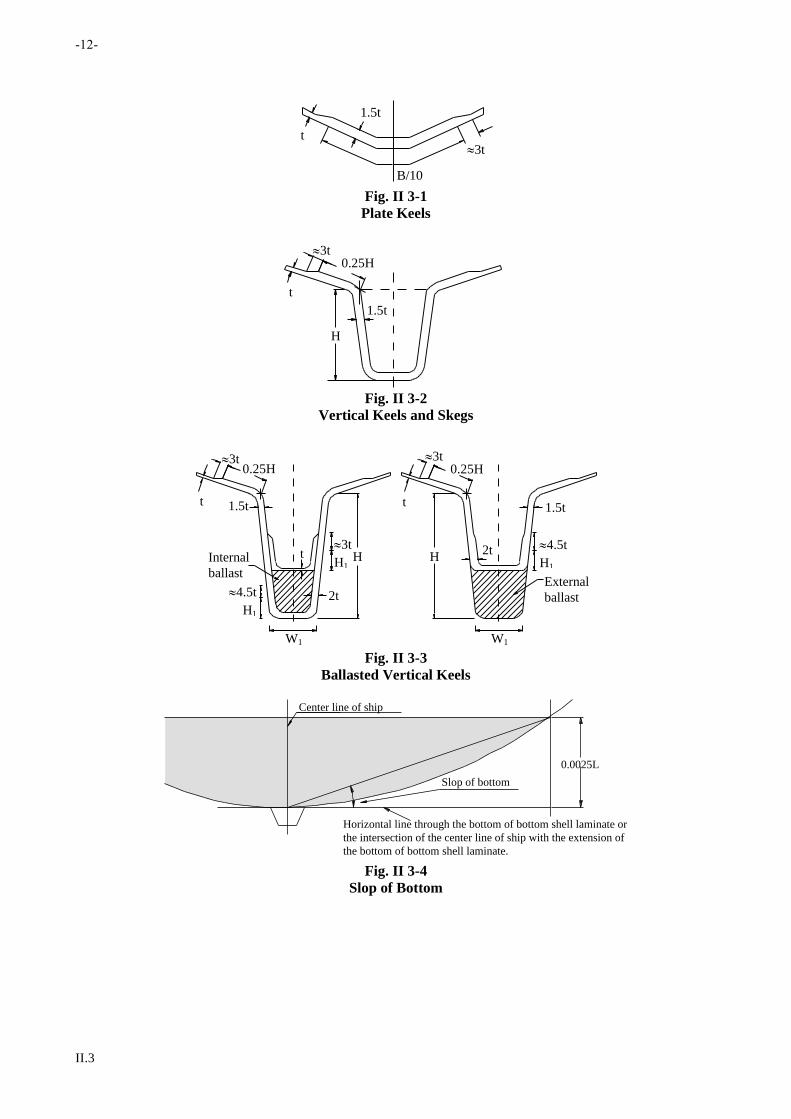
-12-
II.3
t
B/10
3t
1.5t
Fig. II 3-1
Plate Keels
0.25H
H
1.5t
3t
t
Fig. II 3-2
Vertical Keels and Skegs
W1W1
H1
4.5tExternal
ballast
Internal
ballast
1.5t1.5t
0.25H0.25H3t3t
t
2tt HH
2t
t
H1
4.5t
H1
3t
Fig. II 3-3
Ballasted Vertical Keels
0.0025L
Horizontal line through the bottom of bottom shell laminate or
the intersection of the center line of ship with the extension of
the bottom of bottom shell laminate.
Slop of bottom
Center line of ship
Fig. II 3-4
Slop of Bottom

-13-
II.3
3t
3t
B/40
B/40
t
1.5t
Fig. II 3-5
Reinforcement for Shell Knuckles

-14-
II.4
Chapter 4
Decks
4.1 General
4.1.1 Application
(a) The requirements in this chapter are applied to the construction and scantlings of decks moulded with FRP.
The decks such as wooden decks which are composed of other materials than FRP are to be in accordance
with the discretion of the Society.
(b) The construction and scantlings of decks specified in this chapter are applied to single skin construction or
sandwich construction.
4.1.2 Watertightness of Decks
The construction of decks is to be made watertight except being specially approved by the Society.
4.1.3 Continuity of Decks
Where the upper decks change in level, the change is to be accomplished by gradually sloping the decks, or each of
structural members which form decks is to be extended and to be effectively connected together by suitable means.
4.2 Minimum Thickness of Deck Laminates
4.2.1 Thickness of Deck Laminates of Single Skin Construction
(a) The thickness of upper deck laminates for 0.4L amidships, is not to be less than the value obtained from the
following formula:
(i) For longitudinal framing system
t = 14.3S h mm
(ii) For transverse framing system
t = 17.4S h mm
where:
S = Spacing of deck longitudinals or transverse beams, in m
h = As specified in 4.2.3, in m
(b) The thickness of upper deck laminates for outside of 0.4L amidships and that of other deck laminates are
not to be less than the value obtained from the following formula:
t = 12.4S h mm
where:
S = Spacing of deck longitudinals or transverse beams, in m
h = As specified in 4.2.3, in m
4.2.2 Deck Laminates of Sandwich Construction
(a) The aggregated thickness of inner skin, outer skin and cores of sandwich construction is not to be less than
the value obtained from the following formula whichever is greater:
t = C1Sh mm
t = C2t mm

-15-
II.4
where:
C1 and C2 = As specified in 3.3.3(a) of this Part
S = Spacing of deck longitudinals or transverse beams, in m
h = As specified in 4.2.3, in m
t = Thickness of deck laminates constructed specified in 4.2.1, in mm
(b) The respective thickness of the inner skin and outer skin of sandwich construction are, notwithstanding the
requirements in the preceding (a), not to be less than the value obtained from the following formula. In no
case, however, is it to be less than 2.4 mm.
t = 73.5 3 C4(Sh)4 mm
where:
C4 = As specified in 3.3.3(b)
S = Spacing of deck longitudinals or transverse beams, in m
h = As specified in 4.2.3, in m
4.2.3 Deck Head
(a) Deck head h intended to carry cargoes, etc. is to be as specified in the following:
(i) For decks intended to carry cargoes and stores, h is to be 0.72 times the tween deck height at side
from the deck to the deck immediately above it (m), or cargo weight per unit area of the deck
converting into waterhead (m), whichever is greater.
(ii) Where cargoes are intended to be carried on the weather deck, h is to be cargo weight per unit area
of the deck converting into waterhead (m) or the value stipulated in (b), whichever is greater.
(iii) For decks intended to carry cargoes which weight is considerably light, h may be suitably modified.
(b) For decks without loading cargoes, the deck load h is to be specified as follows:
(i) For exposed freeboard decks and first tier superstructure decks afore 0.3L from the fore end:
h = 0.027L + 0.76 m
(ii) For freeboard deck inside enclosed superstructures, and exposed first tier superstructures deck abaft
0.3L from the fore end:
h = 0.010L + 0.62 m
(iii) For other superstructure decks not specified in (i) & (ii):
h = 0.017L + 0.47 m
(iv) For enclosed accommodations:
h = 0.47 m
(c) In case where fishes carried on deck in fishing vessels, the deck load h is to be the value specified in
4.2.3(b)(i) and (ii) or the value obtained from the following formula, whichever is the greater.
h = 0.023L + 1 m
4.3 Local Compensation of Decks
4.3.1 Compensation for Large Openings
(a) Deck laminated in way of the corners of large openings are to be suitably increased in thickness.

-16-
II.4
(b) Corners of openings are to be suitably rounded.
4.3.2 Location of Openings
The distance between the ship side or hatch side and the opening is not to be less than 1.5 times the diameter of the
opening. Where, however the distance is necessary made less than this specified value, suitable compensation is to be
provided.
4.3.3 Decks in Danger of Abrasion
Deck laminates under abrasion by heavy loads, etc. are to be suitably protected from abrasion by means of increasing
thickness or providing with coverings.
4.3.4 Decks carrying Heavy Loads
The portion of deck laminates where heavy load such as deck machinery or others installed is to be increased in
thickness or to be suitably reinforced.
4.3.5 Deck to Hull Connection
(a) All connections are to be lapped and bolted unless otherwise specially approved. Connections differing
from those shown are to be specially considered by the Society.
(b) Where flanges are used, the hull flanges are to be equal in thickness to the hull laminates and the deck
flanges are to be equal in thickness to the deck laminates.
(c) Faying surfaces are to be set in bedding compound polyester putty, or other approved material.
(d) FRP bonding angles, where used, are to have flanges that are at least one-half as thick as the hull or deck
laminate, whichever is the thicker.
(e) Widths of overlaps, metal bolt diameters metal bolt spacing and width of the flanges of FRP bonding
angles are to be in accordance with the following formulae. Intermediate values may be obtained by linear
interpolation.
(i) Metal bolt diameters and spacing
d = 0.417 L + 2.75 mm
Sb= 4.24L + 114 mm
where:
d = Bolt diameter, in mm
Sb= Bolt spacing, in mm
(ii) Widths of overlaps and widths of flanges of FRP bonding angles.
b = 4.17L + 25 mm
(f) Each connection is to be protected by a guard, molding, fender or rail cap of metal, wood, rubber, plastic,
or other approved material.

-17-
II.5
Chapter 5
Frames
5.1 General
5.1.1 Application
(a) The requirements in this chapter are applied to the construction and scantlings of transverse or longitudinal
frames moulded with FRP.
(b) For FRP vessels with especially long holds or with especially large hatch openings, the transverse stiffness
of the hull is to be suitably increased by increasing the scantlings of frames or by providing web frames
additionally.
(c) In vessels equipped with sails, web frames or transverse bulkheaded are to be provided in way of masts.
5.1.2 Frames in Way of Deep Tanks
The strength of frames in way of deep tanks is not to be less than the section modulus required for the stiffeners on
deep tank bulkheads.
5.2 Construction
5.2.1 Construction of Frames
(a) Frames are so constructed as to avoid lateral buckling.
(b) Where the length of ship is small, corrugated side shell laminates may be adopted in lieu of normal framing
construction.
5.2.2 Core material
(a) Timbers used for cores are to be well seasoned, free from sapwood and treated with a suitable wood
preservative, if necessary. Care is to be taken to prevent the timbers laminated in FRP from dry rot.
(b) Plastic foams used for cores are to be non-hygroscopic.
(c) The requirement of this section also apply to other chapters.
5.3 Spacing of Frames
5.3.1 The standard spacing of frames is 500 mm for transverse system or 600 mm for longitudinal system.
5.3.2 The spacing of frames afore 0.2L from the fore end is not to exceed 500 mm.
5.3.3 Where the spacing of frames is 750 mm or over, special considerations are to be given to the construction and
scantlings of the primary hull structural members.
5.4 Transverse System
5.4.1 Transverse Frames
(a) The section modulus of transverse frames abaft 0.15L from the fore end is not to be less than the value
obtained from the following formula:
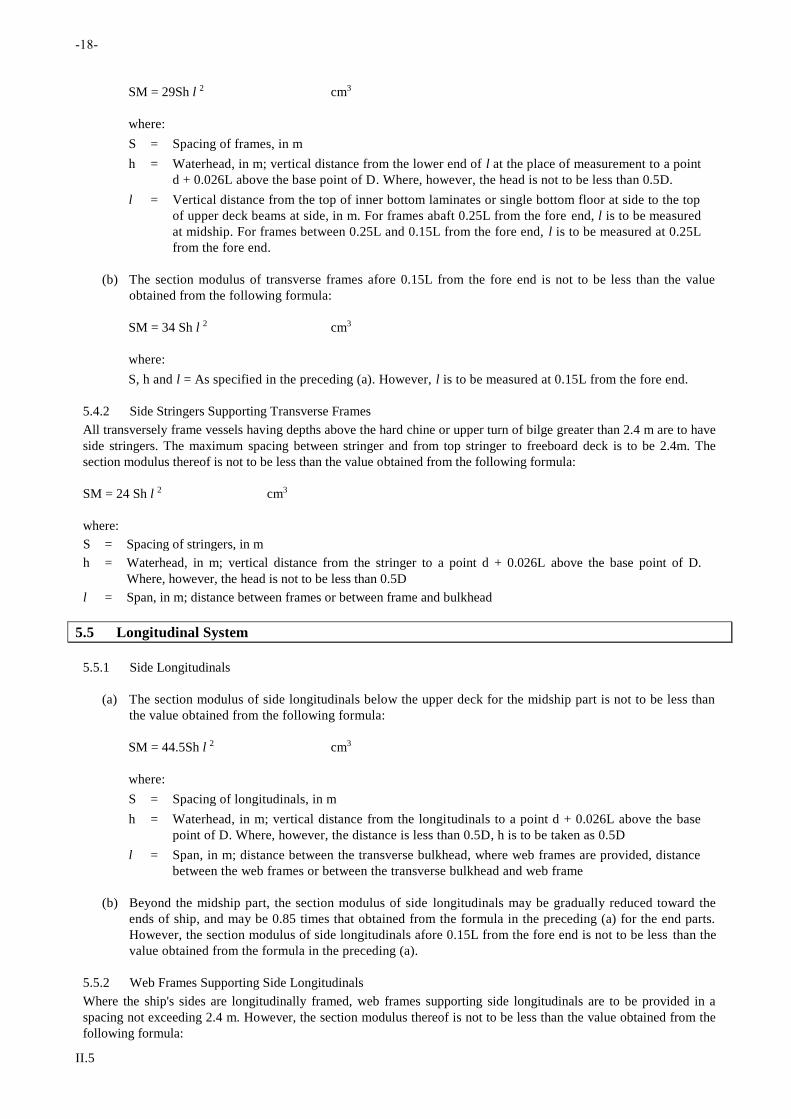
-18-
II.5
SM = 29Sh l 2 cm3
where:
S = Spacing of frames, in m
h = Waterhead, in m; vertical distance from the lower end of l at the place of measurement to a point
d + 0.026L above the base point of D. Where, however, the head is not to be less than 0.5D.
l = Vertical distance from the top of inner bottom laminates or single bottom floor at side to the top
of upper deck beams at side, in m. For frames abaft 0.25L from the fore end, l is to be measured
at midship. For frames between 0.25L and 0.15L from the fore end, l is to be measured at 0.25L
from the fore end.
(b) The section modulus of transverse frames afore 0.15L from the fore end is not to be less than the value
obtained from the following formula:
SM = 34 Sh l 2 cm3
where:
S, h and l = As specified in the preceding (a). However, l is to be measured at 0.15L from the fore end.
5.4.2 Side Stringers Supporting Transverse Frames
All transversely frame vessels having depths above the hard chine or upper turn of bilge greater than 2.4 m are to have
side stringers. The maximum spacing between stringer and from top stringer to freeboard deck is to be 2.4m. The
section modulus thereof is not to be less than the value obtained from the following formula:
SM = 24 Sh l 2 cm3
where:
S = Spacing of stringers, in m
h = Waterhead, in m; vertical distance from the stringer to a point d + 0.026L above the base point of D.
Where, however, the head is not to be less than 0.5D
l = Span, in m; distance between frames or between frame and bulkhead
5.5 Longitudinal System
5.5.1 Side Longitudinals
(a) The section modulus of side longitudinals below the upper deck for the midship part is not to be less than
the value obtained from the following formula:
SM = 44.5Sh l 2 cm3
where:
S = Spacing of longitudinals, in m
h = Waterhead, in m; vertical distance from the longitudinals to a point d + 0.026L above the base
point of D. Where, however, the distance is less than 0.5D, h is to be taken as 0.5D
l = Span, in m; distance between the transverse bulkhead, where web frames are provided, distance
between the web frames or between the transverse bulkhead and web frame
(b) Beyond the midship part, the section modulus of side longitudinals may be gradually reduced toward the
ends of ship, and may be 0.85 times that obtained from the formula in the preceding (a) for the end parts.
However, the section modulus of side longitudinals afore 0.15L from the fore end is not to be less than the
value obtained from the formula in the preceding (a).
5.5.2 Web Frames Supporting Side Longitudinals
Where the ship's sides are longitudinally framed, web frames supporting side longitudinals are to be provided in a
spacing not exceeding 2.4 m. However, the section modulus thereof is not to be less than the value obtained from the
following formula:

-19-
II.5
SM = 32Shl 2 cm3
where:
S = Spacing of web frames, in m
h and l = As specified in 5.4.1(a)
5.6 Hat-type Construction
5.6.1 Typical Configuration
The typical configurations of such sections are shown in Fig. II 5-1. Such configurations are also applicable to similar
construction specified in the Rules.
5.6.2 Requirement
With respect to the scantling of frames of hat-type construction, the requirements in 1.2.4 of this Part, in addition to
the requirements in this chapter, are to be complied with.
Form
(a) Premolded FRP form
Bonding
angle
(b) Premolded stiffener
(c) Encapsulated wood or plywood
Fig. II 5-1

-20-
II.6
Chapter 6
Bottom Construction
6.1 General
6.1.1 Application
(a) The requirements of this chapter are applied mainly to the single bottoms supported by the transverse
system where bottom transverses or transverse bulkheads and girders to be provided, or the longitudinal
system where floors or transverse bulkheads and bottom longitudinals to be provided.
(b) Where bottoms are constructed in double bottom partially or wholly, the structural members of double
bottoms are to be complied with the requirements of 6.6 of this chapter.
(c) Longitudinal structural members such as bulkheads, engine bed girders, vertical keels and skegs may be
considered as girders.
6.1.2 Drain and Air Holes
Drain holes are to be molded or cut in the bottom structures and non-tight bulkheads to assure the free drainage of
bilges to suction wells. The edges of the holes are to sealed with proper resin. Drain and air holes are to be provided in
all non-watertight members of double bottom with the same method to ensure that liquid or air does not remain
stagnated in any part of tanks.
6.1.3 End Construction
Unless otherwise specifically approved, the end construction of girders, web frames, frames and longitudinals are to be
attached to their supporting members.
6.2 Center Girders
6.2.1 Arrangement
(a) Center girders are to extend from the collision bulkhead to the aft peak bulkhead as far as practicable.
(b) For ships with hat-type keel of suitable height, the center girder may be omitted.
6.2.2 Construction and Scantlings
(a) The thickness of FRP laminated webs of center girders is not to be less than the value obtained from the
following formula. However, beyond the midship part, the thickness may be gradually reduced toward the
ends and it may be 0.8 times the midship value for the end:
t = 0.4L + 4.7 mm
(b) The thickness and breadth of the face plates are not to be less than the value obtained from the following
formula respectively. However, beyond the midship part, the sectional area of the face plates may be
gradually reduced toward the ends and it may be 0.8 times the midship value for the end:
t = 0.4L + 4.7 mm
b = 4L + 30 mm
(c) The webs of center girders are to extend to the top of bottom transverse floors.
6.2.3 Center girder in way of M/E
The thickness of webs and face plates of center girders in way of M/E are not to be less than 1.25 times the values
specified in the preceding 6.2.2(a) and (b) respectively.
-21-
II.6
6.3 Side Girders
6.3.1 Arrangement
Where the breadth of ship measured at the top of floors exceeds 4.8 m, side girders are to be arranged at a suitable
spacing.
6.3.2 Construction and Scantlings
(a) The thickness of webs of side girders for the midship part is not to be less than the value obtained from the
following formula. However, beyond the midship part, the thickness may be gradually reduced toward the
ends and it may be 0.8 times the midship value at the end:
t = 0.3L + 3.5 mm
(b) The thickness and breadth of face plates of side girders are not to be less than the values obtained from the
following formulae respectively. However, beyond the midship part, the sectional area may be gradually
reduced toward the ends and it may be 0.8 times the midship value at the end :
t = 0.3L + 3.5 mm
b = 3.2L + 24 mm
(c) The heights of side girders at their ends are to extend to the top of bottom transverse floors.
6.3.3 Side Girders in way of M/E
The thicknesses of webs and face plates of side girders in way of M/E are not to be less than the thicknesses of webs
and face plates of center girders specified in 6.2.3.
6.4 Transverse System
6.4.1 Arrangement and Scantlings of Floors
(a) Where transverse framing is adopted in the bottom construction, floors are to be fitted at each frame and
the section modulus of floors is not to be less than the value obtained from the following formula.
SM = 34Sh l 2 cm3
where:
S = Spacing of transverse floors, in m
h = Waterhead, in m; vertical distance from the middle of l to a point d + 0.026L above the base
point of D, where, however, h shall not less than 0.5D
l = Span, in m; distance between the girders
(b) Beyond 0.5L amidships, the section modulus of floor plates may be gradually reduced toward the ends and
it may be 0.8 times the value specified in the preceding (a) at the end. However, the floors in the
strengthened bottom forward are to be in accordance with the requirements in 6.7.2.
(c) The thickness of face plate provided on the upper edges of floors is not to be less than the thickness of web
of floor at the place.
(d) The section modulus of floors under the main engine seatings is not to be less than 1.5 times the value
specified in the preceding (a).
6.4.2 Floors Forming Part of Bulkheads
Floor forming part of bulkheads are to be in accordance with the requirements for watertight bulkheads in Chapter 8
and those for deep tanks in Chapter 9 in addition to those specified in this chapter.

-22-
II.6
6.5 Longitudinal System
6.5.1 Construction
Where longitudinal framing is adopted in the bottom construction, bottom longitudinals are to be fitted continuously
by penetrating floors or similar construction or to be attached to thereof so as to have sufficient fixing strength against
bending and tension.
6.5.2 Spacing of Bottom Longitudinals
The standard spacing of bottom longitudinals is 600 mm.
6.5.3 Section Modulus of Bottom Longitudinals
The section modulus of bottom longitudinals is not to be less than the value obtained from the following formula:
SM = 48 Sh l 2 cm3
where:
S = Spacing of longitudinals, in m
h = Waterhead, in m; vertical distance from the bottom longitudinals to a point d + 0.026L above the base point
of D. Where, however, the distance is not to be less than 0.5D
l = Span, in m; distance between the floors
6.5.4 Bottom Floors Supporting Bottom Longitudinals
Where longitudinal framing is adopted in the bottom construction, bottom floors supporting bottom longitudinals are
to be provided at a spacing not exceeding 2.4 m. The bottom floors are to be fitted at every web frame and the
scantlings are not to be less than the value specified in 6.4.1 of this chapter.
6.6 Double Bottoms
6.6.1 General
(a) Where bottoms are partially or wholly of double bottom construction, the scantlings of structural members
are to be in accordance with the requirements in 6.6.2 to 6.6.7 of this section.
(b) Bottom laminates under the sounding pipes are to be increased in thickness or to be protected against
damages due to striking of sounding rods by suitable means.
(c) The thickness of watertight girders and floors, and the scantlings of stiffeners attached to them are to be in
accordance with the respective requirements for the relevant girders and floors, and in addition, in
accordance with the requirements for deep tanks in Chapter 9.
(d) Cofferdams are to be provided in the double bottom between oil tanks and fresh water tanks used for living,
boiler feed water, etc., which may cause trouble when oil mixed therein.
(e) In transverse system, center girder and/or side girders, if necessary, solid floors or open floors are to be
provided. In longitudinal system, center girder and/or side girders, if necessary, solid floors are to be
provided.
6.6.2 Center Girders
(a) Webs of center girders are to extend the whole length of the bottom as far as practicable.
(b) The thickness of webs of center girders is to be in accordance with the requirements in 6.2.2.
6.6.3 Side Girders
(a) Where the breadth of ship measured at the top of floors exceeds 4.8 m, side girders are to be arranged at a
suitable spacing.
-23-
II.6
(b) The thickness of webs of side girders is to be in accordance with the requirements in 6.3.2.
6.6.4 Solid Floors
(a) Solid floors are to be provided at a spacing not exceeding 2.4 m.
(b) In addition to complying with the requirement in preceding (a), solid floors are to be provided at the
following locations:
(i) At each frame in main engine room, solid floors may, however, be provided at alternative frames
outside the engine bed.
(ii) Under thrust bed, if provided.
(iii) Under transverse bulkheads.
(iv) Forward bottom specified in 6.7.2
(c) The scantlings of floors are to be in accordance with the requirements in 6.4.1.
(d) Where floors are of single skin construction, stiffeners are to be provided on floors at a spacing not
exceeding 1.2 m.
(e) Lightening holes or manholes may be provided without effecting the strength of floor, and, if necessary,
suitable strength compensation is to be taken by increasing the floor depth or by other means.
(f) All tanks are to have access holes, and the nontight members in such tanks are to have lightening ho les,
sufficient in size and number to assure accessibility to all spaces of the tanks. Tank access covers are to be
metal or FRP, and secured to the tanks. The diameter of bolts or studs "d" are to be not less than 6.5 mm,
their spacing, center to center, is to be not more than 6d, and they are to be set in from the edges of the
covers a distance not less than 3d for FRP cover or 2d for steel cover. In cargo holds if no ceiling provided,
the covers are to be protected against damage caused by the cargo.
(g) Floor plates forming of bulkheads are to be in accordance with the requirements for watertight bulkheads in
Chapter 8 in addition to those in this chapter.
6.6.5 Open Floors
(a) Where the double bottom is framed transversely, open floors are to be provided at each frame between
solid floors.
(b) The section modulus of bottom transverse without vertical struts is not to be less than the value obtained by
the following formula:
SM = 30 Shl2 cm3
where:
S = Spacing of frames, in m
h = Waterhead, in m; d + 0.026L or cargo load head, whichever is greater.
l = Span, in m; distance between primary structures such as center girder, side girder, bilge / hard
chine construction etc.
(c) The section modulus of inner bottom transverse without vertical struts is not to be less than the value
obtained by the following formula:
SM = 25.5 Sh l 2 cm3
where:
S = Spacing of frames, in m
h = Waterhead, in m; d + 0.026L or cargo load head, whichever is greater.
l = Span, in m; distance between primary structures such as center girder, side girder, bilge / hard
-24-
II.6
chine construction etc.
(d) The section modulus of bottom transverse and inner bottom transverse with vertical struts may be reduced
depending on the scantling and arrangement of vertical struts
6.6.6 Inner Bottom Laminates
(a) The thickness of inner bottom laminates is not to be less than the value obtained from the following
formula:
t = 11S d mm
where:
S= Spacing of floors or longitudinals, in m.
(b) Inner bottom laminates are to be rigidly connected with side shell laminates, bulkhead laminates, etc.
6.6.7 Bottom Longitudinals
(a) Bottom longitudinals and inner bottom longitudinals are to be provided at a spacing not exceeding 600 mm.
(b) The construction, scantlings and spacing of bottom longitudinals without struts are to be in accordance with
the requirements in preceding 6.5.1, 6.5.2, 6.5.3, 6.5.4 and 6.8.
(c) The section modulus of longitudinals provided on the inner bottom laminates are not to be less than the
value obtained from the following formula:
SM = 45.6Sh l 2 cm3
where:
S = Spacing of longitudinals, in m.
h = Waterhead, in m; vertical distance from the middle of l to a point d + 0.026L above the base
point of D, or cargo load head, whichever is greater.
l = Span, in m; distance between the solid floors
6.7 Forward Strengthened Bottom
6.7.1 Strengthened Portion
Strengthened bottom forward is the area specified in 3.4.2.
6.7.2 Construction and Scantlings
The scantlings of floors, bottom longitudinals, side girders and center girders in the forward strengthened bottom are
to be properly increased.
6.8 Hat-Type Construction
6.8.1 Construction and Scantlings
(a) The thickness on one side of webs of center girders and side girders of hat-type construction are not to be
less than 0.7 times the values specified in preceding 6.2.2(a) and 6.3.2(a) respectively.
(b) The sectional areas of top plate laminates of center girders and side girders of hat-type construction are not
to be less than the products of the breadth and the thickness of face plate laminates specified in preceding
6.2.2(b) and 6.3.2(b) respectively.
(c) The section modulus of floors and bottom longitudinals of hat-type construction are not to be less than the
values specified in preceding 6.4.1, 6.4.2, 6.5.3, 6.5.4, 6.6.4(b), 6.6.4(c), 6.6.6(b) and 6.6.7(c) respectively.

-25-
II.6
(d) The scantlings of structural members of hat-type construction are to be in accordance with the requirements
in 1.2.4, in addition to those in the preceding (a) to (c).

-26-
II.7
Chapter 7
Under Deck Construction
7.1 General
7.1.1 Either transverse system or longitudinal system may be adopted for under deck construction.
7.1.2 It is recommended that the camber of weather deck is to be B/50.
7.1.3 At the places where beams need to be supported, under deck girders or equivalent structures are to be
provided in accordance with the requirements in this chapter.
7.1.4 Deck girders or web beams are to be provided, as necessary, under masts, derrick posts, deck machinery and
other heavy concentrated loads.
7.1.5 Pillars supporting under deck structures are to be in accordance with the requirements in this chapter.
7.2 Spacing
7.2.1 Standard Spacing
The standard spacing is 500 mm for transverse system and 600 mm for longitudinal system.
7.2.2 Consideration for Especially Large Spacing
Where the spacing of beams is 750 mm or over, special considerations are to be given to the construction and scantling
of the primary hull structural members.
7.3 Transverse System
7.3.1 Section Modulus of Beams
The section modulus of beams is not to be less than the value obtained from the following formula:
(a) For ordinary beams: SM = 26.5Sh l 2
cm3
(b) For web beams: SM = 33Sh l 2
cm3
where:
S = Spacing of beams, in m
h = As specified in 4.2.3, in m
l = Horizontal distance from the inner edge of beam brackets to the primary structure of deck or between
primary structure of deck, in m. Where l is less than 0.25B in the upper deck beams except those at the
end, l is to be taken as 0.25B. Where l is less than 0.2B in the beams at the end of upper deck or in the
superstructure deck beams, l is to be taken as 0.2B.
7.3.2 End Connections
Beams and frames are to be connected each other by means of brackets. The length of arms of the brackets is not to be
less than 1/8 of l specified in 5.4.1.
7.3.3 Beams of Decks Carrying Specially Heavy Loads
Beams of decks which carry heavy loads such as deck machinery and others are to be properly strengthened as web
beams or girder
7.3.4 Girders Supporting Deck Beams
Where transverse system is adopted in deck construction, girders supporting deck beams are to be provided in a
spacing of about 2.4 m, in this case, the section modulus thereof, are to be in accordance with the requirement of 7.4.2.

-27-
II.7
7.4 Longitudinal System
7.4.1 Construction of Girders
Under-deck girders are to be uniform in depth throughout the part between bulkheads and to have sufficient bending
rigidity.
7.4.2 Section Modulus of Girders and Deck Longitudinals
The section modulus of under-deck girders and longitudinals is not to be less than the value obtained from the
following formula:
SM = Cbh l 2 cm3
where:
b = Distance between the mid-points of spaces from the girder to the adjacent girders or the inner edges of
brackets, in m. (See Fig. II 7-1)
l = Distance between the primary structure girders, in m. (See Fig. II 7-1)
h = As specified in 4.2.3, in m. Where, however, h is to be in accordance with the requirements in 4.2.3(b), h is
to be as specified in the following (a) and (b).
(a) Afore 0.3L from the fore end:
h = 0.014L + 0.47
(b) Abaft 0.3L from the fore end:
h = 0.012L + 0.47
C = Coefficient given below:
(i) for girders
Midship part 40
Elsewhere 31
(ii) for longitudinals
Midship part 31
Elsewhere 25
7.4.3 Supports and Connections at Ends
(a) The ends of under-deck girders are to be supported by bulkhead stiffeners. These stiffeners are to be
properly strengthened.
(b) Where two adjacent under-deck girders or an under-deck girder and longitudinal bulkhead are not in line in
way of a transverse bulkhead, etc., each of them is to be extended beyond the transverse bulkhead, etc. for
at least one frame space.
7.4.4 Web Beams supporting Deck Longitudinals
Where longitudinal system is adopted in the under deck construction, web beams supporting deck longitudinals are to
be provided in a spacing of about 2.4 m. In this case the section modulus thereof are to be in accordance with the
requirement of 7.3.1.
7.4.5 Longitudinals of Decks Carrying Specially Heavy Loads
Longitudinals of decks which carry heavy loads such as deck machinery and others are to be properly strengthened as
girders or web beams.
-28-
II.7
7.5 Hat-Type Construction
The scantlings of under-deck construction of hat-type are to be in accordance with the requirements in 1.2.4 of Part I,
in addition to those in this chapter.
7.6 Pillars
7.6.1 Pillars under Concentrated Loads
Special supports, by providing pillars or by other suitable means, are to be arranged at the ends and corners of
deckhouses, in machinery spaces, at the ends of partial superstructures and under heavy concentrated loads.
7.6.2 Sectional Area of Pillars
(a) The sectional area of pillars which are made of steel, is not to be less than the value obtained from the
following formula:
0
0
k72.2
Sbh14.2A
l
cm2
where:
S = Distance between the mid-points of the spaces from the pillar to the adjacent pillars or to the
bulkhead, in m. (See Fig. II 7-1)
b = Distance between the mid-points of the spaces from the pillar to the adjacent pillars or to the
lower surface of girder or beam supported by the pillar, in m. (See Fig. II 7-1)
h = As specified in 7.3.1
l0 = Distance from the lower end of pillar to the lower surface of girder or beam supported by the
pillar, in m.
k0 =
A
I
I = Minimum moment of inertia of pillars, in cm4
A = Sectional area of pillars, in cm2
(b) The sectional area of pillars which are made of aluminum alloys, is not to be less than the value obtained
from the following formula:
0
0
k72.1
Sbh89.1A
l
cm2
where:
S, b, h, l0 and k0: As specified in the preceding (a).
(c) The sectional area of pillars which are made of wood, is not to be less than obtained from the following
formula:
0
0
k51.1
Sbh14.2A
l
cm2
where: S, b, h, l0 and k0: As specified in the preceding (a).

-29-
II.7
T o p o f d o u b l e b o t t o m
S f o r p i l l a r l 0 f o r p i l l a r
F r e e b o a r d
d e c k
F r e e b o a r d
d e c k
M i d - p o i n t b e t w e e n u n d e r - d e c k g i r d e r a n d i n n e r e d g e o f b r a c k e t
b
Bu
lk
he
ad
l f o r u n d e r - d e c k g i r d e r
l 0 f o r u n d e r - d e c k g i r d e r
Fig. II 7-1
Measurement of b, l, S and l0

-30-
II.8
Chapter 8
Watertight Bulkheads
8.1 Arrangements
8.1.1 Collision Bulkhead
(a) FRP Ships are to be provided with a collision bulkhead at a position between 0.05L (m) and 1.35 + 0.05L
(m) from the fore side of the stem on the load line. In ships having a collision bulkhead with step or recess,
the measurement of the distance is to be subjected to approval by the Society.
(b) Special consideration is to be taken to alternative arrangements for pleasure craft. Watertight doors or
watertight openings may be installed in collision bulkhead of pleasure craft less than 24 m in length. These
doors and openings are to be kept closed at all times while the vessel is at sea.
8.1.2 Aft Peak Bulkhead
(a) All FRP Ships are to be normally provided with aft peak bulkhead at a suitable position.
(b) Stern tubes are to be provided in a watertight compartment by means of an aft peak bulkhead or any other
suitable arrangements.
8.1.3 Bulkheads of Machinery Space
A watertight bulkhead is to be provided at each end of the machinery space. Aft peak bulkheads may be used as a
bulkhead of machinery space.
8.1.4 Height of Watertight Bulkheads
The watertight bulkheads required in 8.1.1 to 8.1.3 are to extend at least to the upper deck except for those specified in
the following:
(a) The watertight bulkhead in way of the sunken poop or the sunken forecastle is to extend to the sunken poop
deck or the sunken forecastle deck.
(b) Where a forecastle having openings without closing appliances led to a space below the freeboard deck is
provided or where a long forecastle not less than 0.25L in length is provided, the co llision bulkhead is to
extend up to the superstructure deck. In this case, the extend part may have steps within the limit of
distance specified in 8.1.1(a) and may be made weathertight.
(c) The aft peak bulkhead may terminate at the first deck above the load water line provided this deck as made
watertight to the stern. However, the transverse strength of the hull are to be maintained by providing
suitable structures extending up to the upper deck.
8.1.5 Chain Lockers
(a) Chain lockers located abaft the collision bulkhead or in the fore peak tank are to be watertight and provided
with means of drainage by proper means.
(b) Chain lockers are to be subdivided by screen walls.
8.2 Construction of Watertight Bulkheads
8.2.1 Thickness of Bulkhead Laminates of Single Skin Construction
The thickness of bulkhead laminates of single skin construction is not to be less than the value obtained from the
following formula:
t = 11.6S h mm
-31-
II.8
where:
S = Spacing of stiffeners, in m
h = Waterhead, in m; vertical distance from the lower edge of bulkhead laminate to the top of upper deck
laminate at the center line of the ship. However, for the collision bulkhead, the value specified above is to
be multiplied by 1.25.
8.2.2 Thickness of Bulkhead Laminates of Sandwich Construction
(a) The aggregated thickness of the inner skin, outer skin and cores of bulkhead laminates of sandwich
construction is not to be less than the value obtained from the following formula, whichever is greater:
t = C1Sh mm; or
t = C2t mm
where:
t = Thickness in case of single skin construction specified in 8.2.1, in mm
S = Spacing of stiffeners, in m
h = Waterhead; As specified in 8.2.1, in m
C1 and C2 = As specified in 3.3.3(a)
(b) The respective thickness of the inner skin and outer skin of bulkhead laminates of sandwich construction
are, notwithstanding the requirements in the preceding (a), not to be less than the value obtained from the
following formula. In no case, however, is it to be less than 2.4 mm.
3 44 ShC5.73t mm
where:
S = Spacing of stiffeners, in m
h = As specified in 8.2.1, in m
C4 = As specified in 3.3.3(b)
8.2.3 Bulkhead Laminates of Structural Plywood
Where structural plywoods are used for bulkhead plates, the thickness of plywoods is not to be less than specified by
the requirements in 8.2.1 multiplied by the coefficient given in 1.2.2. However, B is to be taken as bending strength,
in N/mm2, of plywoods.
8.2.4 Bulkhead Stiffeners
The section modulus of ordinary bulkhead stiffeners is not to be less than the value obtained from the following
formula:
SM = CShl2 cm3
where:
S = Spacing of stiffeners, in m
h = Waterhead, in m; 0.8 times the vertical distance from the mid-point of l to the top of upper deck laminate
at the center line of ship plus 1.2. However, for the collision bulkhead the above-mentioned value is to be
multiplied by 1.25.
l = Span, in m; distance between the heels of the end attachments. Where horizontal stringers are provided, l
is the distance from the heels of the end attachment to the first stringer, or the distance between the
horizontal stringer.
C = Coefficient given below:
(a) Where the both ends of stiffeners are attached by brackets 19.4
(b) Where the ends of stiffeners are snipped 29.1

-32-
II.8
8.2.5 Stringers and Webs Supporting Bulkhead Stiffeners
Where stringers supporting bulkhead stiffeners are provided to connect to the bulkhead laminates, the section modulus
of stringers is not to be less than the value obtained from the following formula:
SM = 33Shl2 cm3
where:
S = Sum of the half stringer space length on each side of the vertical stiffeners supported by the stringer, in m
h = Waterhead, in m; 0.8 times the vertical distance from the mid-point of S to the top of upper deck laminate
at the center line of ship plus 1.2. However, for the collision bulkhead, the above-mentioned value is to be
multiplied by 1.25.
l = unsupported span of stringer, in m
8.2.6 Hat-Type Construction
The scantlings of bulkhead stiffeners and stringers of hat-type construction are to be in accordance with the
requirements in 1.2.4, in addition to those in this chapter.
-33-
II.9
Chapter 9
Deep Tanks
9.1 General
9.1.1 Application
(a) All watertight division, aft peak tank bulkhead and deep tanks excluding deep oil tanks for carriage of oils
having a flashpoint below 60℃is to be in accordance with the requirements specified in this chapter. The
part concurrently serving as a watertight bulkhead is to be in accordance with the requirements for
watertight bulkheads specified in chapter 8.
(b) The construction of deep oil tanks for carriage of oils having a flashpoint below 60℃is to be in accordance
with the discretion of the Society.
9.1.2 Division Walls in Tanks
(a) Deep tanks are to be of proper size and to be provided with longitudinal division walls to meet the
necessity for stability under service conditions as well as during filling or discharging.
(b) Fresh water tanks, fuel oil tanks and other deep tanks which are not intended to be kept entirely filled in
service conditions are to be provided with additional division walls or deep wash plates as necessary as to
minimize the sloshing loads acting on the structural members.
(c) Where it is impracticable to be in accordance with the requirements in the preceding (b), the scantlings of
structural members specified in this chapter are to be properly increased.
9.2 Bulkhead Laminates
9.2.1 Laminates of Single Skin Construction
The thickness of bulkhead laminates of single skin construction is not to be less than the value obtained from the
following formula:
t = 12.4S h mm
where:
S = Spacing of stiffeners, in m
h = Waterhead, in m; vertical distance measured from the lower edge of bulkhead laminate to top of overflow
pipe
9.2.2 Laminates of Sandwich Construction
(a) The aggregated thickness of the inner skin, outer skin and core of the bulkhead laminates of sandwich
construction is not to be less than the value obtained from the following formula, whichever is greater:
t = C1Sh mm
t = C2t mm
where:
t = Thickness in case of single skin construction specified in 9.2.1, in mm
S = Spacing of stiffeners, in m
h = Waterhead, in m; as specified in 9.2.1
C1 and C2 = As specified in 3.3.3(a)
-34-
II.9
(b) The respective thicknesses of the inner skin and outer skin of bulkhead laminates of sandwich construction
are, notwithstanding the requirements in the preceding (a), not to be less than the value obtained from the
following formula. In no case, however, is it to be less than 2.4 mm.
3 44 ShC5.73t mm
where:
S = Spacing of stiffeners, in m
h = Waterhead, in m; as specified in 9.2.1
C4 = As specified in 3.3.3(b)
9.2.3 Laminates of Structural Plywood
Where structural plywoods are used for bulkhead plates, the thickness of plywoods is not to be less than the value
specified by the requirements in 9.2.1 multiplied by the coefficient given in 1.2.2. However, B is to be taken as
bending strength (N/mm2) of plywoods.
9.2.4 Bulkhead Stiffeners
The section modulus of bulkhead stiffeners is not to be less than the value obtained from the following formula:
SM = CShl2 (cm3)
where:
S and l = As specified in 8.2.4.
h = Vertical distance measured from the mid-point of l to the top of overflow pipe, in m
C = Coefficient given below:
(a) for both ends of stiffeners with brackets: 26.5
(b) for both ends of stiffeners with snips: 40
9.2.5 Stringers Supporting Bulkhead Stiffeners
The section modulus of stringers supporting frames and bulkhead stiffeners is not to be less than the value obtained
from the following formula:
SM = 40Shl2 cm3
where:
S and l = As specified in 8.2.5
h = Waterhead, in m; vertical distance measured from the mid-point of S to the top of overflow pipe
9.2.6 Hat-Type Construction
The scantling of bulkhead stiffeners and stringers of hat-type construction are to be in accordance with the
requirements in 1.2.4, in addition to those in this chapter.
9.2.7 Structural Members Forming Top and Bottom of Deep Tanks
The scantling of the structural members forming the top and the bottom of deep tanks are to be in accordance with the
requirements specified in this chapter regarding the members as the bulkheads of deep tanks at the location. In no case,
however, are they to be less than that requirement for the deck laminates in way as specified in chapter 4.
9.3 Additional Requirements
9.3.1 Drain and Air Holes
(a) In deep tanks, suitable drain and air holes are to be provided in the members to ensure that liquid or air
does not remain stagnated in any part of the tanks.

-35-
II.9
(b) The treatment of drain holes and air holes as specified in 6.1.2 of this Part is also applicable to this chapter.
9.3.2 Access and Covers
(a) All tanks are to have access holes, and the nontight members in such tanks are to have lightening holes,
sufficient in size and number to assure accessibility to all parts of the tanks.
(b) Tank access covers are to be metal or FRP, and secured to the tanks. The diameter of bolts or studs (d) are
to be not less than 6.5 mm, their spacing, center to center, is to be not more than 6d, and they are to be set
in from the edges of the covers a distance not less than 3d for FRP cover or 2d for steel cover. In cargo
holds if no ceiling provided, the covers are to be protected against damage caused by the cargo.
9.3.3 Cofferdams
(a) Cofferdams are to be provided between oil tanks and fresh water tanks need for and those for carrying
living water, boiler feed water, etc., which may cause trouble if oil was mixed therein.
(b) Crew spaces and passenger spaces are not to be directly adjacent to the tanks for carriage of fuel oil. Such
spaces are to be separated from the fuel oil tanks by cofferdams which are well ventilated and accessible.
Where the top of fuel oil tanks has no opening and is applied with non-combustible coverings of not less
than 38 mm in thickness, the cofferdam between such spaces and the top of fuel oil tanks may be omitted.
9.3.4 Sparring or Lining
(a) Sparring or lining is to be provided on the hold side of bulkhead dividing deep oil tanks from cargo holds,
leaving suitable clearance between the bulkhead and the sparring or lining. Gutterways are to be provided
along the bulkhead.
(b) Where the oil tank boundaries are bonded by T-connections in way of the parts required oiltight, the
sparring or lining specified in preceding (a) may be omitted, except where specially required.

-36-
II.10
Chapter 10
Machinery Spaces
10.1 General
10.1.1 Application
The construction of machinery spaces is to be in accordance with the requirements in the relevant chapter, in addition
to those specified in this chapter.
10.1.2 Strengthening
Machinery spaces are to be provided with web frames, web beams, strong girder, strong floor, widely spaced pillars,
etc. or to be reinforced by any other suitable means.
10.1.3 Supporting Structures
Machinery, shaftings, etc. are to be effectively supported and the adjacent structures are to be properly strengthened.
10.1.4 Means of Escape
In main engine room, at least one set of means of escape which is composed of a door installed up to the machinery
casing and steel ladders leading to the door is to be provided.
10.1.5 Fire Protection
In machinery space, flame retardation and flame resistance resins are to be provided at least for the last lamination or
coatings of the same characteristic are to be applied on all surfaces exposed to machinery spaces with major fire
harzard.
10.2 Construction under Main Engines
10.2.1 Girders of ample scantlings upon which main engines are installed are to be of sufficient length as to the
engine foundations, and care is to be taken to avoid any abrupt changes or discontinuities.
10.2.2 Girders are to be effectively supported by floors and brackets in order to maintain sufficient lateral strength
and rigidity.
10.2.3 Where engines which have large unbalanced inertia force or large unbalanced moment of inertia are existed,
the strength and rigidity of the girders supporting such engines are to be specially considered.
10.2.4 Fixing bolts for main engines are to have adequate shank length to lower their rigidity and effective means to
prevent from loosening.
10.2.5 Where engines which are subjected to large exciting force due to piston side thrust are installed, the
connections of girders with floors and brackets are to be made rigid, and resonance is to be avoided against the
vibration in the horizontal direction.
10.2.6 Webs of girders may be constructed with timbers interposed between FRP in order to increase the rigidity
against compression or bending. In this case, the connections of FRP with timbers and of timbers with bottom shell
laminates are to be effectively bonded.
10.2.7 The bonded connections of girders with bottom shell laminates, floors and brackets, as well as their mutual
connections are to be T-type joints using ample woven rovings and the width of joints is to be sufficient. In this case,
the direction of woven roving fibers is not, as a rule, to be oblique to the connecting line.
10.3 Auxiliary Machinery Foundations
Foundations for auxiliary machinery such as generator, steering gear … etc., are to be rigidly attached to the hull
construction.

-37-
II.11
Chapter 11
Superstructures and Deckhouses
11.1 General
11.1.1 For FRP Ships with specially large freeboard, the requirements specified in this chapter may be properly
modified, subject to the approval by the Society.
11.1.2 Bulkheads, walls or web frames are to be fitted over the hull main structures to get effective rigidity of the
structure.
11.2 Construction
11.2.1 Scantlings of Bulkheads and Walls
The thickness of plates and the section modulus of stiffeners of superstructure end bulkheads and the value obtained
from the following formulae:
t = 12.4S h mm
SM = 20.2Shl2 cm3
where:
S = Spacing of stiffeners, in m
h = As specified in 11.2.2, in m
l = Span of support, in m
11.2.2 Load Acting on Bulkheads and Walls
For superstructure bulkheads and walls, the load h is to be specified as follows:
(a) For superstructure front plating and stiffeners afore 0.3L from the fore end:
h = 0.027L + 0.76 m
(b) For superstructure front plating and stiffeners abaft 0.3L from the fore end:
h = 0.027L + 0.46 m
(c) For superstructure aft end and side plating/ and stiffeners:
h = 0.017L + 0.32 m
11.2.3 Closing Means for Access Openings and Sill Height
(a) The doors provided on the access openings in the end bulkheads of enclosed superstructures and those in
the deckhouses protecting companionways giving access to the spaces under the freeboard deck or the
spaces in the enclosed superstructures are to be in accordance with the requirements specified in the
following:
(i) The doors are to be permanently and rigidly fitted up to the walls.
(ii) The doors are to be rigidly constructed, to be of equivalent strength to that of intact wall and to be
weathertight when closed.
(iii) The means for securing weathertightness are to be consist of gaskets and clamping devices or other
equivalent devices and to be permanently fitted up to the wall or the door itself.
(iv) The doors are to be capable of operating from the both sides of the wall.
(v) Hinged doors are, as a rule, to open outward.

-38-
II.11
(b) The height of sills of access openings specified in the preceding (a) is to be at least 380 mm above the
upper surface of the deck.The sill heights in limited service vessels are to be subjected to special
consideration.
11.2.4 Scantling of Superstructure Decks
The scantling of superstructure deck is specified in chapter 4 of this Part.
11.3 Windows
11.3.1 General
Structures and fastening types for all external windows of superstructure and deckhouse are to ensure weathertightness.
The windows in passenger cabins and the front windows are to be of toughened safety glass or polycarbonate glass.
11.3.2 Thickness
The thickness of glass is not to be less than:
max
hfb17.3t
mm
where:
b = Breadth of window opening, in mm
h = Pressure head (m) according to 11.2.2 for windows in way of superstructures and deckhouses or not less
than (d + 0.026L) for windows in way of side shell plating below the freeboard deck
max = 147 N/mm2, Maximum breaking stress of toughened glass
max = 98 N/mm2, Maximum breaking stress of polycarbonate glass
f = Form factor taken from table II 11-1
The minimum value of t is given as follows:
tmin = 5.0 mm for toughened glass
tmin = 6.0 mm for polycarbonate glass
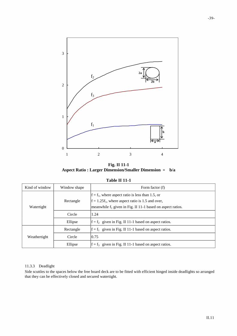
-39-
II.11
0
1
2
3
1 2 3 4
Fig. II 11-1
Aspect Ratio : Larger Dimension/Smaller Dimension ﹦ b/a
Table II 11-1
Kind of window Window shape Form factor (f)
Watertight
Rectangle
f = f1, where aspect ratio is less than 1.5, or
f = 1.25f1, where aspect ratio is 1.5 and over,
meanwhile f1 given in Fig. II 11-1 based on aspect ratios.
Circle 1.24
Ellipse f = f2 given in Fig. II 11-1 based on aspect ratios.
Rectangle f = f1 given in Fig. II 11-1 based on aspect ratios.
Weathertight Circle 0.75
Ellipse f = f3 given in Fig. II 11-1 based on aspect ratios.
11.3.3 Deadlight
Side scuttles to the spaces below the free board deck are to be fitted with efficient hinged inside deadlights so arranged
that they can be effectively closed and secured watertight.
f3
f2
f1
2b
2a
a
b

-40-
II.12
Chapter 12
Hatchway Openings, Machinery Openings
and Other Deck Openings
12.1 General
12.1.1 All openings on decks are to be reinforced as necessary to provide efficient support and attachment to the
ends of the deck structures.
12.1.2 For ships applying to the International Convention on Load Lines, the arrangements and constructions of deck
openings are to comply with the requirements of the conventions.
12.1.3 Where the ships engaged only in restricted area or domestic area comply with the relevant requirements of the
ship's Administration, the relevant requirements of the ship's Administration may be deemed as substitute for the
requirements specified in this chapter at the discretion of the Society.
12.2 Hatchway Openings
12.2.1 Height of Hatch Coamings
(a) The height of hatch coamings above the upper deck laminates is not to be less than the value specified as
follows:
(i) For L 24 m, non-fishing vessels
600 mm position 1; 450 mm position 2
(ii) For L 24 m, fishing vessel
600 mm position 1; 300 mm position 2
(iii) For L < 24 m, non-fishing vessels
450 mm position 1; 300 mm position2
(iv) For L < 24 m, fishing vessels
300 mm position 1; 300 mm position 2
where position 1 and position 2 as defined in International Convention on Load Lines.
(b) With respect to hatchway openings which are maintained weathertight by means of gaskets and clamping
devices and closed with substantial weathertight covers, the height of hatch coamings may be reduced from
the value required in the preceding (a) subject to the approval by the Society.
12.2.2 Hatch Covers
(a) Covers are to be constructed in accordance with the requirements given in Table II 12-1 & Table II 12-2.
(b) Materials for wooden covers are to be of good quality, straightgrained and reasonably free from knots,
sapwood and shakes.
(c) The ends of wooden covers are to be protected by circling steel bands.
(d) Hatch rests are to be provided with at least 65 mm bearing surface and are to be beveled, if required, to suit
the slope of the hatchways.

-41-
II.12
Table II 12-1
Thickness of Hatch Covers
Material Minimum Thickness Remark
Wood 32S h but not less than 48 mm
FRP 16S h -
Al Alloy 11S h -
Steel 5.5S h + 1.0 but not less than 4.5 mm
Where: S = Spacing of portable beam, in m (wood)
Spacing of stiffeners, in m (other material)
h = As given in 12.2.3, in m
Table II 12-2
Section Modulus of Stiffeners for Hatch Covers
Material Min. Section Modulus (cm3)
FRP 23.4 Shl2
Al Alloy 13.3 Shl2
Steel 9.4 Shl2
Where: S = Spacing of stiffeners, in m
h = As given in 12.2.3, in m
l = Span of supports, in m
12.2.3 Load Acting on Hatch Covers
For hatch covers, the load h is to be specified as follows:
(a) Position 1
h = 0.010L + 0.76 m
(b) Position 2
h = 0.008L + 0.58 m
(c) Cover intended to carrying cargo
h = Cargo load head, in m, or (a)/(b), whichever is greater.
12.2.4 Tarpaulins and Securing Arrangements for Hatchways closed by Portable Covers
(a) At least two layers of tarpaulin are to be provided for each exposed hatchway on the freeboard or
superstructure decks and at least one layer of such tarpaulin is to be provided for each exposed hatchway
elsewhere.
(b) Battens are to be efficient for securing the tarpaulins and not to be less than 65 mm in width and 9 mm in
thickness.
(c) Wedges are to be of tough wood or other equivalent materials. They are to have a taper of not more than 1
in 6 and not to be less than 13 mm in thickness at the point.
(d) Cleats are to be set to fit the taper of the wedges. They are to be at least 65 mm wide and to be spaced not
more than 600 mm from center to center; the cleats along each side or end are to be arranged not more than
150 mm apart from the hatch corners.
(e) For all hatchways in the exposed freeboard and superstructure decks, steel bands or other equivalent means
are to be provided in order to efficiently secure each section of hatchway covers after the tarpaulins are
battened down. Hatchway covers of more than 1.5 m in length are to be secured by at least two such
securing appliances. At all other hatchways in exposed positions on weather decks, ring bolts or other
fittings for lashing are to be provided.
-42-
II.12
12.3 Machinery Openings
12.3.1 Protection of Machinery Openings
Machinery openings are to be as small as possible, and to be enclosed by casings.
12.3.2 Casings of Machinery Openings in Exposed Parts
(a) Exposed machinery openings on the upper decks and superstructure decks are to be in accordance with the
requirements in the following:
(i) The thickness of casings and the section modulus of stiffeners thereupon, are to be equivalent to
those of boundary walls of superstructures specified in 11.2.1.
(ii) The thickness of top laminates of casings and the section modulus of stiffeners thereupon, are not to
be less than 4.0 mm and 24 cm3 respectively.
(b) The height of casings is, except special cases, not to be less than that of bulwark.
(c) Where access openings are provided on the exposed machinery casings, these openings are to be located in
protected spaces as far as practicable, the doors thereof are to be in accordance with the requirements
11.2.3(a) and the height of sills above the upper surface above of deck laminates is to be in accordance with
the requirements in 11.2.3(b).
12.3.3 Position of Fittings
Skylights provided on the top laminates of machinery casings are to be of substantial construction and coamings of
funnels and ventilators are to be provided as high as possible above the weather deck laminates.
12.4 Other Openings
12.4.1 Manholes and Flush Deck Openings
Manholes and flush deck openings which are provided in exposed parts of freeboard deck and superstructure decks or
in the superstructures other than those enclosed, are to be closed with substantial covers capable of keeping
watertightness.
12.4.2 Companionways
(a) Companionways on the freeboard deck are to be protected by enclosed superstructures or by deckhouses or
companions which have strength and weathertightness equivalent to those of enclosed superstructures.
(b) Companionways on exposed superstructure decks and those on the top of deckhouses which give access to
spaces below the freeboard deck or spaces within enclosed superstructures, are to be protected by effective
deckhouses or companions.
(c) Access openings in the deckhouses or companions specified in the preceding (a) and (b) are to be provided
with doors in accordance with the requirements in 11.2.3(a). And, the height of sills of the access openings
above the surface of deck laminates is to be in accordance with the requirements in 11.2.3(b).
12.4.3 Openings to Cargo Spaces
All of access and other openings to cargo spaces are to be provided with weathertight closing means capable of being
operated from outside the spaces in case of fire.
RULES AND REGULATIONS FOR THE
CONSTRUCTION AND CLASSIFICATION OF
SHIPS OF FIBREGLASS REINFORCED
PLASTICS 2017
PART III – EQUIPMENT AND FITTINGS
April 2017
RULES AND REGULATIONS FOR THE
CONSTRUCTION AND CLASSIFICATION OF SHIPS
OF FIBREGLASS REINFORCED PLASTICS
PART I GENERAL REQUIREMENTS 2017
PART II HULL CONSTRUCTION 2017
PART III EQUIPMENT AND FITTINGS 2017
PART IV MACHINERY INSTALLATIONS 2017
PART V ELECTRICAL INSTALLATION 2017

List of major changes in Part III from 1998 edition
1.2.1(d) Amend No.1
1.2.3(a) Amend No.1
1.2.4(c) Amend No.1
Chapter 3 Amend No.1

RULES AND REGULATIONS FOR
THE CONSTRUCTION AND CLASSIFICATION OF SHIPS OF
FIBREGLASS REINFORCED PLASTICS
2017
PART III
EQUIPMENT AND FITTINGS
CONTENTS
Chapter 1 Bulwarks, Guardrails, Freeing Arrangements, and Gangways .............................................. 1
1.1 Bulwarks and Guardrails ............................................................................................................................. 1 1.2 Freeing Arrangements ................................................................................................................................. 1 1.3 Ventilators ................................................................................................................................................... 3 1.4 Gangways ................................................................................................................................................... 4 1.5 Vessels not Applying to Load Line Conventions ........................................................................................ 4
Chapter 2 Rudders and Shaft Struts ........................................................................................................... 5
2.1 Rudders ....................................................................................................................................................... 5 2.2 Shaft Struts ................................................................................................................................................ 10
Chapter 3 Equipment .................................................................................................................................. 12
3.1 General ...................................................................................................................................................... 12
Chapter 4 Fire Fighting Equipment and Arrangements .......................................................................... 13
4.1 General ...................................................................................................................................................... 13 4.2 Equipment and Arrangements ................................................................................................................... 13


-1-
III.1
Chapter 1
Bulwarks, Guardrails, Freeing Arrangements,
and Gangways
1.1 Bulwarks and Guardrails
1.1.1 General
Efficient guardrails or bulwarks are to be provided on all exposed parts of the freeboard and superstructure decks or
the top of similar deckhouses.
1.1.2 Dimensions
(a) The height of bulwarks or guardrails specified in 1.1.1 is to be at least one meter from the upper surface of
deck, provided that where this height would interfere with the normal operation of the ship, a less height
may be permitted where adequate protection is provided.
(b) The clearance below the lowest course of guardrails in (a) is not to exceed 230 mm. The clearance between
other courses is not to exceed 380 mm.
1.1.3 Construction
(a) Bulwarks are to be strongly constructed according to their height and effectively stiffened on their upper
edges. The laminated thickness of bulwarks on the freeboard deck is generally to be at least 80% of the side
shell laminate.
(b) Bulwarks are to be supported by stays connected to the deck in way of the beams or at effectively sti ffened
positions. The spacing of these stays on the freeboard deck is not to be more than 1.8 meters.
1.1.4 Miscellaneous
(a) Gangways and other openings in bulwarks are to be keep well clear of the ends of superstructures.
(b) Where bulwarks are cut to form gangways or other openings, stays of increased strength are to be provided
at the ends of the openings.
(c) The plating of bulwarks in way of mooring pipes is to be increased in lamination.
(d) At ends of superstructures, the bulwark rails are to be bracketed either to the superstructure end bulkheads
or to the stringer plates of the superstructure decks, or other equivalent arrangements are to be made so that
the abrupt change in strength can be avoided.
1.2 Freeing Arrangements
1.2.1 General
(a) Where bulwarks on the weather parts of freeboard or superstructure deck form wells, ample provision is to
Chapter 2 Materials be made for rapidly freeing the water of decks, and for draining them.

-2-
III.1
(b) Ample freeing ports are to be provided for draining water from any space other than wells, where lots of
water is liable to remain.
(c) In ships having superstructures which are open at either or both ends, adequate provision for freeing the
space within such superstructures is to be provided.
(d) In ships having a reduced freeboard, guardrails are to be provided for at least a half of the length of the
exposed parts of the weather deck or other effective freeing arrangements are to be considered, as required
by the Society.
1.2.2 Freeing Port Area
(a) The area of the freeing port specified in 1.2.1(a) on each side of the ship for each well on the freeboard
deck is not to be less than the value obtained by the following formulae. The area for each well on
superstructure decks is not to be less than one-half of that obtained by the formulae:
(i) Where is not more than 20 meters:
A = 0.7 + 0.035l + a m2
(ii) Where l is more than 20 meters:
A = 0.07 l + a m2
where
l = length of bulwark in way of the well,in m, but if the length is 0.7L or more, it is taken as 0.7L
a = as obtained by the following formulae:
(1) where h is more than 1.2 meters:
0.04 l (h - 1.2) m2
(2) where h is not more than 1.2 meters, but not less than 0.9 meters:
0 m2
(3) where h is less than 0.9 meters:
-0.04 l (0.9 - h) m2
h = average height of bulwarks above the deck, in m
(b) In ships either without sheer or with less sheer than the standard, the minimum freeing port area obtained
by the formula in (a) is to be increased by multiplying the factor obtained from the following fo rmula:
= 1.5 S
2S0
where
S = average of actual sheer, in mm
S0 = average of the standard sheer given by the International Convention on Load Lines, 1966 , in mm

-3-
III.1
(c) Where a ship is provided with a trunk or a hatch side coaming which is continuous or substantially
continuous between detached superstructures, the area of freeing port is not to be less than the value given
in Table III 1-1.
Table III 1-1
Area of Freeing Ports
Breadth of hatchway or
trunk (m)
Area of freeing ports in
relation to the total area of
bulwark
0.4B or less
0.75B or more
0.2
0.1
Note: The area of freeing ports where the breadth of trunk or hatchway assumes an intermediate value given in the
table is to be obtained by linear interpolation.
(d) Notwithstanding the requirements in preceding (a) to (c), in ships having trunks on the freeboard deck,
guardrails are to be provided for more than half of the length of trunk instead of bulwarks on both sides of
the freeboard deck in way of trunks.
1.2.3 Arrangement of Freeing Ports
(a) Two-thirds of the freeing port area required by 1.2.2 is to be provided for the half of the well near the
lowest point of the sheer curve, and the remaining one-third is to be evenly spread along the remaining
length of the wall.
(b) The freeing ports are to have well rounded corners and their lower edges are to be as near the deck as
practicable.
1.2.4 Construction of Freeing Ports
(a) Where both the length and the height of freeing ports exceed 230 mm respectively, freeing ports are to be
protected by rails spaced approximately 230 mm apart.
(b) Where shutters are provided on freeing ports, ample clearance is to be provided to prevent jamming. Hinge
pins or bearings of the shutters are to be of non-corrodible materials.
(c) Where the shutters referred to in preceding (b) are not to be provided with securing appliances.
1.3 Ventilators
1.3.1 Height of Ventilator Coamings
The height of ventilator coamings above the upper surface of the deck is to be at least 900 mm in Position I and 760
mm in Position II. However, where the ship has an unusually large freeboard or where the ventilator serves spaces
within unenclosed superstructures, the height of ventilator coamings may be suitably reduced.
1.3.2 Thickness of Ventilator Coamings
(a) The thickness of ventilator coamings in Positions 1 and 2 leading to spaces below the freeboard deck or
within enclosed superstructures is not to be less than the value given by Line 1 in Table III 1 -2. Where the
height of coamings is reduced by the provisions in 1.3.1, the thickness may be suitably modified.
(b) Where ventilators pass through superstructures other than enclosed superstructures, the thickness of
ventilator coamings in the superstructures is not to be less than the value given by Line 2 in Table III 1-2.

-4-
III.1
Table III 1-2
Thickness of Ventilator Coamings
Inside diameter of ventilator d
(mm)
d < 70 70 d < 100 100 d < 130 130 d < 160 160 d < 190 190 d
Thickness of coaming - FRP
laminate plate (mm)
Line 1 12.2 13.7 15.4 15.4 15.4 15.4
Line 2 8.7 8.7 8.7 8.7 10.4 12.2
1.3.3 Connection
Ventilator coamings are to be efficiently connected to the deck and, where their height exceeds 900 mm, are to be
specially supported.
1.3.4 Cowls
Ventilator cowls are to be fitted up closely to the coamings and are to have housing not less than 380 mm, except that
a less housing may be permitted for ventilators not greater than 200 mm in diameter.
1.3.5 Closing Appliances
(a) Ventilators for machinery and cargo spaces are to be provided with means for closing means capable of
being operated from outside the spaces in case of a fire.
(b) All ventilator openings in exposed positions on the freeboard and superstructure decks are to be provided
with efficient weathertight closing appliances. However, where the height of their coaming exceeds 4.5 m
above the freeboard and above the superstructure deck for 0.25L forward or 2.3 m above the other
superstructure decks, such closing appliances may be omitted except those required in preceding (a).
1.3.6 Ventilators for Deckhouses
The ventilators for the deckhouses which protect the companionways leading to the spaces below the freeboard deck
are to be equivalent to those for the enclosed superstructures.
1.4 Gangways
1.4.1 General
Satisfactory means e.g., guardrails, life lines, gangways or under deck passages are to be provided for the protection of
the crew in getting to and from their quarters, the machinery space and all other parts used in the necessary work of the
ship.
1.4.2 Construction of Gangways
The permanent gangways are to be, in general, at least 600 mm wide and to be provided with guardrails which are at
least one meter high complying with the requirements in 1.1.2(b) on their both sides.
1.5 Vessels not Applying to Load Line Conventions
For ships not applying to load line convention, the requirements of bulwarks, guardrails, freeing arrangements,
ventilators and gangways specified in 1.1 to 1.4 are to be in accordance with the discretion of the Society.
-5-
III.2
Chapter 2
Rudders and Shaft Struts
2.1 Rudders
2.1.1 Applications
The following requirements generally apply to the rudder constructed as a double-plated stream line section of
ordinary shape and single plate, as well as not more than two pintles, designed with a moving angle not more than 350
on each side without any special arrangement for increasing the rudder force, such as fins, flaps steering propellers, etc.
Rudders not confirming with the ordinary types are to be approved under special consideration by the Society.
2.1.2 Materials
(a) Rudder stocks, pintles, flanges, coupling bolts, keys and cast parts of rudder are to made of rolled, forged
steel or cast carbon manganese steel confirming to the requirements of Part XI of the Steel Ship Rules.
(b) Welded part of rudders are to be made of approval rolled hull materials.
(c) Required scantlings may be reduced with consideration of the material factor K as specified in 1.5.2(c) of
Part II of the Steel Ship Rules when higher tensile material are used.
(d) Before significant reductions in rudder stock diameter due to the application of higher tensile steels are
granted, the evaluation of the large rudder stock deformations is to be submitted for consideration in order
to avoid excessive edge pressure in way of bearings.
2.1.3 Arrangements
(a) Effective means are to be provided for preventing the rudder from jumping and for supporting the weight
of the rudder without excessive bearing pressure. They are to be arranged to prevent accidental unshipping
or undue movement of the rudder which may cause damage to the steering gear.
(b) A sealing devices or stuffing box is to be fitted to prevent water from entering the steering gear spaces and
the lubricant from being washed away the rudder carrier.
2.1.4 Rudder force
The rudder force upon which the rudder scantlings are to be based is to be determined from the following formula:
F = 145K1K2AV2
where:
F = Rudder force, in N
A = Area of rudder blade, in m2
V = Maximum service speed of ship, in knots, with the ship on designed load line, when the service speed
10 knots
=
1
3 (V + 20), where the service speed < 10 knots
K1 = Factor depending on the aspect ratio of the rudder area

-6-
III.2
=
1
3( + 2)
= h2
At
2
h = mean height of ruder area, in m, as shown in Fig. III 2-1
At = Sum of rudder blade area A and area of rudder post or rudder horn, if any, within the mean height h, in m2
K2 = 0.8 for rudders out side the propeller jet
= 1.15 for rudder behind a fixed propeller nozzle
= 1.0 otherwise
2.1.5 Rudder Torque
The rudder torque is to be calculated for both the ahead and astern condition from the following formula:
Q = Fr Nm
where:
Q = Rudder torque, in Nm
r = b(0.33-k), in m
0.1b
b = Mean breadth of rudder area, in m, see Fig. III 2-1
k = Balance factor
=
A
A
A = Portion of the rudder blade area situated ahead of the center line of the rudder stock
A = Area of rudder blade, in m2
2.1.6 Rudder strength calculation
(a) The rudder strength is to be sufficient against the rudder force and rudder torque as given in 2.1.4 and
2.1.5. When the scantling of each part of a rudder is determined the following moments and forces are to be
considered:
(i) For rudder body:
bending moments and shear forces
(ii) For rudder stock:
bending moments and torque
(iii) For pintle bearing and rudder stock bearing:
supporting force
(b) The bending moments, shear forces and supporting forces to be considered are to be determined by a direct
calculation or by an approximate simplified method as deemed appropriate by the Society.
2.1.7 Rudder Stock
(a) The rudder stock diameter for the transmission of the rudder torque is not to be less than the value obtained
from the following formula:
du = 4.2 3 QK mm

-7-
III.2
where:
du = Diameter of upper rudder stock in way of the tiller.
K = Defined in 2.1.2(c)
(b) The diameter of the lower stock subjected to combined forces of torque and bending moment is to be
determined such that the equivalent stress in the rudder stock does not exceed 118
K (N/mm
2)
The equivalent stress is to be determined by the formula:
2t
2bc 3 N/mm2
Bending stress 3bd
M2.10
l
N/mm2
Torsional stress 3td
Q1.5
l
N/mm2
where:
M = Bending moment, in Nm, at the section of the rudder stock considered.
Q = As specified in 2.1.5 above.
dl = Lower stock diameter, in mm
Therefor, the lower stock diameter is not to be less than that obtained from the following formula:
6
2
uQ
M
3
41dd
l
mm
where:
du = Upper rudder stock diameter, in mm, as given in (a) above
2.1.8 Rudder Plates, Rudder Webs and Rudder Main Pieces
(a) The thickness of the rudder side, top and bottom plating made of ordinary hull structural steel is not to be
less than the value obtained from the following formula:
5.2A
10Fds5.5t
4
f
mm
where:
d= Designed load line draught of the ship (m)
F = Rudder force (N)
A = Rudder area (m2)
= 2
b
s5.01.1
Max. 1.00 for
s
b 2.5
s = Smallest unsupported width of plating, in m
b = Greatest unsupported width of plating, in m
-8-
III.2
(b) The plating is to be suitably stiffened by vertical and horizontal webs. The thickness of web plates is not to
be less than 70% of the rudder side plating, however, not less than 8 mm. For higher tensile steels the
material factor according to 2.1.2(c) is to be adopted.
(c) Mainpiece.
(i) The thickness of the plating of the rudder with plate frames may require to be increased in way of
vertical webs which replace the mainpiece.
(ii) Horizontal webs and vertical webs not replacing the mainpiece are to have the same thickness as the
rudder plating, but plates forming the top and the bottom of the rudder are to be of increased
thickness.
(iii) Vertical webs replacing the mainpiece may be required to be increased in thickness.
(iv) The spacing of vertical webs are generally not to be larger than 1.5 times the horizontal web
spacing.
2.1.9 Single plate rudder.
(a) The mainpiece diameter is to be calculated according to 2.1.8. For spade rudders the lower third may taper
down to 0.75 times stock diameter.
(b) The blade thickness, tb, is not to be less than the value obtained from the following formula:
tb = 1.5 s V + 2.5 mm
where:
s = Spacing of stiffening arms, in m, not to exceed 1 m.
V = Speed, in knots, as specified in 2.1.4
(c) The thickness of the arms, ta , is not to be less than the blade thickness, tb:
ta tb
(d) The section modulus, Z, is not to be less than the value obtained from the following formula:
Z = 0.5 s x2 V2 cm3
where:
s = Spacing of stiffening arms, in m, not to exceed 1 m
V = Speed, in knots, as specified in 2.1.4
x = Horizontal distance from the aft edge of the rudder to the centerline of the rudder stock, in m
(e) For higher tensile steels the material factor is to be adopted according to 2.1.2(c).
2.1.10 Horizontal rudder stock couplings.
(a) Coupling bolts are to be reamer bolts. The diameter of the coupling bolts is not to be less than the value
obtained from the following formula:

-9-
III.2
s
b3
bneK
Kd62.0d mm
where:
d = Stock diameter, in mm, the greater of the du or d as specified in 2.1.7
n = Total number of bolts
6
e = Mean distance of the bolt axis from the center of the bolt system
Kb = Material factor for the bolt as specified in 2.1.2 (c)
Ks = Material factor for the stock as specified in 2.1.2 (c)
(b) The thickness of the coupling flanges is not to be less than the value obtained from the following formula:
b
fbf
K
Kdt mm
where:
tf = Thickness of coupling flanges, in mm
0.9 db
db = Bolt diameter (mm) for a number of bolts not exceeding 8
Kb = Material factor for the bolt as specified in 2.1.2 (c)
Kf = Material factor for the flange as specified in 2.1.2 (c)
(c) The width of material outside the bolt holes is not to be less than 0.67 db.
2.1.11 Pintles
(a) Pintles are to have a conical attachment to the gudgeon with a taper on diameter of:
(i) 1:8 to 1:12
for keyed and other manually assembled pintles applying locking by slugging nut.
(ii) 1:12 to 1:20
for pintles mounted with oil injection and hydraulic nut.
(b) The length of the pintle housing in the gudgeon is not to be less than the minimum pintle diameter:
pbp KF35.0d mm
where:
Fb = The relevant bearing force, in N
= 0.5 F for bottom pintles
F = Rudder force (N) as specified in 2.1.4(a)
Kp = Material factor for the pintle as specified in 2.1.2(c)
2.1.12 Rudder Stock Bearings and Pintle Bearings

-10-
III.2
(a) The bearing surface, Ab, defined as the projected area: length x outside diameter of sleeve, is not to be less
than the value obtained from the following formula:
a
bb
q
FA mm2
where:
Fb = Reaction force, in N, as specified in 2.1.11
qa = Allowable surface pressure as listed in Table III 2-1.
(b) An adequate lubrication is to be ensured.
(c) The length/diameter ratio of the bearing surface is not to be greater than 1.2.
(d) Metal bearings clearances are not to be less than db
1000 + 1.0 mm on the diameter. Where db: Inter diameter
of bush, in mm. If nonmetallic bearing material is applied, the bearing clearance is to be specially
determined considering the materials swelling and thermal expansion properties. This clearance in no way
is to be taken less than 1.5 mm on bearing diameter.
Table III 2-1
Allowable Surface Pressure, qa
Bearing material qa (N/mm2)
Lignum-vitae 2.5
White metal, oil lubricated 4.5
Synthetic material with hardness between 60 and 70 Shore D (Note 1) 5.5
Steel (Note 2) and bronze and hot-pressed bronze- graphite materials 7.0
Notes:
1. Indentation hardness test at 23C and 50% moisture, according to a recognized standard. Synthetic bearing
materials to be of approved type.
2. Stainless and wear-resistant steel in an approved combination with stock liner. Higher values than given in the
Table may be taken if they are verified by tests.
2.2 Shaft Struts
2.2.1 General
Shaft struts may be of V or I type. The thickness of the strut barrel or boss is to be at least one-fifth the required
diameter of the tail shaft. Special consideration will be given to the use of materials other than steel or aluminum. The
following equations are for struts having streamline cross-sectional shapes. Other methods of determining scantlings
may be considered.
2.2.2 Width and Thickness
The thickness and width of each strut area is to be not less than those obtained from the following formulae:
(a) V strut
t = 0.365d w = 2.27d
(b) I strut

-11-
III.2
t = 0.515d w = 3.22d
where
t = thickness of strut (minor axis)
w = width of strut (major axis)
d = required diameter of forging steel tail shaft, in mm
Where the included angle of V strut is less than 45°, the sizes in above may be specially considered.
2.2.3 Strut Length
The length of the longer leg of a V strut or the leg of an I strut, measured from the outside of the strut barrel or boss to
the outside of the shell plating, is not to exceed 10.6 times the required diameter of the tail shaft. Where this length is
exceeded, the width and thickness of the strut are to be increased, and the strut design may be given a special
consideration.
b = 1
2 (X2 + X3 - X1)
h = 1
2 (Z3 + Z4 - Z2)
X1
2
A
3
4
b
h
Z
Fig. III 2-1
Rudder Blade without Cutout

-12-
III.3
Chapter 3
Equipment
3.1 General
3.1.1 If a ship is provided with a complete equipment of the anchor, the chain and the mooring rope in accordance
with the requirements specified in chapter 25 Part II of the Steel Ship Rules, the letter E will be placed after the
symbol of classification of Hull.
3.1.2 In the case of ships classed for a special or restricted service, if approved by the Society that requirements of
the Rules are not necessary to apply, no equipment symbol is to be affixed.
3.1.3 The number and mass of anchors and the length and the size of the chain, and the mooring rope for a classed
ship are to be determined from Table II 25-1 of Part II of the Steel Ship Rules.
3.1.4 If an ordinary stocked or stockless type of anchor was adopted, the relevant requirements specified in chapter
25 of Part II of the Steel Ship Rules are to be complied with.
3.1.5 The equipment for fishing ships may be based on the "Equipment Number" which is less than 10% the value
determined as mentioned above.
3.1.6 For ships to be classed for Protected Waters Service, equipment numeral in Table II 25-1 of Part II of the
Steel Ship Rules may be degraded one rank.
3.1.7 For ships to be classed for Coastal Service, the mass of one of the two anchors may be reduced 15% of the
mass required in Table II 25-1 of Part II of the Steel Ship Rules.

-13-
III.4
Chapter 4
Fire Fighting Equipment and Arrangements
4.1 General
4.1.1 In addition to comply with the requirements of the Administration of the ship, the requirements specified in
this chapter are also to be complied with.
4.1.2 Fire protection appliances are to be kept in good order and available for immediate use at all times.
4.2 Equipment and Arrangements
4.2.1 Ships of 12 meters or more in length are to be provided with the following fire-fighting equipment. However,
the requirements in (a) through (e) do not apply to ships with a gross tonnage of less than 300 tons.
(a) One fire pump driven by independent power.
(b) One emergency hand fire pump provided outside the machinery space.
(c) Fire hydrants to be so arranged that one jet of water by a single fire hose is available (cargo spaces assumed
to be in empty condition) to reach any part of the ship normally accessible to the passengers or crew while
the ship is being navigated.
(d) Three fire hoses.
(e) Three nozzles (spray/jet) with valves.
(f) Portable fire extinguishers;
(i) One portable foam fire extinguisher or portable chemical powder fire extinguisher per every 750
kW of output in space where internal combustion engine is installed (minimum two, maximum six
in number).
(ii) Three portable fire extinguishers in accommodation space and service space (to be distributed to
each space as appropriate).
4.2.2 Ships of less than 12 meters in length are to be provided with the following fire-fighting equipment:
(a) Ships equipped with inboard engine or in/outboard engine are to be provided with three portable liquid fire
extinguishers or portable chemical powder fire extinguishers.
(b) For ships equipped with outboard engine only, the quantities of portable fire extinguishers may be reduced
by one from the quantities specified in (a) above.
4.2.3 Fixed Fire Fighting System
For passenger ships, a fixed fire fighting system with a capacity sufficient for the volume of machinery space where
normally unattended by crewmembers is to be provided and remotely controlled from the operation compartment.


RULES AND REGULATIONS FOR THE
CONSTRUCTION AND CLASSIFICATION OF
SHIPS OF FIBREGLASS REINFORCED
PLASTICS 2017
PART IV – MACHINERY INSTALLATIONS
April 2017

RULES AND REGULATIONS FOR THE
CONSTRUCTION AND CLASSIFICATION OF SHIPS
OF FIBREGLASS REINFORCED PLASTICS
PART I GENERAL REQUIREMENTS 2017
PART II HULL CONSTRUCTION 2017
PART III EQUIPMENT AND FITTINGS 2017
PART IV MACHINERY INSTALLATIONS 2017
PART V ELECTRICAL INSTALLATION 2017

List of major changes in Part IV from 1998 edition
Nil.

RULES AND REGULATIONS FOR
THE CONSTRUCTION AND CLASSIFICATION OF SHIPS OF
FIBREGLASS REINFORCED PLASTICS
2017
PART IV
MACHINERY INSTALLATIONS
CONTENTS
Chapter 1 General ......................................................................................................................................... 1
1.1 General ........................................................................................................................................................ 1 1.2 Drawings and Data ...................................................................................................................................... 1 1.3 Materials ..................................................................................................................................................... 1 1.4 General Construction .................................................................................................................................. 2 1.5 Tests and Inspections .................................................................................................................................. 3
Chapter 2 Diesel Engines .............................................................................................................................. 5
2.1 General ........................................................................................................................................................ 5 2.2 Drawings and Data ...................................................................................................................................... 5 2.3 Materials ..................................................................................................................................................... 5 2.4 Construction ................................................................................................................................................ 5 2.5 Starting Arrangements ................................................................................................................................ 6 2.6 Air Intake and Exhaust Arrangements ........................................................................................................ 7 2.7 Fuel, Lubrication and Cooling Arrangements ............................................................................................. 7 2.8 Tests and Inspections .................................................................................................................................. 8
Chapter 3 Deck Machinery and Essential Auxiliaries ................................................................................ 9
3.1 General ........................................................................................................................................................ 9 3.2 Drawings and Data ...................................................................................................................................... 9 3.3 Materials ..................................................................................................................................................... 9 3.4 Steering Gear .............................................................................................................................................. 9 3.5 Windlass ...................................................................................................................................................... 9 3.6 Reciprocating Compressor ........................................................................................................................ 10 3.7 Pumps ....................................................................................................................................................... 10 3.8 Tests and Inspections ................................................................................................................................ 10
Chapter 4 Gearing and Couplings .............................................................................................................. 11
4.1 General ...................................................................................................................................................... 11
Chapter 5 Shaftings, Propellers, Waterjet Propulsion System and Torsional Vibration of Shafting .. 12
5.1 Shaftings ................................................................................................................................................... 12 5.2 Propellers .................................................................................................................................................. 13

5.3 Waterjet Propulsion Systems .................................................................................................................... 15 5.4 Torsional Vibration of Shafting ................................................................................................................. 16 5.5 Tests and Inspections ................................................................................................................................ 16
Chapter 6 Piping and Pumping System ..................................................................................................... 17
6.1 General ...................................................................................................................................................... 17 6.2 Ship's Side Fittings.................................................................................................................................... 17 6.3 Air Pipes and Overflow Pipes ................................................................................................................... 17 6.4 Sounding Pipes ......................................................................................................................................... 18 6.5 Hull Piping System ................................................................................................................................... 18 6.6 Drainage of Cargo Holds .......................................................................................................................... 18 6.7 Drainage of Machinery and Tunnel Spaces .............................................................................................. 18 6.8 Drainage from Refrigerated Cargo Holds ................................................................................................. 18 6.9 Drainage from Spaces in Other Decks ...................................................................................................... 18 6.10 Drainage of Tanks ..................................................................................................................................... 18 6.11 Sizes of Bilge Suction Pipes ..................................................................................................................... 18 6.12 Bilge Pumps .............................................................................................................................................. 19 6.13 Ballast System........................................................................................................................................... 19 6.14 Cooling Water System .............................................................................................................................. 20 6.15 Fuel Oil System ........................................................................................................................................ 20 6.16 Lubricating Oil and Hydraulic system ...................................................................................................... 21 6.17 Starting Air System ................................................................................................................................... 21 6.18 Exhaust Gas Piping Arrangement for Diesel Engine ................................................................................ 21 6.19 Tests and Inspections ................................................................................................................................ 21
Chapter 7 Spare Parts for Machinery ....................................................................................................... 22
7.1 Scope......................................................................................................................................................... 22 7.2 General ...................................................................................................................................................... 22

-1-
IV.1
Chapter 1
General
1.1 General
1.1.1 Scope.
(a) The requirement of this Part apply to the main propulsion machinery, deck machinery and power
transmission system, shafting systems, propellers, waterjet propulsion systems, prime movers other than
main propulsion machinery and piping system.
(b) Machinery installations which are unusual and considered impracticable to meet the requirements of this
Part may be accepted provided they are deemed by the Society to be equivalent to those specified in this
Part.
(c) The Society will be prepared give special consideration to the novel features of design in respect of the
machinery based on the best information available at the time.
(d) Passenger Ships or with special service limitations or restrictions Ships intended for classification are to be
constructioned in accordance with the requirements of the Society as well as Governmental Regulations .
1.1.2 Units and formulae.
(a) Unit and formulae including in the Rules are shown in SI units.
(b) Pressure gauges may be calibrated in bar.
where: 1 bar = 0.1 MPa
1.1.3 Ambient reference conditions.
Ambient reference conditions are to be in accordance with the requirements specified in 1.2.3, PartⅣ of the Rules for
the Construction and Classification of Steel Ships.
1.1.4 Power rating.
Power rafting is to be in accordance with the requirements specified in 1.2.4, PartⅣ of the Rules for the Construction
and Classification of Steel Ships.
1.2 Drawings and Data
1.2.1 For machineries built under special survey during construction, drawings showing the proposed arrangements
of machinery compartments and such drawings of the machineries as stated in the subsequent Chapters of this Part are
to be submitted for approval before proceeding with the work.
1.2.2 The proposed dimensions and quality of materials as well as all important arrangements and details are to be
made clear in the drawings.
1.2.3 For any novel design of machinery, detailed drawings of parts and necessary data are to be submitted for
consideration.
1.3 Materials
1.3.1 Material intended to be used for machinery installations are to be selected considering the purpose and
condition of their service. Materials intended for principal components are to be of those tested and inspected in
accordance with the requirements specified in this Part and Part XI of the Rules for the construction and Classification
of Steel Ships.
-2-
IV.1
1.3.2 Materials used for machinery installations which are not specified in 1.3.1 of this Chapter are to be submitted
for consideration.
1.4 General Construction
1.4.1 General
(a) The machinery installations are to be properly fixed and to be of construction and arrangement to facilitate
operation, inspection and maintenance.
(b) The machinery installations are to be of a design and construction adequate for the service for which they
are intended and are to be so installed and protected as to reduce to a minimum any danger to persons on
board, due regard being paid to moving parts, hot surface and other hazards.
(c) Machinery installations are to be fitted with adequate safety monitoring and control devices in respect of
speed, temperature, pressure and other operation functions.
(d) Special consideration is to be given to the design, construction and installation of the machinery
installations so that any mode of vibrations, accelerations, shocks, etc., shall not cause undue stresses in
normal operating ranges.
1.4.2 Inclination of ships.
The designs and constructions of machinery installations are to be in compliance with accepted marine engineering
practices and the machineries are to be operable with complete reliability in all positions and motions with the ship
under the conditions as shown in Table IV 1-1, Part 1V of the Rules for the construction and classification of Steel
Ships.
1.4.3 Astern power.
(a) Sufficient power for going astern is to be provided to secure proper control of the ship in al l normal
circumstances.
(b) For the main propulsion system with reversing gear, controllable pitch propellers, waterjet propulsion
systems, or electric propulsion systems, running astern is not to lead to the overload of propulsion
machinery.
1.4.4 Welded construction.
The welded construction are to be in compliance with the requirements specified in Part XII of the Rules for the
Construction and Classification of Steel Ships.
1.4.5 Safety devices on moving parts
(a) Efficient means are to be provided to prevent the loosening of nuts and screws of moving parts.
(b) The moving parts of machinery and shafting are to be efficiently protected by means of handrails, screens,
etc.
1.4.6 Installation of machinery.
(a) Propulsion machinery, except for those of small output, are to be installed on the bottom girders through
the steel engine seatings of sufficient strength and rigidity.
(b) Where machinery having large unbalanced inertia force or large unbalanced moment of inertia or subjected
to large exciting force due to piston side thrust are installed, it is recommended that the steel engine
seatings are of sufficient length for the engines and the steel engine seatings on both sides are connected
each other or the steel engine seatings are of solid construction.

-3-
IV.1
(c) Where the temperature of the bedplates for propulsion machinery or engine seatings in contact with the
FRP girders may become the value to give bad influence on the creeping property of FRP in a normal
operating condition, an effective insulation is to be provided between the bedplates or seatings and FRP
girders.
(d) Considerations are to be given to installation of all machinery onto the FRP girders so that an excessive
creep deformation does not occur due to the weights and clamping forces of bolts.
(e) The accessories of machinery as well as spare parts of large dimensions are to be strongly secured so that
they can not move or become loose under the movements of the ship.
1.4.7 Ventilating systems for machinery spaces.
Machinery spaces are to be adequately ventilated so as to ensure that when machinery therein are operating at full
power in all weather conditions, an adequate supply of air is maintained to the spaces for the safety and comfort of
personnel, for the operation of the machinery and for the prevention of accumulation of flammable gases.
1.4.8 Dead ship start.
Means are to be provided so that the machinery can be brought into operation from a dead ship condition (e.g. a
condition under which the main propulsion machinery, and auxiliaries are not in operation due to an absence of power
and normal starting energy sources are depleted).
1.4.9 Protection against noise.
Measures are to be taken to reduce machinery noise in machinery spaces to acceptable levels as determined by the
National Regulations of the country in which the ship is registered. If this noise cannot be sufficiently reduced the
source of excessive noise is to be suitably insulated or isolated or a refuge from noise is to be provided if the space is
required to be manned. Ear protectors are to be provided for personnel required to enter such spaces , if necessary.
1.4.10 Limitation in the use of fuel oil.
Except for cases as specified in (a) to (c) below, no fuel oil with a flash point (to be determined by means of
closed-cup test) of less than 60°C is to be used.
(a) In emergency generators, fuel oil with a flash point of not less than 43°C may be used.
(b) Subject to such additional precautions as it may consider necessary and on condition that the ambient
temperature of space in which such fuel oil is stored or used shall not be allowed to rise to within 10°C
below the flashpoint of the fuel oil, the general use of fuel oil having a flashpoint of less than 60°C but not
less than 43°C may be permitted.
(c) The use of fuel oil having a flashpoint of less than 43°C may be permitted provided that such fuel oil is not
stored in any machinery space and subject to the approval by this Society .
1.4.11 Automatic trips.
A description of all automatic trips that may affect the vessels propulsion system is to be submitted for review.
1.4.12 Boilers, pressure vessels and turbines.
When fitted , boilers and pressure vessels are to be designed and constructed in accordance with Part V of the Rules
for the Construction and Classification of Steel Ships , turbines are to comply with Part IV of the Rules for the
Construction and Classification of Steel Ships.
1.5 Tests and Inspections
1.5.1 Shop tests and inspections.
The machinery for ships classed or intended to be classed, built under the special survey during construction, is
normally to be tested and inspected in the presence of the surveyor in accordance with the requirement of Rules and
the approved drawings:
(a) Approval of proper material used and their material tests for component parts of machinery set out in the
relevant Chapters of this Part.
-4-
IV.1
(b) Workmanship for machining from the commencement of work until the finish inspections for component
parts of machinery.
(c) Tightness, balancing and non-destructive tests etc. for component parts of machinery set out in the relevant
Chapters of this Part.
(d) Trial testing of machinery.
1.5.2 Tests and inspections after installation on board.
After installation on board, the following tests and inspections are to be carried out:
(a) Verification inspection of installation or fixing condition of machinery.
(b) On-board tests and inspection of machinery and essential systems are to be carried out in accordance with
the requirements of the relevant Chapters of this Part.
(c) Other test and inspections not included in this Part may be required if deemed necessary by the society.
1.5.3 The society will be prepared on application to adopt the alternative methods of inspection for the production
line machinery and component parts subject to approval of manufacturer's production procedure and quality control.
1.5.4 Where the machinery or component part of machinery have appropriate certificates, the tests and inspections
may be wholly or partially dispensed with subject to further considerations and special approval by the Society.

-5-
IV.2
Chapter 2
Diesel Engines
2.1 General
2.1.1 The construction and installation of diesel engines for main propelling and essential service are to be carried
out in accordance with the following requirements under the supervision and to the satisfaction of the surveyor.
2.1.2 Diesel engines which drive electric propulsion generators are to be constructed and installed in accordance
with the following requirements as well as the requirements stated in 3.2 of Part VII of the Rules for the Construction
and Classification of Steel Ships.
2.2 Drawings and Data
Drawings and data to be submitted for approval are generally to comply with the requirements specified in 3.2, part IV
of the Rules for the Construction and Classification of Steel Ships.
2.3 Materials
2.3.1 Materials intended for the component parts of diesel engines are to be tested and inspected in the presence of
the Surveyor in accordance with the requirements of Part XI of the Rules for the Construction and Classification of
Steel Ships or with the requirements of the specification approved in connection with the design.
2.3.2 Engine parts subject to stress are to be made of sound materials, and cylinders, cylinder liners, cylinder
covers, pistons, etc. under high temperature or pressure are to be made of materials suitable for the stress and
temperature to which they are exposed.
2.4 Construction
2.4.1 General
(a) Diesel engines are to be designed to have construction and strength adequate for the service for which they
are intended, the working conditions to which they are subjected and the environmental conditions on
board.
(b) Frames and bedplates are to be of rigid and oiltight construction. Crank cases are to be strongly built and
doors or covers securely fastened and made air and oiltight so that they can withstand a considerable
excessive pressure within the crankcases without any risk of damage.
(c) Passages for cooling water and lubricating oil are to be carefully cleaned of sand and scale.
(d) Clutches or reversing gear built in engines are to be in accordance with the requirements stated in Chapter 4
of this Part.
2.4.2 Cylinder relief valves.
Each cylinder of a diesel engine having a bore exceeding 230mm is to be provided with a relief valve adjusted to be
activated at not more than 40% above the maximum combustion pressure at the maximum continuous output, and so
arranged that when discharged no damage to operators can occur. The relief valves may be replace by effective
warning devices for overpressure in each cylinder.
2.4.3 Protection against crankcase explosion.
Engines are to comply with the following requirements to protect from crankcase explosion:
(a) 2.4.1 (b) of this Chapter.

-6-
IV.2
(b) 3.4.3, Part IV of the Rules for the Construction and Classification of Steel Ships.
(c) 2.4.5 and 2.4.6 of this Chapter.
2.4.4 Crankcase ventilation
(a) Provision is to be made for ventilation of an enclosed crankcase by means of a small breather or by means
of slight suction not exceeding 25 mm of water. Crankcase are not to be ventilated by a blast of air.
Otherwise, the general arrangements and installation are to be such as to preclude the possibility of free
entry of air to the crankcase.
(b) Crankcase ventilation piping is not to be directly connected with any other piping system. Crankcase
ventilation pipes from each engine are normally to be led independently to the weather and fitted with
corrosion resistant flame screens.
(c) Crankcase ventilation pipes from two or more engines may lead to a common oil mist manifold. Where a
Common oil mist manifold is employed, the vent pipes from each engine are to be led independently to the
manifold and fitted with a corrosion resistant flame screen within the manifold. The arrangement is not to
violate the engine manufacturer's recommendations for crankcase ventilation. The common oil mist
manifold is to be accessible at all times under normal conditions and effectively vented to the weather.
where venting of the manifold to the weather is accomplished by means of a common vent pipe, the clear
open area of the common vent pipe is not to be less than the aggregate cross-sectional area of the individual
vent pipes entering the manifold, and the outlet to the weather is to be fitted with a corrosion resistant
flame screen. The manifold is also to be fitted with an appropriate draining arrangement.
2.4.5 Warning notice.
Suitable warning notices are to be attached in a conspicuous place on each engine and are to caution against the
opening of a hot crankcase for a specified period of time after shutdown based upon the size of the engine, but not less
than 10 minutes in any case. Such notice is also to warn against restarting an overheated engine until the cause of
overheated has been remedied.
2.4.6 Speed governors and overspeed protective devices of main diesel engines and generator prime movers.
The speed governors and overspeed protective devices of main diesel engines and generator prime movers are to be in
compliance with the requirements specified in 3.4.8 and 3.4.9, Part IV of the Rules for the Construction and
Classification of Steel Ships.
2.5 Starting Arrangements
2.5.1 Air starting.
Compressed air starting arrangements are to be in compliance with the requirements specified in 3.6.1 , Part IV of the
Rules for the Construction and Classification of Steel Ships.
2.5.2 Electric starting.
(a) Where main propelling and auxiliary engines are fitted with electric starters, at least 2 starting batteries are
to be installed sufficient in their combined capacity without recharging to provide the consecutive starts, as
required in 4.6.2 , Part IV of the Rules for Construction and Classification of Steel Ships for air starting,
within 30 minutes.
(b) The connections to the starting batteries are to be such that the batteries can be used alternately. Two
charging facilities are required for the starting batteries, one automatic device supplied from a charging
dynamo on the engine, and another device may be of manually, supplied from the ship's electric system.
Each of the charging devices is to be able to recharge one battery completely within 6 hours.
(c) The starting battery is not to be used for any purpose other than starting and running the engine. If it is also
used for other purposes, the battery capacity is to be increased accordingly and the circuits are to be
completely separated from the starting system.
-7-
IV.2
2.6 Air Intake and Exhaust Arrangements
2.6.1 Exhaust gas turbo-superchargers.
Where the exhaust gas turbo-superchanger is fitted on the engine, it is to be so arranged that the ship can proceed with
the safe voyage in case of failure of the turbo-supercharger.
2.6.2 Exhaust arrangements.
(a) The exhaust pipes are to be water jacketed or effectively insulated. Engine exhaust systems are to be so
installed that the vessels structure cannot be damaged by heat from the systems. Exhaust pipes of several
engines are not to be connected together. Where these pipes are connected to a common silencer, effective
means are to be provided to prevent the exhaust gas from returning into cylinders of non-operating engines.
(b) Exhaust lines which are led overboard near the waterline are to be protected against the possibility of the
water finding its way inboard.
(c) Where necessary, the exhaust pipe is to be fitted with suitable draining arrangement and means to allow for
expansion.
2.7 Fuel, Lubrication and Cooling Arrangements
2.7.1 Fuel oil arrangements.
Fuel oil arrangements are to be in accordance with the requirements of 4.4 ,Part VI of the Rules for the Construction
and Classification of Steel Ships in addition to the following:
(a) The high pressure fuel oil injection pipes are to be effectively shielded and secured to prevent the fuel or
fuel mist from reaching a source of ignition on the engine or its surroundings. And fuel oil leakage within
the sheath is to drained through drainage system of engine. Where flexible hoses are used for shielding
purposes, they are to be of an approved type.
(b) The surfaces of FRP fuel oil tank facing the spaces such as main engine room, etc. where there may be the
source of fire are to be provided with the application of covering with non-combustible material or
application of not less than 3 mm thickness of laminates impregnated with fire-reguardent resins. The final
total thickness of FRP laminated plating for fuel oil tank, whichever is chosen as mentioned above, shall be
not less than 6 mm.
2.7.2 Lubricating oil arrangements.
Lubricating oil arrangements are to be in accordance with the requirements of 4.5, Part VI of Rules for the
Construction and Classification of Steel Ships in addition to the following:
(a) If enclosed crankcase are used as lubricating oil sumps, they are to be so arranged that the contained oil can
be drained at any time and that purifiers or suitable filters for lubricating oil are provided.
(b) Lubricating oil lines are to be provided with pressure gauges or other adequate means at suitable positions
to indicate that proper circulation is being maintained.
(c) The lubricating oil arrangements for rotor shafts of exhaust gas turbochargers are to be designed so that the
lubricating oil may not be drawn into charging air.
(d) Main engines and auxiliary engines with maximum continuous output exceeding 37 kw are to be provided
with alarm devices which give visible and audible alarming in the event of failure of supply of lubricating
oil or appreciable reduction in lubricating oil pressure, and also with devices to stop the operation of the
engine automatically by lower pressure after the function of alarms.
2.7.3 Cooling arrangements.
Cooling arrangements are to be in accordance with the requirements of 4.3, Part VI of the Rules for the Construction
and Classification of Steel Ships in addition to the following:

-8-
IV.2
(a) Discharge pipes for cooling water or cooling oil are to be provided with thermometer and preferably be
fitted with adequate means to indicate the proper circulation.
(b) Drain arrangements are to be provided on water jackets and cooling water lines at their lowest positions.
Relief valves are to be fitted in the main lines to the jackets to release excessive pressure.
2.8 Tests and Inspections
2.8.1 Hydraulic pressure tests on diesel engine parts are to be carried out under the conditions specified in Table IV
3-3, Part 1V of the Rules for the Construction and Classification of Steel Ships.
2.8.2 Material and non-destructive tests required on diesel engine parts.
(a) Material intended for the principal components of diesel engines and their non-destructive test are to
conform to the requirements given in Table 1V 3-4, Part 1V of the Rules for the Construction and
Classification of Steel Ships. The manufacturer's certificates of material tests may be acceptable in each
case if considered to be satisfactory by the Surveyor.
(b) For important structural parts of diesel engines, examination of welded seams by approval methods of
inspection may be required if deemed necessary by this Society.
2.8.3 For diesel engine with novel design features or those with no service records, in case of deemed necessary by
this Society, tests are to be carried out to verify their endurance by the procedure as deemed appropriate by this
Society.
2.8.4 For diesel engines, shop trials are to be carried out by the test procedure as deemed appropriate by this
society.
2.8.5 For diesel engines, a final sea trial is to be carried out by the sea trial procedure as deemed appropriate by this
society.
-9-
IV.3
Chapter 3
Deck Machinery and Essential Auxiliaries
3.1 General
3.1.1 The requirement of this Chapter are applicable to the steering gear, windlass, mooring winch, capstan,
reciprocating compressor and essential service pumps, etc.
3.1.2 The requirements in 3.5 of this Chapter are to be complied with, as far as they are applicable, for the mooring
winch and capstan.
3.2 Drawings and Data
Drawings and data to be submitted are generally to comply with the requirements specified in 4.1.4 , Part 1V of the
Rules for the Construction and Classification of Steel Ships.
3.3 Materials
Material intended for the component parts of deck machinery and essential auxiliaries are to comply with requirements
specified in 4.1.5 Part IV of the Rules for the Construction and Classification of Steel Ships.
3.4 Steering Gear
3.4.1 General
(a) Each ship is to be provided with a main steering gear and an auxiliary steering gear in accordance with the
requirements of the Rules. The main steering gear are to be so arranged that the failure of one of them will
not render the other one inoperative.
(b) Consideration will be given to other cases, or to arrangements which are equivalent to those required b y the
Rules.
3.4.2 Main steering gear.
Main steering gear is to comply with the requirements specified in 4.2.2, and 4.2.4 to 4.2.12, Part 1V of the Rules for
the Construction and Classification of Steel Ships.
3.4.3 Auxiliary steering gear
(a) Auxiliary steering gear is to comply with the requirements specified in 4.2.3, to 4.2.12 Part 1V of the Rules
for the Construction and Classification of Steel Ships.
(b) Auxiliary steering gear need not be fitted when the ship is provided with:
(i) two rudders, each with its own steering gear and capable of steering the vessel with any one of the
rudders out of operation, or
(ii) fitted with an approved alternative means of steering capable of steering the vessel with the rudder
out of operation and provided with approved remote control from the bridge.
3.5 Windlass
3.5.1 General
A windlass of sufficient power and suitable for the size of chain is to be fitted to the ship to operate the anchors.
3.5.2 Construction

-10-
IV.3
The Windlass is to comply with the requirements specified in 4.3.4 , Part 1V of the Rules for the Construction and
Classification of Steel Ships or other recognized standard deemed appropriate by this Society.
3.6 Reciprocating Compressor
The reciprocating compressor is to comply with the requirements specified in 4.4, Part IV of the Rules for the
Construction and Classification of Steel Ships.
3.7 Pumps
The pump is to comply with the requirements specified in 4.5, Part 1V of the Rules for the Construction and
Classification of Steel Ships.
3.8 Tests and Inspections
3.8.1 Hydraulic pressure test, shop trial and on-board trial are to comply with the requirements specified in 4.6.1 to
4.6.3 , Part 1V of the Rules for the Construction and Classification of Steel Ships.
3.8.2 Alternative proposals will be specially considered where any of tests and inspections required by 3.8.1 above
are considered impracticable.
-11-
IV.4
Chapter 4
Gearing and Couplings
4.1 General
4.1.1 The gearing and couplings for main propelling purpose and for driving essential service auxiliaries are to be
in accordance with the requirements in Chapter 5, Part IV of the Rules for the Construction and Classification of Steel
Ships.
4.1.2 Flexible shaft couplings.
Details of the various components of flexible couplings for main propelling purpose and for driving essential service
auxiliaries are to be submitted for approval. Flexible couplings with elastomer or spring type flexible members and
which represent the sole source of transmitting propulsive power in a line shaft on a single screw vessel are to be
provided with torsional limit capacity (coupling will locks beyond its limit) or positive means of locking the coupling.
Operation of the vessel with a locked coupling may be at reduced power provided warning notices are posted at the
control station.
4.1.3 Alternative proposals will be specially considered where any requirements specified in 4.1.1 and 4.1.2 above
are considered impracticable.

-12-
IV.5
Chapter 5
Shaftings, Propellers, Waterjet Propulsion System
and Torsional Vibration of Shafting
5.1 Shaftings
5.1.1 Scope.
The requirements of this section apply to propulsion shafting and power transmission system which transmit power
from prime mover driving generators and essential service auxiliaries. The torsional vibration of shaftings are to
comply with the requirements specified in 5.4 of this Chapter.
5.1.2 Drawings and data.
Drawings and data to be submitted are generally as follows:
(a) Drawings for approval (including specifications of material)
(i) shafting arrangement
(ii) Thrust shaft
(iii) Intermediate shaft
(iv) Stern tube shaft
(v) Propeller shaft
(vi) Stern tube and stern tube bearing
(vii) Stern tube sealing device
(viii) Shaft bracket bearing
(ix) Shaft couplings and coupling bolts
(x) Shafts which transmit power to generators or essential service auxiliaries.
(b) Data for reference
(i) Data necessary for the calculations of shafting strength specified in this section.
(ii) Data deemed necessary by this Society.
5.1.3 Materials, construction and strength
(a) Material intended for the principal components of shafting are to confirm to the requirements specified in
1.4 and 6.1.3 , Part IV of the Rules for the Construction and Classification of Steel Ships in addition to the
following:
(i) The specified minimum tensile strength of forgings for propeller shaft and other shafts is to be
selected within the following general limits:
Carbon and carbon mangenese steel: 400 to 600 N/mm2
Alloy steel (Age-hardened martensitic stainless steels or other high strength alloy materials): not
exceeding 800 N/mm2
(ii) Where it is proposed to use alloy steel, details of the chemical composition, heat treatment and
mechanical properties are to be submitted for approval.
(iii) Ultrasonic tests are only required on shaft forgings of which the diameter is 250 mm or greater.
(b) The dimensions of shafts are to comply with the requirements specified in 6.2, 6.3, 6.4 and 6.5, Part 1V of
the Rules for the Construction and Classification of Steel Ships.
(c) The dimension and construction of shafting accessories are to comply with the requirements specified in
6.6, Part IV of the Rules for the Construction and Classification of Steel Ships.

-13-
IV.5
5.1.4 Fitting of propellers
(a) Where propellers are force fitted on the propeller shafts, the fixing part is to be of sufficient strength
against torque to be transmitted. The edge at the fore end of the tapered hole of the propeller boss is to be
appropriately rounded off.
(b) Where a key is designed at fixing part, ample fillets are to be provided at the corners of the keyway and the
key is to fit tightly in the keyway and be of sufficient size to transmit the full torque of the shaft. The fore
end of keyway on the propeller shaft is to be rounded smoothly for avoiding an excessive stress
concentration.
(c) Where a propeller is force fitted on the propeller shaft without a key, the minimum and maximum limits of
pull-up length are to comply with the requirements specified in 7.3.1, Part IV of the Rules for the
Construction and Classification of Steel Ships. Calculation sheet of propeller pull-up length is to be
submitted for approval.
(d) Where the propeller and propeller shaft flange are connected with bolts, the following (i) and (ii) are to
comply with:
(i) The bolts and pins are to be of sufficient strength.
(ii) The thickness of the aft propeller shaft flange at the pitch circle is to be submitted for approval.
(e) The propeller hub is not to be fitted or removed by means of local heating.
5.1.5 Protection for propeller shaft against corrosion.
Protection for propeller shaft against corrosion is to comply with the requirements specified in 6.7.3 , Part 1V of the
Rules for the Construction and Classification of Steel Ships.
5.2 Propellers
5.2.1 Scope
The requirements of this Chapter are applicable to the screw propellers. Where a design is proposed to which the
following cannot be applied, special strength calculations are to be submitted for consideration.
5.2.2 Drawings and data.
Drawings and data to be submitted are generally to comply with the requirements specified in 7.1.2, Part 1V of the
Rules for the Construction and Classification of Steel Ships.
5.2.3 Materials.
Materials of propeller are generally to comply with the requirements specified in 7.1.3, Part 1V of the Rules for the
Construction and Classification of Steel Ships.
5.2.4 Strength calculations and construction.
(a) The strength calculations and construction of propeller blades and blade attaching studs are generally to
comply with the requirements specified in 7.2.1 and 7.2.2, Part IV of the Rules for the Construction and
Classification of Steel Ships.
(b) Where the blade thickness for propellers fitted onto propeller shafts with a propeller blade rake of 5 ° or
more and for rudder propellers may be reduced to the value give by the following formula:
NBZK
HKKt
2
1
Where :
t = Required propeller blade thickness (excluding the fillet of blade root), in mm.
H = Maximum continuous output of the engine driving the propeller, in kW.

-14-
IV.5
N = Revolution of the propeller, in rpm.
Z = Number of blades.
B = Width of blade at radius in consideration, in mm.
K = 447.5
K1 = Coefficient given by the following formula at radius in consideration:
)D
'Pc
P
Db(
)D
P'( a1
3.30K
2
1
D = Diameter of propeller, in mm.
P = Pitch at radius of 0.7R, in mm.
(R = Radius of propeller, in mm)
P' = Pitch at radius in consideration, in mm.
a.b.c = Values given in Table IV 5-1
K2 = Coefficient given by the following formula:
K K dE
te
D N
o2 3
2 20 001 0 01
1000 ( )
( . ) ( . )
K3 = Value given in Table IV 5-2
d,e = Values given in Table IV 5-1
E = Blade rake of aft, measured as the distance between the tip of the blade and a perpendicular where
the line of the blade face intersects with the axis of the propeller, in mm.
to = Imaginary thickness of blade at propeller shaft centreline, in mm.
Note: t0 is projection thickness obtained by connecting from the blade tip thickness via 0.25R (or 0.35R
for controllable pitch propeller) maximum thickness then intersecting the propeller shaft centerline.
Table IV 5-1
Values of a,b,c,d and e
Radial position a b c d e
0.25R 1.62 0.386 0.239 1.92 1.71
0.35R 0.827 0.308 0.131 1.79 1.56
0.6R 0.281 0.113 0.022 1.24 1.09
Table IV 5-2
Values of K3
Material K3
NF1A 1.15
Copper alloy casting NF1B 1.15
NF2A 1.3
NF2B 1.15
Notes: 1 For the materials of blades different from those specified in the above Table IV 5-2, the value of K3 is to
be determined in each case.
2 For propellers having a diameter of 2500 mm or less, the value of K3 may be taken as the value in the
above Table IV 5-2 multiplied by the following factor:

-15-
IV.5
2 - 0.4D
1000 for 2500 mm D > 2000 mm
1.2 for D 2000 mm
5.2.5 Controllable pitch propeller.
The Controllable pitch propeller is generally to comply with the requirements specified in 7.3.3 , Part 1V of the Rules
for the Construction and Classification of Steel Ships.
5.3 Waterjet Propulsion Systems
5.3.1 Scope
Waterjet propulsion systems are to conform to requirements in this section, according to their design, in additional to
the applicable requirements in this Chapter.
5.3.2 Drawings and data.
Drawings and data to be submitted are generally as follows:
(a) Drawings and data for approval
(i) General arrangement and sectional assembly (showing the materials, and dimensions of the
principle components including the water intake duct).
(ii) Shafting arrangement (showing the arrangements, shapes and constructions of the main propulsion
machineries, reduction gears, clutches, couplings, main shafts, bearings. thrust bearings, sealing
devices and impellers).
(iii) Details of water intake duct.
(iv) Construction of impeller (showing the detailed blade profiles, the maximum radius of the impeller
from the center of the main shaft, number of blades and material specifications).
(v) Details of bearings, thrust bearings and forward sealing devices of the main shaft.
(vi) Details of deflectors.
(vii) Details of reversers.
(viii) Diagram of hydraulic piping system.
(ix) Calculation sheets of torsional vibration of main shaft.
(b) Drawings and data for reference
(i) Calculation sheets of bending natural frequency when bending vibration due to self-weight is
expected.
(ii) Strength calculation sheets for deflectors and reversors.
(iii) Others deemed necessary by this Society.
5.3.3 Materials.
The materials of parts of the waterjet propulsion system are suitable for respective uses intended, and the following
essential components are to comply with the requirements in Part XI of the Rules for the Construction and
Classification of Steel Ships:
(a) Main shaft.
(b) Shaft coupling and coupling bolts.
(c) Impeller.
(d) Water intake duct, nozzle and impeller casing which are composing a part of shell plating.
5.3.4 Construction.
(a) The following design load conditions are to be considered:

-16-
IV.5
(i) maximum thrust force ahead.
(ii) maximum side force and moment,
(iii) maximum reversing force and moment.
(b) The supporting area of the stern is to be adequately strengthened to withstand the above design load.
(c) Support for shaft bearing in way of duct penetration is to be adequately strengthened against primary
structure.
(d) Others deemed necessary by this society.
5.4 Torsional Vibration of Shafting
5.4.1 Scope.
(a) The requirements of this Chapter are applicable to the torsional vibration of main propulsion shafting
system (excluding a part of waterjet propulsion system) and auxiliary diesel engines for essential service.
(b) The torsional vibration of novel designed engine or some parts of the installation such as gear, chain, cam
mechanism or elastic coupling etc. is to be submitted for special approval.
5.4.2 General.
The torsional vibration of main propulsion shafting system and auxiliary diesel engines for essential service is to
comply with the requirements specified in 6.8.2 to 6.8.5 , Part 1V of the Rules for the Construction and Classification
of Steel Ships.
5.5 Tests and Inspections
5.5.1 Tests and inspections of shaftings are generally to comply with the requirements specified in 6.13, Part 1V of
the Rules for the Construction and Classification of Steel Ships.
5.5.2 Tests and inspections of propellers are generally to comply with the requirements specified in 7.4, Part 1V of
the Rules for the Construction and Classification of Steel Ships.
5.5.3 Alternative proposals of tests and inspections will be specially considered where any requirements specified
in 5.5.1 and 5.5.2 above are considered impracticable.

-17-
IV.6
Chapter 6
Piping and Pumping System
6.1 General
6.1.1 Classed Ships are to be provided with necessary piping and pumping facilities for acquiring safe and efficient
operation in the services for which they are intended.
6.1.2 The following items are generally to comply with the requirements specified in Chapter 1 and 2, Part VI of
the Rules for the Construction and Classification of Steel Ships:
(a) Design pressure and temperature.
(b) Classes of pipes.
(c) Materials
(d) Strength of pipes.
(e) Application of pipes, valves and other fittings.
(f) Pipe welding
(g) Construction of pumps.
(h) General requirements of piping arrangements.
(i) Plans are to be submitted for consideration and approval.
6.2 Ship's Side Fittings
Ship's side fittings are to be in accordance with the requirements of 3.1 , Part VI of the Rules for the Construction and
Classification of Steel Ships in addition to the following:
6.2.1 Where valves or cocks are fitted to the shell plating , the fitting method is to be such that deemed appropriate
by this society.
6.2.2 The locations of overboard discharges subjected to pressure by the pump are not to be such that water can be
discharged into liferafts at fixed launching positions, unless special provision is made for preventing any discharge of
water into them.
6.3 Air Pipes and Overflow Pipes
Air pipes and overflow pipes are to be in accordance with the requirements of 3.2, Part VI of the Rules for the
construction and Classification of Steel Ships in addition to the following:
6.3.1 The overflow pipes are to be provided under either one of the following categories:
(a) Where total sectional area of air pipes to tanks which can be pump up is less than 1.25 times total sectional
area of filling pipes.
(b) Where there is any opening below the open ends of air pipes fitted; and
(c) Fuel oil settling tanks and fuel oil service tanks
-18-
IV.6
6.4 Sounding Pipes
Sounding pipes are to be in accordance with the requirements of 3.4 , Part VI of the Rules for the Construction and
Classification of Steel Ships in addition to the following:
6.4.1 Name plates of sounding pipes are to be affixed to the upper ends of sounding pipes.
6.5 Hull Piping System
Hull Piping system is to be in accordance with the requirements of 3.5 , Part VI of the Rules for the Construction and
Classification of Steel Ships .
6.6 Drainage of Cargo Holds
6.6.1 Drainage of cargo holds are to be in accordance with the requirements of 3.6, Part VI of the Rules for the
Construction and Classification of Steel Ships.
6.6.2 Alternative proposals will be specially considered where any requirements specified in 6.6.1 above are
considered impracticable.
6.7 Drainage of Machinery and Tunnel Spaces
6.7.1 Drainage of Machinery and Tunnel spaces are to be in accordance with the requirements of 3.7 , Part VI of
the Rules for the Construction of Steel Ships.
6.7.2 Alternative proposals will be specially considered where any requirements specified in 6.7.1 above are
considered impracticable.
6.8 Drainage from Refrigerated Cargo Holds
Drainage from refrigerated cargo holds are to be in accordance with the requirements of 3.8, Part VI of the Rules for
the Construction and Classification of Steel Ships.
6.9 Drainage from Spaces in Other Decks
6.9.1 Drainage from spaces in other decks are to be in accordance with the requirements of 3.9, Part VI of the Rules
for the Construction and Classification of Steel Ships.
6.9.2 Alternative proposals will be specially considered where any requirements specified in 6.9.1 above are
considered impracticable.
6.10 Drainage of Tanks
6.10.1 Drainage of tanks are to be in accordance with the requirements of 3.10 ,Part VI of the Rules for the
Construction and Classification of Steel Ship.
6.10.2 Alternative proposals will be specially considered where any requirements specified in 6.10.1 above are
considered impracticable.
6.11 Sizes of Bilge Suction Pipes
6.11.1 The internal diameter of main bilge line is to be not less than that required by the following formula:
)DB(L68.125d1

-19-
IV.6
Where:
d1 = Internal diameter of main bilge line, in mm.
L = Length of ship (on load water line), in m.
B = Breadth of ship (or monohull craft), in m.
(For multi-hull craft , the breadth of a hull at or below the design waterline, in m)
D = Molded depth of ship to bulkhead deck, in m.
The actual internal diameter of the main bilge line may be rounded off to the nearest pipe size of a recognized standard,
but d1 is in no case to be less than 50 mm.
6.11.2 The internal diameter of branch bilge suction pipes is to be not less than that required by the following
formula:
DB15.25.12d2 l
Where:
d2 = Internal diameter of branch bilge suction pipe , in mm
l = Length of the compartment, in m
B and D = are as defined in 6.11.1
The actual internal diameter of branch bilge suction pipes may be rounded off to the nearest pipe size of a recognized
standard, but d2 is in no case to be less than 25 mm.
6.12 Bilge Pumps
6.12.1 Number of pumps.
Every ship 20m in length or greater is to be provided with two power driven bilge pumps, one of which may be
attached to the propulsion unit. Ships under 20m in length are to be provided with one fixed power driven pump,
which may be an attached unit, and one portable hand pump.
6.12.2 Capacity.
The capacity of each bilge pump is to be in accordance with the following:
Ship Length Minimum Capacity per Pump (m3/hr)
L< 20 5.5
(hand pump 1.13 m3/hr)
20≦L < 30 11
30≦L≦35 14.75
6.12.3 Where Centrifugal pumps are installed, suitable means for priming are to be provided.
6.12.4 Sanitary, ballast and general service pump may be accepted as independent power bilge pumps, provided they
are of the required capacity and are fitted with the necessary control valves for pumping bilges.
6.12.5 Connections at the bilge pumps are to be so arranged that one can be worked while the other is being
overhauled.
6.13 Ballast System
6.13.1 The arrangement of ballast piping and number of suctions are to be such that any ballast tank can be filled or
emptied under normal service condition whether the ship is upright or listed.
6.13.2 The arrangement of ballast piping is to be such as to prevent the possibility of water passing from the sea or
from ballast tanks into dry cargo and machinery spaces or other dry compartments.
-20-
IV.6
6.13.3 Ballast water pipes are not to pass through drinking water, feed water or lubricating oil tanks. Where it is
unavoidable, the ballast water pipes are to be of steel and extra heavy and welded joints are to be adopted.
6.13.4 Where a hold is intended for carrying ballast water and cargo alternately, adequate provisions such as blank
flange or spool piece are to be made in the ballast piping system to prevent inadvertent ingress of sea water through
ballast pipes when carrying cargo and in the bilge piping system to prevent inadvertent ingress of ballast water through
the bilge pipes when carrying ballast water.
6.13.5 Where a tank is intended to be used both for fuel oil and ballast water, adequate provision such as blank
flange or spool piece are to be made to prevent mixing of fuel oil and ballast water in the ballast pipe when carrying
fuel oil and in the fuel oil pipe when carrying ballast water.
6.14 Cooling Water System
6.14.1 Cooling water pumps.
(a) Number and capacity of cooling water pumps for the main propulsion machinery are to comply with the
following requirements:
(i) Two sets of main cooling water pumps are to be provided with sufficient total capacity enough to
maintain the supply of cooling water at the maximum continuous output of the main propulsion
machinery, and each of which has sufficient capacity to obtain navigable speed of the ship.
(ii) Where two or more main propulsion machineries are provided, such system that each of them has an
exclusive cooling water pump may be accepted providing that it is possible to give a navigable
speed even if one of them is out of use.
(b) Number and capacity of cooling pump for essential auxiliary engine are to comply with the following
requirements:
(i) Where each essential auxiliary engine is fitted with a built-in cooling water pump, the standby
pump may be dispensed with.
(ii) If two or more auxiliary engines are supplied with cooling water from a common system, a standby
cooling water pump is needed. The standby cooling water pump may be substituted by other pumps
of sufficient capacity.
(c) Where fresh water coolings is employed for main and/or auxiliary engines, a standby fresh water pump
need not be fitted if there are suitable emergency connections from a salt water system.
(d) In the ship of 24 m and under in length with main engine provided main cooling water pump driven by
main engine, standby cooling water pump may be omitted.
6.14.2 Sea inlets and strainers.
(a) Not less than two sea inlets are to be provided for the cooling water pumps of sea water cooling system.
The suction of any cooling water pump under normal service conditions is to be supplied from either one of
the sea inlets.
(b) Strainers are to be provided to the suction pipes between the sea inlets and the suctions of sea water cooling
pumps. The strainers are to be so arranged that they can be cleaned without interrupting the cooling water
supply.
6.15 Fuel Oil System
6.15.1 Fuel oil system is to be in accordance with the requirements specified in 4.4 Part VI of the Rules for the
Construction and Classification of Steel Ships.
6.15.2 The limitation in the use of fuel oil is to be in accordance with the requirements specified in 1.4.10 of this
Part.

-21-
IV.6
6.16 Lubricating Oil and Hydraulic system
6.16.1 Lubricating oil and hydraulic system are to be in accordance with the requirements specified in 4.5 , Part VI
of the Rules for the Construction and Classification of Steel Ships in addition to the following:
6.16.2 Where each essential auxiliary engine is fitted with a built-in lubricating oil pump, the standby pump may be
dispensed with. If two or more auxiliary engines are connected to a common lubricating oil system, a standby pump is
needed.
6.17 Starting Air System
Starting air system is to be in accordance with the requirements of 4.6 , Part VI of the Rules for the Construction and
Classification of Steel Ships.
6.18 Exhaust Gas Piping Arrangement for Diesel Engine
Exhaust gas piping arrangement for diesel engine is to be in accordance with the requirement of 2.6.2 of this Part.
6.19 Tests and Inspections
6.19.1 Tests and inspections before installation on board.
Test and inspections of pipes before installation on board are to be in accordance with the requirements of 7.1 , Part VI
of the Rules for the Construction and Classification of Steel Ships.
6.19.2 Tests and inspections after assembly on board.
Tests and inspection of all piping systems after assembly on board are to be in accordance with the requirements of
7.2 , Part VI of the Rules for the Construction and Classification of Steel Ships.
6.19.3 Hydrostatic tests of valves and fittings.
Hydrostatic tests of values and fittings are to be in accordance with the requirements of 7.3 , Part VI of the Rules for
the Construction and Classification of Steel Ships.

-22-
IV.7
Chapter 7
Spare Parts for Machinery
7.1 Scope
7.1.1 The requirements in this Chapter apply to Spare Parts and the necessary tools for the following machinery
installations.
(a) Diesel engines for main propulsion
(b) Diesel Engines to drive generators or essential auxiliary machineries
(c) Air compressors and pumps
(d) Shafting, gearing and couplings
7.2 General
The spare parts and the necessary tools are to be in compliance with the requirements specified in 8.1 and 8.2 part IV
of the Rules for the Construction and Classification of Steel Ships.

RULES AND REGULATIONS FOR THE
CONSTRUCTION AND CLASSIFICATION OF
SHIPS OF FIBREGLASS REINFORCED
PLASTICS 2017
PART V – ELECTRICAL INSTALLATION
April 2017

RULES AND REGULATIONS FOR THE
CONSTRUCTION AND CLASSIFICATION OF SHIPS
OF FIBREGLASS REINFORCED PLASTICS
PART I GENERAL REQUIREMENTS 2017
PART II HULL CONSTRUCTION 2017
PART III EQUIPMENT AND FITTINGS 2017
PART IV MACHINERY INSTALLATIONS 2017
PART V ELECTRICAL INSTALLATION 2017

List of major changes in Part V from 1998 edition
Nil.


RULES AND REGULATIONS FOR
THE CONSTRUCTION AND CLASSIFICATION OF SHIPS OF
FIBREGLASS REINFORCED PLASTICS
2017
PART V
ELECTRICAL INSTALLATIONS
CONTENTS
Chapter 1 General ......................................................................................................................................... 1
1.1 General ........................................................................................................................................................ 1 1.2 Drawings and Data ...................................................................................................................................... 1 1.3 Ambient Reference Conditions ................................................................................................................... 2 1.4 Inclination of Ship ...................................................................................................................................... 2 1.5 Voltage and Frequency Variations ............................................................................................................... 2 1.6 Location and Construction .......................................................................................................................... 3 1.7 Earthing and Lightning Protection .............................................................................................................. 4 1.8 Bonding for the Control of Static Electricity .............................................................................................. 5 1.9 Clearances and Creepage Distances ............................................................................................................ 5 1.10 Electrical Equipment for Use in Explosive Gas Atmospheres .................................................................... 5 1.11 Testing and Inspection ................................................................................................................................ 5
Chapter 2 System Design of Distribution and Circuit Protection ............................................................. 8
2.1 System Design General ............................................................................................................................ 8 2.2 System Design Protection ...................................................................................................................... 10 2.3 Electric Power and Control Circuits for Steering Gear ............................................................................. 14 2.4 Navigation Lights ..................................................................................................................................... 15 2.5 Internal Communication ........................................................................................................................... 15
Chapter 3 Generators .................................................................................................................................. 18
3.1 General ...................................................................................................................................................... 18 3.2 Prime Movers ............................................................................................................................................ 18 3.3 Generator Construction ............................................................................................................................. 18 3.4 Direct Current Service Generators ............................................................................................................ 19 3.5 Alternating Current Service Generators .................................................................................................... 20 3.6 Exciters ..................................................................................................................................................... 21 3.7 Short Circuit Conditions ........................................................................................................................... 21 3.8 Testing and Inspection .............................................................................................................................. 21

Chapter 4 Motors ........................................................................................................................................ 25
4.1 General ...................................................................................................................................................... 25 4.2 Testing and Inspection .............................................................................................................................. 25
Chapter 5 Switchboards and Mounted Equipment .................................................................................. 27
5.1 General ...................................................................................................................................................... 27 5.2 Construction .............................................................................................................................................. 27 5.3 Bus Bars .................................................................................................................................................... 28 5.4 Switchboard Wiring and Circuit Arrangement .......................................................................................... 28 5.5 Circuit-Breakers and Electromagnetic Contactors .................................................................................... 29 5.6 Fuses ......................................................................................................................................................... 30 5.7 Instruments ............................................................................................................................................... 30 5.8 Testing and Inspection .............................................................................................................................. 32
Chapter 6 Batteries ...................................................................................................................................... 34
6.1 General Construction and Arrangement .................................................................................................... 34 6.2 Charging Facilities .................................................................................................................................... 34
Chapter 7 Transformers .............................................................................................................................. 36
7.1 General ...................................................................................................................................................... 36 7.2 Construction .............................................................................................................................................. 36 7.3 Voltage Regulation .................................................................................................................................... 36 7.4 Temperature Rise Test ............................................................................................................................... 36 7.5 Other Tests ................................................................................................................................................ 37
Chapter 8 Cables ......................................................................................................................................... 39
8.1 General ...................................................................................................................................................... 39 8.2 Cable Applications .................................................................................................................................... 39 8.3 Current Rating of Cables .......................................................................................................................... 39 8.4 Installation of Cables ................................................................................................................................ 41 8.5 Precaution against Fire .............................................................................................................................. 41 8.6 Cables in Hazardous Areas ....................................................................................................................... 42 8.7 Mechanical Protection of Cables .............................................................................................................. 42 8.8 Installation of Cables in Pipes and Conduits ............................................................................................. 42 8.9 Penetration Through Bulkheads and Decks .............................................................................................. 42 8.10 Earthing and Securing of Cables ............................................................................................................... 43 8.11 Cables in Refrigerated Spaces................................................................................................................... 43 8.12 Cables for Alternating Current .................................................................................................................. 44 8.13 Joints and Branches .................................................................................................................................. 44 8.14 Tests and Inspections ................................................................................................................................ 45
Chapter 9 Motor Controllers ...................................................................................................................... 50
9.1 Construction .............................................................................................................................................. 50 9.2 Control and Protection of Motors ............................................................................................................. 50 9.3 Temperature Rise ...................................................................................................................................... 51 9.4 Tests .......................................................................................................................................................... 51
Chapter 10 Accessories and Lighting Equipment ..................................................................................... 54
10.1 General ...................................................................................................................................................... 54 10.2 Accessories ............................................................................................................................................... 54 10.3 Lighting Fittings ....................................................................................................................................... 54 10.4 Fluorescent Lamps .................................................................................................................................... 55 10.5 Search Lights ............................................................................................................................................ 55
Chapter 11 Main Source and Emergency Source of Electrical Power ................................................... 56
11.1 General ...................................................................................................................................................... 56 11.2 Main Source of Electrical Power and Lighting Systems ........................................................................... 56 11.3 Emergency Source of Electrical Power ..................................................................................................... 57
Chapter 12 Tests after Installation on Board ............................................................................................ 59
12.1 General ...................................................................................................................................................... 59 12.2 Insulation Tests ......................................................................................................................................... 59 12.3 Performance Tests ..................................................................................................................................... 59
Chapter 13 Spare Parts ............................................................................................................................... 61
13.1 Spare Parts ................................................................................................................................................ 61 13.2 Testing Instruments ................................................................................................................................... 61 13.3 Storage and Packing .................................................................................................................................. 61


-1-
V.1
Chapter 1
General
1.1 General
1.1.1 The requirements of the present Part are applicable to the electrical equipment and wirings for FRP ships
without special service limitations or restrictions. The Society may, however, modify the requirements in certain
particular cases for their application to ships with service limitations or restrictions.
1.1.2 The Society is prepared to give special consideration to the novel features of design in respect of the electrical
installation based on the best information available at the time.
1.1.3 The electrical apparatus and the wiring system of a classed ship are to be constructed, installed and tested
under the supervision and to the satisfaction of the Surveyor in accordance with the following requirements.
Considerations will be given, however, to the arrangements or details of the equipment and machinery which comply
with other recognized standards provided they are not less effective than the requirements of this Part.
1.1.4 When applying the requirements of the following Chapters, the so-called essential auxiliaries are to be as
specified in Chapter 1 of Part IV of the Rules for the Construction and Classification of Steel Ships.
1.1.5 Passenger ships intended for classification are to be constructed in accordance with the requirements of this
Society as well as those of Governmental and International Convention Regulations.
1.2 Drawings and Data
1.2.1 The shipbuilder or manufacturer is to submit the following drawings and data for approval before the work
commences:
(a) For propulsion machineries, generators and essential motors of 100kW and over:
Complete rating, seating arrangements, assembly, shaft, stator and rotor details, electric propulsion
coupling details, mass, main dimensions, main materials used, and data for calculation of critical speed.
(b) For generators and essential motors below 100kW:
Compete rating, seating arrangements, type of enclosure and dimensional outline.
(c) For switchboards:
Arrangements and details, front view, installation arrangements and wiring diagram.
(d) For wiring:
All wiring plans and circuit diagrams including load distribution, wire size, type of cable, maximum
temperature rise of conductor and voltage drop, type of insulation, rating or setting of circuit breaker, rating
of fuse and switch, and interrupting capacity of circuit breaker and fuse.
(e) For arrangement:
General arrangement of electric equipment including details of the main cable runs.
1.2.2 The shipbuilder is to submit the following specification and data for approval before the work commences:

-2-
V.1
(a) Specifications and list of electrical equipment.
(b) Load analysis and protective device coordination study.
(c) Calculations of short circuit currents at main, emergency and sub-switchboards including those fed from
transformers.
(d) Explanation of electric propulsion system.
1.3 Ambient Reference Conditions
1.3.1 45C is to be considered the standard ambient temperature for the inside of the boiler or machinery space and
32C is to be considered the standard temperature for the inlet of sea water. For other spaces, a temperature of 40C is
to be taken as the standard ambient temperature.
1.3.2 The values as specified in the tables of limits of temperature rise in this Part are based on 45C standard
ambient temperature. For the ambient temperature of 40C, these values may be increased by 5C.
1.3.3 Where the ambient temperature of a space is in excess of the values specified in 1.3.1 above, the permissible
temperature rise of the machine or equipment installed in that space is to be reduced by an amount equivalent to the
excess temperature.
1.4 Inclination of Ship
1.4.1 Machines and apparatus should operate satisfactorily under all conditions with the ship inclined up to the
following angles from the normal:
(a) athwartships,
static 15
dynamic 22.5
(b) fore-and-aft,
static 5
dynamic 7.5
1.4.2 Emergency machines and apparatus fitted in accordance with statutory requirements should operate
satisfactorily when the ship is inclined up to 22.5 and/or when the trim of the ship is 10.
1.5 Voltage and Frequency Variations
1.5.1 All electrical equipment supplied from the main and emergency source of electrical power is to be so
designed and manufactured that it is capable of operating satisfactorily under normally occurring variations of voltage
and frequency. Unless specified otherwise electrical equipment, other than that supplied by battery systems, is to
operate satisfactorily with the following simultaneous variations, from their nominal value, when measured at the
consumer input terminals.
(a) voltage:
permanent variations +6%, 10%
transient variations 20%
-3-
V.1
recovery time 1.5 seconds
(b) frequency:
permanent variations 5%
transient variations 10%
recovery time 5 seconds
1.6 Location and Construction
1.6.1 Electrical equipment is to be accessily placed in well-ventilated and adequately lighted spaces where it is not
exposed to risk of mechanical injury or damage arising from water, steam or oil. Where it is unavoidable to be
exposed to such risks, the equipment is to be so constructed as to meet the conditions of the locations.
1.6.2 Bolts, nuts, pins, screws, terminals, studs, springs and such other small parts are to be made of corrosion
resistant materials or steel suitably protected against corrosion.
1.6.3 Live parts are to be effectively shielded from any accidental contact when the voltage is above 250V D.C. or
150V, A.C.
1.6.4 All electrical apparatus should be so constructed and so installed that it does not cause injury when handled or
touched in the normal manner.
1.6.5 Insulating materials and insulated windings are to be resistant to moisture, sea air and oil vapour unless
special precautions are taken to protect them.
1.6.6 Equipment is not to remain alive through the control circuits and/or pilot lamps when switched off by the
control switch. This does not apply to synchronizing switches and/or plugs.
1.6.7 The operation of all electrical equipment and the lubrication arrangements are to be efficient under such
conditions of vibration and shock as arise in normal practice.
1.6.8 All nuts and screws used in connection with current-carrying parts and working parts are to be effectively
locked to prevent loosening due to vibration.
1.6.9 No electrical equipment is to be installed in any space where flammable mixtures are liable to collect
including those on board oil tanks or in compartments assigned principally to accumulator batteries, in paint lockers,
acetylene stores or similar spaces, unless the Society is satisfied that such equipment is:
(a) essential for operational purposes;
(b) of a type which will not ignite the mixture concerned;
(c) appropriate to the space concerned; and
(d) appropriately certified for safe usage in the dusts, vapours or gases likely to be encountered.
1.6.10 Generators and motors are preferably to be placed with their axis of rotation in the fore and aft direction of
the ship. Where a machine is installed athwartship, it shall be ensured that the design of the bearings and the
arrangements for lubrication are satisfactory to withstand the ship’s inclination specified in 1.4.
-4-
V.1
1.6.11 The electrical equipment exposed to the weather or located in spaces exposed to sea splashing or other severe
moisture condition is to be of the waterproof type or protected by means of waterproof enclosure.
1.6.12 Conductors and equipment are to be placed at such a distance from the magnetic compass or all to be so
screened that the interfering external magnetic field is negligible, even when circuits are switches on and off.
1.7 Earthing and Lightning Protection
1.7.1 Exposed metal parts of electrical machines or equipment which are not intended to be live but which are
liable under fault conditions to become live are to be earthed unless the machines or equipment are:
(a) supplied at a voltage not exceeding 50V direct current or 50V, root mean square between conductors;
auto-transformers are not to be used for the purpose of achieving this voltage; or
(b) supplied at a voltage not exceeding 250V by safety isolating transformers supplying only one consuming
device; or
(c) constructed in accordance with the principle of double insulation.
1.7.2 Metal frames of all portable electric lamps, tools and similar apparatus supplied as unit’s equipment and rated
in excess of 50V are to be earthed through a suitable conductor unless equivalent safety provisions are made such as
by double insulation or by an isolating transformer.
1.7.3 Where earthing connections are necessary, they are to be of copper or other approved material and are to be
protected against damage and, where necessary, against electrolytic corrosion. Connections are to be so secured that
they cannot work loose under vibration.
1.7.4 In general, the nominal cross-section area of copper earthing conductor is to be not less than that required in
Table V 1-1.
1.7.5 The connection of the earthing conductor is to be made in an accessible position, and is to be secured by a
screw or stud of diameter not less than 6 mm which is to be used for this purpose only. Bright metallic surfaces at the
contact areas are to be ensured immediately before the nut or screw is tightened and, where necessary, the joint is to be
protected against electrolytic corrosion. The connection is to remain unpainted.
1.7.6 The metal parts of all electrical equipment of the ships are to be earthed to the sea water, in so far as possible
in consideration of galvanic corrosion between dissimilar metals. The earthing of isolated components inside the
structure is not generally necessary, except in fuel tanks. Each pressure refueling point is to be provided with a means
of earthing the fueling equipment to the ships.
1.7.7 The reliable lightning protection system is to be provided as follows:
(a) the lightning spikes are to be made of copper rod not less than 8 mm in diameter or of aluminum with
equivalent surge current carrying capacity.
(b) the lightning spikes are to be projected at least 150 mm above the top of the mast.
(c) the lightning spikes are to be connected effectively to and in good electrical contact with the metal earthing
plate of not less than 450 cm2 in area by means of a copper bar not less than 50 mm
2 in cross section, the
earthing plate is to be so arranged to ensure it immersed in sea water under any navigating condition.

-5-
V.1
1.8 Bonding for the Control of Static Electricity
1.8.1 Metallic pipes capable of generating electrostatic discharges, due to the flow of liquids and gases are to be
bonded so as to be electrically continuous throughout their length and are to be adequately earthed.
1.8.2 Where bonding straps are required for the control of static electricity, they are to be robust, that is, having a
cross-sectional area of about 5 mm2, and are to comply with 1.7.3 and 1.7.5.
1.9 Clearances and Creepage Distances
1.9.1 Clearances and creepage distances between live parts and between live parts and earthed metal, whether
across surfaces or in air, are to be adequate for the working voltage having regard to the nature of the insulating
material and the transient over-voltages developed by switch and fault conditions.
1.9.2 Bare main bus bars in main and emergency switchboards, but not including the conductors between the main
bus bars and the supply side of out- going units, are to have minimum clearances (in air) and creepage distances
(across surfaces) as given in Table V 1-2.
1.10 Electrical Equipment for Use in Explosive Gas Atmospheres
1.10.1 Where electrical equipment is installed in areas where explosive gas atmospheres may be present, it is to be
of a "safe type", certified for the gases/ varpours involved. The construction and type testing is to be in accordance
with IEC Publication 79, Electrical Apparatus for Explosive Gas Atmospheres, or an equivalent national standard.
1.10.2 Certified safe type equipment includes the following types of protection:
(a) Intrinsically safe Ex "i"
(b) Increased safety Ex "e"
(c) Flameproof Ex "d"
(d) Pressurized enclosure Ex "p"
1.10.3 In addition, lighting fittings of the air driven type with pressurized enclosure are considered to be a "safe
type" of lighting fitting.
1.10.4 When "safe type" equipment is permitted in hazardous zones or spaces all switches and protective devices are
to interrupt all lines or phases and, where practicable, are to be located in a non-hazardous zone or space unless
specifically permitted otherwise. Such equipment, switches and protective devices are to be suitably labeled for
identification purposes.
1.11 Testing and Inspection
1.11.1 All generators, including emergency generators, motors, and other rotating machines for essential auxiliary
services are to be tested in the presence of the Surveyor, preferably at the plant of the manufacturer. For electrical
machines of less than 750 kW consideration will be given on application to the acceptance of standardized, batch and
line produced machinery without tests and inspections of individual units subject to approval of the proposed designs
and the manufacturer‘s quality control program.

-6-
V.1
1.11.2 Shop tests of generators and motors are to be carried out as follows:
(a) For generators:
(i) Temperature rise test
(ii) Load characteristics
(iii) Overload test
(iv) Overspeed test
(v) High voltage test
(vi) Insulation resistance measurement
(vii) Mechanical check of end play setting, running balance, vibration and bearing temperature
(b) For motors:
(i) Temperature rise test
(ii) Speed range if variable speed
(iii) Excess torque test
(iv) Overspeed test
(v) High voltage test
(vi) Insulation resistance measurement
(vii) Mechanical check of end play setting, running balance, vibration and bearing temperature.
1.11.3 The switchboard and controller are to be inspected and dielectric tested in the presence of the Surveyor.
Satisfactory operation of tripping safety devices are also to be demonstrated.
1.11.4 The shaft material of generators and motors of 375 kW and over is to be tested in accordance with the
requirements in Part XI of the Rules for the construction and classification of steel ships. For the shaft material of
machines below 375 kW the manufacturer’s certificate of material test is to be acceptable in each case provided the
test record submitted by the manufacturer is satisfactory.
1.11.5 Transformers are to be inspected in the presence of the Surveyor at the plant of the manufacturer and subject
to the tests of momentary short circuit, voltage regulation, voltage ratio, temperature rise, high voltage and induced
overvoltage.
1.11.6 Cables are to be tested and inspected in the presence of the Surveyor at the plant of the manufacturer for
conductor resistance, high voltage, insulation resistance, and flammability tests. The dimensions and construction of
the cables are also to be inspected.
1.11.7 The electrical equipment for use in explosive gas atmospheres is to be approved and tested in the presence of
the Surveyor.

-7-
V.1
Table V 1-1
Size of Earth-continuity Conductors and Earthing Connections
Type of earthing connection Cross-sectional area of associated current
carrying conductor A(mm2) Minimum cross-sectional area of copper
earthing connection (mm2)
Earth-continuity conductor A ≤ 16 mm2 A
in flexible cable or 16 mm2 < A ≤ 32 mm2 16 mm2
flexible cord A > 32 mm2 A / 2
For cables having an insulated earth-continuity conductor
A ≤ 1.5 mm2 1.5 mm2
1.5 mm2 < A ≤ 16 mm2 A
Earth-continuity conductor 16 mm2 < A ≤ 32 mm2 16 mm2
incorporated in fixed cable A > 32 mm2 A / 2
For cables with a bare earth wire in direct contact with the lead sheath
A ≤ 2.5 mm2 1 mm2
2.5 mm2 < A ≤ 6 mm2 1.5 mm2
Stranded earthing connection : A ≤ 2.5 mm2 1.5 mm2 for A ≤ 1.5 mm2 A for A > 1.5 mm2
Separated fixed earthing conductor Unstranded earthing connection : 2.5 mm2
2.5 mm2 < A ≤ 8 mm2 4 mm2
8 mm2 < A ≤ 120 mm2 A / 2
A > 120 mm2 70 mm2
Table V 1-2
Minimum Clearance and Creepage Distances
Rated insulation
voltage
(V)
Minimum
clearances
(mm)
Minimum creepage
distances
(mm)
Up to 250
Over 250 to 660
Over 660 to 1000
15
20
25
20
30
35
Notes: The values in this table apply to clearances and creepage distances between live parts as well as between live
parts and exposed conductive parts, including grounding.

-8-
V.2
Chapter 2
System Design of Distribution and Circuit Protection
2.1 System Design General
2.1.1 Distribution systems.
(a) The following distribution systems are considered as standard:
(i) Two-wire direct current.
(ii) Three-wire direct current (three-wire insulated system or three-wire mid-wire earthed system).
(iii) Two-wire, single-phase alternating current.
(iv) Three-wire, three-phase alternating current.
(v) Four-wire, three-phase alternating current.
(b) The voltage of electric supply is not to exceed:
(i) 500 V A.C. and D.C. for generators, power equipment, and heating and cooking equipment
connected to fixed wiring.
(ii) 250 V A.C. and D.C. for lighting, heaters in cabins and public rooms, equipment other than those
specified in (i).
2.1.2 Earth indicating lamps.
When a distribution system, whether primary or secondary, for power, heating or lighting, with no connection to earth
is used, a earth indicating lamps is to be provided.
2.1.3 Unbalance of load.
(a) Unbalance of loads between an outer conductor and the middle wire at the switchboards, section boards
and distribution boards is not to exceed 15% of the full load current as far as possible.
(b) Unbalance of loads on each phase at the switchboards, section boards and distribution boards is not to
exceed 15% of the full load current as far as possible.
2.1.4 Diversity factor.
(a) Circuits supplying two or more final-subcircuits are to be rated in accordance with the total connected load
subject, where justifiable, to the application of a diversity factor. Where spare ways are provided on a
section or distribution board, an allowance for future increase of load is to be added to the total connected
load before application of any diversity factor.
(b) The diversity factor specified in (a) above may be applied to the calculation of the cross sectional area of
conductors and ratings of switchgears (including circuit breakers and switches) and fuses.
2.1.5 Feeder circuits.
(a) Electric motors for essential services requiring dual arrangement are to be supplied by individual circuits
without the use of common feeders, protective devices and controlgears.

-9-
V.2
(b) Auxiliaries and ventilating fans in the machinery space are to be independently supplied from switchboards
or distribution boards.
(c) Ventilating fans for the cargo hold and those for the accommodation spaces are not to be supplied from the
common feeder circuits.
(d) Lighting circuits and motor circuits are to be arranged to be supplied independently from the switchboards.
(e) A final sub-circuit of rating exceeding 15 A is not to supply more than one appliance.
2.1.6 Motor circuits.
A separate final sub-circuit is to be provided for every motor for essential service and for every motor of rating at 1
kW or more.
2.1.7 Lighting circuits.
(a) Lighting circuits are to be supplied by final sub-circuits separate from those for heating and power except
cabin fans and electrical appliances for domestic use.
(b) The number of lighting points supplied by a final sub-circuit of rating 15 A or less is not to exceed:
(i) 10 for the circuits up to 55 V
(ii) 14 for the circuits over 55 V up to 127 V
(iii) 24 for the circuits over 127 V up to 250 V
In case where the number of lighting points and total load current are invariable, more than the number of
points specified above may be connected to final sub-circuit, provided that the aggregate load current does
not exceed 80% of the rating of protective device in the circuit.
(c) In a final sub-circuit for panel lighting and electric signs, where lampholders are closely grouped, the
number of points supplied is unrestricted, provided that the maximum operating current in the sub -circuit
does not exceed 10 A.
(d) In spaces such as compartments where the main engine is provided, large machinery rooms, lighting is to
be supplied from at least two circuits and to be so arranged that failure of any one circuit will not l eave
these spaces in darkness. One of the circuits may be emergency lighting circuit.
(e) Emergency lighting circuits are to be in accordance with the requirements in Chapter 11 of this Part.
(f) Lighting for enclosed hazardous spaces is to be supplied from at least two final sub-circuits to permit light
from one circuit to be retained while maintenance is carried out on the other.
2.1.8 Circuits for internal communication systems and navigational aids.
(a) Essential internal communication and signal systems and navigational aids are to have completely
self-sustaining independent circuits for ensuring the perfect maintenance of their functions as far as
possible.
(b) Cables for communication systems are to be so arranged that no induced interference would be caused.
(c) No switch is to be provided for feeder circuits of general alarm devices, except for operating switch. Where
circuit breaker is used, suitable means are to be taken to prevent the breaker from being kept "off" position.

-10-
V.2
2.1.9 Circuits for radio installation.
Feeder circuits for radio installation are to be arranged in accordance with the requirements of relevant international
and national regulations.
2.1.10 Circuits for shore connection.
(a) Where arrangements are made for the supply of electricity from a source on shore, a connection box is to
be installed in a suitable position. In case where shore connection cables can be drawn into a switchboard
easily and put into service safely, the connection box may be omitted, provided that the protective devices
and checking devices stipulated in (b) are equipped on the switchboard.
(b) The connection box is to contain terminals to facilitate a satisfactory connection and a circuit -breaker or an
isolating switch with fuses. Means are to be provided for checking the phase sequence (for three-phase
alternating current) or the polarity (for direct current).
(c) In case where power is supplied form the three-wire neutral earthed system, an earth terminal is to be
provided for connecting the hull to an appropriate earth in addition to those specified in (b) above.
(d) At the connection box a notice is to be provided giving information on the system of supply and nominal
voltage (and frequency if A.C.) of system and the procedure for carrying out the connection.
(e) The cables between the connection box and the switchboard are to be permanently fixed and a pilot lamp
for source and a switch or a circuit-breaker are to be provided on the switchboard.
2.1.11 Disconnecting switch of circuits.
(a) Power circuits and lighting circuits terminating in the cargo holds or coal bunkers are to be provided with
the multiple linked switches situated outside these spaces. Provision is to be made for the complete
isolation of these circuits and locking in the "off" position of the switches or switch boxes .
(b) Feeder circuits for the electrical equipment installed in dangerous spaces are to be provided with multiple
linked isolation switches in a safe space. In addition, the isolation switches are to be clearly labeled to
identify the electrical equipment to be connected with.
2.1.12 Remote stopping of ventilating fans and pumps.
(a) Power ventilation of accommodation spaces, service spaces, cargo spaces, control stations and machinery
spaces is to be capable of being stopped from an easily accessible position outside the space being served.
This position is not be readily cut off in the event of a fire in the spaces served. The means provided for
stopping the power ventilation of the machinery spaces is to be entirely separated from the means provided
for stopping ventilation of other spaces.
(b) The motors for the fuel oil burning pumps, fuel oil transfer pumps, fuel valve cooling oil pumps or other
similar pumps, fuel oil purifiers and forced and induced draught fans are to be capable of being stopped
from an easily accessible position outside the space being served. This position is not to be readily cut off
in the event of a fire in the space served.
2.2 System Design Protection
2.2.1 General.

-11-
V.2
Installations are to be protected against accidental overcurrents including short-circuit. The protective devices are to
provide complete and coordinated protection to ensure:
(a) Continuity of service under fault conditions through discriminative action of the protective devices to
maintain supply to healthy circuits.
(b) Elimination of the fault to reduce damage to the system and hazard of fire.
2.2.2 Protection against overload.
(a) Circuit-breakers and automatic switches provided for overload protection are to have tripping
characteristics appropriate to the system. Fuses above 320 A are not to be used for overload protection, but
may be used for short-circuit protection.
(b) The rating or appropriate setting of the overload protection device for each circuit is to be permanently
indicated at the location of the protection device.
(c) The overload relays of circuit-breakers for generators and the setting of preferential trip relays are to be
adjustable or, if of the non-adjustable type, are to be readily replaceable by others of different values.
2.2.3 Protection against short-circuit.
(a) Protection against short-circuit currents is to be provided by circuit-breakers or fuses.
(b) The breaking capacity of every protective device is to be not less than the maximum value of the
short-circuit current which can flow at the point of installation at the instant of contact separation.
(c) The making capacity of every circuit-breaker or switch intended to be capable of being closed, if necessary,
on short-circuit, is to be not less than the maximum value of the short-circuit current at the point of
installation. On alternating current this maximum value corresponds to the peak value allowing for
maximum asymmetry.
(d) Every protective device or contactor not intended for short-circuit interruption is to be adequate for the
maximum short-circuit current which can occur at the point of installation having regard to the time
required for the short-circuit to be removed.
(e) The use of a circuit-breaker of breaking capacity less than the prospective short-circuit current at the point
of installation is permitted, provided that it is preceded on the generator side by fuses, or by a
circuit-breaker having at least the necessary breaking capacity. The generator breakers are not to be used
for this purpose.
(f) Circuit-breakers with fuses connected to the load side may be used where operation of the circuit -breaker
and fuses is coordinated.
(g) The characteristics of the arrangement is to be such that:
(i) When the short-circuit current is broken, the circuit-breaker on the load side is not be damaged and
is to be capable of further service.
(ii) When the circuit-breaker is closed on the short circuit current, the remainder of the installation is
not to be damaged. However, it is admissible that the circuit-breaker on the load side may require
servicing after the fault has been cleared.

-12-
V.2
(h) In the absence of precise data, the following short circuit currents at the machine terminals are to be
assumed:
(i) Direct current systems.
(1) Ten times full load current for generators that may be connected simultaneously.
(2) Six times full load current for motors simultaneously in service.
(ii) Alternating current systems.
(1) Ten times full load current for generators that may be connected simultaneously.
(2) Three times full load current for motors simultaneously in service.
The value derived from the above is an approximation to the r.m.s. symmetrical fault current; the peak
asymmetrical fault current may be estimated to be 2.5 times this figure (corresponding to a fault power
factor of approximately 0.1).
2.2.4 Protection of circuits.
(a) Each pole and phase of all insulated circuits except neutral and equalizer circuits are to be provided with
short-circuit protection.
(b) All circuits liable to be overloaded are to be provided with overload protection as indicated below:
(i) Two-wire D.C. or single-phase A.C. system at least one line or phase.
(ii) Three-wire D.C. system both outer lines.
(iii) Three-phase, three-wire system each phase.
(iv) Three-phase, four-wire system each phase.
(c) Fuse, nonlinked switch or non linked circuit-breaker is not to be inserted in an earthed conductor and a
neutral line.
2.2.5 Protection of generators.
(a) Generators are to be protected against short-circuit and overcurrent by a multiple circuit-breaker arranged
to open simultaneously all insulated poles, or in the case of generators less than 50 kW not arranged to run
in parallel, may be protected by a multiple-linked switch with fuse or a circuit-breaker in each insulated
pole. The overload protection is to be suitable to the thermal capacity of generators.
(b) For D.C. generators arranged to operate in parallel, in addition to the requirement in (a), an instantaneous
reverse-current protection, operating at a fixed value of reverse-current within the limits of 2% to 15% of
the rated current of generators, is to be provided. This requirements, however, does not apply to the
reverse-current generated from load side, e.g. cargo winch motors, etc.
(c) For A.C. generators arranged to operate in parallel, in addition to the requirement in (a) a reverse-power
protection, with time delay, selected and set within the limits of 2% to 15% of the full load to a value fixed
in accordance with the characteristics of the prime mover, is to be provided.
(d) Where generators are operated in parallel and essential machinery is electrically driven, arrangements are
to be made to disconnect automatically the excess non-essential load when the generators are overloaded. If
required, this preference tripping may be carried out in one or more stages. See 11.2.2 of this Part.
2.2.6 Protection of feeder circuits.
(a) All feeder circuits are to be protected in accordance with the current carrying capacities. Feeder and branch
circuits for lighting, heating or ship's service power are to have each ungrounded conductor protected by
circuit breaker or fuses of suitable interrupting capacity.

-13-
V.2
(b) Supply circuits to section boards, distribution boards, grouped starters and the similar are to be protected
against overload and short-circuit by multi-pole circuit-breakers or fuses. In case where the fuses are used,
the switches which are capable of breaking and making safely a load current equal to 150% of their rated
current at the rated voltage are to be provided at the power source side of the fuses.
(c) Each insulated pole of the final sub-circuits is to be protected against short-circuit or overload by a circuit
breaker or fuse. For the protection of supply circuits of the steering gears, the requirements in 2.3 of this
Part are to apply.
(d) Circuits which supply motors fitted with overload protection may be provided with short-circuit protection
only.
(e) Where fuses are used to protect polyphase A.C. motor circuits, consideration is to be given to protection
against single phasing.
(f) Where condensers for phase advance are used, over-voltage protective devices are to be installed as
required.
2.2.7 Protection of Electric Motors.
(a) Motors of rating exceeding 0.5 kW and all motors for essential services, except the motors for steering
gears, are to be protected individually against overload. The overload protection of motors for the steering
gears is to comply with the requirements in 2.3.2 of this Part.
(b) The protective device is to have a delay characteristics to enable the motor to start.
(c) For motors for intermittent services, the current setting and the delay are to be chosen in relation to the load
factor of the motor.
(d) Over current trips of circuit breakers or fuses are to have a rating not greater than the allowable carrying
capacity of the conductors protected except that for motor branch circuits the ratings may be increased.
(e) The maximum setting of the circuit breaker trip element for motor branch circuit is to be the standard value
equal to or, if not in exact agreement, next above the value stated below in percent motor full load current.
(i) D.C. motor 150%
(ii) A.C. motor:
(1) Full voltage, reactor or resister starting 250%
(2) Autotransformer starting 200%
(3) Wound rotor 150%
2.2.8 Protection of power and lighting transformers.
The primary circuits of power and lighting transformers are to be protected against short-circuit and overcurrent by
multiple circuit-breakers or fuses.When transformers are arranged to operate in parallel, a means of isolation is to be
provided on the secondary circuits.
2.2.9 Protection of lighting.
Lighting circuits are to be protected against short-circuit and overload.
2.2.10 Protections of meters, pilot lamps and control circuits.

-14-
V.2
(a) Protection is to be provided for voltmeters, voltage coils of measuring instruments, earth indicating devices
and pilot lamps together with their connecting leads by means of fuses fitted to each insulating pole.
(b) A pilot lamp installed as an integral part of another item of equipment need not be individually protected,
provided that any damage of pilot lamp circuit does not cause failures on the supply to essential equipment.
(c) Insulated wires for control and instrument circuits directly led from busbars and generator mains are to be
protected by uses at the nearest location to the connecting points. Insulated wires between the fuses and the
connecting points are not to be bunched together with the wires for other circuits.
(d) Fuses in circuits such as those of automatic voltage regulators where loss of voltage might have serious
consequences may be omitted. If omitted, proper means are to be provided to prevent risk of fire in the
unprotected part of the installation.
2.2.11 Protection of batteries.
Accumulator batteries other than engine starting batteries are to be protected against overload and short-circuit with
devices placed as near as practicable to the batteries. Emergency batteries supplying essential services may have
short-circuit protection only.
2.3 Electric Power and Control Circuits for Steering Gear
2.3.1 Short circuit protection, an overload alarm and, in the case of polyphase circuits, an alarm to indicate single
phasing is to be provided for each main and auxiliary motor circuit.
2.3.2 Only short circuit protection is to be provided for the steering circuit on the switchboard or emergency
switchboard. The use of fuses instead of circuit breakers for steering gear motor feeder short circuit protection is not
permitted. The setting values are to be as follows:
(a) For D.C. circuit.
(i) On the main switchboard:
300 to 375% of the motor rating.
(ii) On the emergency switchboard:
Not less than 200% of the motor rating.
(b) For A.C. circuit breaker on all switchboard.
200% of the steady state locked rotor current of one steering gear motor plus all other loads that may be on
this feeder.
2.3.3 Indicators for running indication of each main and auxiliary motor are to be installed on the navigating bridge
and at a suitable machinery control station ( if any ).
2.3.4 Two exclusive circuits are to be provided for each electric or electrohydraulic steering gear arrangement
consisting of one or more electric motors.
2.3.5 Each of these circuits is to be fed from the main switchboard. One of these circuits may pass through the
emergency switchboard.
2.3.6 One of these circuits may be connected to the motor of an associated auxiliary electric or electro hydraulic
power unit.

-15-
V.2
2.3.7 Each of these circuits is to have adequate capacity to supply all the motors which can be connected to it and
which can operate simultaneously.
2.3.8 These circuits are to be separated throughout their length as widely as is practicable.
2.3.9 If an auxiliary steering gear is not electrically powered or is powered by an electric motor primarily intended
for other services, the main steering gear may be fed by one circuit from the main switchboard. Consideration will be
given to other protective arrangements than described in 2.3.1 above for such a motor primarily intended for other
services.
2.3.10 Electric control systems are to be independent and separated as far as is practicable throughout their length.
2.3.11 Each main and auxiliary electric control system which is to be operated from the navigating bridge is to
comply with the following:
(a) It is to be served with electric power by a separate circuit supplied from the associated steering gear power
circuit, from a point within the steering gear compartment, or directly from the same section of switchboard
busbars, main or emergency, to which the associated steering gear power circuit is connected.
(b) Each separate circuit is to be provided with short circuit protection only.
2.3.12 Monitoring and alarms.
Alarms and monitoring requirements are indicated in Table V 2-1.
2.4 Navigation Lights
2.4.1 Navigation lights are to be connected separately to a special distribution board which is not to supply
anyother group. This distribution board is to be placed in an accessible position to the officers of the watch.
2.4.2 The navigation distribution board is to be provided with a change over switch making it possible to obtain
supply for this board from an alternative feeding circuit following a route as different as possible from the first circuit
and each navigation light is to be protected by a fuse switch on each insulated pole fitted on the distribution board.
2.4.3 Each navigation light is to be provided with an automatic indicator giving aural and visual warning in the
event of extinction of the light. This requirement may be modified for tugs, trawlers of fishing and small ships.
2.5 Internal Communication
2.5.1 Internal communication circuits such as the engine room telegraph, revolution counter, rudder angle indicator,
alarm system (automatic or manual), siren, bell, telephone and loud speaker installation, signal lighting system,
electric log, remote temperature control, indication system, etc. are to comply with the following requirements.
2.5.2 The supply source of the internal communication system may be derived from the general lighting and power
sources or from the motor-generator, transformer, storage battery and dry cell for the low voltage system.
2.5.3 Electric interior communication and signal systems forming part of the essential operating systems of the ship
are to be as independent and self-sustaining as possible.
2.5.4 The voltage of supply for internal communication circuits is to be between 20V and 120V of D.C. or A.C. For
simple circuits, voltages of not less than 6V may be used.

-16-
V.2
2.5.5 Communication circuits other than those supplied from the primary battery are to be protected on such
insulated pole by the fuse of a current rating of the cables to be protected.
2.5.6 Cables used for the internal communication are to be suitable for the rated voltage and the current of the
connected load. The voltage drop is to be so limited that the normal operation of the connected equipment is ensured.
Cables are to be kept separate from the power and lighting unless they are of similar type.
2.5.7 Power for the general emergency alarm is to be fed from the main source of electrical power and emergency
source of electrical power. The system is to be capable of operation from the navigating bridge and other strategic
positions. After being brought into operation the alarm is to continue to function until it is manually turned off or is
temporarily interrupted by a message on the public address system.
2.5.8 An engine order telegraph system is to be provided for communicating orders from the navigating bridge to
the main propulsion control station in the engine room, and for transmitting acknowledgment of orders from the main
propulsion control station to the navigating bridge.
2.5.9 A common talking means of voice communication and calling is to be provided between the navigating
bridge and main propulsion control station.
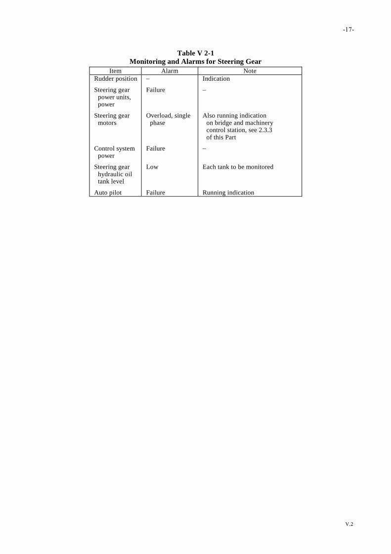
-17-
V.2
Table V 2-1
Monitoring and Alarms for Steering Gear
Item Alarm Note
Rudder position
Steering gear power units, power
Steering gear motors
Control system power
Steering gear hydraulic oil tank level
Auto pilot
Failure
Overload, single phase
Failure
Low
Failure
Indication
Also running indication on bridge and machinery control station, see 2.3.3 of this Part
Each tank to be monitored
Running indication

-18-
V.3
Chapter 3
Generators
3.1 General
3.1.1 Generators are to comply with the relevant part of IEC Publication 92, or an acceptable and relevant National
Standard, and the requirements of this Chapter.
3.1.2 The rotating parts of machines are to be so balanced that when running at any speed in the normal working
range the vibration does not exceed the levels of IEC 34 Rotating electrical machines Part 14.
3.2 Prime Movers
3.2.1 Governors on prime movers driving generating sets are to be capable of maintaining the speed within the
following limits:
(a) Momentary variations are to be 10% of the maximum rated speed when the rated load of the generator is
suddenly thrown off.
(b) Momentary variations are to be 10% of the maximum rated speed when 50% of the rated load of the
generator is suddenly thrown on followed by the remaining 50% load thrown on after an interval to restore
the steady state. The speed is to return to within 1% of the final steady speed in no more than 5 seconds.
When difficulty arises to meet the above requirements or when an installation requires different
characteristics, this will be considered.
(c) At all loads between no load and rated load the permanent speed variation is not to be more than 5% of the
maximum rated speed.
3.2.2 Generators driven by diesel engines of 37 kW and over with forced lubrication are to be provided with a
means to shut down the engine automatically in case of failure of the lubricating system.
3.2.3 For A.C. generating sets operating in parallel, the governors on prime movers are to be such that the load
sharing specified in 3.5.5 of this Chapter is ensured and facilities are to be provided to adjust the governor sufficient to
permit a load adjustment, at normal frequency, within 5% of full load.
3.3 Generator Construction
3.3.1 Every generator is to be fitted with a name plate of corrosion resistant material clearly marked with the
following items of information:
(a) Maker’s name and serial number.
(b) Nature of current (D.C. or A.C.) and kind of rating (if the generator is designed for continuous rating it
need not be mentioned).
(c) Rated output, voltage, current and speed.
-19-
V.3
(d) For D.C. generators type of winding.
(e) For A.C. Generators number of phases, rated frequency, power factor, exciting current and voltage.
(f) Temperature rise at rated load and design ambient temperature.
3.3.2 Insulating materials used in the construction of generators are to be at least of Class A insulation. When the
weight of the generators excluding shaft is over 500 kg, it is to be provided with means to prevent moisture
condensation in the machine when it is not running.
3.3.3 The lubrication arrangement for bearings are to be effective under all operating conditions including the
maximum ship inclinations defined by 1.4 and there are to be effective means provided to ensure that lubricant does
not reach the machine windings or other conductors and insulators.
3.3.4 Means are to be taken to prevent the ill effects of the flow of currents circulating between the shaft and
machine bearings or bearings of connected machinery.
3.3.5 Every generator terminal is to be protected against accidental contact, mechanical damage and where
necessary against dripping and moisture by the drip proof enclosure.
3.3.6 External frames, spiders and brackets are to be of rigid construction. Where welding is applied to shafts of
machines for securing arms or spiders, stress relieving is to be carried out after welding.
3.3.7 Brushes for commutator or slip rings are to be provided with flexible copper connections and are staggered
longitudinally along commutators in such a manner that the whole surface of the commutators is swept by the brushes
so that the formation of ridge will be prevented.
3.3.8 A provision is to be made for supplying the necessary amount of cool air and removing hot air, and to avoid
as far as possible the admission of moisture or oil vapour.
3.4 Direct Current Service Generators
3.4.1 Automatic voltage regulators are to be provided for shunt wound direct current generators.
3.4.2 Direct current generators used for charging batteries without series-regulating resistors are to be either:
(a) Shunt wound, or
(b) Compound wound with switches arranged so that the series winding can be switched out of service.
3.4.3 Where manual adjustment of terminal voltage is necessary for the satisfactory operation of generators the
facilities are to be provided at the switchboard or at an appropriate control position.
3.4.4 For each direct current generator, coupled to its prime mover, at any temperature within the working range
the means provided is to be capable of adjusting the voltage at any load between no load and full load to within:
(a) 0.5% of rated voltage for generators of rating exceeding 100 kW, and
(b) 1.0% of rated voltage for generators of rating not exceeding 100 kW.

-20-
V.3
3.4.5 The inherent regulation of the service generators is to be such that the following conditions are satisfied:
(a) For shunt or stabilized shunt wound generators when the voltage has been set at full load, the steady
voltage at no load is not to exceed 115% of the full load value, and the voltage obtained at any intermediate
value of load is not to exceed the no load value.
(b) For compound wound generators with the generator at full load operating temperature, and starting at 20%
load with voltage within 1% of rated voltage, then at full load the voltage is to be within 1.5% of rated
voltage. The average of the ascending and descending load/voltage curves between 20% load and full load
is not to vary more than 3% from rated voltage.
Note: For compound-wound generators operated in parallel, the drop in voltage may be acceptable up to
4% of the rated voltage when the load is gradually increased from 20% load to full load.
(c) Three-wire generator.
In addition to compliance with the requirements in (a) and (b), when operating at the rated current on the
heavier loaded side, i.e., either positive or negative lead, with the rated voltage between the positive and
negative leads and a current of 25% of the generator current rating in the neutral wire, the resulting
difference in voltage between the positive and neutral leads or the negative and neutral leads is not to
exceed 2% of the rated voltage between the positive and negative leads.
3.4.6 When D.C. generators are operated in parallel, the load on any generator is not to differ more than 10% of
its rated output of the largest machine from its proportionate share, based on the generator ratings, of the combined
load, for any steady-state condition in the combined load between 20% and 100% of the sum of the rated outputs of all
the machines. The starting point for the determination of the foregoing load distribution requirement is to be at 75%
load with each generator carrying its proportionate share.
3.4.7 The series field winding of each two-wire compound-wound generator is to be connected to the negative
terminal.
3.4.8 Equalizer connections are to be have a cross-sectional area appropriate to the system but in no case less than
50% of that of the negative connection from the generator to the switchboard.
3.5 Alternating Current Service Generators
3.5.1 Each alternating current service generator, unless of the self-regulating type, is to be provided with automatic
means of voltage regulation.
3.5.2 The voltage regulation of any alternating current generator with its regulating equipment is to be such that at
all loads from zero to full load the rated voltage at rated power factor is maintained under steady conditions within
2.5%, except that for emergency generators the limits may be within 3.5%.
3.5.3 Generators, and their excitation systems, when operating at rated speed and voltage on no-load are to be
capable of absorbing the suddenly switched, balanced, current demand of the largest motor or load at a power factor
not greater than 0.4 with a transient voltage dip which does not exceed 15% of rated voltage. The voltage is to be
recover to rated voltage within a time not exceeding 1.5 seconds.
3.5.4 The transient voltage rise at the terminals of a generator is not to exceed 20% of rated voltage when rated
kVA at a power factor not greater than 0.8 is thrown off.
3.5.5 Generators required to run in parallel are to be stable from no load (kW) up to the total combined full load
(kW) of the group, and load sharing is to be such that the load on any generator does not normally differ from its

-21-
V.3
proportionate share of the total load by more than 15% of the rated output (kW) of the largest machine or 25% of the
rated output (kW) of the individual machine whichever is less.
3.6 Exciters
3.6.1 Excitation current for ship's service and emergency generators is to be provided by attached rotating exciters
or by static exciters deriving their source of power from the machine being excited.
3.6.2 Propulsion generators are to be provided with at least two different means of excitation. The current derived
from the ship’s service power or lighting set may be taken as one means of excitation.
3.6.3 AC and DC rotating exciters are to conform to all applicable requirements for generators.
3.6.4 Arrangements for electric propulsion generators are to be such that propulsion can be maintained in case of
failure of an excitation system or failure of a power supply for an excitation system. Propulsion may be at reduced
power under such conditions where two or more propulsion generators are installed provided such reduced power is
sufficient to provide for a speed of not less than 7 knots or 12
of design speed whichever is the lesser.
3.7 Short Circuit Conditions
3.7.1 Service generators are to be capable of withstanding the mechanical and thermal effects of fault current for
the duration of any time delay which may be fitted in a tripping device of discrimination purposes. They are to be
capable of maintaining under steady state short-circuit conditions a current of at least three times the full load rated
current for a duration of 2 seconds or, where precise data is available, for the duration of any time delay which may be
fitted in a tripping device for discrimination purposes.
3.8 Testing and Inspection
3.8.1 Temperature rise test.
(a) The temperature rise of a generator of continuous rating is to be determined by a run at full load for a
duration until a final steady temperature has been reached. The maximum permissible temperature rise of a
generator is not to exceed the limit given in Table V 3-1.
(b) Where the ambient temperature has been assured to be in excess of the standard ambient temperature the
temperature rise is to be reduced according to 1.3.3 of this Part.
3.8.2 Insulation resistance test.
The insulation resistance of a generator is to be measured with a D.C. voltage of about 500 V preferably at the
conclusion of the temperature rise test of the machine. The insulation resistance of the circuit is not to be less than:
3×Rated voltage of the machine (V)
Rated output (kW or kVA) + 1000 (M)
3.8.3 High voltage test.
(a) The dielectric strength of the insulation of a generator is to be tested by an A.C. voltage of practically sine
wave form applied between the terminal and the frame of the machine which has been completely
assembled in a state of normal working condition for a period of 1 minute. The winding which is not under
test is to be connected to the ground.

-22-
V.3
(b) The standard testing voltage is to be as given in Table V 3-2. The frequency of the testing voltage is to be
25 to 100 Hz.
(c) In case of a repaired generator the above dielectric test is to be carried out using a test voltage equal to 75%
of the value specified in Table V 3-2.
3.8.4 Generators are to comply with the requirements in 3.4.5 or 3.5.2 by conducting the voltage regulation test.
3.8.5 Generators operated in parallel are to comply with the requirements in 3.4.6 or 3.5.5 by conducting the
parallel operation test.
3.8.6 Other tests.
(a) A.C. generators are to be capable of carrying a momentary overload of 50% in current for 2 minutes, D.C.
generator are to be capable of carrying a momentary overload of 50% in current for 15 seconds without
injury.
The test is to be carried out immediately after the temperature rise test as mentioned in 3.8.1 of this Part,
and the voltage, revolutions and frequency of the generators are to be maintained as near the rated values as
possible.
(b) Generators are to be capable of withstanding overspeed for two minutes according to the following
requirements:
(i) Turbine driven 115% of rated speed
(ii) Diesel driven 120% of rated speed
(iii) All others 125% of rated speed
(c) The commutation of the generator is to be clear of any objectionable sparking when running from no load
to full load. This examination is preferably to be carried out at the conclusion of the temperature rise test.
(d) Performance test of the generator is to be carried out after the machine has been installed on ship in
accordance with 12.3.2 of this Part.
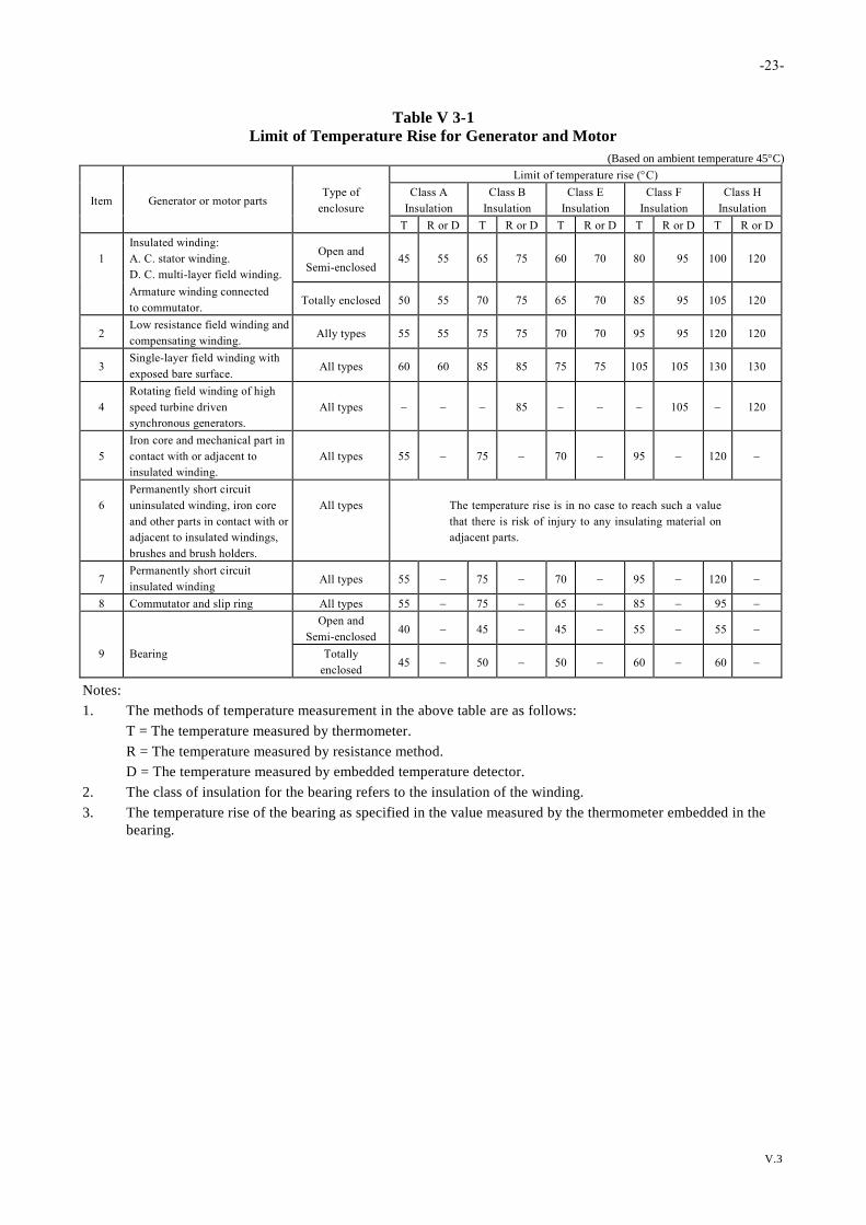
-23-
V.3
Table V 3-1
Limit of Temperature Rise for Generator and Motor
(Based on ambient temperature 45C)
Limit of temperature rise (C)
Item Generator or motor parts Type of
enclosure
Class A
Insulation
Class B
Insulation
Class E
Insulation
Class F
Insulation
Class H
Insulation
T R or D T R or D T R or D T R or D T R or D
1
Insulated winding:
A. C. stator winding.
D. C. multi-layer field winding.
Open and
Semi-enclosed
45
55
65
75
60
70
80
95
100
120
Armature winding connected
to commutator. Totally enclosed 50 55 70 75 65 70 85 95 105 120
2 Low resistance field winding and
compensating winding. Ally types 55 55 75 75 70 70 95 95 120 120
3 Single-layer field winding with
exposed bare surface. All types 60 60 85 85 75 75 105 105 130 130
4
Rotating field winding of high
speed turbine driven
synchronous generators.
All types
85
105
120
5
Iron core and mechanical part in
contact with or adjacent to
insulated winding.
All types
55
75
70
95
120
6
Permanently short circuit
uninsulated winding, iron core
and other parts in contact with or
adjacent to insulated windings,
brushes and brush holders.
All types
The temperature rise is in no case to reach such a value
that there is risk of injury to any insulating material on
adjacent parts.
7 Permanently short circuit
insulated winding All types 55 75 70 95 120
8 Commutator and slip ring All types 55 75 65 85 95
Open and
Semi-enclosed 40 45 45 55 55
9 Bearing Totally
enclosed 45 50 50 60 60
Notes:
1. The methods of temperature measurement in the above table are as follows:
T = The temperature measured by thermometer.
R = The temperature measured by resistance method.
D = The temperature measured by embedded temperature detector.
2. The class of insulation for the bearing refers to the insulation of the winding.
3. The temperature rise of the bearing as specified in the value measured by the thermometer embedded in the
bearing.
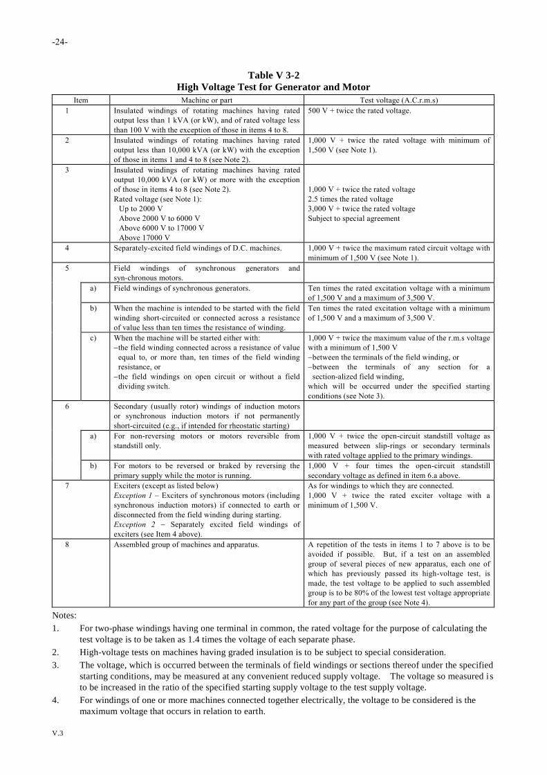
-24-
V.3
Table V 3-2
High Voltage Test for Generator and Motor
Item Machine or part Test voltage (A.C.r.m.s)
1 Insulated windings of rotating machines having rated
output less than 1 kVA (or kW), and of rated voltage less
than 100 V with the exception of those in items 4 to 8.
500 V + twice the rated voltage.
2 Insulated windings of rotating machines having rated
output less than 10,000 kVA (or kW) with the exception
of those in items 1 and 4 to 8 (see Note 2).
1,000 V + twice the rated voltage with minimum of
1,500 V (see Note 1).
3 Insulated windings of rotating machines having rated
output 10,000 kVA (or kW) or more with the exception
of those in items 4 to 8 (see Note 2).
Rated voltage (see Note 1):
Up to 2000 V
Above 2000 V to 6000 V
Above 6000 V to 17000 V
Above 17000 V
1,000 V + twice the rated voltage
2.5 times the rated voltage
3,000 V + twice the rated voltage
Subject to special agreement
4 Separately-excited field windings of D.C. machines. 1,000 V + twice the maximum rated circuit voltage with
minimum of 1,500 V (see Note 1).
5 Field windings of synchronous generators and
syn-chronous motors.
a) Field windings of synchronous generators. Ten times the rated excitation voltage with a minimum
of 1,500 V and a maximum of 3,500 V.
b) When the machine is intended to be started with the field
winding short-circuited or connected across a resistance
of value less than ten times the resistance of winding.
Ten times the rated excitation voltage with a minimum
of 1,500 V and a maximum of 3,500 V.
c) When the machine will be started either with:
the field winding connected across a resistance of value
equal to, or more than, ten times of the field winding
resistance, or
the field windings on open circuit or without a field
dividing switch.
1,000 V + twice the maximum value of the r.m.s voltage
with a minimum of 1,500 V
between the terminals of the field winding, or
between the terminals of any section for a
section-alized field winding,
which will be occurred under the specified starting
conditions (see Note 3).
6 Secondary (usually rotor) windings of induction motors
or synchronous induction motors if not permanently
short-circuited (e.g., if intended for rheostatic starting)
a) For non-reversing motors or motors reversible from
standstill only.
1,000 V + twice the open-circuit standstill voltage as
measured between slip-rings or secondary terminals
with rated voltage applied to the primary windings.
b) For motors to be reversed or braked by reversing the
primary supply while the motor is running.
1,000 V + four times the open-circuit standstill
secondary voltage as defined in item 6.a above.
7 Exciters (except as listed below)
Exception 1 Exciters of synchronous motors (including
synchronous induction motors) if connected to earth or
disconnected from the field winding during starting.
Exception 2 Separately excited field windings of
exciters (see Item 4 above).
As for windings to which they are connected.
1,000 V + twice the rated exciter voltage with a
minimum of 1,500 V.
8 Assembled group of machines and apparatus. A repetition of the tests in items 1 to 7 above is to be
avoided if possible. But, if a test on an assembled
group of several pieces of new apparatus, each one of
which has previously passed its high-voltage test, is
made, the test voltage to be applied to such assembled
group is to be 80% of the lowest test voltage appropriate
for any part of the group (see Note 4).
Notes:
1. For two-phase windings having one terminal in common, the rated voltage for the purpose of calculating the
test voltage is to be taken as 1.4 times the voltage of each separate phase.
2. High-voltage tests on machines having graded insulation is to be subject to special consideration.
3. The voltage, which is occurred between the terminals of field windings or sections thereof under the specified
starting conditions, may be measured at any convenient reduced supply voltage. The voltage so measured i s
to be increased in the ratio of the specified starting supply voltage to the test supply voltage.
4. For windings of one or more machines connected together electrically, the voltage to be considered is the
maximum voltage that occurs in relation to earth.
-25-
V.4
Chapter 4
Motors
4.1 General
4.1.1 The requirements for the construction, materials, insulation, lubrication and testing of motors are the same as
those for generators as specified in 3.3, 3.8.1, 3.8.2 and 3.8.3 of this Part except the means is to be provided for
propulsion motors to prevent moisture condensation when motors are idle for appreciable periods. See 3.3.2 of this
Part.
4.1.2 Motors for essential service when installed with their rotor shafts not in fore and aft direction, the lubrication
will require special consideration.
4.1.3 All propulsion and essential service motors are to be of continuous rating except those for deck machinery
which may be of non-continuous rating.
4.1.4 The standard application for types of enclosures of motors is to be as follows:
(a) In the engine room or spaces where motors are subject to mechanical injury, or dripping of oil or water are
to have an enclosure of at least IP22 protection. Motors below the level of the floor plates are to have an
enclosure of at least IP44 protection.
(b) In galleys, toilets, washing rooms and similar spaces, use an enclosure of at least IP44 protection.
(c) In the wheelhouse, the chart room, the radio room, the public saloon, offices, stores, living places passages
and the pantry, use an enclosure of at least IP20 protection.
(d) On the weather deck, use a protection enclosure of IP56 or enclose motors in metal housing, giving the
same protection.
4.2 Testing and Inspection
4.2.1 Temperature rise test.
The temperature rise of a motor of continuous rating is to be in accordance with the requirements for generator in 3.8.1
of this Part and the maximum permissible temperature rise is not to exceed those given in Table V 3-1.
4.2.2 Insulation resistance test.
The insulation resistance for motors is to be in accordance with the requirements set forth in 3.8.2 of this Part.
4.2.3 High voltage test.
The dielectric strength of the insulation of motors is to be in accordance with the requirements set forth in 3.8.3 of this
Part.
4.2.4 Other tests.

-26-
V.4
(a) After the temperature rise test, motors of continuous ratings, except those of non-continuous ratings or
special types, are to withstand the following excess torque test by maintaining the voltage, revolving speed
and frequency as near their rated values as possible:
(i) D.C. motors 50% 15 seconds
(ii) Synchronous motors 50% 15 seconds
(iii) Induction motors 60% 15 seconds
(b) Motors of non-continuous ratings or special types, the excess torque test is to be specially considered.
(c) The excess torque test for propulsion motors is to be specially considered for each installation.
(d) The commutation of motors is to be clear of any objectionable sparking when running under all conditions
of load and field adjustment.
(e) Overspeed tests.
Motors are to be capable of withstanding overspeed for two minutes according to the following
requirements:
(i) Shunt-wound motors 125% of rated speed
(ii) Series-wound motors 200% of rated speed
(iii) Compound-wound motors 125% of no load speed
(iv) Synchronous motors 125% of synchronous speed
(v) Induction motors 125% of synchronous speed.

-27-
V.5
Chapter 5
Switchboards and Mounted Equipment
5.1 General
5.1.1 The switchboard is to be placed in an accessible and well-ventilated position, free from inflammable gas, acid
fume, and not exposed to mechanical injury or damage from water, steam or oil. Unobstructed clearance for operation
and ample space to permit maintenance are to be maintained.
5.1.2 Where necessary, the space at the rear of switchboards is to be ample to permit maintenance and in general
not less than 0.6 m except that this may be reduced to 0.5 m in way of stiffeners or frames.
5.1.3 The arrangement of the main system of supply is to be such that a fire or other casualty in spaces containing
the main source of power, associated transforming equipment, if any, the main switchboard and the main lighting
switchboard will not render the emergency services inoperative.
5.1.4 The arrangement of the emergency system of supply is to be such that a fire or other casualty in spaces
containing the emergency source of power, associated transforming equipment, if any, the emergency switchboard and
the emergency lighting switchboard, will not render the essential services inoperative.
5.1.5 The main switchboard is to be so placed relative to the main source of power that, as far as is practicable, the
integrity of the main system of supply will be affected only by a fire or other casualty in one space.
5.1.6 The sides and the rear and, where necessary, the front of switchboard are to be suitably guarded.
5.1.7 Insulated handrails are to be provided on the front and rear faces of switchboard, and where necessary,
non-conducting mats or gratings are to be provided at front and rear of the switchboard.
5.1.8 The dead front type switchboard is to be used where the voltage to ground or between poles is in excess of
50V, D.C. or 50V, AC. root mean square.
5.1.9 Earth indicating lamps is required for every insulated distribution system, whether primary or secondary, for
power, heating or lighting circuits.
5.2 Construction
5.2.1 Switchboard panels are to be made of permanent high dielectric strength insulating materials of adequate
strength such as impregnated ebony asbestos, laminated phenolic material or the equivalent. They may be made of
metal if all conducting parts are to be insulated from the panels with bushes and washers of mica or other
non-absorbent insulating material.
5.2.2 No wood is to be used in the construction or installation of switchboards except the non-conducting handrails
installed in front of the panels as required by 5.1.7 of this Part.
5.2.3 Cable entries of a switchboard are to be so constructed that no ingress of water into the switchboard is
permitted along the cables.
-28-
V.5
5.2.4 Every live part is to be suitably spaced or shielded with non-ignitable insulating material that any arc cannot
be maintained between the working parts or between such parts and earth.
5.2.5 The apparatus, measuring instruments, circuit breakers, switches and operating handles are each to be
provided with a name plate bearing a clear indelible indication for identification. The rating of the fuse, current rating
of the circuit breaker and the cross sectional area of the cables which these devices protected are also to be marked on
labels placed in suitable positions.
5.2.6 Section and distribution boards are to be suitably enclosed unless they are installed in a cupboard or
compartment to which only authorized persons have access, in which case the cupboard may serve as an enclosure.
5.2.7 All enclosures are to be constructed of, or lined with, non-flammable and non-hygroscopic material, and are
to be of robust construction.
5.3 Bus Bars
5.3.1 Bus bars and their connections are to be made of copper and provided with anti-corrosion and oxidization
surfaced contact. All joints are to be provided with locking devices to prevent loosening due to vibration.
5.3.2 The cross section of bus bars is to be such that the maximum permissible temperature rise of 45C as
measured by the thermometer is not to be exceeded when carrying full load current.
5.3.3 A clearance is to be maintained between the bare metal part and the bus bar according to Table V 1-2.
5.3.4 The current rating of equalizer connections and equalizer switches is to be not less than half the rated full load
current of the generator. The current rating of equalizer busbars is to be not less than half the rated full load current of
the largest generator in the group.
5.3.5 Busbars and busbar connections are to be so supported as to withstand the electromagnetic force resulted
from short-circuiting.
5.4 Switchboard Wiring and Circuit Arrangement
5.4.1 Wiring.
(a) All the wiring on the switchboard for the voltmeter, wattmeter, voltage coil, synchroscope, pilot lamp (if
any) and earth lamp are to be protected by a fuse on each insulated pole.
(b) The instrument and the control wiring are to be of the stranded type, heat-resisting and flame retarding
insulation. Wiring from the hinged panel is to be of extra flexible type. The secondary winding of
instrument transformers are to be earthed.
(c) Ducts and straps for wiring are to be of flame-retardant materials.
(d) Insulated wires for control and instrument circuits are not to be bunched together with wires for main
circuits and not to be in the same duct. However, if the rated voltages and maximum permissible
temperatures of conductors are the same each other and no injurious effects are imposed by the main
circuits, this requirement may not be applied.
-29-
V.5
5.4.2 Fuses, except those for instruments and control circuit, are to be mounted on or be accessible from the front
of the switchboard.
5.4.3 Switches, circuit breakers and contactors are, whenever practicable to be so connected that their blades or
moving parts are not alive in the off or de-energized position.
5.4.4 The switch and fuse fitted on the same pole are to be so arranged that the fuse is not alive when the
corresponding switch is in the off position.
5.4.5 Metal frames, metal cases of instruments and the secondary winding of instrument transformers of
switchboards are to be effectively earthed.
5.4.6 Where rheostats or other devices that may operate at high temperature are amounted on the switchboard, they
are to be naturally ventilated, isolated by barries or separately mounted from the switchboard as necessary in order to
prevent excessive temperature of adjacent device.
5.5 Circuit-Breakers and Electromagnetic Contactors
5.5.1 Circuit-breakers are to comply with IEC Pulibcation 947-1 and 947-2, or 158-1 or equivalent therto, amended
when necessary for ambient temperature, and also to comply with the requirements in (a) and (b).
(a) The construction of circuit-breakers is to comply with the following:
(i) All circuit-breakers are to be of trip-free type and depending upon the field of their application, the
trip attachments are to have a time-delay or an instantaneous overcurrent trip feature or both of
them.
(ii) The main contacts of the circuit-breakers are to be such as to have no undue burning or pitting.
Arcing contacts except those of the moulded case circuit-breakers are to be readily renewable.
(iii) Instantaneous trip devices other than those of electronic type having suitable testing arrangements
are to be of a construction capable of tripping the associated breaker directly by short-circuit
current.
(iv) Circuit-breakers are to be such that no accidental opening and closing occur due to the vibration of a
ship, and furthermore, no malfunction is caused by the list of an angle of 30 in any direction.
(v) The fused circuit-breakers of moulded-case type are to be so constructed that single phasing does
not occur in the event of blowing of fuses and that the fuses can be readily replaced without the risk
of accidental touch for the operating personnel to their live-parts.
(vi) On each circuit-breaker the rated (operational) voltage and rated (thermal) current, and in addition
rated breaking capacity, rated making current and rated short-time current are to be clearly indicated
according to its kind. Each time-delay overcurrent trip device is to be indicated of its operating
characteristics, except the moulded-case circuit-breakers.
(b) Performance of circuit-breakers is to comply with the following:
(i) The temperature rise in the connecting terminals of cables is not to exceed 45C at an ambient
temperature of 45C when 100% of the rated current is carried therethrough.
(ii) All circuit-breakers are, according to their kind, to be such as to be able to securely break the
over-current not more than the rated breaking capacity and safely make the circuit to carry the
current not more than the rated making current under the circuit conditions specified in the
standards referred to in 5.5.1.
(iii) The time-delay over-current trip devices of circuit-breakers for generator circuits are to be such that
the readjustment of the current setting does not cause remarkable change to the time-delay feature.
(iv) The characteristics of the time-delay overcurrent trip devices are not to be affected excessively by
ambient temperature.

-30-
V.5
5.5.2 Circuit-breakers of moulded-case type are to be mounted or arranged in such a manner that the breakers may
be removed from the front without disconnecting conductors or de-energizing the supply to the breakers.
5.5.3 Electromagnetic contactors are to comply with IEC publication 947-1 and 947-4, or 158-1 or equivalent
thereto, amended when necessary for ambient temperature, and also to comply with the requirements in (a) and (b).
(a) The construction of electromagnetic contactors is to comply with the following:
(i) Electromagnetic contactors are to be such that no accidental opening and closing occur due to the
vibration of the ship, and furthermore, no malfunction is caused by the list of an angle of 30 in any
direction.
(ii) The contact pieces and magnetic coils are to be readily replaceable.
(iii) Each electromagnetic contactor is to be clearly indicated of its rated operational voltage, rated
capacity or full load current corresponding to rated capacity, rated operational voltage and
frequency for control circuits, interruption current capacity and closed circuit current capacity. Such
indication may be made in terms of value or symbol.
(b) The performance of electromagnetic contactors is to comply with the following:
(i) The temperature rise in the connecting terminals of cables is not to exceed 45C at an ambient
temperature of 45C when the full load current corresponding to the rated capacity is carried
therethrough.
(ii) Electromagnetic contactors are to have a suitable interruption current capacity and closed-circuit
current capacity depending on their application.
(iii) Electromagnetic contactors are not to accidentally open the circuit at a voltage exceeding 85% of
the rated voltage.
5.6 Fuses
5.6.1 Fuses are to comply with IEC Publication 269 or equivalent thereto, amended when necessary for ambient
temperature, and also to comply with the requirements in (a) and (b).
(a) The construction of fuses is to comply with the following:
(i) Fuses are to be of enclosed type and the construction is to be such that its enclosure is not broken
nor burnt and the adjacent insulation is not deteriorated by flowing of fused metal or emitting of
gases, when the fuse element has blown out.
(ii) Fuses are to be readily replaceable with spares without the risk of causing electric shock or burn on
setting fuses in and out.
(iii) Each fuse is to be clearly indicated of its rated voltage and rated current, and in addition rated
breaking capacity, fusing characteristics and current-limiting characteristics according to its kind.
Such indication may be made in terms of value or symbol.
(b) The performance of fuses and fuse-holders are to comply with the following:
(i) The temperature rise in the connecting terminals of cables is not to exceed 45C at an ambient
temperature of 45C when the fuses and fuse-holders have been fitted to the normal working
condition and 100% of the rated current is carried therethrough.
(ii) Fuses are to have the fusing characteristics corresponding to their kind, and under the circuit
conditions specified in the standards referred to in (a), they are to be capable of breaking securely
all currents whichever is below the rated breaking capacity and above the fusing current.
5.7 Instruments
5.7.1 The limit of the scale of every voltmeter is to be approximately 120% of the normal voltage of the circuit.

-31-
V.5
5.7.2 The limit of the scale of every ammeter is to be approximately 130% of the current rating of the circuit in
which the ammeter is connected. Ammeters for use with D.C. generators or wattmeters for use with A.C. generators
which may operate in parallel are to be capable of indicating a reverse current or power of at least 15% of the rated full
load current or power of the generator respectively.
5.7.3 The minimum number of instruments to be provided for every main or emergency switchboard is to be as
follows:
(a) 2-wire D.C. system:
(i) For each generator not arranged for parallel operation:
(1) 1 ammeter, and
(2) 1 voltmeter.
(ii) For generators arranged for parallel operation:
(1) 1 ammeter for each generator, and
(2) 1 voltmeter for each generator with voltmeter switch to enable it to indicate generator voltage,
bus voltage. One of these voltmeter switches is to indicate shore connection voltage.
(b) 3-wire D.C. system:
(i) For each generator not arranged for parallel operation:
(1) 2 ammeters for each generator, 1 in positive and 1 in negative line, and
(2) 1 voltmeter provided with switch for connecting the voltmeter to indicate generator voltage
positive to negative, positive to neutral and neutral to negative.
(ii) For generators arranged for parallel operation:
(1) 2 ammeters per generator, and
(2) 1 voltmeter for each generator with switch for connecting the voltmeter to indicate generator
voltage, positive to negative, positive to neutral and neutral to negative, and bus voltage
positive to negative. One of these voltmeter switches is to indicate shore connection voltage,
positive to negative, positive to neutral, and neutral to negative.
(c) 3-phase A.C. system:
(i) For each generator not arranged for parallel operation:
(1) 1 voltmeter for each generator with switch to indicate voltage between phases,
(2) 1 ammeter provided with selector switch to indicate the current of each phase,
(3) 1 frequency meter provided with selector switch to indicate the frequency of any generator, and
(4) 1 wattmeter for each generator (it may be omitted for 50 kVA or less).
(ii) For generators arranged for parallel operation:
(1) 1 voltmeter for each generator with a selector switch to indicate the voltage of each phase of
the generator and one phase of the bus. One of these voltmeter switches is to indicate voltage
of shore connection,
(2) 1 ammeter for each generator provided with a selector switch to indicate the current of each
phase,
(3) 1 indicating wattmeter for each generator,
(4) 1 synchroscope and synchronizing lamp provided with selector switch of synchroscope for
paralleling in any combination when more than 2 generators are installed,
(5) 2 frequency meters provided with selector switch to indicate the frequency of any generator
and bus bar, and
(6) 1 ammeter for exciter per generator, if necessary.

-32-
V.5
5.8 Testing and Inspection
5.8.1 The temperature rise of the switchboard equipment and bus bars under rated current, rated voltage and rated
duty operation are to be ascertained that they are not to exceed the values as specified in Table V 5-1 and 5.3.2 of this
Part.
5.8.2 The dielectric strength of switchboards is to be tested by continuous application of 50 or 60 Hertz alternating
sine wave e.m.f. between all current carrying parts and earthed frame, and between current carrying parts of opposite
polarity or phase according to the requirements as shown in Table V 5-2.
5.8.3 Immediately after completion of the dielectric strength test, the insulation resistance of switchboards between
current carrying parts of each polarity and earth, and between current carrying parts of opposite polarity or phase is to
be not less than 1 M when tested with D.C. voltage of approximately 500V tester. The test may be made with circuit
breakers and switches connected to the outgoing circuit in open position and the fuse link for the pilot lamp, earth
lamp, voltmeter, etc. removed. Voltage coils normally connected to bus bars may be temporarily disconnected while
the test between poles is being made.
5.8.4 Functions of instruments, circuit-breakers, switchgears, etc. on switchboards are to be confirmed normal.

-33-
V.5
Table V 5-1
Limits of Temperature Rise of Electrical Appliances for Switchboard
(Based on ambient temperature 45C)
Items and parts
Limit of temperature rise
(C)
Thermometer method Resistance method
Class A insulation 45 65
Coils Class E insulation 60 80
Class B insulation 75 95
Bare windings of single layer 75
Mass form Copper or Copper alloy 40
Silver or Silver alloy 70
Contact pieces Multilayer form Copper or Copper alloy 25
Knife form Copper or Copper alloy 25
Terminals for external cables 45
Moulded-case type 245
Those other than For continuous service 295
Metallic resistors Moulded-case type For intermittent service 345
Exhaust (approx. 25 mm above the exhaust port 170
Table V 5-2
Dielectric Strength Test of Switchboards
Rated voltage
(V)
Testing voltage
(V)
Testing period
(s)
60
250
500
500
1500
2000
60
60
60

-34-
V.6
Chapter 6
Batteries
6.1 General Construction and Arrangement
6.1.1 Batteries used for power, lighting or internal communication are to be so constructed as to prevent spilling of
the electrolyte due to the motion of the ship to the surrounding objects and to be installed permanently in adequately
ventilated spaces not subjected to the extremes of temperature.
6.1.2 Batteries are not to be placed in sleeping quarters.
6.1.3 Lead type batteries and alkaline type batteries are not to be placed in the same compartment.
6.1.4 Large batteries are to be installed in a compartment assigned to them only. A box on deck would meet this
requirement if adequately ventilated and provided with means to prevent ingress of water.
6.1.5 Engine starting batteries are to be located as close as practicable to the engine(s) served. If such batteries
cannot be accommodated in the battery compartment, they are to be installed so that adequate ventilation is ensured.
6.1.6 Battery compartments are to be ventilated by an independent ventilating system.
6.1.7 Natural ventilation may be employed if ducts can be run directly from the top of the compartment to the open
air with no part of the duct more than 45 from the vertical. If natural ventilation is impracticable, mechanical
ventilation is to be provided. Interior surfaces of ducts and fans are to be painted with corrosion-resistant paint. Fan
motors are not to be located in the air stream. Ventilating fans are to be so constructed and to be of such a material as
to render sparking impossible in the event of the impeller touching the fan casing.
6.1.8 Every battery is to be so arranged that each cell is readily accessible for replacing, inspection, testing,
replenishing and cleaning.
6.1.9 Switches, fuses and other electrical equipment liable to cause an arc are not normally be installed in battery
compartments. Where such equipment is necessary for operational reasons, the equipment is to be certified for group
IIC gases and temperature Class T1 in accordance with IEC Publication 79: Electrical apparatus for explosive gas
atmospheres, or an acceptable and relevant National Standard.
6.1.10 The exposed metal in the space or compartment used for the storage of batteries such as shelf, vent fan and
duct (if used) is to be protected with corrosion resistance paint. The deck, shelf, locker or box where acid batteries are
placed is to have a watertight lining of lead sheet of 1.6 mm. thick and not less than 100 mm. deep at all sides. For
alkaline batteries the shelf is to be similarly lined with steel, not less than 0.8 mm. thick.
6.2 Charging Facilities
6.2.1 Suitable means, including ammeters and voltmeters, are to be provided for controlling the current with which
batteries are to be charged and to protect against accidental discharge into the charging circuit. Fuses may be used for
the protection of emergency lighting batteries instead of circuit breakers up to and including 400 A rating.
6.2.2 Where a battery is connected for floating service or where it is used for supplying power whilst it is being
charged, the maximum battery voltage is not to exceed the permissible voltage of any of the connected appliances.

-35-
V.6
6.2.3 Where a low-voltage battery is connected for floating service, all connected apparatus should be capable of
withstanding the line voltage to earth and a device is to be provided for preventing excessively high voltages in the
battery circuit.
6.2.4 The charging equipment, except rectifiers, for all batteries with a voltage more than 20% of the line voltage is
to provide automatic protection against reversal of current.
6.2.5 The charging equipment is to be such that a completely discharged battery can be completely charged within
10 hours unless a shorter time is necessary. The maximum permissible current must not be exceeded during charging.
-36-
V.7
Chapter 7
Transformers
7.1 General
7.1.1 The requirements of this Chapter are normally applicable to marine use transformers having a rated output of
1 kVA or more for single phase and 5 kVA or more for 3-phase.
7.1.2 Transformers, unless otherwise approved, are to be rated at their continuous maximum rating expressed as the
kVA output on non-inductive load when carrying rated current on the output side with rated voltage applied on the
input side.
7.1.3 Where transformers are an essential part of the propulsion or ship’s service supply system, the system is to be
arranged to ensure at least the same continuity of supply as required in 11.2.1.
7.2 Construction
7.2.1 Transformers in accommodation spaces are to be of dry, naturally cooled type. In machinery spaces they may
be of oil-immersed, naturally cooled type.
7.2.2 Transformers except those for motor starting are to be double wound (two separate windings).
7.2.3 Oil-immersed transformers rated at 10 kVA or more are to be provided with oil gauges and drain cocks or
plugs, and those rated at 75 kVA or more with thermometers in addition.
7.3 Voltage Regulation
7.3.1 The secondary terminal voltage difference between no load and the rated current with a unity power factor,
expressed as a percentage of the no load secondary voltage, is not to exceed the following values:
(a) For up to 5 kVA per phase 5%
(b) For 5 kVA and over per phase 2.5%
7.3.2 The percentage error of the voltage ratio is to be within 0.5% of the declared ratio, or equal to 1
10 of the
percentage impedance voltage at rated load, whichever is the smaller.
7.4 Temperature Rise Test
7.4.1 The maximum permissible temperature rise at the continuos maximum rating is not to exceed the limit given
in Table V 7-1. The reference ambient temperature is based on temperature of cooling fluid equal to 45C for air.

-37-
V.7
7.5 Other Tests
7.5.1 Every transformer while in service is to be capable of withstanding short circuit without injury at normal
working voltage for the time period given in Table V 7-2. Transformers having an impedance voltage less than 4% are
to be capable of withstanding, under service condition, 25 times normal full load current for 2 seconds. These are to be
conducted as a type test.
7.5.2 The high voltage test is to be carried out immediately after the temperature rise test, by the continuous
application for 1 minute of alternating voltage specified in Table V 7-3 and under the frequency of 50 to 60 Hz.
(a) The test voltage as given in Table V 7-3 is to be applied between the primary winding under test and the
secondary winding and core all connected to earth.
(b) The test voltage as given in Table V 7-3 is to be applied between the secondary winding under test and the
primary winding and core all connected to earth.
7.5.3 A test voltage is to be applied to a winding of a transformer at approximately twice the rated frequency for a
duration of 60 seconds to induce voltage to a magnitude twice of the normal working voltage of the winding not
connected to the exciting source. When the test frequency exceeds twice the rated frequency the duration of the test is
to be equal to
60 2 Rated frequency
Test frequency seconds
but in no case the duration of the test is to be less than 15 seconds.
7.5.4 In the case of repaired transformer the above dielectric and induced high voltage tests are to be carried out
using test voltage equal to 75% of 7.5.2 and 7.5.3 above.

-38-
V.7
Table V 7-1
Limit of Temperature Rise for Transformer
(Based on ambient temperature 45C)
Cooling system of Limit of temperature rise (C)
Part transformer Measured
by
Class A
Insulation
Class B
Insulation
Class E
Insulation
Class F
Insulation
Class H
Insulation
Dry natural cooling
or dry air blast
Resistance
Method 55 75 70 95 120
Oil immersed
Resistance
Method 60
Oil Thermometer 45
Core The temperature rise when measured by thermometer on the external surface
of the core is not to exceed that permitted for the adjacent insulation.
Table V 7-2
Time Period of Short Circuit
Impedance voltage
(%)
Time period of
short circuit
(s)
4
5
6
7 and above
2
3
4
5
Table V 7-3
High Voltage Test
Rated voltage
(V)
Test voltage
(V)
up to 250
over 250
1500
1000 + 2 maximum
voltage between lines
Windings

-39-
V.8
Chapter 8
Cables
8.1 General
8.1.1 Cables are to comply with IEC Publication 92 or equivalent thereto. Installation of cables is to comply with
the requirements in this Chapter.
8.1.2 The rated voltage of any cable is not be lower than the nominal voltage of the circuit for which it is used.
8.1.3 Separate cables are, as a rule, to be used for a power supply circuit requiring individual short-circuit and
overcurrent protection.
8.2 Cable Applications
8.2.1 The maximum rated conductor temperature of the insulating material for normal operation is to be at least
10C higher than the maximum ambient temperature liable to be produced in the space where the cable is installed.
8.2.2 The application of insulating materials for cables is to be in accordance with Table V8-1.
8.2.3 Cable are to be protected by sheath and/or armour in accordance with the following requirements:
(a) Cables fitted up on weather decks, in bath room, in cargo holds, in machinery spaces or in any other
location where water condensation or oil vapour may be present, are to have a metallic sheath or an
impervious sheath (polyvinylchloride compound or polychloroprene compound).
(b) In permanently wet situations, metallic sheaths are to be used for cables with hygroscopic insulation.
(c) Cables are to be armoured except cables fitted up in living quarters or in any other location where they are
not exposed to risk of mechanical injury.
8.2.4 All electric cables and wiring external to equipment are to be at least of a flame retardant type and are to be so
installed as not to impair their original flame retarding properties. Where necessary for particular applications the
Society may permit the use of special types of cables such as radio frequency cables, which do not comply with the
foregoing.
8.3 Current Rating of Cables
8.3.1 The diversity factor of the individual loads may be taken into account in estimating the maximum continuous
load.
8.3.2 The voltage drop from main or emergency switchboard busbars to any current under normal conditions of
service, is not to exceed 6% of the nominal voltage. For supplies from batteries with a voltage not exceeding 55 volts,
these figures may be increased to 10%. For navigation lights and radio apparatus, lower voltage drops are to be
considered.

-40-
V.8
8.3.3 In assessing the current rating of lighting circuits, every lampholder is to be assessed at the maximum load
likely to be connected to it, with a minimum of 60 watts, unless the fitting is so constructed as to take only a lamp
rated at less than 60 watts.
8.3.4 Where motors used for windlasses and capstans are for short time duty, the current rating of the cables may
be allowed to increase according to their duty.
8.3.5 Current ratings of cables for continuous services are not to exceed the values given in Table V 8-2.
8.3.6 Where more than six electric cables, which may be expected to operate simultaneously at their full rated
capacity, are laid close together in a cable bunch in such a way that there is an absence of free air circulation around
them, a correction factor of 0.85 is to be applied. Signal cables may be exempted from this requirement.
8.3.7 The current ratings of Table V 8-2 are based on an ambient temperature of 45C. For other values of ambient
temperature the correction factors shown in Table V 8-3 are to be applied.
8.3.8 Current ratings of cables for short-time services and intermittent services are to be corrected as follows:
(a) The current rating of cables for short-time services (30 minutes or 60 minutes) may be increased by
multiplying the value given in Table V 8-2 by the following correction factor.
correction factor = T
ts
e1
12.1
where:
ts = 30 or 60 (min)
T = 0.245d1.35
where d is the overall diameter of the cable, in mm
(b) The current rating of cables for intermittent serviceds (for periods of 10 minutes, of which 4 minutes are
with a constant load and 6 minutes without load) may be increased by multiplying the value given in Table
V 8-2 by the following correction factor.
correction factor =1
1
10
4
e
e
T
T
where:
T = 0.245d1.35
where d is the overall diameter of the cable, in mm
(c) The current rating for other intermittent ratings is to be deemed appropriate by the Society.
8.3.9 The cross sectional area of the conductors is to be sufficient to ensure that, under short circuit conditions, the
maximum rated conductor temperature for short circuit operation is not exceeded, taking into consideration the time
current characteristics of the circuit protective device and the peak value of the prospective short circuit current.
8.3.10 Where cables are used to supply two or more final sub-circuits account may be taken of any diversity factors
which may apply (see 2.1.4).

-41-
V.8
8.4 Installation of Cables
8.4.1 Cables and wiring are to be installed and supported in such a manner as to avoid chafing or other damage.
Cable runs are to be, as far as possible, straight and accessible.
8.4.2 The installation of cables across expansion joints in the ship’s structure is to be, as far as possible, avoided.
Where such installation is unavoidable, a loop of cable of length proportional to the expansion of the joint is to be
provided. The internal radius of the loop is to be at least 12 times the external diameter of the cable.
8.4.3 Electric cables are to be as far as practicable installed remote from sources of heat. Where installation of
cables near sources of heat cannot be avoided and where there is consequently a risk of damage to the cables by heat,
suitable shields, insulation or other precautions are to be installed.
8.4.4 Cables having insulating materials with different maximum rated conductor temperatures are not to be
bunched together, or, where such bunching is unavoidable, the cables are to be operated so that no cable may reach a
temperature higher than that permitted for the lowest temperature rated cable in the group.
8.4.5 Cables having a protective covering which may damage the covering of other cables are not to be bunched
together with those cables.
8.4.6 Where a duplicate supply is required, the two cables are to follow different routes which are to be as far apart
as practicable.
8.4.7 When installing cables, the minimum inside radius of bend is to be in accordance with the following:
(a) Armoured rubber insulated and PVC insulated cables : 6d
(b) Unarmoured rubber insulated and PVC insulated cables :
4d (d 25 mm)
6d (d > 25 mm)
(c) Mineral insulated cables: 6d
d: overall diameter of the finished cable
8.4.8 Intrinsically safe circuits are to be installed complying with the followings;
(a) The cables for intrinsically safe circuits associated with intrinsically safe type electrical equipment are to
be of exclusive use, being installed separately from cables for general circuits.
(b) Intrinsically safe circuits associated with different intrinsically safe type electrical equipment are, as a rule,
to be wired individually using different cables. Where it is necessary to use a multi -core cable in common,
a cable which has shields by each core or each pair of cores is to be used, having such shields earthed
effectively. However, intrinsically safe circuits associated with category "ia" intrinsically safe type
electrical equipment are not to be contained in a cable associated with category "ib" intrinsically safe type
electrical equipment.
8.5 Precaution against Fire
8.5.1 Where electric cables are installed in bunches, provision is to be made to limit the propagation of fire, which
may be achieved by the use of suitably located fire stops. Alternative arrangements will be considered.

-42-
V.8
8.5.2 All cables for power, lighting, internal communications, signals and navigational aids of essential and
emergency services are to be so far as practicable routed clear of machinery spaces of category A and their casings,
galleys, laundries and other high fire risk areas. Cables connecting fire pumps to the emergency switchboard is to be of
a fire resistant type when they pass through high fire risk areas. All such cables are to be so far as practicable run in
such a manner as to preclude their being rendered unserviceable by heating of the bulkheads that may be caused by a
fire in an adjacent space.
8.6 Cables in Hazardous Areas
Where cables which are installed in hazardous areas introduce the risk of fire or explosion in the event of an electrical
fault in such areas, special precautions against such risks are to be taken to the satisfaction of the Society.
8.7 Mechanical Protection of Cables
8.7.1 Cables exposed to risk of mechanical damage are to be protected by metal channels or casings or enclosed in
steel conduct.
8.7.2 Cables in cargo holds and other spaces where there is exceptional risk of mechanical damage are to be
suitably protected, even if armoured.
8.7.3 Metal casings for mechanical protection of cables are to be efficiently protected against corrosion.
8.7.4 Non-metallic duct or conduit is to be of flame retardant material. PVC conduit is not to be used in refrigerated
spaces or on open decks.
8.8 Installation of Cables in Pipes and Conduits
8.8.1 Metallic pipes and conduits are to be effectively earthed and are to be mechanically and electrically
continuous across joints.
8.8.2 The internal radius of the bend of pipes and conduits is not to be less than the values specified in 8.4.7.
Where, however, pipes exceed 64 mm in diameter, the internal radius of the bend is not to be less than twice a
diameter of the pipe.
8.8.3 The drawing-in factor (ratio of the sum of the cross-sectional areas of the cables to the internal cross-
sectional area of the pipe) is not to exceed 0.4.
8.8.4 Horizontal pipes or conduits are to have suitable drainage.
8.8.5 Where pipe arrangement is long, expansion joints are to be provided where necessary.
8.9 Penetration Through Bulkheads and Decks
8.9.1 Penetration through bulkheads and decks, which are required to have some degree of strength and tightness, is
to be so effected as to ensure that the strength and tightness are not impaired.
8.9.2 Penetration through bulkheads and decks, which are required to have some degree of fire integrity, is to be so
effected as to ensure that the fire integrity is not impaired.

-43-
V.8
8.9.3 Where cables pass through non-watertight bulkheads or steel structure, holes are to be bushed with lead or
other suitable materials in order to avoid damage to cables. If the thickness of the steel is sufficient and there is no risk
of damage to cables, adequately rounded edges may be accepted as the equivalent of bushing.
8.10 Earthing and Securing of Cables
8.10.1 Metallic coverings of cables are to be effectively earthed at both ends, except that in final sub-circuits
earthing may be at the supply end only. This does not necessarily apply to instrumentation cables where single point
earthing may be desirable for technical reasons.
8.10.2 Effective means are to be taken to ensure that all metallic coverings of cables are made electrically
continuous throughout their length.
8.10.3 Lead sheath of lead-sheathed cables is not to be used as the sole means of earthing the non-current carrying
parts of electrical equipment.
8.10.4 Cables except those for portable appliances and those installed in conduits, are to be fixed by means of clips
or saddles or hangers and bands made of corrosion resistant metal or other nonhygroscopic incombustible materials or
suitably corrosion inhibited, all having a large surface area and smooth edges so rounded off that the cables remain
tight without their covering being damaged.
8.10.5 The distances between supports are to be chosen according to the type of cable and the probability of
vibration and are not to exceed 400 mm. For a horizontal cable run, fixings are to be provided to restrain the cable
movement where the cables are laid on cable supports in the form of trays or plates, separate support brackets, hangers
or ladder rack fixings. The spacings between the fixing points may be up to 900 mm provided that there are supports
with maximum spacing as specified above.
This relaxation is not to be applied to cable runs on decks or in areas which can be subjected to forces of seawater
impingement.
Where cables are installed below cable ways or supports, the fixing distances for securing the cable are to be in
accordance with those given in Table V 8-4.
8.11 Cables in Refrigerated Spaces
8.11.1 Cables are not to be installed in refrigerated spaces, as far as possible. Where cables are installed by necessity
in such spaces, wiring is to be in accordance with the following requirements:
(a) PVC insulated cables are not to be used.
(b) Cables are to have a lead sheath or cold resisting impervious sheath.
(c) Cables are not to be, as a rule, embedded in structural heat insulation.
(d) Where cables have to pass through structural heat insulation, they are to be installed at right angle to such
insulation and are to be protected by a pipe, preferably fitted with a watertight stuffing tube at each end.
(e) Cables are to be installed so as to leave a space behind the face of the chamber or air duct casings and are
to be supported by plating, hangers or cleats.
(f) Supporting strips, plating or hangers used for securing the cable are to be galvanized or otherwise protected
against corrosion.

-44-
V.8
8.12 Cables for Alternating Current
8.12.1 Where it is necessary to use single-core cables for alternating current circuits rated in excess of 20A, the
following requirements are to be applied:
(a) Cables are to be either non-armoured or armoured with non-magnetic material.
(b) Where installed in pipe or conduit, cables belonging to the same circuit are to be installed in the same p ipe
or conduit unless the metallic pipe or conduit is of non-magnetic material.
(c) Cable clips are to include cables of all phases of a circuit unless the clips are of non-magnetic material.
(d) Where two or three single-core cables forming respectively single-phase circuits or three-phase circuits are
installed, the cables are to be as near as possible each other. In any case, the clearance between the adjacent
cables is not to be greater than one diameter.
(e) Where single-core cables of current rating greater than 250A are run along steel bulkheads, the cables are
to be run apart from the steel, as far as practicable.
(f) Where single-core cables of large sectional area and exceeding 30 meters in length are used, the phases are
to be transposed at regular intervals of approximately 15 meters in order to obtain the same degree of
impedance of circuits.
(g) In the case of circuits involving several single-core cables in parallel per phase, all cables are to have the
same length and the same sectional area.
(h) Magnetic material is not to be placed between single-core cables of a group. Where cables pass through
steel plates, all cables of the same circuit are to pass through a plate or gland so made that there is no
magnetic material between the cables and the distance between the cables and the magnetic material is not
to be less than 75 mm wherever practicable.
8.13 Joints and Branches
8.13.1 Cables are to be jointed by terminals. Soldering fluxes containing corrosive substances are not to be used.
8.13.2 Terminals are to have sufficient contacting surface and pressure. The length of soldered parts of copper tube
terminals and other terminals is not to be less than 1.5 times the diameter of conductors.
8.13.3 Joints or branches of cables are to be carried out in a suitable box, except where method of connection causes
no possible risk of deteriorating waterproof characteristics, flame retardation, mechanical strength or electrical
characteristics of cables.
8.13.4 Terminations and joints in all conductors are to be so made as to retain the original electrical, mechanical, flame
retarding and, where necessary, fire resisting properties of the cable.
8.13.5 Terminals and conductors are to be of dimensions adequate for the cable rating.
8.13.6 Cables not having a moisture-resistant insulation (e.g., mineral insulation) are to have their ends effectively
sealed against ingress of moisture.

-45-
V.8
8.14 Tests and Inspections
8.14.1 The tests and inspections described below are to be carried out under the supervision of the Surveyor. The
tests of cables of same kind, size and manufactured at same time, may be limited to the samples selected by the
Surveyor except high voltage and insulation tests which are to be carried out to every length of them. In the event of
any of the materials proved unsatisfactory in the course of being installed in the ship, such materials are to be rejected,
notwithstanding any previous certificate of satisfactory testing.
8.14.2 Constructional inspections.
The dimensions and construction of cables are to be inspected in a specimen of suitable length.
8.14.3 Conductor resistance tests.
The conductor resistance per drum or mandrel is to be measured and its value, corrected to 20C, is not to exceed the
value obtained from the following formula:
R = 17.241k1k2k3
0.7854Nd2
where:
R = Conductor resistance, in /km at 20C.
N = Number of strands.
D = Diameter of strand, in mm.
k1 = Correction factor for variations in diameter and conductivity as follows:
Conductor
Dia. of conductor
k1
D (mm) Tinned copper
Plain copper
Stranded
0.10 < D 0.31 0.31 < D 0.91 0.91 < D
1.07 1.04 1.03
1.04 1.02 1.02
Solid 0.31 < D 0.91
0.91 < D
1.05
1.04
1.03
1.03
k2 = Correction factor for the laying-up of strands,
=1.04 for diameter of strand less than 0.6 mm, and
=1.02 for diameter of strand above 0.6 mm.
k3 = Correction factor for the laying-up of cores,
=1.00 for single-core cables,
=1.02 for multi-core cables,
=1.05 for multi-core cords, and
=1.03 for telephone cables.
8.14.4 High voltage tests.
(a) The dielectric strength test of cable insulation is to be carried out on cables of 660 V rating with 2500 V
A.C. of sine wave form at a frequency between 25 and 100 Hz for a period of 5 minutes. For 250 V rating
cables, the test voltage is to be 1500 V A.C. The high voltage is to be applied on the entire length of the
cable by immersing the insulation cable in water for a period of 12 hours and tested while still immersed,
when the cable is of non-conductive covering. For the cable with conductive covering, the test is to be
carried out by grounding of the conductive covering.
(b) For multi-conductor cables, the voltage is to be applied between conductors and between the outer surface
and the conductor.

-46-
V.8
8.14.5 Insulation resistance tests.
The insulation resistance of cables is to be measured after the high voltage test and then the value corrected to 20C is
not to be less than the value obtained from the following formula:
d
DlogKR 10ii
where:
Ri = Insulation resistance, in M-km.
d = Overall diameter of conductor, in mm.
D = d + 2 t, in mm.
t = Thickness of insulation, in mm.
Ki = Insulation resistance constant. The values in parentheses are to be used as the constant at the maximum
rated conductor temperature.
Natural rubber 1500
Butyl rubber 3670 (3.6)
EP rubber 3670 (3.6)
Silicon rubber 1500 (2.0)
PVC 200 (0.2)
Mineral insulation 5000
8.14.6 Leakage resistance tests.
The leakage resistance between metal foil bands placed 50 mm apart, measured with a voltage of approximately 300 V,
D.C., on a sample immediately after exposure for 16 hours at a temperature of 25C to 35C to atmosphere of
humidity of 100%, is not to be less than 1 M per 25 mm length per 25 mm of circumference. This test is to be
applied only to switchboard wires.
8.14.7 Bending tests.
(a) For switchboard wires:
A specimen of suitable length taken from the finished wire is to be bent, at room temperature, 90 at 2
points about 50 mm apart in the same direction around a mandrel having the same diameter as the wire, and
the specimen is to show no rupture of the covering, and it is not to break down at less than 5000 V applied
gradually on the bending part. This test is to be enforced to wire of which the sectional area of conductor
does not exceed 8 mm2.
(b) For mineral insulated cables:
A specimen of suitable length taken from the finished cable is to be capable of being bent, at room
temperature, 180 around a mandrel having a diameter of 12 times the diameter of the cable. The specimen
is then to be straightened and bent 180 in opposite direction around the same mandrel. This cycle is to be
repeated three times, making a total of 6 bends (3 in each direction). After bending, the specimen is to be
immersed in water for 2 hours and then is to be capable of successfully withstanding the test voltage of
1500 V, A.C. for 5 minutes.
8.14.8 Flattening tests for mineral insulated cables.
Two specimens of suitable length taken from the finished cable at a portion at least 300 mm apart from the cable ends
are to be flattened until the thickness of the flattened portions is two-thirds of the nominal diameter and no crack is
found on the sheath. In addition, the flattened samples are to be immersed in water for one hour and then capable of
successfully withstanding for 2 minutes the test voltage of 1500 V, A.C. applied between conductors and between
each conductor and the sheath.
8.14.9 Flammability tests.

-47-
V.8
Finished cables are to be tested in accordance with IEC publication 332-3, IEEE Std. 45 (1983) or other recognized
standards. In regard to flammability tests, the installation of cables complying with IEC Publication 331 and 332-1 is
to be subject to special consideration.
Table V 8-1
Permissible Temperature of Insulating Materials
Insulating material Maximum rated conductor temp.
(C)
Maximum ambient temp.
(C)
Polyvinylchloride compound
Polyethylene
Cross-linked polyethylene
EP rubber
Silicon rubber
Mineral
60
60
85
85
95 (150)
95 (unlimited)
50
50
75
75
Notes:
1. The values in parentheses are permitted when installed where they are not liable to be touched by ship’s
personnel. When silicon rubber cables are sheathed with lead, above value is to be reduced to 120C.
2. Polyvinylchloride compounds are applied to PVC sheathed cord and telephone cable.

-48-
V.8
Table V 8-2
Electric Cable Current Ratings for Continuous Services, Based on Ambient Temperature 45C
Continuous r.m.s. current rating, in amperes
Nominal cross Thermoplastic, PVC, PE EP rubber and crosslinked PE Silicon rubber or mineral
section single
core
2 core 3 or 4
core
single
core
2 core 3 or 4
core
single
core
2 core 3 or 4
core
0.75
1
1.25
1.5
2
2.5
3.5
4
5.5
6
8
10
14
16
22
25
30
35
38
50
60
70
80
95
100
120
125
150
185
200
240
300
6
8
10
12
13
17
21
22
27
29
35
40
49
54
66
71
80
87
92
105
123
135
147
165
169
190
194
220
250
260
290
335
5
7
8
10
11
14
18
19
23
26
30
34
42
46
56
60
68
74
78
89
104
115
125
140
144
162
165
187
213
221
247
285
4
6
7
8
9
12
14
15
19
20
24
28
34
38
46
50
56
61
64
74
86
95
103
116
118
133
134
154
175
182
203
235
13
16
18
20
25
28
35
38
46
48
59
67
83
90
110
120
135
145
155
185
205
225
245
275
285
320
325
365
415
440
490
560
11
14
15
17
21
24
30
32
39
41
50
57
71
77
93
102
115
123
132
153
174
191
208
234
242
272
280
310
353
375
417
476
9
11
13
14
17
20
24
27
32
34
41
47
58
63
77
84
94
102
108
126
143
158
171
193
199
224
230
256
291
305
343
392
17
20
23
24
31
32
39
42
52
55
66
75
94
100
124
135
151
165
175
200
233
255
278
310
320
360
368
410
470
494
570
660
14
17
19
20
26
27
33
36
44
47
56
64
80
85
105
115
128
140
149
175
198
217
236
264
272
306
313
349
400
420
485
560
12
14
16
17
21
22
27
29
36
39
46
53
66
70
87
95
106
116
122
140
163
179
195
217
224
252
258
287
329
346
400
460

-49-
V.8
Table V 8-3
Correction Factors
Insulation Correction factor for ambient air temperature of C
material 35 40 45 50 55 60 65 70 75 80 85
PVC,
Polyethylene
EPR, XLPE
Mineral,
Silicon rubber
1.29
1.12
1.10
1.15
1.06
1.05
1.00
1.00
1.00
0.82
0.94
0.95
0.87
0.89
0.79
0.84
0.71
0.77
0.61
0.71
0.50
0.63
0.55
0.45
Table V 8-4
Maximum Spacing of Clips or Straps for Securing Cables
External diameter of cable Non-armoured Armoured Mineral insulated
exceeding not exceeding cables cables cables
mm
8
13 20 30
mm
8 13 20 30
mm
200 250 300 350 400
mm
250 300 350 400 450
mm
300 370 450 450 450
-50-
V.9
Chapter 9
Motor Controllers
9.1 Construction
9.1.1 Motor controllers except when installed on ship’s service switchboards or section boards or in compartments
assigned primarily to electric control equipment are to be protected by enclosing cases of strong cast or welded
construction.
9.1.2 The types of enclosing case for control apparatus are to be governed by the surroundings generally as follows:
(a) Waterproof enclosing cases are to be used unless the apparatus is mounted in the deck house or the deck
below.
(b) Waterproof or dripproof enclosing cases are to be used when the apparatus is mounted in the engine room
or other spaces below the deck where the equipment may be subjected to mechanical injury, dripping of
water or oil, etc.
(c) Arrangement is to be made for ventilation when a resistor is in use.
9.1.3 Manual controllers of waterproof type are to be arranged for operation without opening enclosing cases.
9.1.4 Nameplates or permanent labels are to be attached to each controller identifying the purpose or effect of
control including the rotation of the handle or hand wheel. The cover of the controller is to have a diagram showing its
complete wiring including external connection.
9.1.5 Contactors, relays and other electromagnets are to be capable of functioning satisfactorily even when the line
voltage falls to 80% of the normal bus bar voltage for D.C. equipment or 85% of the normal voltage for A.C.
equipment. Coils are not to be injured when the voltage rises 10% above the normal voltage and on A.C. supply when
the frequency varies up to 5% from the normal for prolonged periods.
9.1.6 The voltage drop across series coils such as overload trips is not to be such as to reduce materially the voltage
at the motor terminal.
9.1.7 Resistors.
(a) Resistors are to be self-supporting, rigidly fixed, or supported throughout the length with non-ignitable and
non-absorbent insulating material.
(b) The element of resistors is to be thoroughly protected against the corrosive action of salt water and
atmospheric moisture, either by effective rust proof process, or being embedded in a material which will
protect it against corrosion, or it is to be of corrosion resistance materials.
9.2 Control and Protection of Motors
9.2.1 Every electric motor is to be provided with an effective controller for starting, stopping, reversing or speed
controlling as necessary and so placed as to be easily accessible to the person controlling the motor.

-51-
V.9
9.2.2 Generally, every controller is to be provided with undervoltage and over load protections for motors rated at
0.5 kW or above except steering gear motors which need not have overload protection.
9.2.3 Means are to be provided to prevent undesired restarting after stoppage due to low voltage or complete loss of
voltage. This requirement does not apply to motors, continuous availability of which is essential to the safety of the
ship and the automatic operation.
9.2.4 Primary means of isolation are to be provided so that all voltages may be cut off from the motor, except
where means of isolation (that provided at the switchboard, section board, distribution board, etc.) are adjacent to the
motor.
9.2.5 Means for automatic disconnection of the power supply are to be provided in the event of excessive current
due to mechanical overloading of the motor. This requirements does not apply to the motors for steering gear.
9.2.6 Where the primary means of isolation is remote from the motor, either of the following means or the
equivalent is to be provided:
(a) An additional means of isolation fitted adjacent to the motor is to be provided.
(b) Provision is made for locking the primary means of isolation in the "off" position.
9.2.7 When fuses are used to protect polyphase A.C. motor circuits, consideration is to be given to protect against
single phasing.
9.2.8 Where controllers for motors of essential services installed in duplicate are built in a grouped starter panel,
the busbars, appliances and others are to be so arranged that one fault on the appliances and circuits do not render the
motors for the same use unusable simultaneously.
9.2.9 Transformers for power supply to control circuits are to be provided to each motor or each group of motors
incorporated in an apparatus.
9.2.10 Running indicators and overload alarms for motors for steering gear are to comply with the requirements in
2.3 of this Part.
9.3 Temperature Rise
9.3.1 The maximum permissible temperature rise limit to the principal parts of controllers is not to exceed the
values given in Table V 9-1.
9.3.2 The contacts, magnet cores and other parts not mentioned above whether insulated or not, are not to reach a
temperature which might injure themselves or cause damage to the adjacent parts or material.
9.3.3 Where the temperature of any part of the enclosure is likely to exceed 60C the apparatus is to be so located
or guarded as to prevent it from being inadvertently touched.
9.4 Tests
9.4.1 The temperature rise test of controllers and their resistors is to be carried out under normal working condition,
and the temperature rise of each is not to exceed the values given in 9.3 of this Part.

-52-
V.9
9.4.2 Controllers and resistors are to be tested with high voltages applied between the current carrying part and the
earthed frame or case, and between each circuit of different potentials with all covers in normal position at any
frequency between 25 and 100 Hz maintained for 1 minute. The test voltage is to be as follows:
(a) The control gear rated at 60 V or less is to be tested at 500 V.
(b) The control gear rated above 60V is to be tested at twice the rated voltage plus 1000 V, with a minimum of
1500 V.
9.4.3 The operation test of the controller is to be carried out to confirm the requirements of 9.1.6, 9.2.3 and 9.2.4 of
this Part.
9.4.4 Immediately after the completion of the dielectric test the insulation resistance of the control gear between
poles, and between the current carrying part and the earthed frame or case is to be not less than 1 M when tested
with D.C. voltage of approximately 500 V tester.

-53-
V.9
Table V 9-1
Limit of Temperature Rise of Controllers
(Based on ambient temperature 45C)
Limit of temperature rise (C)
Items and parts Thermometer method
Resistance method
Class A insulation 60 80
Class E insulation 75 95
Class B insulation 85 105
Class F insulation 110 130
Class H insulation 135 155
Coils Class C insulation no limit no limit
(Air) Class A insulation 80
Single layer Class E insulation 95
enamel Class B insulation 105
windings Class F insulation 130
Class H insulation 155
Class C insulation no limit
Continuous use Copper or copper alloy 40
Mass form over 8 hours Silver or silver alloy 70
Contact piece Switch on and off one time Copper or copper alloy 40
or more in about 8 hours Silver or silver alloy 60
Multilayer form or knife form Copper or copper alloy 35
Busbar and connecting conductor (Bare or Class A insulation and higher class) 60
Terminals for external cables 45
Moulded-case type 245
Those other than For continuous use 295
Metallic molded-case type For intermittent use 345
resistors For starter use 345
Exhaust (approx. 25 mm above exhaust port) 170
Notes:
1. Measurement of temperature of voltage coil is in principle to be made by resistance method only.
2. Where the insulation of single layer enamel windings is higher in class than that of the adjacent parts the
temperature rise associated with the class of insulation for the adjacent parts is to be applied.
3. For single layer bare windings, the temperature rise associated with the class of insulating material on the
adjacent parts is to be applied.
4. Moulded-case type metallic resistor means such type as to be buried in the insulating material so that no
surface of metallic resistor is exposed.

-54-
V.10
Chapter 10
Accessories and Lighting Equipment
10.1 General
10.1.1 Accessory and lighting fittings are to be designed and constructed as follows:
(a) The passage for the insulated conductor is to be of ample size and free from rough projection sharp angles
and bends. The outlet for cables is to have well rounded edges or be suitably bushed.
(b) Insulated conductors are so installed that the stress is not to be applied to terminals to which conductors are
connected.
(c) Enclosures are to be made of metal with corrosion resistant finish or durable flame-retarding insulating
materials. The inside of metallic enclosures is to be coated or painted with an insulating paint or compound.
(d) Live parts or their insulation are to be so fixed that dust and moisture cannot accumulate.
(e) Weatherproof or waterproof type is to be perfect water tightness and capable of withstanding a hose test of
4500 mm water head at 2000 mm away for a period of 15 seconds.
(f) Means is to be provided to ground effectively the external metal parts which are liable to touch.
10.1.2 Lighting fittings are to be so arranged as to prevent temperature rises which could damage cables and wiring,
and to prevent surrounding materials from becoming excessively hot.
10.2 Accessories
10.2.1 The live part of the joint box is to be mounted on the durable non-ignitable and non-hygroscopic insulating
material of permanent high dielectric strength. The live part is to be so arranged by suitable spacing or shielding with
non-ignitable insulating material that conductors of opposite polarity cannot be readily short circuited.
10.2.2 Receptacles and plugs of different electrical rating or distribution system are to be such that a wrong
connection cannot be made. Socket outlets and plugs are to be so proportioned that their average temperature rise does
not exceed 30C when the normal working current is flowing through them continuously.
10.2.3 Socket outlets having a current rating of 15A or more is to be provided with a switch, and it is to be
interlocked to such a way that it is impossible to insert or withdraw the plug when the switch is in the "ON" position.
Socket outlets and plugs fixed on the weather deck or machinery space or places exposed to drips or sprays are to be
of weather proof type.
10.3 Lighting Fittings
10.3.1 Lamp holders are to be constructed wholly of flame-retarding and non-hygroscopic materials, and supports
for live parts are to be of non-ignitable materials. All metal parts are to be of robust proportion.

-55-
V.10
10.3.2 Lighting fittings are to be so designed as to provide adequate dissipation of heat from lamps, and insulated
conductors connected to the fittings are to be suitably protected from the effect of high temperature.
10.3.3 Lamps exposed to mechanical injury are to be enclosed in fittings of solid construction and provided with
strong guards. Lighting fittings or portable lamps for the battery room or such other spaces where inflammable vapour
or gas may be normally liable to accumulate, are to be of explosion proof type approved by the Society.
10.3.4 Portable lighting fittings.
(a) Portable lighting fittings for the illumination of decks, holds, the engine room and other similar spaces are
to be provided with lamp holders enclosed in insulating materials or so protected by metal guards insu lated
from the holders that live parts cannot be touched.
(b) Portable lighting fittings are to be provided with a hook or ring or other suitable attachment to enable them
to be hung up and so prevent strain on the connection.
(c) Switches are not to be incorporated in portable lighting fittings.
(d) Frames of portable lighting fittings are to be grounded by means of the earth continuity conductor of the
cord.
10.3.5 Navigation lights are to be of metal filament lamps of weather proof type. The lens and shapes are to be in
accordance with the international maritime requirements.
10.4 Fluorescent Lamps
10.4.1 Fittings, reactors, capacitors and other auxiliaries are not to be mounted on surfaces which are subject to high
temperatures.
10.4.2 Capacitors of 0.5 microfarads and above are to be provided with a means of prompt discharge on
disconnection of the supply.
10.4.3 Inductors and high reactance transformers are to be installed as close as practicable to the associated
discharge lamp.
10.5 Search Lights
10.5.1 Search lights may be of either incandescent or arc type.
10.5.2 Arc lamps are not to be fitted in spaces in which inflammable goods are stored, or where explosive dust,
vapour or gas is liable to accumulate, and the circuits are to be provided with a circuit breaker.
10.5.3 When series resistance is used with search lights, the control gear is to have a multi-pole switch with fuse,
fitted on the supply lead to the resistance.
10.5.4 The frame of every search light supplied by a system having a voltage of 50V or more is to be provided with
a suitable terminal to which an earth conductor is to be connected.

-56-
V.11
Chapter 11
Main Source and Emergency Source of Electrical Power
11.1 General
11.1.1 This chapter specifies the requirements for the design of installations of main source of electrical power and
emergency source of electrical power.
11.1.2 Electrical installations are to comply with the following:
(a) All electrical auxiliary services necessary for maintaining the ship in normal operational and habitable
conditions and other electrical services as deemed necessary by the Society will be ensured without
recourse to the emergency source of electrical power;
(b) Electrical services essential for safety will be ensured under various emergency conditions; and
(c) The safety of passengers, crew and ship from electrical hazards will be ensured.
11.2 Main Source of Electrical Power and Lighting Systems
11.2.1 Main Source of Electrical Power.
(a) A main source of electrical power of sufficient capacity to supply all those services specified in 11.1.2 (a)
is to be provided. This main source of electrical power is to consist of at least two generating sets.
(b) The capacity of these generating sets is to be such that in the event of any one generating set being stopped
it will still be possible to supply those services necessary to provide normal operational conditions of
propulsion and safety and other electrical services as deemed necessary by the Society. Minimum
comfortable conditions of habitability is also to be ensured which include at least adequate services for
cooking, heating, domestic refrigeration, mechanical ventilation, sanitary and fresh water.
(c) The arrangements of the ship's main source of electrical power are to be such that the services re ferred to
the requirement in 11.1.2 (a) can be maintained regardless of the speed and direction of the propulsion
machinery or shafting.
(d) The generating sets are to be such as to ensure that with any one generator or its primary source of power
out of operation, the remaining generating sets are to be capable of providing the electrical services
necessary to start the main propulsion plant from a dead ship condition. The emergency source of electrical
power may be used for the purpose of starting from a dead ship condition if its capability either alone or
combined with that of nay other source of electrical power is sufficient to provide at the same time those
services required to be supplied by the requirements in 11.3.2 (a) to (b).
11.2.2 Power management.
(a) Arrangements are to be made to disconnect automatically, after an appropriate time delay, circuits of the
categories noted in (b), when the generator(s) is/are over loaded; sufficient to ensure the connected
generating set(s) is/are not overloaded;

-57-
V.11
(b) The circuits that may be disconnected by the load shedding system are:
(i) Non-essential circuits.
(ii) Circuits feeding services for habitability, such as cooking, heating, domestic refrigeration,
mechanical ventilation, sanitary and fresh water.
(c) If required this load shedding may be carried out in one or more stages in which case the non-essential
circuits are to be included in the first group to be disconnected.
(d) Consideration is to be given to providing means to inhibit automatically the starting of large motors, or the
connection of other large loads, until sufficient generating capacity is available to supply them.
11.2.3 Lighting Systems.
(a) A main electric lighting system supplied from the main source of electrical power is to be provided in
spaces or compartments where crew and personnel use and normally work on duty.
(b) The main electric lighting system is to be so arranged as not to be impaired in the event of a fire or other
casualty in spaces containing the emergency source of electrical power, associated transforming equipment,
the emergency switchboard and the emergency lighting switchboard.
(c) Emergency lighting is to provide sufficient illumination necessary for the safety as the requirements in
11.3.2(a).
(d) The emergency electric lighting system is to be so arranged as not to be impaired in the event of a fire or
other casualty in spaces containing the main source of electrical power, associated transforming equipment,
the main switchboard and the main lighting switchboard.
11.3 Emergency Source of Electrical Power
11.3.1 A self-contained emergency source of electrical power is to be provided.
11.3.2 The electrical power available is to be sufficient to supply all those services that are essential for safety in an
emergency, due regard being paid to such services as may have to be operated simultaneously. The emergency source
of electrical power is to be capable, having regard to starting currents and the transitory nature of certain loads, of
supplying simultaneously at least the following services for the periods specified hereinafter, if they depend upon an
electrical source for their operation:
(a) For a period of 12 hours, emergency lighting:
(i) at embarkation station and over sides.
(ii) in alleyways, stairways and exits, giving access to embarkation stations;
(iii) in the machinery spaces and main generating stations including their control positions;
(iv) in all control stations, machinery control rooms, and at each main and emergency switchboard;
(v) at the steering gear.
(b) For a period of 12 hours:
(i) the navigation lights and other lights required by the International Regulations for Preventing
Collisions at Sea in force;
(ii) radio installations;
(iii) all internal communication equipment required in an emergency;

-58-
V.11
(iv) the shipborne navigational equipment as required by Governmental Regulations; where such
provision is unreasonable or impracticable the Society may waive this requirement;
(v) the fire detection and fire alarm system (if provided); and
(vi) for intermittent operation of the daylight signaling lamp, the ship's whistle, the manually operated
call points and all internal signals that are required in an emergency.

-59-
V.12
Chapter 12
Tests after Installation on Board
12.1 General
12.1.1 Before a new installation or an alternation of or an addition to an existing installation is put into service, the
appropriate trials specified in this Chapter are to be made in the presence of the Surveyor.
12.2 Insulation Tests
12.2.1 The insulation resistance test referred to 12.2.2 to 12.2.4 hereunder is to be carried out by means of a
self-contained instrument such as a direct reading ohmmeter of magnet type applying a D.C. voltage of not less than
500V. Where a circuit incorporates capacitors of more than 2 microfarads total capacitance, a constant-voltage
instrument is to be used in order to ensure accurate test reading.
12.2.2 Insulation resistance of circuits.
(a) The insulation resistance to every distribution circuit between all insulated poles and earth and between
poles is not to be less than 1 M.
(b) Each interior communication circuit operating at voltages of 50V or above, is to have an insulated
resistance between conductors and between each conductor and the earth of not less than 1 M. For
circuits below 50 volts the insulation resistance is to be not less than 1
3 M.
12.2.3 The insulation resistance of switchboards and distribution panels between each bus bar and the earth is to be
not less than 1 M.
12.2.4 The insulation resistance of each generator and motor under working temperature is to be in accordance with
the requirements in 3.8.2 of this Part.
12.3 Performance Tests
12.3.1 Switches, circuit breakers and associated equipment on switchboards, section boards and distribution panels
are to be operated on load to demonstrate that they are mechanically and electrically fitted in satisfactory condition.
12.3.2 Generating sets are to be run at full load for a sufficient duration to demonstrate that temperature rises, the
operation of the speed governor, over speed trip, reverse current (or power) trip, other safety devices, lubrication and
the balance of vibration are satisfactory. If generators are intended to operate in parallel, they are to be tested to
demonstrate that the voltage regulation, synchronizing device, load share and the parallel operation are satisfactory.
12.3.3 Each motor with its accessory and control gear is to be run under the operating condition for a sufficient
length of time to demonstrate that the wiring, alignment, capacity, direction of rotation, speed, commutation and the
temperature are satisfactory. Cargo winch and windlass motors are to be satisfactory at their specified hoisting and
lowering loads.

-60-
V.12
12.3.4 Lighting fittings, receptacles and other connecting appliances on lighting circuits, ranges, bake ovens, other
heating and cooking appliances on the heating power system, engine room telegraph, docking telegraph, rudder angle
indicator, fire alarm, Morse telegraph light, navigation light indicator panels and telephone system of internal
communication system are all to be tested to demonstrate that their suitability and function of operation are
satisfactory in all respects.
12.3.5 All electric equipment located in hazardous areas is to be examined to ensure that it is of a type permitted by
the Rules, has been installed in compliance with its certification, and that the integrity of the protection concept has
not been impaired.
12.3.6 Additional tests are to be carried out if deemed necessary by the Surveyor.

-61-
V.13
Chapter 13
Spare Parts
13.1 Spare Parts
13.1.1 For the efficient operation of ships engaged in the open sea service a general list of spare parts proposed in
this Section are required to be furnished for each ship.
13.1.2 Spare parts for generators, exciters and essential service motors are to be furnished as shown in Table V 13-1.
13.1.3 For each size of steering gear motors and motor-generators, if no stand-by machine is installed, the parts
shown in Table V 13-2 are required in addition to the spare parts for motors enumerated in the preceding Articles.
13.1.4 For spare parts for the control gear, see Table V 13-3.
13.1.5 For spare parts for switchboards and panelboards, see Table V 13-4.
13.2 Testing Instruments
13.2.1 For the installation of 100 kW and above, a D.C. 500V megger is required in order that all the parts of the
system may be periodically tested.
13.2.2 An universal portable tester for both A.C. and D.C. is recommended to be provided for every ship.
13.3 Storage and Packing
All spare parts and instruments are to be packed in suitable cases to resist deterioration and are to be marked of their
contents on the surface of the case.
Table V 13-1
Spare Parts for Generators, Exciters and Essential Service Motors
Description No. of spare parts required
Bearing or bearing linings including oil ring 1 for each 4 or less
Brushholders 1 for each 10 or less
Brushholder springs 1 for each 4 or less
Brushes 1 for each 1
Field coils for direct-current machines 1 for each 10 or less
Resistors for field rheostat and discharge resistors for generators and exciters See Table V 13-4
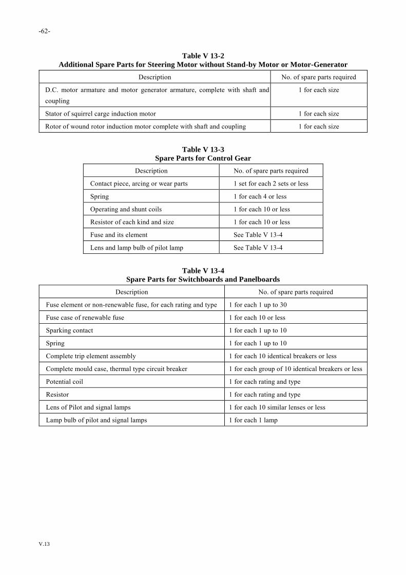
-62-
V.13
Table V 13-2
Additional Spare Parts for Steering Motor without Stand-by Motor or Motor-Generator
Description No. of spare parts required
D.C. motor armature and motor generator armature, complete with shaft and
coupling
1 for each size
Stator of squirrel carge induction motor 1 for each size
Rotor of wound rotor induction motor complete with shaft and coupling 1 for each size
Table V 13-3
Spare Parts for Control Gear
Description No. of spare parts required
Contact piece, arcing or wear parts 1 set for each 2 sets or less
Spring 1 for each 4 or less
Operating and shunt coils 1 for each 10 or less
Resistor of each kind and size 1 for each 10 or less
Fuse and its element See Table V 13-4
Lens and lamp bulb of pilot lamp See Table V 13-4
Table V 13-4
Spare Parts for Switchboards and Panelboards
Description No. of spare parts required
Fuse element or non-renewable fuse, for each rating and type 1 for each 1 up to 30
Fuse case of renewable fuse 1 for each 10 or less
Sparking contact 1 for each 1 up to 10
Spring 1 for each 1 up to 10
Complete trip element assembly 1 for each 10 identical breakers or less
Complete mould case, thermal type circuit breaker 1 for each group of 10 identical breakers or less
Potential coil 1 for each rating and type
Resistor 1 for each rating and type
Lens of Pilot and signal lamps 1 for each 10 similar lenses or less
Lamp bulb of pilot and signal lamps 1 for each 1 lamp


Tel: +886 2 25062711
Fax: +886 2 25074722
E-mail: [email protected]
Website: http://www.crclass.org
© CR – All rights reserved