RSD-20 - isurplus.com.au RSD20 User Manual.pdf · RSD-20 High Speed Digital Sharing Device...
29
RSD-20 High Speed Digital Sharing Device Installation and Operation Manual Notice This manual contains information that is proprietary to RAD Data Communications. No part of this publication may be reproduced in any form whatsoever without prior written approval by RAD Data Communications. No representation or warranties for fitness for any purpose other than what is specifically mentioned in this manual is made either by RAD Data Communications or its agents. For further information contact RAD Data Communications at the address below or contact your local distributor. RAD data communications Headquarters 12 Hanechoshet Street Tel Aviv 69710 Israel Tel: 972-3-6458181 Fax: 972-3-6498250 E-mail: [email protected] RAD data communications US East 900 Corporate Drive Mahwah, NJ 07430 USA Tel: (201) 529-1100 Fax: (201) 529-5777 E-mail: [email protected] RAD data communications US West 3631 South Harbor Boulevard Suite 250 Santa Ana, CA 92704 Tel: (714) 850-0555 Fax: (714) 850-1555 © 1999 RAD Data Communications Publication No. 544-200-11/99
Transcript of RSD-20 - isurplus.com.au RSD20 User Manual.pdf · RSD-20 High Speed Digital Sharing Device...
RSD-20High Speed Digital Sharing Device
Installation and Operation Manual
Notice
This manual contains information that is proprietary to RAD Data Communications. No part of thispublication may be reproduced in any form whatsoever without prior written approval by RADData Communications.
No representation or warranties for fitness for any purpose other than what is specificallymentioned in this manual is made either by RAD Data Communications or its agents.
For further information contact RAD Data Communications at the address below or contact yourlocal distributor.
RAD data communicationsHeadquarters12 Hanechoshet StreetTel Aviv 69710 IsraelTel: 972-3-6458181Fax: 972-3-6498250E-mail: [email protected]
RAD data communicationsUS East900 Corporate DriveMahwah, NJ 07430 USATel: (201) 529-1100Fax: (201) 529-5777E-mail: [email protected]
RAD data communicationsUS West3631 South HarborBoulevardSuite 250Santa Ana, CA 92704Tel: (714) 850-0555Fax: (714) 850-1555
© 1999 RAD Data Communications Publication No. 544-200-11/99
��������
����������� ������������������������������������������������������������������������������������������������� ���������������������������������������������������������������� �������������������������������������������������������������� ���� �������� �������������������������������������������� ��������������������������������������������������������������������� �������� ������� ���� �������� �������������������������������� ����������!�������� ������ ������������������������ ����
�������������������
����������������������������������������������� ����������������������" ������������������� ����� ��#� �������������������������� �� ����$��������������������� ������������ ������������������������������������������������� �������������������������������������
����������������
��������������������������������� ��%������������!�� ��������������������������������������������������������������������������������������" ���������������������������������������������������������������
������������������
��������������������
������" ���������������������������� �����������������������������������&���������������������� � �������'���()���������&&� ��������������������������������������������������������������������� �����������������������" ������������������������������������������������" ���������������� ��������������������������" ������������������������������������� ����������������������������� ��������� ���������� ������� ����������������������������� ����������*����������������" ����������������������������������������� ������� ������������������������������ ������������" ����������������������������������������!�����
������������ ���!""
����� ��� ��&��������� ���� +������������������������� ������� ��������� ��� ����� ������������ ����������������� �����������" ���������������" �������� ���

#��������������
�����!������������������������������������������������������������������������������������������������������������������������������� �������������������������������������� ������������������$���
�������������������������������� ������� ��������������������������������������������������� ����*������" ������������� ����$��������������������� �������� ����, �������������������������������������� ������-����, ������������������������������ ������������������������������������� ���
��������������� ����������.�#(/��������.012�3��������!��������������4�
$�������������������
Manufacturer’s Name: RAD Data Communications Ltd.
Manufacturer’s Address: 12 Hanechoshet St.Tel Aviv 69710Israel
declares that the product:
Product Name: RSD-10
Conforms to the following standard(s) or other normative document(s):
EMC: EN 55022 (1994) Limits and methods of measurement of radio disturbancecharacteristics of information technology equipment.
EN 50082-1 (1992) Electromagnetic compatibility - Generic immunitystandards for residential, commercial and light industry.
Safety: EN 60950 (1992/93) Safety of information technology equipment, includingelectrical business equipment.
Supplementary Information:
The product herewith complies with the requirements of the EMC Directive 89/336/EEC and theLow Voltage Directive 73/23/EEC. The product was tested in a typical configuration.
Tel Aviv, October 7th, 1996
Haim KarshenVP Quality
European Contact: RAD Data Communications GmbH, Lyoner Strasse 14, 60528 Frankfurt am Main, Germany
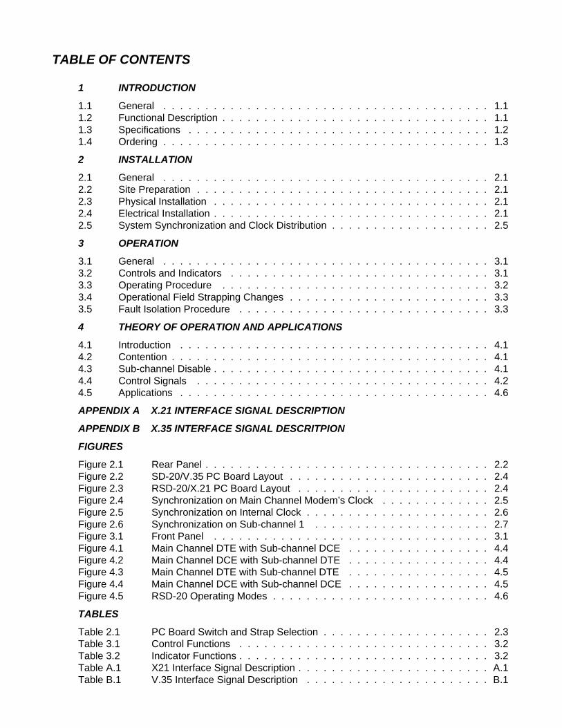
TABLE OF CONTENTS
1 INTRODUCTION
1.1 General . . . . . . . . . . . . . . . . . . . . . . . . . . . . . . . . . . . . . . . 1.11.2 Functional Description . . . . . . . . . . . . . . . . . . . . . . . . . . . . . . . . 1.11.3 Specifications . . . . . . . . . . . . . . . . . . . . . . . . . . . . . . . . . . . . 1.21.4 Ordering . . . . . . . . . . . . . . . . . . . . . . . . . . . . . . . . . . . . . . . 1.3
2 INSTALLATION
2.1 General . . . . . . . . . . . . . . . . . . . . . . . . . . . . . . . . . . . . . . . 2.12.2 Site Preparation . . . . . . . . . . . . . . . . . . . . . . . . . . . . . . . . . . . 2.12.3 Physical Installation . . . . . . . . . . . . . . . . . . . . . . . . . . . . . . . . . 2.12.4 Electrical Installation . . . . . . . . . . . . . . . . . . . . . . . . . . . . . . . . . 2.12.5 System Synchronization and Clock Distribution . . . . . . . . . . . . . . . . . . . 2.5
3 OPERATION
3.1 General . . . . . . . . . . . . . . . . . . . . . . . . . . . . . . . . . . . . . . . 3.13.2 Controls and Indicators . . . . . . . . . . . . . . . . . . . . . . . . . . . . . . . 3.13.3 Operating Procedure . . . . . . . . . . . . . . . . . . . . . . . . . . . . . . . . 3.23.4 Operational Field Strapping Changes . . . . . . . . . . . . . . . . . . . . . . . . 3.33.5 Fault Isolation Procedure . . . . . . . . . . . . . . . . . . . . . . . . . . . . . . 3.3
4 THEORY OF OPERATION AND APPLICATIONS
4.1 Introduction . . . . . . . . . . . . . . . . . . . . . . . . . . . . . . . . . . . . . 4.14.2 Contention . . . . . . . . . . . . . . . . . . . . . . . . . . . . . . . . . . . . . . 4.14.3 Sub-channel Disable . . . . . . . . . . . . . . . . . . . . . . . . . . . . . . . . . 4.14.4 Control Signals . . . . . . . . . . . . . . . . . . . . . . . . . . . . . . . . . . . 4.24.5 Applications . . . . . . . . . . . . . . . . . . . . . . . . . . . . . . . . . . . . . 4.6
APPENDIX A X.21 INTERFACE SIGNAL DESCRIPTION
APPENDIX B X.35 INTERFACE SIGNAL DESCRITPION
FIGURES
Figure 2.1 Rear Panel . . . . . . . . . . . . . . . . . . . . . . . . . . . . . . . . . . 2.2Figure 2.2 SD-20/V.35 PC Board Layout . . . . . . . . . . . . . . . . . . . . . . . . 2.4Figure 2.3 RSD-20/X.21 PC Board Layout . . . . . . . . . . . . . . . . . . . . . . . 2.4Figure 2.4 Synchronization on Main Channel Modem’s Clock . . . . . . . . . . . . . 2.5Figure 2.5 Synchronization on Internal Clock . . . . . . . . . . . . . . . . . . . . . . 2.6Figure 2.6 Synchronization on Sub-channel 1 . . . . . . . . . . . . . . . . . . . . . 2.7Figure 3.1 Front Panel . . . . . . . . . . . . . . . . . . . . . . . . . . . . . . . . . 3.1Figure 4.1 Main Channel DTE with Sub-channel DCE . . . . . . . . . . . . . . . . . 4.4Figure 4.2 Main Channel DCE with Sub-channel DTE . . . . . . . . . . . . . . . . . 4.4Figure 4.3 Main Channel DTE with Sub-channel DTE . . . . . . . . . . . . . . . . . 4.5Figure 4.4 Main Channel DCE with Sub-channel DCE . . . . . . . . . . . . . . . . . 4.5Figure 4.5 RSD-20 Operating Modes . . . . . . . . . . . . . . . . . . . . . . . . . . 4.6
TABLES
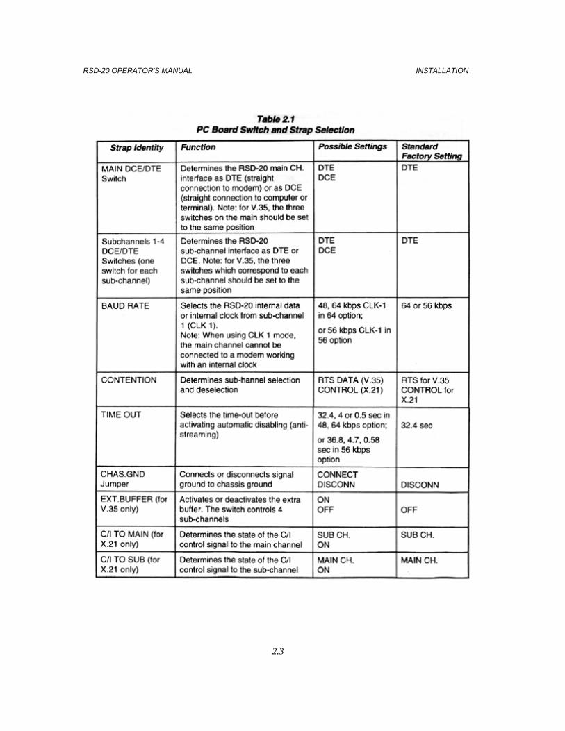
Table 2.1 PC Board Switch and Strap Selection . . . . . . . . . . . . . . . . . . . . 2.3Table 3.1 Control Functions . . . . . . . . . . . . . . . . . . . . . . . . . . . . . . 3.2Table 3.2 Indicator Functions . . . . . . . . . . . . . . . . . . . . . . . . . . . . . . 3.2Table A.1 X21 Interface Signal Description . . . . . . . . . . . . . . . . . . . . . . . A.1Table B.1 V.35 Interface Signal Description . . . . . . . . . . . . . . . . . . . . . . B.1
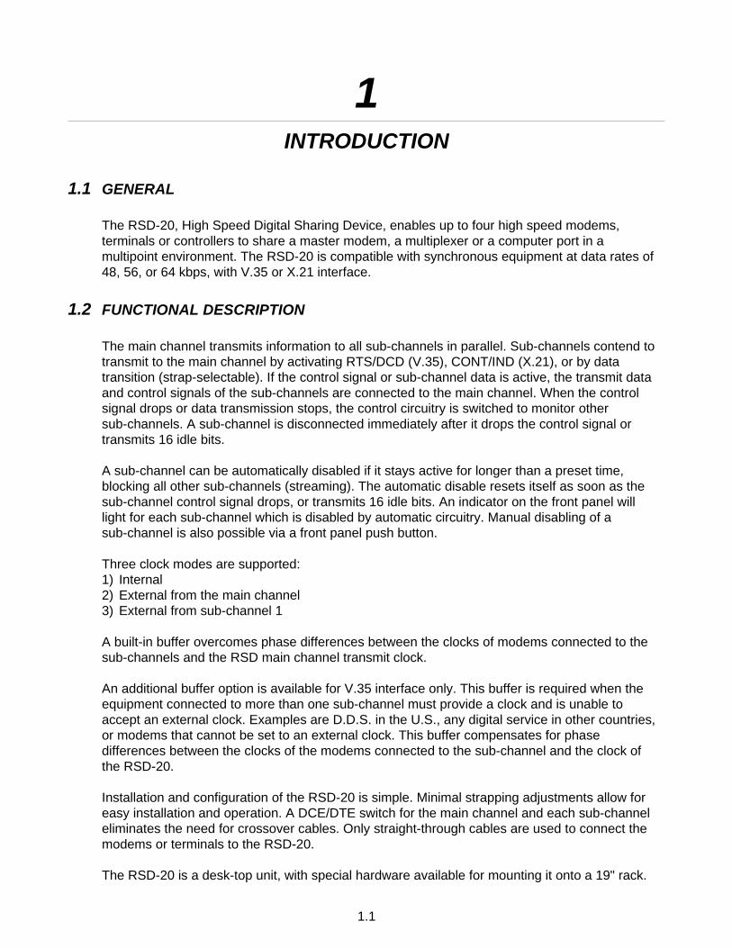
1INTRODUCTION
1.1 GENERAL
The RSD-20, High Speed Digital Sharing Device, enables up to four high speed modems,terminals or controllers to share a master modem, a multiplexer or a computer port in amultipoint environment. The RSD-20 is compatible with synchronous equipment at data rates of48, 56, or 64 kbps, with V.35 or X.21 interface.
1.2 FUNCTIONAL DESCRIPTION
The main channel transmits information to all sub-channels in parallel. Sub-channels contend totransmit to the main channel by activating RTS/DCD (V.35), CONT/IND (X.21), or by datatransition (strap-selectable). If the control signal or sub-channel data is active, the transmit dataand control signals of the sub-channels are connected to the main channel. When the controlsignal drops or data transmission stops, the control circuitry is switched to monitor othersub-channels. A sub-channel is disconnected immediately after it drops the control signal ortransmits 16 idle bits.
A sub-channel can be automatically disabled if it stays active for longer than a preset time,blocking all other sub-channels (streaming). The automatic disable resets itself as soon as thesub-channel control signal drops, or transmits 16 idle bits. An indicator on the front panel willlight for each sub-channel which is disabled by automatic circuitry. Manual disabling of asub-channel is also possible via a front panel push button.
Three clock modes are supported:1) Internal2) External from the main channel3) External from sub-channel 1
A built-in buffer overcomes phase differences between the clocks of modems connected to thesub-channels and the RSD main channel transmit clock.
An additional buffer option is available for V.35 interface only. This buffer is required when theequipment connected to more than one sub-channel must provide a clock and is unable toaccept an external clock. Examples are D.D.S. in the U.S., any digital service in other countries,or modems that cannot be set to an external clock. This buffer compensates for phasedifferences between the clocks of the modems connected to the sub-channel and the clock ofthe RSD-20.
Installation and configuration of the RSD-20 is simple. Minimal strapping adjustments allow foreasy installation and operation. A DCE/DTE switch for the main channel and each sub-channeleliminates the need for crossover cables. Only straight-through cables are used to connect themodems or terminals to the RSD-20.
The RSD-20 is a desk-top unit, with special hardware available for mounting it onto a 19" rack.
1.1

1.3 SPECIFICATIONS
Number of Sub-channels
Four
Channel Configuration
Lowest priority: Sub-channel 1Highest priority: Sub-channel 4
Sub-channel Selection
Strap-selectable to:Control signal RTS/DCD (V.35) or CONT/IND (X.21) ONData transitions
Sub-channel Deselection
RTS/DCD (V.35) or CONT/IND (X.21) OFF (in control contention)16 bits of idle data (in data contention)
Sub-channel Disabling
Manual: Via front panel switchesAutomatic: If sub-channel stays connected for more than a pre-set time period
(32.4, 4, 0.5 sec for 64 or 48 kbps; 36.8, 4.7 or 0.6 for 56 kbps)
Transmit Clock Source
– Internal– External derived from main channel– External derived from sub-channel 1
Data Rates
Synchronous:Internal Clock:– Selectable 48, 64 kbps for 64 kbps option– 56 kbpsExternal Clock:– Derived from main channel (modem in internal mode)– Derived from sub-channel 1 (up to 128 kbps)
Input and Output Interface
V.35 or X.21
Connectors
– Five 34-pin V.35, female,– Five DB-15 X.21, female
Controls
Four manual sub-channel DISABLE switches, one per sub-channel;Push-button switches
RSD-20 OPERATOR'S MANUAL INTRODUCTION
1.2

Indicators
DATA: Display data broadcast from main channel to sub-channelsACTIVITY: 4 LEDs indicate which sub-channel has gained access to main channelDISABLE: 4 LEDs indicate if sub-channel has been disabled automaticallyON: RSD power is on
Power
115/230 VAC switchable;10%; 47-63 Hz; 10 W
Physical
Height: 44 mm / 1.7 in (1U)Width: 431 mm / 17.0 inDepth: 208 mm / 8.2 inWeight: 2 kg / 4.4 lb
Environment
Temperature: 0-50oC/32-122oFHumidity: Up to 90%, non-condensing
1.4 ORDERING
RSD-20/+/*/#Digital Sharing Device
+ Specify:64 for 64/48 kbps (selectable)56 for 56 kbps
* Specify interface:V.35 for V.35 interfaceX.21 for X.21 interface
INTRODUCTION RSD-20 OPERATOR'S MANUAL
1.3
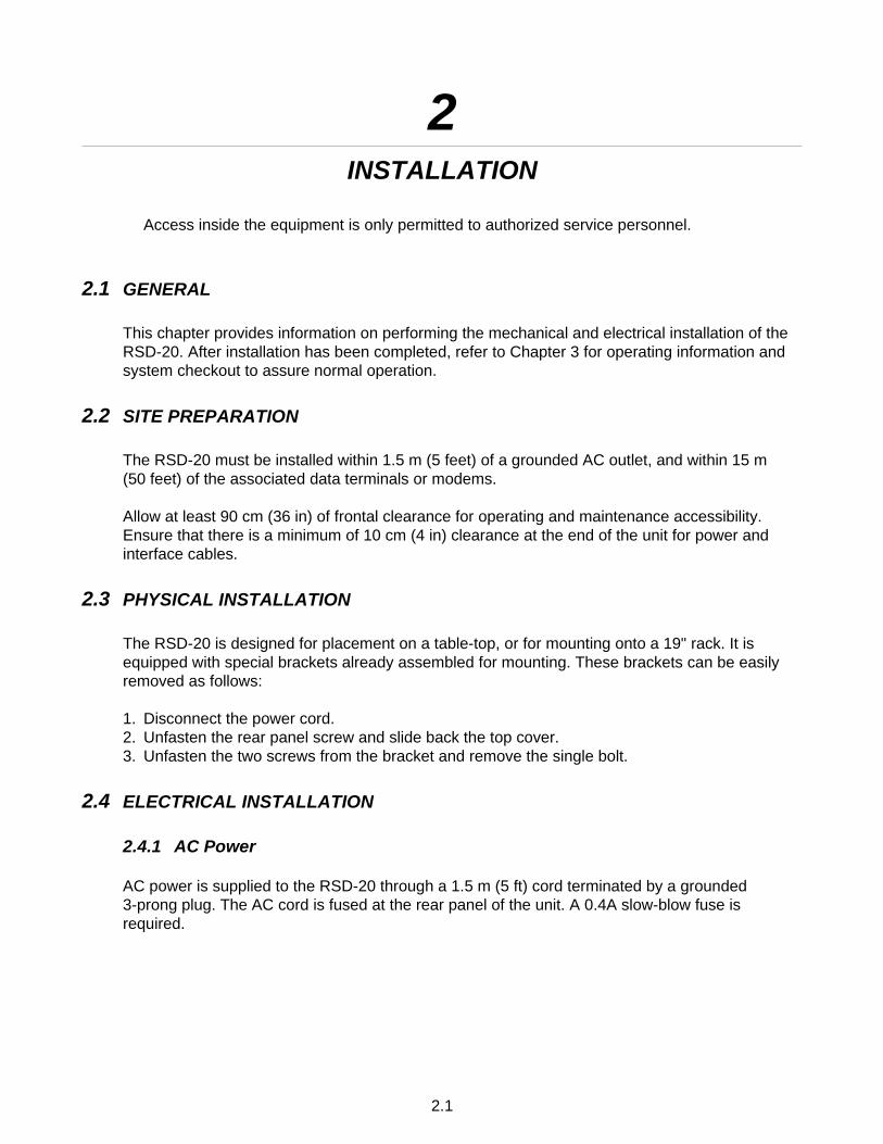
2INSTALLATION
Access inside the equipment is only permitted to authorized service personnel.
2.1 GENERAL
This chapter provides information on performing the mechanical and electrical installation of theRSD-20. After installation has been completed, refer to Chapter 3 for operating information andsystem checkout to assure normal operation.
2.2 SITE PREPARATION
The RSD-20 must be installed within 1.5 m (5 feet) of a grounded AC outlet, and within 15 m(50 feet) of the associated data terminals or modems.
Allow at least 90 cm (36 in) of frontal clearance for operating and maintenance accessibility.Ensure that there is a minimum of 10 cm (4 in) clearance at the end of the unit for power andinterface cables.
2.3 PHYSICAL INSTALLATION
The RSD-20 is designed for placement on a table-top, or for mounting onto a 19" rack. It isequipped with special brackets already assembled for mounting. These brackets can be easilyremoved as follows:
1. Disconnect the power cord.2. Unfasten the rear panel screw and slide back the top cover.3. Unfasten the two screws from the bracket and remove the single bolt.
2.4 ELECTRICAL INSTALLATION
2.4.1 AC Power
AC power is supplied to the RSD-20 through a 1.5 m (5 ft) cord terminated by a grounded3-prong plug. The AC cord is fused at the rear panel of the unit. A 0.4A slow-blow fuse isrequired.
2.1
2.4.2 Rear Panel
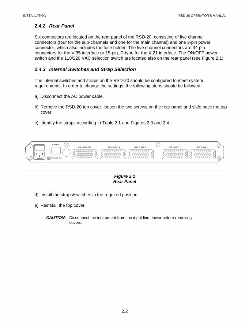
Six connectors are located on the rear panel of the RSD-20, consisting of five channelconnectors (four for the sub-channels and one for the main channel) and one 3-pin powerconnector, which also includes the fuse holder. The five channel connectors are 34-pinconnectors for the V.35 interface or 15-pin, D-type for the X.21 interface. The ON/OFF powerswitch and the 110/220 VAC selection switch are located also on the rear panel (see Figure 2.1).
2.4.3 Internal Switches and Strap Selection
The internal switches and straps on the RSD-20 should be configured to meet systemrequirements. In order to change the settings, the following steps should be followed:
a) Disconnect the AC power cable.
b) Remove the RSD-20 top cover, loosen the two screws on the rear panel and slide back the topcover.
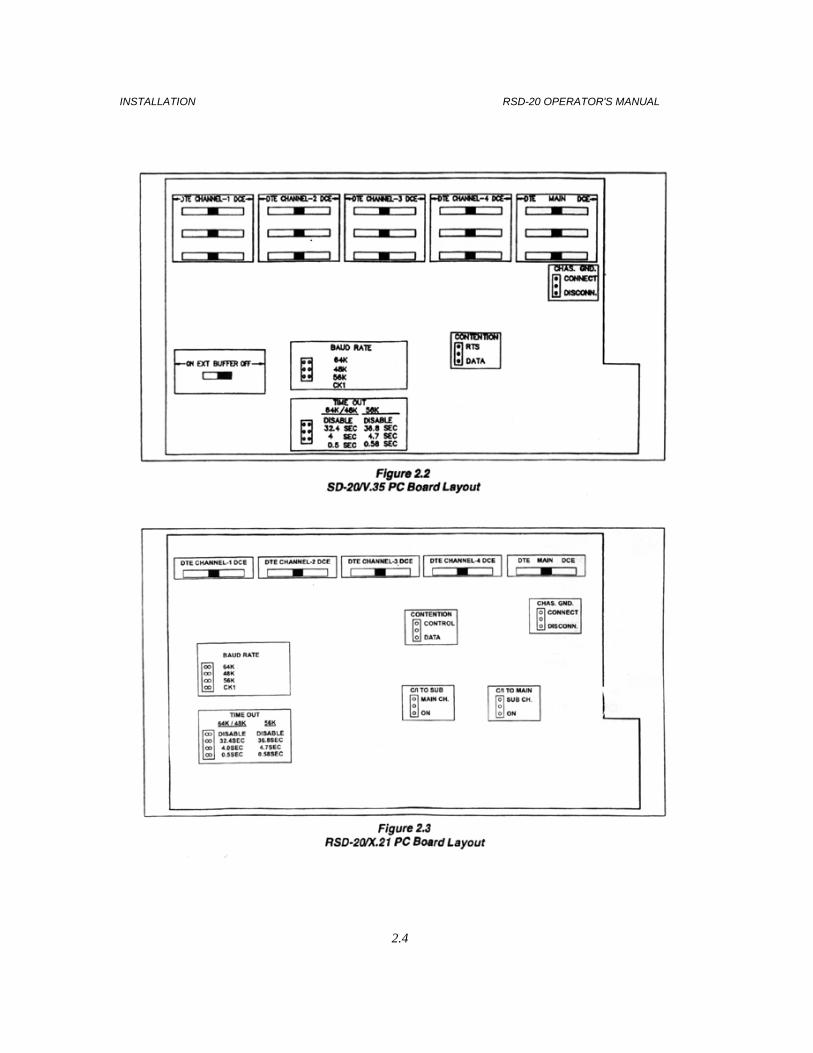
c) Identify the straps according to Table 2.1 and Figures 2.3 and 2.4.
d) Install the straps/switches in the required position.
e) Reinstall the top cover.
CAUTION Disconnect the instrument from the input line power before removingcovers.
MAIN CHANNEL SUB CHAN. 1SUB CHAN. 2SUB CHAN. 3SUB CHAN. 4
POWER
~230V~115V
F-0.400A S.B.
Figure 2.1Rear Panel
INSTALLATION RSD-20 OPERATOR'S MANUAL
2.2
RSD-20 OPERATOR'S MANUAL INSTALLATION
2.3
INSTALLATION RSD-20 OPERATOR'S MANUAL
2.4
2.5 SYSTEM SYNCHRONIZATION AND CLOCK DISTRIBUTION
2.5.1 RSD-20/V.35
Four alternatives are available for synchronization of the system:a) Main channel modem timing signals.
b) RSD-20 internal clock.c) Sub-channel 1 modem timing signals.d) Any sub-channel modem timing signals. For this the optional buffer is required.
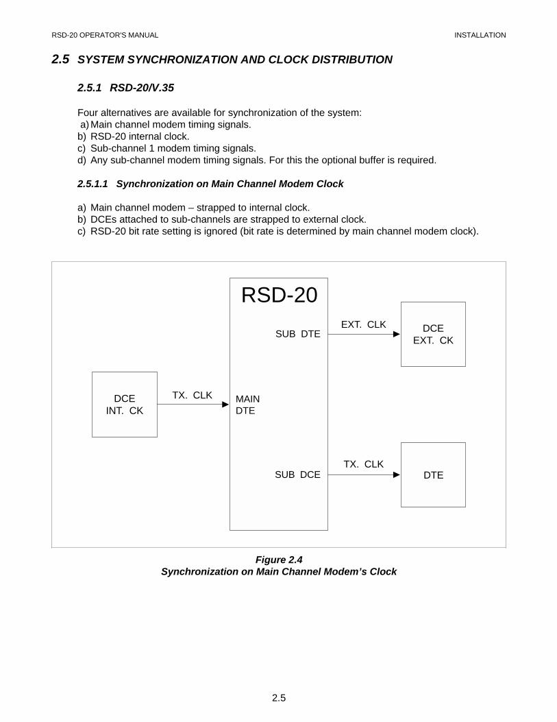
2.5.1.1 Synchronization on Main Channel Modem Clock
a) Main channel modem – strapped to internal clock.b) DCEs attached to sub-channels are strapped to external clock.c) RSD-20 bit rate setting is ignored (bit rate is determined by main channel modem clock).
RSD-20
DCEINT. CK
DCEEXT. CK
DTETX. CLK
TX. CLK
EXT. CLKSUB DTE
MAINDTE
SUB DCE
Figure 2.4Synchronization on Main Channel Modem’s Clock
RSD-20 OPERATOR'S MANUAL INSTALLATION
2.5
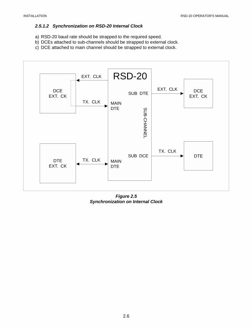
2.5.1.2 Synchronization on RSD-20 Internal Clock
a) RSD-20 baud rate should be strapped to the required speed.b) DCEs attached to sub-channels should be strapped to external clock.c) DCE attached to main channel should be strapped to external clock.
RSD-20DCE
EXT. CK
DTEEXT. CK
DCEEXT. CK
DTETX. CLK
TX. CLK
TX. CLK
EXT. CLK
EXT. CLKSUB DTE
MAINDTE
MAINDTE
SUB DCE
SU
B-C
HA
NN
EL
Figure 2.5Synchronization on Internal Clock
INSTALLATION RSD-20 OPERATOR'S MANUAL
2.6
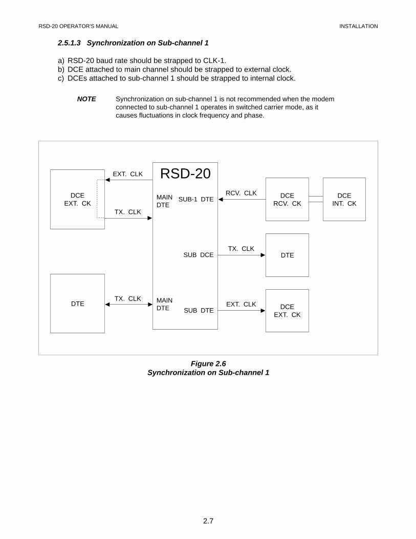
2.5.1.3 Synchronization on Sub-channel 1
a) RSD-20 baud rate should be strapped to CLK-1.b) DCE attached to main channel should be strapped to external clock.c) DCEs attached to sub-channel 1 should be strapped to internal clock.
NOTE Synchronization on sub-channel 1 is not recommended when the modemconnected to sub-channel 1 operates in switched carrier mode, as itcauses fluctuations in clock frequency and phase.
RSD-20DCE
EXT. CKDCE
RCV. CKDCE
INT. CK
DTE
DTE DCEEXT. CK
TX. CLK
TX. CLK
EXT. CLK
RCV. CLK
TX. CLK
EXT. CLK
SUB-1 DTE
SUB DCE
SUB DTE
MAINDTE
MAINDTE
Figure 2.6Synchronization on Sub-channel 1
RSD-20 OPERATOR'S MANUAL INSTALLATION
2.7
2.5.1.4 External Clock for more than one Sub-channel
This option enables connection of more than one sub-channel to the line from the P.T.T. service.Generally, the P.T.T. modems supply clock to every line – i.e. the P.T.T. has to provide theclock. Since the modems are all from the same service, the clocks are synchronized. Theexternal buffer will compensate for phase differences between the clocks received from thesub-channels. However, the external buffer option will not compensate for the clock differences,if different clock sources are used.
2.5.2 RSD-20/X.21
The X.21 standard states that DCEs and DTEs will only have one clock signal (signal timing).The direction of this clock is always from the DCE to DTE. This signal timing is used for thetransmit clock and receive clock.
According to this standard, four alternatives are available for the synchronization of the systemwhen working with the RSD-20/X.21:a) Main channel is DTE (attached to a modem).b) Main and all sub-channels are DCE (attached to DTEs).
c) Main channel is DCE (attached to a DTE and all sub-channels are DTE (attached to modems).d) Main channel is DCE and sub-channels are mixed (DTEs and DCEs).
2.5.2.1 Main channel is DTE(attached to a modem)
In this mode the RSD operates according to the signal timing of clock of the main channelmodem. DTEs attached to the RSD-20 sub-channels are synchronized to the mains clock.
DCEs attached to sub-channels are synchronized on their own signal timing. A special buffer,integrated in the RSD-20/X.21, compensates for the phase difference between the modems ofthe sub-channels and the main channel modem.
2.5.2.2 Main and all sub-channels are DCE(attached to DTEs)
In this mode the RSD provides the clock to all ports attached to the main and sub-channels. TheRSD’s baud rate should be strapped to the appropriate system baud rate.
2.5.2.3 Main channel is DCE (attached to a DTE) and all sub-channels are DTE(attached to modems)
In this mode the RSD’s baud rate is strapped to CLK-1. The DTE attached to the main channelis synchronized to the RSD’s clock, the modems attached to sub-channels 2, 3, 4 should bestrapped to external clock, except for the modem attached to sub-channel 1 which should bestrapped to internal clock.
NOTE It is also possible to work with the RSD’s internal clock in this mode, butCLK-1 is preferred.
INSTALLATION RSD-20 OPERATOR'S MANUAL
2.8
2.5.2.4 Main channel is DCE and sub-channels are mixed(DTE and DCE)
In this mode one of the modems attached to the sub-channels (configured as DTE) should beattached to sub-channel 1, and the RSD baud rate should be strapped to CLK-1.
The DTEs attached to the main and sub-channels are synchronized to the RSD’s clock; themodems attached to the sub-channels are synchronized to their own clock; and the internalbuffer compensates for the phase difference between the signal timing of the modem attached tosub-channel 1 to the rest of the modems.
NOTE 1. Working with RSD’s internal clock is also possible but CLK-1 ispreferred.
2. On DTE (sub-channels 1 to 4 and Main channel), the RSD-20 suppliesclock on pins 7 and 14 for DCE external clock (The DCE must supportexternal clock as in the ASM-20/8-X.21).
WARNING Before plugging in this unit, the protective ground (earth) terminals mustbe connected to the protective conductor of the (mains) power cord. Themains plug should only be inserted in a socket outlet provided with aprotective ground (earth) contact. The protective action must not benegated by use of an extension cord (power cable) without a protectiveconductor (grounding).
Ensure that only fuses with the required rated current, and specified type(slow blow, 0.4A) are used for replacement. The use of repaired fuses,and the short-circuiting of fuse holders is strictly forbidden.
Whenever it is likely that the protection offered by fuses has beenimpaired, the instrument must be made inoperative and secured againstunintended operation.
With the unit power turned on, operating personnel are not exposed tovoltages in excess of 30 volts on any I/O pin, provided that the equipmentto which the RSD-20 is connected is safe.
RSD-20 OPERATOR'S MANUAL INSTALLATION
2.9
3OPERATION
3.1 GENERAL
This chapter details the RSD-20 controls and indicators, their functions, and operatingprocedures.
The installation procedures given in Chapter 2 must be completed and checked before operationof the RSD-20 is attempted.
NOTE For an explanation of all the possible system installations of the RSD-20,refer to Chapter 4.
3.2 CONTROLS AND INDICATORS
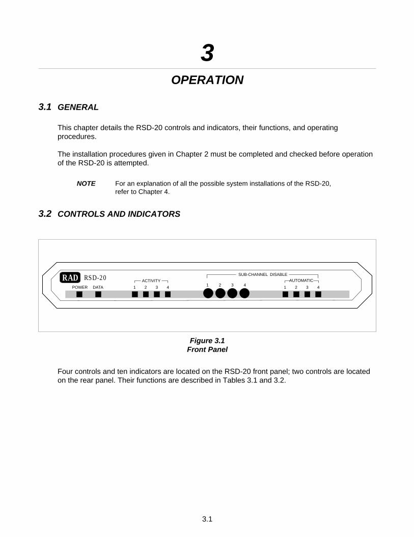
Four controls and ten indicators are located on the RSD-20 front panel; two controls are locatedon the rear panel. Their functions are described in Tables 3.1 and 3.2.
RAD RSD-20POWER DATA 1 2 3 4 1 2 3 4 1 2 3 4
ACTIVITY AUTOMATICSUB-CHANNEL DISABLE
Figure 3.1Front Panel
3.1
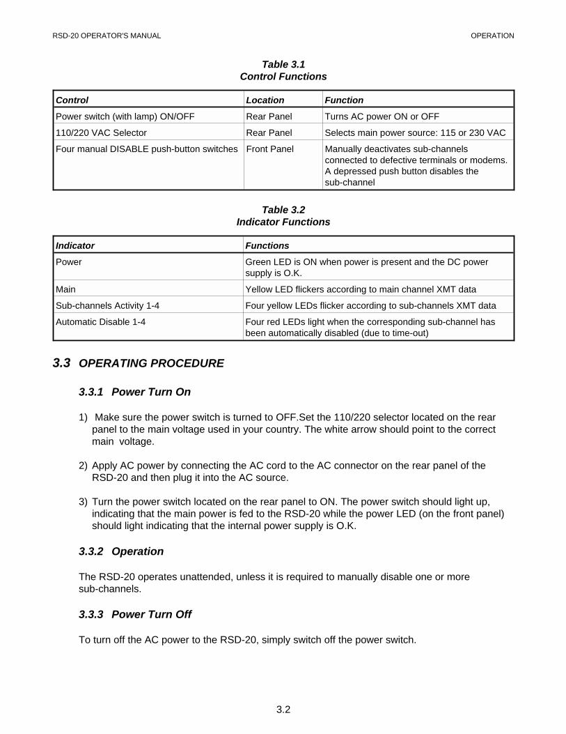
Table 3.1Control Functions
Control Location Function
Power switch (with lamp) ON/OFF Rear Panel Turns AC power ON or OFF
110/220 VAC Selector Rear Panel Selects main power source: 115 or 230 VAC
Four manual DISABLE push-button switches Front Panel Manually deactivates sub-channelsconnected to defective terminals or modems.A depressed push button disables thesub-channel
Table 3.2Indicator Functions
Indicator Functions
Power Green LED is ON when power is present and the DC powersupply is O.K.
Main Yellow LED flickers according to main channel XMT data
Sub-channels Activity 1-4 Four yellow LEDs flicker according to sub-channels XMT data
Automatic Disable 1-4 Four red LEDs light when the corresponding sub-channel hasbeen automatically disabled (due to time-out)
3.3 OPERATING PROCEDURE
3.3.1 Power Turn On
1) Make sure the power switch is turned to OFF.Set the 110/220 selector located on the rearpanel to the main voltage used in your country. The white arrow should point to the correctmain voltage.
2) Apply AC power by connecting the AC cord to the AC connector on the rear panel of theRSD-20 and then plug it into the AC source.
3) Turn the power switch located on the rear panel to ON. The power switch should light up,indicating that the main power is fed to the RSD-20 while the power LED (on the front panel)should light indicating that the internal power supply is O.K.
3.3.2 Operation
The RSD-20 operates unattended, unless it is required to manually disable one or moresub-channels.
3.3.3 Power Turn Off
To turn off the AC power to the RSD-20, simply switch off the power switch.
RSD-20 OPERATOR'S MANUAL OPERATION
3.2
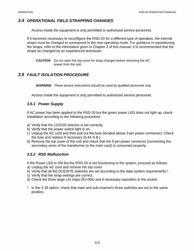
3.4 OPERATIONAL FIELD STRAPPING CHANGES
Access inside the equipment is only permitted to authorized service personnel.
If it becomes necessary to reconfigure the RSD-20 for a different type of operation, the internalstraps must be changed to correspond to the new operating mode. For guidance in repositioningthe straps, refer to the information given in Chapter 2 of this manual. It is recommended that thestraps be changed by an experienced technician.
CAUTION Do not open the top cover for strap changes before removing the ACpower from the unit.
3.5 FAULT ISOLATION PROCEDURE
WARNING These service instructions should be used by qualified personnel only.
Access inside the equipment is only permitted to authorized service personnel.
3.5.1 Power Supply
If AC power has been applied to the RSD-20 but the green power LED does not light up, checkinstallation according to the following procedure:
a) Verify that the 110/220 selector is set correctly.b) Verify that the power switch light is on.c) Unplug the AC cord and then pull out the fuse (located above 3-pin power connector). Check
the fuse and replace if necessary (0.4A S.B.).d) Remove the top cover of the unit and check that the 5-pin power connector (connecting the
secondary wires of the transformer to the main card) is connected properly.
3.5.2 RSD Malfunction
If the Power LED is ON but the RSD-20 is not functioning in the system, proceed as follows:a) Unplug the AC cord and remove the top cover.b) Verify that all the DCE/DTE switches are set according to the data system requirements.*c) Verify that the strap settings are correct.d) Check the three large LSI chips (RJ-006) and if necessary reposition in the socket.
* In the V.35 option, check that main and sub-channel’s three switches are set to the sameposition.
OPERATION RSD-20 OPERATOR'S MANUAL
3.3

4THEORY OF OPERATION AND APPLICATIONS
4.1 INTRODUCTION
This chapter contains a simplified functional description of the RSD-20, and covers the flow ofdata, controls and clocks in all RSD-20 operating modes.
4.2 CONTENTION
RTS/DCD contention in V.35 interface is interchangeable with CONTROL/INDICATIONcontention for X.21 interface. Sub-channel access to the main channel for data transmission iscontrolled by RTS/DCD (Request to Send/Data Carrier Detect) or (CONTROL/INDICATION inX.21 version) or data contention. When selected, the data and timing signals of the activesub-channels pass through the contention circuit and the SELECT/DESELECT circuit of thesub-channels to the elastic buffer, where data is clocked in and out of the main channel.
When a continuous mark is detected, and if strapped to data contention, theSELECT/DESELECT circuit breaks the data path of the active sub-channel. It then selectsanother sub-channel and resets the buffer. Otherwise the sub-channel will remain connecteduntil RTS/DCD or (CONTROL/INDICATION) go down.
4.3 SUB-CHANNEL DISABLE
Manual or automatic disable of streaming sub-channels is possible. If the sub-channel is DTE(connected to a modem) the RSD-20 drops RTS, and if the sub-channel is DCE (connected toport) the RSD-20 drops DCD and CTS and X.21 drops CONT. In addition, the RSD-20 will stoptransmitting data to the sub-channel, and will ignore any data received from it.
4.3.1 Manual Disable
Manual disable is activated by four push-button switches, one for each sub-channel, which arelocated on the front panel. Disabling the sub-channel is achieved by depressing the appropriateswitch. The sub-channel will remain inactive until the switch is released by depressing it again.
4.3.2 Automatic Disable
A streaming sub-channel is disabled automatically if it has stayed active for longer than a presetperiod of time, thereby blocking all other sub-channels. Automatic disabling of a sub-channelresets itself each time RTS/DCD or data (in data contention mode) drops. Selection of one ofthree different time delays or non-active mode as indicated on the PCB.
RSD-20 OPERATOR'S MANUAL THEORY OF OPERATION AND APPLICATIONS
4.4
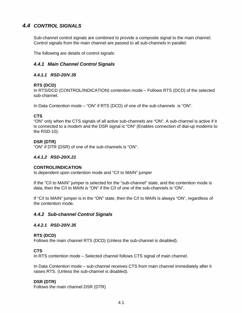
4.4 CONTROL SIGNALS
Sub-channel control signals are combined to provide a composite signal to the main channel.Control signals from the main channel are passed to all sub-channels in parallel.
The following are details of control signals:
4.4.1 Main Channel Control Signals
4.4.1.1 RSD-20/V.35
RTS (DCD)In RTS/DCD (CONTROL/INDICATION) contention mode – Follows RTS (DCD) of the selectedsub-channel.
In Data Contention mode – “ON” if RTS (DCD) of one of the sub-channels is “ON”.
CTS“ON” only when the CTS signals of all active sub-channels are “ON”. A sub-channel is active if itis connected to a modem and the DSR signal is “ON” (Enables connection of dial-up modems tothe RSD-10).
DSR (DTR)“ON” if DTR (DSR) of one of the sub-channels is “ON”.
4.4.1.2 RSD-20/X.21
CONTROL/INDICATIONIs dependent upon contention mode and “C/I to MAIN” jumper
If the “C/I to MAIN” jumper is selected for the “sub-channel” state, and the contention mode isdata, then the C/I to MAIN is “ON” if the C/I of one of the sub-channels is “ON”.
If “C/I to MAIN” jumper is in the “ON” state, then the C/I to MAIN is always “ON”, regardless ofthe contention mode.
4.4.2 Sub-channel Control Signals
4.4.2.1 RSD-20/V.35
RTS (DCD)Follows the main channel RTS (DCD) (Unless the sub-channel is disabled).
CTSIn RTS contention mode – Selected channel follows CTS signal of main channel.
In Data Contention mode – sub-channel receives CTS from main channel immediately after itraises RTS. (Unless the sub-channel is disabled).
DSR (DTR)Follows the main channel DSR (DTR)
4.1
4.4.2.2 RSD-20/X.21
CONTROL/INDICATIONIf the “C/I to Sub-channel” jumper is in the “MAIN CHANNEL” state, the C/I to sub-channelfollows the main C/I (unless the sub-channel is disabled, then the C/I is OFF). If the “C/I tosub-channel is in the ”ON" state, all of the sub-channels’ C/O are “ON” irrespective of the mainchannel C/I.
RSD-20 OPERATOR'S MANUAL THEORY OF OPERATION AND APPLICATIONS
4.2

THEORY OF OPERATION AND APPLICATIONS RSD-20 OPERATOR'S MANUAL
4.3
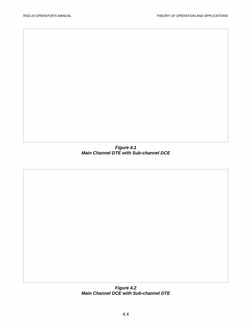
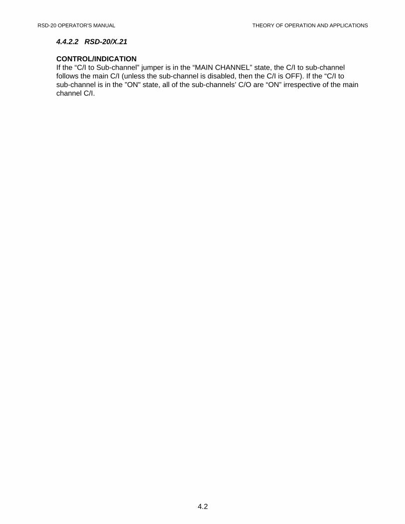
Figure 4.1Main Channel DTE with Sub-channel DCE
Figure 4.2Main Channel DCE with Sub-channel DTE
RSD-20 OPERATOR'S MANUAL THEORY OF OPERATION AND APPLICATIONS
4.4
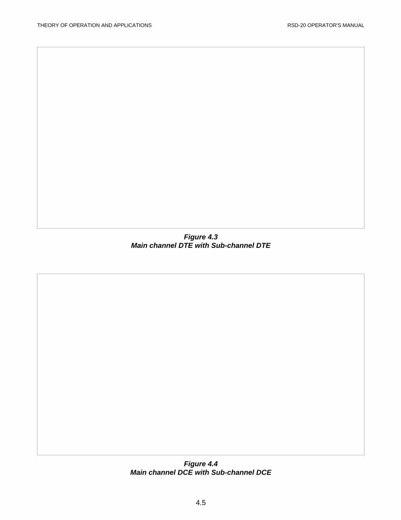
Figure 4.4Main channel DCE with Sub-channel DCE
Figure 4.3Main channel DTE with Sub-channel DTE
THEORY OF OPERATION AND APPLICATIONS RSD-20 OPERATOR'S MANUAL
4.5
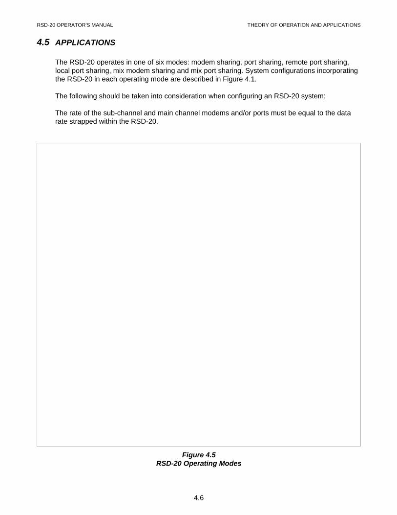
4.5 APPLICATIONS
The RSD-20 operates in one of six modes: modem sharing, port sharing, remote port sharing,local port sharing, mix modem sharing and mix port sharing. System configurations incorporatingthe RSD-20 in each operating mode are described in Figure 4.1.
The following should be taken into consideration when configuring an RSD-20 system:
The rate of the sub-channel and main channel modems and/or ports must be equal to the datarate strapped within the RSD-20.
Figure 4.5RSD-20 Operating Modes
RSD-20 OPERATOR'S MANUAL THEORY OF OPERATION AND APPLICATIONS
4.6
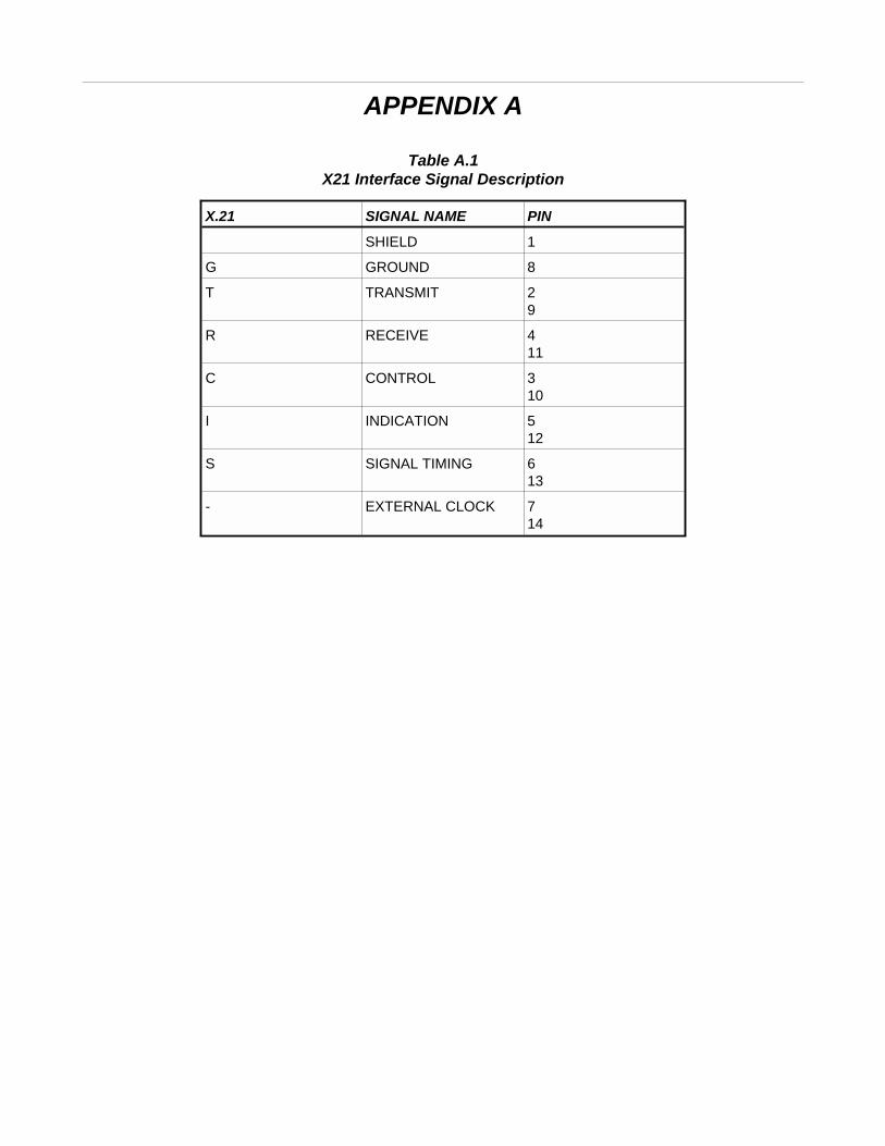
APPENDIX A
Table A.1X21 Interface Signal Description
X.21 SIGNAL NAME PIN
SHIELD 1
G GROUND 8
T TRANSMIT 29
R RECEIVE 411
C CONTROL 310
I INDICATION 512
S SIGNAL TIMING 613
- EXTERNAL CLOCK 714
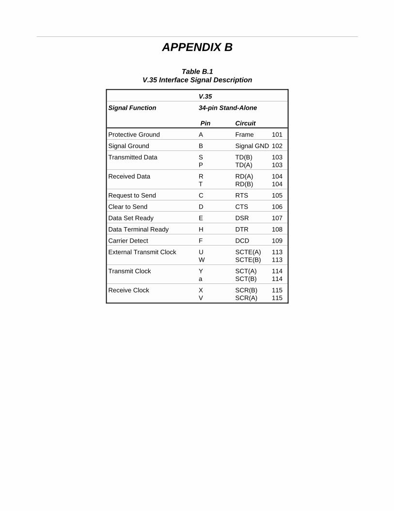
APPENDIX B
Table B.1V.35 Interface Signal Description
V.35
Signal Function 34-pin Stand-Alone
Pin Circuit
Protective Ground A Frame 101
Signal Ground B Signal GND 102
Transmitted Data S TD(B) 103P TD(A) 103
Received Data R RD(A) 104T RD(B) 104
Request to Send C RTS 105
Clear to Send D CTS 106
Data Set Ready E DSR 107
Data Terminal Ready H DTR 108
Carrier Detect F DCD 109
External Transmit Clock U SCTE(A) 113W SCTE(B) 113
Transmit Clock Y SCT(A) 114a SCT(B) 114
Receive Clock X SCR(B) 115V SCR(A) 115