ROLL-FORMED SECTION The process Roll forming is process in which strip or coiled sheet metal is fed...
35
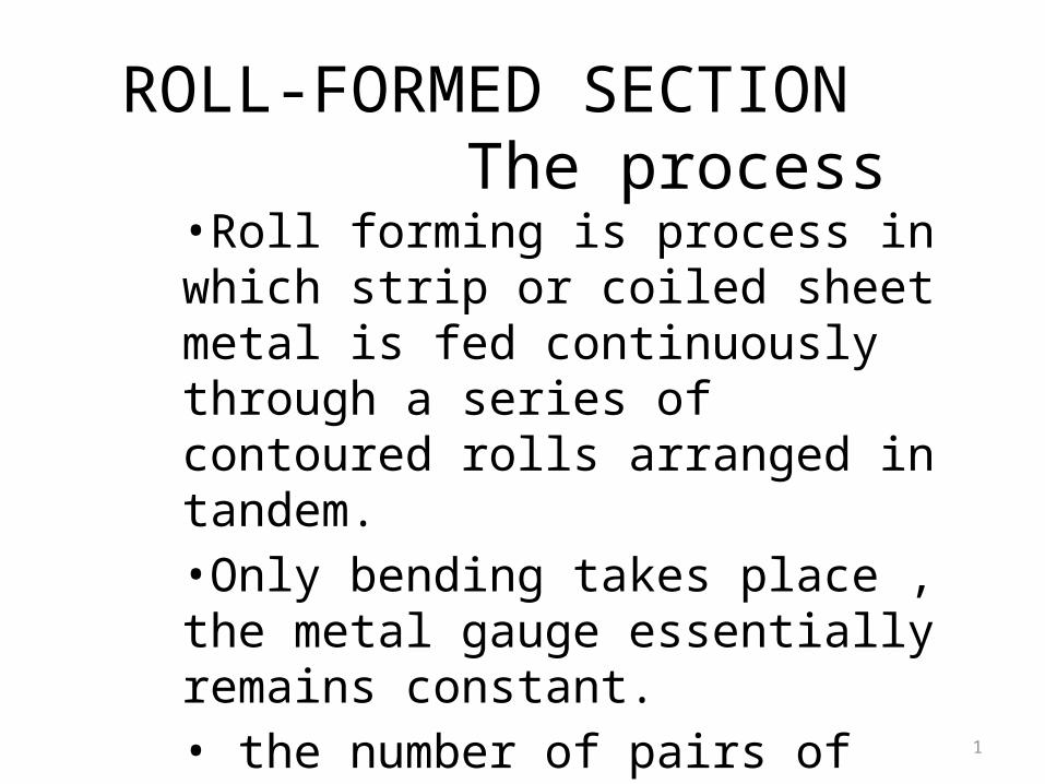
ROLL-FORMED SECTION The process •Roll forming is process in which strip or coiled sheet metal is fed continuously through a series of contoured rolls arranged in tandem. •Only bending takes place , the metal gauge essentially remains constant. • the number of pairs of rolls required to form a 1
-
Upload
salvador-wassell -
Category
Documents
-
view
217 -
download
1
Transcript of ROLL-FORMED SECTION The process Roll forming is process in which strip or coiled sheet metal is fed...
1
ROLL-FORMED SECTION The process
•Roll forming is process in which strip or coiled sheet metal is fed continuously through a series of contoured rolls arranged in tandem.•Only bending takes place , the metal gauge essentially remains constant.• the number of pairs of rolls required to form a particular part depends on :-
2
• Material• Shape to be formed• The precision required
Other operations like notching ,piercing, embossing, welding can be incorporated into the operation.
3
• The most common operation is a “ flying” cutoff operation after operation is completed.
• Punch –press operation are normally located ahead of rolling
4
APPLICATIONS
•Roll forming is a continuous bending operation in which a long strip of metal (typically coiled steel) is passed through consecutive sets of rolls.•Roll forming is ideal for producing parts with long lengths or in large quantities.•A variety of cross-section profiles can be produced, but each profile requires a carefully crafted set of roll tools.•Roll forming can be carried out with plated , galvanised ,lithograped ,vinyl-coated etc…
5
• Dual layered components can also be made at one time.These may include bimetallic parts such as those made when a thin stainless-steel facing sheet and a carbon steel support sheet are formed together.
• Long pieces like railroad-car and truck-trailer trim members can be made with this process.Maximum length of part is dictated only by application requirements and handling conditions.
6
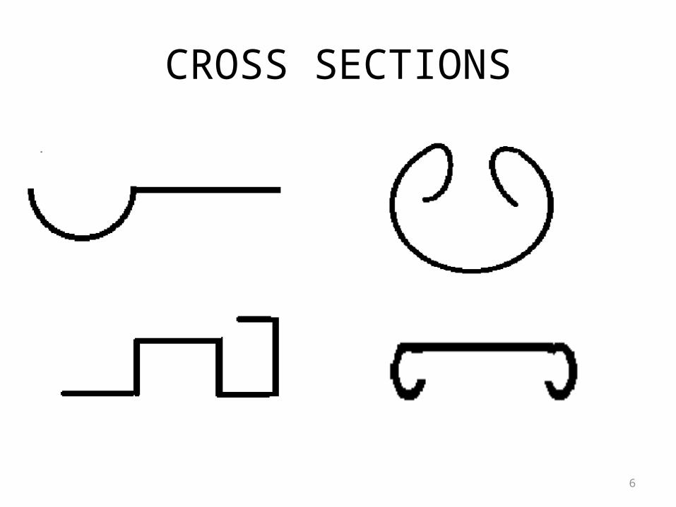
CROSS SECTIONS
7
Typical parts and applications
8
Applications• Roll forming is best applicable for constant complex cross-sectional
shapes.
• Parts often are long length (short part made by cutting strips).
• Possible thickness rolled is 0.13- 25 mm.
commercial limit is 0.25- 4 mm.
width range is 25 mm- 2.5 m.
commercial maximum width is 1 m.
but 400 mm widest stock processible on commonly available machines.
9
applications• Deep forms are difficult (100 mm is practical depth limit).
• Roll formed components are applicable for mass production.
• Building industry – roof and sliding panels, joists, windows frames, downspouts, architectural trim and copper electrical conductors.
• Hot rolling- sheet metals , rail tracks.
• Ring rolling – turbine , pipes, pressure vessels.
10
applications• Appliance parts made by roll forming includes:- panels for
stoves, refrigerators, lighting fixture parts.
• Curtain rods and tracks for sliding doors, drawer handles and metal picture frame members made by rolling.
• Curling (longitudinal bending) can be rolled eg. Bicycle fenders and wheels, barrel hoops, drum rings etc.
11
Assumptions Of Rolling Process
12
• The rolls are straight and rigid cylinders.• The width of the strip is much larger than its
thickness and no significant widening takes place.
• The co-efficient of friction µ is low and constant over the entire roll-job interface.
• The yield stress of the material remains constant for the entire operation , its value being the average of the values at the start and at the end of rolling.
13
• On this assumption,we calculate the following parameter-
a. Torque and power required to drive the rollsb. Roll separating forcec. Power loss in bearing
14
Economic Production Quantities• Roll Forming-Mass Production process
• Production rates are rapid
• Setup and tooling costs high
• For process to be economic at least 100,000ft/yr must be produced
• In some cases 500,000ft/yr is required to make the process justifiable-depending on configuration and efficiency of alternative methods
15
• Set up times are lengthy due to the large number of tooling elements that are interrelated
• Once operative it is an extremely fast process
• Speeds upto 300 ft/min, though average speeds of 50 to 100 ft/min
• Low labour cost
16
• As compared with extrusion or machined parts there is a savings in materials cost
• Overall this contributes to very low cost of production which more than makes up for the high initial setup and tooling costs
17
Material Properties
• All normally formable materials may be used.• Best results with ductile alloys but extreme
ductility is not required.• Deformation parallel to grain lines of the
material prevents fracture.
18
Suitability for Cold Rolling
• Determined by tensile properties• Tensile properties depend on crystal structure• Cold rolling changes crystal structure and
thereby the tensile properties• Material selection should consider change in
properties due to cold working.
19
Elastic Propertiesσ
ε
σ
ε
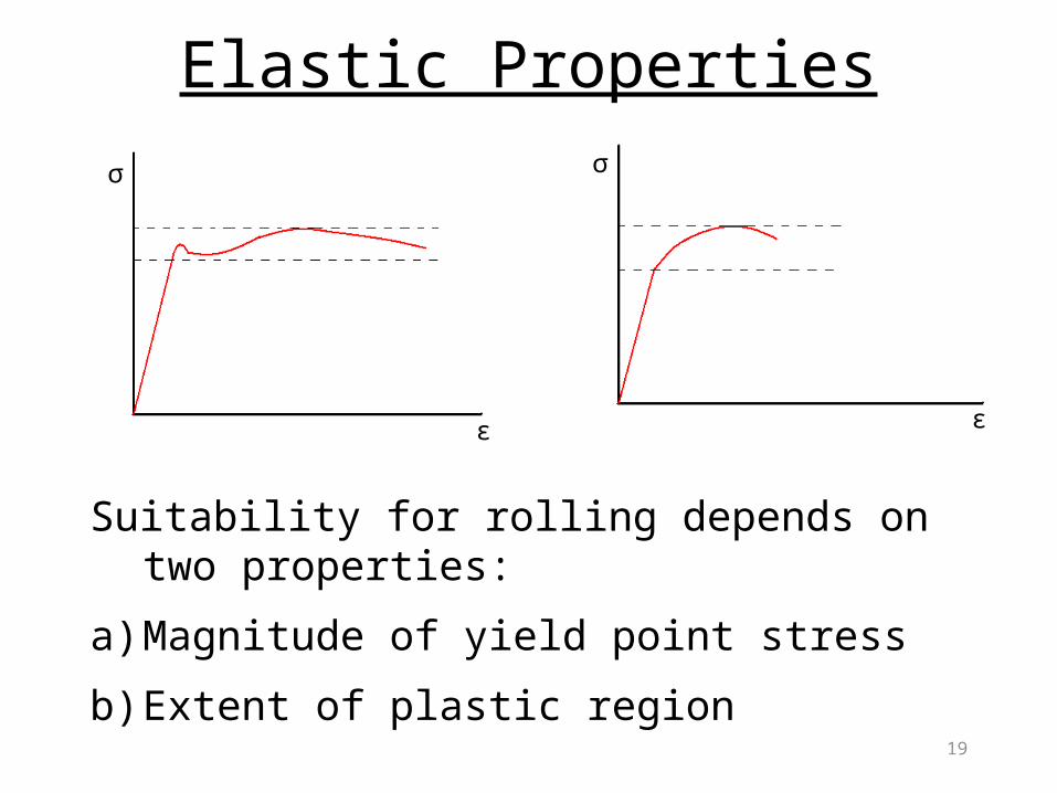
Suitability for rolling depends on two properties:
a) Magnitude of yield point stress
b) Extent of plastic region
20
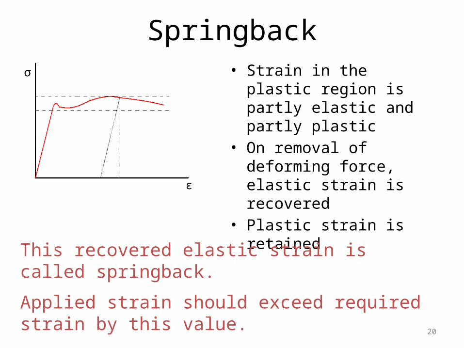
Springback• Strain in the plastic region is
partly elastic and partly plastic• On removal of deforming
force, elastic strain is recovered
• Plastic strain is retained
σ
ε
This recovered elastic strain is called springback.
Applied strain should exceed required strain by this value.
21
Materials Used• Steels – low carbon, stainless, high alloy
steels• Aluminium, Brass, Bronze, Copper• Clad, plated, anodized, galvanized,
organically finished materials• Pre painted stock if coated with durable,
non brittle, baked finish.
22
Design Recommendations
• Parts designer must understand the process thoroughly
• Must be in contact with the engineer who understands the roll forming operation, equipment and tooling i.e. sequence of operations
• High tooling costs, tool wear and forming problems can be reduced by reviewing the sequence of operations.
23
Bending Radii
• Bending radii at both inside and outside corners must be generous- atleast equal to stock thickness or preferably twice stock thickness
• Radii less than one stock thickness possible- sharp bends-
• requires sharp corners on the forming rolls• Reduces roll life significantly
24
Approaches for sharp bends
• For stock upto 0.8mm in thickness external bead can be used
• For stock greater than 0.8mm a formed groove one third to one half of stock thickness facilitates bending.
25
Part Length
• Form the stock in long lengths and cut to length after forming-one continuous automatic operation
• Sometimes there are minimum length limitations for roll formed pieces
• There are entrance and exit flare distortions at each end
• Parts shorter than 3 times the centre line spacing of rolls of the machine employed will not form satisfactorily.
26
Depth of Form
• Deep profiles require correspondingly larger diameter forming rolls -more costly
• Differential amount of pull exerted on the stock due to the different peripheral speeds
• Slippage and roll wear occur• Maximum form depth generally 100mm
27
• Some forming machines equipped with differential gearing
• So that large diameter rolls can be run at lower rpm-to match peripheral speed to stock speed
• Such machines can form deeper sections
28
• Perfectly symmetric types are good for roll forming
• Even if perfect symmetry is absent, it can still be used by having equal bending on either side of centerline
• Non symmetrical forms require straightening as a part of forming
Symmetrical/Balanced Forms
29
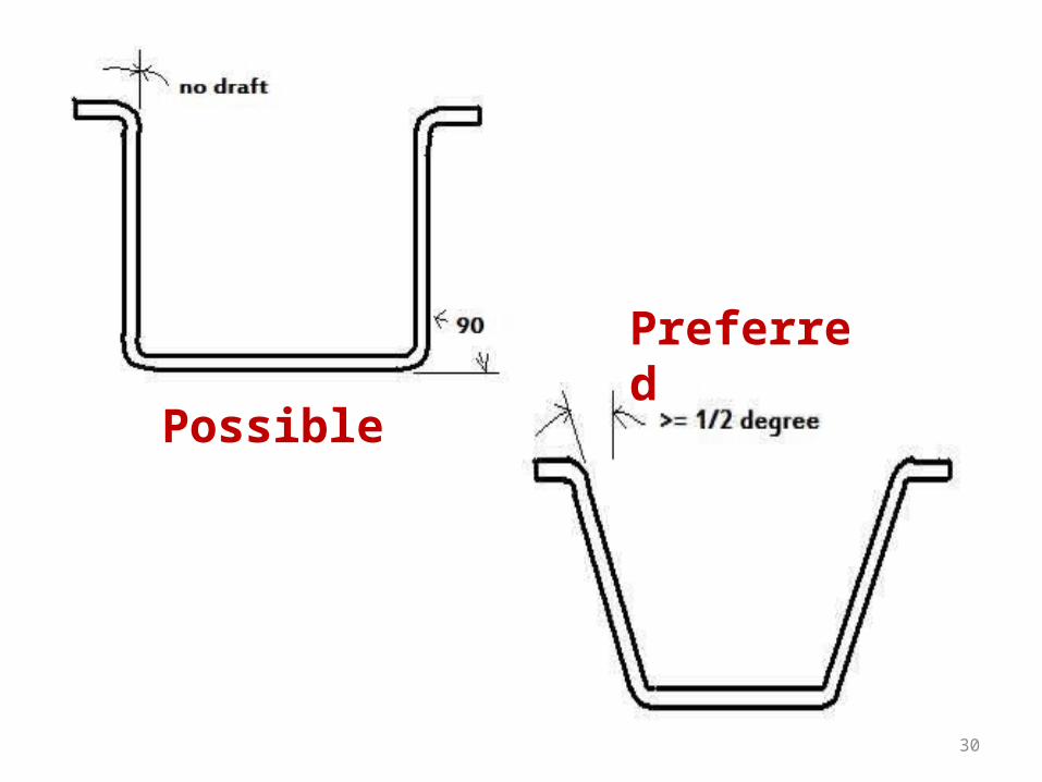
• Exactly vertical sidewalls should be avoided to reduce troubles for roll former
• Excessive roll wear and scoring of the work piece is thereby reduced
• This is done by including a draft angle of ½ degree
Vertical Sidewalls
30
Possible
Preferred
31
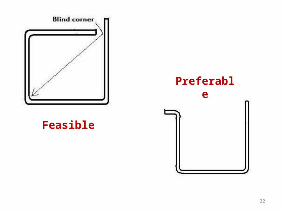
• Some feasible blind corners and radii are shown here
• When precise bends are needed, these should be avoided
• Controlling both sides of stock by rolls, facilitates accurate forming
Blind Corners
32
Feasible
Preferable
33
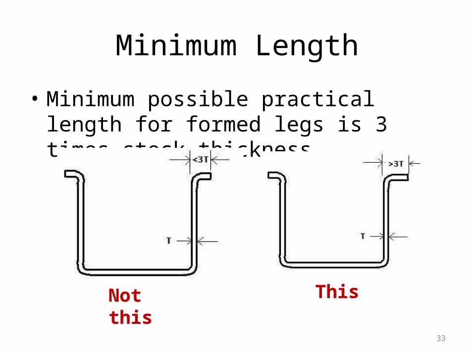
• Minimum possible practical length for formed legs is 3 times stock thickness
Minimum Length
Not this This
34
• Factors causing dimensional variations – spring back, variations in hardness, thickness, and yield point of material, tooling deviations and tooling wear, setup and adjustment of tooling and machine deflection
• Close tolerances are held with thinner stock and smaller parts
• Tighter ones are held at extra cost
Dimensional factors & Tolerances
35
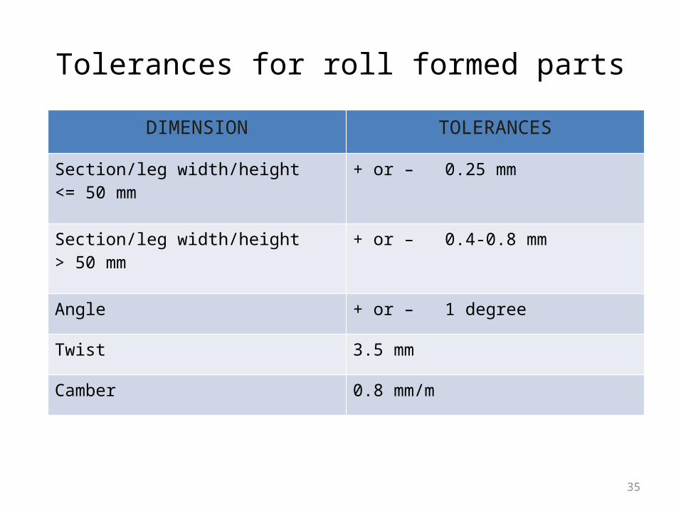
DIMENSION TOLERANCES
Section/leg width/height <= 50 mm
+ or – 0.25 mm
Section/leg width/height > 50 mm
+ or – 0.4-0.8 mm
Angle + or – 1 degree
Twist 3.5 mm
Camber 0.8 mm/m
Tolerances for roll formed parts