
Review Article Formation of Al O -HfO Eutectic EBC...
8
Review Article Formation of Al 2 O 3 -HfO 2 Eutectic EBC Film on Silicon Carbide Substrate Kyosuke Seya, 1 Shunkichi Ueno, 1 and Byung-Koog Jang 2 1 College of Engineering, Nihon University, Koriyama, Fukushima 963-8642, Japan 2 National Institute for Materials Science, Tsukuba, Ibaraki 305-0047, Japan Correspondence should be addressed to Shunkichi Ueno; [email protected] Received 27 April 2015; Revised 14 July 2015; Accepted 29 July 2015 Academic Editor: Margarida Amaral Copyright © 2015 Kyosuke Seya et al. is is an open access article distributed under the Creative Commons Attribution License, which permits unrestricted use, distribution, and reproduction in any medium, provided the original work is properly cited. e formation mechanism of Al 2 O 3 -HfO 2 eutectic structure, the preparation method, and the formation mechanism of the eutectic EBC layer on the silicon carbide substrate are summarized. Al 2 O 3 -HfO 2 eutectic EBC film is prepared by optical zone melting method on the silicon carbide substrate. At high temperature, a small amount of silicon carbide decomposed into silicon and carbon. e components of Al 2 O 3 and HfO 2 in molten phase also react with the free carbon. e Al 2 O 3 phase reacts with free carbon and vapor species of AlO phase is formed. e composition of the molten phase becomes HfO 2 rich from the eutectic composition. HfO 2 phase also reacts with the free carbon and HfC phase is formed on the silicon carbide substrate; then a high density intermediate layer is formed. e adhesion between the intermediate layer and the substrate is excellent by an anchor effect. When the solidification process finished before all of HfO 2 phase is reduced to HfC phase, HfC-HfO 2 functionally graded layer is formed on the silicon carbide substrate and the Al 2 O 3 -HfO 2 eutectic structure grows from the top of the intermediate layer. 1. Introduction Since silicon carbide ceramic and its composites show high specific strength and high oxidation resistance at elevated temperatures, these materials are promised to be used as gas turbine hot section components [1]. However, under high speed exhaust gas and high temperature normally present in these applications, the surface of silicon carbide ceramics is oxidized and the formed silica layer is easily corroded by water vapor promoting the recession of the ceramic component. For example, Yuri and Hisamatsu suggested that silicon carbide ceramics will be recessed about 3 mm under gas turbine conditions at 1523 K for 10,000 hours [2]. Hence on the application of silicon carbide and its compos- ites for gas turbine hot sections component, an oxidation- corrosion resistance environmental barrier coating (EBC) layer is required. Some oxides, such as ZrO 2 , HfO 2 , and Lu 2 Si 2 O 7 , show excellent water vapor corrosion resistance under gas turbine conditions at elevated temperatures [3, 4]. On the development of EBC for nonoxides ceramics, oxides EBC layers were prepared by plasma spraying [3]. Since the EBC layer is composed of polycrystalline solid, a small amount of glassy phase exists at the grain boundary and it can be easily corroded by water vapor under gas turbine condition; then, a porous structure is formed through the EBC layer, even if the crystalline phase of oxide EBC material shows an excellent water vapor corrosion resis- tance. e corrosive gases easily pass through the porous channel of the EBC layer and the silicon carbide substrate will be oxidized. Hence, an EBC layer without boundary glassy phase is required for the development of future EBC. On the solidification of oxides eutectic, the excess impuri- ties will be removed from the bulk by segregation [5]. Hence, the eutectic composites, especially the eutectic with ZrO 2 , HfO 2 , or Ln 2 Si 2 O 7 (Ln = rare earth) phase, are promising materials for EBC. In our previous report, an oxides eutectic EBC without boundary glassy phase and its preparation method are pro- posed [6]. In this review, we focused on the Al 2 O 3 -HfO 2 eutectic EBC and its preparation method and the formation mechanism of the Al 2 O 3 -HfO 2 eutectic EBC layer will be summarized. Hindawi Publishing Corporation Journal of Nanomaterials Volume 2015, Article ID 318278, 7 pages http://dx.doi.org/10.1155/2015/318278
Transcript of Review Article Formation of Al O -HfO Eutectic EBC...

Review ArticleFormation of Al2O3-HfO2 Eutectic EBC Film onSilicon Carbide Substrate
Kyosuke Seya1 Shunkichi Ueno1 and Byung-Koog Jang2
1College of Engineering Nihon University Koriyama Fukushima 963-8642 Japan2National Institute for Materials Science Tsukuba Ibaraki 305-0047 Japan
Correspondence should be addressed to Shunkichi Ueno uenochemcenihon-uacjp
Received 27 April 2015 Revised 14 July 2015 Accepted 29 July 2015
Academic Editor Margarida Amaral
Copyright copy 2015 Kyosuke Seya et al This is an open access article distributed under the Creative Commons Attribution Licensewhich permits unrestricted use distribution and reproduction in any medium provided the original work is properly cited
The formationmechanism of Al2O3-HfO2 eutectic structure the preparationmethod and the formationmechanism of the eutecticEBC layer on the silicon carbide substrate are summarized Al2O3-HfO2 eutectic EBC film is prepared by optical zone meltingmethod on the silicon carbide substrate At high temperature a small amount of silicon carbide decomposed into silicon andcarbon The components of Al2O3 and HfO2 in molten phase also react with the free carbon The Al2O3 phase reacts with freecarbon and vapor species of AlO phase is formed The composition of the molten phase becomes HfO2 rich from the eutecticcomposition HfO2 phase also reacts with the free carbon and HfC phase is formed on the silicon carbide substrate then a highdensity intermediate layer is formedThe adhesion between the intermediate layer and the substrate is excellent by an anchor effectWhen the solidification process finished before all of HfO2 phase is reduced to HfC phase HfC-HfO2 functionally graded layer isformed on the silicon carbide substrate and the Al2O3-HfO2 eutectic structure grows from the top of the intermediate layer
1 Introduction
Since silicon carbide ceramic and its composites show highspecific strength and high oxidation resistance at elevatedtemperatures these materials are promised to be used as gasturbine hot section components [1] However under highspeed exhaust gas and high temperature normally presentin these applications the surface of silicon carbide ceramicsis oxidized and the formed silica layer is easily corrodedby water vapor promoting the recession of the ceramiccomponent For example Yuri and Hisamatsu suggestedthat silicon carbide ceramics will be recessed about 3mmunder gas turbine conditions at 1523K for 10000 hours [2]Hence on the application of silicon carbide and its compos-ites for gas turbine hot sections component an oxidation-corrosion resistance environmental barrier coating (EBC)layer is required Some oxides such as ZrO
2 HfO
2 and
Lu2Si2O7 show excellent water vapor corrosion resistance
under gas turbine conditions at elevated temperatures [34] On the development of EBC for nonoxides ceramicsoxides EBC layers were prepared by plasma spraying [3]Since the EBC layer is composed of polycrystalline solid
a small amount of glassy phase exists at the grain boundaryand it can be easily corroded by water vapor under gasturbine condition then a porous structure is formed throughthe EBC layer even if the crystalline phase of oxide EBCmaterial shows an excellent water vapor corrosion resis-tance The corrosive gases easily pass through the porouschannel of the EBC layer and the silicon carbide substratewill be oxidized Hence an EBC layer without boundaryglassy phase is required for the development of futureEBC
On the solidification of oxides eutectic the excess impuri-ties will be removed from the bulk by segregation [5] Hencethe eutectic composites especially the eutectic with ZrO
2
HfO2 or Ln
2Si2O7(Ln = rare earth) phase are promising
materials for EBCIn our previous report an oxides eutectic EBC without
boundary glassy phase and its preparation method are pro-posed [6] In this review we focused on the Al
2O3-HfO2
eutectic EBC and its preparation method and the formationmechanism of the Al
2O3-HfO2eutectic EBC layer will be
summarized
Hindawi Publishing CorporationJournal of NanomaterialsVolume 2015 Article ID 318278 7 pageshttpdxdoiorg1011552015318278
2 Journal of Nanomaterials
(a) 14 120583ms
5120583m
(b) 14120583ms
Solid
ifica
tion
dire
ctio
n
5120583m
(c) 28120583ms
5120583m
Figure 1 Longitudinal cross section of back scattering electron SEM images for the samples prepared by unidirectional solidification insolidification rate (a) 14 120583ms (b) 14120583ms and (c) 28 120583ms respectively [7]
2 Structure Formation of Al2O3-HfO2 Eutectic
The microstructure formation of oxide eutectic compositesclosely depends on the solidification rate Commonly themicrostructure of the eutectic is formed by limited diffusionof each component during the solidification Hence it can bepredicted that a fine microstructure will be formed when theeutectic system includes a large cation such as hafnium ionandor rare earth ion Since theAl
2O3-HfO2eutectic includes
HfO2which shows an excellent corrosion resistance Al
2O3-
HfO2eutectic is a promising material for EBC system The
microstructure formation of Al2O3-HfO2eutectic is reported
in a previous work of the authors [7]The experimental procedures are described in detail in
[7]The eutectic sampleswere prepared by rapid solidificationand unidirectional solidification using an optical floatingzone apparatusThe powders of Al
2O3and HfO
2were mixed
in molar ratio of Al2O3 HfO2= 67 33 according to [8] The
mixed powder was pressed into rod shape samples of 5mm indiameter The calcination was performed at 1473K for 36 ksin air and the feed rod was preparedThe thermal cycling testfor the rapid solidified samples was performed between roomtemperature and 1673K The solidification was performed inAr atmosphere using floating zone apparatus The pressurewas controlled to 02MPa for all solidification process Xenonlamp was used as an optical source The Xenon lamp andsample put on the focus in the elliptical mirror which hastwo focuses The feed rod was hooked on upper shaft
For the experiment of unidirectional solidification anotherfeed rod was fixed with lower shaft This melting systemwas set up in a quartz tube The solidification rate wascontrolled between 14 and 28 120583ms For the experiment ofrapid solidification the molten phase drops on a copperplate The distance between the melting position and thecopper plate was fixed to 023m The residual stress for thecorundum phase in the eutectic structure was measured byRaman shiftsThe transversal and longitudinal cross sectionsof the solidified samples were observed by SEM
Figure 1 shows the longitudinal cross section SEM imagesobtained for the samples prepared by unidirectional solidifi-cation using solidification rates of (a) 14120583ms (b) 14 120583msand (c) 28120583ms respectively [7] The white phase denotesHfO2phase and dark phase denotes Al
2O3phase The
interlamellar spacing decreased with increasing solidificationrate and the relationship between the interlamellar spacing120582 and solidification rate 119877 can be expressed by 120582 prop 119877minus0437as shown in Figure 2 [7] The sample prepared by rapidsolidification process also showed a lamella structure [7]
Lopato and Shevchenko suggested that the microstruc-ture formation for Al
2O3-HfO2eutectic is very similar to
that for Al2O3-ZrO2eutectic [8] The formation mechanism
of Al2O3-ZrO2eutectic was examined by several researchers
[9ndash11] The relationship between the interlamellar spacing120582 and solidification rate 119877 can be expressed by 1205822119877 =constant for Al
2O3-ZrO2eutectic [10] For the Al
2O3-ZrO2
eutectic a lamellar structure is obtained below 3120583ms in
Journal of Nanomaterials 3
1 10 100
1
10
Solidification rate R (120583m sminus1)
120582 prop Rminus0437
Inte
rlam
ella
r spa
cing
120582(120583
m)
Figure 2 The relationship between the interlamellar spacing andsolidification rate [7]
20 40 60
Inte
nsity
I (a
u)
Diffraction angle 2120579 (∘)
Al2O3
HfO2 (t)HfO2 (m)
Figure 3 The powder X-ray diffraction pattern of the sampleprepared by rapid solidification [7]
the solidification rate and rod structure is formed above3 120583ms in the solidification rate [9ndash11] However in the caseof Al2O3-HfO2eutectic only lamellar structure is formed
even if the sample was prepared by rapid solidificationprocess Since the relation between interlamellar spacing 120582and solidification rate 119877 for Al
2O3-ZrO2and Al
2O3-HfO2is
eutectic according to Jackson-Hunt theory the diffusion ofcomponent atoms are the limiting parameter at an establishedsolidification rate for the formation of the microstructureThe differences in the microstructure formation betweenAl2O3-ZrO2and Al
2O3-HfO2are eutectic caused by the
differences between diffusion coefficients of zirconium andhafnium ions during the solidification
Figure 3 shows the powder X-ray diffraction patternof the sample prepared by rapid solidification process [7]Almost all peaks can be indexed as monoclinic HfO
2and
corundum phases However a weak peak at 2120579 = 3037∘ can
4300 4350 4400 4450
R1R2
Inte
nsity
I (a
u)
in eutectic
Ruby Δ = 32 cmminus1
Raman shift (cmminus1)
Al2O3
Figure 4 The Raman shift for Al2O3phase in the eutectic sample
[7]
be indexed as (101)t of the tetragonal HfO2 phase [12] In theAl2O3-HfO2binary phase diagram tetragonal HfO
2phase
exists above 2063K [8] On the other hand no peaks for thetetragonal HfO
2phase were detected for the sample prepared
by unidirectional solidification Since the cooling rate forunidirectional solidification is lower than that for the rapidsolidification all of the tetragonal phase is transformed intomonoclinic phase during the cooling step of the solidificationprocess
Figure 4 shows the Raman shift for Al2O3phase in the
eutectic sample prepared by unidirectional solidification andruby single crystal as a reference [7] The peaks of R1 andR2 for Al
2O3phase in eutectic sample slightly shifted from
peaks of the ruby reference Since the transformation ofHfO2phase from tetragonal to monoclinic phase involved
a large volume expansion a tensile stress will be inducedin Al2O3phase The tensile stresses for Al
2O3phase can
be estimated to 420MPa from the Raman shift [6] Eventhough a large stress is induced on the Al
2O3-HfO2interface
in the eutectic structure due to the transformation fromtetragonal tomonoclinic phase the stress is distributed to thelong Al
2O3-HfO2interface and no cracks are induced by the
transformation
3 Reactivity of Al2O3-HfO2 Componentwith Silicon Carbide Substrate at HighTemperatures
First we tried to prepare the Al2O3-HfO2eutectic film on
silicon carbide substrate by heat treatment using electricfurnace Silicon carbide bulk (JAPANFINECERAMICSCOLTD) was used as substrate In this silicon carbide bulkcarbon and boron were included as sintering agents Theslurry of Al
2O3and HfO
2with the eutectic composition
was applied to the surface of the substrate by a brush Theheat treatment was performed at 2573K under Ar flow Theheating rate was controlled to 033 Ks When the targettemperaturewas reached the power source of the furnacewasshut down
4 Journal of Nanomaterials
10mm
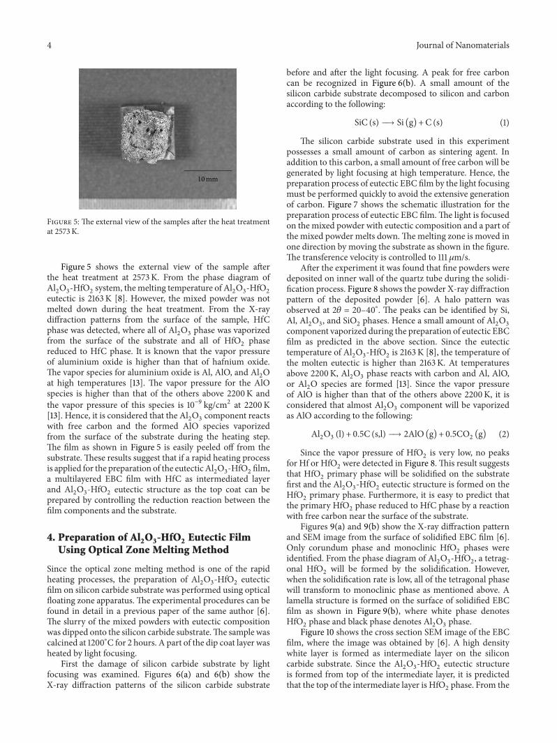
Figure 5 The external view of the samples after the heat treatmentat 2573K
Figure 5 shows the external view of the sample afterthe heat treatment at 2573K From the phase diagram ofAl2O3-HfO2system themelting temperature of Al
2O3-HfO2
eutectic is 2163 K [8] However the mixed powder was notmelted down during the heat treatment From the X-raydiffraction patterns from the surface of the sample HfCphase was detected where all of Al
2O3phase was vaporized
from the surface of the substrate and all of HfO2phase
reduced to HfC phase It is known that the vapor pressureof aluminium oxide is higher than that of hafnium oxideThe vapor species for aluminium oxide is Al AlO and Al
2O
at high temperatures [13] The vapor pressure for the AlOspecies is higher than that of the others above 2200K andthe vapor pressure of this species is 10minus9 kgcm2 at 2200K[13] Hence it is considered that the Al
2O3component reacts
with free carbon and the formed AlO species vaporizedfrom the surface of the substrate during the heating stepThe film as shown in Figure 5 is easily peeled off from thesubstrate These results suggest that if a rapid heating processis applied for the preparation of the eutecticAl
2O3-HfO2film
a multilayered EBC film with HfC as intermediated layerand Al
2O3-HfO2eutectic structure as the top coat can be
prepared by controlling the reduction reaction between thefilm components and the substrate
4 Preparation of Al2O3-HfO2 Eutectic FilmUsing Optical Zone Melting Method
Since the optical zone melting method is one of the rapidheating processes the preparation of Al
2O3-HfO2eutectic
film on silicon carbide substrate was performed using opticalfloating zone apparatus The experimental procedures can befound in detail in a previous paper of the same author [6]The slurry of the mixed powders with eutectic compositionwas dipped onto the silicon carbide substrateThe sample wascalcined at 1200∘C for 2 hours A part of the dip coat layer washeated by light focusing
First the damage of silicon carbide substrate by lightfocusing was examined Figures 6(a) and 6(b) show theX-ray diffraction patterns of the silicon carbide substrate
before and after the light focusing A peak for free carboncan be recognized in Figure 6(b) A small amount of thesilicon carbide substrate decomposed to silicon and carbonaccording to the following
SiC (s) 997888rarr Si (g) +C (s) (1)
The silicon carbide substrate used in this experimentpossesses a small amount of carbon as sintering agent Inaddition to this carbon a small amount of free carbon will begenerated by light focusing at high temperature Hence thepreparation process of eutectic EBC film by the light focusingmust be performed quickly to avoid the extensive generationof carbon Figure 7 shows the schematic illustration for thepreparation process of eutectic EBC filmThe light is focusedon the mixed powder with eutectic composition and a part ofthe mixed powder melts downThemelting zone is moved inone direction by moving the substrate as shown in the figureThe transference velocity is controlled to 111 120583ms
After the experiment it was found that fine powders weredeposited on inner wall of the quartz tube during the solidi-fication process Figure 8 shows the powder X-ray diffractionpattern of the deposited powder [6] A halo pattern wasobserved at 2120579 = 20ndash40∘ The peaks can be identified by SiAl Al
2O3 and SiO
2phases Hence a small amount of Al
2O3
component vaporized during the preparation of eutectic EBCfilm as predicted in the above section Since the eutectictemperature of Al
2O3-HfO2is 2163 K [8] the temperature of
the molten eutectic is higher than 2163K At temperaturesabove 2200K Al
2O3phase reacts with carbon and Al AlO
or Al2O species are formed [13] Since the vapor pressure
of AlO is higher than that of the others above 2200K it isconsidered that almost Al
2O3component will be vaporized
as AlO according to the following
Al2O3 (l) + 05C (sl) 997888rarr 2AlO (g) + 05CO2 (g) (2)
Since the vapor pressure of HfO2is very low no peaks
for Hf or HfO2were detected in Figure 8This result suggests
that HfO2primary phase will be solidified on the substrate
first and the Al2O3-HfO2eutectic structure is formed on the
HfO2primary phase Furthermore it is easy to predict that
the primary HfO2phase reduced to HfC phase by a reaction
with free carbon near the surface of the substrateFigures 9(a) and 9(b) show the X-ray diffraction pattern
and SEM image from the surface of solidified EBC film [6]Only corundum phase and monoclinic HfO
2phases were
identified From the phase diagram of Al2O3-HfO2 a tetrag-
onal HfO2will be formed by the solidification However
when the solidification rate is low all of the tetragonal phasewill transform to monoclinic phase as mentioned above Alamella structure is formed on the surface of solidified EBCfilm as shown in Figure 9(b) where white phase denotesHfO2phase and black phase denotes Al
2O3phase
Figure 10 shows the cross section SEM image of the EBCfilm where the image was obtained by [6] A high densitywhite layer is formed as intermediate layer on the siliconcarbide substrate Since the Al
2O3-HfO2eutectic structure
is formed from top of the intermediate layer it is predictedthat the top of the intermediate layer is HfO
2phase From the
Journal of Nanomaterials 5
SiC
20 40 60
Inte
nsity
I (a
u)
Diffraction angle 2120579 (∘)
(a)
C
20 40 60
SiC
Inte
nsity
I (a
u)
Diffraction angle 2120579 (∘)
(b)
Figure 6 The X-ray diffraction patterns (a) before and (b) after the light focusing [6]
SiC substrate
Mixed powder
Melt
Light focusing
Transfer direction
Qua
rtz t
ube
Ar 02MPa
Figure 7 The schematic illustration for preparation process ofeutectic EBC film
experimental results using electrical furnace as mentionedabove it is easy to consider that HfC phase is formed on thesilicon carbide substrate
To examine the composition of the intermediate layera line analysis for the intermediate layer was performedas indicated in Figure 11(a) The concentration of carbongradually decreases from the bottomof the intermediate layerto the top of the layer as shown in Figure 11(b) On theother hand the concentration of oxygen gradually increasesfrom the bottom of the intermediate layer to the top of thelayer This result suggests that the intermediate layer is afunctionally graded layer The primary HfO
2phase reduced
to HfC on the surface of the silicon carbide substrateThe adhesion between the intermediate layer and silicon
carbide substrate is excellent by an anchor effect as shown
SiAl
20 40 60Diffraction angle 2120579 (∘)
Al2O3
SiO2
Inte
nsity
I (a
u)
Figure 8 The powder X-ray diffraction pattern of the powderdeposited inner wall of quartz tube [6]
in Figure 10 and no crack is induced in the layer Thecoefficient of thermal expansion of HfC phase is smallerthan that of HfO
2phase and very similar to that of silicon
carbide substrate Hence the excellent adhesion between theintermediate layer and substrate is obtained
From the above experimental results the formationmechanism of Al
2O3-HfO2eutectic film by the optical zone
melting method can be explained as follows (1) a smallamount of Al
2O3component is reduced by the free carbon
and vaporized from the melting zone (2) since the composi-tion of the molten phase becomes HfO
2rich HfO
2primary
phase is formed (3) the primary HfO2phase is reduced to
HfC phase on the solidification process and high densityintermediate layer is formed (4) when the solidification
6 Journal of Nanomaterials
20 40 60
Inte
nsity
I (a
u)
Diffraction angle 2120579 (∘)
Al2O3
HfO2
HfO
2(200
)
(a)
5120583m
(b)
Figure 9 The X-ray diffraction pattern (a) and SEM image (b) from the surface of solidified EBC film [6]
SiC substrate
HfC layer
Eutectic layer
10120583m
Figure 10 Cross section SEM image of the EBC film [6]
A
B
10120583m
(a)
C
0 10 200
10
20
30
40
50
60
Hf
O
SiCsubstrate
Eutecticlayer
Atom
()
Distance D (120583m)
(b)
Figure 11 Line analysis for the first layer [6]
Journal of Nanomaterials 7
process finished before all of HfO2phase is reduced to HfC
phase HfC-HfO2functionally graded layer is formed on
the silicon carbide substrate and the Al2O3-HfO2eutectic
structure grows from the top of the intermediate layerThis process can be applied to different oxide eutectic
systems that included HfO2andor ZrO
2phase such as
CaZrO3-ZrO2and Ln
2Zr2O7-ZrO2eutectic systems
Conflict of Interests
The authors declare that there is no conflict of interestsregarding the publication of this paper
References
[1] R Naslain ldquoDesign preparation and properties of non-oxideCMCs for application in engines and nuclear reactors anoverviewrdquo Composites Science and Technology vol 64 no 2 pp155ndash170 2004
[2] I Yuri and T Hisamatsu ldquoRecession rate prediction for ceramicmaterials in combustion gas flowrdquo in Proceedings of the ASMETurbo Expo 2003 GT2003-38886 June 2003
[3] KN Lee D S Fox J I Eldridge et al ldquoUpper temperature limitof environmental barrier coatings based on mullite and BSASrdquoJournal of the American Ceramic Society vol 86 no 8 pp 1299ndash1306 2003
[4] H T Lin andM K Ferber ldquoEvaluation ofmechanical reliabilityof silicon nitride vanes after field tests in an industrial gasturbinerdquo in Proceedings of the ASME Turbo Expo GT2002-30629 2002
[5] Y Waku N Nakagawa T Wakamoto H Ohtsubo K Shimizuand Y Kohtoku ldquoThe creep and thermal stability characteristicsof a unidirectionally solidified Al
2O3YAG eutectic compositerdquo
Journal of Materials Science vol 33 no 20 pp 4943ndash4951 1998[6] K Seya B K Jang and S Ueno ldquoPreparation of environmental
barrier coating with Al2O3-HfO
2eutectic structure by optical
zone melting methodrdquo Materials Science and Technology ofJapan vol 52 no 1 pp 31ndash35 2015
[7] K Seya B K Jang and S Ueno ldquoMicrostructure formation ofAl2O3ndashHfO
2eutecticrdquo Journal of the Ceramic Society of Japan
vol 123 no 1437 pp 433ndash436 2015[8] L M Lopato and A V Shevchenko ldquoThe systemHfO
2ndashAl2O3rdquo
Neorganicheskie Materialy vol 12 no 9 pp 1623ndash1626 1976[9] F Schmid and D Viechnicki ldquoOriented eutectic microstruc-
tures in the system Al2O3ZrO2rdquo Journal of Materials Science
vol 5 no 6 pp 470ndash473 1970[10] S Bourban N Karapatis H Hofmann and W Kurz ldquoSolidi-
fication microstructure of laser remelted Al2O3-ZrO2eutecticrdquo
Acta Materialia vol 45 no 12 pp 5069ndash5075 1997[11] Y Zheng H Li T Zhou J Zhao and P Yang ldquoMicrostructure
and mechanical properties of Al2O3ZrO2eutectic ceramic
composites prepared by explosion synthesisrdquo Journal of Alloysand Compounds vol 551 no 25 pp 475ndash480 2013
[12] T-H Moon M-H Ham M-S Kim I Yun and J-MMyoung ldquoGrowth and characterization of MOMBE grownHfO2rdquo Applied Surface Science vol 240 no 1ndash4 pp 105ndash111
2005[13] R H Lamoreaux and D L Hildenbrand ldquoHigh-temperature
vaporization behavior of oxides II Oxides of Be Mg Ca Sr BaB Ga In Tl Si Ge Sn Pb Zn Cd and Hgrdquo Journal of Physicaland Chemical Reference Data vol 16 no 3 pp 419ndash443 1987
Submit your manuscripts athttpwwwhindawicom
ScientificaHindawi Publishing Corporationhttpwwwhindawicom Volume 2014
CorrosionInternational Journal of
Hindawi Publishing Corporationhttpwwwhindawicom Volume 2014
Polymer ScienceInternational Journal of
Hindawi Publishing Corporationhttpwwwhindawicom Volume 2014
Hindawi Publishing Corporationhttpwwwhindawicom Volume 2014
CeramicsJournal of
Hindawi Publishing Corporationhttpwwwhindawicom Volume 2014
CompositesJournal of
NanoparticlesJournal of
Hindawi Publishing Corporationhttpwwwhindawicom Volume 2014
Hindawi Publishing Corporationhttpwwwhindawicom Volume 2014
International Journal of
Biomaterials
Hindawi Publishing Corporationhttpwwwhindawicom Volume 2014
NanoscienceJournal of
TextilesHindawi Publishing Corporation httpwwwhindawicom Volume 2014
Journal of
NanotechnologyHindawi Publishing Corporationhttpwwwhindawicom Volume 2014
Journal of
CrystallographyJournal of
Hindawi Publishing Corporationhttpwwwhindawicom Volume 2014
The Scientific World JournalHindawi Publishing Corporation httpwwwhindawicom Volume 2014
Hindawi Publishing Corporationhttpwwwhindawicom Volume 2014
CoatingsJournal of
Advances in
Materials Science and EngineeringHindawi Publishing Corporationhttpwwwhindawicom Volume 2014
Smart Materials Research
Hindawi Publishing Corporationhttpwwwhindawicom Volume 2014
Hindawi Publishing Corporationhttpwwwhindawicom Volume 2014
MetallurgyJournal of
Hindawi Publishing Corporationhttpwwwhindawicom Volume 2014
BioMed Research International
MaterialsJournal of
Hindawi Publishing Corporationhttpwwwhindawicom Volume 2014
Nano
materials
Hindawi Publishing Corporationhttpwwwhindawicom Volume 2014
Journal ofNanomaterials

2 Journal of Nanomaterials
(a) 14 120583ms
5120583m
(b) 14120583ms
Solid
ifica
tion
dire
ctio
n
5120583m
(c) 28120583ms
5120583m
Figure 1 Longitudinal cross section of back scattering electron SEM images for the samples prepared by unidirectional solidification insolidification rate (a) 14 120583ms (b) 14120583ms and (c) 28 120583ms respectively [7]
2 Structure Formation of Al2O3-HfO2 Eutectic
The microstructure formation of oxide eutectic compositesclosely depends on the solidification rate Commonly themicrostructure of the eutectic is formed by limited diffusionof each component during the solidification Hence it can bepredicted that a fine microstructure will be formed when theeutectic system includes a large cation such as hafnium ionandor rare earth ion Since theAl
2O3-HfO2eutectic includes
HfO2which shows an excellent corrosion resistance Al
2O3-
HfO2eutectic is a promising material for EBC system The
microstructure formation of Al2O3-HfO2eutectic is reported
in a previous work of the authors [7]The experimental procedures are described in detail in
[7]The eutectic sampleswere prepared by rapid solidificationand unidirectional solidification using an optical floatingzone apparatusThe powders of Al
2O3and HfO
2were mixed
in molar ratio of Al2O3 HfO2= 67 33 according to [8] The
mixed powder was pressed into rod shape samples of 5mm indiameter The calcination was performed at 1473K for 36 ksin air and the feed rod was preparedThe thermal cycling testfor the rapid solidified samples was performed between roomtemperature and 1673K The solidification was performed inAr atmosphere using floating zone apparatus The pressurewas controlled to 02MPa for all solidification process Xenonlamp was used as an optical source The Xenon lamp andsample put on the focus in the elliptical mirror which hastwo focuses The feed rod was hooked on upper shaft
For the experiment of unidirectional solidification anotherfeed rod was fixed with lower shaft This melting systemwas set up in a quartz tube The solidification rate wascontrolled between 14 and 28 120583ms For the experiment ofrapid solidification the molten phase drops on a copperplate The distance between the melting position and thecopper plate was fixed to 023m The residual stress for thecorundum phase in the eutectic structure was measured byRaman shiftsThe transversal and longitudinal cross sectionsof the solidified samples were observed by SEM
Figure 1 shows the longitudinal cross section SEM imagesobtained for the samples prepared by unidirectional solidifi-cation using solidification rates of (a) 14120583ms (b) 14 120583msand (c) 28120583ms respectively [7] The white phase denotesHfO2phase and dark phase denotes Al
2O3phase The
interlamellar spacing decreased with increasing solidificationrate and the relationship between the interlamellar spacing120582 and solidification rate 119877 can be expressed by 120582 prop 119877minus0437as shown in Figure 2 [7] The sample prepared by rapidsolidification process also showed a lamella structure [7]
Lopato and Shevchenko suggested that the microstruc-ture formation for Al
2O3-HfO2eutectic is very similar to
that for Al2O3-ZrO2eutectic [8] The formation mechanism
of Al2O3-ZrO2eutectic was examined by several researchers
[9ndash11] The relationship between the interlamellar spacing120582 and solidification rate 119877 can be expressed by 1205822119877 =constant for Al
2O3-ZrO2eutectic [10] For the Al
2O3-ZrO2
eutectic a lamellar structure is obtained below 3120583ms in
Journal of Nanomaterials 3
1 10 100
1
10
Solidification rate R (120583m sminus1)
120582 prop Rminus0437
Inte
rlam
ella
r spa
cing
120582(120583
m)
Figure 2 The relationship between the interlamellar spacing andsolidification rate [7]
20 40 60
Inte
nsity
I (a
u)
Diffraction angle 2120579 (∘)
Al2O3
HfO2 (t)HfO2 (m)
Figure 3 The powder X-ray diffraction pattern of the sampleprepared by rapid solidification [7]
the solidification rate and rod structure is formed above3 120583ms in the solidification rate [9ndash11] However in the caseof Al2O3-HfO2eutectic only lamellar structure is formed
even if the sample was prepared by rapid solidificationprocess Since the relation between interlamellar spacing 120582and solidification rate 119877 for Al
2O3-ZrO2and Al
2O3-HfO2is
eutectic according to Jackson-Hunt theory the diffusion ofcomponent atoms are the limiting parameter at an establishedsolidification rate for the formation of the microstructureThe differences in the microstructure formation betweenAl2O3-ZrO2and Al
2O3-HfO2are eutectic caused by the
differences between diffusion coefficients of zirconium andhafnium ions during the solidification
Figure 3 shows the powder X-ray diffraction patternof the sample prepared by rapid solidification process [7]Almost all peaks can be indexed as monoclinic HfO
2and
corundum phases However a weak peak at 2120579 = 3037∘ can
4300 4350 4400 4450
R1R2
Inte
nsity
I (a
u)
in eutectic
Ruby Δ = 32 cmminus1
Raman shift (cmminus1)
Al2O3
Figure 4 The Raman shift for Al2O3phase in the eutectic sample
[7]
be indexed as (101)t of the tetragonal HfO2 phase [12] In theAl2O3-HfO2binary phase diagram tetragonal HfO
2phase
exists above 2063K [8] On the other hand no peaks for thetetragonal HfO
2phase were detected for the sample prepared
by unidirectional solidification Since the cooling rate forunidirectional solidification is lower than that for the rapidsolidification all of the tetragonal phase is transformed intomonoclinic phase during the cooling step of the solidificationprocess
Figure 4 shows the Raman shift for Al2O3phase in the
eutectic sample prepared by unidirectional solidification andruby single crystal as a reference [7] The peaks of R1 andR2 for Al
2O3phase in eutectic sample slightly shifted from
peaks of the ruby reference Since the transformation ofHfO2phase from tetragonal to monoclinic phase involved
a large volume expansion a tensile stress will be inducedin Al2O3phase The tensile stresses for Al
2O3phase can
be estimated to 420MPa from the Raman shift [6] Eventhough a large stress is induced on the Al
2O3-HfO2interface
in the eutectic structure due to the transformation fromtetragonal tomonoclinic phase the stress is distributed to thelong Al
2O3-HfO2interface and no cracks are induced by the
transformation
3 Reactivity of Al2O3-HfO2 Componentwith Silicon Carbide Substrate at HighTemperatures
First we tried to prepare the Al2O3-HfO2eutectic film on
silicon carbide substrate by heat treatment using electricfurnace Silicon carbide bulk (JAPANFINECERAMICSCOLTD) was used as substrate In this silicon carbide bulkcarbon and boron were included as sintering agents Theslurry of Al
2O3and HfO
2with the eutectic composition
was applied to the surface of the substrate by a brush Theheat treatment was performed at 2573K under Ar flow Theheating rate was controlled to 033 Ks When the targettemperaturewas reached the power source of the furnacewasshut down
4 Journal of Nanomaterials
10mm
Figure 5 The external view of the samples after the heat treatmentat 2573K
Figure 5 shows the external view of the sample afterthe heat treatment at 2573K From the phase diagram ofAl2O3-HfO2system themelting temperature of Al
2O3-HfO2
eutectic is 2163 K [8] However the mixed powder was notmelted down during the heat treatment From the X-raydiffraction patterns from the surface of the sample HfCphase was detected where all of Al
2O3phase was vaporized
from the surface of the substrate and all of HfO2phase
reduced to HfC phase It is known that the vapor pressureof aluminium oxide is higher than that of hafnium oxideThe vapor species for aluminium oxide is Al AlO and Al
2O
at high temperatures [13] The vapor pressure for the AlOspecies is higher than that of the others above 2200K andthe vapor pressure of this species is 10minus9 kgcm2 at 2200K[13] Hence it is considered that the Al
2O3component reacts
with free carbon and the formed AlO species vaporizedfrom the surface of the substrate during the heating stepThe film as shown in Figure 5 is easily peeled off from thesubstrate These results suggest that if a rapid heating processis applied for the preparation of the eutecticAl
2O3-HfO2film
a multilayered EBC film with HfC as intermediated layerand Al
2O3-HfO2eutectic structure as the top coat can be
prepared by controlling the reduction reaction between thefilm components and the substrate
4 Preparation of Al2O3-HfO2 Eutectic FilmUsing Optical Zone Melting Method
Since the optical zone melting method is one of the rapidheating processes the preparation of Al
2O3-HfO2eutectic
film on silicon carbide substrate was performed using opticalfloating zone apparatus The experimental procedures can befound in detail in a previous paper of the same author [6]The slurry of the mixed powders with eutectic compositionwas dipped onto the silicon carbide substrateThe sample wascalcined at 1200∘C for 2 hours A part of the dip coat layer washeated by light focusing
First the damage of silicon carbide substrate by lightfocusing was examined Figures 6(a) and 6(b) show theX-ray diffraction patterns of the silicon carbide substrate
before and after the light focusing A peak for free carboncan be recognized in Figure 6(b) A small amount of thesilicon carbide substrate decomposed to silicon and carbonaccording to the following
SiC (s) 997888rarr Si (g) +C (s) (1)
The silicon carbide substrate used in this experimentpossesses a small amount of carbon as sintering agent Inaddition to this carbon a small amount of free carbon will begenerated by light focusing at high temperature Hence thepreparation process of eutectic EBC film by the light focusingmust be performed quickly to avoid the extensive generationof carbon Figure 7 shows the schematic illustration for thepreparation process of eutectic EBC filmThe light is focusedon the mixed powder with eutectic composition and a part ofthe mixed powder melts downThemelting zone is moved inone direction by moving the substrate as shown in the figureThe transference velocity is controlled to 111 120583ms
After the experiment it was found that fine powders weredeposited on inner wall of the quartz tube during the solidi-fication process Figure 8 shows the powder X-ray diffractionpattern of the deposited powder [6] A halo pattern wasobserved at 2120579 = 20ndash40∘ The peaks can be identified by SiAl Al
2O3 and SiO
2phases Hence a small amount of Al
2O3
component vaporized during the preparation of eutectic EBCfilm as predicted in the above section Since the eutectictemperature of Al
2O3-HfO2is 2163 K [8] the temperature of
the molten eutectic is higher than 2163K At temperaturesabove 2200K Al
2O3phase reacts with carbon and Al AlO
or Al2O species are formed [13] Since the vapor pressure
of AlO is higher than that of the others above 2200K it isconsidered that almost Al
2O3component will be vaporized
as AlO according to the following
Al2O3 (l) + 05C (sl) 997888rarr 2AlO (g) + 05CO2 (g) (2)
Since the vapor pressure of HfO2is very low no peaks
for Hf or HfO2were detected in Figure 8This result suggests
that HfO2primary phase will be solidified on the substrate
first and the Al2O3-HfO2eutectic structure is formed on the
HfO2primary phase Furthermore it is easy to predict that
the primary HfO2phase reduced to HfC phase by a reaction
with free carbon near the surface of the substrateFigures 9(a) and 9(b) show the X-ray diffraction pattern
and SEM image from the surface of solidified EBC film [6]Only corundum phase and monoclinic HfO
2phases were
identified From the phase diagram of Al2O3-HfO2 a tetrag-
onal HfO2will be formed by the solidification However
when the solidification rate is low all of the tetragonal phasewill transform to monoclinic phase as mentioned above Alamella structure is formed on the surface of solidified EBCfilm as shown in Figure 9(b) where white phase denotesHfO2phase and black phase denotes Al
2O3phase
Figure 10 shows the cross section SEM image of the EBCfilm where the image was obtained by [6] A high densitywhite layer is formed as intermediate layer on the siliconcarbide substrate Since the Al
2O3-HfO2eutectic structure
is formed from top of the intermediate layer it is predictedthat the top of the intermediate layer is HfO
2phase From the
Journal of Nanomaterials 5
SiC
20 40 60
Inte
nsity
I (a
u)
Diffraction angle 2120579 (∘)
(a)
C
20 40 60
SiC
Inte
nsity
I (a
u)
Diffraction angle 2120579 (∘)
(b)
Figure 6 The X-ray diffraction patterns (a) before and (b) after the light focusing [6]
SiC substrate
Mixed powder
Melt
Light focusing
Transfer direction
Qua
rtz t
ube
Ar 02MPa
Figure 7 The schematic illustration for preparation process ofeutectic EBC film
experimental results using electrical furnace as mentionedabove it is easy to consider that HfC phase is formed on thesilicon carbide substrate
To examine the composition of the intermediate layera line analysis for the intermediate layer was performedas indicated in Figure 11(a) The concentration of carbongradually decreases from the bottomof the intermediate layerto the top of the layer as shown in Figure 11(b) On theother hand the concentration of oxygen gradually increasesfrom the bottom of the intermediate layer to the top of thelayer This result suggests that the intermediate layer is afunctionally graded layer The primary HfO
2phase reduced
to HfC on the surface of the silicon carbide substrateThe adhesion between the intermediate layer and silicon
carbide substrate is excellent by an anchor effect as shown
SiAl
20 40 60Diffraction angle 2120579 (∘)
Al2O3
SiO2
Inte
nsity
I (a
u)
Figure 8 The powder X-ray diffraction pattern of the powderdeposited inner wall of quartz tube [6]
in Figure 10 and no crack is induced in the layer Thecoefficient of thermal expansion of HfC phase is smallerthan that of HfO
2phase and very similar to that of silicon
carbide substrate Hence the excellent adhesion between theintermediate layer and substrate is obtained
From the above experimental results the formationmechanism of Al
2O3-HfO2eutectic film by the optical zone
melting method can be explained as follows (1) a smallamount of Al
2O3component is reduced by the free carbon
and vaporized from the melting zone (2) since the composi-tion of the molten phase becomes HfO
2rich HfO
2primary
phase is formed (3) the primary HfO2phase is reduced to
HfC phase on the solidification process and high densityintermediate layer is formed (4) when the solidification
6 Journal of Nanomaterials
20 40 60
Inte
nsity
I (a
u)
Diffraction angle 2120579 (∘)
Al2O3
HfO2
HfO
2(200
)
(a)
5120583m
(b)
Figure 9 The X-ray diffraction pattern (a) and SEM image (b) from the surface of solidified EBC film [6]
SiC substrate
HfC layer
Eutectic layer
10120583m
Figure 10 Cross section SEM image of the EBC film [6]
A
B
10120583m
(a)
C
0 10 200
10
20
30
40
50
60
Hf
O
SiCsubstrate
Eutecticlayer
Atom
()
Distance D (120583m)
(b)
Figure 11 Line analysis for the first layer [6]
Journal of Nanomaterials 7
process finished before all of HfO2phase is reduced to HfC
phase HfC-HfO2functionally graded layer is formed on
the silicon carbide substrate and the Al2O3-HfO2eutectic
structure grows from the top of the intermediate layerThis process can be applied to different oxide eutectic
systems that included HfO2andor ZrO
2phase such as
CaZrO3-ZrO2and Ln
2Zr2O7-ZrO2eutectic systems
Conflict of Interests
The authors declare that there is no conflict of interestsregarding the publication of this paper
References
[1] R Naslain ldquoDesign preparation and properties of non-oxideCMCs for application in engines and nuclear reactors anoverviewrdquo Composites Science and Technology vol 64 no 2 pp155ndash170 2004
[2] I Yuri and T Hisamatsu ldquoRecession rate prediction for ceramicmaterials in combustion gas flowrdquo in Proceedings of the ASMETurbo Expo 2003 GT2003-38886 June 2003
[3] KN Lee D S Fox J I Eldridge et al ldquoUpper temperature limitof environmental barrier coatings based on mullite and BSASrdquoJournal of the American Ceramic Society vol 86 no 8 pp 1299ndash1306 2003
[4] H T Lin andM K Ferber ldquoEvaluation ofmechanical reliabilityof silicon nitride vanes after field tests in an industrial gasturbinerdquo in Proceedings of the ASME Turbo Expo GT2002-30629 2002
[5] Y Waku N Nakagawa T Wakamoto H Ohtsubo K Shimizuand Y Kohtoku ldquoThe creep and thermal stability characteristicsof a unidirectionally solidified Al
2O3YAG eutectic compositerdquo
Journal of Materials Science vol 33 no 20 pp 4943ndash4951 1998[6] K Seya B K Jang and S Ueno ldquoPreparation of environmental
barrier coating with Al2O3-HfO
2eutectic structure by optical
zone melting methodrdquo Materials Science and Technology ofJapan vol 52 no 1 pp 31ndash35 2015
[7] K Seya B K Jang and S Ueno ldquoMicrostructure formation ofAl2O3ndashHfO
2eutecticrdquo Journal of the Ceramic Society of Japan
vol 123 no 1437 pp 433ndash436 2015[8] L M Lopato and A V Shevchenko ldquoThe systemHfO
2ndashAl2O3rdquo
Neorganicheskie Materialy vol 12 no 9 pp 1623ndash1626 1976[9] F Schmid and D Viechnicki ldquoOriented eutectic microstruc-
tures in the system Al2O3ZrO2rdquo Journal of Materials Science
vol 5 no 6 pp 470ndash473 1970[10] S Bourban N Karapatis H Hofmann and W Kurz ldquoSolidi-
fication microstructure of laser remelted Al2O3-ZrO2eutecticrdquo
Acta Materialia vol 45 no 12 pp 5069ndash5075 1997[11] Y Zheng H Li T Zhou J Zhao and P Yang ldquoMicrostructure
and mechanical properties of Al2O3ZrO2eutectic ceramic
composites prepared by explosion synthesisrdquo Journal of Alloysand Compounds vol 551 no 25 pp 475ndash480 2013
[12] T-H Moon M-H Ham M-S Kim I Yun and J-MMyoung ldquoGrowth and characterization of MOMBE grownHfO2rdquo Applied Surface Science vol 240 no 1ndash4 pp 105ndash111
2005[13] R H Lamoreaux and D L Hildenbrand ldquoHigh-temperature
vaporization behavior of oxides II Oxides of Be Mg Ca Sr BaB Ga In Tl Si Ge Sn Pb Zn Cd and Hgrdquo Journal of Physicaland Chemical Reference Data vol 16 no 3 pp 419ndash443 1987
Submit your manuscripts athttpwwwhindawicom
ScientificaHindawi Publishing Corporationhttpwwwhindawicom Volume 2014
CorrosionInternational Journal of
Hindawi Publishing Corporationhttpwwwhindawicom Volume 2014
Polymer ScienceInternational Journal of
Hindawi Publishing Corporationhttpwwwhindawicom Volume 2014
Hindawi Publishing Corporationhttpwwwhindawicom Volume 2014
CeramicsJournal of
Hindawi Publishing Corporationhttpwwwhindawicom Volume 2014
CompositesJournal of
NanoparticlesJournal of
Hindawi Publishing Corporationhttpwwwhindawicom Volume 2014
Hindawi Publishing Corporationhttpwwwhindawicom Volume 2014
International Journal of
Biomaterials
Hindawi Publishing Corporationhttpwwwhindawicom Volume 2014
NanoscienceJournal of
TextilesHindawi Publishing Corporation httpwwwhindawicom Volume 2014
Journal of
NanotechnologyHindawi Publishing Corporationhttpwwwhindawicom Volume 2014
Journal of
CrystallographyJournal of
Hindawi Publishing Corporationhttpwwwhindawicom Volume 2014
The Scientific World JournalHindawi Publishing Corporation httpwwwhindawicom Volume 2014
Hindawi Publishing Corporationhttpwwwhindawicom Volume 2014
CoatingsJournal of
Advances in
Materials Science and EngineeringHindawi Publishing Corporationhttpwwwhindawicom Volume 2014
Smart Materials Research
Hindawi Publishing Corporationhttpwwwhindawicom Volume 2014
Hindawi Publishing Corporationhttpwwwhindawicom Volume 2014
MetallurgyJournal of
Hindawi Publishing Corporationhttpwwwhindawicom Volume 2014
BioMed Research International
MaterialsJournal of
Hindawi Publishing Corporationhttpwwwhindawicom Volume 2014
Nano
materials
Hindawi Publishing Corporationhttpwwwhindawicom Volume 2014
Journal ofNanomaterials
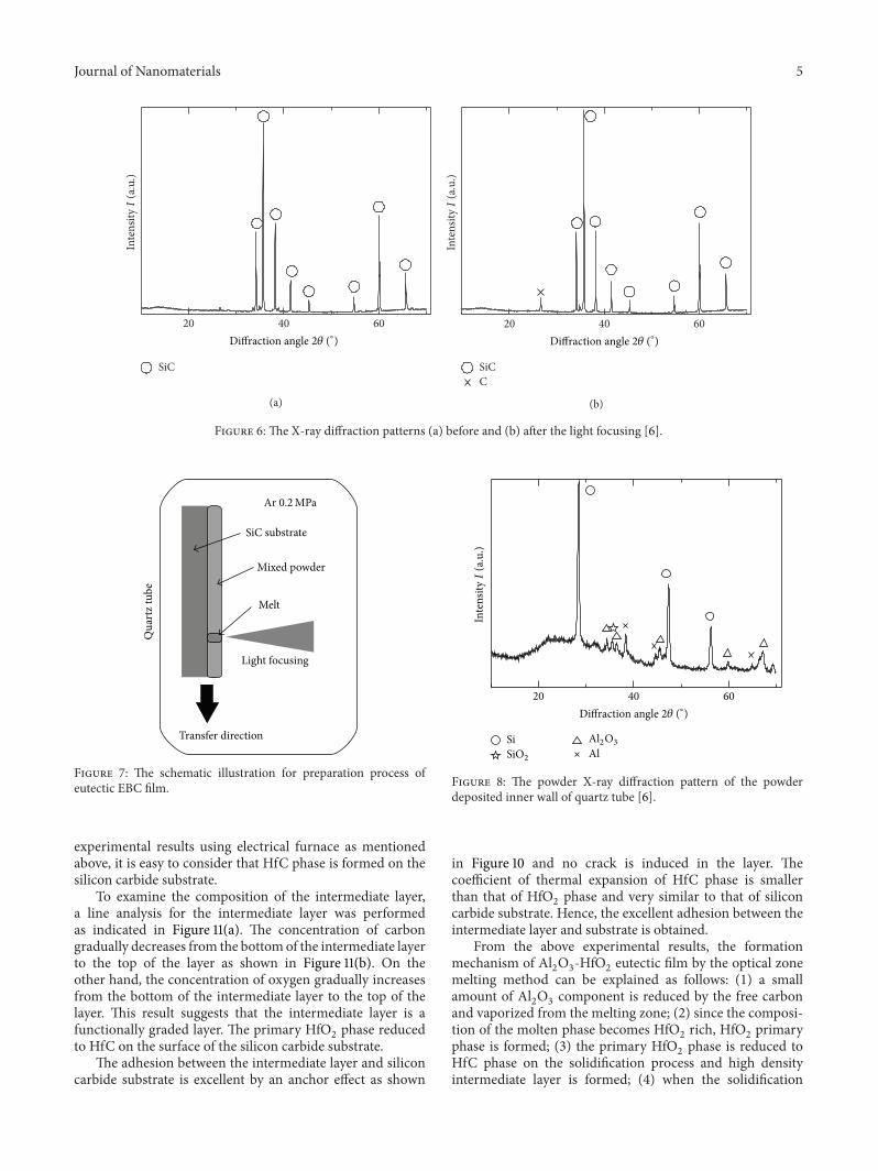
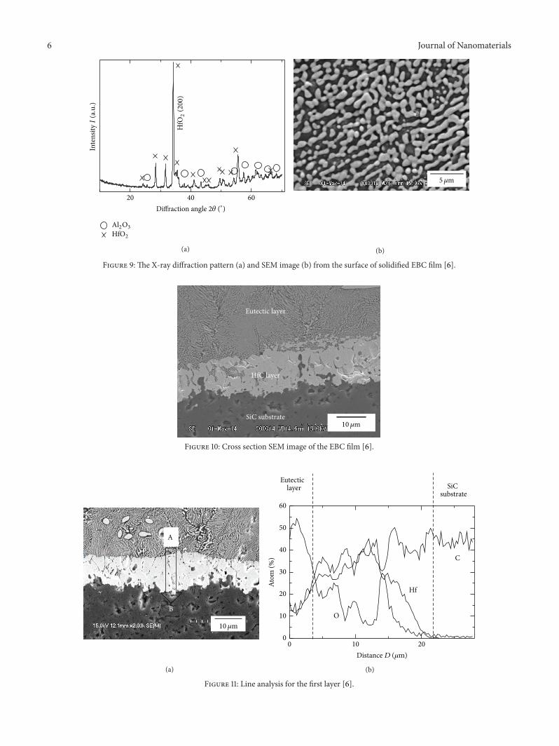