
REPORT RESUMES - ERIC - Education Resources ... RESUMES ED 021 126 VT 005 709 AUTOMOTIVE DIESEL...
39
REPORT RESUMES ED 021 126 VT 005 709 AUTOMOTIVE DIESEL MAINTENANCE 2. UNIT XXV, MICHIGAN/CLARK TRANSMISSION--TROUBLESHOOTING. HUMAN ENGINEERING INSTITUTE, CLEVELAND, OHIO REPORT NUMBER AM-2-25 PUB DATE 19 OCT 67 MINNESOTA STATE DEPT. OF EDUCATION, ST. PAUL EDRS PRICE MF-$0.25 HC-$1.60 38F. DESCRIPTORS- *STUDY GUIDES, *TEACHING GUIDES, *TRACE AND INDUSTRIAL EDUCATION, *AUTO MECHANICS (OCCUPATION), *EQUIPMENT MAINTENANCE, KINETICS, DIESEL ENGINES, MOTOR VEHICLES, ADULT VOCATIONAL EDUCATION, TRANSPARENCIES, PROGRAMED MATERIALS, PROGRAMED INSTRUCTION, INDIVIDUAL INSTRUCTION, INSTRUCTIONAL FILMS, THIS MODULE OF A 25-MODULE COURSE IS DESIGNED TO DEVELOP AN UNDERSTANDING OF TROUBLESHOOTING PROCEDURES FOR A SPECIFIC TRANSMISSION USED ON DIESEL POWERED EQUIPMENT. TOPICS ARE (1) PRELIMINARY CHECKS, (2) PRESSURE AND OIL FLOW CHECKS, (3) TROUBLESHOOTING TABLES, (4) TROUBLESHOOTING VEHICLES UNDER FIELD CONDITIONS, AND (5) ANALYZING UNACCEPTABLE INSPECTION RESULTS. THE MODULE CONSISTS OF A SELF-INSTRUCTIONAL PROGRAMED TRAINING FILM "MICIGAN/CLARK TRANSMISSION--TROUBLESHOOTING" AND OTHER MATERIALS. SEE VT V05 685 FOR FURTHER INFORMATION. MODULES IN THIS SERIES ARE AVAILABLE AS VT 005 685 - VT 005 709. MODULES FOR "AUTOMOTIVE DIESEL MAINTENANCE 1" ARE AVAILABLE AS VT 005 655 - VT 005 684. THE 2-YEAR PROGRAM OUTLINE FOR "AUTOMOTIVE DIESEL MAINTENANCE 1 AND 2" IS AVAILABLE AS VT 006 006. THE TEXT MATERIAL, PROGRAMED TRAINING FILM, AND THE ELECTRONIC TUTOR MAY BE RENTED (FOR$1.75 PER WEEK) OR PURCHASED FROM THE HUMAN ENGINEERING INSTITUTE, HEADQUARTERS AND DEVELOPMENT CENTER, 2341 CARNEGIE AVENUE, CLEVELAND, OHIO 44115. (MC)
Transcript of REPORT RESUMES - ERIC - Education Resources ... RESUMES ED 021 126 VT 005 709 AUTOMOTIVE DIESEL...

REPORT RESUMESED 021 126 VT 005 709AUTOMOTIVE DIESEL MAINTENANCE 2. UNIT XXV, MICHIGAN/CLARKTRANSMISSION--TROUBLESHOOTING.HUMAN ENGINEERING INSTITUTE, CLEVELAND, OHIOREPORT NUMBER AM-2-25 PUB DATE 19 OCT 67MINNESOTA STATE DEPT. OF EDUCATION, ST. PAULEDRS PRICE MF-$0.25 HC-$1.60 38F.
DESCRIPTORS- *STUDY GUIDES, *TEACHING GUIDES, *TRACE ANDINDUSTRIAL EDUCATION, *AUTO MECHANICS (OCCUPATION),*EQUIPMENT MAINTENANCE, KINETICS, DIESEL ENGINES, MOTORVEHICLES, ADULT VOCATIONAL EDUCATION, TRANSPARENCIES,PROGRAMED MATERIALS, PROGRAMED INSTRUCTION, INDIVIDUALINSTRUCTION, INSTRUCTIONAL FILMS,
THIS MODULE OF A 25-MODULE COURSE IS DESIGNED TO DEVELOPAN UNDERSTANDING OF TROUBLESHOOTING PROCEDURES FOR A SPECIFICTRANSMISSION USED ON DIESEL POWERED EQUIPMENT. TOPICS ARE (1)PRELIMINARY CHECKS, (2) PRESSURE AND OIL FLOW CHECKS, (3)
TROUBLESHOOTING TABLES, (4) TROUBLESHOOTING VEHICLES UNDERFIELD CONDITIONS, AND (5) ANALYZING UNACCEPTABLE INSPECTIONRESULTS. THE MODULE CONSISTS OF A SELF-INSTRUCTIONALPROGRAMED TRAINING FILM "MICIGAN/CLARKTRANSMISSION--TROUBLESHOOTING" AND OTHER MATERIALS. SEE VTV05 685 FOR FURTHER INFORMATION. MODULES IN THIS SERIES AREAVAILABLE AS VT 005 685 - VT 005 709. MODULES FOR "AUTOMOTIVEDIESEL MAINTENANCE 1" ARE AVAILABLE AS VT 005 655 - VT 005684. THE 2-YEAR PROGRAM OUTLINE FOR "AUTOMOTIVE DIESELMAINTENANCE 1 AND 2" IS AVAILABLE AS VT 006 006. THE TEXTMATERIAL, PROGRAMED TRAINING FILM, AND THE ELECTRONIC TUTORMAY BE RENTED (FOR$1.75 PER WEEK) OR PURCHASED FROM THE HUMANENGINEERING INSTITUTE, HEADQUARTERS AND DEVELOPMENT CENTER,2341 CARNEGIE AVENUE, CLEVELAND, OHIO 44115. (MC)
STUDY AND READING MATERIALS
MAINTENANCE
MICHIGAN /CLARK TRANSMISSION --TROUBLESHOOTING
UNIT XXV
SECTION A PRELIMINARY CHECKS
SECTION B PRESSURE AND OIL FLOWCHECKS
SECTION C TROUBLESHOOTING TABLES
SECTION D TROUBLESHOOTING VEHICLESUNDER FIELD CONDITIONS
SECTION E ANALYZING UNACCEPTABLEINSPECTION RESULTS
AM 2-2510/19/67
Human Engineering Minn. State Dept. of Ed.Institute Vocational Education
U.S. DEPARTMENT OF HEALTH, EDUCATION & WELFARE
OFFICE OF EDUCATION
THIS DOCUMENT HAS BEEN REPRODUCED EXACTLY AS RECEIVED FROM THE
PERSON OR ORGANIZATION ORIGINATING IT. POINTS OF VIEW OR OPINIONS
STATED DO NOT NECESSARILY REPRESENT OFFICIAL OFFICE OF EDUCATION
POSITION OR POLICY.
HUMAN ENGINEERING INSTITUTE-

AM 2_25
This Unit is a troubleshooting guide for the Michigan/Clark transmissionsand associated components. It is designed to aid the mechanic in locatingthe source of difficulty in a malfunctioning piece of equipment. Remember,that it is important to consider the torque converter,charging pump, trans-mission, oil cooler and connecting oil lines as a complete system whenisolating the source of trouble, since the proper operation of any componentwithin these systems depends greatly on the condition and operation of theothers.
SECTION A PRELIMINARY CHECKS
MECHANICAL CHECKS -- Prior to checking any part of the system froma hydraulic standpoint, the following mechanical checks should be made:
1. Check to be sure that all control lever linkage isproperly connected and adjusted at all connectingpoints.
2. Check shift levers and rods for binding or restrictionsin travel that would prevent full engagement. Shiftthe levers by hand at transmission case; if fullengagement cannot be obtained, the problem may be incontrol cover and valve assembly.
HYDRAULIC CHECKS -- Before checking the torque converter, check thetransmission and associated hydraulic systems for pressure and rate ofoil flow.
It is essential that the oil level in transmission be checked. This shouldbe done with oil temperature of 180 to 200 F. DO NOT ATTEMPT THESECHECKS WITH COLD OIL. To bring the oil temperature to this specifica-tion, it is necessary either to work the machine or stall out the converter.Where the former means is impractical, the latter means should beemployed as follows:
1

AM 2-25
Block wheels and apply parking brake. Engage shiftlevers in forward direction and the highest speed gear.Accelerate engine half to three-quarter throttle.
Hold stall until desired converter outlet temperatureis reached.CAUTION: FULL THROTTLE STALL SPEEDSHELD FOR AN EXCESSIVE LENGTH OF TIMEWILL OVERHEAT THE CONVERTER.
SECTION B -- PRESSURE AND OIL FLOW CHECKS
Whenever improper performance is evident, the basic pressure and oilflow checks should be performed and recorded. It also is recommendedthat these checks be taken periodically as a preventive maintenancemeasure. Doing so can detect difficulties in advance of actual breakdown,thus permitting a scheduling of the repair operation. Likewise, repair ofminor difficulties can be made at considerably less cost and downtime thanif they are delayed until a major and complete breakdown occurs.
Comparing the results of these checks with specifications, and with eachother, will indicate, in most cases, the basic item or assembly in thesystem that is the source of difficulty. Further checking of the assemblywill isolate the specific cause of trouble.
OIL PRESSURE AT CONVERTER OUT PORT -- Install a hydraulicpressure gauge at the PRESSURE connection on the converter regulatorvalve of CONVERTER OUT. Check and record the oil pressure at 2000rpm and at maximum speed (engine at full throttle). For the model seriesC-8000, the maximum pressure is 60 to 70 psi. For model series C-16000,it is 70 to 80 psi.
2 -

AM 2-25
OIL PRESSURE AT CONVERTER IN PORT -- Install a hydraulic pressuregauge at the PRESSURE connection at CONVERTER IN. Check and recordthe oil pressure at stall and at maximum speed (engine at full throttle).Pressure must not go below 20 psi. NOTE : If pressures at converter outare available, converter in port pressure check is not necessary.
CONVERTER CHARGING PUMP -- If a flow meter is available, install itin the line between the converter charging pump and oil filters. The flowmeter must be able to withstand 300 psi.
Disconnect the hose between the pump and filter at the filter end and, usingsuitable fittings, connect it to the pressure port of the tester. Install ahose between the filter and tester, connecting it to the reservoir port ofthe tester.
DO NOT USE TESTER LOAD VALVE AT ANY TIME DURING TEST.
When taking the flow reading, all readings should be taken on the first(left) half of the flow gauge. Whenever the needle points to the right halfof the gauge, correct by switching to a higher scale.
If a flow meter is not available for checking converter pump output, pro-ceedvith manual transmission and converter checks. If the convertershows leakage within specifications and if clutch pressures are all equalwithin five psi, the converter pump must be inspected for wear.
Each Michigan/Clark transmission assembly is equipped with a converterpump of a certain capacity, varying from 11 to 65 gallons, depending on themodel. Check the specifications for the capacity of the new pump on themodel being tested.
A 20 percent tolerance below the capacity figure listed is permissible.However, if pump output is 20 percent or more BELOW the specifiedrating, it must be replaced -- NOT rebuilt.

AM 2-25
TRANSMISSION CLUTCH LEAKAGE Check clutch pressures at low engineidle with oil at an operating temperature of 180 to 200 F. Engine speedmust remain constant during entire leakage check. Shift the levers intoforward and 1st speed, 2nd speed, 3rd speed, 4th speed, 5th speed, 6thspeed, 7th speed and 8th speed. Record all pressures. Shift the directionlever into reverse and record the pressure. All pressures must be equal,within 5 psi. If clutch pressure varies in any one clutch more than 5 psi,repair the clutch. All pressures must be taken with two clutches engaged.
If a flow meter is available, install the meter in the line coming out of theconverter pump. Check pump volume at 2000 rpm and at low engine idle.Record these readings.
Install the flow meter in the line coming from the transmission to theconverter. Check oil volume at low idle in the following speed selectionsand record the readings.
Forward - 1st speedForward - 2nd speedForward - 3rd speedForward - 4th speed
Forward -5th speedForward -6th speedForward -7th speedForward -8th speed
Reverse - 1st speed
Subtract readings in each speed from pump volume reading to get trans-mission clutch leakage.
EXAMPLE : Pump volume at idle - 8 gal.
Forward - 1st speed 6 gal Pump volume 8 gal.Forward - 2nd speed 6 gal. Forward - 1st speedForward - 3rd speed 6 gal. 6 gal.Forward - 4th speed 6 gal. Clutch leakage 2 gal.Reverse - 1st speed 6 gal.
4

AM 2-25
If clutch leakage varies more than 1 gallon, repair the clutch.
LEAKAGE IN TRANSMISSION CLUTCHES
Leakage in 3000 series must not exceed 4 gal. max.Leakage in 5000 series must not exceed 4 gal. max.Leakage in 8000 series must not exceed 6 gal. max.Leakage in 16000 series must not exceed 7 gal. max.
CONVERTER LUBE FLOW -- Disconnect CONVERTER DRAINBACK lineat the transmission with the engine running at 2000 rpm, and measure theoil into a gallon container. Measure oil leakage for 15 seconds andmultiply the volume of oil by four to get gallons per minute leakage.
LEAKAGE IN CONVERTER
Leakage in C270 series not to exceed 2 gal. max.Leakage in C8000 series not to exceed 5 gal. max.Leakage in C16000 series not to exceed 5 gal. max.
SECTION C -- TROUBLESHOOTING TABLES
The following tables indicate CAUSE or malfunction of the equipment and aREMEDY for the problem.

Table I Troubleshooting
LOW FLOW THROUGH COOLER WITH HIGH CONVERTER OUT PRESSURE
CAUSE REMEDY
1. Plugged oil cooler, indicatedif transmission lube pressureis low
1. Back flush and clean oilcooler
2. Restricted cooler return line 2. Clean out lines
3. Lube oil ports in transmissionplugged, indicated if trans-mission lube pressure is high
OVER-HEATING
1. Worn oil sealing rings
2. Worn oil pmp
3. Low oil level
4. Pump suction line taking
3. Check lube lines for restric-tions
1. Remove, disassemble and re-build converter assembly
2. Replace
3. Fill to proper level
4. Check oil line connectionsair and tighten securely
NOISY CONVERTER
1. Worn coupling gears
2. Worn oil pump
3. Worn or damaged bearings
LACK OF POWER
1. Replace
2. Replace
3. A complete disassembly willbe necessary to determinewhich bearing is faulty
1. Low engine rpm at con- 1. Tune engine check governorverter stall
2. Over-heating 2. Make corrections as explainedin over-heating above

AM 2-25
Table I Troubleshooting (cont'd.)
LOW CLUTCH PRESSURE WITH NORMAL CLUTCH LEAKAGE
CAUSE REMEDY
1. Low oil level 1. Fill to proper level
2. Broken spring in transmission 2. Replace spring
regulator valve
3. Clutch pressure regulator valvespool stuck in open position
4. Faulty charging pump 4. See paragraph on chargingpump output below
3. Clean valve spool and sleeve
LOW CLUTCH PRESSURE WITH EXCESSIVE CLUTCH LEAKAGE
1. Broken or worn clutch pistonsealing rings
2. Clutch drum bleed valve ballstuck in open position
3. Broken or worn sealing ringson clutch support
4. Low converter charging pumpoutput
1. Replace sealing rings
2. Clean bleed valve thoroughly
3. Replace sealing rings
4. See paragraph on chargingpump output below
LOW CONVERTER CHARGING PUMP OUTPUT
1. Low oil level
2. Sump screen plugged
3. Air leaks at pump intake hoseand connections or collapsedhose
1. Fill to proper level
2. Clean screen and sump
3. Tighten all connections orreplace hose if necessary
4. Defective oil pump 4. Replace pump
-7 gm,

AM 2-25
Table I Troubleshooting (cont'd.)
LOW FLOW THROUGH COOLER WITH LOW CONVERTER IN PRESSURE
CAUSE REMEDY
1. Defective safety bypass valve 1: Replace springspring
2. Converter bypass valve partially 2. Check for worn bypass ball
open seat
3. Excessive converter internalleakage. Check converterlube flow
4. Broken or worn sealing ringsin transmission clutches
8 ON.
3. Remove, disassemble,and re-build converter assembly,replacing all worn or damagedparts
4. See paragraph on clutchleakage on preceding page

AM 2-25
Table II Troubleshooting the hydraulic shift control
system
NOTE: Clutch pressure must be up to specifications before any ofthe following conditions are checked.
DELAYED SHIFT
CAUSE
1. Check valve stuck open
2. Check valve spring broken
3. Accumulator precharge low
4. Restriction in supply line
REMEDY
1. Remove, clean or replace
2. Replace
3. Precharge with nitrogen gasto 100-1 10. psi
4. Clean or replace
NO HIGH FORWARD CLUTCH ENGAGEMENT
1. Range hose plugge
2. H I LO valve stuck-
_14. 'Clean or replace'llioSP
Remove spotif, -4-ete." rmine
cause -StUking,
CLUTCH AT THE WRONG TIME
Mists 'ttliO'Sedbetween. cohttol
Valve.and transmission con7trot cover
.
1 -leIocate prdpep,__
positions
CLUTCHES NOT ENGAGING
1. Hoses crossed.:between controlvalve- and transmission con;-
trot. cover
2. Speed valves in transmissioncontrol cover in wrongsequepOd-''
3. Actuating.plungers .-t12610,4
bore
Relocate hoses in properpositions.
Remove speed ii4.1774s and
replace in proper position
_gepovp, plung0t$ determine

AM 2-25
SECTION D -- TROUBLESHOOTING VEHICLES UNDERFIELD CONDITIONS
In this troubleshooting section there are suggested charts which may beuseful when inspecting or troubleshooting the vehicles.
Refer to Figure 1 to install gauges at the proper locations when performingthe following checks.
1. 400 psi pressure gauge at location"B" to check clutchpressure at low idle, hot oil.
2. 200 psi pressure gauge at location "C" to check con-verter in pressure at stall and in neutral at 2000 rpm.
3. 200 psi pressure gauge at location "D" to check con-verter internal pressure at 2000 rpm and at HIGHFREE IDLE.
4. 100 psi pressure gauge to check lube pressure atlocation "F" at 2000 rpm and at HIGH FREE IDLE.
5. Converter leakage from converter drainback line.
With oil hot, disconnect drainback line at converter, then use a hose longenough to reach outside of the machine. Measure leakage for 15 secondsinto a gallon measure. Multiply the oil leakage by four (4) to get gallonsper minute. See troubleshooting chart for maximum leakage.
Pressure at "B" gives you condition of transmission.Pressure at "C" gives you condition of pump andconverter.Pressure at "D" gives you condition of cooler at highrpm.Pressure at "F" gives you condition of transmissionlube to bearings and clutches. The normal pressure is6 to 12 psi at 2000 rpm. Oil volume is the only thingthat will create this pressure. If pressure is lowerthan normal, it means there is a low oil volumecondition.
Check pump output or inspect converter charging pump. If pressure ishigher than 25 psi at high free idle, then the tubing which guides the oilto the bearing and clutches is plugged. See Figure 2.
- 1 0 -

ALL PRESSURE CHECKS MADE.WITH HOT OIL
"B" 180 psi to 220 psi @ low engine idle
"C"
80 psi @ 2000
rpm trans. in neutral
40 psi
@ 2000 rpm stall.
60 psi
@ high and low engine idle
28 psi
@ 2000 rpm
"F"
8 psi @ 2000 rpm
\\\\
Oil
Coo
ler
IID
I!
II
I I
S
Con
vert
er
Drain to
Trans. Sump
Pum
pn
e
*14r
ywy
.101
1111
11.
Suc
tion
from
Tra
nsm
issi
on S
ump
the above pressures are under normal
condition with a thirty-one gallon
pump
all pressures are taken at 2000
rpm
except clutch pressure; clutch pressure
is taken at low engine idle
Fig. 1,
Transmision
"A"
"B" C"
"D"
"E"
"H"
PU
MP
' OU
T P
UT
CLU
TC
H P
RE
SS
UR
EC
ON
VE
RT
ER
IN P
RE
SS
UR
EC
ON
VE
RT
ER
INT
ER
NA
L P
RE
SS
UR
EC
OO
LER
IN P
RE
SS
UR
ELU
B P
RE
SS
UR
E'
CO
NV
ER
TE
R L
EA
KA
GE
TR
AN
SM
ISS
ION
LE
AK
AG
E
Con
vert
erS
afet
y V
alve
."F
"
v
`r J 0
fa,
Low Forward
Reverse
io i
CW
W:4
kOIN
DO
OM
11/4
10C
lutc
h P
ress
ure
Reg
ulat
ing
Val
ve
Shu
t Off
Spo
ol
(Tra
ctor
Sho
vels
Onl
y)
NO
W.
db*180 -220 psi
control internal oil flow
_f
Nt.j
k.1s
t
..!--
i
Ie.."
2nd
- -
-..;.
0 3r
d..-
,
I"%
4th
0
Spe
ed S
elec
tor
Spo
olH
i For
war
dH
i & L
o F
orw
ard
Spo
ol4F
orw
ard
& R
ever
se S
pool
5-90 psi
no pressure

front-inside
engine side of case
clutch pressure
shows flow to the clutches
19
20
21 22
23
24
25
26
Typical Section
11 places on
control cover face
8 Typical Section
17 places
on front &
rear faces of
case
9
10
11
12 13
Section A-A
3-places
Section B-8
3-places
16 15
14
Section C-C
11.42.2
Transmission internal tubing
rear-inside
opposite engxee
side of case
lube pressure
shows flow to the bearings
and clutch disc
27

AM 2-25
The cooler has a normal 10 psi drop across the inlet and outlet. If a 150psi gauge is installed at location "E" (see Figure 1), the gauge should showapproximately 43 psi at 2000 rpm. This pressure at location "E" is acomposite of the resistance that creates 43 psi. See example below.
EXAMPLE:
Five to 10 psi for each line going to and from cooler. Ten to 30 psi dropacross cooler or back pressure in cooler. Six to 12 psi lube pressure attransmission location "F".
Add these pressures to get the total resistance at location "E".
Average 14 psi linesAverage 20 psi across coolerAverage 9 psi lube
43 psi normal at location "E"
NOTE: The above check indicates the condition of the converter, trans-mission, pump and cooler.
The following tables indicate the allowable engine stall speeds for fluid use.NOTE: These figures are current as of this publication. However, theyare subject to change periodically, so check the appropriate maintenancemanual.

MODEL
ENGINE
CONVERTER
MAIN RELIEF
PRESSURE
MINIMUM ENGINE
SPEED
psi
rpm
55-111
F-265 (87)
12
2200
1550
3-53
80
12
2200
1600
75-111
F-283 (100)
12
1900
1650
4-53 (108)
12
1400
1750
85-111
C-160 (128)
13
2150
1700
4-53 (118)
13
2150
1400
125-IIIA
V8R-220 (220)
14
2250
1700
V6-200 (130)
14
2000
1400
175-111
V8R-240 (230)
15
1850
1200
6V-71N65 (228)
15
1850
1300
175-IIIA
6V-71N65 <228)
15
1850
1300
8V-71N60 (290)
15
2000
1750
275-111
8V-71N65 (304)
16
1750
1500
NT-310 (310)
16
1750
1550
275-IIIA
NT-335 (335)
16
1750
1700
475-IIIA
VT12-635 (620)
17
2000
1800
Table III
Minimum allowable stall
speeds with main pump
at relief
pressure
1 tv
C.7
1

1
MODEL
ENGINE
CONVERTER
MAIN RELIEF
PRESSURE
MINIMUM ENGINE SPEED
CONV,
W/PUMP
psi
rpm
rpm
180 -
III
C-175 (162)
14
1350
2100
1800
6V-53-45 (162)
14
1350
2100
1800
280 -
III
NT-290 (290)
16
1500
2050
1800
NT-310 (310)
16
1500
2100
1900
8V-71N60 (290)
16
1500
2000
1750
280 -
IIIA
8V-71N65 (304)
16
1350
2050
1800
NT-310 (310)
16
1350
2050
1850
380
- III
12V-71N65 (456)
17
1250
2050
1900
Table IV Minimum engine stall speeds with main
pump at relief and at
neutral
tv
CJ1

MODEL NOMINAL MAXIMUM
55111 15 35
75111 20 40
85111 20 40
125111 20 40
12511IA 10 30
175111 10 30
175IIIA 10 30
275111 10 30
27511IA 10 30
475IIIA 15 35
180111 15 35
280111 10 38
280IIIA 10 30
380111 5 25110III 15 35110H 15. 35310111 30 50310H 30 50
All values at 2000 rpm with Type A converter oil at200 to 250 F. Data will vary slightly depending onspeed ratio,
Table V Oil cooler pressure drops for series III,III-A Michigan/Clark "shovels and dozers

AM 2-25
The following Charts are typical of what may be found when two differentvehicles are inspected. Notice that in Chart I, the vehicle checked outall right. In Chart II, however, the readings indicate work to be done onthe vehicle before it is returned to service.

Chart I
Acceptable inspection
results
500 - 550 rpm
Low engine idle
Engine stall speed (see stall procedures)
High free idle (hfi)
*Converter internal pressure @ low idle
1500 @ 1750 psi
2300-2400 rpm
60 psi
@ high free idle
70 psi
*Converter in pressure @ stall -
2000 rpm
40 psi
@ 2000 rpm,shift lever in neutral
80 psi
*Lube pressure @ 2000 rpm and hfi
6 to 12 psi
10 - 15 psi
*Pump volume @ low idle and 2000 rpm
6 to 10 gpm
31
gpm
Converter leakage @ 2000 rpm
3 gal.
*Transmission clutch pressure and leakage @ low idle
1st Gear 2 Gal.
190
LO-For-lst
1."
2nd Gear 2 Gal
-190
HI-For-lst
IX)
3rd Gear 2 Gal.
190
LO-For-2nd
With flow meter in line from transmission to the
4th Gear 2 Gal.
190
HI-For-2nd
converter, check oil volume at low idle in each
5th Gear 2 Gal
190
LO-For-3rd
speed.
Subtract oil volume coming out of trans-
6th Gear
2. G
al.
190
HI-For-3rd
mission in each speed from pump volume.
7th Gear 2 Gal.
190
LO-For-4th
8th Gear 2 Gal.
190
HI-For-4th
Reverse Gear 2 Gal.
190
Reverse-4th
*Normal pressure and oil flow

Chart II
Unacceptable inspection results
Low engine idle
Engine stall speed (see stall procedures)
High free idle (hfi)
*Converter internal pressure @ low idle
@ hfi
*Converter in pressure @ stall
- 2000 rpm
@ 2000 rpm,shift lever in neutral
*Lube pressure @ 2000 rpm and hfi
*Pump volume @ low idle and 2000 rpm
Converter leakage @ 2000 rpm
Transmission clutch pressure and leakage @ low idle
With flow meter in line from transmission to the
converter, check oil volume at low idle in each
speed.
Subtract oil volume coming out of trans-
mission in each speed from pump volume.
*Low pressure, low rpm, low volume
2 gal.
650 - 700 rpm
1875 rpm
2100 rpm
45 psi
80 psi
18 psi
35 psi
5 ps
i24 gpm
6 gal.
1st Gear 2 gal.
190
L0- For -lst
2nd Gear 2 aal.
190
HI-For-lst
3rd Gear 2 gal.
190
L0-For-2nd
4th Gear 2 gal.
190
HI-For-2nd
5th Gear 5 aal.
184
LO-For-3rd
6th Gear 5 gal.
184
HI-For.43rd
7th Gear 2 gal.
190
L0 -For-4th
8th Gear 2 gal.
190
HI-For-4th
Reverse Gear 2 gal.
190
Reverse-4th
cn
%4i .
4, s
tPsk
ss,
, 1,4
ls f
t:

AM 2-25
SECTION E -- ANALYZING UNACCEPTABLE INSPECTIONRESULTS
In this section, a study of the figures obtained from inspecting the vehicle
in Section D, Chart II, is presented. A possible remedy is given for the
malfunctions indicated.
1. Low engine idle - 650 to 700 rpmCorrect engine idle speed.
2. Engine stall speed - 1875 rpmCheck engine for defects to stall speed.
3. High free idle - 2100 rpmCorrect engine high free idle speed.
4. Converter internal pressure at low idle - 45 psiCheck converter regulating valve for brokenspring, or stuck in open position; low pumpvolume; low oil level; converter internalleakage.
Converter internal pressure high at hfi - 80 psiCheck cooler for restriction; check lobetubing for foreign material; check lines forrestriction; check converter regulatingvalve for sticking in closed position; cold oil.
6. Converter in pressure at stall - 18 psiCheck pump volume; check transmissionleakage; check oil level; check intake hose.
7. Converter in pressure at 2000 rpm,shift valve in neutral - 35 psiSame problems as above or at stall speed withlow pressure.
8. Lube pressure at 2000 rpm - 2 psiCheck oil level; check pump volume; checkintake hose; check converter leakage; checktransmission leakage.

AM 2-25
9. Lube pressure at hfi - 5 psiSame checks as on previous page - low pressureis low oil volume.
10. Pump volume at low idle and 200 rpm - at low idle; 2 gpm;at 2000 rpm, 24 gpm
Check oil level; check intake hose, install newpump; do not rebuild converter pump.
11. Converter leakage at 2000 rpm - 6 gal.Overhaul converter and replace any defectiveparts.
12. Transmission clutch pressure and leakage at low idleChart II shows the 3rd speed clutch leaking oil.The pressure is down and leakage is up. Thepressure is above specifications (180 to 220)psi)but it takes no more oil to engage 3rd speedclutch than it does any other clutch. It must berepaired. Eventual repair cost will increase ifthe repair is neglected or delayed.
- 21 -
7.4

P
Y4,
-eke
t....
:"4,
61.4
4
0,I
non
Low
For
war
dII
IE I
IC
onve
rter
"F1'
Saf
ety
Val
veR
ever
se
_J,
ist
--.
2nd
3rd
Drain to
.
Trans.
Sum
p
Suc
tion
fron
tT
rans
mis
sion
Sum
p
Clu
tch
Pre
ssur
eR
egul
atin
g V
alve
Shu
t Off
Spo
ol(T
ract
or S
hove
ls O
nly)
Plate I
Hydraulic check points
4th
Spe
ed S
elec
tor
Spo
ol
LH
i For
war
d
Hi &
Lo
For
war
dS
pool
For
war
d &
Rev
erse
Spo
ol

CLUTCH PRESSURES at low idle
1st and forward -- 190 psi
2nd and forward -- 200 psi
3rd and forward -- 190 psi
4th and forward -- 200 psi
5th and forward -- 190 psi
6th and forward -- 200 psi
7th and forward -- 190 psi
8th and forward -- 200 psi
1st and reverse
5th and reverse
M.
ow Ow
200 psi
200 psi
Plate II
PUMP VOLUME at low idle -- 8 gpmOIL FLOW FROM TRANSMISSION at low idle
1st and forward -- 6 gpm
2nd and forward -- 6 gpm
3rd and forward -- 7 gpm
4th and forward.-- 7 gpm
5th and forward -- 7 gpm
6th and forward -- 7 gpm
7th and forward -- 4 gpm
8th and forward -- 4 gpm
1st and reverse -- 6 'gpm
Plate III

DIDACTOR
AM 2-25D10/27/67
MICHIGAN/CLARK TRANSMISSION --
TROUBLESHOOTING
Human Engineering Minn. State Dept. of Ed.Institute Vocational Education
Press A Check to see that timer andindex are OFF.
0 I I
AM 2-25D10/27/67
Proper operation-of off-highway vehicles equippedwith the Michigan/Clark transmission and converterdepends upon the smooth, efficient functioning ofseveral components.
Each component -- the converter charging pump, theconverter, the transrninsion, the oil cooler, and theconnecting lines -- is part of a SYSTEM. A mal-function in one component can seriously affect theoperation of the other individual components and thesystem as a whole. Press A 2.
1-1
f Troubleshooting the Michigan/Clark converter andIn this film we will discuss a systematic approach transmission system consists of two basic types ofto isolating the source of malfunctions which may checks -- mechanical and hydraulic.occur.
When a vehicle malfunctions, you should begin theWe will discuss various mechanical and hydraulic troubleshooting process with thechecks which can be made in order to pinpoint the cheelei.source of trouble.
A. hydraulic 4B. mechanical 5-
Press A 3
--01.111110..i
1-2
Incorrect.Before making hydraulic checks in the system, itis best to start by making a few mechanical checks.
A simple mechanical adjustment may be all that isnecessary to correct the problem.
Press A 5
1-4
Inaccurate oil pressure and flow readings, and in-complete clutch engagement may result from
in the mechanical shiftlinkage.
A. excess looseness or slackB. binding or restriction of full travel 7C. Either of the above E3
1-6
1-3
1
OK.
Prior to making hydraulic checks, a few mechanicalchecks should be made. These are relatively simpleto perform. The Michigan/Clark converter andtransmission are physically separated from eachother, to make them easier to get to when servicingis necessary.
Press A
1-5
Your answer is correct, but is incomplete.
Either excessive looseness or slack, or binding andrestriction of full travel in the mechanical shiftlinkage can cause incomplete clutch engagement andmisleading pressure and flow readings.
Press A 9
1 -7

"IDAC TO R
r-
OK. These mechanical checks are important:
1. Check all control levers and rods forproper connection and adjustment.
2.. Check all rods and levers for bindingor restrictions that would preventfull travel.
Press A
B
1-8
Before making pressure and flow rate checks onthe transmission, converter or other associatedhydraulic components, it is essential to check theoil level in the transmission.
Accurate oil level checks are possible only whenthe oil is at normal operating temperature. Thespecified normal range is F.
A. 110 to 130 /1B. 180 to 200 /2.-C. 90 to 110 //
AM 2-25D10/27/67
At the transmission case, shift the linkage by hand.If full engagement is not achieved, the source oftrouble may be in the transmission control coverand valve assembly.
If the trouble cannot be corrected by mechanicaladjustment, it will be necessary to make hydraulicchecks to locate the source of difficulty.
Press A /0
F/0
1-10
1-9
No.
Keep in mind that we are talking about normaloperating TEMPERATURE here -- not pressure.
The specified range of normal operating tempera-tures for the oil is 180 to 200 F.
Press A /2._
/1
OK. Check the transmission oil level with the oiltemperature between 180 and 200 F.
DO NOT MAKE PRESSURE OR FLOW CHECKS
Is operating the vehicle the only way to bring the
.
oil into the normal operating temperature range?
WITH COLD OIL. A. Yes /0B. No
It may be necessary to operate the vehicle for aperiod of time in order to bring the oil up tospecified temperature.
C. I'm not sure. A7'
Press A /3 1-12 1-13
You are incorrect.
It may be impractical (or impossible) to operate thevehicle normally in order to bring the oil up tospecified temperature.
In such cases, the desired oil temperature can beachieved by stalling out the converter.
Press A lb1-14.
In some cases it may be impractical to operate thevehicle normally to bring oil temperature up tospecifications.
If this is so, the desired oil temperature can beachieved by stalling out the converter.
Press A /4.
/6-
1-15
QACTOR
.1
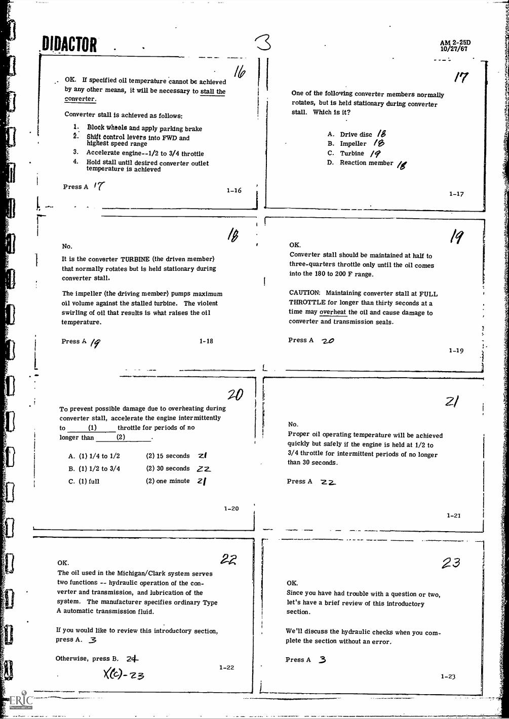
OK. If specified oil temperature cannot be achievedby any other means, it will be necessary to stall theconverter.
Converter stall Is achieved as follows:
1. Block wheels and apply parking brake2. Shift control levers into FWD and
highest speed range3. Accelerate engine-1/2 to 3/4 throttle4. Hold stall until desired converter outlet
temperature is achieved
Press A t r
No.
It is the converter TURBINE (the driven member)that normally rotates but is held stationary duringconverter stall.
The impeller (the driving member) pumps maximumoil volume against the stalled turbine. The violentswirling of oil that results is what raises the oiltemperature.
Press A 1-18
AM 2-25D10/27/67
One of the following converter members normallyrotates, but is held stationary during converterstall. Which is it?
A.
B.
C.D.
Drive disc ISImpeller /OPTurbine /9Reaction member ig
/7
1-17
To prevent possible damage due to overheating duringconverter stall, accelerate the engine intermittently
throttle for periods of no(2)
to (1)
longer than
A. (1) 1/4 to 1/2
B. (1) 1/2 to 3/4
C. (1) full
(2) 15 seconds
(2) 30 seconds
(2) one minute
zi
zi
1-20
OK.
The oil used in the Michigan/Clark system servestwo functions -- hydraulic operation of the con-verter and transmission, and lubrication of thesystem. The manufacturer specifies ordinary TypeA automatic transmission fluid.
If you would like to review this introductory section,press A. 3
Otherwise, press B. 24-1-22
1
tf
OK.
Converter stall should be maintained at half tothree-quarters throttle only until the oil comesinto the 180 to 200 F range.
CAUTION: Maintaining converter stall at FULLTHROTTLE for longer than thirty seconds at atime may overheat the oil and cause damage toconverter and transmission seals.
Press A -2,0
No.
Proper oil operating temperature will be achievedquickly but safely if the engine is held at 1/2 to3/4 throttle for intermittent periods of no longerthan 30 seconds.
Press A Z2_
OK.
Since you have had trouble with a question or two,let's have a brief review of this introductorysection.
We'll discuss the hydraulic checks when you com-plete the section without an error.
Press A 3
/9
1-19
2/
1-21
1
23
1-23

DOCTOR'
HYDRAULIC CHECKS -- INTRODUCTION
Whenever mechanical adjustment alone does notcorrect improper vehicle performance, it is necessaryto make certain basic oil pressure and flow checks.The results of each individual check should be recordedfor comparison with the results of other checks andwith manufacturer's specifications.
...-Press A 7J
.2-24
I
That is correct.The hydraulic checks are useful not only as atroubleshooting measure, but also as a routinepreventive maintenance measure.
Taking these checks periodically makes it possibleto detect problems prior to an actual breakdown in
the field.
Press A 072-26
L
By analyzing the results of oil pressure and flowchecks, it is possible (in most cases) to isolatethe assembly or component that is the source ofa malfunction. Disassembly and visual inspectionmay then be necessary to pinpoint the specificsource of trouble.
Let's discuss the specific hydraulic checks whichmay be necessary.
Press A 27
s
.AM 2-25D10/27/67
Is the information compiled in the various oilpressure and flow checks useful only as a meansof pinpointing the source of a malfunction?
A. Yes" XX
B. No 20
(Only the correct answer will move the film. )
2-25
Periodic preventive maintenance checks allow youto schedule vehicle downtime. This is good main-tenance management.
Usually it is better to take care of minor difficultiesas they occur, rather than to wait for a majorbreakdown. Scheduled repairs of minor problemsusually mean lower overall maintenance costs andless downtime in the long run.
Press A -ze32-27
OIL PRESSURE AT CONVERTER OUT
Install a hydraulic pressure gauge at the pressureconnection on the converter regulating valve. This
point is marked converter out. Readings at this
point give you converter internal pressure.
See Plate I. Converter internal pressure is read at
A. location "G" 30B. location "D" 3 2...
2-28 C. location "C" 31
rYou are incorrect. (See Plate I.)
Location "G" is the check point for converterleakage (converter lube flow), which we will
cover later in this film.
To check converter internal pressure, install apressure gauge at location "D" (converter out).
Incorrect.Location "C" is the check point for converter inpressure. We will talk about that shortly.
To check converter internal pressure, install apressure gauge at location "D" (converter out).
Press A 5 2..,
zq
2-29
'3/
2-31
t"

4
DIDACTOR
r
OK. Converter internal pressure (converter outpressure) is read at location "D". This. pressureshould be checked both at 2000 rpm and at high freeidle (engine at full throttle).
Maxi Mum converter internal pressures for variousconverter models are:
Model C-270Model C-8000Model C-16000
Press A 33
40 to 45 psi60 to 70 psi70 to 80 psi
32
2-32
Your answer is incorrect.
In another film we said that the normal pressure at4 location "C" is 80 psi in neutral at 2000 rpm.
The MINIMUM converter in pressure specified bythe manufacturer is 20 psi.
Press A 3$ "
3'4
2-34
3 6No.
The malfunction most likely to appear when the checkvalve spring is broken (or when the check valve isstuck open) is delayed shifting.
Low oil flow through the cooler and low converter inpressure will result when the converter bypass valveball seat is worn.
Press A o2-36
gOK.Lc.-,v converter in pressure also may be caused by adefective charging pump.
To test the charging pump, connect a flow meterbetween the pump and the filter. Disconnect the linebetween the pump and filter at the filter end.
The line disconnected at the filter should be connectedto the port of the flow meter.
A. pressure 441:9
13. reservoir 3,2-38
OIL PRESSURE AT CONVERTER IN
AM 2-25D10/27/67
33To check converter in pressure, install a hydraulicpressure gauge at location "C" (see Plate I). Checkand record the pressures at 2000 rpm, both at stalland with the transmission-in neutral.
Converter in pressure should not fall below psi.
A. 20 36.B. 60 3y-C. 80 M.
2-33
OK. Minimum pressure at location "C" (Plate I) is20 psi.
If there is low oil flow through the cooler and if con-verter in pressure also is low, the trouble is mostlikely
A.
B.
C.
a broken spring in the check valveplugged lube oil ports in the transmission .37a worn ball seat in the converter bypassvalve
2-35
No.
Plugged lube oil ports in the transmission docause low oil flow through the cooler. but thisusually is associated with high converter outpressure.
Low cooler oil flow and low converter in pressurewill result when the converter bypass valve ballseat is worn.
Press A 3g
2-37
No.
You should detach the line between the pump andfilter at the filter end, and connect this line to thePRESSURE port of the flow meter.
Press A 4'
2-39

VRACTOR'
L
OK. The line leading from the pump should beattached to the pressure port of the flow meter.
Then attach a hose between the reservoir port of themeter and the filter connecting point.
Charging pump flow checks are made at
A. high free idleB. 2000 rpm feyC. low idle 9/
2-40
OK. Take the pump output check at 2000 rpm. 1.1?
Do not use the tester load valve at any time during thetest. If the needle points to the right half of the flowgauge, switch to the next higher scale.
The pump is defective if the flow gauge reads morethan percent below the rated output for thepump.
A. 30 9.3B. 10 6',C. 20 441
2-42
OK. The pump is defective if its flow rate fallsmore than 20 percent below its rated capacity.
A defective converter charging pump should be
A. repaired if possible 15.B. replaced 1/6
2-44
1,
-
OK. Do not attempt to repair a defective chargingpump. Replace it.
If you would like to review this section, starting withour discussion of preventive maintenance, press A. 211-
Press B if you would like to review only the hydraulicchecks at converter in, converter out and at thecharging pump.
Press E if you prefer to go on.4749
A/6) - 4/7.3-46
AM 2-25D10/27/67
No.The rated output for a new converter charging pumpis the gpm output of that pump at 2000 rpm. A 31gallon pump, for example, will deliver 31 gpm at2000 rpm when new. .
Charging pump flow checks also are made at 2000rpm.
Press A 92..
2-41
r
No.
A 20 percent tolerance below rated pump output ispermissible. If the flow rate falls below thatfigure, the pump is defective.
A pump rated at 40 gallons, for example, is defectiveif it shows less than 32 gpm on the flow check.
Press A 115Z.
2-43
No. The manufacturer recommends that no attemptbe made to repair a defective charging pump.
Defective pumps should be replaced.
Press A rb
2-45
OK. Replace, the defective converter charging pump.Do not attempt to repair it.
You have made an error or two on the questions inthis section, so let's have a quick review.
If you would like your review to begin with our briefdiscussion of preventive maintenance, press A. 24
Press B ilflou want to review only the hydraulicchecks at converter out, converter in and at thecharging pump.
2-47

DRACHM
TRANSMISSION CLUTCH PRESSURE AND LEAKAGEitn 1
If the pump output test does not discloie the source oftrouble, proceed to the.clutch pressure checks.
See Plate I. Clutch pressures are checked at
A. location "F" 17/B. location "B" 9/C. location "H"
3-48
Incorrect. (See Plate I. )
Location "H" is the check point for oil volume be-tween the transmission and converter. This checkhelps you to determine clutch leakage. We'll talkmore about clutch leakage shortly.
CLUTCH PRESSURE checks are taken at location "B".
Press A Sy
3-50
Next, shift the direction control lever into REV andcheck the pressure in at least the 1st speed range.Record this pressure.
If all pressures recorded thus far are EQUAL or arewithin five psi of one another, it will not be necessaryto check any more combinations of clutches forpressure.
Press A 6-33-52
1
You are incorrect. (See Plate IL )
Note that the pressures obtained in forward and theodd-numbered speed ranges are low -- 190 psi,compared to 200 psi for all other combinations.
We know that in the odd-numbered forward speedranges the LO FORWARD clutch is engaged. Sincethe pressure is low in each range in which the LOFORWARD clutch is engaged, that clutch is defective.Press A 6-0,
3-54
lir .4
A
AM 2-25D10/27/67
You are incorrect. (See Plate I. )
Pressure at location "F" is transmission lubepressure. We'll.talk more about this later in thefilm.
CLUTCH PRESSURE checks are taken at location "B".
Press A
3-49
OK. Check clutch pressures at location "B". (Plate I)
Remember that all pressures must be taken with hotoil and with two clutches engaged. Engine speedmust remain constant (low idle) throughout theclutch pressure and leakage checks.
Shift the direction control lever into FWD and checkpressure in 1st through 8th speeds. Record thepressure for each range.
Press A
L _
3-51
L.
A faulty clutch can be discovered by the process ofelimination. When the pressure in any clutch variesmore than five.pst from the others, it must be re-paired or replaced.
See Plate II. This is a list of pressures obtained in aclutch pressure check. From this information. youwould suspect that the
A.
B.
C.
LO forward clutch is defective .0HI forward clutch is defective 5e,<-odd-numbered speed clutches both are 5-9,defective
3-53
You are incorrect. (See Plate II. )
Note that the pressures obtained in ALL the odd-numbered forward SPEED RANGES are low -- 190psi, compared to 200 psi for all other combinations.
We know that in the odd-numbered forward speedranges, the LO FORWARD clutch is engaged. Sincethe pressure is low in each range in which the LOforward clutch is engaged, that clutch is defective.
Press A 54.3-55

DIDACTORt
OK. (See Plate IL) The pressures are low in theodd-numbered forward speed ranges only. Thismeans that the LO FORWARD clutch is defective.
L5
If the pressures had been low in the even-numberedforward gears, and equal in all other combinations,it would mean that the HI FORWARD clutch isdefective. The HI FORWARD clutch is engaged inall the even-numbered forward gears.
Press A 593-56
No.
If all other combinations are equal within five psi,and if the pressures vary more than five psi inforward and the 1st and 2nd speed ranges, it meansthat only the FIRST speed clutch is defective.
i
The first speed clutch is engaged with the LO forwardclutch in 1st speed range and with the HI forwardclutch in 2nd speed range.
Press A 03-58
6,OK. The first speed clutch is defective.
If all pressures had been equal within five psi exceptthose obtained in forward and 3rd. and forward and4th, then the SECOND speed clutch would have beendefective. The second speed clutch is engaged inthe 3rd and 4th speed ranges.
Press A 6
3-60
You have had some trouble with at least one questionso far.
Before we discuss the clutch leakage checks, let'shave a quick review of the clutch piessure checks.
Press A 9.13
3-61.1
I
I
I
I
AM 2-25D10/27/67
Let's say that you check all the forward clutch com-binations and find that the pressures are equal withinfive psi, except for the 1st and forward, and the 2nd andforward gear combinations.
This means that the
A. first and second speed clutches are both icedefective
B. second speed clutch is defective .5-9C. first speed clutch is defective 00
3-57
t_
0No.
The second speed clutch is NOT engaged in either the1st or 2nd speed range. In 1st and 2nd speeds, onlythe FIRST speed clutch is engaged (with LO forwardin 1st; with HI forward in 2nd).
Since the pressures are equal within five psi in allother combinations, the FIRST speed clutch isdefective.
Press A 60
c
it
1
t
,
1
f
3-59 1
i
i
r1
i
4
If the source of trouble is not found by checkingclutch pressures, proceed with the clutch leakagechecks. See Plate I.
The leakage for a clutch is determined by SUB-TRACTING the oil flow at location "H" from thepump volume flow, taken at location "A". Again,each speed range should be checked in forward. Atleast the 1st speed range in reverse should bechecked.
Press A 67--- r(e)- 6/, t
0/
3-61
See Plate I.We will assume that you have already checked pumpoutput at 2000 rpm (as discussed in the previoussection of this film), and have found the pump to bein good condition.
For the clutch leakage checks it will be necessaryto check pump output at LOW IDLE. Install a flowmeter at location "A" and record the reading.
Press A 6a3-62

a
DIRACTOR'
Now, install the flow meter at location "H" (Plate I).Check the oil volume flow at low idle in all speedranges in forward, and in at least the first speedrange in reverse. Record each reading carefully.
In order to determine the clutch leakage, subtractthe reading obtained in each speed range from theoriginal pump output reading taken at location "A".
Press A /
3-63
Incorrect. (See Plate Di )
The pump volume in this case is eight gpm. In boththe 1st and 2nd speed ranges, the flow from thetransmission is six gpm. We know that the firstspeed clutch is engaged in both the 1st and 2nd speedranges.
In either case, the leakage past the first speed clutchis eight minus six or two gpm.
Press A 3-65
No.Clutch leakage is one gpm for both the secord andthird speed clutches.
Oil flow in 3rd and 4th is seven gpm. Eight gpmminus seven gpm equals one gpm leakage past thesecond speed clutch. The same is true for thethird speed clutch (engaged in 5th and 6th gears).
Press A 683-67
The leakage around any one of the clutches can bedetermined by a systematic comparison of the oilflow readings in the different speed and directionranges.
The manufacturer also lists specifications formaximum TOTAL leakage around the clutches forthe various vehicle series. In the 16000 Series,for example, the combined total leakage around allthe clutches must not exceed seven gpm. Press A
r4
6r
3-69
AM 2-25D10/27/67
See Plate III. This is a list of readings obtained ina clutch leakage check. The pump output volumewas found to be eight gpm.
The oil flow from the transmission at location "H"(Plate I) is six gpth in the forward and 1st and theforward and 2nd speed combinations.
This means that leakage past the first speed clutchis
A. six 445.B. twoC. eight 4,5*
3-64
OK.
The leakage past the first speed clutch is two gpm(eight gpm minus six gpm). See Plate III.
The manufacturer recommends that if leakage in aclutch varies more than one gpm from the others, itshould be repaired or replaced.
From the readings listed in Plate ill, it appears thatthe speed clutch is defective.
A. seconuB. third 67C. fourth 4,,o 3-66
r
68OK. See Plate III. In the 7th and 8th speed ranges.oil flow from the transmission is four gpm. TheFOURTH speed clutch is engaged in 7th and 8thspeeds.
In either case the leakage past the fourth speed clutchis four gpm (eight gpm minus four gpm). Since thisfigure varies from the leakage around the otherclutches by more than one gpm. the fourth speed.clutch is defective and must be serviced. (It alsoappears that the first speed clutch needs someattention. ) Press A6,;
3-68
A certain amount of leakage around each clutch isnormal. Assuming that we are speaking of a vehicleof the 16000 Series, the leakage around any singleclutch must not exceed gpm.
A. seven 97B. two
C. one
3-70

DOI ACTOR
1
ON
Your answer is incorrect.
Remember that there are SEVEN clutches in theMichigan/Clark transmission -- four speed clutchesand three direction clutches. Manufacturer'sspecifications state that maximum total clutch leak-age for the 16000 Series is seven gpm.
Since there are seven clutches, and since we canexpect SOME leakage around each clutch, themaximum allowable leakage around an individualclutch is one gpm.
Press A 7 2,
3-71
72OK. In a 16000 Series vehicle) the leakage past anyclutch should not exceed one gpm.
Since you have made an error or two on the questions,let's have a quick review. Press A if you want toreview both the checks for clutch pressure and clutchleakage. 0Press B if you want to review only the clutch leakagechecks. 6/
3-73
If the pressure at location "F" (Plate I) is lowerthan six psi:
A. the oil volume probably is low 77
B. the tubing that feeds the bearingsand clutches probably is clogged 74
AM 2-25D10/27/67
Good. The maximum leakage for any single clutchin a 16000 Series vehicle is about one gpm.
74
You have completed this section on transmission clutchpressure and leakage without an error. If you wouldlike to review this section, press A. fie
Press B you want to review only the section ondutch leakage.
Press E if you prefer to go on.
4-72
LUBE FLOW AND CONVERTER LEAKAGE
See Plate I. At location "F" you can check thetransmission lube pressure going to the bearings andclutches. This pressure check should be taken at2000 rpm and at high free idle. The normal pressureat 2000 rpm is 6 to 12 psi. The maximumrecommended pressure at high free idle is 25 psi.
Press A 75
-74
J
4 -75
rigOK. (See Plate I.) If the pressure at 2000 rpm islower than six psi (at location "F"), there is low oilvolume. It will be necessary to check pump output.
If lube pressure is higher than psi at highfree idle. the lubrication tubing probably is clogged.
A. 6 70,B. 12 7gC. 25 /91
7No.
Clogged lubrication tubing will cause the lubepressure to be higher than normal.
When lube pressure is LOWER than normal (lessthan 6 to 12 psi). you should suspect low oil volume.
Press A 77
4-7C
Incorrect.Normal lube pressure is 6 to 12 psi at 2000 rpm.
At high free idle (engine at full throttle), the lubepressure normally will not exceed 25 psi. Anypressure higher than this indicates cloggedlubrication tubing.
Press A 794-78

-1)11)ACTOR.
As a general rule, pressures below normal indicateLOW OIL VOLUME. Pressures above normalindicate that somcthing is CLOGGED (normal flowis restricted).
f
OK. Maximum normal lube pressure at high freeidle is 25 psi.
Press A 80
7f
4-79
Measure the voluine of oil you have collected in15 seconds, and multiply this volume by four toget the converter leakage in gallons per minute.Compare this against manufacturer's specifications.
See Plate I. Converter leakage is measured from
A.
B.
C.
location "A" elocation "D" &z-location "G"
4-81
OK.
According to manufacturer's specifications. con-verter leakage in the C8000 Series must not exceedfive gpm at 2000 rpm.
This means that leakage measured from location "G"(Plate I) may not exceed gallons in 15seconds.
A. 1 1/4B. 1 1 2
C. 24-83
OK.
If you would like a brief review of the lube flow andconverter leakage checks, press A. 7$
Otherwise, press B. 17
4-85
J
AM 2-25D10/27/67
The manufacturer also issues specifications formaximum converter leakage for the various vehicleseries.
To check converter leakage. disconnect the con-verter DRAINBACK LINE (Plate I, location "G").Connect an auxiliary hose to the drainback line.With the engine at 2000 rpm, collect the leakage fromthis hose for 15 seconds.Press A toy
4-80
No. (See Plate I.)
Converter leakage is checked by disconnecting theconverter drainback line. Converter leakage ismeasured from location "G".
Press A 93
tr
ti
You are incorrect.
Maximum allowable converter leakage for theC8000 Series is five gpm at 2000 rpm.
89
If the maximum allowable leakage is five gallonsper minute. then the maximum allowable leakagefor 15 seconds is 1 1/4 gallons per minute. Fivedivided by four equals 1 1/4 gallons per 15 seconds.
Press A 6?6-P.4
OK. Maximum allowable oil leakage from a C8000Series converter is 1 1/4 gallons in 15 seconds(at 2000 rpm).
Let's have a quick review of the lube flow and con-verter leakage checks now, since you made anerror on at least one question.
Press A 79'1 -86

DIDACTOR I a_
17 1
This section of the film is intended as a quick review,to help you remember the locations for the varioushydraulic checks required on Michigan/Clark con-verter and transmission assemblies.
Refer to Plate I throughout this section. In eachcase, only the correct answer will move the film.
Press A go
OK. Converter out pressure (converter internalpressure) is checked at location "D".
Converter in pressure is measured at
4-87
See Plate I.Converter out pressure is measured at
A. location "G"
B. location "D"
C. location "C"
AM 2-25D10 /27/67
Remember that only the correct answer will move thefilm. 4-88
OK. Converter in pressure is checked at location"Cl
Pump output is measured at
A. location "A" yor A. location "A" 9/yB. location "B" B. location "13"
C. location "C" C. location "G" XX
....4-89
OK. Pump output is checked at location A.
Clutch pressure is measured at
A.
B.
C.
9/
location "F" YA/location "B" 92..location "H" ,la
OK. Clutch leakage is checked at location
Converter leakage is measured at
A.
B.
C.
location "A" lir
location "D" )0(
location ty" 94/
'+ -91
1
.4 -90
- 93
r.2OK. Clutch pressure is checked at location B.
Transmission clutch leakage is measured at
A.
13.
C.
location "F" rylocation "G" )(location "H" 4 7/
ffOK.
Converter leakage (lube flow from the transmission)is checked at location -G".
Transmission lube pressure is measured at
A.
B.
C.
location "F"location "B"location "E"
XY)(K
-9'4


tl
11
INSTRUCTOR'S GUIDE
Title of Unit: MICHIGAN/CLARK TRANSMISSION --TROUBLESHOOTING
OBJECTIVES for this Unit:
AM 2-2510/19/67
1. To give the student a series of systematic inspectionand troubleshooting checks.
2. To present certain readings (rpm, gpm, psi) whichare critical when inspecting and troubleshooting thevarious Michigan/Clark transmissions.
LEARNING AIDS suggested:
Models:Arrangements can be made to have a working modelof a Michigan/Clark transmission at your center.A teardown and reassembly of this equipment on aclass participation basis would be excellent duringthese discussions.
QUESTIONS DESIGNED FOR CLASS PARTICIPATION:
1. What are the preliminary checks that should be madewhen troubleshooting a unit?
2. How can the oil be brought up to the desired tempera-ture for purposes of checking?
3. What oil pressure reading should be obtained at con-verter out? At converter in?
4. How can transmission clutch leakage be checked?
5. How can converter lube flow be checked?
6. What can cause a low volume oil condition?
7. In making checks across the cooler, what makes upthe reading that is obtained at (E) in Figure 1 ?


![Vol XXV], No.]](https://static.fdocuments.us/doc/165x107/625486dcdc949f59821fe028/vol-xxv-no.jpg)


