RELEVANCE OF SHELL AND DOME STRUCTURES IN … PDF/Archive-2015/May-2015/9.pdf · Shell structures...
7
[Gana., 2(5): May, 2015] ISSN: 2349-4506 Global Journal of Engineering Science and Research Management http: // www.gjesrm.com © Global Journal of Engineering Science and Research Management 48 RELEVANCE OF SHELL AND DOME STRUCTURES IN MODERN APPLICATIONS OF CIVIL ENGINEERING CONSTRUCTION Dr. Engr. Gana .A.J *1 1* COREN Regd, MNSE, MNICE,Istructe Lond (U.K,) ICE Lond (U.K) Civil Engineering Department College of science and Engineering Landmark University Omu-Aran, Kwara state.. *Correspondence Author: Dr. Engr. Gana .A.J Keywords: Relevance, shell, Dome, modern Application. Abstract Shell and Dome structures are structural elements of members with curved surface that are capable of transmitting loads in more than two directions to support loads. They are highly efficient structural when they are well shaped, proportioned, and supported by transmitting the applied wads without any form of twisting or bending. The modern applications of shell and Dome structures in civil Engineering construction has increased the benefits of enclosed space and span distances by these two structures. This paper examined the relevance of shell and Dome structures in this present modern Application of civil Engineering construction. Introduction Shell and dome structures often offered many of the attributes that the architects and engineers are looking for in an ideal structure. A shell and dome structure provides only a few centimeters thick, which can cover very. Large spans, singly and in combination are practically numberless. Shell and dome are in thin in thickness because they are curved in such a fashion as to keep bending stresses to a minimum. The extent of their economy, value of aesthetic, effects, suitability to functional requirements, and how well their structural behavior is understood. Therefore shell and dome structure offer new solutions for the designed of enclosed space and span distances, with the economy of materials in view and freedom of forms. Material and Method The adopted method for this paper was through visits to places where there are already existing buildings with the construction of Dome like mosques of similar purpose and uses within kwara state; public Government offices with walk ways in public institutions and places where the construction and application of shell structures and obtained. Historical Application of shell and Dome structures World Wide Shell and Dome structures are among the oldest means of enclosing large spaces, especially from the Hajia Sophia in Instanbul, to the classical era of cathedral Architecture. Shell and Dome structures have been used over many centuries in civil Engineering construction Worldwide. The records shown below are notable applications of these structures in different parts of the world. Table 1. Dimension of several shell and structure (1) The structures with bold names are described in these notes. Structure Location, year, architect Geometry Dimensions Radius a Thickness t Ratio a/t Chicken egg 150 10 6 BC Surface of revolution 60 m m length 20 mm minimum 0.2-0.4 mm 100 Treasury of Atreus Moknves Greece 1100 BC Surface of revolution 14.5 m diameter 16 m =0.8m 20 pantheon Rome 126 A D Hemisphere 43.4 m diameter 2.17 m 1.2 m at the top 18 Viking ship oseberg Tonsberg Norway 800 A D Ellipsoid part 21.58 m long 5.110 m wide Basilica difirenze Italy 1420 Brunelleschi Octagonal dome 44 m diameter 22 m St. Paul’s cathedral London 1679 wren Cone and hemisphere 35 m diameter 15.25m
Transcript of RELEVANCE OF SHELL AND DOME STRUCTURES IN … PDF/Archive-2015/May-2015/9.pdf · Shell structures...

[Gana., 2(5): May, 2015] ISSN: 2349-4506
Global Journal of Engineering Science and Research Management
http: // www.gjesrm.com © Global Journal of Engineering Science and Research Management
48
RELEVANCE OF SHELL AND DOME STRUCTURES IN MODERN APPLICATIONS OF CIVIL
ENGINEERING CONSTRUCTION Dr. Engr. Gana .A.J*1
1* COREN Regd, MNSE, MNICE,Istructe Lond (U.K,) ICE Lond (U.K) Civil Engineering Department College of science and
Engineering Landmark University Omu-Aran, Kwara state..
*Correspondence Author: Dr. Engr. Gana .A.J
Keywords: Relevance, shell, Dome, modern Application.
Abstract Shell and Dome structures are structural elements of members with curved surface that are capable of transmitting loads in more
than two directions to support loads. They are highly efficient structural when they are well shaped, proportioned, and supported by
transmitting the applied wads without any form of twisting or bending. The modern applications of shell and Dome structures in
civil Engineering construction has increased the benefits of enclosed space and span distances by these two structures. This paper
examined the relevance of shell and Dome structures in this present modern Application of civil Engineering construction.
Introduction Shell and dome structures often offered many of the attributes that the architects and engineers are looking for in an ideal structure.
A shell and dome structure provides only a few centimeters thick, which can cover very. Large spans, singly and in combination are
practically numberless. Shell and dome are in thin in thickness because they are curved in such a fashion as to keep bending stresses
to a minimum. The extent of their economy, value of aesthetic, effects, suitability to functional requirements, and how well their
structural behavior is understood. Therefore shell and dome structure offer new solutions for the designed of enclosed space and
span distances, with the economy of materials in view and freedom of forms.
Material and Method The adopted method for this paper was through visits to places where there are already existing buildings with the construction of
Dome like mosques of similar purpose and uses within kwara state; public Government offices with walk ways in public institutions
and places where the construction and application of shell structures and obtained.
Historical Application of shell and Dome structures World Wide
Shell and Dome structures are among the oldest means of enclosing large spaces, especially from the Hajia Sophia in Instanbul, to
the classical era of cathedral Architecture. Shell and Dome structures have been used over many centuries in civil Engineering
construction Worldwide. The records shown below are notable applications of these structures in different parts of the world.
Table 1. Dimension of several shell and structure (1)
The structures with bold names are described in these notes.
Structure Location, year,
architect
Geometry Dimensions Radius
a
Thickness
t
Ratio a/t
Chicken egg 150 106 BC Surface of
revolution
60 m
m length
20 mm
minimum
0.2-0.4
mm
100
Treasury of Atreus
Moknves Greece 1100
BC
Surface of revolution
14.5 m diameter
16 m =0.8m 20
pantheon Rome 126
A D
Hemisphere 43.4 m
diameter
2.17 m 1.2 m
at the top
18
Viking ship
oseberg
Tonsberg
Norway 800 A
D
Ellipsoid part 21.58 m long
5.110 m wide
Basilica
difirenze
Italy 1420
Brunelleschi
Octagonal
dome
44 m
diameter
22 m
St. Paul’s
cathedral
London 1679
wren
Cone and
hemisphere
35 m diameter 15.25m

[Gana., 2(5): May, 2015] ISSN: 2349-4506
Global Journal of Engineering Science and Research Management
http: // www.gjesrm.com © Global Journal of Engineering Science and Research Management
49
Jana planeta Germany 1923 dischinger,
finterwakder
Hemisphere 25 m Diameter
12.5m 0.06m 200
Jana factory Germany 1923 Spherical cap 40 m
Diameter
28.28m 0.06m 470
Algeciras
market hall
Spain 1934
Torroja
Spherical cap
on 8 supports
47.6 m
Diameter
44.1m 0.09 490
Beer can 1953 Cylinder 66 mm
diameter
33 mm 0.08mm 410
Hibbing water
filer plant
Minnesota
1939 Tadesko
Elipsoid of
revolution
45.7 m
Diameter
47.24-
5.33m
0.09-0.15
m
35-525
Bryn mawr
factory
Pennysylvania
1947
Elpar on a
rect. Plan
48.0 m
between
supports
34.0m 0.065m 300-400
Auditorium
MIT
Cambridge
1955 Saarinen
Segment Of A
Sphere On 3
Point
48.0 m
between
supports
34.0m 0.065m 520
Kanehoe
shopping center
Hawali 1957 Intersection of
2 tori on 4 supports
39.9 x 39.0 m
between supports
30.9-
78.0m
0.076-
0178m
500-100
palazzetto
Rome 1957 Spherical cap
58.5m 30.9m 0.12m shell
Delllo Nervi With ribs Diameter 0.33m ribs
CNIT Paris
1957 Esquilan
Intersection of
3 cylinders on 3 supports
219 m between
supports
89.9-
420.0m
1.91-2.74
m total 0.06-0.12
outer layer
47.153
Ferrybridge
cooling
tower
Ferrybridge Uk
1960
Hyperboloid Height 155 m 44m 0.13 m
repaired
0….m
350
Apollo
rocket
Houston USA
1961-1972
Cylinder +
stiffeners
Tucker high
school
Henrico USA
1965
4 hypars 47 x 49 m 127 m 0.09 m 1400
Savill
building
Windsor
UK 2005
Freeform Length 98 m
width 24 m
143 m 0.30 m 41
Sillogue
Water Tower
Dublin
2007 collins
Surface of
revolution
Height 39
m top diameter 38 m
24.8 m 0.786 m 32
Discussion Shell: - a shell is a thin, rigid, three dimensional structural form taken by the enclosure of a volume bounded by a curved surface.
The surface of a shell can assume any shape. The common forms of shell include rotational surfaces generated by the rotation of a
curve about it axis, e.g. spherical elliptical, conical, and parabolic surfaces, translational surfaces that is generated by sliding one
curve, over another plane curve, e.g. cylindrical and elliptical, paraboloid surfaces, and ruled surfaces generated by sliding the two
ends of a line segment on two individual plane curves, e.g. hyperbolic and parabolic surfaces and also a wide variety of complex
surfaces that is formed by various combinations of rotational, translation, and ruled surfaces. A shell can assume any of these forms.
It is the construction considerations that usually limit the range of form options chosen.
Types of shell
Shell are of different types both in shapes and in construction. The common types are briefly discussed below:-
[Gana., 2(5): May, 2015] ISSN: 2349-4506
Global Journal of Engineering Science and Research Management
http: // www.gjesrm.com © Global Journal of Engineering Science and Research Management
50
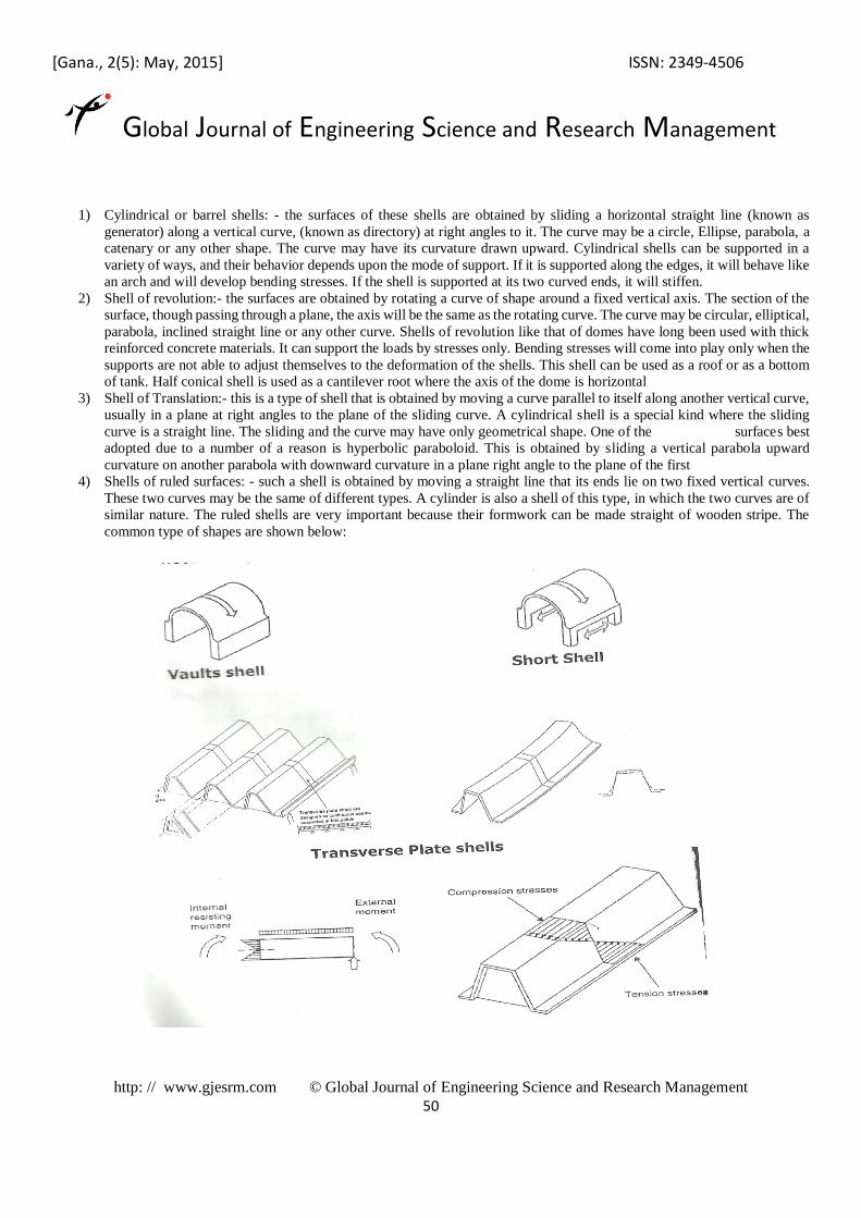
1) Cylindrical or barrel shells: - the surfaces of these shells are obtained by sliding a horizontal straight line (known as
generator) along a vertical curve, (known as directory) at right angles to it. The curve may be a circle, Ellipse, parabola, a
catenary or any other shape. The curve may have its curvature drawn upward. Cylindrical shells can be supported in a
variety of ways, and their behavior depends upon the mode of support. If it is supported along the edges, it will behave like
an arch and will develop bending stresses. If the shell is supported at its two curved ends, it will stiffen.
2) Shell of revolution:- the surfaces are obtained by rotating a curve of shape around a fixed vertical axis. The section of the
surface, though passing through a plane, the axis will be the same as the rotating curve. The curve may be circular, elliptical,
parabola, inclined straight line or any other curve. Shells of revolution like that of domes have long been used with thick
reinforced concrete materials. It can support the loads by stresses only. Bending stresses will come into play only when the
supports are not able to adjust themselves to the deformation of the shells. This shell can be used as a roof or as a bottom
of tank. Half conical shell is used as a cantilever root where the axis of the dome is horizontal
3) Shell of Translation:- this is a type of shell that is obtained by moving a curve parallel to itself along another vertical curve,
usually in a plane at right angles to the plane of the sliding curve. A cylindrical shell is a special kind where the sliding
curve is a straight line. The sliding and the curve may have only geometrical shape. One of the surfaces best
adopted due to a number of a reason is hyperbolic paraboloid. This is obtained by sliding a vertical parabola upward
curvature on another parabola with downward curvature in a plane right angle to the plane of the first
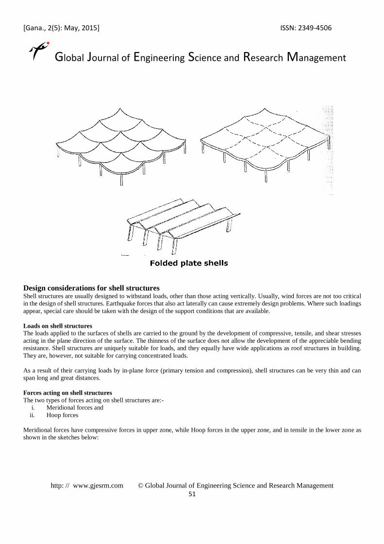
4) Shells of ruled surfaces: - such a shell is obtained by moving a straight line that its ends lie on two fixed vertical curves.
These two curves may be the same of different types. A cylinder is also a shell of this type, in which the two curves are of
similar nature. The ruled shells are very important because their formwork can be made straight of wooden stripe. The
common type of shapes are shown below:
[Gana., 2(5): May, 2015] ISSN: 2349-4506
Global Journal of Engineering Science and Research Management
http: // www.gjesrm.com © Global Journal of Engineering Science and Research Management
51
Design considerations for shell structures Shell structures are usually designed to withstand loads, other than those acting vertically. Usually, wind forces are not too critical
in the design of shell structures. Earthquake forces that also act laterally can cause extremely design problems. Where such loadings
appear, special care should be taken with the design of the support conditions that are available.
Loads on shell structures
The loads applied to the surfaces of shells are carried to the ground by the development of compressive, tensile, and shear stresses
acting in the plane direction of the surface. The thinness of the surface does not allow the development of the appreciable bending
resistance. Shell structures are uniquely suitable for loads, and they equally have wide applications as roof structures in building.
They are, however, not suitable for carrying concentrated loads.
As a result of their carrying loads by in-plane force (primary tension and compression), shell structures can be very thin and can
span long and great distances.
Forces acting on shell structures
The two types of forces acting on shell structures are:-
i. Meridional forces and
ii. Hoop forces
Meridional forces have compressive forces in upper zone, while Hoop forces in the upper zone, and in tensile in the lower zone as
shown in the sketches below:

[Gana., 2(5): May, 2015] ISSN: 2349-4506
Global Journal of Engineering Science and Research Management
http: // www.gjesrm.com © Global Journal of Engineering Science and Research Management
52
Support conditions for shell structures Fixed Edge
Generally, the support conditions for shell structures can be any of the three below. The support conditions should be such that they
do not tend to cause any bending to be developed in the shell structures. Fixed edge condition should not be allowed for reason
stated below:
The roller edges are desirable in that they allow movements to occur more freely, but are very difficult to construct.
Construction Reinforcement for Shell Structures The construction reinforcement for shell structures should be controlled by using reinforcement of different lengths, in order to
check the shell surface. In practical construction considerations, some bending is often allowed to develop at the shell edge for the
sake of easy constructions. The shell should be stiffened by increasing its thickness around the edge and reinforced for bending.
DOME
A dome is a three dimensional space structure, which is used to provide an easy and economic method of roofing to a large area. It
also improves the appearance of the structure. When a dome is to be provided as the roof, a well is usually kept in the building. The
well may be of a shape, such as a square, hexagonal, octagonal, etc. but the top of the dome is converted into a circular shape by a
suitable formwork. The height of spring level of a dome above ground level is always kept at least equal to three storeys to present
a passage appearance. The diameter of a dome may vary from 12 meters to 20 meters or even more for a particular design. The
common types of shapes are shown below:

[Gana., 2(5): May, 2015] ISSN: 2349-4506
Global Journal of Engineering Science and Research Management
http: // www.gjesrm.com © Global Journal of Engineering Science and Research Management
53
Construction of Domes Domes are generally constructed in reinforced concrete. The construction of Domes required the design and applications of form
work. The types of formwork required for Domes construction are:-
i. Solid formwork: - in case of solid formwork, the posts are carried from plinth up to the springing. Level of the Dome. This
present a passage appearance type of formwork is used when there are projections around the Dome solid walls. Suitable
cross-section preferably at each floor level may be provided to increase the rigidity of the formwork.
ii. Suspended formwork:- The skeleton of formwork is suspended from the spring level of the Dome. This type of formwork
is adapted when solid walls are available at the springing level of Dome. The formworks are supported on these solid walls.
Formwork detailed Construction Procedures The following procedures are usually adopted for the construction of Domes.
1. The formwork is brought up to the springing level of the dome. With this construction, the joists are fixed on the standards
and smaller joists are closely arranged over these joists.
2. With the completion of the working platform, the trusses are placed over it to support the formwork. These trusses are
constructed on the ground by drawing full size sections of the dome at the points where they are to be set up. The trusses
are then dismantled, carried on the platform and again fitted and erected on it. The trusses are never allowed to rest directly
on the platform, but on the jacks. When the trusses are finally adjusted to the true level of the jacks; they are then removed,
and the blocks of hardwood are inserted in place of Jacks.
3. One vertical pole is fixed permanently at the centre during the construction of the formwork for the Dome.
4. A rotating swinging formwork is mounted on the central vertical pole. The shape of the rotating arm usually corresponds
to the shape of the Dome, and hence this arrangement is used to check up the formwork for the Dome. The arm is then
rotated and the portion of the formwork which does not correspond to the shape of the Dome is adjusted by the proper
manipulation or adjustment of the jacks.
5. For hoisting or raising purposes, suitable equipment is erected near the Dome.
6. On the top of trusses, the purlines, rafters, and lagging are provided. The rafters are shaped to the shape of the Dome over
the laggings, and the galvanized iron sheets or wooden boards are fixed to finished up the formwork. The final shape is
then checked by the rotating formwork.
[Gana., 2(5): May, 2015] ISSN: 2349-4506
Global Journal of Engineering Science and Research Management
http: // www.gjesrm.com © Global Journal of Engineering Science and Research Management
54
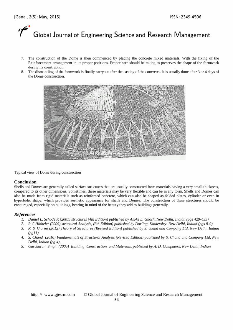
7. The construction of the Dome is then commenced by placing the concrete mixed materials. With the fixing of the
Reinforcement arrangement in its proper positions. Proper care should be taking to preserves the shape of the formwork
during its construction.
8. The dismantling of the formwork is finally carryout after the casting of the concretes. It is usually done after 3 or 4 days of
the Dome construction.
Typical view of Dome during construction
Conclusion Shells and Domes are generally called surface structures that are usually constructed from materials having a very small thickness,
compared to its other dimensions. Sometimes, these materials may be very flexible and can be in any form. Shells and Domes can
also be made from rigid materials such as reinforced concrete, which can also be shaped as folded plates, cylinder or even in
hyperbolic shape, which provides aesthetic appearance for shells and Domes. The construction of these structures should be
encouraged, especially on buildings, bearing in mind of the beauty they add to buildings generally.
References 1. Daniel L. Schode K (2001) structures (4th Edition) published by Asoke L. Ghosh, New Delhi, Indian (pgs 429-435)
2. R.C Hibbeler (2009) structural Analysis, (6th Edition) published by Dorling, Kindersley. New Delhi, Indian (pgs 8-9)
3. R. S. khurmi (2012) Theory of Structures (Revised Edition) published by S. chand and Company Ltd, New Delhi, Indian
(pg11)
4. S. Chand (2010) Fundamentals of Structural Analysis (Revised Edition) published by S. Chand and Company Ltd, New
Delhi, Indian (pg 4)
5. Gurcharan Singh (2005) Building Construction and Materials, published by A. D. Computers, New Delhi, Indian